

Sony KP-43HT20C, KP-53HS30C Service manual

HISTORY INFORMATION FOR THE FOLLOWING MANUAL:
SERVICE MANUAL
MODEL NAME REMOTE COMMANDER DESTINATION CHASSIS NO.
KP-43HT20C
KP-53HS30C
RM-Y908 Chile SCC-P65C-A
RM-Y908 Chile SCC-P65A-A
RA6
CHASSIS
ORIGINAL MANUAL ISSUE DATE: 1/25/02
ALL REVISIONS AND UPDATES TO THE ORIGINAL MANUAL ARE APPENDED TO THE END OF THE PDF FILE.
REVISION DATE REVISION TYPE SUBJECT
1/25/02 No revisions or updates are applicable at this time.
TRINITRON® COLOR TELEVISION
9-965-921-01
Self Diagnosis
Supported model
SERVICE MANUAL
MODEL NAME REMOTE COMMANDER DESTINATION CHASSIS NO.
KP-43HT20C RM-Y908 Chile SCC-P65C-A
KP-53HS30C RM-Y908 Chile SCC-P65A-A
RA-6
CHASSIS
9-965-921-01
RM-Y908 KP-43HT20C/53HS30C
TRINITRON® COLOR TELEVISION

KP-43HT20C/53HS30C
RM-Y908RM-Y908
(CAUTION)
SHORT CIRCUIT THE ANODE OF THE PICTURE TUBE AND THE
ANODE CAP TO THE METAL CHASSIS, CRT SHIELD, OR CARBON
PAINTED ON THE CRT, AFTER REMOVING THE ANODE.
WARNING!!
AN ISOLATION TRANSFORMER SHOULD BE USED DURING
ANY SERVICE TO AVOID POSSIBLE SHOCK HAZARD, BECAUSE
OF LIVE CHASSIS.
THE CHASSIS OF THIS RECElVER IS DIRECTLY CONNECTED
TO THE AC POWER LINE.
SAFETY-RELATED COMPONENT WARNING!!
COMPONENTS IDENTIFIED BY SHADING AND MARK ! ON
THE SCHEMATIC DIAGRAMS, EXPLODED VIEWS AND IN THE
PARTS LIST ARE CRITICAL TO SAFE OPERATION. REPLACE
THESECOMPONENTS WITH SONY PARTS WHOSE PART NUMBERS APPEAR AS SHOWN IN THIS MANUAL OR IN SUPPLEMENTS PUBLISHED BY SONY. CIRCUIT ADJUSTMENTS THAT
ARE CRITICAL TO SAFEOPERATION ARE IDENTIFIED IN THIS
MANUAL. FOLLOW THESE PROCEDURES WHENEVER CRITICAL
COMPONENTS ARE REPLACED OR IMPROPER OPERATION
IS SUSPECTED.
(ATTENTION)
APRES AVOIR DECONNECTE LE CAP DE L’ANODE, COURTCIR-
CUITER L’ANODE DU TUBE CATHODIQUE ET CELUI DE L’ANODE
DU CAP AU CHASSIS METALLIQUE DE L’APPAREIL, OU AU
COUCHE DE CARBONE PEINTE SUR LE TUBE CATHODIQUE OU
AU BLINDAGE DU TUBE CATHODIQUE.
ATTENTION!!
AFIN D’EVITER TOUT RISQUE DELECTROCUTION PROVENANT
D’UN CHÁSSIS SOUS TENSION, UN TRANSFORMATEUR
D’ISOLEMENT DOIT ETRE UTILISÉ LORS DE TOUT DEPANNAGE.
LE CHÁSSIS DE CE RECEPTEUR EST DIRECTEMENT RACCORDÉ Á L’ALIMENTATION SECTEUR.
ATTENTION AUX COMPOSANTS RELATIFS ÁLA
SÉCURITÉ!!
LES COMPOSANTS IDENTIFIÉS PAR UNE TRAME ET PAR UNE
MAPQUE
EXPLOSÉES ET LES LISTES DE PIECES CONT D’UNEIMPORTANCE
CRITIQUE POUR LA SÉCURITÉ DU FONCTIONNEMENT. NE
LES REMPLACER QUE PAR DES COMPOSANTS SONY DONT
LE NUMÉRO DE PIÉCE EST INDIQUÉ DANS LE PRÉSENT
MANUEL OU DANS DES SUPPLÉMENTS PUBLIÉS PAR SONY. LES
RÉGLAGES DE CIRCUIT DONT L’IMPORTANCE EST CRITIQUE
POUR LA SÉCURITÉ DU FONCTIONNEMENT SONT IDENTIFIES
DANS LE PRÉSENT MANUEL. SUIVRE CES PROCÉDURES LORS
DE CHAQUE REMPLACEMENT DE COMPOSANTS CRITIQUES,
OU LORSQU’UN MAUVAIS FONCTIONNEMENT EST SUSPECTÉ.
! SUR LES SCHÉMAS DE PRINCIPE, LES VUES
– 3 –

KP-43HT20C/53HS30C
RM-Y918RM-Y918
TABLE OF CONTENTS
Section Title Page Section Title Page
1. SELF DIAGNOSIS FUNCTION ......................................5
2. DISASSEMBLY
2-1. REAR BOARD REMOVAL.........................................8
2-2. CHASSIS ASSY REMOVAL.......................................8
2-3. SERVICE POSITION...................................................8
2-4. H2 BOARD REMOVAL ..............................................8
2-5. H1 BOARD REMOVAL ..............................................9
2-6. H3 BOARD REMOVAL (KP-43HT20).......................9
2-7. H3 BOARD REMOVAL (KP-53HS30C).....................9
2-8. MIRROR COVER REMOVAL ....................................9
2-9. BEZNET ASSY REMOVAL......................................10
2-10. H4 BOARD AND S BOARD REMOVAL.................10
2-11. AD BOARD AND B BOARD REMOVAL................10
2-12. G BOARD REMOVAL ..............................................10
2-13. A BOARD, D BOARD AND
U BOARD REMOVAL ..............................................11
2-14. PICTURE TUBE REMOVAL....................................11
2-15. HIGH-VOLTAGE CABLE INSTALLATION AND
REMOVAL .................................................................11
3. SET-UP ADJUSTMENTS
3-1. SCREEN VOLTAGE ADJUSTMENT
(COARSE ADJUSTMENT).......................................12
3-2. SCREEN (G2) ADJUSTMENT
(FINE ADJUSTMENT)..............................................12
3-3. DEFLECTION YOKE TILT ADJUSTMENT............12
3-4. FOCUS LENS ADJUSTMENT .................................12
3-5. FOCUS VR ADJUSTMENT......................................13
3-6. 2-POLE MAGNET ADJUSTMENT .........................13
3-7. CENTERING MAGNET ADJUSTMENT.................13
3-8. 4-POLE MAGNET ADJUSTMENT..........................13
3-9. DEFOCUS ADJUSTMENT (BLUE).........................13
3-10. ELECTRICAL ADJUSTMENT BY REMOTE
COMMANDER..........................................................14
3-11. REGISTRATION ADJUSTMENT.............................25
5. SAFETY RELATED ADJUSTMENTS
5-1. HV REGULATION CIRCUIT CHECK AND
ADJUSTMENT..........................................................32
5-2. HV HOLD DOWN CIRCUIT OPERATION
CHECK AND ADJUSTMENT..................................32
5-3. +B MAX VOLTAGE CONFIRMATION ...................32
5-4. +B OVP CONFIRMATION .......................................32
6. DIAGRAMS
6-1. BLOCK DIAGRAM (1).............................................33
BLOCK DIAGRAM (2).............................................34
BLOCK DIAGRAM (3).............................................35
BLOCK DIAGRAM (4).............................................36
BLOCK DIAGRAM (5).............................................37
BLOCK DIAGRAM (6).............................................38
BLOCK DIAGRAM (7).............................................39
BLOCK DIAGRAM (8).............................................40
BLOCK DIAGRAM (9).............................................41
BLOCK DIAGRAM (10)...........................................42
BLOCK DIAGRAM (11)...........................................43
6-2. CIRCUIT BOARDS LOCATION...................................44
6-3. SCHEMATIC DIAGRAMS............................................44
6-4. PRINTED WIRING BOARDS ......................................72
6-5. WAVEFORMS ................................................................84
6-6. IC BLOCK DIAGRAMS ................................................86
6-7. SEMICONDUCTORS ....................................................90
7. EXPLODED VIEWS
7-1. COVER (KP-43HT20) ...............................................91
7-2. COVER (KP-53HS30C).............................................92
7-3. CHASSIS (KP-43HT20)............................................93
7-4. CHASSIS (KP-53HS30C)..........................................94
7-5. PICTURE TUBE........................................................95
8. ELECTRICAL PARTS LIST ........................................96
4. CIRCUIT ADJUSTMENTS
4-1. P & P SUB CONTRAST
ADJUSTMENT (VIDEO) (SCON)............................31
4-2. P & P SUB CONTRAST
ADJUSTMENT (RF) (SCON) ...................................31
4-3. P & P SUB-HUE AND
SUB-COLOR ADJUSTMENT (SHUE, SCOL) .......31
4-4. P & P SUB-HUE AND
SUB-COLOR ADJUSTMENT (SHUE, SCOL) ........31
– 4 –
KP-43HT20C/53HS30C
on the TV ma
power.
SECTION 1
SELF DIAGNOSIS FUNCTION
1. Summary of Self-Diagnosis Function
• This device includes a self-diagnosis function.
• In case of abnormalities, the TIMER/STAND BY indicator automatically blinks. It is possible to predict the abnormality location
by the number of blinks. The Instruction Manual describes blinking of the TIMER/STAND BY indicator.
• If the symptom is not reproduced sometimes in case of a malfunction, there is recording of whether a malfunction was generated
or not. Operate the remote command to confi rm the matter on the screen and to predict the location of the abnormality.
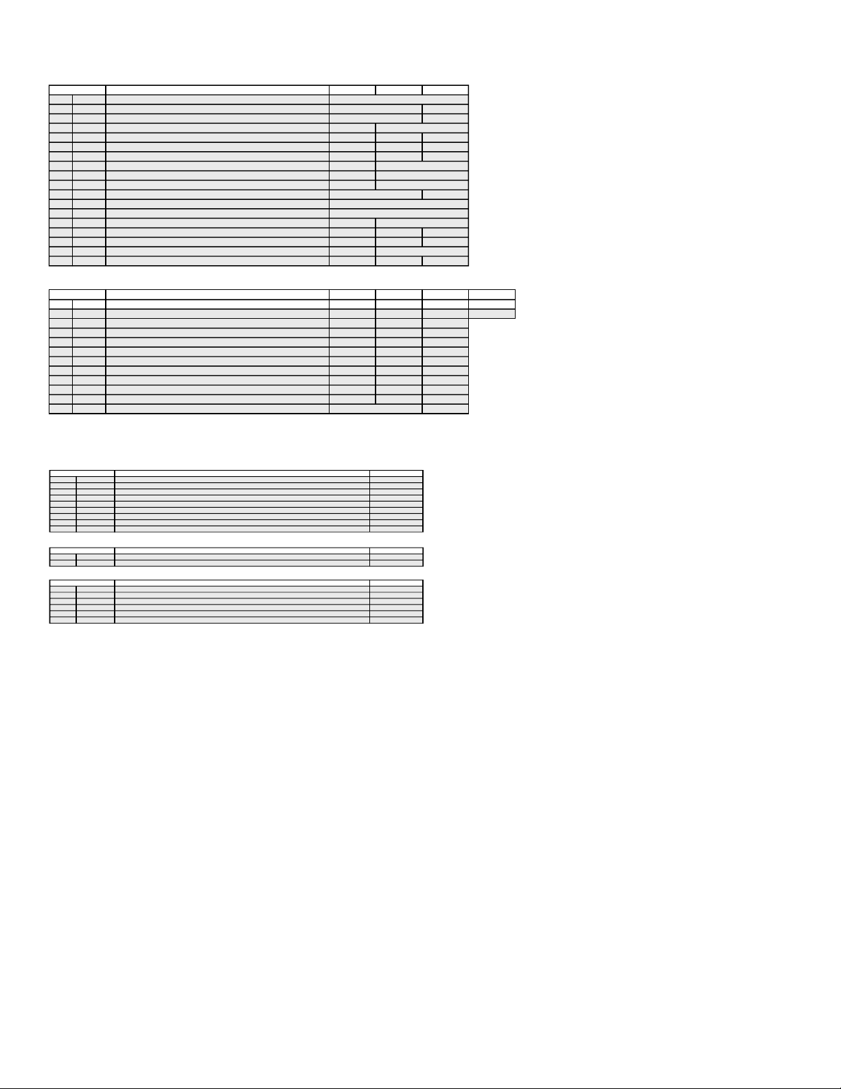
2. Diagnosis Items and Prediction of Malfunction Location
• When a malfunction occurs the TIMER/STAND BY indicator only blinks for one of the following diagnosis items. In case
of two or more malfunctions, the item which fi rst occurred blinks. If the malfunctions occurred simultaneously, the item with
the lower blink count blinks fi rst.
• The screen display displays the results regarding all the diagnosis items listed below. The display “ 0 ” means that no
malfunctions occurred.
RM-Y908RM-Y908
Diagnosis Item
+B overcurrent (OCP)
(See Note 1)
White balance failure
(Not balanced)
LOW B OCP/OVP
(Overcurrent/over voltage)
(See Note 3)
Audio error 9 times
Note1: If a +B overcurrent is detected, stoppage of the vertical deflection is detected simultaneously. The sympton that is diagnosed first by the microcontroller is displayed on screen.
Note 2: Refer to Screen (G2) Adjustment in Section 3-1, 2 of this manual.
Note 3: If TIMER/STANDBY indicator blinks six (6) times, unplug the unit and wait 10 minutes before performing the adjustment.
No. of times
TIMER/STANDBY
indicator blinks
0Power does not turn on
2 times
3 times+B overvoltage (OVP)
4 timesVertical deflection stopped
5 times
6 times
7 timesHorizontal deflection stopped • Q8035, 8038 is shorted. (D board)
8 timesHigh voltage error • T8005 is faulty. (D board)
• Power cord is not plugged in.
• Fuse is burned out (F6001) (G board)
• H. OUT (Q8024) is shorted. (D board)
• +B PWM (Q8035, 8038) is shorted. (D board)
• IC501 is faulty (G board)
• IC5002 is faulty (G board)
• +- 15V is not supplied. (D board)
• IC8003 is faulty. (A board)
• Video out (IC7101, 7201, 7301) is faulty. (CR, CG, CB board)
• CRT drive (IC309) is faulty. (A board)
• G2 is improperly adjusted. (See Note 2)
• +5 line is overloaded. (A, B boards)
• +5 line is shorted. (A, B boards)
• +- 19V line is shorted. (A, B boards)
• IC708 is faulty. (A board)
• PS701 or PS702 is opened. (A board)
Probable Cause Location
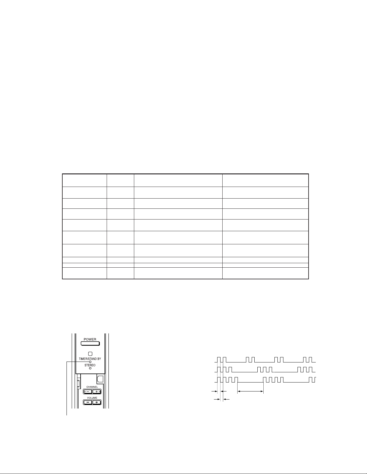
3. Blinking count display of TIMER/STAND BY indicator
* One blink is not used for self-diagnosis.
< FRONT PANEL >
•EXAMPLE
Deteced symptoms
• Power does not come on.
• No power is supplied to the unit.
• AC power supply is faulty.
• Power does not come on.
• Load on power line is shorted.
• Has entered standby mode.
• Has entered standby state after horizontal raster.
• Vertical deflection pulse is stopped.
• Power line is shorted or power supply is stopped.
• No raster is generated.
• CRT cathode current detection reference pulse output is small.
• No picture
• No picture
• No sound
<Diagnosis Items> <Number of Blinks>
• +B overcurrent 2 times
• +B overvoltage 3 times
• Vertical deflection stop 4 times
Lamp ON : 0.3 seconds
Lamp OFF : 0.3 seconds
Lamp OFF :
3.0 seconds
TIMER/STAND BY indicator
Release of TIMER/STAND BY indicator blinking.
• The TIMER/STAND BY indicator blinking display is released by turning OFF the power switch
in unit or removing the plug from the
– 5 –
KP-43HT20C/53HS30C
e
4. Self-diagnosis screen displays
• In cases of malfunctions where it is not possible to determine the symptom such as when the power goes off occasionally or when
the screen disappears occasionally, there is a screen display on whether the malfunction occurred or not in the past (and whether
the detection circuit operated or not) in order to allow confi rmation.
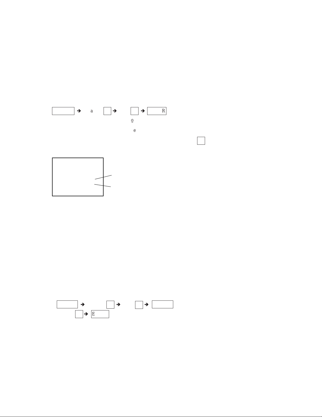
<Screen Display Method>
• Quickly press the remote command button in the following order from the standby state.
RM-Y908RM-Y908
DISPLAY
è
Channel 5 è VOL – è POWER
ñ
Be aware that this differs from the method of
entering the service mode (volume + ).
Self-diagnosis screen display
SELF DIAGNOSIS
2 : +B OCP N/A
3 : +B OVP N/A
4 : V STOP 0
5 : AKB 1
10 : WDT 24
Numeral “0” means that no fault
was detected.
Numeral “1” means a fault was detected
one time or more
5. Self-Diagnosis Screen Display
• The results display is not automatically cleared. In case of repairs and after repairs, check the self-diagnosis screen and be
sure to return the results display to “ 0 ”.
• If the results display is not returned to “ 0 ” it will not be possible to judge a new malfunction after completing repairs.
<Method of Clearing Results Display>
1. Power off (Set to the standby mode)
è
2. DISPLAY
Channel 5 è VOL + è POWER (Service Mod
3. Channel 8 è ENTER (Test reset = Factory preset condition)
<Method of Ending Self Diagnosis Screen>
• When ending the self-diagnosis screen completely, turn the power switch OFF on the remote commander or the main unit.
– 6 –
KP-43HT20C/53HS30C
RM-Y908RM-Y908
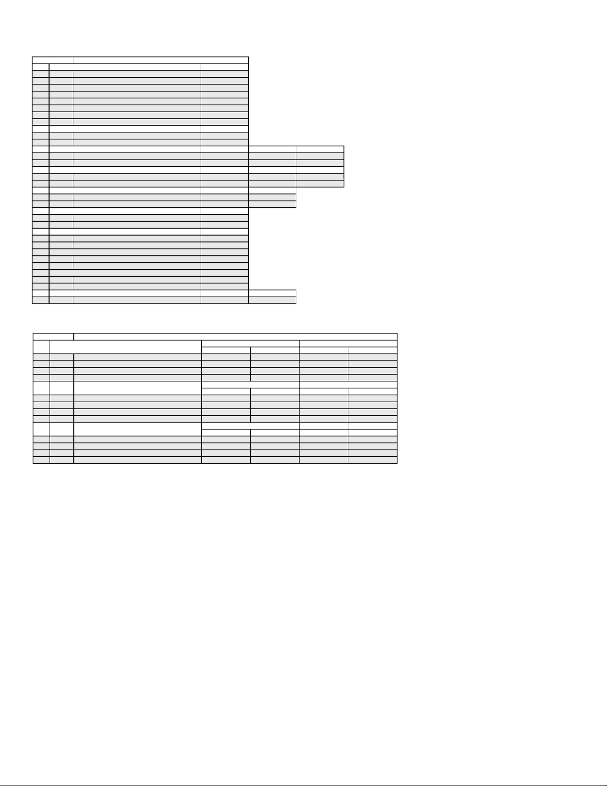
6. Self-diagnosis function operation
OCP Low B and +B line detect DET SHORT, and shut-down POWER ON RELAY.
Reset by turning power on/off.
In case of +B is loaded approx. 1.5A or more, microcomputer detects it via IC5005
OVP In case of +B becomes approx. 150V or more, POWER ON RELAY shuts down and microcomputer detects it via IC5005.
Reset by turning power on/off just the same as OCP.
Low B Occurs when set +5V is out
V Stop In case of V Drive disappeared, Q8001 detecs it and shut-down POWER ON RELAY. Microcomputer detects it and makes LED
blinking.
AKB IK detection. Makes LED blinking in case of microcomputer doesn’t detect IK returns of IC309 (CXA2150AQ) 20 seconds or
more.
H Stop In case of H DRIVE is disappeared, Q378 detects it and shut-down POWER ON RELAY shuts down.
Microcomputer receives H Stop data from Q378 and makes LED blinking.
HV Stop In case of HV becomes 33KV or more. IC8006 detects it and shut-down
POWER ON RELAY. Microcomputer makes LED blinking.
Audio In case of DC component overlaps the output of Audio Amp., POWER ON RELAY shuts down.
Microcomputer detects it and makes LED blinking.
Self-diagnosis block diagram
D9101
TIMER/STANDBY
53
43 244544
49
IC704
MAIN-CPU
5. AKB
31
28
29
30
9. Audio
IC702
EEPROM
IC703
EEPROM
Audio AMP
BUS
IC708
R765
25
26
5. AKB
DC Detect
IC309
CXA2150AQ
Y/C JUNGLE
58
IC8003
V Drive
34
35
6. H STOP
Q378
H PULSE
Detector
4. V STOP
Q8001
V Pulse Detector
C Board
IC8006
HV Detector
6. LOW B
8. HV.STOP
3. OVP
2. OCP
IC5005
OVP Buffer
OCP Buffer
Q714
+5V DETECT
OVP DETECT
OCP DETECT
– 7 –
SECTION 2
DISASSEMBLY
KP-43HT20C/53HS30C
RM-Y908RM-Y908
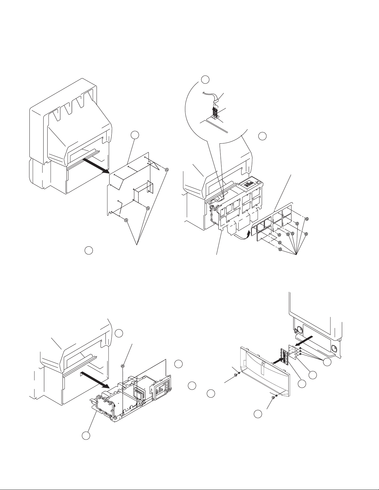
2-1. REAR BOARD REMOVAL
2 Rear board
2-3. SERVICE POSITION
1 Disconnect CN17, 18, 19
on A board.
D board
From V boards CN9001.
(The extension cable is not
A board
CN17, 18, 19
supplied because of the
countermeasure for radiation.)
2 Covers
Cut them off with a plier or the like
from chassis assembly in case of
checking printed circuit boards.
After checking, turn over the covers
and secure them with screws.
1 Eleven screws (Screw(4x20), tapping)
2-2. CHASSIS ASSY REMOVAL
1 Three screws
(Screw(4x20),tapping)
Chassis assembly
2-4. H2 BOARD REMOVAL
2 Screw, dome washer
HEX tap 4x20
1 Cap, speaker grille
2 Screw, dome washer
HEX tap 4x20
Screws
(+BVTP3x12)
3 Six screws
(+BVTP4x12)
4 H2 board
5 Button, multi
1 Cap, speaker grille
2 Chassis assy
– 8 –
KP-43HT20C/53HS30C
RM-Y908RM-Y908
2-5. H1 BOARD REMOVAL
2 Bracket H1
6 Button, power
7 Guide, LED
1 Two screws
(+BVTP4x12)
4 H1 board
3 Screw
(+BVTP4x12)
5 Screw
(+BVTP4x12)
2-7. H3 BOARD REMOVAL (KP-53HS30C)
2 Holder, front terminal
(Except 43HT20)
Holder, side terminal
(43HT20)
3 Two screws
(+BVTP3x12)
1 Screws
(+BVTP4x20)
4 Bracket, H3
7 H3 board
6 Screw
(+BVTP3x12)
5 Door, front terminal
(Except 43HT20)
Door, side terminal
(43HT20)
2-6. H3 BOARD REMOVAL (KP-43HT20)
6 Screw
(+BVTP3x12)
5 Door, side terminal
4 Bracket, H3
3 Two screws
(+BVTP3x12)
7 H3 board
1
2-8. MIRROR COVER REMOVAL
1 Twenty three screws
(Screw(4x20), tapping)
2 Holder, side terminal
2 Mirror cover
– 9 –
KP-43HT20C/53HS30C
RM-Y908RM-Y908
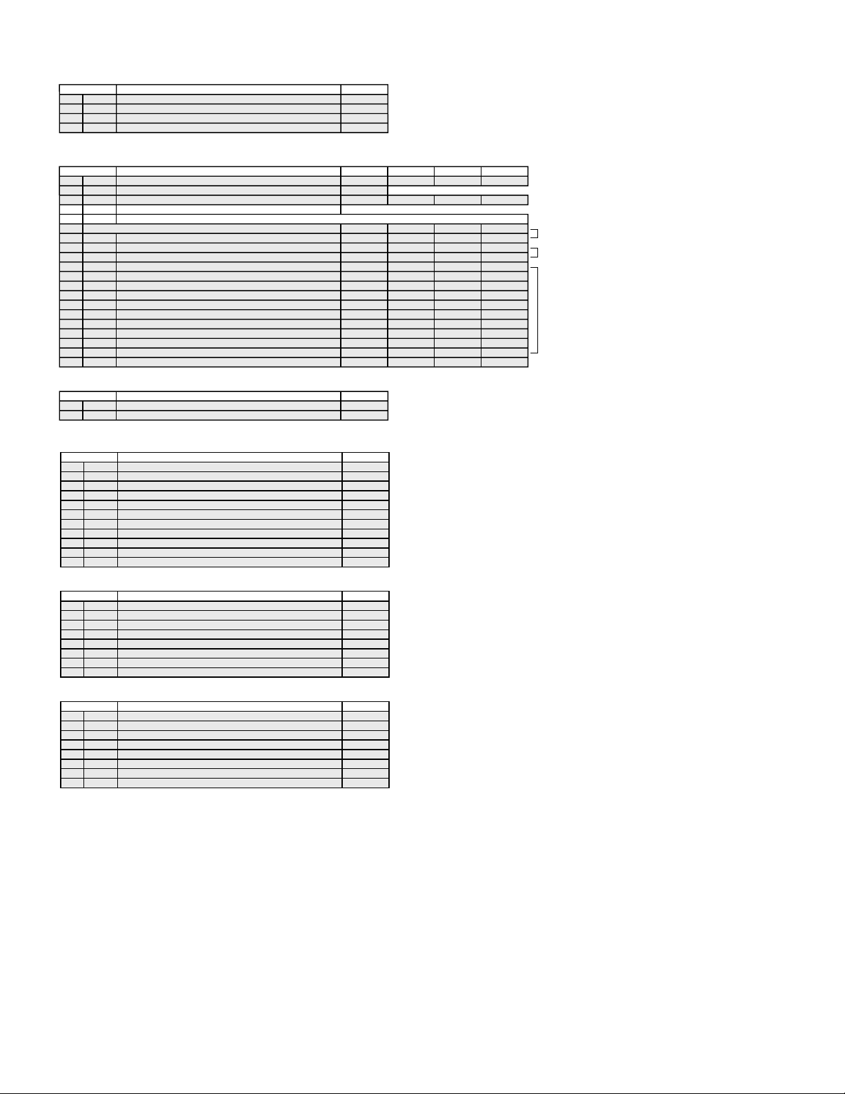
2-9. BEZNET ASSY REMOVAL
2 Screws
(Screws(4x20), tapping)
3 Beznet assy
1 Screws
(Screws(4x20), tapping)
2-11. AD BOARD AND B BOARD REMOVAL
1 B board
1 AD board
Main bracket
2-10. H4 BOARD AND S BOARD REMOVAL
Sensor
Sensor
bracket (B)
bracket (A)
7 S board
6 Clows
4 Two screws
(+BVTP 4x12)
1 Four screws
(+BVTP 4x12)
2 L screen holder
3 H4 board
5 Two screws
(+BVTP 4x12)
2-12. G BOARD REMOVAL
1 Claws
2 Bracket G
1 Claw
1 Claw
3 Four screws
(+BVTP3x12)
4 G board
Main bracket
– 10 –
KP-43HT20C/53HS30C
3
)
RM-Y908RM-Y908
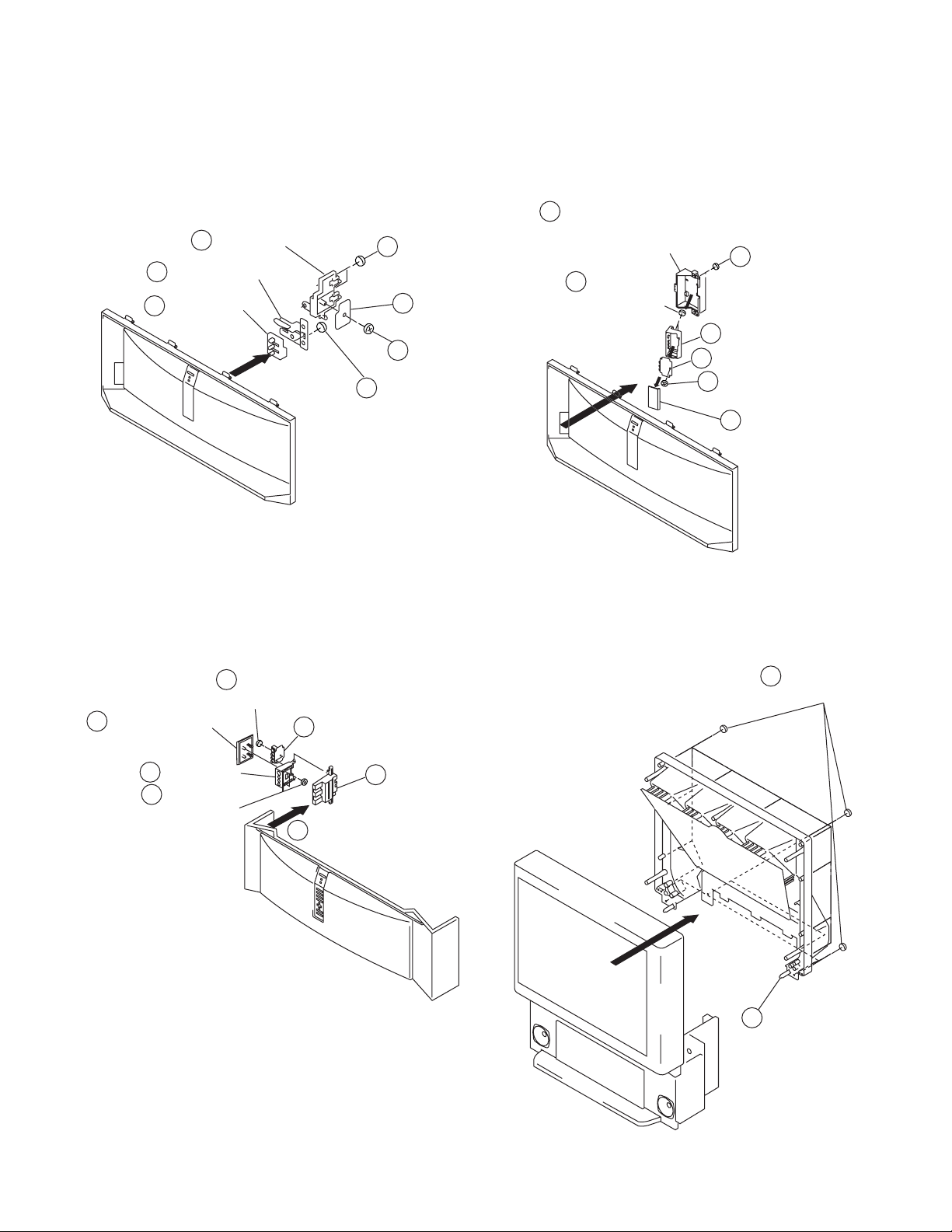
2-13. A BOARD, D BOARD AND U BOARD REMOVAL
4 Screws
(+BVTP3x12)
6 A board
4 Six screws
(+BVTP3x12)
6 D board
Main bracket
3 U board
2 Terminal board
1 Two screws
(+BVTP3x12)
5 Claws
2-15-. HIGH-VOLTAGE CABLE INSTALLATION AND
REMOVAL
1 Five screws
(+BVTP3x12)
(1) Removal
1 Rubber cap
2 HV cable
turn 90¡
(2) Installation
1 HV cable
Hook
2-14. PICTURE TUBE REMOVAL
CAUTION: Removing the arrow-marked
screws is strictly prohibited.
If removed, it may cause liquid spill.
Lens
Picture tube
2 Four screws
(Screw (4x20),
tapping)
3
4 Four screws
(Screw (4x20), tapping)
5 Lens
12 Four screws (+BVTP 4x12
13 Picture tube
10 Deflection yoke
7 Neck assy
6 CR board
1 Four screws
(Screw (4x20), tapping)
9 V board
8 Two screws (+BVTP
Gutter
– 11 –
SECTION 3
SET-UP ADJUSTMENTS
KP-43HT20C/53HS30C
RM-Y908RM-Y908
3-1. SCREEN VOLTAGE ADJUSTMENT (COARSE ADJUSTMENT)
1. Receive the Monoscope signal.
2. Set 50% BRIGHTNESS and minimum PICTURE.
3. Turn the red VR on the FOCUS block all the way to the left
and then gradually turn it to the right until the point where you
can see the retrace line.
4. Next gradually turn it to the left to the position where the
retrace line disappears.
R G B
SCREEN
R G B
FOCUS
FOCUS block
Fig. 3-1
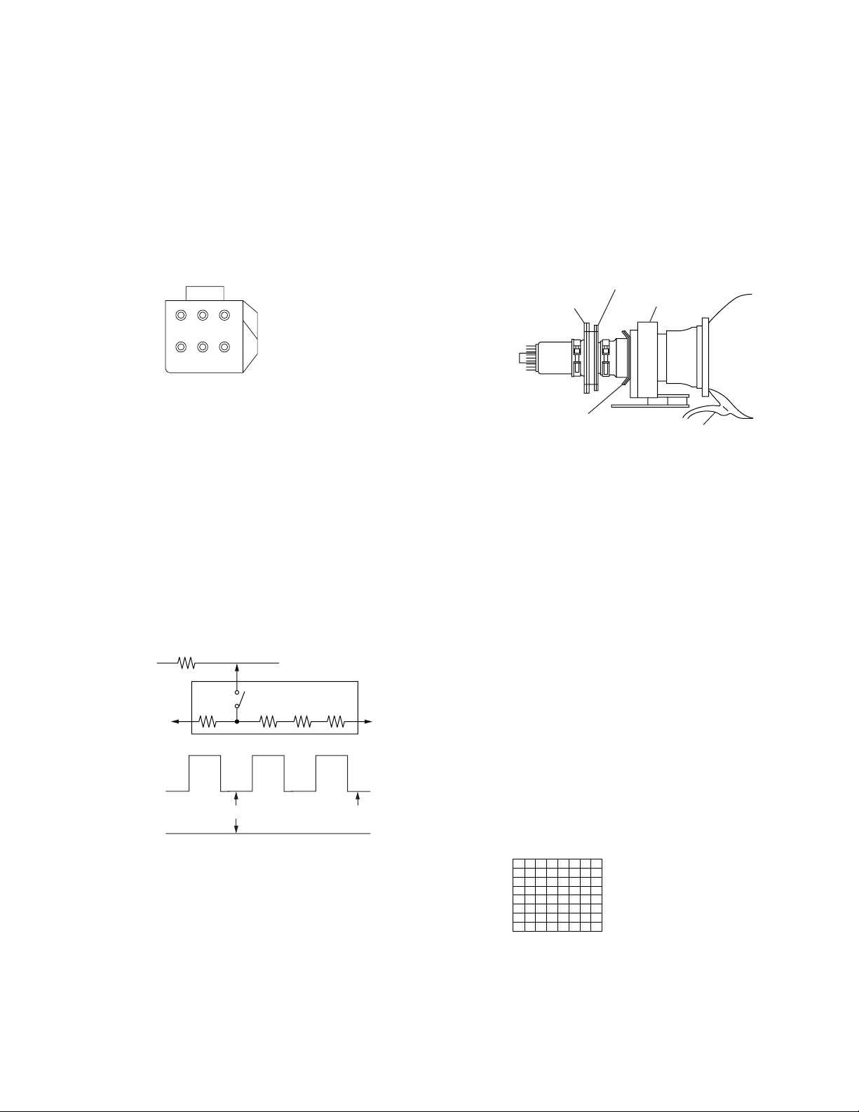
3-2. SCREEN (G2) ADJUSTMENT (FINE ADJUSTMENT)
Fine Mode is recommended to set screen controls to their optimal
condition. It is necessary to build the simple jig, illustrated below,
using 3-watt resistors. Please note, that if the proper voltage is
not obtained with their listed values, resistors, then please increase
or decrease one of the values in the resistor network to obtain the
correct voltage.
1. Select VIDEO1 mode without signals.
2. Connect G2 JIG.
3. SW on JIG.
4. Connect an oscilloscope to the TP7101(KR), TP7202(KG) and
TP7301(KB) of CR board, CG board and CB board.
5. Adjust R, G and B screen voltage to 170 ± 0.5V with screen
VR on the Focus block.
K
G2 JIG
O CG BOARD
TP7201
(200V)
3k 5.6k 5.6k 5.6k
SW
GND
All resistors are 3W type
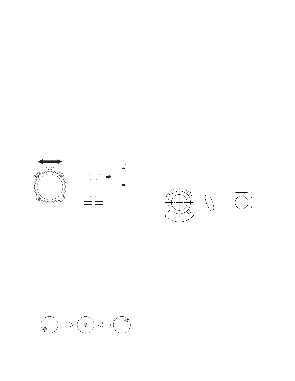
5. The tilt of the defl ection yoke for red is aligned in the mode
Cover the both green and blue picture lenses with the lens caps
and the tilt of the defl ection yoke for blue is aligned with in the
mode Cover the both green and red picture lenses with the lens
caps is aligned the same as was done for green.
Note: Instead of items 2 and 5, you can cut off the unnecessary
color beams by controlling the service mode CXA2150P-2 0
RGBS.
2-pole magnet
4-pole magnet
Deflection yoke
Fig. 3-3
Centering magnet
Anode cap
3-4. FOCUS LENS ADJUSTMENT
In this adjustment, use the remote commander in the service
mode.
For details of the usage of the service mode and the
remote commander, please refer the item 3-9. ELECTRICAL
ADJUSTMENT BY REMOTE COMMANDER.
1. Loosen the lens screw.
2. Cover the both red and blue picture lenses with the lens caps to
show only the green color.
3. Turn the green lens to adjust to the optimum focus point with
the crosshatch signal.
4. Tighten the lens screw.
5. Cover the both green and blue picture lenses with the lens caps
to show only the red color.
6. Adjust red CRT lens just the same as green.
7. Cover the both green and red picture lenses with the lens caps
to show only the blue color.
8. Adjust blue CRT lens just the same as green.
9. After adjusting the items 3-5. Focus VR Adjustment, 3-6.
2-Pole Magnet Adjustment and 3-7. 4-Pole Magnet Adjustment, adjust again to the optimum focus point.
170 ± 0.5V
GND
pedestal level
Fig. 3-2
3-3. DEFLECTION YOKE TILT ADJUSTMENT
1. Connect the color bar generator monoscope pattern to Video
1 input.
2. Cov er the both red and blue picture lenses with the lens caps to
show only the green color.
3. Loosen the defl ection yoke set screw and align the tilt of the
Defl ection Yoke so that the bars at the center of the monoscope
pattern are horizontal.
4. After aligning the defl ection yoke, fasten it securely to the
funnel-shaped portion (neck) of the CRT.
*: Every time you press 6, the test signal changes to
“crosshatch+video signal” - “crossbatch+borderline(black)”
- “crosshach(black)” - “dots(black)” - off.
Fig. 3-4
Test signal
Note: Instead of items 2, 5 and 7, you can cut off the unnecessary
color beams by controlling the service mode CXA2150P-2 0
RGBS.
– 12 –
KP-43HT20C/53HS30C
RM-Y908RM-Y908
3-5. FOCUS VR ADJUSTMENT
1. Set generator to crosshatch.
2. Cover the both red and blue picture lenses with the lens caps to
show only the green color.
3. Turn the green focus VR on the focus block to adjust to the
optimum focus point with the crosshatch signal.
4. Cover the both green and blue picture lenses with the lens caps
to show only the red color.
5. Turn the red focus VR on the focus block to adjust to the
optimum focus point with the crosshatch signal.
6. Cover the both green and red picture lenses with the lens caps
to show only the blue color.
7. Turn the blue focus VR on the focus block to adjust to the
optimum focus point with the crosshatch signal.
8. After adjusting the items 3-4. Focus Lens Adjustment, 3-6.
2-Pole Magnet Adjustment and 3-7. 4-Pole Magnet Adjustment, adjust again to the optimum focus point.
Note: Instead of items 2, 4 and 6, you can cut off the unnecessary
color beams by controlling the service mode 2150P-2 1 RGBS.
Scanning line visible.
A
Minimize both A and B.
Lens
Fig. 3-5
B
Center of crosshatch
Fig. 3-6
3-7. CENTERING MAGNET ADJUSTMENT
1. Set the picture mode to “Pro”.
2. Receive the monoscope signal.
3. Cov er the both red and blue picture lenses with the lens caps to
show only the green color.
4. Adjust the green centering magnet to put the center of the
monoscope signal to the center of the screen.
5. Adjust the red centering magnet in the same way.
6. Adjust the blue centering magnet in the same way.
Note: Instead of item 2 you can cut off the unnecessary color
beams by controlling the service mode 2150P-2 1 RGBS.
3-8. 4-POLE MAGNET ADJUSTMENT
1. Set the picture mode to“Pro” and picture to MAX.
2. Receive the Dot signal.
3. Cov er the both red and blue picture lenses with the lens caps to
show only the green color.
4. Turn the green focus VR on the focus block to the right and set
the spot will become smaller.
5. Adjust the 4-Pole Magnet so that the spot becomes round for
green and red.
6. Adjust blue spot to an oval shape X:Y=1:1.4 ~ 1.5.
Note: Instead of item 2 you can cut off the unnecessary color
beams by controlling the service mode 2150P-2 1 RGBS.
Use the center dot
x
/
x : y = 1:1.4
x : y = 1:1 (Green, Red)
y
1.5 (BIue)
˜
3-6. 2-POLE MAGNET ADJUSTMENT
1. Set the picture mode to“Pro” and picture to MAX.
2. Receive the Dot signal.
3. Cov er the both red and blue picture lenses with the lens caps to
show only the green color.
4. Turn the green focus VR on the focus block to the left and set
to overfocus to enlarge the spot.
5. Adjust 2-pole magnet so that the bright spot should be centered.
6. Align the green focus VR and set for just (precise) focus.
7. Perform the same alignment for red and blue.
Note: Instead of item 2 you can cut off the unnecessary color
beams by controlling the service mode 2150P-2 1 RGBS.
Fig. 3-7
Fig. 3-8
3-9. DEFOCUS ADJUSTMENT (BLUE)
Note: Please adjust the blue dot to be slightly larger than red and
green dots. This adjustment provides a more pleasing picture
to the customer.
1. Select the picture mode to “Pro”.
2. Receive the Dot signal.
3. Cover the both red md green picture lenses with the lens caps
to show only the blue color.
4. Turn the blue focus VR on the focus block to right to make
the round dot elipical.
5. Check fl are with high luminace signal, make sure fl are is
minimal while dot shape is elipical.
6. Set generdtor to all white signal and check uniformity.
Note: Instead of item 3 you can cut off the unnecessary color
beams by controlling the service mode 2150P-2 1 RGBS.
– 13 –
KP-43HT20C/53HS30C
RM-Y908RM-Y908
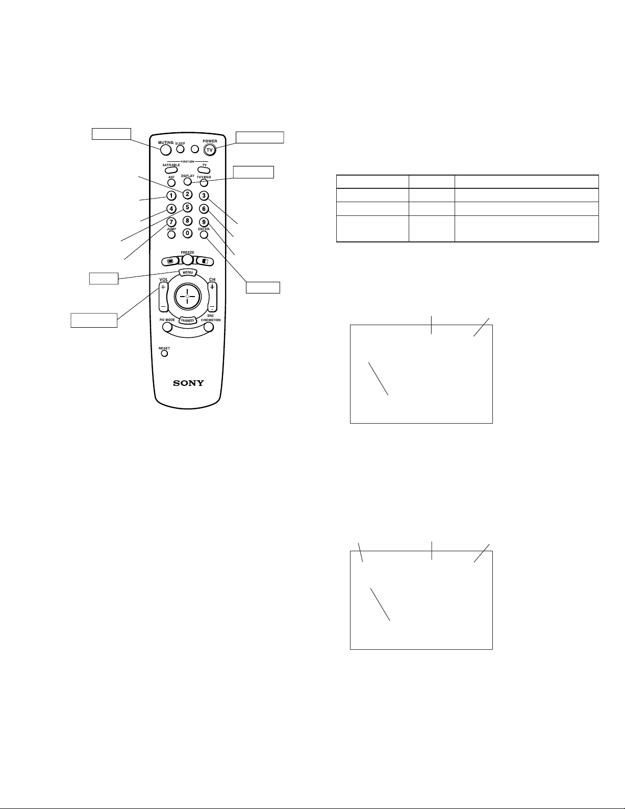
3-10.ELECTRICAL ADJUSTMENT BY REMOTE
COMMANDER
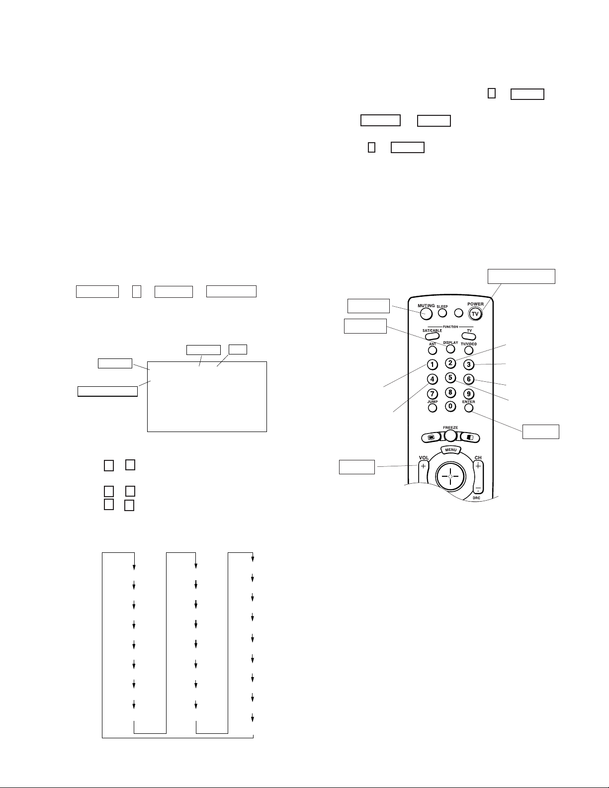
By using Remote Commander (RM-Y908),all circuit adjustments
can be made.
NOTE : Test Equipment Required.
1. Pattern Generator (with component outputs)
2. Frequency counter
3. Digital multimeter
4. Audio oscillator
1. METHOD OF SETTING THE SERVICE ADJUSTMENT
MODE
SERVICE MODE PROCEDURE
1. Standby mode. (Power off)
2. DISPLAY ! 5 ! VOL (+) ! TV POWER
on the Remote Commander.
(Press each button within a second.)
Data
SERVICE
TV
Category
Adjustment Item
Item NO.
3D-COMB
NRMD
F / A FLAG : XXXXXXXX
CBA FLAG : XXXXXXXX
0 0
WSL : XXX
7. If you want to recover the latest values press 0 then ENTER to
read the memory.
8. Press MUTING then ENTER to write into memory.
9. Turn power off.
Note: Press 8 then ENTER on the Remote Commander to initialize or
turn set off and on to exit.
2. MEMORY WRITE CONFIRMATION METHOD
1. After adjustment, turn power off with the remote commander.
2. Turn power on and set to Service Mode.
3. Call the adjusted items again and confi rm they were adjusted.
3. ADJUSTING BUTTONS AND INDICATOR
TV POWER ON
MUTING
DISPLAY
Category up
Data up
Adjustment item up
Adjustment item down
Data down
Category down
ENTER
3. The SCREEN displays the item being adjusted.
4. Press 1 or 4 on the Remote Commander to select the
adjustment item.
5. Press 3 or 6 on the Remote Commander to change the data.
6. Press 2 or 5 on the Remote Commander to select the
category.
Every time you press 2(Category up), Service mode changes in
the order as shown below.
3D-COMB
2103-1
2103-2
2150P-1
2150P-2
2150P-3
2150P-4
2150D-1
2150D-2
2150D-3
2151
AP
TRUS
DLBY
MID1
MID2
MID3
MID5
OSD
SNNR
ID-1
CCD
PJE
OP
ID
VOL (+)
RM-Y908
Note : When the PJE mode is activated, which displays an inter-
nally generated signal, several buttons on the remote commander will have different functions than listed above.
Therefore, when in the PJE mode, refer to page 26 for
button functions.
– 14 –
KP-43HT20C/53HS30C
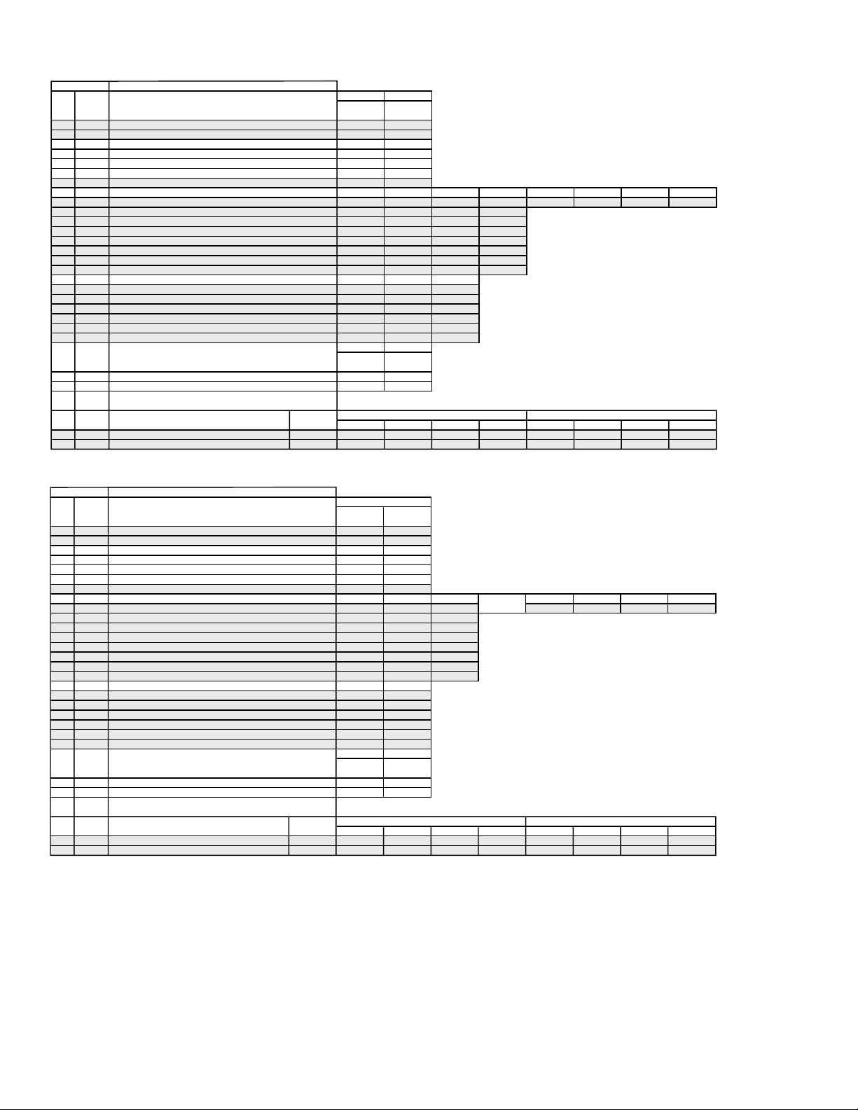
4. SERVICE MODE LIST
Note: • shaded items are fi xed. There is no need to change data. Others are different a little in
the sets individually. Basically, there is no need to change data, too.
3D-COMB uPD64082
Reg.No & Name FUNCTION
0 NRMD Operation mode setting 0133
1 YAPS Y-output correction 3 *
2 CLKS System clock setting 1 *
3 NSDS Selection for standard/non-standard signal processing 0000
4 MSS Selection for inter-frame/inter-line processing 0 *
5 KILS Killer processing selection 1 *
6 CDL C-signal phase with respect to the Y-signal 3 3
7 DYCO DY detection coring level (Y motion detection coring) 2222
8 DYGA DY detection gain (Y motion detection gain) 10 10 10 10
9 DCCO DC detection coring level (C motion detection coring) 5555
10 DCGA DC detection gain ( C motion detection gain) 5555
11 YNRL Frame recursive YNR nonlinear filter limit level 1 *
12 CNRL Frame recursive CNR nonlinear filter limit level 1 *
13 VTRH Hysteresis for Hsysnc non-standard signal detection 1 1 1
14 VTRR Sensitivity for Hsysnc non-standard signal detection 1 1 1
15 LDSR Sensitivity for frame non-standard signal detection 2 2 2
16 VAPG V-aperture compensation gain 0000
17 VAPI V-aperture compensation convergence point 0000
18 YPET Y peaking filter (BPF) center frequency 30000
19 YPFG Y peaking filter (BPF) gain 80123
20 YHCO Y output high frequency component coring 0111 Note: YHCO & YHCG are defined directly by SNNR data.
21 YHCG Y output high frequency component coring gain 1111
22 HSSL Hsync slice level 12 *
23 VSSL Vsync slice level 8 *
24 ADCL ADC clock delay 3 *
25 D2GA Moving detection gain 4444
26 KILR Killer detection reference 3 *
UHF/VHF & Cvideo Svideo Note: * shows common data.
Standard Non-standard Standard Non-standard
UHF/VHF & Cvideo Svideo
Standard Non-standard Standard Non-standard
UHF/VHF CV/SV
NRMD=0 NRMD=1 NRMD=2 NRMD=3
UHF/VHF Video1-4 Video5&6
VM=off VM=Low VM=Mid VM=High
SNNR=0 SNNR=1 SNNR=2 SNNR=3
SNNR=0 SNNR=1 SNNR=2 SNNR=3
NRMD=0 NRMD=1 NRMD=2 NRMD=3
RM-Y908RM-Y908
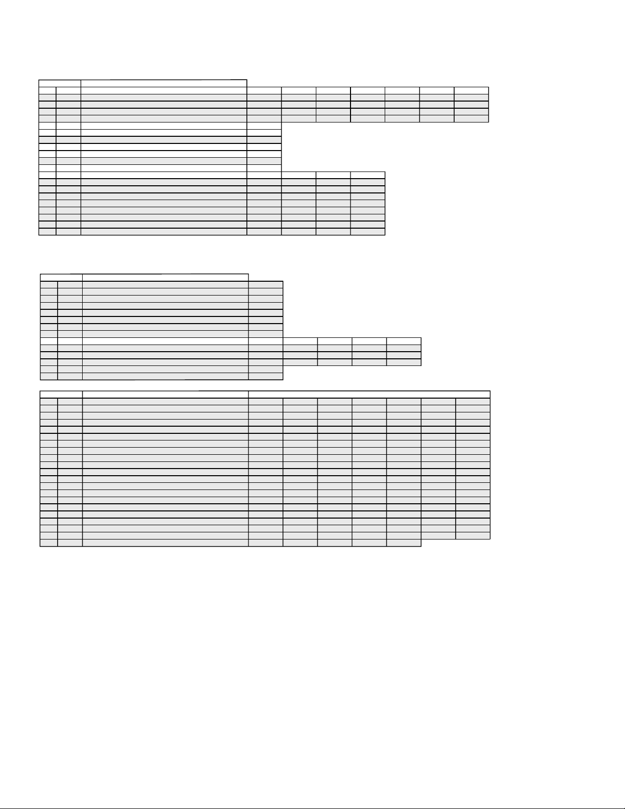
3D-COMB uPD64082
Reg.No & Name FUNCTION
27 OP Option: Selection of comb filter&recursive n.reduction types. 1 *
28 NR1 Noise reduction on/off 0 0 101010
29 NR2 SNNR control on/off 0 *
30 WSL Noise level detection level data 0-255 Read Data
31 HPLL H-PLL filter 1 *
32 BPLL Burst PLL filter 1 *
33 FSCF Burst extraction gain 0 *
34 PLLF PLL loop gain 1 *
35 CC3N Selection if a line-comb filter C separation filter characteristic 0 0 0
36 HDP Fine adjustment of the system H-phase 5 *
37 BGPS Internal 4*
38 BGPW 10 *
39 TEST Test bit (0:Normal mode 1:Test mode) * forbidden setting 0 *
40 WSC Amount of noise detection coring 1 *
41 LIND DRC-M line-doubling setting for non-standard signals UHF/VHF&Video1-4 0 2
42 PFGO (YPFG offset at GR on) * Not used 3 *
#16 VAPG 0000
UHF/VHF CVideo1 SVideo1 CVideo2 SVideo2 CVideo3 SVideo3 CVideo4
UHF/VHF Video1-4 Video5&6
UHF/VHF & Video1-4 Video5&6
SNNR=0 SNNR=1 SNNR=2 SNNR=3
– 15 –
KP-43HT20C/53HS30C
NTSC-YCT (Chroma Decoder) CXA2103-1 (Main)
Reg.No & Name FUNCTION
0 YLEV Y-Out gain 34 40
1 CLEV Cb&Cr-Out gain 27 46
2 SCON Sub contrast ADJ (7) ADJ (7)
3 SCOL Sub color ADJ (7) ADJ (7)
4 SHUE Sub hue ADJ (7) ADJ (7)
5 YDLY Y/C delay time 0 0
6 SHAP Sharpness 54440123
7 SHF0 Sharpness f0 selector 3333
8 PREO Sharpness pre/over-shoot ratio 3000
9 BPF0 Chroma band filter f0 setting 3000
10 BPFQ Chroma band filter Q setting 0333
11 BPSW Chroma bnad filter on/off 1000
12 TRAP Y block chroma trap filter on/off 0000
13 LPF Y Cb Cr-Output LPF on/off 1111
14 AFCG AFC Loop gain (PLL between Hsync & HVCO) 1 0 0
15 CDMD V countdown system mode selector 3 3 3
16 SSMD H&Vsync slide level setting 0 0 0
17 HMSK Masking of macrovision signal on/off 1 1 1
18 HALI H automatic adjustment on/off 0 0 0
19 PPHA H TIM phase adjustment video 7 7 7
20 CBOF 34 34
21 CROF 32 32
UV & Video YCbCr-480i
P&P Left P&P Left
(M)-DRC (M)-DRC
UHF/VHF Video
UHF/VHF Cvideo Svideo YCbCr480i SNNR=0 SNNR=1 SNNR=2 SNNR=3
UHF/VHF Video YCbCr
UV & Video YCbCr-480i
P&P Left P&P Left
(M)-DRC (M)-DRC
RM-Y908RM-Y908
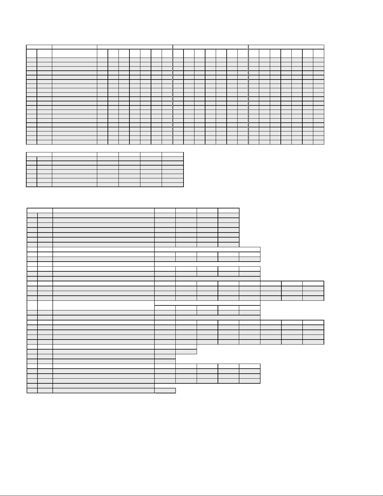
22 ATPD Auto-pedestal Inflection Point P&P & Favorite UBLK=0 011211232
23 DCTR DC Transmission Ratio P&P & Favorite UBLK=0 021122223
NTSC-YCT (Chroma Decoder) CXA2103-2 (Sub)
Reg.No & Name FUNCTION
0 YLEV Y-Out gain 34 38
1 CLEV Cb&Cr-Out gain 27 31
2 SCON Sub contrast ADJ (7) ADJ (7)
3 SCOL Sub color ADJ (7) ADJ (7)
4 SHUE Sub hue ADJ (7) ADJ (7)
5 YDLY Y/C delay time 0 0
6 SHAP Sharpness 444 0123
7 SHF0 Sharpness f0 selector 3 3 3
8 PREO Sharpness pre/over-shoot ratio 0 0 0
9 BPF0 Chroma band filter f0 setting 0 0 0
10 BPFQ Chroma band filter Q setting 0 0 0
11 BPSW Chroma bnad filter on/off 0 0 0
12 TRAP Y block chroma trap filter on/off 0 0 0
13 LPF Y Cb Cr-Output LPF on/off 0 0 0
14 AFCG AFC Loop gain (PLL between Hsync & HVCO) 1 0 Note: Reg.No 14 to 19 are the same data as CXA2103-1. (the same NVM address)
15 CDMD V countdown system mode selector 3 3
16 SSMD H&Vsync slide level setting 0 0
17 HMSK Masking of macrovision signal on/off 1 1
18 HALI H automatic adjustment on/off 0 0
19 PPHA H TIM phase adjustment video 7 7
20 CBOF 32 32
21 CROF 31 31
22 ATPD Auto-pedestal Inflection Point P&P & Favorite UBLK=0 0 1 1 2 1 1 2 3 2
23 DCTR DC Transmission Ratio P&P & Favorite UBLK=0 0 2 1 1 2 2 2 2 3
Single Picture UBLK-0 UBLK-1 UBLK-2 UBLK-3 UBLK-4 UBLK-5 UBLK-6 UBLK-7
UV & Video
P&P Right P&P Right
(S) (S)-DRC
UHF/VHF Video
UHF/VHF Cvideo Svideo SNNR=0 SNNR=1 SNNR=2 SNNR=3
UHF/VHF Video
UV & Video YCbCr-480i
P&P Right P&P Right
(S) (S)-DRC
Single Picture UBLK-0 UBLK-1 UBLK-2 UBLK-3 UBLK-4 UBLK-5 UBLK-6 UBLK-7
Note: Reg.No 22 and 23 are the same data as CXA2103-1. (the same NVM address)
P&P & Favorite P&P & Favorite
Note: Sub signal goes through DRC, when main signal is 480p, 1080i, or 720p
P&P & Favorite P&P & Favorite
– 16 –
KP-43HT20C/53HS30C
CRT Driver CXA2150P-1 (Picture Controls:P1)
Reg.No & Name FUNCTION
0 SBOT Offset for SBRT 0007777
1 YOF Y OFFSET: DC-offset for Y signal 0000000
2 CBOF CB OFFSET: DC-offset for Cb signal 35 35 35 37 40 31 35
3 CROF CR OFFSET: DC-offset for Cr signal 36 36 36 39 41 31 36
4 SBRT SUB BRT: Sub Bright ADJ (24) *
5 RDRV R DRIVE: R output drive ADJ (31) *
6 GDRV G DRIVE: G output drive 31 *
7 BDRV B DRIVE: B output drive ADJ (31) *
8 RCUT R CUTOFF: R output cutoff ADJ (31) *
9 GCUT G CUTOFF: G output cutoff 31 *
10 BCUT B CUTOFF: B output cutoff ADJ (31) *
11 WBSW WB SW 0 (no memory) 0 (no memory) 0 (no memory) 0 (no memory)
12 SBOF Offset for SBRT 63 63 (no memory) 63 63 (no memory)
13 RDOF Offset for RDRV 63 63 (no memory) 65 63 (no memory)
14 GDOF Offset for GDRV 63 63 (no memory) 63 63 (no memory)
15 BDOF Offset for BDRV 66 63 (no memory) 54 63 (no memory)
16 RCOF Offset for RCUT 62 63 (no memory) 63 63 (no memory)
17 GCOF Offset for GCUT 63 63 (no memory) 63 63 (no memory)
18 BCOF Offset for BCUT 67 63 (no memory) 62 63 (no memory)
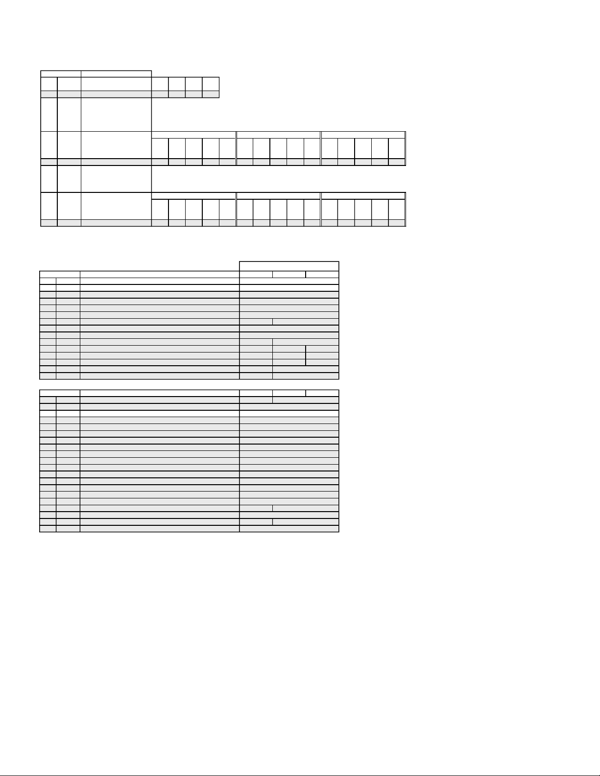
CRT Driver CXA2150P-2 (Picture Controls:P2)
Reg.No & Name FUNCTION
0 ALBK PIC ON 1*
1 RGBS R ON/G ON/B ON : R/G/B outputs on/off 7 *
2 BLKB BLK BTM: RGB output bottom limit level (Black level) 3 *
3 LIML PLIMIT LEV: Threshold level for excessively high inputs 0 *
4 PABL P ABL: DC-level in RGB output detection for PEAK ABL 15 *
5 SABL S ABL: S ABL gain 0 *
6 AGNG AGING W/AGING B: AGING W/AGING B modes on/off 0 *
7 AKBO AKBOFF: Automatic/Manual = Cut off setting 0 *
8 SYPH SYNC PHASE: Hsync delay with respect to Video (100%H-period) 00000
9 CLPH CLP PHASE: Internal clamp pulse phase (100%H-period) 33333
10 CLGA CLP GATE: Switch for the gated internal clamp pulse with Hsync 00000
11 JAXS JAXIS: color axis switch 0 *
12 BLKO BLKO: Blanking switch 0 *
CRT Driver CXA2150P-3 (Picture Controls:P3) (Part1)
Reg.No & Name FUNCTION Vivid
0 SYSM SYSTEM: Signal bandwidth setting 1111122
1 UVML VM LEV: VM OUT level 3332233
2 VMMO System Micro pin#40 1111110
3 VMCR VM COR: VM OUT coring level 0001133
4 VMLM VM LMT: VM OUT limit level 3333333
5 VMF0 VM F0: VM f0 2222222
6 VMDL VM DLY:VM OUT phase (defined by phase difference from R OUT) 1222201
7 SHOF Offset for USHP=SHOF x 4 0112333
8 SHF0 SHP F0: Sharpness circuit f0 1111101
9 PROV PRE/OVER: Y signal pre/over-shoot ratio 0003333
10 F1LV SHP F1: Sharpness for higher f0 (4.2/5.6Mhz @NORMAL mode) 0000133
11 CDSP SHP CD: Sharpness in part of high color saturation 3333333
12 LTLV LTI LEV: Luminance transient improvement (LTI) 3333333
13 LTMD LTI MODE: LTI mode setting 1111001
14 CTLV CTI LEV: Chrominance transient improvement (CTI) 0000000
15 CTMD CTI MODE: CTI mode setting 0000000
16 UBOF Offset for UBRT (Picture clarity adjustment) 0 0 0 0 7 9 7
17 UCOF Offset for UCOL=UCOF x 2 (Picutre clarity adjustment) 3333302
18 UHOF Offset for UHUE (Picutre clarity adjustment) 0000007
19 MIDE MID enhancement setting 3 15 15 7 11
UHF/VHF CV SV YCbCr480i YCbCr480P YCbCr1080i P&P
Vivid (Cool) Std (Neutral) Movie (Warm) Pro
UHF/VHF V1 _ 4
UHF/VHF CV SV YCbCr480i YCbCr480P YCbCr1080i P&P
YCbCr480i YCbCr480P YCbCr1080i P&P
RM-Y908RM-Y908
– 17 –
KP-43HT20C/53HS30C
CRT Driver CXA2150P-3 (Picture Controls:P3) (Part2)
Reg.No & Name FUNCTION Standard Movie Pro
#0 SYSM 111112211111221111122
#1 UVML 222222311111110000000
#2 VMMO 111111100000000000000
#3 VMCR 100113311111333333333
#4 VMLM 333333333333333333333
#5 VMF0 222222222222222222222
#6 VMDL 022221112222112222211
#7 SHOF 100023311111110000000
#8 SHF0 111111111111111111111
#9 PROV 030000033332233332322
#10 F1LV 000013300012330001233
#11 CDSP 333333300000000000000
#12 LTLV 222222200000000000000
#13 LTMD 111110111111011111101
#14 CTLV 000000000000000000000
#15 CTMD 000000000000000000000
#16 UBOF 7 77779777777777777777
#17 UCOF 111110000000000000000
#18 UHOF 000000000000000000000
#19 MIDE 2 14 14 6 10
CRT Driver CXA2150P-3 (Picture Controls:P3) (Part3)
Reg.No & Name FUNCTION
#1 UVML 0 0 0 0
#3 VMCR 0 +1 +2 +3
#10 F1LV 0 -1 -2 -3
#11 CDSP 0 0 0 0
#12 LTLV 0 0 0 0
#14 CTLV 0 0 0 0
#19 MIDE 0 0 0 0
UHF CV SV YCbCr YCbCr YCbCr P&P UHF CV SV YCbCr YCbCr YCbCr P&P UHF CV SV YCbCr YCbCr YCbCr P&P
VHF 480i 480P 1080i VHF 480i 480P 1080i VHF 480i 480P 1080i
--
SNNR=0 SNNR=1 SNNR=2 SNNR=3
113135 9
--
012124 8
--
RM-Y908RM-Y908
CRT Driver CXA2150P-4 (Picture Controls:P4)
Reg.No & Name FUNCTION Vivid Standard Movie Pro
0 UPIC PICTURE: Picture 63 44 31 31
1 UBRT BRIGHT: Brightness 26 31 31 31
2 UCOL COLOR: 31 31 31 31
3 UHUE HUE:Hu 31 31 31 31
4 USHP SHARPNESS: Sharpness 32 40 31 31
5 UTMP Color Temperature (0:Warm 1:Neutral 2:Cool) 2101
6 UDCL DCOL: D 2200
7 AXIS COL AXIS: color matrix setting 00000
8 UGAM GAMMA/GAMMA L: RGB output GAMMA correction setting 54415
9 AGAM GAMMA/GAMMA L (AV Pro user control) - Void Data -
10 GSBO Offset for SBRT 00000000
11 GCCO Offset for UCOL 00000000
12 GHUO Offset for UHUE 00000000
13 UBLK Item#15-18 pack F1 data controls 66664
14 ABLK (Av Pro user control) - Void Data
15 DCTR DC TRAN: Y signal DC transmission 11123333
16 DPIC DPIC LEV: Y signal AUTO PEDESTAL level 01211212
17 DSBO Offset for SBRT 77777777
18 ABLM ABL MODE: ABL mode 00000011
19 ABLT ABL TH: ABL current detection Vth contro 0 15
20 EPOF Offset for UPIC=EPOF x (UPIC/63) (for power save) - Void Data
21 SPOF Offset for UPIC=SPOF x (UPIC/64) - Data Not used 15 << Only available at Vcomp 1 & 2.
22 SCON SUB CONTRAST: SUB PICTURE 8 5544
23 CLOF Offset for UCOL 99999
24 HUOF Offset for UHUE 55555
25 IDSW Not used
UHF/VHF V1-4
UHF/VHF V1-4
UGAM-0 UGAM-1 UGAM-2 UGAM-3 UGAM-4 UGAM-5 UGAM-6 UGAM-7
UHF/VHF V1-4
UBLK0 UBLK1 UBLK2 UBLK3 UBLK4 UBLK5 UBLK6 UBLK7
UHF/VHF V1-4
26 DATA Display of vertical compression modes. Not used. 0
YCbCr480i YCbCr480P YCbCr1080i P&P
Picture Mode Vivid
YCbCr480i YCbCr480P YCbCr1080i P&P
Picture Mode Vivid
YCbCr480i YCbCr480P YCbCr1080i P&P
-
Full Vcomp 1 & 2
YCbCr480i YCbCr480P YCbCr1080i P&P
– 18 –
CRT Driver CXA2150P-4 (Picture Controls:P4)
Reg.No & Name FUNCTION
#4 USHP 0134
#8 UGAM 222110000000000
#13 UBLK 333331111100000
SNNR SNNR SNNR SNNR
=0 =1 =2 =3
Picture Mode : Standard Picture Mode : Movie Picture Mode : Pro
UHF YCbCr YCbCr YCbCr P&P UHF YCbCr YCbCr YCbCr P&P UHF YCbCr YCbCr YCbCr P&P
VHF 480i 480P 1080i VHF 480i 480P 1080i VHF 480i 480P 1080i
V1 _ 4 V1 _ 4 V1 _ 4
Picture Mode : Standard Picture Mode : Movie Picture Mode : Pro
UHF YCbCr YCbCr YCbCr P&P UHF YCbCr YCbCr YCbCr P&P UHF YCbCr YCbCr YCbCr P&P
VHF 480i 480P 1080i VHF 480i 480P 1080i VHF 480i 480P 1080i
V1 _ 4 V1 _ 4 V1 _ 4
KP-43HT20C/53HS30C
RM-Y908RM-Y908
CRT Driver CXA2150D-1 (Deflection Controls:D1)
Reg.No & Name FUNCTION
0 VPOS V POSITION: Vertical position (V DRV signal DC bias)
1 VSIZ V SIZE: Vertical size (V DRV signal gain) ADJ (50)
2 VSZO V SIZE OFFSET 0
3 VLIN V LINEARITY: Vertical linearity 5
4 VSCO S CORRECTION: Vertical S-correction 8
5 VCEN VSAW0 DCH/VSAW0 DCL: Vertical center adjustment 31
6 VPIN VSAW0 AMP: Vertical PIN adjustment 15 15
7 NSCO VSAW1 DC: Rotation 7
8 HTPZ VSAW1 AMP: Horizontal trapezoid 15
9 ZOOM ZOOM SW: Zoom switch 0 0
10 APSW ASP SW: Aspect switch 0 1 0
11 ASPT V ASPECT: Aspect ratio 44 32 28
12 SCRL V SCROLL: Vertical scroll 29 29 29
13 UVLN UP VLIN: Upper vertical linearty 0 0
14 LVLN LO VLIN: lower vertical linearty 0 0
CRT Driver CXA2150D-2 (Deflection Controls:D2)
Reg.No & Name FUNCTION
0 HCNT HC PARA DC: Horizontal center 19 19
1 HPOS H POSTION: Horizontal position 25
2 HSIZ H SIZE: Horisontal size
3 SLIN MP PARA DC: Horizontal S-correction 3
4 MPIN MP PARA AMP: Horizontal middle pin 7
5 PIN PIN AMP: Horizontal pin 10
6 PIN0 7
7 UCP UP CPIN: Upper corner pin 31
8 LCP LO CPIN: Lower corner pin 31
9 UXCG UP UCG: Upper extra corner pin gain 0
10 LXCG LO UCG: Lower extra corner pin gain 0
11 UXCP UP UCP: Upper extra corner pin position 2
12 LXCP LO UCP: Lower extra corner pin position 2
13 XCPP UC POL: Extra corner pin polarity 0
14 PPHA PIN PHASE: Pin phase 31
15 VANG AFC ANGLE: AFC angle 31
16 LANG HC PARA PHASE: Linearity angle 31 33
17 VBOW AFC BOW: AFC bow 31
18 LBOW HC PARA AMP: Linearity bow 39 63
19 CPY1 Copy function 1: (Set CPY1=1, then press MUTE+Enter) * Not used 0
Full Vcomp1 Vcomp2
Full Vcomp1 Vcomp2
4:3
ADJ (31)
ADJ (30)
– 19 –
CRT Driver CXA2150D-3 (Deflection Controls:D3)
Reg.No & Name FUNCTION
0 HBLK HBLK SW: Horizontal blanking switch 1
1 LBLK LEFT BLK: Left blanking 56 56
2 RBLK RIGHT BLK: Right blanking 25 25
3 VBLK VBLK SW: Vertical blanking switch 1 1
4 TBLK UP BLK: Top blanking 15 14 12
5 BBLK LO BLK: Bottom blanking 15 15 13
6 VCMP V COMP: Vertical compensation 0 3 3
7 HCMP H COMP: Horizontal compensation 0 0
8 ACMP AFC COMP: AFC compensation 0 0
9 PCMP PIN COMP: Pin compensation 0 0
10 AFCM AFC MODE: AFC compensation 3 2
11 VFRQ V FREQ: Vertical frequency 1
12 VON V ON: Vertical drive on 1
13 JUMP JMP SW: Reference pulse jump switch 0 1
14 VDJP VDRV SW: Vertical drive switch 1 1 1
15 VDST RST SW: Vertical drive start switch 0 0 0
16 EWDC EW DC: Pin DC level shift 0 0
17 AKBT AKBTIM: AKB timing 9 9 9
Full Vcomp1 Vcomp2
KP-43HT20C/53HS30C
RM-Y908RM-Y908
Component I/F & Sync Separation CXA2151
Reg.No & Name FUNCTION
0 MTRX MAT OUT 0011
1 GAIN GAIN SEL 0
2 CBGN CBGAIN 9
3 VTC V TC 1
4 HWID H WIDTH 1
5 HSEP HSEP SEL 000
6 TEST TEST 0
7 FRGB 0
8 HMSK Hsync masking in vertical retrace 1 0
Audio Processor (AP) BH3868FS
Reg.No & Name FUNCTION
0 SVOL Volume:Offset for Volume 0
1 SBAL Balance Offset for Balance 7
2 SBAS Bass:Offset for Bass 10
3 STRE Treble:Offset for Treble 7
4 BBLP BBE low pass filter 0
5 BBHP BBE high pass filter 2
6 SREF Surround effect 11
7 AGC Auto gain control 0
8 BBE BBE on/off 0
TruSurround (TRUS) NJM2180
Reg.No & Name FUNCTION
1 TSMD Trusurround effect selection 2
0 ATT 0
DLBY NJM1106
Reg.No & Name FUNCTION
0 DBMD 0
1 SCH 0
2 ADSW 0
3 CECH 0
4 DELY 0
5 SSEL
480i 480P 1080i 720P
15.75khz 31.50khz 33.75khz 45khz
Video5 Video6 Sub
Full Vcomp1 Vcomp2
0
– 20 –
MID-1 (Display Data : Output)
Reg.No & Name FUNCTION
(A) Display Data (Only One) (for 4:3)
0 DHPH H active display area phase 110
1 DVPH V active display area phase 20
2 DHAR H active display area size 240
3 DVAR V active display area size 135
4 DHPW display H pulse width 55
5 DVPW display V pulse width 5
22 DPSW display PLL switch 1 (fixed)
23 MDL model select (16:9/4:3) 0
(B) Misc. Common Data Data
6 DYCD display output Y-C delay correction 2
7 DYSD display output YS signal delay select 1
(C) Favorite / Other Favorite Others
8 MDHP main display picture H position 9 0
10 MDHS main display picture H size 149 240
(D) Single (Input Signal Format) / Favorite Single 480i/480P Single 720P Favorite
9 MDVP main display picture V position 30 30 20
11 MDVS main display picture V size 120 120 97
(E) Index / Others Index Others
12 MLHP multi picture mode H position 36 36
13 MLVP multi picture mode V position 31 31
(F) Favorite Favorite
14 SDHS sub display picture H position 166
15 SDVS sub display picture V position 20
(G) Favorite Favorite
16 SDHS sub display picture H size 44
17 SDVS sub display picture V size 29
(H) PinP Position (Not Used)
18 PDHP (PinP Large mode H position)
19 PDVS (PinP Large mode V position)
(I) PinP Size (Not Used)
20 PDHS (PinP Large mode H size)
21 PDVS (PinP Large mode V size)
(J) Single / Others Single Others
24 BCOL Background Y level 5 5
Normal
154
162
-
-
-
-
KP-43HT20C/53HS30C
RM-Y908RM-Y908
MID-2 (Active Data for DRC : INPUT))
Reg.No & Name FUNCTION
(A) MID Mode, Wide mode, Input Signal Format Single(Normal)
0 DRHP DRC H active area position 111 110
1 DRHS DRC H active area size 178 178
2 DRVP DRC V active area position 37 37
3 DRVS DRC V active area size 120 120
0 DRHP DRC H active area position 132 131 142 141
1 DRHS DRC H active area size 166 166 162 162
2 DRVP DRC V active area position 54 54 58 58
3 DRVS DRC V active area size 112 112 110 110
0 DRHP DRC H active area position 139 138 138 143
1 DRHS DRC H active area size 164 164 166 162
2 DRVP DRC V active area position 50 50 54 54
3 DRVS DRC V active area size 114 114 112 112
RF, Video, YC YPbPr
Twin, Favorite Memo
RF, Video, YC YPbPr RF, Video, YC YPbPr
RF, Video, YC YPbPr RF, Video, YC RF
Index Twin-Right Index-Small
Single(Other)
RF, Video, YC YPbPr
111 110
178 178
37 37
120 120
– 21 –
MID-3 (Active Data for A/D (VDO) : INPUT)
Reg.No & Name FUNCTION
(A) MID mode, Wide mode, Input Signal Format Single
0 VDHP VDO H active area position 109 95 205
1 VDHS VDO H active area pixel size 166 108 226
2 VDVE VDO V active area even position 37 24 37
3 VDVS VDO V active area line size 120 180 56
0 VDHP VDO H active area position 128 94 111 179 197
1 VDHS VDO H active area pixel size 155 150 99 199 215
2 VDVE VDO V active area even position 53 37 50 24 26
3 VDVS VDO V active area line size 112 126 168 56 56
0 VDHP VDO H active area position 136 102 115 179
1 VDHS VDO H active area pixel size 152 147 98 199
2 VDVE VDO V active area even position 57 44 58 24
3 VDVS VDO V active area line size 110 123 164 56
0 VDHP VDO H active area position 132 99 112 166 204
1 VDHS VDO H active area pixel size 154 149 99 187 211
2 VDVE VDO V active area even position 51 34 48 24 26
3 VDVS VDO V active area line size 113 128 169 56 56
(B) Input Signal Format
4 VDVO VDO V active area line size 0 0 0 0
5 VCPO VDO V active area odd position 95 70 40 40
6 VCWD VDO clamp pulse output timing 3 3 3 3
7 VYCD VDO clamp pulse width 0 0 0 0
8 VSTP VDO PLL phase ditect stop line count
9 VSTT VDO PLL phase ditect start line count
10 VHSC VDO H sync cycle 130
480P 720P YPbPr No Signal
480P 1080i 720P YPbPr No Signal RF, Video, S-Video
480P 1080i 720P YPbPr No Signal
480P 1080i 720P YPbPr No Signal RF
RF, Video, S-Video, YPbPr 480i 480P 1080i 720P
-
-
Twin, Favorite Twin-Right
Memo
Index Index-Small
119 160 146
400
---
KP-43HT20C/53HS30C
RM-Y908RM-Y908
MID-5 (Picture Data) (A) Enhance Table Data Setting
0 P-OP Table select 01234567
1 MHLY Main H LPF Y Coefficient select 11111111
2 MHLC Main H LPF C Coefficient select 33333333
3 MVLY Main V LPF Y Coefficient select 00000000
4 MVLC Main V LPF C Coefficient select 00000000
5 MHYR Main H Enhance. Y Coreing level 11210001
6 MHYL Main H Enhance. Y Clip level 11111111
7 MHYE Main H Enhance. Y Enhancement level 77337735
8 MHYO Main H Enhance. Y Coefficient select 11111111
9 MHCR Main H Enhance. C Coreing level 00000000
10 MHCL Main H Enhance. C Clip level 11111111
11 MHCE Main H Enhance. C Enhancement level 00000000
12 MHCO Main H Enhance. C Coefficient select 11111111
13 MVYR Main V Enhance. Y Coreing level 00220022
14 MVYL Main V Enhance. Y Clip level 11101111
15 MVYE Main V Enhance. Y Enhancement level 00250025
16 MVCR Main V Enhance. C Coreing level 00000000
17 MVCL Main V Enhance. C Clip level 11111111
18 MVCE Main V Enhance. C Enhancement level 00000000
0 P-OP Table select 8 9 10 11 12 13 14 15
1 MHLY Main H LPF Y Coefficient select 00001111
2 MHLC Main H LPF C Coefficient select 33333333
3 MVLY Main V LPF Y Coefficient select 00000000
4 MVLC Main V LPF C Coefficient select 00000000
5 MHYR Main H Enhance. Y Coreing level 00010001
6 MHYL Main H Enhance. Y Clip level 11111111
7 MHYE Main H Enhance. Y Enhancement level 77357733
8 MHYO Main H Enhance. Y Coefficient select 11111111
9 MHCR Main H Enhance. C Coreing level 00000000
10 MHCL Main H Enhance. C Clip level 11111111
11 MHCE Main H Enhance. C Enhancement level 00000000
12 MHCO Main H Enhance. C Coefficient select 11111111
13 MVYR Main V Enhance. Y Coreing level 00220022
14 MVYL Main V Enhance. Y Clip level 11111111
15 MVYE Main V Enhance. Y Enhancement level 00250025
16 MVCR Main V Enhance. C Coreing level 00000000
17 MVCL Main V Enhance. C Clip level 11111111
18 MVCE Main V Enhance. C Enhancement level 00000000
* No.19 - No.36 data is all “0” not to use.
– 22 –
On-Screen Display (OSD)
Reg.No & Name FUNCTION
0 HPOS OSD horizontal position 14
1 HPOF Horizontal position for Favorite mode 37
2 VPOS OSD vertical position 4
3 VPOT Vertical position for P&P (Twin) mode 40
SNNR
Reg.No & Name FUNCTION
0 SNNR SNNR data setting 0 1 2 3
1 SNFX Selection of SNNR data setting 0
2 WSLT Noise level detection data thresholds for SNNR data (read data) 0 -30 31 -62 63 -126 127 -255
SNNR=0/1/2/3 0123
3 CPFG Related to 3D-COMB (upD64802) / #19 YPFG settings 0 1 2 3
4 CPFT Related to 3D-COMB (upD64802) / #18 YPFT settings 0 0 0 0
5 CCOR Related to 3D-COMB (upD64802) / #20 VHCO settings 0 1 1 1
6 CHCG Related to 3D-COMB (upD64802) / #21 VHCG settings 1 1 1 1
7 CAPG Related to 3D-COMB (upD64802) / #16 VAPG settings 0 0 0 0
8 3SHP Related to CXA2103 / #6 SHAP settings 0 1 2 3
9 MIDD Related to CXA2150P-3 / #19 MIDE settings 0 0 0 0
10 5SHP Related to CXA2150P-4 / #4 USHP settings 0 1 3 4
11 5YF1 Related to CXA2150P-3 / #10 F1LV settings 0 1 2 3
12 5CDS Related to CXA2150P-3 / #11 CDSP settings 0 0 0 0
13 5LTI Related to CXA2150P-3 / #12 LTLV settings 0 0 0 0
14 5CTI Related to CXA2150P-3 / #14 CTLV settings 0 0 0 0
15 5VML Related to CXA2150P-3 / #1 UVML settings 0 0 0 0
16 5VMC Related to CXA2150P-3 / #3 VMCR settings 0 1 2 3
ID-1 Detection
Reg.No & Name FUNCTION
0 XJGL XJGLK: Setting for memorizing or not the ID-1 detection status 0
1 LNJI LNJI: Setting for the multi/single-line ID-1 detection 0
Closed Caption Display & Parental Control (CCD&VCHIP)
Reg.No & Name FUNCTION
0 HPRM Horizontal position of CCD (Main) 49
1 HPRS Horizontal position of CCD (Sub) 49
2 RND OSD rounding control 1
3 CCDI Interruption control 3
4 CRIP CRI count & parity count 4
5 CRIT Charge/Discharge timing control for slice voltage level 0
6 CHMK Horizontal mask width 42
7 FPOL Field polarity selection 1
8 LANG 0
9 DATA Swwitch for CCD service/test data 0
10 VCHIP Selection of Vchip controls 1
SNNR Settings based on WSL Data
KP-43HT20C/53HS30C
RM-Y908RM-Y908
SNNR data is used for the (-) offset setting.
SNNR data is used for the direct setting.
SNNR data is used for the (-) offset setting.
SNNR data is used for the (+) offset setting.
OPTIONS
Reg.No & Name FUNCTION
0 DLY1 Power-On to RLY timing = DLY1 x 50ms 2
1 DLY2 Power-On Mute timing = DLY2 x 50ms 12
2 DLY3 Relay-On to start Bus communication 12
3 AGC 255
4 PCMX 63
5 BRMX 63
6 RAMW 0
7 SOFF 0
ID
Reg.No & Name FUNCTION
0 ID0 Selection of OSD languages & color system 89
1 ID1 Selection of composite & s-video inputs 127
2 ID2 Selection of audio-related controls 239
3 ID3 Selection of basic system settings 226
4 ID4 Selection of basic system settings 203
5 ID5 Selection of advanced system settings 177
6 ID6 Selection of sub picture related sesttings 54
7 ID7 Selection of some reserved settings 88
– 23 –
PJ Engine
ITEM ITEM Contents min
No. Name
0 FDIS Switch of display for fine adjustment data 0 1
1 COPY Service copy adjustment 0 1
2 ALCP Service all copy adjustment 0 1
3 OSDH Osd horizontal position of PJED service menu 1 255 22
4 OSDV Osd vertical position of PJED service menu 1 255 100 100 100
5 FVSL Start position of fine adjustment 0 15 0 1 1
6 FVSP Start line of fine adjustment 0 255 3 25 73
7 V1DL Value of V1 delay 0 255 1 1 1
8 V1CU Value of V1 count up 0 4095 454 337 292
9 V1OH Value of V1 offset upper data 0 255 5 134 185
10 V1OL Value of V1 offset lower data 0 255 0 0 0
11 OEVP Odd/Even select position 0 4095 1056
12 COHP Horizontal phase for rough adjustment 0 4095 0
13 34CS Start center clamp position of H3 and H4 pulse 0 31 14
14 34CW Width center clamp position of H3 and H4 pulse 0 31 0
15 FIHP Horizontal phase for fine adjustment 0 4095 1082
16 TPHP Horizontal phase for test pattern 0 4095 66
17 TPVP Vertical phase for test pattern 0 255 55 53 17
18 DFHP Horizontal phase for dynamic focus 0 4095 270
19 DFHG Value of horizontal parabola wave for dynamic focus -128 127 -65 -65 -65
20 DFVG Value of vertical parabola wave for dynamic focus -128 127 -90 -90 -90
21 DFDC Value of center for dynamic focus -128 127 127 127 127
22 DFV1 Value of V1 saw wave for dynamic focus -128 127 -50 -50 -50
23 SDHP Compensation of horizontal phase for shading 0 4095 444
24 SDH1 Value of horizontal saw wave for dynamic focus -128 127 63 127 127
25 RVCS Start position of Red vertical clamp 0 31 0
26 RVCW Width of Red vertical clamp 0 31 0
27 GVCS Start position of Green vertical clamp 0 31 0
28 GVCW Width of Green vertical clamp 0 31 0
29 BVCS Start position of Blue vertical clamp 0 31 0
30 BVCW Width of Blue vertical clamp 0 31 0
31 RHCS Start position of Red horizontal clamp 0 31 0
32 RHCW Width of Red horizontal clamp 0 31 0
PJ Engine
ITEM ITEM Contents min
No. Name
33 GHCS Start position of Green horizontal clamp 0 31 0
34 GHCW Width of Green horizontal clamp 0 31 0
35 BHCS Start position of Blue horizontal clamp 0 31 0
36 BHCW Width of Blue horizontal clamp 0 31 0
37 BDVU Vartical positioni for boder line 1 0 2047 23 1 1
38 BDVL Vartical positioni for boder line 2 0 2047 905 935 1079
39 BDHL Horizontal position for boder line 1 0 2047 148
40 BDHR Horizontal position for boder line 2 0 2047 1262
41 HBLD Horizontal phase for output of H.Blank out 0 4095 0
42 HBLW Width for output of H.Blank out 0 4095 0
43 PWM2 PWM2 output width setting of Regi IC 0 4095 43:500 53:345 61:600
44 COGV Green vertical center offset data for Auto Regi. -128 127
45 CORV Red vertical center offset data for Auto Regi. -128 127
46 COBV Blue vertical center offset data for Auto Regi. -128 127
47 COGH Green horizontal center offset data for Auto Regi. -128 127
48 CORH Red horizontal center offset data for Auto Regi. -128 127
49 COBH Blue horizontal center offset data for Auto Regi. -128 127
50 SOGV Green vertical skew offset data for Auto Regi. -128 127
51 SORV Red vertical skew offset data for Auto Regi. -128 127
52 SOBV Blue vertical skew offset data for Auto Regi. -128 127
53 SOGH Green horizontal skew offset data for Auto Regi. -128 127
54 SORH Red horizontal skew offset data for Auto Regi. -128 127
55 SOBH Blue horizontal skew offset data for Auto Regi. -128 127
56 ZOGH Green horizontal size offset data for Auto Regi. -128 127
57 ZORH Red horizontal size offset data for Auto Regi. -128 127
58 ZOBH Blue horizontal size offset data for Auto Regi. -128 127
59 LOGH Green horizontal linearity offset data for Auto Regi. -128 127
60 LORH Red horizontal linearity offset data for Auto Regi. -128 127
61 LOBH Blue horizontal linearity offset data for Auto Regi. -128 127
62 ERR Auto Regi. Error code 0
63 ADTM A/D data input timing of Auto Regi. 0 127 43:134 53:134 61:134
64 VUP Auto Regi. Pattern Upper vertical position 0 2047 43:50 53:50 61:50
65 VUPM Auto Regi. Pattern Upper middle vertical position 0 2047 0
66 VMID Auto Regi. Pattern Middle vertical position 0 2047 43:510 53:510 61:510
max init (4:3)
Normal V.Comp HD
-
-
-
max init (4:3)
Normal V.Comp HD
-
-
-
-
-
-
-
-
-
-
-
-
-
-
-
-
-
--
-
KP-43HT20C/53HS30C
RM-Y908RM-Y908
PJ Engine
ITEM ITEM Contents min
No. Name
67 VLOM Auto Regi. Pattern Lower middle vertical position 0 2047 0
68 VLOW Auto Regi. Pattern Lower vertical position 0 2047 43:975 53:975 61:975
69 HLB Auto Regi. Pattern left horizontal position 0 4095 43:85 53:85 61:85
70 HLBM Auto Regi. Pattern left middle horizontal position 0 4095 0
71 HMID Auto Regi. Pattern middle horizontal position 0 4095 43:685 53:685 61:685
72 HRIM Auto Regi. Pattern right middle horizontal position 0 4095 0
73 HRIV Auto Regi. Pattern right horizontal position 0 4095 43:1215 53:1215 61:1215
74 SFTF Switch of shift fast 0 1 0
75 ACTL Acount timer counter lower byte 0
76 ACTH Acount timer counter upper byte 0
77 SLSW Auto Regi adjustment item select 0 3 43:0 53:0 61:0
78 CENT -512 511 ADJ +35, +20
79 SKEW -512 511 ADJ 0, 0 ADJ 0, 0 ADJ 0, 0
80 SIZE -512 511 ADJ -100, -75
81 LIN -512 511 ADJ 0, 0 ADJ -410, 0 ADJ 410, 0
82 KEY -512 511 ADJ x, 0 ADJ x, -120 ADJ x, 120
83 PIN -512 511 ADJ 0, 320 ADJ 0, 300 ADJ 0, 300
84 MLIN -512 511 ADJ 0, x ADJ 145, x ADJ -145, x
85 MSIZ -512 511 ADJ 0, x ADJ 100, x ADJ 100, x
max init (4:3)
Normal V.Comp HD
-
-
max 4:3
min
Note: 4:3 has Normal, V.Comp, HD separately
0
0
Green Blue Red
ADJ +35, +20
ADJ -100, -75
ADJ +35, +20
ADJ -100, -75
– 24 –
KP-43HT20C/53HS30C
RM-Y908RM-Y908
3-11. REGISTRATION ADJUSTMENT
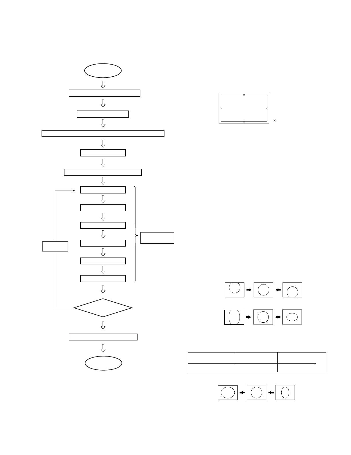
* ADJUSTING FLOW
START
Turn on the power and wait for 10 minutes.
Set to the NTSC Full mode
Check the deflection yokes, the centering magnets, 2 pole/4 pole magnets
Set to the service mode.
MAIN DEFLECTION ADJUSTMENT (Green)
(Item 3-10-2)
Green coarse adjustment
Green fine adjustment
3-11-1. Setup for Adjustment
1. Marking
1) At the 4 insides of the screen, locate the middle. Use a tape
measure to identify the middle.
2. Data Setting
: middle
1) Set NTSC Full mode.
2) Enter the Service mode, and select “PJE”.
Note : When you replaced printed circuit boards or devices or
CRTs, and when correction is drastically necessary, press
“
"” + “ENTER” buttons to initialize the data in the
Projector Engine mode.
Press “MUTING” + “ENTER” buttons on the commander
to write the data.
3-11-2. Main Defl ection Adjustment
Note : Before this adjustment, input the data of PJE item No.
78-85, (See page 23).
Red coarse adjustment
Change the
display mode
ALLCOPY
When the NTSC Full mode
adjustment has finished,
copy its data to the next display mode
at the first time only and be sure to
adjust in the order given.
Yes
Red fine adjustment
Blue coarse adjustment
Blue fine adjustment
Another display mode?
Memorize the FLASH FOCUS offset data
End
SUB DEFLECTION
ADJUSTMENT
(Item 3-10-4)
green color is displayed.
2. Enter the monoscope signal and set to NTSC Full mode .
3. Enter the Service mode, and select “2150D-1” .
4. Adjust “0 VPOS” and “1 VSIZ” so that the picture is displayed in the center of screen.
0 VPOS
1 V-Size
1. Place the caps on the red and blue lenses so that only the
No
5. Select “2150D-2” and adjust “2 H-Size” so that the picture
size is within the specifi cation.
SPEC Overscan Spec. = 9%
Input Signal H SIZE V SIZE
Monoscope 15.6 ± 0.2 sq. 11.5 ± 0.2 sq.
2 H-Size
6. Copy the data of NTSC Full mode to the other display mode
and adjust in the other mode as the occasion demands.
– 25 –
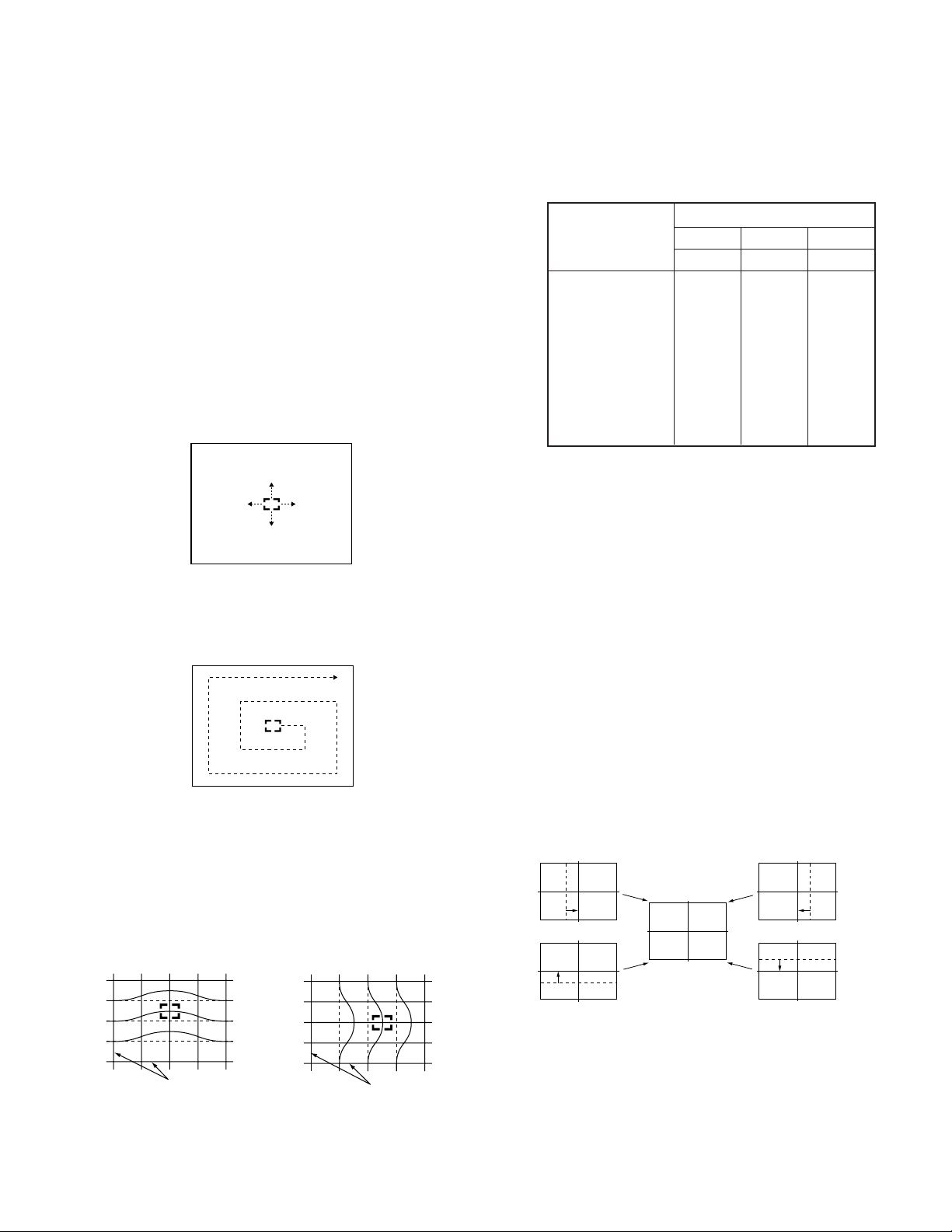
3-11-3. Operation Method for Projector Engine
Mode
MUTING
Category up
Adjustment item
up
Adjustment item
down
Category down
Initialize data
(Not stored)
MENU
data up/down
VOLUME +
TV POWER
DISPLAY
Color change
Internal test signal
Mode select
(Fine or Coarse)
ENTER
KP-43HT20C/53HS30C
RM-Y908RM-Y908
• Press joy :Switches marker moving method.
stick (in fi ne adjustment mode)
joystick (
buttons
Commander Function
Buttons Mode Description
- + ENTER READ Writes data to NVM.
MUTING+ENTER WRITE Reads data from NVM.
7 + ENTER PJE Service data initialization. Not stored.
2. Operation Method for Coarse Adjustment
1) Enter the Service mode, and select “PJE”.
2) Press “
#” or “$” button on the commander to select the
item, and use the joystick to change the data.
!"#$) keys ! # and $
INITIAL
Item No.
(Be sure not to use usually)
Data
RM-Y908
1. Functions of Keys on Commander
• # : Changes adjustment item. (item No. moves up)
: Marker moves clockwise from center to outside.
(in fi ne adjustment mode)
•
$ : Changes adjustment item.
(item No. moves down)
: Marker moves counterclockwise from outside
to center. (in fi ne adjustment mode)
•
& : Changes adjustment category.
(category No. moves up)
•
' : Changes adjustment category.
(category No. moves down)
• Joystick : Changes data value. (up or down)
: Marker moves up, down, or to the left or right.
(in fi ne adjustment mode)
•
% : Changes adjustment color.
GRN ! BLU ! RED
•
( : Displays or changes internal test signals.
: crosshatch + external signal ! crosshatch
+borderline ! crosshatch only ! dot only !
off
•
) : Switches adjustment mode.
Coarse adjustment mode ! fine adjustment
mode
PJE 00 00
FDIS
Joystick
Adjustment Item
!$ direction:Data up
"#direction:Data down
3) Select “GRN CENT” . When BLU or RED is displayed, press
“
%” button on the commander to change the adjustment
color in the order of GRN ! BLU ! RED.
4) In the GRN, BLU, or RED mode,move
the joystick can change the data in vertical direction, or
!"direction
#$direction in horizontal direction.
Color
GRN 000 000
CENT
Data (H)
Data (V)
# :Data (H) up
$ :Data (H) down
Adjustment Item
!:Data (V) up
":Data (V) down
5) Before returning to the Service mode, press “MUTING”
+“ENTER” buttons on the commander to write the data.
(Omission of this operation causes the set data to be returned
to the data before adjustment)
– 26 –
KP-43HT20C/53HS30C
Push the j
Push the j
RM-Y908RM-Y908
3. Operation Method for Fine Adjustment
1) Select the PJE mode.
2) Select FDIS so that the data at each position can be displayed
in the fi ne adjustment mode, and set the data to “01”.
3) Press “
4) Press joystick, and the marker color will be switched between
5) Use “
Operating the joystick can move the marker
)” button on the commander, and the fi ne adjustment
mode will be active where a green marker appears in the
center of screen (in the case of GRN mode).
green (GRN mode) and white alternately.
#” or “$” button on the commander, or the joystick
to move the marker to the position to be adjusted, where fi ne
adjustment can be made.
• When marker color is white.
(in this case, fi ne adjustment is disabled)
up, down, or to the left or right freely.
• When marker color is green. (GRN mode)
# : moves the marker clockwise from center to outside.
$ : moves the marker counterclockwise from outside to
center.
• Fine adjustment can be made on the basis of marker
3-11-4. PJE Adjustment
(Sub Defl ection Adjustment)
Adjustment a : Yes – : No
Adjustment Type
Adjustment Item GRN RED BLU
H / V H / V H / V
CENT a / aa / aa / a
SKEW a / aa / aa / a
SIZE a / aa / aa / a
LIN a / aa / aa / a
KEY – / a – / a – / a
PIN a / aa / aa / a
MLIN a / – a / – a / –
MSIZ a / – a / – a / –
Note: If the value of over the limit value, adjust these in the fi ne
adjustment .
Coarse Data Limit Valune.
Cent H 35±170 V 20±170, Size H-75max, Lin H Blu
-425min, H Red 425max.
<Adjustment for NTSC Full Mode>
• The adjustment should be done in the numerical order
given.
1. Green Adjustment
1) Place the caps on the red and blue lenses so that only the
green color is displayed.
2) Enter the monoscope signal to set.
3) Select the PJE mode.
4) Press “
5) Select “GRN CENT”, and adjust so that the picture coincide
• GRN CENT (horizontally/vertically)
(” button on the commander to display internal test
signal (crosshatch).
in the center of screen.
oystick
to
to
oystick
position using
Move joystick
6) Press “
adjustment mode.
!"#$ directiom of the joystick.
direction
CROSSHATCH
Move joystickdirection
CROSSHATCH
)” button on the commander to return to the coarse
– 27 –
Push the joystick
to
Push the joystick
to
KP-43HT20C/53HS30C
Push the j
Push the j
Push the j
Push the j
Push the j
Push the j
Push the j
Push the j
RM-Y908RM-Y908
7) Select “GRN SKEW”, and correct the tilt of horizontal lines
and vertical lines.
• GRN SKEW (horizontally/vertically)
oystick
to
Push the joystick
to
to
Push the joystick
to
oystick
8) Select “GRN SIZE”, and adjust so that each distance from
center to left end and to right end is equal. Adjust so that each
distance from center to top and to bottom is equal.
• GRN SIZE (horizontally/vertically)
to
oystick
to
oystick
10) Select “GRN MSIZ”, and correct the space intervals for the
horizontal section of the screen are equal.
• GRN MSIZ (horizontally)
Push the joystick
to
Push the joystick
to
11) Select “GRN MLIN”, and correct the sizes of the horizontal
line at the center of the screen are symmetrical left and
• GRN MLIN (horizontally)
Push the joystick
to
Push the joystick
to
Note: The SIZE and LIN, MSIZ and MLIN adjustments are
affected each other.
So adjust these mutually if necessary.
12) Select “GRN PIN”, and adjust so that right and left vertical
lines on the screen become straight. Adjust so that upper and
lower horizontal lines on the screen become straight.
Push the joystick
to
Push the joystick
to
9) Select “GRN LIN”, and adjust so that each space at the right
end and at the left end of screen is equal. Adjust so that each
space at the top and at the bottom of screen is equal.
• GRN LIN (horizontally/vertically)
oystick
to
to
oystick
• GRN PIN (horizontally/vertically)
to
Push the joystick
to
oystick
oystick
to
Push the joystick
to
13)Select “GRN KEY”, and adjust so that upper and lower
horizontal lines on the screen become parallel.
• GRN KEY (vertically)
Push the joystick
to
Push the joystick
to
Push the joystick
to
Push the joystick
to
Note: The VPINand KEY adjustments are affected each other.
So adjust these mutually if necessary.
– 28 –
KP-43HT20C/53HS30C
RM-Y908RM-Y908
14) Press “
15) Make fi ne adjustment so that horizontal lines and vertical
16) Press “
) ” button on the commander to enter the fine
adjustment mode.
lines become straight.
)” button on the commander to return to the coarse
adjustment mode.
2. Red Adjustment
1) Place a cap on the blue lens so that green and red colors
are displayed.
2) Press “
3) Adjust the following items so that red lines overlap with
• RED CENT (horizontally/vertically)
• RED SKEW (horizontally/vertically)
• RED SIZE (horizontally/vertically)
• RED LIN (horizontally/vertically)
• RED MSIZ (horizontally)
• RED MLIN (horizontally)
• RED PIN (horizontally/vertically)
• RED KEY (vertically)
%” button on the commander to select RED mode.
green lines.
<Copy All Registration Data to Other modes>
1. Make sure that the adjustment for NTSC Full mode fi nished
and the data have already been written.
2. Select the PJE mode.
3. Select ALCP and set the data to “01”, and press
“MUTING”+“ENTER” buttons on the commander.
4. The data of NTSC Full mode are copied to all other modes.
Full
Screem
mode
Zoom
Screen
mode
5. Check in the other mode and adjust as the occasion demands.
Be sure to write data in each mode.
Wide Zoom
Screen
mode
Copy Registration Data.
HD
(1080i Full
Screen mode)
3-12. AUTO CONVERGENCE OFFSET
This adjustment must be performed after the registration adjustment
was made or after readjustment was made by any reason.
4) Press “
5) Make fi ne adjustment so that horizontal lines and vertical
6) Press “
) ” button on the commander to enter the fine
adjustment mode.
lines overlap with green lines.
)” button on the commander to return to the coarse
adjustment mode.
3. Blue Adjustment
1) All colors are displayed.
2) Press “
3) Hereinafter, use same manner as that of red adjustment to
%” button on the commander to select BLU mode.
adjust so that the blue lines overlap with green and red lines.
4. Registration Data Writing
1) After each adjustment of green, blue, and red for the NTSC
Full mode fi nished, press “MUTING”+ “ENTER” buttons on
the commander to write registration data to the NVM.
1. Darken the periphery of this set.
2. Enter the monoscope signal to set the NTSC Full mode.
3. Select the PJE mode.
4. Press “FLASH FOCUS” button on the front panel of the set.
(The offset value is now automatically stored)
5. Select “ ERR” of PJE mode.
Confirm ERR is “00”. If ERR is not “00”, recheck. (Refer
to 3-12.)
6. Exit the service mode.
3-13. AUTO REGISTRATION ERROR CODE LIST
If an error code is displayed after the set has been fully adjusted,
correctly, plese check the following items : position, tilt and sizing. If
either of these adjustments are off, even slightli, the auto registration
pattern will not hit the four sensors properly. This occurs when the
internal generator patterns is being fl ashed on the screen for the sensor
to read. Therefore, auto registration (called auto convergence) cannot
operate properly causing an error code to be displayed. In order for
this function to operate properly, correct position, tilt and size must
be adjusted properly.
– 29 –
ERROR CODE LIST
KP-43HT20C/53HS30C
RM-Y908RM-Y908
ERROR
CODE
DESCRIPTION REMEDY
00 No Error
10 Sensor 0 low output Check sensor 0, connection/wiring, circuit, and pattern position
(Is pattern over sensor ?) Adjust “64 VUP” if necessary.
11 Sensor 1 low output Check sensor 1, connection/wiring, circuit, and pattern position
(Is pattern over sensor ?) Adjust “69 HLB” if necessary.
12 Sensor 2 low output Check sensor 2, connection/wiring, circuit, and pattern position
(Is pattern over sensor ?) Adjust “73 HRIV” if necessary.
13 Sensor 3 low output Check sensor 3, connection/wiring, circuit, and pattern position
(Is pattern over sensor ?) Adjust “68 VLOW” if necessary.
20 Sensor 0 high output Check sensor 0 and circuit.
21 Sensor 1 high output Check sensor 1 and circuit.
22 Sensor 2 high output Check sensor 2 and circuit.
23 Sensor 3 high output Check sensor 3 and circuit.
30 V CENT or SKEW adjustment Check “66 VMID” data and check registration condition.
loop overflow
31 H CENT or SKEW adjustment Check “71 HMID” data and check registration condition.
loop overflow
32 H LIN or SIZE adjustment Check “71 HMID” data and check registration condition.
loop overflow
40 V CENT regi data overflow Check “66 VMID” data and confirm V CENT data (all mode) is not near 511.
41 H CENT regi data overflow Check “71 HMID” data and confirm H CENT data (all mode) is not near 511.
42 V SKEW regi data overflow Check “66 VMID” data and confirm V SKEW data (all mode) is not near 511.
43 H SKEW regi data overflow Check “71 HMID” data and confirm H SKEW data (all mode) is not near 511.
44 H LIN regi data overflow Check “71 HMID” data and confirm H CENT data (all mode) is not near 511.
45 H SIZE regi data overflow Check “71 HMID” data and confirm H CENT data (all mode) is not near 511.
50 V CENT regi data overdrow Check “66 VMID” data and confirm V CENT data (all mode) is not near –512.
51 H CENT regi data overdrow Check “71 HMID” data and confirm H CENT data (all mode) is not near –512.
52 V SKEW regi data overdrow Check “66 VMID” data and confirm V SKEW data (all mode) is not near –512.
53 H SKEW regi data overdrow Check “71 HMID” data and confirm H SKEW data (all mode) is not near –512.
54 H LIN regi data overdrow Check “71 HMID” data and confirm H CENT data (all mode) is not near –512.
55 H SIZE regi data overdrow Check “71 HMID” data and confirm H CENT data (all mode) is not near –512.
60 H or V CENT offset overflow Check “71 HMID” data and check “66 VMID” data.
61 H or V SKEW offset overflow Check SKEW adjustment.
62 H SIZE or LIN offset overflow Check “71 HMID” data, check “66 VMID” data and check SIZE and LIN adjustment.
70 H or V CENT offset overdrow Check “71 HMID” data and check “66 VMID” data.
71 H or V SKEW offset overdrow Check SKEW adjustment.
72 H SIZE or LIN offset overdrow Check “69 HLB” data, check “73 HRIV” data and check SIZE and LIN adjustment.
80 SIZE limit error Check that H SIZE is negative and not near zero.
[SENSOR POSITION]
0
12
SCREEN
3
0 : UPPER SENSOR
1 : LEFT SENSOR
2 : RIGHT SENSOR
3 : LOWER SENSOR
Error codes in normal (customer) mode are not displayed.
You must enter PJED service mode to see to the error code.
AUTO REGI ERROR CODE FORMAT
ERROR EXAMPLE
PJE 62 213
ERR
Color:
0=Green
1=Red
2=Blue
Example: Blue low Level Sensor 3
Error Code:
(See Error List)
0-Green
1-Red
2-Blue
– 30 –
When executing fl ash focus in service
mode, the error will be displayed in
text format (see below).
SENSOR POSITIONS
0
ERROR G
LO LEVEL S3
1 2
3
 Loading...