

Sony KLV-L32MRX1, KLV-L42MRX1 Schematic
MRX1
RM-Y1012
SERVICE MANUAL
MODEL
KLV-L32MRX1
COMMANDER DEST
RM-Y1012 AEP
MRX1
MODEL
KLV-L42MRX1
COMMANDER DEST
CHASSIS
RM-Y1012 AEP
LDM-3210/LDM-4210
MBT-MRX1
RM-Y1012
- 1 -
FLAT PANEL COLOR TV

MRX1
RM-Y1012
TABLE OF CONTENTS
Section Title Page Section Title Page
Caution ................................................................ 3
Specifications ...................................................... 4
Connectors .......................................................... 5
Self Diagnosis ..................................................... 6
1. GENERAL ................................................................... 7
2. DISASSEMBLY
2-1. Display Unit-1 (LDM-3210) .............................. 21
2-1-1. Stand Assy and Rear Panel Removal .............. 21
2-1-2. DES and K Boards Removal ........................... 21
2-1-3. G1 Board Removal .......................................... 22
2-1-4. R1 and R2 Boards Removal ............................ 22
2-1-5. LCD Panel Removal ........................................ 23
2-2. Display Unit-2 (LDM-4210) .............................. 24
2-2-1. Rear Cover Removal ....................................... 24
2-2-2. K1 and K2 Boards Removal ........................... 24
2-2-3. DES Board Removal ....................................... 25
2-2-4. G2 Board Removal .......................................... 25
2-2-5. R3 and R4 Boards Removal ............................ 26
2-2-6. Display Panel Removal ................................... 26
2-3. Media Receiver Unit (MBT-MRX1) .................. 27
2-3-1. Top Cover Removal ......................................... 27
2-3-2. U2 Board Removal .......................................... 27
2-3-3. Baseplate and HMP Board Removal ............... 28
2-3-4. H5, H6 and H7 Board Removal ...................... 28
2-3-5. G Board Removal ............................................ 29
2-3-6. A1 Board Removal .......................................... 30
2-3-7. Service Position ............................................... 31
2-3-8. Service Connector for DIC Board ................... 31
2-3-9. LVDS Service Cable ....................................... 31
2-4. Cable Arrangements for Media Receiver
Unit (MBT-MRX1) ............................................ 32
2-4-1. Front Panel Dressing ....................................... 32
2-4-2. A1 Board Dressing .......................................... 32
2-4-3. A1 and G Board Dressing ............................... 32
2-4-4. LVDS and Copper Tape Dressing ................. 32
3. ADJUSTMENTS
3-1. White Balance Adjustment ................................. 33
4. DIAGRAMS
4-1. Block Diagrams .................................................. 34
4-1-1. Display Unit (LDM-3210/4210) ..................... 34
4-1-2. Media Receiver Unit (MBT-MRX1) .............. 38
4-2. Circuit Board Location ........................................ 43
4-2-1. Display Unit (LDM-3210) .............................. 43
4-2-2. Display Unit (LDM-4210) .............................. 43
4-2-3. Media Receiver Unit (MBT-MRX1) .............. 43
4-3. Schematic Diagrams and Printed Wiring
Boards ................................................................. 43
4-3-1. Display Unit (LDM-3210/4210) ..................... 44
4-3-2. Media Receiver Unit (MBT-MRX1) .............. 64
A1 Board Schematic Diagram ............................ 64
A1 Printed Wiring Board .................................. 76
G Board Schematic Diagram .............................. 78
G Printed Wiring Board .................................... 79
H5 Board Schematic Diagram ............................ 80
H5 Printed Wiring Board .................................. 81
IF Board Schematic Diagram .............................. 82
IF Printed Wiring Board ................................... 83
U2 Schematic Diagram ....................................... 84
U2 Printed Wiring Board .................................. 83
4-4. Semiconductors .................................................. 85
5. EXPLODED VIEWS
5-1. Display Unit (LDM-3210) ............................... 88
5-1-1. Display Unit-1 ................................................. 88
5-1-2. Display Unit-2 ................................................. 89
5-2. Display Unit (LDM-4210) ............................... 90
5-2-1. Display Unit-1 ................................................. 90
5-2-2. Display Unit-2 ................................................. 91
5-2-3. Display Unit-3 ................................................. 92
5-3. Packing Materials for Display
Unit (LDM-3210) ............................................. 93
5-4. Packing Materials for Display
Unit (LDM-4210) ............................................. 94
5-5. Media Receiver Unit-1 (MBT-MRX1) .............. 95
5-6. Media Receiver Unit-2 (MBT-MRX1) .............. 96
5-7. Media Receiver Unit-3 (MBT-MRX1) ............ 97
5-8. Packing Materials for Media Receiver
Unit (MBT-MRX1) ............................................ 98
WARNING !!
AN ISOLATION TRANSFORMER SHOULD BE USED DURING
ANY SERVICE WORK TO AVOID POSSIBLE SHOCK HAZARD
DUE TO LIVE CHASSIS, THE CHASSIS OF THIS RECEIVER IS
DIRECTLY CONNECTED TO THE POWER LINE.
6. ELECTRICAL PARTS LIST
6-1. Display Unit (LDM-3210/4010) ...................... 99
6-2. Media Receiver Unit (MBT-MRX1) .................. 124
SAFETY-RELATED COMPONENT WARNING !!
COMPONENTS IDENTIFIED BY SHADING AND MARKED
THE SCHEMATIC DIAGRAMS, EXPLODED VIEWS AND IN THE
PARTS LIST ARE CRITICAL FOR SAFE OPERATION. REPLACE
THESE COMPONENTS WITH SONY PARTS WHOSE PART
NUMBERS APPEAR AS SHOWN IN THIS MANUAL OR IN
SUPPLEMENTS PUBLISHED BY SONY.
- 2 -
ON
CAUTION
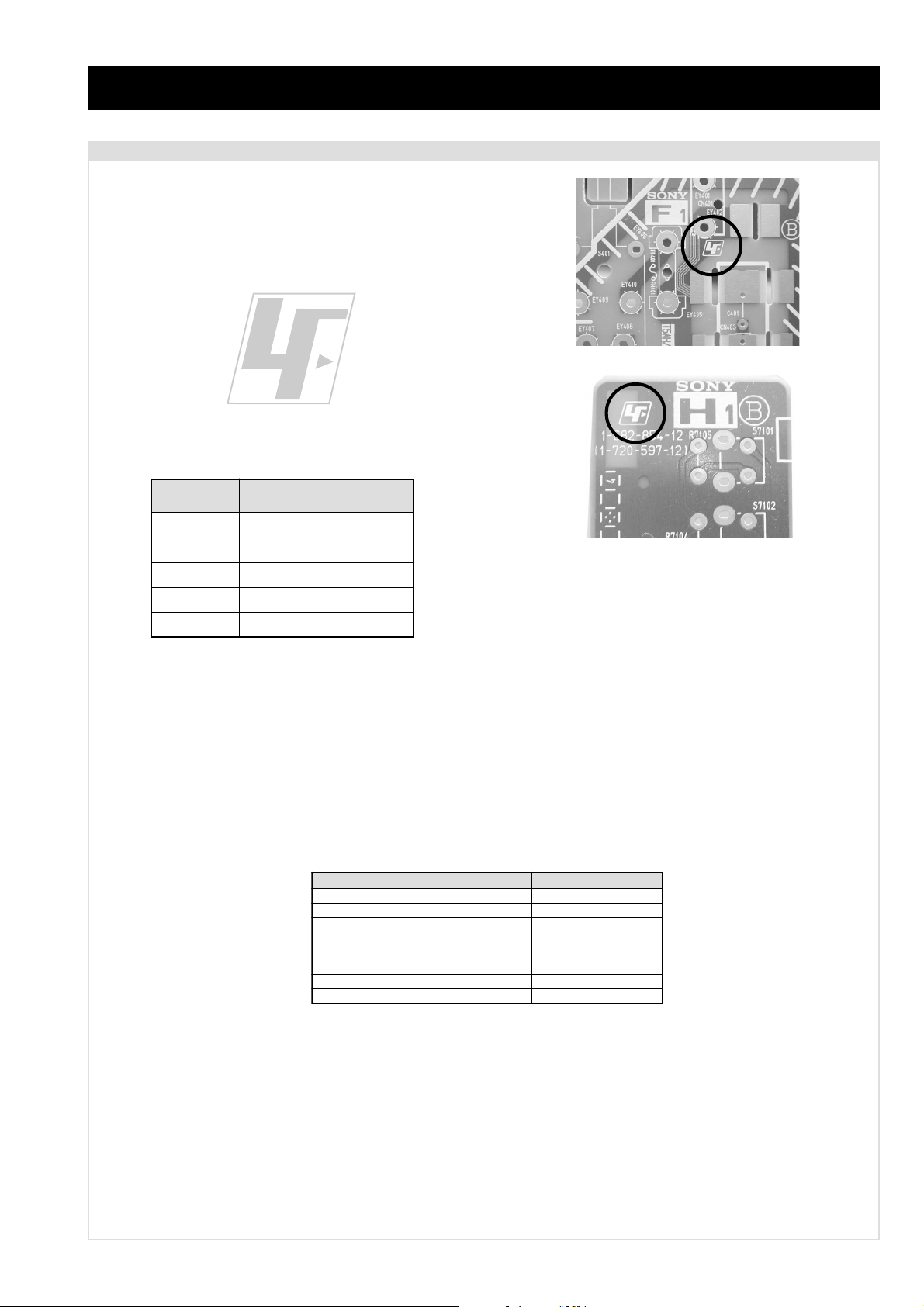
Lead Free Soldered Boards
The circuit boards listed below [Table 1] used in these models
may have been processed using Lead Free Solder. The boards are
identified by the LF logo located close to the board designation
e.g. F1, H1 etc [ see examples ]. The servicing of these boards
requires special precautions to be taken as outlined below.
Table 1
MRX1
RM-Y1012
example 1
example 2
draoB noitcnuF
1AdnEtnorFoiduA&oediV
GylppuSrewoP
5HDELdnayeKtnorF
FI2CIDotecafretnI
2UtuptuO&tupnIlanimreT
It is strongly recommended to use Lead Free Solder material in order to guarantee optimal quality of new solder joints. Lead Free Solder is
available under the following part numbers :
rebmuntraP retemaiD skrameR
91-500-046-7mm3.0gK52.0
02-500-046-7mm4.0gK05.0
12-500-046-7mm5.0gK05.0
22-500-046-7mm6.0gK52.0
32-500-046-7mm8.0gK00.1
42-500-046-7mm0.1gK00.1
52-500-046-7mm2.1gK00.1
62-500-046-7mm6.1gK00.1
Due to the higher melting point of Lead Free Solder the soldering iron tip temperature needs to be set to 370 degrees centigrade. This
requires soldering equipment capable of accurate temperature control coupled with a good heat recovery characteristics.
For more information on the use of Lead Free Solder, please refer to http://www.sony-training.com
- 3 -
LEDOMMETI metsySnoisiveleT metsySoeretS egarevoClennahC metsySroloC
21-20E:FHV
96-12E:FHU
PEAL,I,K/D,H/G/B
MACIN/NAMREG
oeretS
02S-1S:VTELBAC
14S-12S:REPYH
96-12R,21-1R:K/D
96F-12F,Q-B,01-20F:L
96B-12BFHU:I
MRX1
RM-Y1012
MACES,LAP
34.4CSTN,85.3CSTN
)NIOEDIV(
eziSerutciPdetcejorP
rotcennocoruEnip-12:1
)dradnatsCELENEC(
rotcennocoruEnip-12:2
)dradnatsCELENEC(
rotcennocoruEnip-12:3
)dradnatsCELENEC(
skcaJonohP
kcajiniM.CProftupnI
tekcoSAICMCP.eludoMsseccAlanoitidnoC
kcajenohpdaeHkcajinimoerets
stupnioiduAskcajonohp
stupnioediVskcajonohp
tupnioediVSNIDnip4
)lenaPyalpsiDlatsyrCdiuqiL(DCL
-MDL()sehcni23(mc18xorppA
.)0123
-MDL()sehcni24(mc701xorppA
.)0124
]RAER[slanimreTtuptuO/tupnI snoitacificepSlareneG
.slangisoediVdnaoiduArofstupnI
.BGRrofstupnI
oiduAdnaoediVVTfostuptuO
.slangis
.slangisoediVdnaoiduArofstupnI
.BGRrofstupnI
oiduAdnaoediVrotinoMfostuptuO
.slangis
.slangisoediVdnaoiduArofstupnI
.oediVSrofstupnI
slangisoiduAdnaoediVrofstuptuO
.ecafretnikniltramS.)elbatceles(
oiduArofelbairavsrotcennoCtuptuO
.slangiS
]TNORF[slanimreTtuptuO/tupnI lortnocderarfnI:metsyslortnocetomeR
tuptuOdnuoS
rekaepstfeLdnathgiR
stnemeriuqeRrewoPV042-022
/noitpmusnoCrewoP
ybdnatS
snoisnemiD
thgieW
seirosseccAdeilppuS
)1(elbaClaixaoC
serutaeFrehtO
cdV3
stnemeriuqerrewoP
)AAezis(30R
.ecitontuohtiwegnahcottcejbuserasnoitacificepsdnangiseD
)0123-MDL()SMR(W01x2
)0124-MDL()SMR(W41x2
)0123-MDL(W5.0/W051xorppA
)0124-MDL(W5.0/W042xorppA
)1XRM-TBM(W6.0/W24xorppA
)0123-MDL(MM922x536x2501xorppA
)0124-MDL(MM101x496x9431xorppA
)1XRM-TBM(MM343x97x034xorppA
)0123-MDL(gk0.92xorppA
)0124-MDL(gk0.03xorppA
)1XRM-TBM(gk0.6xorppA
)1(rednammoCetomeR2101Y-MR
)2(yrettab30RdetangisedCEI
lautriV,kniltramS,TAP,PAP,CRD,txeteleT
,kcitSyromeM,ICA,EBBlatigiD,ybloD
.noitcetedotuametsysVT
noitangisedCEIseirettab2
metI
emaNledoM
PAPNONO
TAPNONO
ytiroirPBGRNONO
CRDNONO
1tracSNONO
2tracSNONO
3tracSNONO
)5(nitnorFNONO
rotcejorPFFOFFO
G/BmroNNONO
ImroNNONO
K/DmroNNONO
SUAmroNFFOFFO
LmroNNONO
TASmroNFFOFFO
MmroNFFOFFO
txeteleTNONO
oeretSmaciNNONO
1XRM23L-VLK 1XRM24L-VLK
- 4 -
21 pin connector
MRX1
RM-Y1012
21
19
17
15
13
11
9
7
5
3
1
20
18
16
14
12
10
8
6
4
2
Pin No 1 2 4 Signal Signal level
1 Audio output B
2
3
4 Ground (audio)
5 Ground (blue)
6 Audio input A
7 Blue input 0.7 +/- 3dB, 75 ohms positive
8 Function select
9 Ground (green)
10 Open
11 Green Green signal : 0.7 +/- 3dB, 75 ohms,
12 Open
13 Ground (red)
14 Ground (blanking)
15
16 Blanking input
17 Ground (video
18 Ground (video
19 Video output 1V +/- 3dB, 75ohms, positive sync 0.3V
20
21 Common ground
3
(right)
Audio input B
(right)
Audio output A
(left)
(left)
(AV control)
_ _ Red input 0.7 +/- 3dB, 75 ohms, positive
_ (S signal Chroma
input)
(Ys signal)
output)
input)
_ _ Video input 1V +/- 3dB, 75ohms, positive sync 0.3V
_ Video input
Y (S signal)
(plug, shield)
Standard level : 0.5V rms
Output impedence : Less than 1kohm*
Standard level : 0.5V rms
Output impedence : More than 10kohm*
Standard level : 0.5V rms
Output impedence : Less than 1kohm*
Standard level : 0.5V rms
Output impedence : More than 10kohm*
High state (9.5-12V) : Part mode
Low state (0-2V) : TV mode
Input impedence : More than 10K ohms
Input capacitance : Less than 2nF
positive
0.3 +/- 3dB, 75 ohms, positive
High state (1-3V) Low state (0-0.4V)
Input impedence : 75 ohms
(-3+10dB)
(-3+10dB)
1V +/- 3dB, 75ohms, positive sync 0.3V
(-3+10dB)
Connected Not Connected (open) * at 20Hz - 20kHz
Rear Connection Panel Front Connection Panel
niP
oN
1dnuorG-
2dnuorG-
3tupni)langisS(Y,mho57Bd3-/+V1
4tupni)langisS(CBd3-/+V3.0
langiS leveLlangiS
S-Video
socket
noitarugifnocniptekcosoediVS
V3.0.cnySevitisop
Bd01+3-
evitisop,mho57
.cnyS
- 5 -
MRX1
RM-Y1012
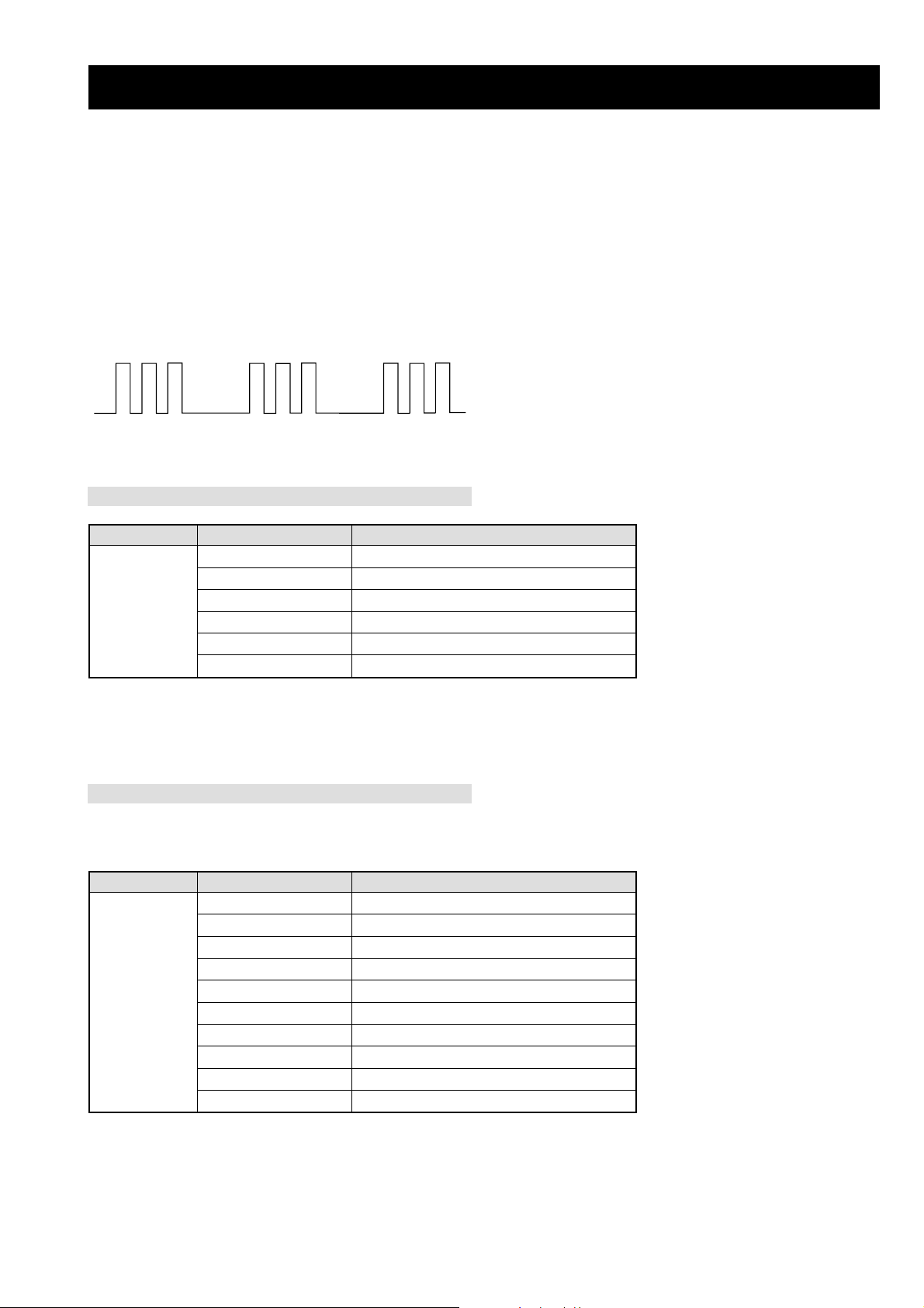
MRX1 SELF DIAGNOSTIC SOFTWARE
The identification of errors within the MRX1 chassis is triggered in one of two ways :- 1: Busy or 2: Device failure to respond to IIC. In the
event of one of these situations arising the software will first try to release the bus if busy (Failure to do so will report with a continuous
flashing LED) and then communicate with each device in turn to establish if a device is faulty. If a device is found to be faulty the relevant
device number will be displayed through the LED (Series of flashes which must be counted).
Flash Timing Example : e.g. error number 3
StBy LED
ON ON
OFF
OFF
Panel
DEL sutatS noitidnoC
gnihsalfdeR/neerGmralAlenaP
sehsalfdeR4rorreerutarepmeT/rorrenaffoegatlovrewoP
DELybtS/rewoP
sehsalfdeR6rorre)draobG(noitcetorprewoP
sehsalfdeR7rorrerekaepsoiduA
gnihsalfegnarOrorrenoitcennocelbaC
)ybtSsaemaS(deRrorrerotrevnocdraobG
MediaBox
Note: All the following are critical errors, so the media box will
automatically go in to Stby.
DEL sutatS noitidnoC
sehsalfdeR2rrorreCII
sehsalfdeR3rorre)5781AXC(rednapxEtroP
sehsalfdeR4rorreMORPEE
sehsalfdeR5rorrenoitacinummoc)7342s8H(orciMbuS
DELybtS/rewoP
sehsalfdeR6rorrekcolCemiTlaeR
sehsalfdeR22rorreerutarepmethgiH
sehsalfdeR32rorrenoitcetorpnaF
sehsalfdeR42rorrenoitcetorprekaepS
sehsalfdeR72rorretsoLnoitatibrAnoitacinumoCCII
sehsalfdeR82rorre)draobN(AMME
- 6 -
The operating instructions mentioned here are partial abstracts
from the Operating Instruction Manual. The page numbers of
the Operating Instruction Manual remain as in the manual.
– 7 –
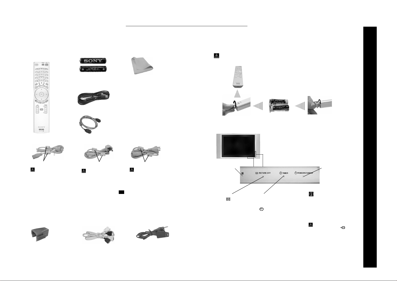
Checking the Accessories supplied
1 Remote control
(RM-Y1012):
2 Mains Leads (Type C-4):
Do not remove ferrite cores.
Use these mains leads (with
safety earth) if you use the
set outside the United
Kingdom and Ireland.
1 Mains Plug holder:
2 Batteries (AA size):
One Coaxial Cable:
1 PC Input Cable
2 Mains Leads (Type BF):
Do not remove ferrite cores.
• Use these mains leads (with
safety earth) if you use the set
in the United Kingdom.
• See “NOTICE FOR
CUSTOMERS IN THE
UNITED KINGDOM and
IRELAND” on page 2
when using these mains leads.
• These mains leads may not be
supplied depending on the
country.
1 Display Interface Cable: 1 AV Mouse:
GB
1 Cleaning cloth:
Only for KE-P61MRX1:
(supplied with the display unit:
PDM-6110)
• 2 Frame Bars
• 4 Screws
Only for KLV-L42MRX1:
(supplied with the display unit:
LDM:4210)
• 2 Speaker jack covers
2 Mains Leads (Type C-5):
Do not remove ferrite cores.
• Use these mains leads (with
safety earth) if you use the set
in the Swiss Confederation.
• These mains leads may not be
supplied depending on the
country.
Inserting Batteries into the Remote Control
Make sure you insert the supplied batteries using the correct polarities.
Always remember to dispose of used batteries in an environmental friendly way.
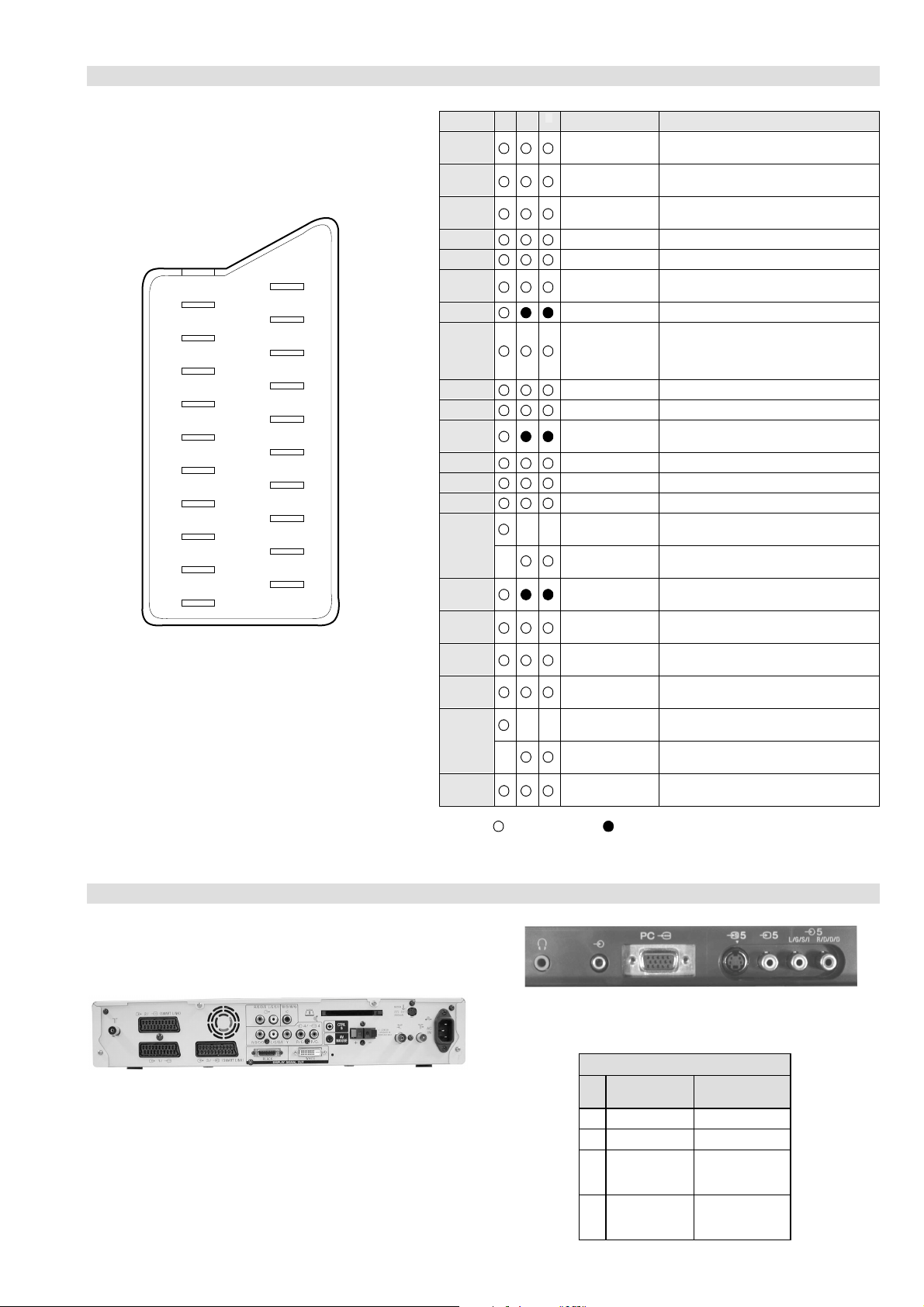
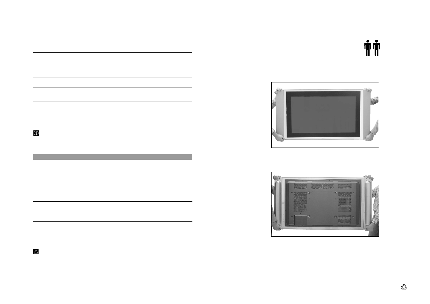
Overview of the Display Unit
or
To operate the
remote control,
point it towards
this receiver.
Lights up in blue when
you press (picture off)
on the remote control to
switch off the picture.
Only the picture is
switched off (the sound
remains unchanged).
Lights up when the
sleep timer is set. For
more details regarding
the sleep timer, refer to
“ Timer” on
page 30.
Lights up in green when the
TV is switched on. When in
standby mode, the indicator
lights up in red. When in PC
power saving* mode, the
indicator lights up in yellow.
*If the TV is connected to a
personal computer or video graphic
board that is DPMS
(Display Power Management
System) compliant, the TV will
automatically reduce power
consumption (PC power saving
mode).
When a personal computer is
connected to the PC socket, the
TV will switch into PC power
saving mode, rather than standby
mode.
SECTION 1 GENERAL
1 “Notes on Plasma” book.
RM-Y1012
MRX1
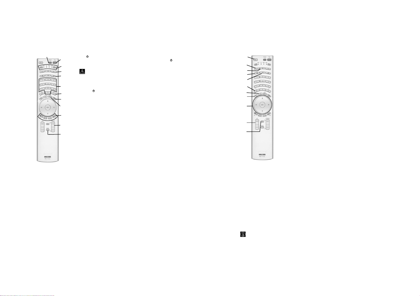
Overview of Remote Control Buttons
2
– 8 –
1 TV I/ : To Temporarily Switch Off TV (standby mode):
1
3
4
5
6
7
8
9
q;
qa
qs
Press this button to temporarily switch off TV (the standby indicator on the TV
lights up). Press again to switch on TV from standby mode.
• To save energy we recommend switching off completely when TV is
not in use.
• If the “Auto Shutoff” option is set to “On” (see page 30) the TV
switches automatically into standby mode after 15 minutes without a
TV signal and without any button being pressed.
2 VIDEO I/ : press this button to switch your VCR or DVD on or off.
3 Media Selector: press these buttons to select which device you want to operate,
TV, VCR, DVD or AUX. A green light will be momentarily lit to show which one
you have selected. For details refer to pages 47-49.
4 Selecting input source: press this button repeatedly until the desired input
symbol of the source appears on the TV screen. Refer to page 52.
5 Selecting the screen format: press this button repeatedly to change the
format of the screen. Refer to page 26.
6 Selecting broadcast channels: if Media Selector (3) is switched to TV,
press these buttons to select channels. For double-digit programme numbers, enter
the second digit within 2.5 seconds.
7 a) Watching last channel selected: if Media Selector (3) is switched to
TV, press this button to return to the previous channel you were watching
(provided you watched it for at least 5 seconds).
b) Selecting VCR double-digit: if Media Selector (3) is switched to VCR,
press this button to select double-digit channels for Sony's VCR e.g. 23, press
-/-- first and next the buttons 2 and 3.
8 Displaying "Memory Stick" menu: for details see pages 38-44.
9 "Memory Stick" Recording button: while the Media Selector is switched
on TV mode, press this button to directly record moving pictures on the
"Memory Stick". To stop the recording process, press this button again.
q; a) Fastext: if Media Selector (3) is switched to TV and whilst you are in
Teletext mode, these buttons can be used as Fastext buttons. For details see
page 45.
b) Operating VCR or DVD: if Media Selector (3) is switched to VCR or
DVD, these buttons will operate the main functions of your VCR or DVD,
once the remote control has been programmed. Refer to page 47.
qa Selecting broadcast channels: press these buttons to select the next or
previous broadcast channel.
qs Menu system: press this button to enter the TV menu system. Refer to page 21.
wd
ws
wa
w;
ql
qk
qj
qh
qg
qf
qd
The buttons labelled qa, qh and qk are also used for Teletext operation. For details see page 45.
.
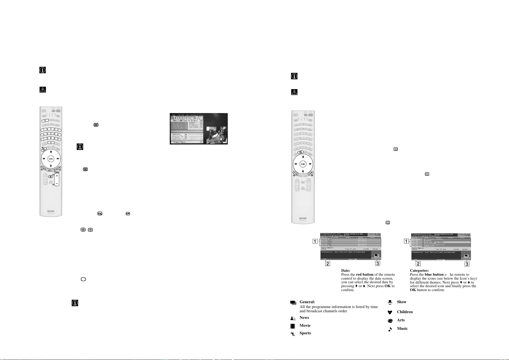
qd Teletext: press this button to switch on Teletext. For details see page 45.
qf Adjusting volume: press these buttons to increase or decrease the volume.
qg a) Displaying a channel or an input signal index: If Media Selector
(3) is switched to TV and MENU is switched off, press OK to display a
channel or input signal index. Once you have pressed OK:
1
To select a channel: press v or V to select a channel and next press
again the OK button to watch the selected channel.
2
To select an input signal: while watching the channel index, press b to
display the input signal (you can always switch from the channel index to
the input signal index and vice versa by pressing
or
V to select an available input signal. Finally press again the OK button
to watch the selected input signal.
b) Navigator: if Media Selector (3) is switched to TV and MENU (qs) is
switched on, use these buttons to navigate through the menu system of the
TV. Refer to page 21.
qh Freezing the picture: press this button to freeze the picture. Press again to
return to the normal picture. If you have inserted a Memory Stick, after
pressing this button you will be requested if you want to store the picture (for
details, see page 44).
qj NexTView: press this button to display NexTView. For details, refer to page
46.
qk Displaying Info: press this button to display all on-screen indication such as
channel number, etc. Press again to cancel.
ql Switching off the picture: press this button to switch off the picture. Only
the picture is switched off; the sound remains on. Press again to cancel.
w; PAP (Picture And Picture): press this button to divide the screen into two
for watching two channels simultaneously. Refer to page 37.
wa Selecting picture mode: press this button repeatedly to change the picture
mode. For details on the different picture modes, refer to page 22.
ws Selecting TV mode: press this button to switch off PAP, Teletext or Video
input mode.
wd Muting the sound: press this button to mute the TV sound. Press again to
restore the sound.
B or b). Next, press v
continued...
RM-Y1012
MRX1
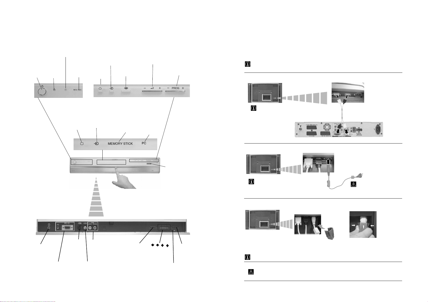
Overview of the Media Receiver
q
On/off
switch
Timer indicator
Power on/
standby
indicator
“Memory
Stick”
recording
indicator
TV indicator
*
Input
indicator (changes
according to the selected
input (see page 52).
Selecting Input
Source button
TV mode
button
"Memory Stick"
access button
“Memory Stick”
lamp
Volume control
button (+/-)
PC indicator
Programme Up
or Down button
(selects TV
channels)
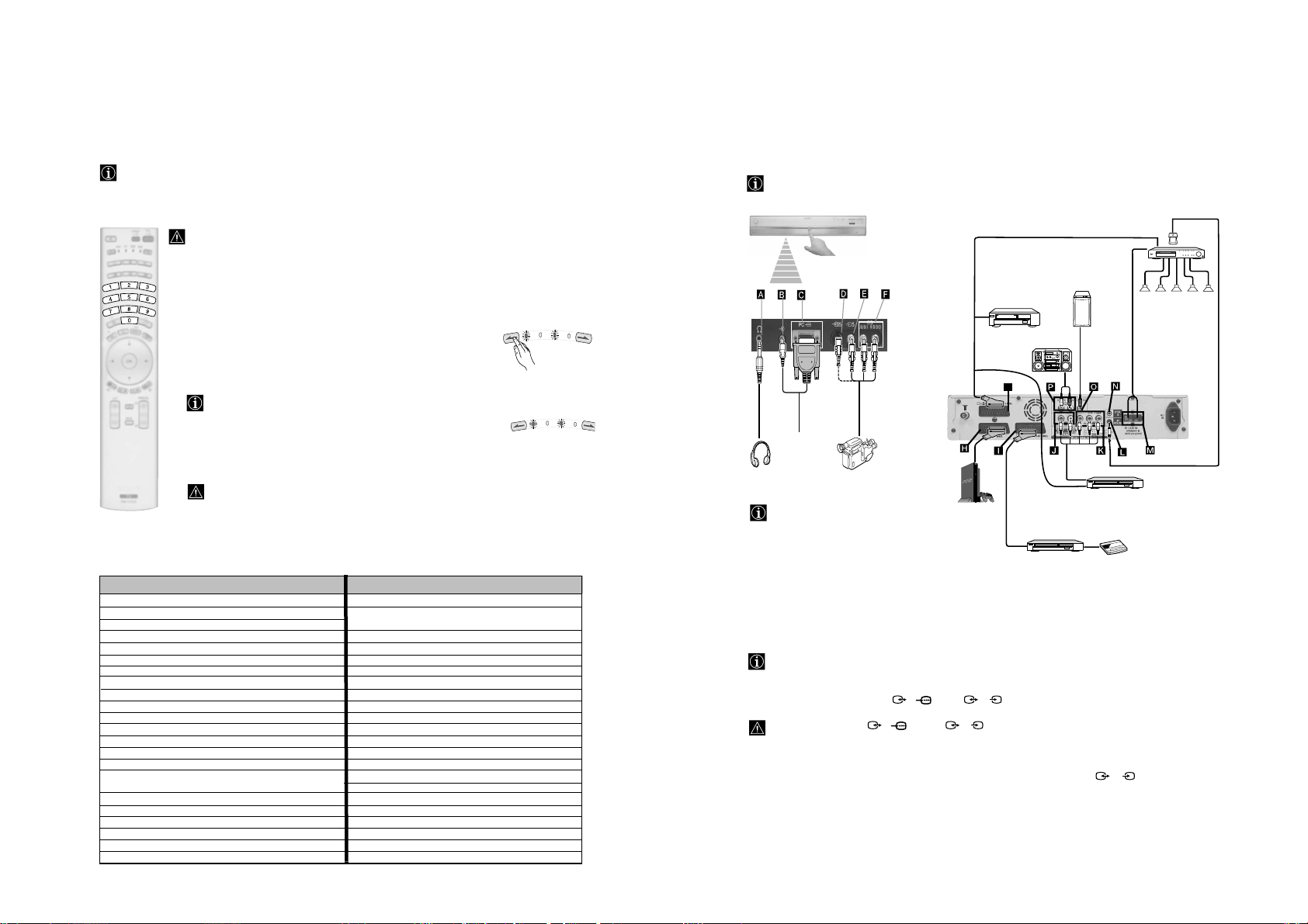
Connecting the Display Unit to the Media Receiver Unit
• Use the supplied display interface cable.
• Use the supplied mains lead for the display unit (Type C-4, Type BF or Type C-5, see page 11).
1 Connect the supplied interface cable to the display unit and to the media receiver unit.
Location of the interface
connections may differ
depending on the model.
*
– 9 –
If the “Logo illuminated”
in the “Features” menu is
set to “Yes” (see page 29),
all these indicators will be
illuminated and each
indicator will be only
underlined according to
your selection. If “Logo
illuminated” is set to
“No”, any of these
indicators will be
illuminated.
Headphones
jack
PC Input C
connectors (video
and audio)
S Video
Input jack
Audio Input
jacks
Video Input
jack
Press on the mark .
Menu button
"Memory Stick"
slot
///
buttons
Auto Start Up button
(starts the auto start up
sequence, see page 19)
OK
button
2 Connect the supplied mains lead to the display unit.
Location of the mains lead
connection may be separated from
the interface connections
depending on the model.
3
Only for KE-P42MRX1, KE-P50MRX1 and KE-P61MRX1:
Attach the mains plug holder
(supplied) to the mains lead.
To unplug the mains lead pull down the mains plug holder by pushing in both sides of the holder, then pull
out the plug.
Do not connect to
the mains before
all connections
are completed.
4 Install the display unit using the specified wall-mount bracket or stand.
Before installing the display unit, check the installation instructions of your wall-mount bracket or stand.
Clip on the AC
IN jack until you
hear clicking.
RM-Y1012
MRX1
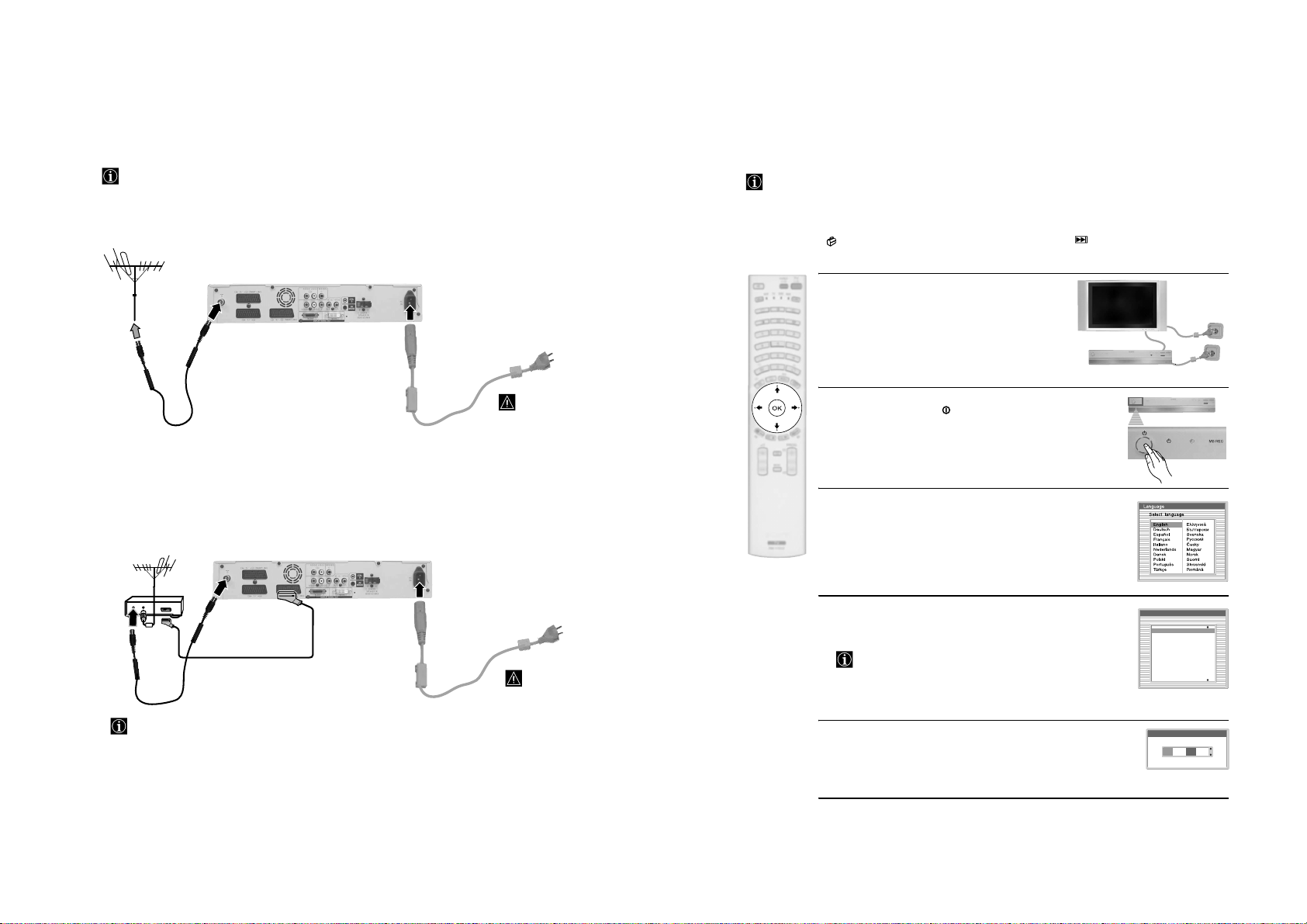
Connecting the Aerial and VCR
t
• Use the supplied mains lead for the media receiver unit (Type C-4, Type BF or Type C-5, see page 11).
• Use the supplied coaxial cable for aerial connection.
Connecting an aerial
Switching On the TV and Automatically Tuning
The first time you switch on your TV, a sequence of menu screens appear on the TV enabling you to: 1) choose
the language of the menu screen 2) Choose the country in which you are going to operate the TV, 3) set the
clock 4) check how to connect optional equipment to your TV, 5) search and store all available channels (TV
Broadcast) and 6) change the order in which the channels (TV Broadcast) appear on the screen.
However, if you need to change any of these settings at a later date, you can do that by selecting the appropriate
option in the (Set Up menu) or by pressing the Auto Start Up button on the media receiver.
1
Connect the display unit and the media receiver unit to
the mains socket (220-240V AC, 50/60Hz).
Do not connect
to the mains
before all
connections
are complete.
2
The first time that the TV set is connected, it is usually turned on.
If the TV is off, press the
the TV.
The first time you switch on the TV, a Language menu appears
automatically on the TV screen.
on/off button on the TV set to turn on
– 10 –
3
Press the V, v, B or b buttons on the remote control to select your
language, then press the OK button to confirm your selection. From
Connecting a VCR with an aerial
VCR
OUT IN
For more details regarding VCR connection, refer to
“Connecting Optional Equipment to the TV” on
page 50.
3/
Do not connec
to the mains
before all
connections
are complete.
now on all the menus will appear in your chosen language.
4
The Country menu appears automatically. Press the v or V button
to select the country in which you are using the TV. Press the OK
button to confirm your selection.
• If the country in which you want to use the TV set does not
appear in the list, select “Off” instead of a country.
• To avoid wrong teletext characters for cyrillic languages we
recommend selecting Russia if your own country does not
appear in the list.
5
The Clock Set menu appears on the TV screen to set the current date
and time.
Press the b button repeatedly to select each item in turn (Day, Month,
Year, Hour and Minutes) and set each item by pressing
press OK to store it.
v or V. Finally
Country
Select country
Off
Ireland
Nederland
België/Belgique
Luxembourg
France
Italia
Schweiz/Suisse/Svizzera
Clock Set
0 0 : 0 0 : 0 0 Mon
RM-Y1012
MRX1
continued...
6
A diagram appears showing you how to connect a wide range of
equipment to your TV set. Follow the instructions and press the
OK button to remove the picture and continue the automatic
process.
The connection diagram should be used as a guide only as
most equipment can be connected to more than one type of
TV socket. Once the TV has completed the automatic
tuning process, refer to the ‘Connection Guide’ section on
page 27 for further information on getting the best set up for
your equipment.
7
The Auto Tuning menu appears on the screen. Press the OK
button to select Yes.
8
The TV starts to automatically search and store all
available broadcast channels for you.
This procedure could take some minutes. Please be patient
and do not press any buttons, otherwise automatic tuning
will not be completed.
In some countries the TV Broadcaster installs the channels
automatically (ACI system). In this case, the TV
Broadcaster sends a menu in which you can select your city
– 11 –
by pressing the
channels.
If no channels were found during the auto tune process, a
message appears automatically on the screen asking you to
connect the aerial. Check the aerial connection (refer to
page 18). Press the OK button to restart the auto tuning
process.
9
After all available channels are captured and stored,
the Programme Sorting menu automatically appears
on the screen enabling you to change the order in
which the channels are stored.
a)
If you wish to keep the broadcast channels in the tuned order,
go to step 10.
b)
If you wish to store the channels in a different order:
1 Press the v or V button to select the programme
number with the channel (TV Broadcast) you wish
to move. Press the
2 Press the v or V button to select the new
programme number position for your selected
channel (TV Broadcast). Press the OK button to store.
3 Repeat steps b)1 and b)2 if you wish to change
the order of the other channels.
v or V button and OK to store the
b button.
Please connect your equipment
according to this chart
DVD
OK
Do you want to start
automatic tuning?
Yes No
Auto Tuning
Programmes found: 4
No channel found.
Please connect aerial
Confirm
Programme Sorting
01
TVE
02
TVE2
03
TV3
04
C33
05
C27
06
C58
07
S02
08
S06
Programme Sorting
TVE
01
TVE2
02
TV3
03
01 TVE
4
C33
0
05
C27
06
C58
07
S02
08
S06
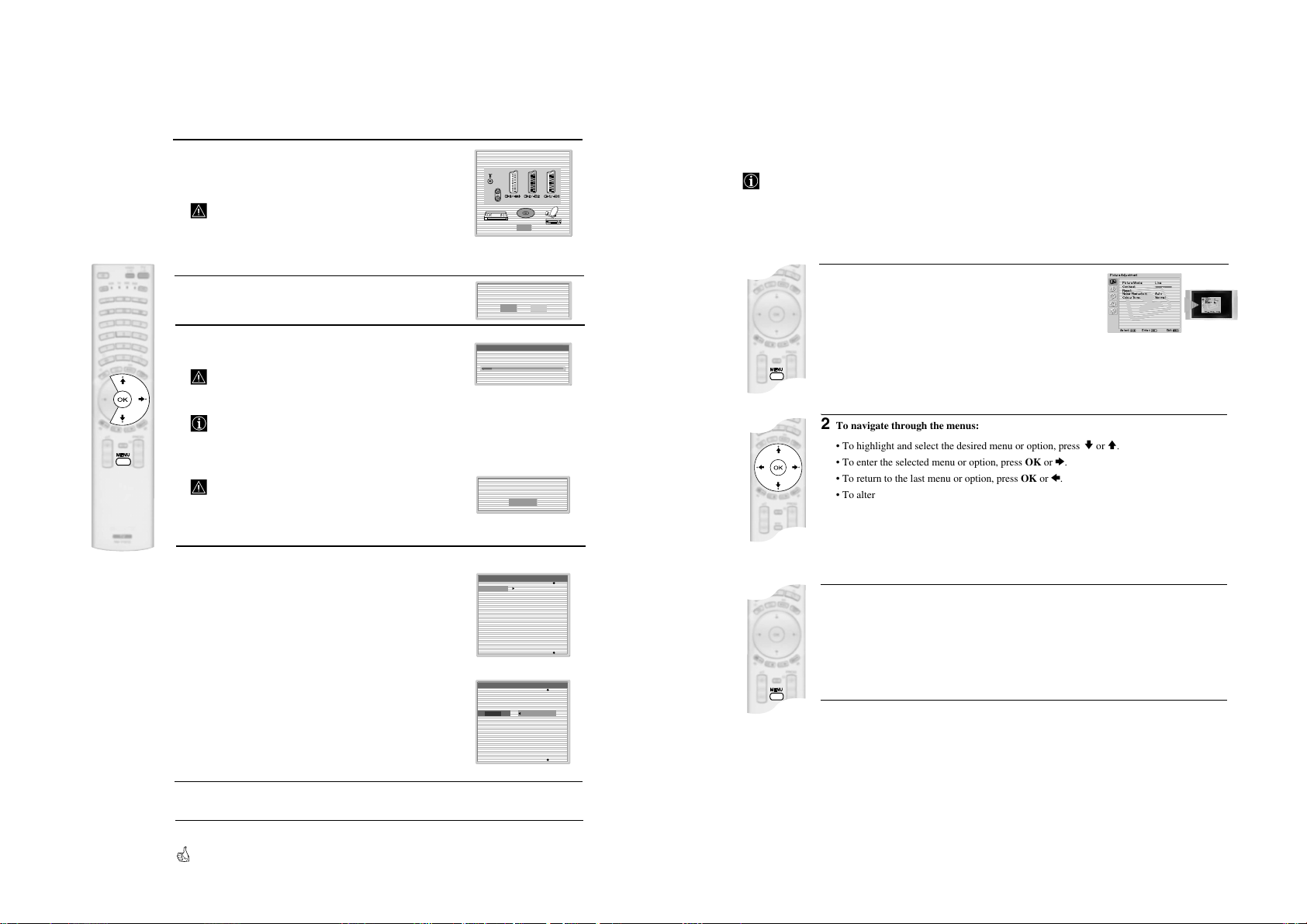
Introducing and Using the Menu System
Your TV set uses an On-Screen menu system to guide you through the operations. Use the following buttons
on the Remote Control to operate the menu system:
v or V.
PictureAdjustment
PictureMode: Live
Contrast:
Reset:
NoiseReduction: Auto
ColourTone: Normal
Select: Enter:OKExit:
1
To switch on the menu screens:
Press the MENU button to switch the first level menu on.
2
To navigate through the menus:
• To highlight and select the desired menu or option, press
• To enter the selected menu or option, press OK or
• To return to the last menu or option, press OK or
• To alter the settings of your selected option, press
• To confirm and store your selection, press OK.
3
To switch off the menu screens:
Press the MENU button to remove the menu from the screen.
b.
B.
v/V/B or b.
PictureAdjustment
PictureMode: Live
Contrast:
Reset:
NoiseReduction: Auto
ColourTone: Normal
MENU
Select: Enter:OKExit:
MENU
10
Press the MENU button to remove the menu from the screen
Your TV set is now ready for use
RM-Y1012
MRX1
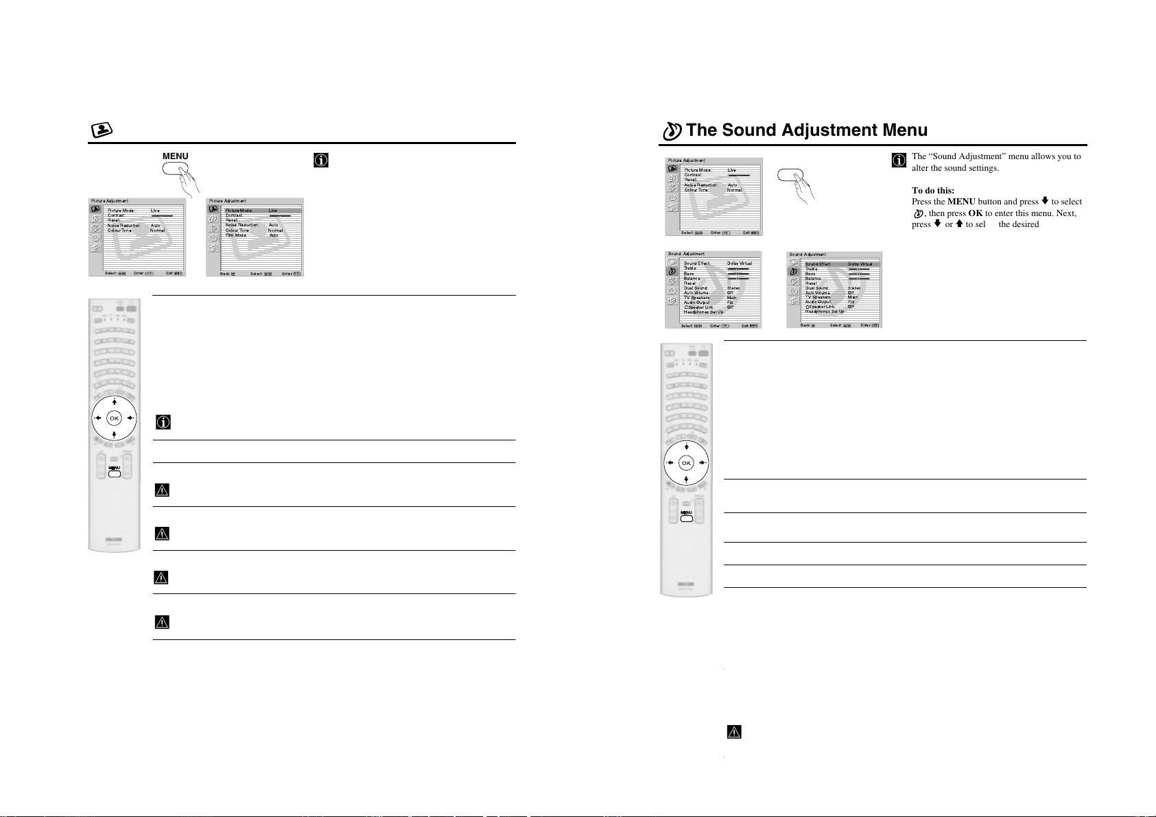
The Picture Adjustment Menu
The Sound Adjustment Menu
MENU
Picture Adjustment
Picture Mode: Live
Contrast:
Reset:
Noise Reduction: Auto
Colour Tone: Normal
Select: Enter:OKExit:
Picture Mode This option allows you to customise the Picture Mode based on the programme
Picture Adjustment
Picture Mode: Live
Contrast:
Reset:
Noise Reduction: Auto
Colour Tone: Normal
,
Film Mode: Auto
MENU
Select:Back:
you are watching. After selecting this option press OK. Next, press repeatedly
V to select:
or
Live (for live broadcast programmes, DVD and Digital Set Top Box
Enter:
receivers).
OK
Movie (for films).
Personal (for individual settings).
– 12 –
"Brightness", "Colour" and "Sharpness" level of "Live" and "Movie" mode are fixed on the
Once you have selected your desired option, press OK to store.
factory to get the best picture quality.
Contrast Press B or b to reduce or enhance picture contrast. Next, press OK to store.
Brightness Press B or b to darken or brighten the picture. Next, press OK to store.
This option only appears and can only be adjusted if “Picture Mode” is set to “Personal”.
Colour Press B or b to decrease or to increase color intensity. Next press OK to store.
This option only appears and can only be adjusted if “Picture Mode” is set to “Personal”.
Hue Press B or b to decrease or to increase the green tones. Next press OK to store.
This option only appears for NTSC signal (e.g. USA video tapes).
Sharpness Press B or b to soften or to sharpen the picture. Next press OK to store.
This option only appears and can only be adjusted if “Picture Mode” is set to “Personal”.
The “Picture Adjustment” menu allows you to
alter the picture settings.
To do this:
Press the MENU button and then press OK to
enter this menu. Next, press
v or V to select the
desired option and press OK. Finally, read below
how to operate into each option.
continued...
Picture Adjustment
Picture Mode: Live
Contrast:
Reset:
Noise Reduction: Auto
Colour Tone: Normal
Select: Enter:OKExit:
Sound Adjustment
v
m
Sound Effect: Dolby Virtual
Treble:
Bass:
Balance:
Reset
Dual Sound: Stereo
AutoVolume: Off
TV Speakers: Main
Audio Output: Fix
Speaker Link: Off
Headphones Set Up
Select: Enter:OKExit:
Sound This option allows you to customise the Sound Effect. After selecting this
Effect option press OK. Next, press repeatedly v or V to select:
MENU
MENU
Sound Adjustment
Sound Effect: DolbyVir tual
Treble:
Bass:
Balance:
Reset
,
Dual Sound: Stereo
AutoVolume: Off
TV Speakers: Main
Audio Output: Fix
Speaker Link: Off
MENU
Headphones Set Up
Dolby* (Dolby Virtual, simulates the sound effect of “Dolby Surround Pro
Virtual Logic”).
Dynamic (“BBE High Definition Sound system”** intensifies clarity and presence
of sound for better intelligibility and musical realism).
Natural (Enhances clarity, detail and presence of sound by using “BBE High
Definition Sound system”**).
Enter:
Select:Back:
Off (Flat response).
Once you have selected your desired option, press OK to store.
Treble Press B or b to decrease or to increase higher-frequency sounds. Next, press OK to
Bass Press B or b to decrease or to increase the lower-frequency sounds. Next, press OK
store.
to store.
Balance Press B or b to emphasise the left or the right speaker. Next, press OK to store.
Reset Press OK to reset the sound to the factory preset levels.
Dual Press b. Next:
Sound • For a Stereo broadcast:
Press
v or V to select Stereo or Mono. Next press OK to store.
• For a bilingual broadcast:
Press
v or V to select Mono (for mono channel if available), A (for channel 1) or B
(for channel 2). Next press OK to store.
Auto Press b. Next press v or V to select On (the volume level of the channels will
Volume stay the same, independent of the broadcast signal, e.g. in the case of advertisements)
or Off (the volume level changes according to the broadcast signal). Next press OK to
store.
If you select “Dolby Virtual” on the “Sound Effect” option, the “Auto Volume” option will
automatically be switched to “Off” and vice versa.
The “Sound Adjustment” menu allows you to
alter the sound settings.
To do this:
Press the MENU button and press
, then press OK to enter this menu. Next,
v or V to select the desired option and
press
press OK. Finally, read below how to operate
into each option.
OK
v to select
RM-Y1012
MRX1
continued...
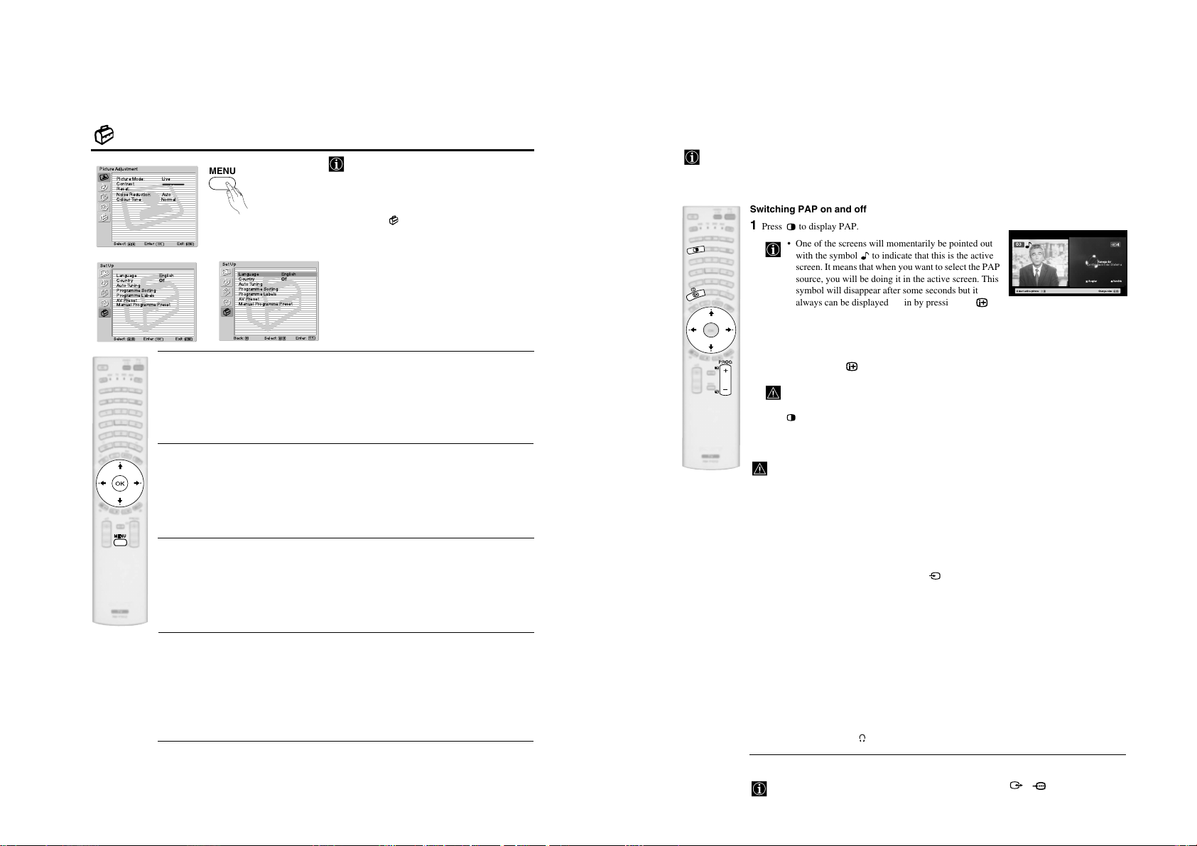
The Set Up Menu
Picture Adjustment
Picture Mode: Live
Contrast:
Reset:
Noise Reduction: Auto
Colour Tone: Normal
Select: Enter:OKExit:
m
Set Up
Language English
Country Off
AutoTuning
Programme Sorting
Programme Labels
AVPreset
Manual Programme Preset
Select: Exit:
Enter:
OK
MENU
MENU
Set Up
Language English
Country Off
AutoTuning
Programme Sorting
Programme Labels
AVPreset
,
Manual Programme Preset
OK
Enter:
MENU
Select:Back:
LANGUAGE
This option allows you to select the language that menus are displayed in.
To do this:
After selecting the option, press OK and then proceed in the same way as in step 3 of the section
– 13 –
"Switching On the TV and Automatically Tuning" on page 19.
The “Set Up” menu allows you to alter various
options on this TV.
To do this:
v
Press the MENU button and press
four times
to select , then press OK to enter this menu.
v
Next, press
or V to select the desired option
and press OK. Finally, read below how to
operate into each option.
PAP (PICTURE AND PICTURE)
PAP divides the screen into two to watch two pictures simultaneously.
Switching PAP on and off
1 Press to display PAP.
• One of the screens will momentarily be pointed out
with the symbol to indicate that this is the active
screen. It means that when you want to select the PAP
source, you will be doing it in the active screen. This
symbol will disappear after some seconds but it
always can be displayed again by pressing the
button.
• On the screen appears a banner guiding you how to
operate PAP. This banner will disappear after some
seconds but it always can be displayed again by
pressing the button.
PAP mode is not available when viewing “Memory Stick” pictures, a PC input signal or
a high definition signal (e.g. 576p signal from a DVD recorder).
2 Press again to remove PAP.
03
Navegador
Configuracióndel Sistema
Selectactive picture: Changesize:
Aceptar Versión
COUNTRY
This option allows you to select the country in which you wish to operate the TV set.
To do this:
After selecting the option, press OK and then proceed in the same way as in step 4 of the section
"Switching On the TV and Automatically Tuning" on page 19.
AUTO TUNING
This option allows you to automatically search for and store all available TV channels.
To do this:
After selecting the option, press OK and then proceed in the same way as in the steps 7 and 8 of
the section “Switching On the TV and Automatically Tuning” on page 20.
PROGRAMME SORTING
This option allows you to change the order in which the channels (TV Broadcast) appear on the
screen.
To do this:
After selecting the option, press OK and then proceed in the same way as in the step 9 of the section
“Switching On the TV and Automatically Tuning” on page 20.
continued...
Changing the active screen
This is only possible if Media Selector is set to TV.
To change the active screen (framed), press the
B or b buttons.
Selecting PAP source
1 Press B or b to select the active screen.
2 Once you have selected the active screen, press the number buttons or PROG +/- if you want to
select a TV channel or press repeatedly the button to watch the input signal of a connected
equipment onto the active screen (for more details on which symbol you want to choose, please
see section “Viewing pictures from equipment connected to the TV” on page 52).
Zooming the screens
With PAP switched on, press v or V to change the size of the two screens.
Selecting the sound
The sound of the active screen always comes from the TV set loudspeakers.
Besides that, you can listen to the active screen as well as the non active screen via headphones.
To do this:
With the PAP switched on, refer to the section "The Sound Adjustment Menu", select "Headphones
Set Up" and set the option " PAP Sound" according your preference. For details see page 25.
In PAP (picture and picture) mode, the output from the Scart 2/ is fixed to the left
picture.
RM-Y1012
MRX1
Teletext
Teletext is an information service transmitted by most TV stations. The index page of the teletext service
(usually page 100) gives you information on how to use the service. To operate teletext, use the remote control
buttons as indicated below.
Teletext errors may occur if you use a channel (TV Broadcast) with a weak signal.
To switch on Teletext :
1 Select the broadcast channel which carries the teletext
service you wish to view.
2 Press the button once to enter Picture And Text
(PAT) mode. The screen is divided into two with the
Text display on the left and the TV channel in the
botton right corner.
While viewing PAT, you can zoom the picture
screen by pressing
two screens are overlapped, they can be swapped
by pressing the OK button.
3 If you wish to view the Text in full screen mode, press
the button a second time.
– 14 –
To select a Teletext page:
Input 3 digits for the page number, using the numbered buttons.
• If you make a mistake, retype the correct page number.
• If the counter on the screen continues searching, it is because the page
is not available. If this is the case, input another page number.
To access the next or preceding page:
Press PROG + ( ) or PROG - ( ) .
To freeze a teletext page:
Press / . Press it again to cancel the freeze.
To select a sub page:
A teletext page may consist of several sub pages. In this case, one or more arrows appear next
to the page number. Press
showing the number of sub pages contained on this page. As soon as sub pages are available, they
start to automatically run. If you want to stop the show and select your desired sub page, press
repeatedly
B or b.
To Switch Off Teletext:
Press .
Fastext
Fastext service lets you access Teletext pages with one button push.
When you are in Teletext mode and Fastext is broadcast, a colour coded menu appears at
the bottom of the teletext page. Press the appropriate coloured button (red, green, yellow
or blue) to access the page corresponding to your menu choice.
v or V buttons. Once the
B or b to display an information line at the bottom of the screen
NexTView*
*(depending on availability of service).
NexTView is an on-screen electronic programme guide, providing you with programme information for
different broadcasters.
When looking for information you can search by theme (sports, art, etc...) or date.
If wrong characters appear when viewing NexTView, use the menu system to enter the “Language” menu (see
page 33) and select the same language as the NexTView is broadcasted.
Displaying NexTView
1 Select a broadcast channel providing a NexTView service. In this case the indication
“NexTView” is displayed as soon as data is available.
2 To see NexTView service you have two different types of NexTView interface. These depend
on the % of available data:
a) “Programme List” interface:
Whilst you are watching TV, and after the indication “NexTView” (coloured orange) is
displayed on the screen, press the button on the remote control to watch the
“Programme List” interface (see fig. 1).
b) “Overview” interface:
Whilst you are watching TV, and after more than 50% of NexTView data is available
(100% data may not be available depending on the area) the indication “NexTView”
(coloured black) is displayed on the screen. Press the button on the remote control
to watch the “Overview” interface (see fig. 2).
3 To navigate through NexTView:
B or b to move left or right.
• Press
•Press
v or V to move downwards or upwards.
• Press OK to confirm a selection.
• If you have selected a programme, press OK to get more information on the
selected programme.
4 To switch NexTView off, press the button on the remote control.
“Programme List” interface (fig. 1): “Overview” interface (fig. 2):
1 Programmme list
Icons’ key:
General:
All the programme information is listed by time
and broadcast channels order.
News
Movie
Sports
Praesentiertvon
IhrerProgrammzeitschr
Thu12
14:30
AttrText
AttrText
AttrText
1
AttrText
AttrText
AttrText
PerryMason
RTL2
Krimiserie- Der Fall mit dem mittelmass
2
2 3
15:30 16:00
AttrText16
AttrText16
AttrText16
AttrText16
AttrText16
AttrText16
Thu12 Jun
General
CategoriesDate
14:36
www.tvmovie.de
15:00
Tue17 Jun 14:55 - 16:30
Select:
3
Date:
Press the red button of the remote
control to display the date screen,
you can select the desired date by
pressing v or V. Next press OK to
confirm.
Praesentiertvon
IhrerProgrammzeitschr
Thu12
AttrText
AttrText
AttrText
1
AttrText
AttrText
AttrText
PerryMason
RTL2
Krimiserie- Der Fall mit dem mittelmass
Date
www.tvmovie.de
15:00
14:30
Aufschlimmer undewig
Baywatch
BennyHill
Perry Mason
TheOsbournes
Segeln:Louis Vuitton Cup
TwilightZone
Tue17 Jun 14:55 - 16:30
Select:
2
Categories:
Press the blue button of the remote to
display the icons (see below the Icon’s key)
for different themes. Next press v or V to
select the desired icon and finally press the
OK button to confirm.
Show
Children
Arts
Music
15:30 16:00
Thu12 Jun
General
categories
14:36
3
RM-Y1012
MRX1
Remote Control Configuration for VCR or DVD
In it’s default condition this remote control will operate the basic functions of this Sony TV, Sony DVDs and
most Sony VCRs. To control VCRs and DVDs of other manufacturers (and some Sony VCR models), the
remote control needs to be configured.
fig. 2
To do this:
• Before you start, look up the 3 digit code for your brand of DVD or VCR from the list below.
On those brands that have more than one code, enter the first code number.
• Sony will endeavour to update the software according to market changes. Therefore, please
refer to the code table included with the remote control for latest code set.
• A small label is provided inside the battery door to allow you to record your brand codes.
1 Press and hold the
seconds until the green DVD and VCR light of the Media Selector starts
flashing (see fig. 1).
>
button on the remote control for approximately 6
VC
fig. 1
DVD
TV
AUX
R
Connecting Equipment to the TV
• Using the following instructions you can connect a wide range of optional equipment to your TV set.
• Connecting cables are not supplied.
Sub woofer
DVD Recorder
Hi-Fi
Compact AV
System /Amplifier
2 While the VCR and DVD lights are flashing, enter all three digits of the
code for your brand of VCR or DVD (see the list below) using the number
buttons on the remote control (see fig. 2).
If your selected code is entered correctly, the green VCR or DVD
light (according to your selection) will be lit momentarily (see fig.
3), otherwise repeat all the above steps.
3 Turn on your VCR or DVD and check that the main functions (playback,
– 15 –
stop, rewind, fast forward and channel selection for both VCR and DVDs
as well as Menu and cursors buttons only for DVDs) work.
• If your device is not working or some of the functions do not work please check that you
entered the correct code or try the next code listed against the brand.
• Not all brands are covered and not all models of every brand may be covered.
4 Always remember to press the
the equipment you want to operate with this remote control: VCR, TV or DVD. Refer to pages
48 -49 on how to operate the AUX mode.
>
or . button until the green light iluminates according to
VCR Brand List DVD Brand List
Brand Code Brand Code
SONY (VHS) 301, 302, 303, 308, 309,362
SONY (BETA) 303, 307, 310
SONY (DV) 304, 305, 306
AIWA 325, 331, 351
AKAI 326, 329, 330
DAEWOO 342, 343
GRUNDIG 358, 355, 360, 361, 320, 351, 366
HITACHI 327, 333, 334
JVC 314, 315, 322, 344, 352, 353, 354, 348, 349
LG 332, 338
LOEWE 358, 355, 360, 361, 320, 351
MATSUI 356, 357
ORION 328
PANASONIC 321, 323
PHILIPS 311, 312, 313, 316, 317, 318, 358, 359,
SAMSUNG 339, 340, 341, 345
SANYO 335, 336
SHARP 324
THOMSON 319, 350, 365
TOSHIBA 337
363, 364
SONY 001, 029, 030, 036, 037, 038, 039, 040,
AIWA 021
AKAI 032
DENON 018, 027, 020, 002
GRUNDIG 009, 028, 023, 024, 016, 003
HITACHI 025, 026, 015, 004, 035
JVC 006, 017
KENWOOD 008
LG 015, 014, 034
LOEWE 009, 028, 023, 024, 016, 003
MATSUI 013, 016
ONKYO 022, 033
PANASONIC 018, 027, 020, 002, 045, 046, 047
PHILIPS 009, 028, 023, 024, 016, 003, 031
PIONEER 004, 050, 051, 052
SAMSUNG 011, 014
SANYO 007
SHARP 019, 027
THOMSON 012
TOSHIBA 003, 048, 049
YAMAHA 018, 027, 020, 002
041, 042, 043, 044, 053, 054, 055
6 sec.
fig. 3
G
DVD
TV
A
U
VCR
X
Personal
computer
S VHS/Hi8/DVC
camcorder
To avoid snowy picture,
do not connect external
equipment to connectors
D and E at the same
time.
*
*
n
o
i
t
2
a
t
layS
P
“PlayStation”*
“PlayStation” is a
product of Sony
Computer
Entertainment, Inc.
“PlayStation” is a
trademark of Sony
Computer
Entertainment, Inc.
VCR
Decoder
DVD Recorder
with component
signal format
Connecting a VCR
To connect a VCR, please refer to the section “Connecting the aerial and VCR” of this instruction manual on page 18.
Connecting a VCR or a DVD recorder that supports SmartLink
SmartLink is a direct link between the TV set and a SmartLink compatible VCR/DVD recorder. For more
information on SmartLink, please refer to the instruction manual of your SmartLink VCR/DVD recorder.
If you use a VCR or a DVD recorder that supports SmartLink, please connect the VCR or the DVD recorder to the
TV using a Scart lead to the Scart 2/ G or 3/ I.
Both Scart connectors 2/ G and 3/ I cannot support SmartLink at the same time. If you
connect a VCR or a DVD recorder to both Scart connectors, select which Scart supports SmartLink through
the “SmartLink” option in the “Features” menu. For details see page 27.
If you have connected a decoder or a Set Top Box to the Scart 3/ I or through a
VCR connected to this Scart
Select the “Manual Programme Preset” option in the “Set Up” menu and after entering in the “Decoder**” option,
select “On” (refer to page 36). Repeat this option for each scrambled signal.
**This option is only available depending on the country you have selected in the “Country” menu.
S
S
S
RM-Y1012
MRX1
continued...

Viewing pictures from equipment connected to the TV
1 Connect your equipment to the designated media receiver socket, as indicated on page 50.
2 Switch on the connected equipment.
3 To watch the picture from the connected equipment, press the button repeatedly until the
correct input symbol appears on the screen.
Symbol Input Signals
1 • Audio / video input signal through the Scart connector H
1 • RGB input signal through the Scart connector H. This symbol appears only if
– 16 –
4 • Component input signal through the Y, P
6 • RGB input signal through the PC connectors B and C.
4 Press the button on the remote control to return to the normal TV picture.
For Mono Equipment
Connect the phono plug to the L/G/S/I socket on the front of the media receiver unit and select
5 or 5 input signal using the instructions above. Next, refer to the “Sound Adjustment”
section of this manual and set “Dual Sound” option to “A” on the sound menu screen (see page
14).
an RGB source has been connected.
2 • Audio / video input signal through the Scart connector G.
2 • RGB input signal through the Scart connector G. This symbol appears only if
an RGB source has been connected.
3 • Audio/video input signal through the Scart connector I.
S
3 • S Video Input signal through the Scart connector I. This symbol appears only
if an S Video source has been connected.
, PR/CR jacks K and audio input
signal through J.
5 • Video input signal through the phono socket E and Audio input signal through
F.
S
5 • S Video Input signal through the front S Video input jack D and Audio signal
through F. This symbol appears only if an S Video source has been connected.
S
B/CB
Technical Specifications
KE-P42MRX1, KE-P50MRX1, KE-P61MRX1,
KLV-L32MRX1 and KLV-L42MRX1:
Media Receiver Unit (MBT-MRX1)
Power Requirement: 220-240V AC; 50/60 Hz
Power Consumption: 42 W
Standby Power Consumption: 0.6 W
Dimensions (w x h x d):
Approx. 430 x 79 x 343 mm
Weight: Approx. 6 kg
KE-P42MRX1 only:
Display Unit (PDM-4210)
Power Requirement: 220-240V AC; 50/60 Hz
Screen Size: 42 inches
Approx. 107 cm measured diagonally
Display Resolution:
1024 dots (horizontal) x 768 lines (vertical)
Power Consumption: 430 W
Standby Power Consumption: 0.6 W
Sound Output: 2 x 15 W (RMS)
Dimensions (w x h x d):
Approx. 1,352 x 720 x 102 mm
Weight: Approx. 39.5 kg
KE-P50MRX1 only:
Display Unit (PDM-5010)
Power Requirement: 220-240V AC; 50/60 Hz
Screen Size: 50 inches
Display Resolution:
Power Consumption: 516 W
Standby Power Consumption: 0.6W
Sound Output: 2 x 15 W (RMS)
Dimensions (w x h x d):
Weight: Approx. 53 kg
KE-P61MRX1 only:
Display Unit (PDM-6110)
Power Requirement: 220-240V AC; 50/60 Hz
Screen Size: 61 inches
Display Resolution:
Power Consumption: 770 W
Standby Power Consumption: 0.6W
Sound Output: 2 x 15 W (RMS)
Dimensions (w x h x d) including speakers:
Dimensions (w x h x d) without speakers:
Weight including speakers:
Weight without speakers:
Approx. 127 cm measured diagonally
1365 dots (horizontal) x 768 lines (vertical)
Approx. 1,573 x 856 x 108 mm
Approx. 155 cm measured diagonally
1365 dots (horizontal) x 768 lines (vertical)
Approx. 1,797 x 937 x 110 mm
Approx. 1,571 x 937 x 100 mm
Approx. 71 kg
Approx. 68 kg
KLV-L32MRX1 only:
Display Unit (LDM-3210)
Power Requirement: 220-240V AC; 50/60 Hz
Screen Size: 32 inches
Display Resolution:
Power Consumption: 150 W
Standby Power Consumption: 0.5 W
Sound Output: 2 x 10 W (RMS)
Dimensions (w x h x d) including the supplied stand:
Dimensions (w x h x d) without the supplied stand:
Weight with the supplied stand: Approx. 29 kg
Weight without the supplied stand: Approx. 22 kg
KLV-L42MRX1 only:
Display Unit (LDM-4210)
Power Requirement: 220-240V AC; 50/60 Hz
Screen Size: 42inches
Display Resolution:
Power Consumption: 240 W
Standby Power Consumption: 0.5 W
Sound Output: 2 x 14 W (RMS)
Dimensions (w x h x d) including speakers:
Dimensions (w x h x d) without speakers:
Weight including speakers: Approx. 30 kg
Weight without speakers: Approx. 25,5 kg
Panel System:
• KE-P42MRX1, KE-P50MRX1 and KE-P61MRX1:
• KLV-L32MRX1 and KLV-L42MRX1:
TV system:
Depending on your country selection:
B/G/H, D/K, L, I
Colour system:
PAL, SECAM
NTSC 3.58, 4.43 (only Video In)
Aerial:
75 ohm external terminal for VHF/UHF
Channel Coverage:
VHF: E2-E12
UHF: E21-E69
CATV: S1-S20
HYPER: S21-S41
D/K: R1-R12, R21-R69
L: F2-F10, B-Q, F21-F69
I: UHF B21-B69
Approx. 81 cm measured diagonally
1280 dots (horizontal) x 768 lines (vertical)
Approx. 1,052 x 635 x 229 mm
Approx. 1,052 x 569 x 97 mm
Approx. 107 cm measured diagonally
1366 dots (horizontal) x 768 lines (vertical)
Approx. 1,349 x 694 x 101 mm
Approx. 1,156 x 694 x 101 mm
PDP (Plasma Display Panel)
LCD (Liquid Crystal Display panel).
continued...
RM-Y1012
MRX1
Rear Terminals:
• AV1: 1/
21-pin Scart connector (CENELEC standard)
including audio/video input, RGB input, TV audio/
video output.
• AV2: 2/ (SMARTLINK; selectable)
21-pin Scart connector (CENELEC standard)
including audio/video input, RGB input, selectable
audio/video output and SmartLink interface.
• AV3: 3/ (SMARTLINK; selectable)
21-pin Scart connector (CENELEC standard)
including audio/video input, S video input,
selectable audio/video output and Smartlink
interface.
• AV4:
• 4: Y:1 Vp-p, 75 ohms, 0.3V negative sync
• 4: audio input (phono jacks)
• Sub Woofer output (phono jack)
– 17 –
• audio outputs (Left/Right) - phono jacks
• CENTRE SPEAKER IN: Max. 180W (6-ohms)
• CTRL S: minijack
• AV MOUSE: minijack
Front Terminals:
• AV5:
• 5: S video input (4-pin mini DIN):
negative
• 5: video input (phono jack):
negative
• 5: audio input (phono jacks):
• AV6:
• PC
• PC :
• headphones jack
• Memory Stick Slot
S
PB:0.7 Vp-p, 75 ohms
PR:0.7 Vp-p, 75 ohms
500 m Vrms (100% modulation),
Impedance: 47 kilo ohms
S
Y: 1 Vp-p, 75-ohms unbalanced, sync
C: 0.286 Vp-p (Burst signal), 75 ohms
1 Vp-p, 75-ohms unbalanced, sync
500 m Vrms (100% modulation),
Impedance: 47 kilo ohms
PC Input (15-Dsub)
G:0.7 Vp-p, 75 ohms, non Sync on Green
B:0.7 Vp-p, 75 ohms, non Sync on Green
R:0.7 Vp-p, 75 ohms, non Sync on Green
HD:1-5 Vp-p
VD:1-5 Vp-p
PC audio input: minijack
Accessories supplied:
• One Remote Control (RM-Y1012)
• Two size AA batteries (R03 type)
• One Display Interface Cable
• One Coaxial Cable
• One AV Mouse
• Two Mains Leads (Type C-4)
• Two Mains Leads (Type BF)
• Two Mains Leads (Type C-5)
Main leads Type BF and Type C-5 may not be
supplied depending on the country.
• One Cleaning cloth
• One Mains plug holder
• One PC Cable
• Only for KE-P61MRX1 (supplied with the display unit
PDM 6110): 2 Frame Bars and 4 Screws.
• Only for KLV-L42MRX1 (supplied with the display
unit LDM-4210): 2 speaker jack covers.
Other features:
• Teletext, Fastext, TOPtext
•NexTView
• Sleep Timer
• SmartLink (direct link between your TV set and a
compatible VCR or DVD recorder. For more
information on Smartlink, please refer to the
Instruction Manual of your VCR or DVD recorder).
• TV system Autodetection
• Dolby Virtual
• BBE Digital
• ACI (Auto Channel Installation)
• Auto Format
®
•DRC
(Digital Reality Creation)
• PAP (Picture and Picture).
• PAT (Picture And Text).
• Remote Control with learning functions.
• Memory Stick (reader and recorder).
PC Input Timing:
(see next page).
QuickTime and the QuickTime logo are trademarks
used under license. The QuickTime is registered in
the U.S. and other countries.
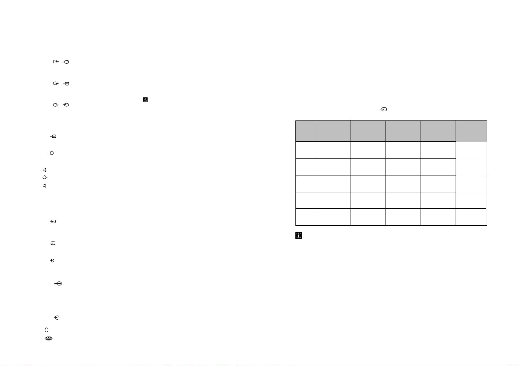
PC Input Specifications
PC Input Timing
Input signal frequency:
Horizontal: 15,6 - 90 KHz.
Vertical: 48 - 85 Hz.
Maximum Resolution: 1600 dots x -1200 lines.
Preset mode timing table for PC
No. Resolution
(dots x lines)
1 640x480 VESA 60 31.469 59.940
2 800x600 VESA 60 37.879 60.317
3 1024x768 VESA 60 48.363 60.004
4 1280x768 VESA (W-SVGA) 47.986 59.833
5 1280x1024 VESA 60 63.981 60.020
VGA-TEXT (720x400@70) cannot be available with this model. If you need any set up in your PC, please set
it up by using other display in advance.
Graphic mode Horizontal
frequency (KHz)
Vertical frequency
(Hz)
Horizontal/ Vertical
Negative/Negative
Positive/Positive
Negative/Negative
Positive/Negative
Positive/Positive
Polarity
RM-Y1012
MRX1
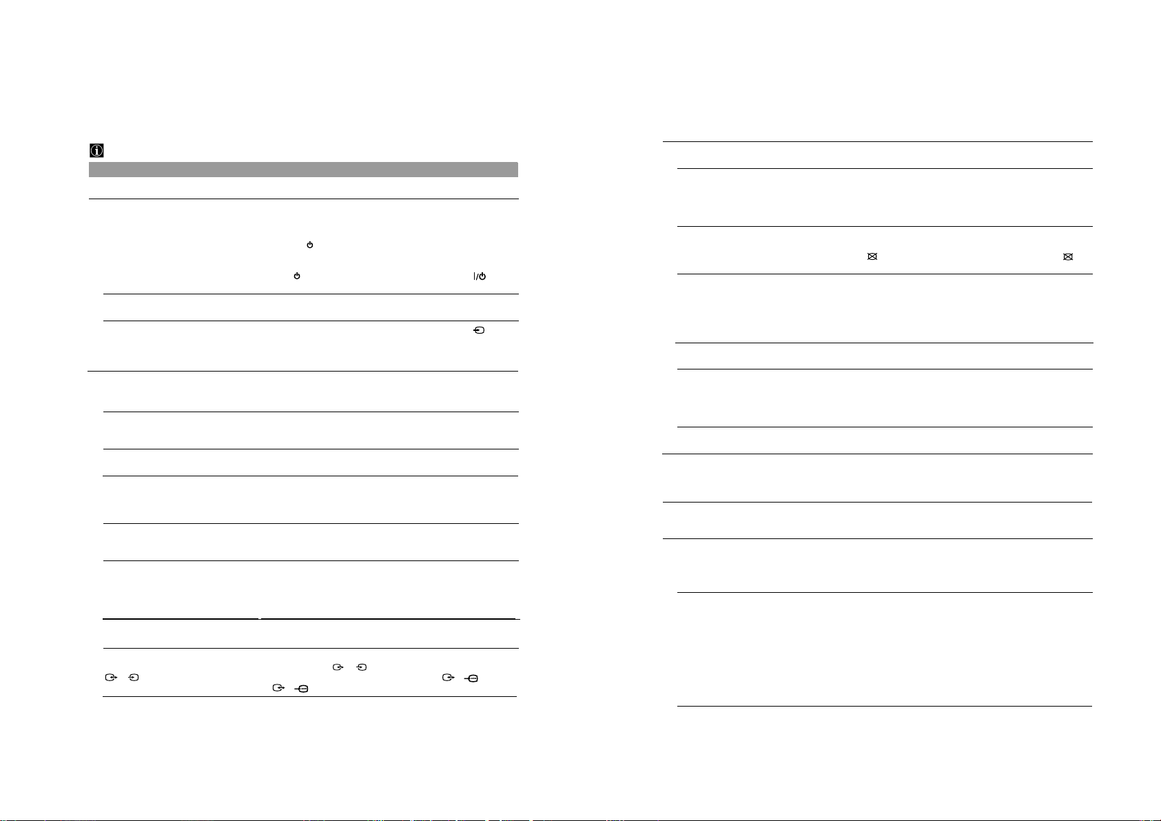
Troubleshooting
Here are some simple solutions to problems which may affect the picture and sound.
TV
Problem Possible solution
No picture
No picture (screen is dark) and no sound. • Check the aerial connection.
The TV turns off automatically. (The TV
enters the standby mode.)
No picture or no menu information from
equipment connected to the Scart
connector.
Poor picture/Unstable picture.
Double images or ghosting. • Check aerial/cable connections.
– 18 –
Only snow and noise appears on the
screen.
Dotted lines or stripes. • Keep the TV away from electrical noise sources such as cars,
No colour on colour programmes. • Using the menu system, select the “Picture Adjustment” menu and
Some tiny black points and/or bright
points on the screen.
The picture is too bright.
Picture (stripe) noise.
Poor picture (white saturation) when
viewing a signal from Scart connector
S
3/ .
• Connect the display unit and media receiver unit to the mains, and
press the power switch on the front of media receiver unit.
• Connect the display unit to the media receiver unit using the
supplied display interface cable.
• If the (power on/standby) indicator is on, press TV on the
remote control.
• Check if the Sleep Timer is activated (page 30).
• Check if Auto Shutoff is activated (page 30).
• Check that the optional equipment is on and press the button
repeatedly on the remote control until the correct input symbol is
displayed on the screen (page 52).
• Check the connection between the optional equipment and the TV.
• Check the aerial location and direction.
• Check if the aerial is broken or bent.
• Check if the aerial has reached the end of its serviceable life. (3-5
years in normal use, 1-2 years at the seaside)
motorcycles, or hair-dryers.
select “Reset” to return to the factory settings (page 23).
• If you set the Power Saving function to “Reduce,” picture colours
may become dimmer (page 26).
• The picture of a display unit is composed of pixels. Tiny black
points and/or bright points (pixels) on the screen, do not indicate a
malfunction.
• Using the menu system, select the “Picture Adjustment” menu and
select “Picture Mode” Then select the desired picture mode (page
22).
• Make sure that the aerial is connected using the supplied coaxial
cable.
• Keep the aerial cable away from other connecting cords.
• Do not use 300-ohm twin lead cables as interference may occur.
• Make sure that the output signal of the equipment connected to the
Scart connector 3/ is not an RGB signal. If it is an RGB
signal, please connect the equipment to Scart 1/ or
2/ .
S
Problem Possible solution
Distorted picture and/or noisy sound. • Check if any connected optional equipment is installed in close
Stripe noise during playback/recording
of a VCR.
Poor or no picture (screen is dark), but
good sound.
Noisy picture when viewing a TV
channel.
Distorted picture when changing
programmes or selecting teletext.
Only for PDP models: KE-P42MRX1,
KE-P50MRX1 and KE-P61MRX1
In the screen appears an image
retention (afterimage)
The screen flickers when turning on
the TV.
Wrong characters appear when viewing
teletext.
Wrong characters appear when viewing
NexTView.
No sound/Noisy sound.
Good picture, no sound. • Press the 2 +/– or % (mute) on the remote control.
Audio noise. • Make sure that the aerial is connected using the supplied coaxial
proximity of the TV set.
• Video head interference. Keep your VCR away from the TV.
• Leave a space of 30 cm between your VCR and the display unit to
avoid noise.
• Avoid installing your VCR in front of the display unit or at the side
of the display unit.
• Using the menu system, select the “Picture Adjustment” menu and
select “Reset” to return to the factory settings (page 23).
• If the PICTURE OFF indicator lights up in blue, press
(picture off) on the remote control.
• Using the menu system, select the “Manual Programme Preset”
option in the “Set Up” menu and adjust Fine Tuning (AFT) to
obtain better picture reception (page 35).
• Using the menu system, set the "Noise Reduction" option in the
“Picture Adjustment” menu to reduce the noise in the picture (page
23).
• Turn off any equipment connected to the Scart connector on the
rear of the media receiver unit.
• Using the menu system, select the “Features” menu, next select the
“Screen Saver” submenu and finally set the “All White” option to
“On” to reduce the image retention (see page 29).
• This is inherent in the Plasma Display Panel, and does not indicate
a malfunction.
• Using the menu system, enter the “Country” option in the “Set Up”
menu and select the country in which you operate the TV set (page
33). For Cyrillic languages, we recommend that you select Russia
if your own country does not appear in the list.
• Using the menu system, enter the “Language” option in the “Set
Up” menu and select the languge as the NexTView is broadcasted
(page 46).
• Check that “TV Speakers” option is set to “Main” in the “Sound
Adjustment” menu (page 25).
cable.
• Keep the aerial cable away from other connecting cords.
• Do not use 300-ohm twin lead cables as interference may occur.
• Communication problems may occur if the infrared communication
equipment (e.g. infrared cordless headphones) is used near the TV.
Please use headphones other than infrared cordless headphones,
move the infrared transceiver away from the TV until the noise is
eliminated, or move the transmitter and receiver of the infrared
communication equipment closer together.
continued...
continued...
RM-Y1012
MRX1
Problem Possible solution
The TV fan noise gets louder.
Cannot operate the menu.
Strange sound.
The TV cabinet creaks. • Changes in room temperature sometimes causes the TV cabinet to
The TV whirs. • The TV’s fan setting is working. This does not indicate a
The TV ticks. • An electrical circuit inside the TV is activated when the TV is
The TV buzzes. • There might be a surge sound when turning on the TV. This does
– 19 –
Remote Control
Remote control does not function.
v, V
, B and b buttons do not work in PAP
mode.
The (power on/standby) indicator
on the TV flashes.
• The ventilation holes can accumulate dust over a period of time.
The accumulated dust may make the cooling function of the builtin fan less effective. To prevent this, we recommend removing the
dust periodically (once a month) using a vacuum cleaner.
• If the item you want to select appears in a pale colour, you cannot
select it.
expand or contract, which can make slight noises. This does not
indicate a malfunction.
malfunction.
turned on. This does not indicate a malfunction.
not indicate a malfunction.
• Check that the Media Selector on the remote control is set correctly
for the device you are using (VCR, TV, DVD or AUX).
• If the remote control does not operate the VCR or DVD even when
the Media Selector has been set correctly, enter the necessary code
set as explained in “Remote Control Configuration for VCR or
DVD” on page 47.
• Replace the batteries.
• PAP navigation is only possible in TV mode, please check that
Media Selector is set to TV.
• Contact your nearest Sony service centre.
Personal Computer
Problem Possible solution
If the NO SYNC message appears on the
screen or if the (power on/standby)
indicator lights up in yellow
If the OUT OF RANGE message appears
on the screen
If using Windows
If using a Macintosh** system
Flickers, bounces, oscillates, or is
scrambled
Picture is fuzzy. • Using the menu system, adjust “Brightness” and “Contrast” in the
Picture is ghosting. • Eliminate the use of video cable extensions and /or video switch
®
*
• Check that the video signal cable is properly connected and all
plugs are firmly seated in their sockets.
• Check that the 15-Dsub video input connector’s pins are not bent
or pushed in.
Problems caused by the connected computer
• The computer is in power saving mode. Try pressing any key on
the computer keyboard.
• Check that the computer’s power is “on.”
• Check that the graphic board is completely seated in the proper bus
slot.
Problems caused by the connected computer
• Check that the video frequency range is within that specified for
the monitor. If you replaced an old monitor with this TV, reconnect
the old monitor and adjust the frequency range to the following:
Horizontal: 15.6 – 90 kHz
Vertical: 48 – 85 Hz
• If you replaced an old monitor with this TV, reconnect the old
monitor and do the following. Select 640 x 480 resolution at 60Hz
for Windows using the Windows device selection screen.
• When connecting a Macintosh computer, use an adapter (not
supplied) if necessary. Connect the adapter to the computer before
connecting the video signal cable.
• Using the menu system, select “Adjust Pixel” option in the “Screen
Control” menu and adjust “Dot phase” or “Total H Pixel”
(page 28).
• Try connecting the TV to a different mains socket, preferably on a
different circuit.
Problems caused by the connected computer
• Check your graphic board manual for the proper TV setting.
• Confirm that the graphic mode and the frequency of the input
signal are supported by this TV (page 55). Even if the frequency is
within the proper range, some graphics boards may have a sync
pulse that is too narrow for the TV to sync correctly.
• Adjust the computer’s refresh rate (vertical frequency) to obtain
the best possible picture.
“Picture adjustment” menu (page 22).
• Using the menu system, select “Adjust Pixel” option in the “Screen
Control” menu and adjust “Dot phase” or “Total H Pixel” (page
28).
Problems caused by the connected computer
• If the resolution is more than the numerical value specified in
“Technical Specifications” on page 53, the picture is reduced in
size and the picture quality may be less than the original. This is
not a malfunction.
boxes.
• Check that all plugs are firmly seated in their sockets.
continued...
continued...
RM-Y1012
MRX1
Problem Possible solution
Picture is not centred or sized properly. • Using the menu system, select the “PC Adjustment” option in the
Picture is too small. Problems caused by the connected computer
Wavy or elliptical pattern (moire) is visible. • Using the menu system, select the “PC Adjustment” option in the
Colour is not uniform. • Using the menu system, select the “PC Adjustment” option in the
The TV turns off after a while. Problems caused by the connected computer
* Windows® is a registered trademark of Microsoft corporation in the United States and other countries.
**Macintosh is a trademark licensed to Apple Computer, Inc., registered in the U.S.A. and other countries.
“Features” menu and adjust “V Size” (page 28).
• Using the menu system, select the “PC Adjustment” option in the
“Features” menu, then select the "Centering" option and adjust “H
Shift” or “V Shift” (page 28). Note that some graphic modes do not
fill the screen to the edges.
• Set the resolution of the connected computer to the same as the TV.
“Features” menu and adjust “Dot phase” or “Total H
Pixel”(page 28).
“Features” menu and adjust “Dot phase” or “Total H
Pixel”(page 28).
• Set the computer’s power saving setting to off.
– 20 –
"Memory Stick"
Problem Possible solution
Cannot insert the “Memory Stick” into the
“Memory Stick” slot.
Images from the “Memory Stick” can not
be displayed or you can view the image but
some features are not available and an
error message appears on the TV screen.
Cannot delete a file or all materials. • The write-protect switch on the “Memory Stick” is set to LOCK.
The image is not displayed • The image file is not DCF-compatible or MPEG - compatible.
• The “Memory Stick” is not facing in the correct direction. Insert
the “Memory Stick” with the b mark facing up into the “Memory
Stick” slot (page 38).
• This is not a malfunction of the TV. This is because you are using a
non-Sony brand “Memory Stick” media.
Release the lock.
• The image file is protected. Release the protection (pages 42-44).
• If you continue to experience problems, have your TV serviced by qualified personnel.
• Never open the casing yourself.
http://www.sony.net
Sony España, S.A.
IMPRESO EN ESPAÑA Dep. Leg. B-0000-2003 BENGAR - Granollers
RM-Y1012
MRX1
SECTION 2
DISASSEMBLY
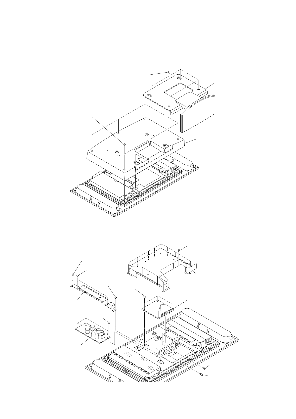
2-1. DISPLAY UNIT-1 (LDM-3210)
2-1-1. STAND ASSY AND REAR COVER REMOVAL
1
Four screws
(+PSW 5X14)
3
Five screws
(+BVTP 4X16)
Rear cover
4
2
Stand assy
MRX1
RM-Y1012
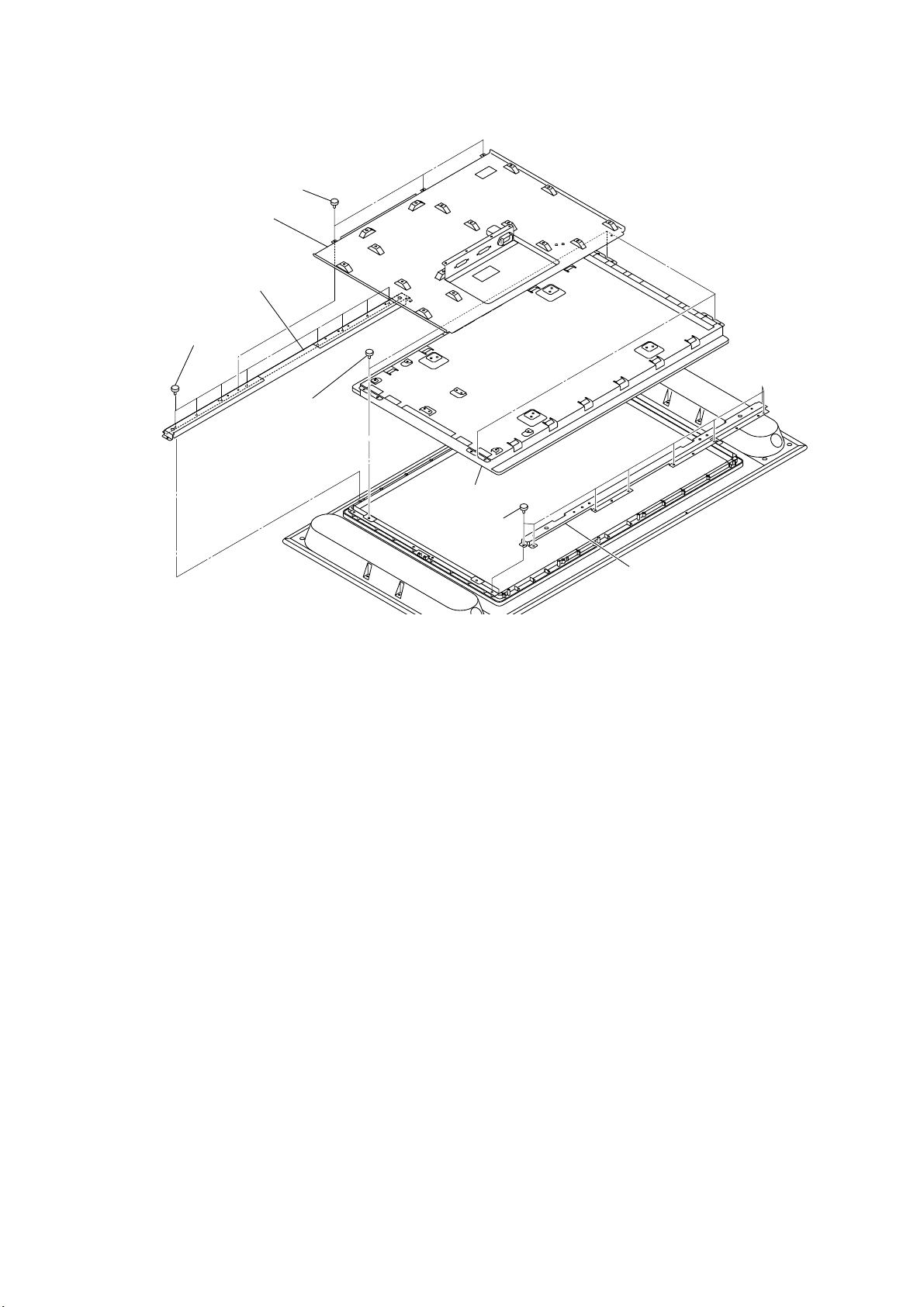
2-1-2. DES AND K BOARDS REMOVAL
Two screws
8
(+BVTT 4X10)
7
Four screws
(+PSW 5X10)
Two screws
8
(+BVTT 4X10)
Main arm S32 (R)
9
0
Five screws
(+BVTT 3X6)
qa
K board
Five screws
5
(+BVTT 3X6)
Twenty five screws
1
(+BVTT 3X6)
2
Shield case,S32 (center)
DES board
6
3
4
Two screws
(M2.6 S HEAD EG)
Two screws (HEX)
- 21 -
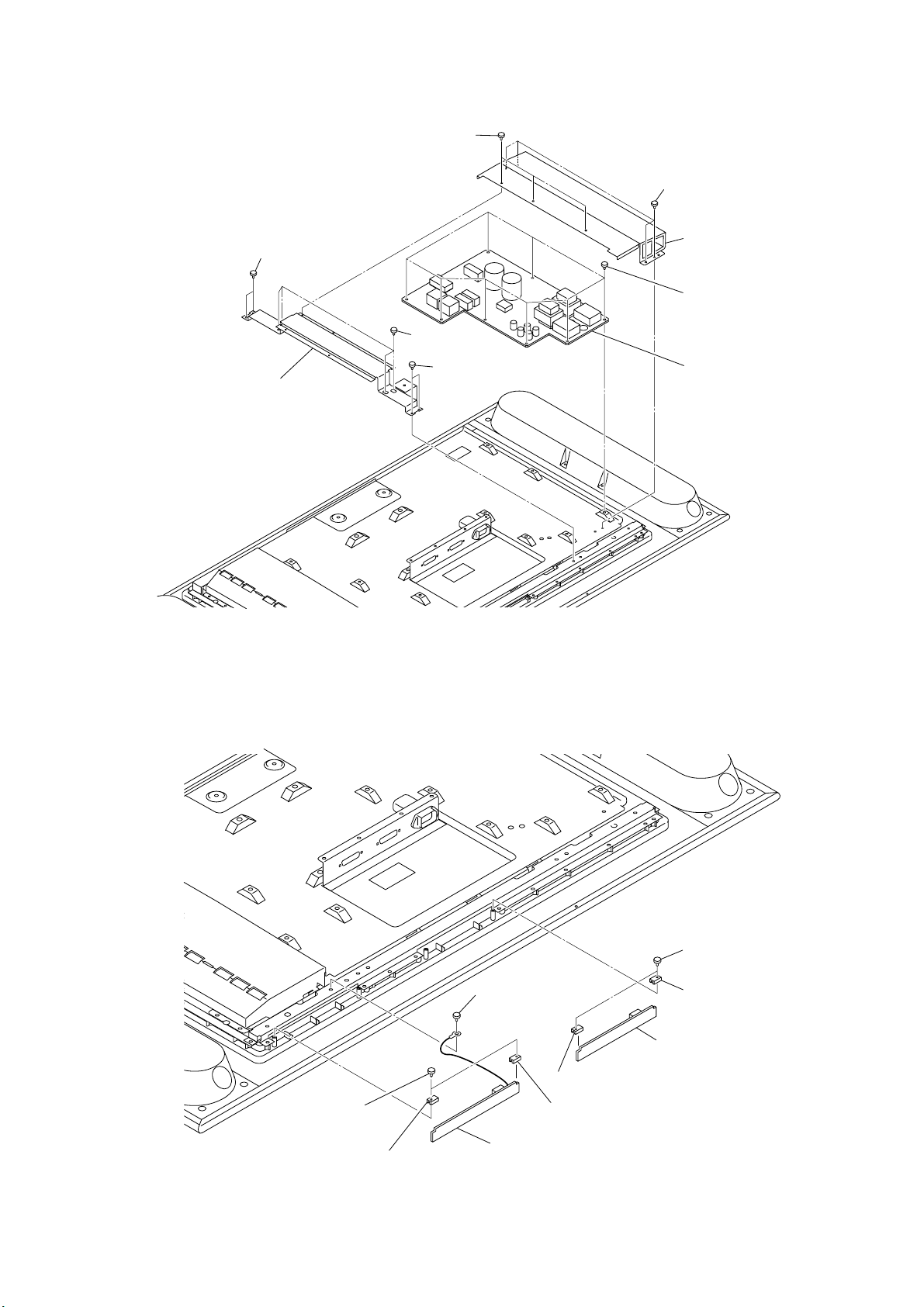
2-1-3. G1 BOARD REMOVAL
5
Two screws
(+BVTT 4X10)
Main arm S32 (L)
6
1
Three screws
(+BVTT 3X6)
4
Four screws
(+PSW 5X10)
5
Two screws
(+BVTT 4X10)
2
Four screws
(+BVTT 2.6X4)
3
Shield case 32(L)
7
Eight screws
(+BVTT 3X6)
G1 board
8
MRX1
RM-Y1012
2-1-4. R1 AND R2 BOARDS REMOVAL
Two screws
1
(+BVTP 3X12)
2
PWB-R bracket
3
Screw
(+BVTT 3X6)
4
R1 board
6
PWB-R bracket
2
7
R2 board
5
6
Two screws
(+BVTP 3X12)
PWB-R bracket
- 22 -
2-1-5. LCD PANEL REMOVAL
1
Three screws
(+BVTT 3X6)
Chassis
2
4
Panel support, S32 upper
Eight screws
3
(+BVTP 4X10)
Four screws
7
(+BVTT 4X10)
MRX1
RM-Y1012
LCD panel
8
5
Eight screws
(+BVTP 4X10)
6
Panel support, S32 lower
- 23 -
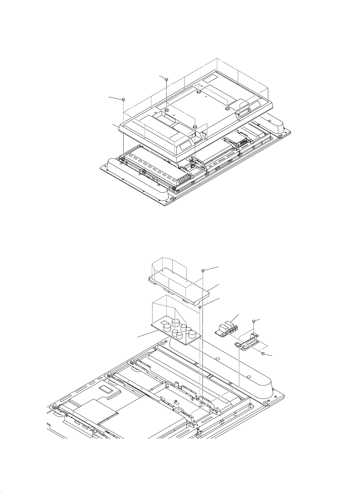
2-2. DISPLAY UNIT-2 (LDM-4210)
1
2-2-1. REAR COVER REMOVAL
1
Four screws
(+PSW 5X16)
2
Ten screws
(+BVTP 4X12)
3
Rear cover assy
MRX1
RM-Y1012
2-2-2. K1 AND K2 BOARDS REMOVAL
7
K1 board
1
Eight screws
(+BVTT 3X6)
Shield case
2
6
Five screws
(+BVTT 3X6)
K2 board
5
3
Two screws
(+BVTT 3X6)
4
Two screws
(+BVTP 3X
- 24 -
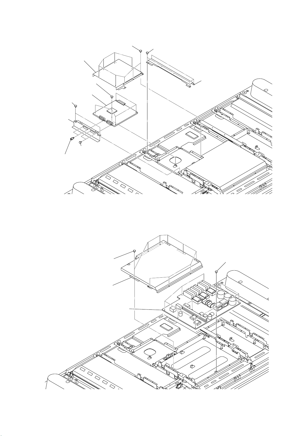
2-2-3. DES BOARD REMOVAL
3
4
Shield case
9
Five screws
(+BVTT 3X6)
DES board
7
Two screws
(+BVTT 3X6)
Terminal
8
bracket
Two screws (HEX)
5
0
6
Two screws
(M2.6 S HEAD EG)
Eight screws
(+BVTT 3X6)
1
Four screws
(+BVTT 3X6)
2
MRX1
RM-Y1012
Bracket
2-2-4. G2 BOARD REMOVAL
1
Nine screws
(+BVTT 3X6)
Shield case
2
G2 board
4
Nine screws
3
(+BVTT 3X6)
- 25 -
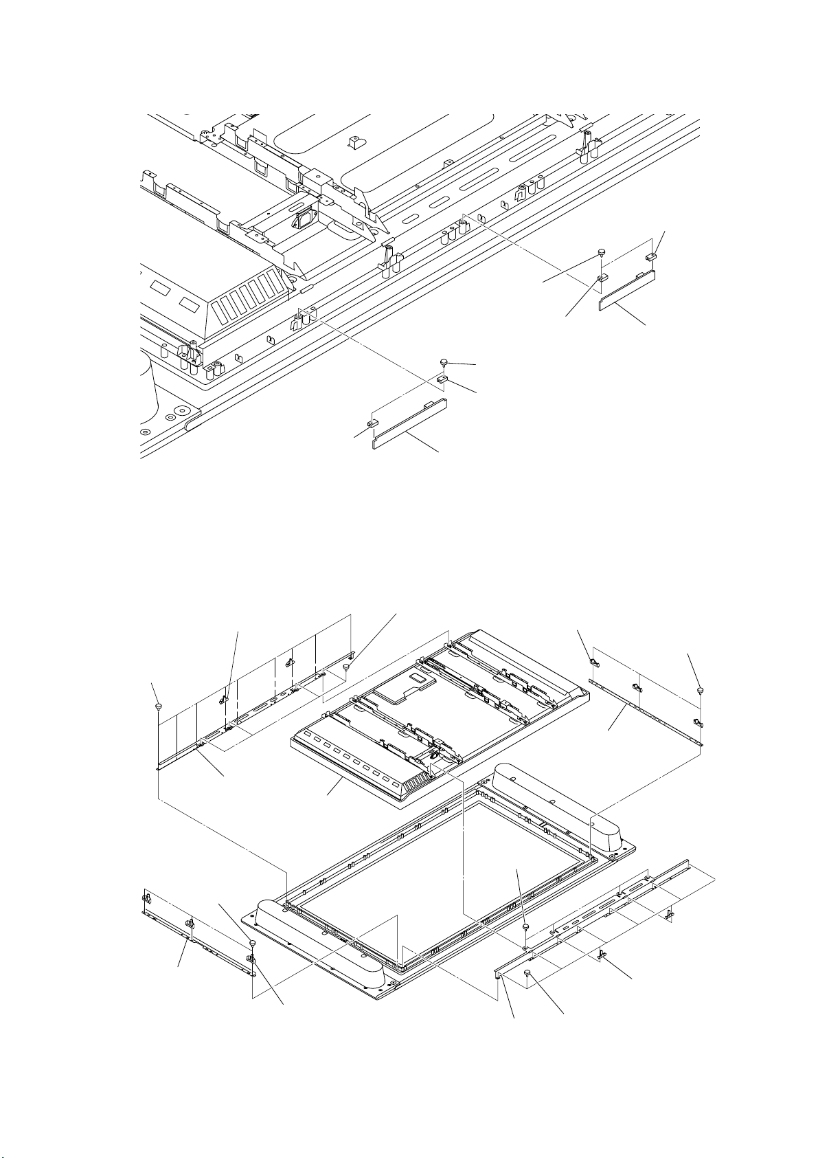
2-2-5. R3 AND R4 BOARDS REMOVAL
s
2
R
4
Two screws
(+BVTP 3X12)
1
Two screws
(+BVTP 3X12)
2
PWB-R bracket
5
PWB-R bracket
PWB-R bracket
5
6
R4 board
MRX1
RM-Y1012
2
PWB-R bracket
2-2-6. DISPLAY PANEL REMOVAL
Two holder(42H),REAR COVER
2
1
Nine screws
(+BVTP 4X12)
4
Support,panel(upper)
qg
LCD panel
3
3
Four screws
(+PTTWH 3X6)
R3 board
qd
Two holder(42V),
REAR COVER
qf
Support,panel(side)
qs
Three screw
(+BVTP 4X1
9
Three screws
(+BVTP 4X12)
Support,panel(side)
qa
q;
Two holder(42V),
REAR COVER
7
8
Support,panel(lower)
- 26 -
Four screws
(+PTTWH 3X6)
Two holder(42H),REAR COVE
6
5
Eight screws
(+BVTP 4X12)
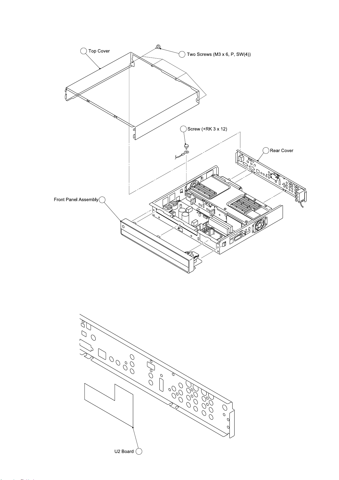
2-3. MEDIA RECEIVER UNIT (MBT-MRX1)
2-3-1. TOP COVER REMOVAL
MRX1
RM-Y1012
2
5
1
3
4
2-3-2. U2 BOARD REMOVAL
1
- 27 -
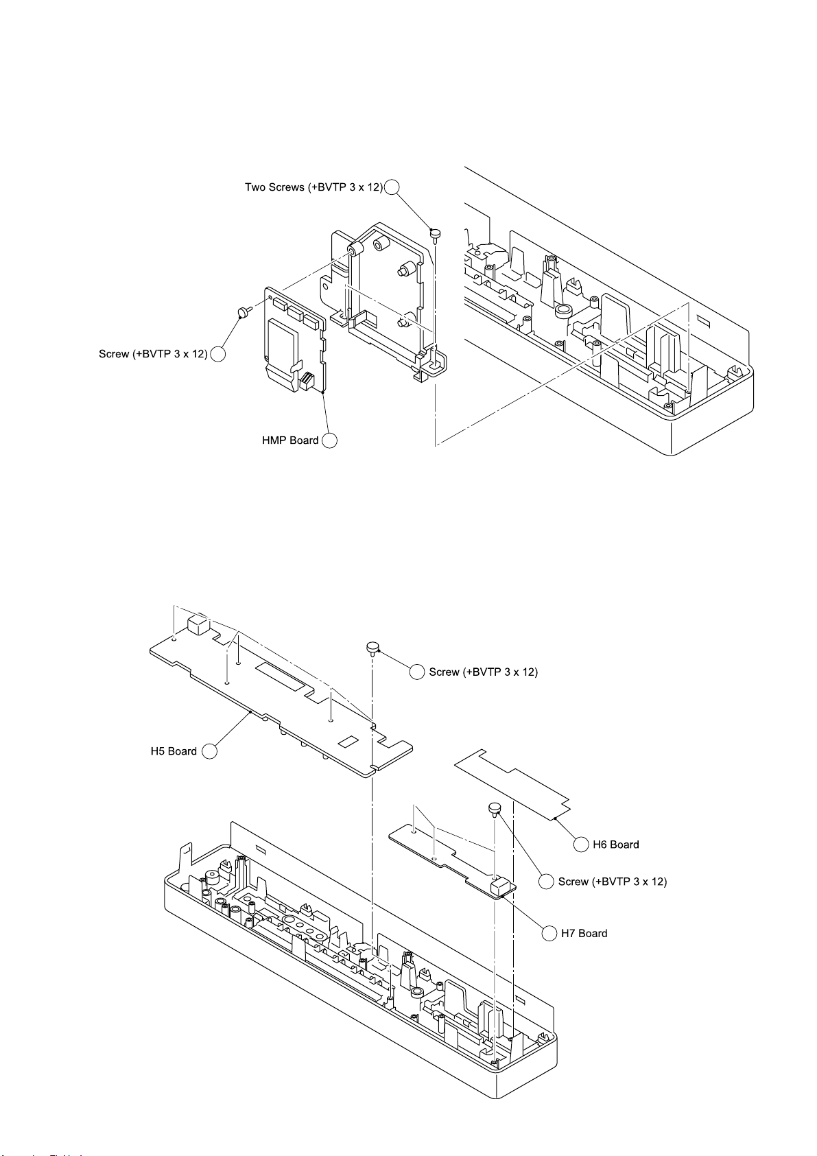
2-3-3. BASEPLATE AND HMP BOARD REMOVAL
2
MRX1
RM-Y1012
1
3
2-3-4. H5, H6 AND H7 BOARD REMOVAL
5
4
- 28 -
1
2
3
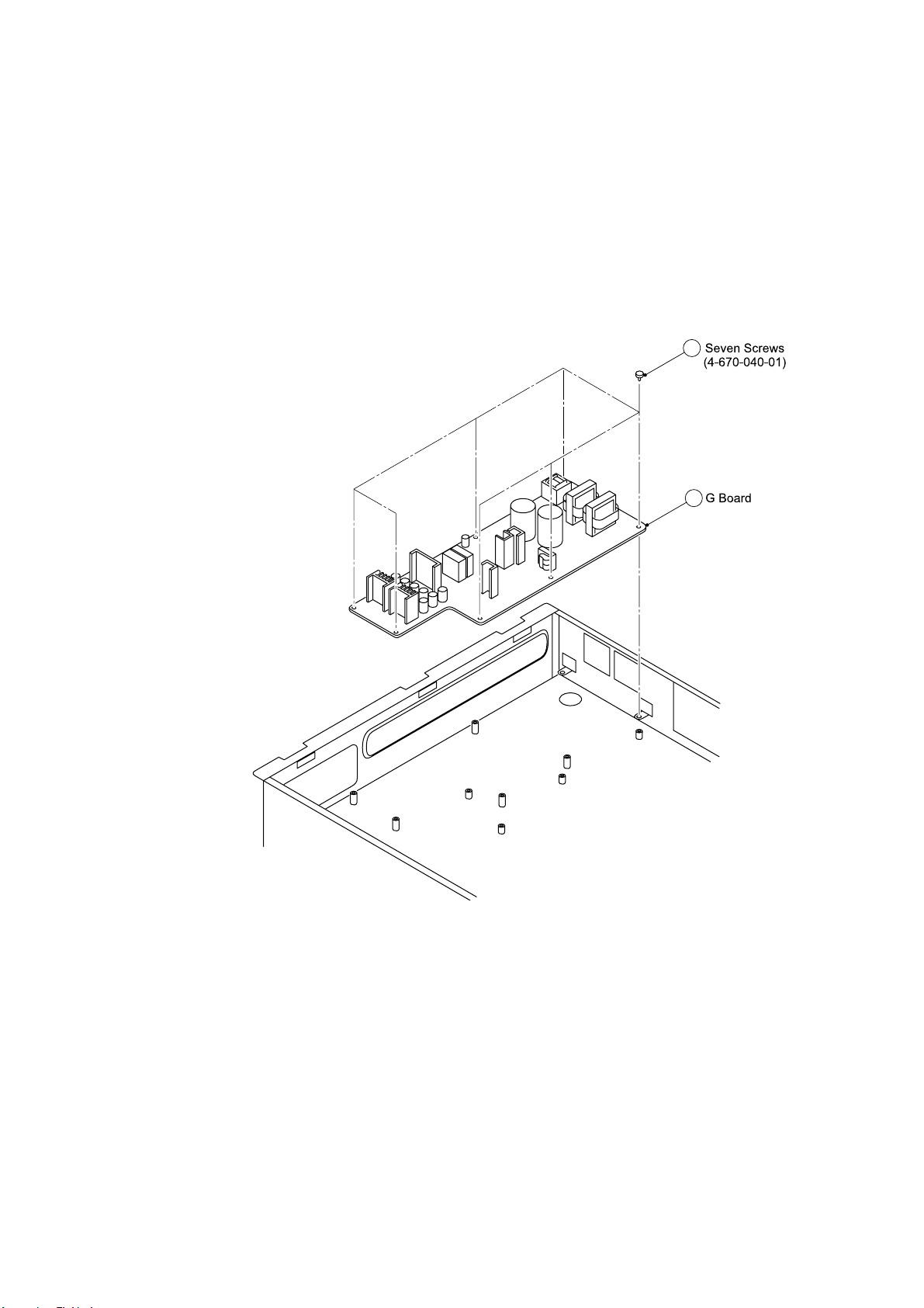
2-3-5. G BOARD REMOVAL
MRX1
RM-Y1012
1
2
- 29 -
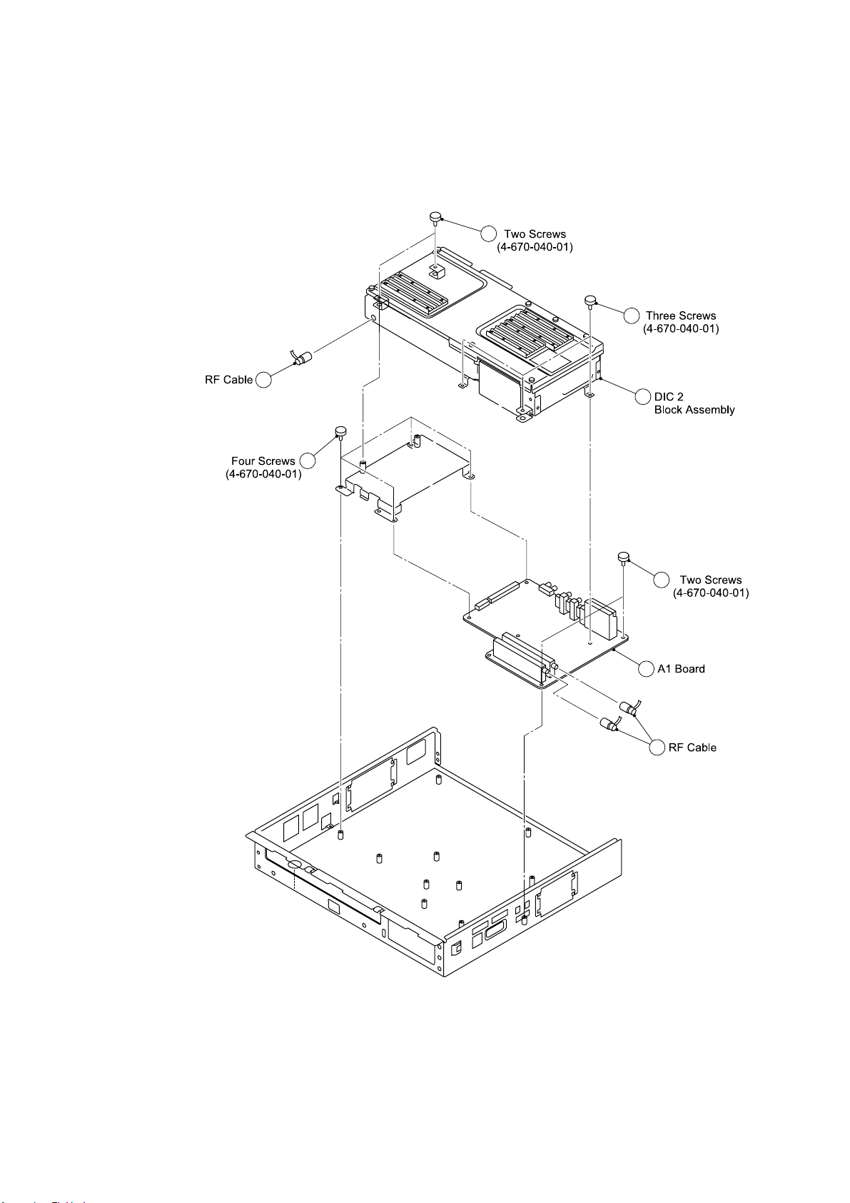
2-3-6. A1 BOARD REMOVAL
1
MRX1
RM-Y1012
2
3
4
5
6
7
8
- 30 -
 Loading...