

Sony KDL-32R434A Schematic
HISTORY INFORMATION FOR THE FOLLOWING MANUAL:
Self Diagnosis
Supported model
KDL-32R434A
Version Date Subject
1.0 09/19/2013 Original Manual Release Date.
RB1TK
Chassis
Segment: BA
MODEL COMMANDER DESTINATION
KDL-32R434A RM-YD093 BRAZIL
LCD Digital Color TV
9-883-540-01

TABLE OF CONTENTS
Cautions and Warnings ...................................................................................ii
Section 1 - Specifications and Layouts .........................................................1
Specifications ................................................................................................1
Board Layout .................................................................................................2
Wire Dressing ................................................................................................3
Section 2 - Troubleshooting ...........................................................................4
Diagnosing the Error .....................................................................................4
Viewing the Self Check Diagnosis History .............................................................4
Triage Chart ...................................................................................................5
Flowcharts and Diagrams ..............................................................................6
Overall Block Diagram ...........................................................................................6
Standby LED Blinking Flowchart ...........................................................................7
No Video Flowchart ...............................................................................................8
Video Distortion Flowchart .....................................................................................9
Section 3 - Repair Information ......................................................................10
Repairing the TV ..........................................................................................10
Removing the Table-Top Stand ............................................................................10
Removing the Lower Cover .................................................................................10
Replacing the Main Board ........................................................................... 11
Removing the Speakers ..............................................................................14
Removing the Bezel and H Board ...............................................................14
Section 4 - Exploded View/Part Number Information .................................15
KDL-32R434A .............................................................................................15
Connectors ..................................................................................................17
Screws .........................................................................................................18
Section 5 - Accessories/Part Number Information .....................................19
Accessories and Packaging ........................................................................19
Optional Accessories ...................................................................................19
Remote Commander ...................................................................................19
Appendix A: Encryption Key Components ............................................... A-1
KDL-32R434A i
CAUTIONS AND WARNINGS
CAUTION!!
These servicing instructions are for use by qualified service personnel only.
To reduce the risk of electric shock, do not perform any servicing other than
that contained in the operating instructions unless you are qualified to do so.
WARNING!!
An isolation transformer should be used during any service to avoid possible
shock hazard, in case of live chassis.
SAFETY-RELATED COMPONENT WARNING!!
!
There are critical components used in LCD color TVs that are important for
safety. These components are identified with shading and
schematic diagrams and the parts list. It is essential that these critical parts
be replaced only with the part number specified in the parts list to prevent
electric shock, fire or other hazard.
NOTE: Do not modify the original design without obtaining written permission
from the manufacturer or you will void the original parts and labor warranty.
mark on the
!
ATTENTION!!
For safety reasons, component level repair of the Power Supply Boards
and/or the Inverter Boards is prohibited.
SAFETY CHECK-OUT
After correcting the original service problem, perform the following safety
checks before releasing the set to the customer:
Check the area of your repair for unsoldered or poorly soldered
1.
connections. Check the entire board surface for solder splashes
and bridges.
Check the interboard wiring to ensure that no wires are “pinched” or
2.
touching high-wattage resistors.
Check that all control knobs, shields, covers, ground straps and
3.
mounting hardware have been replaced. Be absolutely certain that
you have replaced all the insulators.
Look for unauthorized replacement parts, particularly transistors,
4.
that were installed during a previous repair. Point them out to the
customer and recommend their replacement.
Look for parts which, though functioning, show obvious signs of
5.
deterioration. Point them out to the customer and recommend their
replacement.
Check the line cords for cracks and abrasion. Recommend the
6.
replacement of any such line cord to the customer.
Check the antenna terminals, metal trim, “metallized” knobs, screws
7.
and all other exposed metal parts for AC leakage. Check leakage
as described in “Leakage Test”.
KDL-32R434A ii
CAUTIONS AND WARNINGS
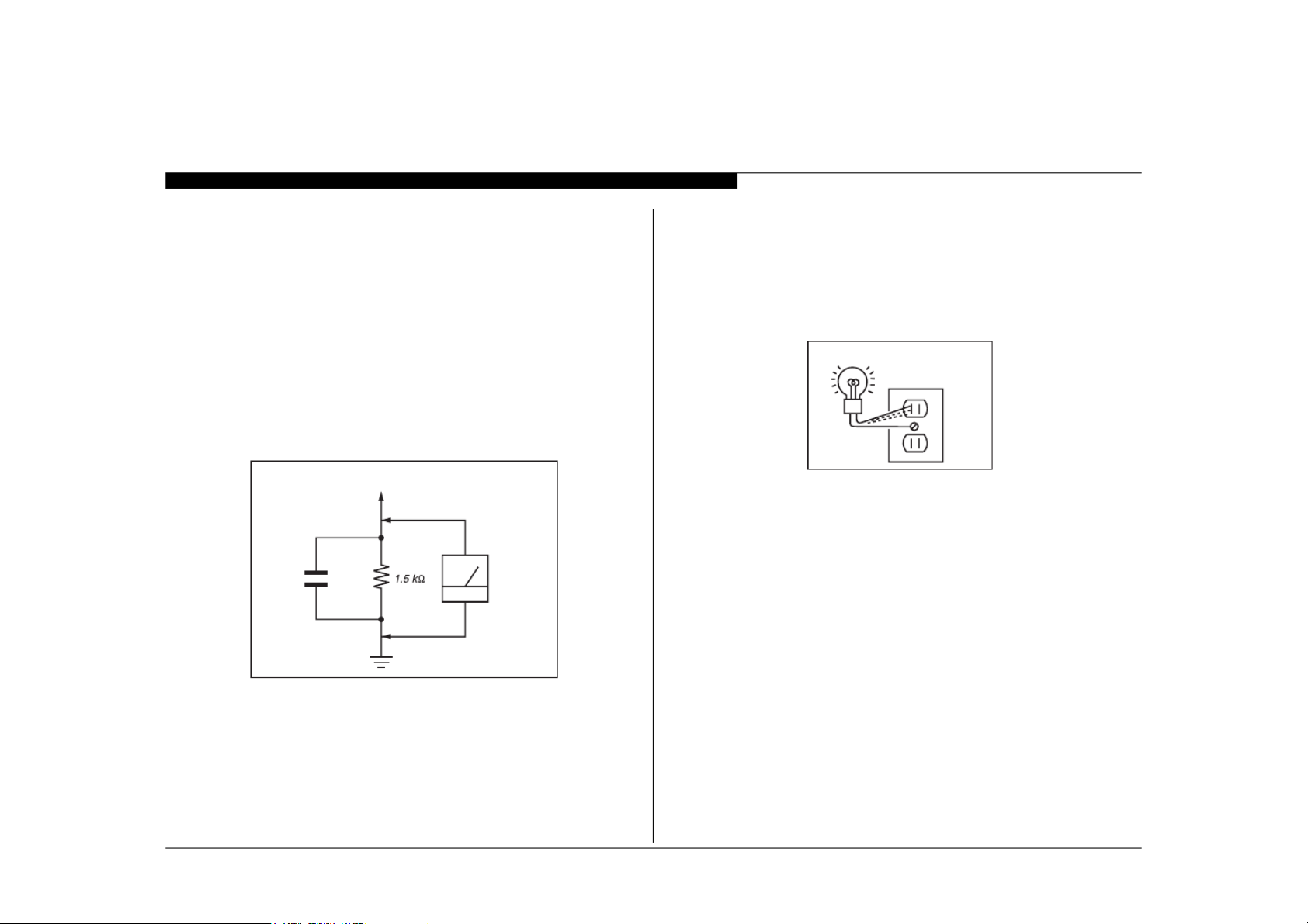
LEAKAGE TEST
The AC leakage from any exposed metal part to earth ground and from all
exposed metal parts to any exposed metal part having a return to chassis,
must not exceed 0.5 mA (500 microamperes). Leakage current can be
measured by any one of three methods.
A commercial leakage tester.
1.
Follow the manufacturers’ instructions provided with the tester.
A battery-operated AC milliammeter.
2.
Measuring the voltage drop across a resistor by means of a VOM
3.
or battery-operated AC voltmeter. The “limit” indication is 0.75 V, so
analog meters must have an accurate low voltage scale. Nearly all
battery-operated digital multimeters that have a 2 VAC range are
suitable. (see Figure A)
To Exposed Metal
Parts on Set
AC
0.15 µF
Voltmeter
(0.75V)
HOW TO FIND A GOOD EARTH GROUND
The cover-plate retaining screw on most AC outlet boxes is at earth ground.
Verify the AC outlet box retaining screw ground by connecting a 60W to
100W incandescent (not a neon or fluorescent lamp) between the hot side
of the receptacle and the retaining screw. Try both slots, if necessary, to
locate the hot side on the line; the lamp should light at normal brilliance if
the screw is at ground potential. (see Figure B)
Trouble Light
AC Outlet Box
Figure B. Checking for earth ground.
KDL-32R434A iii
Earth Ground
Figure A. Use an AC voltmeter to check AC leakage.
SECTION 1 - SPECIFICATIONS AND LAYOUTS
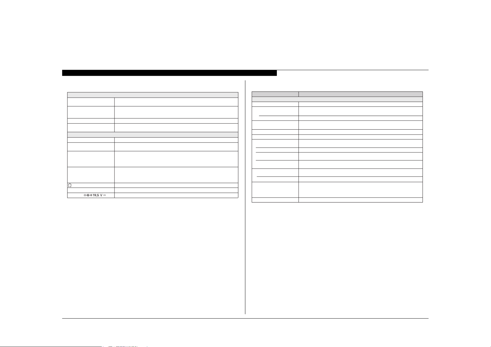
SPECIFICATIONS
Siste ma
Sistema de televisão Analógico: NTS C/PAL- M/PAL- N
Cobertura de c anal VHF: 2-13
Sistema do painel Painel LCD ( Tela de Cristal Líquido)/Backlight de LED
Potência de saída dos
Alto-f alantes (RMS)
Digital: SBTVD-T
UHF: 14-69
CATV: 1-135
5 W + 5 W
(127 V CA, THD* 10 % sinal 1 KHz, A lto-falante de 8 Oh ms, Nível de entrada 500 mVr ms)
Entr adas/Saíd as
CABLE/ANTENNA Terminal externo d e 75 ohms para entradas RF
VIDEO IN VÍDEO: 1 Vp- p, 75 ohms não balanceados , sincroniz ação negativa
COMPONENT IN (Vídeo c omponente): Y: 1,0 Vp- p, 75 ohms não balanceado , sincronizaç ão negativa /
HDMI IN 1/MHL HDMI: Vídeo: 480i, 480p, 576i, 576p, 720p, 1080i, 1080p, 1080/24p
AUDIO OUT Saída de áudio, Fones de ou vido (minitomada)
USB Foto, Música e V ídeo
Entrada DC Entrada do adaptador AC
ÁUDIO: 500 mVrms (Típico) / Impedância: 47 Kohms
YPBP
R
ÁUDIO: 500 mVrms (Típico) / Impedância: 47 Kohms
MHL: Vídeo: 480i, 480p, 576i, 576p, 720p, 720/30p, 1080i, 1080/30p, 1080/2 4p
Áudio: Dois ca nais lineares PCM 32, 44,1 e 48 kHz, 16, 20 e 24bits, Dolby Digital
Entrada do PC
PB: 0,7 Vp- p, 75 ohms /
Formato do sinal: 480i, 480p, 576i, 576 p, 720p, 1080i, 1080p
PR: 0,7 Vp- p, 75 ohms /
* Distorção Harmônica Total.
Nome do modelo KDL-32R434A
Energia e outros
Requisito de energia 110-220 V CA , 60 Hz
Consumo de energia
em uso
em modo de espera
Tama nho da tela Aprox . 80,0
(polegadas medidas diagonalmente) 31,5 (Classe 3 2)
Resolução de te la
Alto-f alantes/Ár ea total (2) 40 × 100
Dimensões
com pedestal
sem pedestal
padrão de f uro de montagem
da parede
tamanho de paraf uso de
montagem da parede
Peso
com pedestal
sem pedestal 5,0
Ac essórios f ornecidos
Ac essórios opc ionais
• A disponibilidade dos acessórios opcionais depende do estoque.
• Projeto e especificações técnicas sujeitos a alterações sem aviso prévio.
• Pesos e dimensões são aproximados.
(cm)
(mm)
(mm)
(mm)
(mm)
(mm)
(kg)
(kg)
Controle Remoto RM-YD093 (1) / Pilhas tamanho AA A (2) / Manual de Ins truções (1)
Guia Rápido (1) / Folheto de Instruç ões de Seguranç a (1) / Licenç a de Softw are ( 1)/Folheto Ginga (1)
Guia de Montagem do Pedestal (1) / Pedestal (1 c onjunto) / Parafus o (2) / Adapta dor AC
Suporte de Cabo (1 ) / Fixador do Ada ptador AC (2)
Cabos de Conexão/K it de Cinto de Seguranç a
61 W
Menos do que 1 W
735 × 471 × 171
735 × 446 × 75,5
100 × 100
M4 (6.5 - 10 mm)
5,2
linhas (ver tical)867×pontos (h orizontal)663,1
KDL-32R434A 1
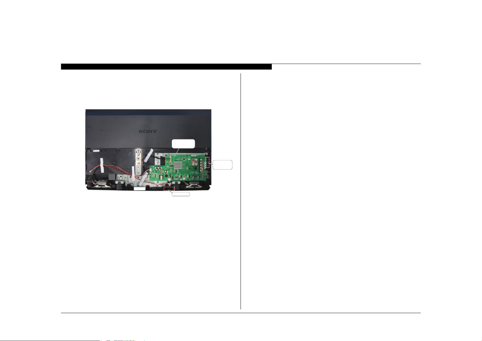
BOARD LAYOUT
KDL-32R434A
SECTION 1 - SPECIFICATIONS AND LAYOUTS
MAIN BOARD
(A BOARD)
SIDE JACK
COVER
KDL-32R434A 2
TCON
H BOARD

WIRE DRESSING
KDL-32R434AKDL-32R434A
SECTION 1 - SPECIFICATIONS AND LAYOUTS
KDL-32R434A 3
SECTION 2 - TROUBLESHOOTING
Self Diagnosis
Supported model
DIAGNOSING THE ERROR
Before servicing the Television:
Verify the TV has the symptom the customer indicated.
1.
Check to see if the latest Software is installed.
2.
If not, install the latest version.
a.
Determine the replacement part required.
3.
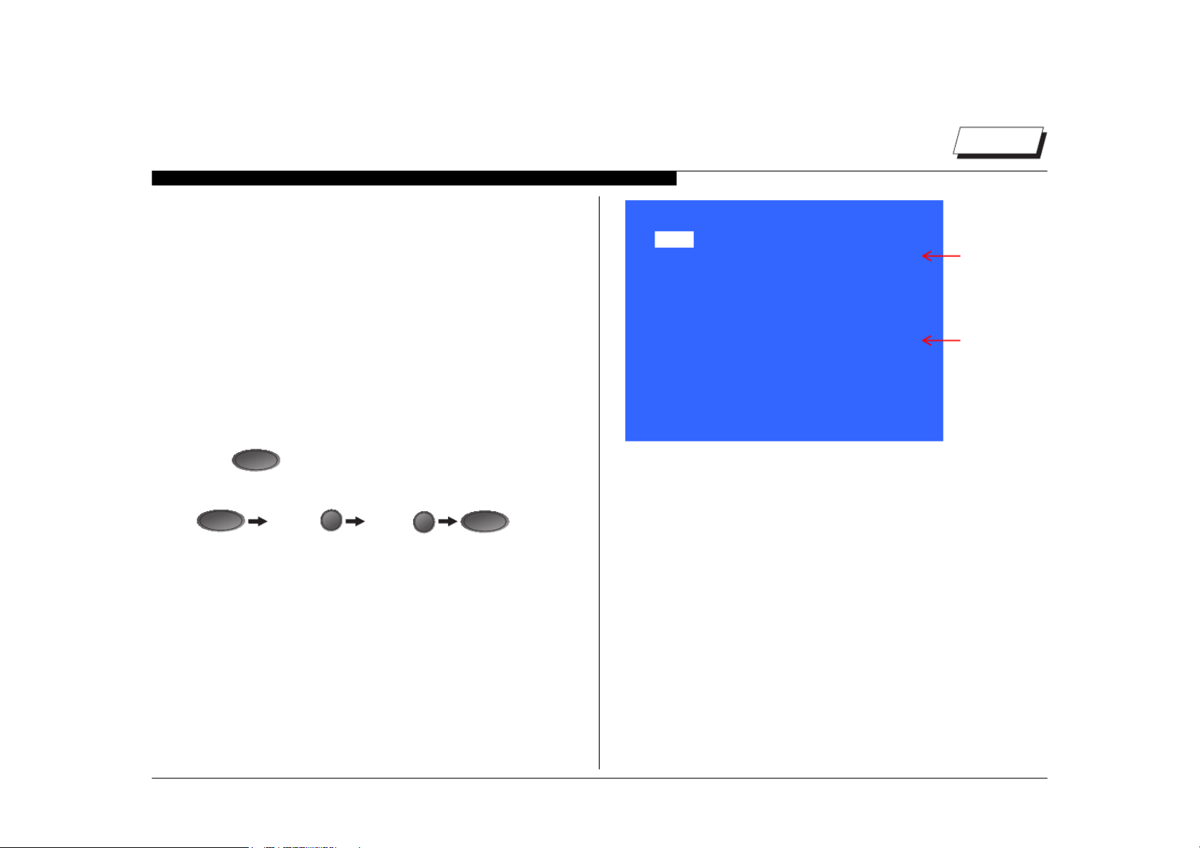
VIEWING THE SELF CHECK DIAGNOSIS HISTORY
When an error is detected, the Self Check screen records the number of
times the error occurred. This is helpful in confirming past occurrences of
an error and for determining if an error is intermittent when the customer is
not sure what is causing the television to shut down. If the screen displays
a “0”, no error has occurred.
Press
1.
Press the following buttons on the Remote Commander within 1
2.
second of each other:
DISPLAY
NOTE: This differs from accessing Service Adjustments Mode (Volume +).
to turn on the TV and then turn it off again.
POWER
Channel 5 Volume -
POWER
SELF CHECK
Back <<
002 MAIN_ POWER 001
003 DC_ALERT1 000
003 AUDIO_PROT
005 PANEL_ID_NVM_ERR
00116 00024 00115
[Home] Exit
SAMPLE SELF CHECK DIAGNOSIS PAGE
000
000
Indicates
an error
has occurred
000R_ERRECNALAB400
000RRE_NOCT500
Indicates
000TILKCAB600
000RRE_PMET700
no error
has occurred
KDL-32R434A 4
 Loading...