

Sony HXR-FMU128 Service Manual
HXR-FMU128
Sony EMCS Co.
SERVICE MANUAL
Revision History
Ver. Date History Contents
SERVICE NOTE (Check the following note before the service.)
985273911.pdf
2009K0500-1
© 2009.11
Published by Tokai TEC
Ver. 1.0 2009.11
FLASH MEMORY UNIT
The components identified
by mark or dotted line with
mark are critical for safety.
Replace only with part number
specified.
Les composants identifiés par
une marque sont critiques
pour la sécurité.
Ne les remplacer que par une
pièce portant le numéro spécifié.
HXR-FMU128
US Model
Canadian Model
AEP Model
Chinese Model
Japanese Model
—Official Release2009.111.0
9-852-739-11
1.0
1-1. PRECAUTIONS ON REPLACEMENT OF THE SSD
1-2. PRECAUTIONS ON REPLACEMENT OF THE BOARD
HXR-FMU128
– 2 –
SPECIFICATIONS
– ENGLISH – – JAPANESE –
概略仕様
This specifications is extracted from instruction
manual of HXR-FMU128.
この概略仕様はHXR-FMU128の取扱説明書から
抜粋しています。
System
File system FAT32
Memory 128 GB
When measuring media capacity, 1GB equals 1 billion bytes, a
portion of which is used for system management.
e capacity that a user can use is approximately 127GB.
General
Power
requirement
5V
Power
consumption
Approx. 0.9 W
Operating
temperature
0 °C to 40 °C (32 °F to 104 °F)
Storage
temperature
-20 °C to +60 °C (– 4 °F to +140 °F)
Operating
humidity
20 %(20 °C) to 90 % (35 °C)(no condensation)
Dimensions Approx. 54×85×17 mm (2 1/4×3 3/8×21/32 in.) (including the
projecting parts) (w/h/d)
Mass Approx. 80 g (2 oz.)
Input/output
jack
Connection jack
USB jack Hi-Speed USB (USB 2.0)
Supplied items USB cable (1), Case (1), Label (1), Warranty (1), Operating
instructions (1)
Design and speci cations are subject to change without notice.
ステム
ァイルシ ステム
FAT32
モリー
128 GB
容量は、
1 GBを10
億バイトで計算した場合の数値です。
また管理用ファイルなどを含むため、実際使用できる容量は
減少します 。ご使用頂けるユーザー容量は、約
127GB
です。
源部、その他
源電圧
5V
費電力 約
0.9 W
作温度0 °C〜
40 °C
存温度
-20 °C〜+60 °C
作湿度
20 %(20 °C)〜90 %(35 °C
)(結露がないこと)
形寸法 約54×85×
17 mm
(最大突起部を含む)(幅/高さ/奥行き)
量約80g
力出力端子 接続端子
USB端子
Hi-Speed USB (USB 2.0)
属品 USBケーブル(1)、ケース(1)、ラベル(1)、保証書(1)、取扱説明書
(
1
)、ソニー業務用商品相談窓口のご案内(1)
機の仕様および外観は、改良のため予告なく変更することがありますが、ご了承く
さい。
SAFETY-RELATED COMPONENT WARNING!!
COMPONENTS IDENTIFIED BY MARK OR DOTTED LINE WITH
MARK ON THE SCHEMATIC DIAGRAMS AND IN THE PARTS LIST
ARE CRITICAL TO SAFE OPERATION. REPLACE THESE COMPONENTS WITH SONY PARTS WHOSE PART NUMBERS APPEAR AS
SHOWN IN THIS MANUAL OR IN SUPPLEMENTS PUBLISHED BY
SONY.
SAFETY CHECK-OUT
After correcting the original service problem, perform the following
safety checks before releasing the set to the customer.
ATTENTION AU COMPOSANT AYANT RAPPORT
À LA SÉCURITÉ!
LES COMPOSANTS IDENTIFIÉS PAR UNE MARQUE SUR LES
DIAGRAMMES SCHÉMATIQUES ET LA LISTE DES PIÈCES SONT
CRITIQUES POUR LA SÉCURITÉ DE FONCTIONNEMENT. NE REMPLACER CES COMPOSANTS QUE PAR DES PIÈCES SONY DONT
LES NUMÉROS SONT DONNÉS DANS CE MANUEL OU DANS LES
SUPPLÉMENTS PUBLIÉS PAR SONY.
1. Check the area of your repair for unsoldered or poorly-soldered
connections. Check the entire board surface for solder splashes and
bridges.
2. Check the interboard wiring to ensure that no wires are “pinched”
or contact high-wattage resistors.
3. Look for unauthorized replacement parts, particularly transistors,
that were installed during a previous repair. Point them out to the
customer and recommend their replacement.
4. Look for parts which, through functioning, show obvious signs of
deterioration. Point them out to the customer and recommend their
replacement.
5. Check the B+ voltage to see it is at the values specified.
6. Flexible Circuit Board Repairing
• Keep the temperature of the soldering iron around 270˚C during
repairing.
• Do not touch the soldering iron on the same conductor of the circuit
board (within 3 times).
• Be careful not to apply force on the conductor when soldering or
unsoldering.
SAFETY CHECK-OUT
After correcting the original service problem, perform the following
safety checks before releasing the set to the customer.
Unleaded solder
Boards requiring use of unleaded solder are printed with the lead-free
mark (LF) indicating the solder contains no lead.
(Caution: Some printed circuit boards may not come printed with the
lead free mark due to their particular size.)
: LEAD FREE MARK
Unleaded solder has the following characteristics.
• Unleaded solder melts at a temperature about 40°C higher than ordinary
solder.
Ordinary soldering irons can be used but the iron tip has to be applied
to the solder joint for a slightly longer time.
Soldering irons using a temperature regulator should be set to about
350°C.
Caution: The printed pattern (copper foil) may peel away if the heated
tip is applied for too long, so be careful!
• Strong viscosity
Unleaded solder is more viscous (sticky, less prone to flow) than
ordinary solder so use caution not to let solder bridges occur such as
on IC pins, etc.
• Usable with ordinary solder
It is best to use only unleaded solder but unleaded solder may also be
added to ordinary solder.
1. 注意事項をお守りください。
サービスのとき特に注意を要する個所については,キャビ
ネット,シャーシ,部品などにラベルや捺印で注意事項を
表示しています。これらの注意書き及び取扱説明書等の注
意事項を必ずお守りください。
2. 指定部品のご使用を
セットの部品は難燃性や耐電圧など安全上の特性を持った
ものとなっています。従って交換部品は,使用されていた
ものと同じ特性の部品を使用してください。
特に回路図,部品表に印で指定されている安全上重要な
部品は必ず指定のものをご使用ください。
3. 部品の取付けや配線の引きまわしはもとどおりに
安全上,チューブやテープなどの絶縁材料を使用したり,
プリント基板から浮かして取付けた部品があります。また
内部配線は引きまわしやクランパによって発熱部品や高圧
部品に接近しないよう配慮されていますので,これらは必
ずもとどおりにしてください。
4. サービス後は安全点検を
サービスのために取外したネジ,部品,配線がもとどおり
になっているか,またサービスした個所の周辺を劣化させ
てしまったところがないかなどを点検し,安全性が確保さ
れていることを確認してください。
5. チップ部品交換時の注意
• 取外した部品は再使用しないでください。
• タンタルコンデンサのマイナス側は熱に弱いため交換時
は注意してください。
サービス,点検時には次のことにご注意ください。
6. フレキシブルプリント基板の取扱いについて
• コテ先温度を270℃前後にして行なってください。
• 同一パターンに何度もコテ先を当てないでください。(3
回以内)
• パターンに力が加わらないよう注意してください。
7. 無鉛半田について
無鉛半田を使用している基板には,無鉛(LeadFree)を意味
するレッドフリーマークがプリントされています。
(注意: 基板サイズによっては,無鉛半田を使用していても
レッドフリーマークがプリントされていないもの
があります)
:レッドフリーマーク
無鉛半田には,以下の特性があります。
• 融点が従来の半田よりも約40℃高い。
従来の半田こてをそのまま使用することは可能ですが,
少し長めにこてを当てる必要があります。
温度調節機能のついた半田こてを使用する場合,約
350℃に設定してください。
注意: 半田こてを長く当てすぎると,基板のパターン(銅
箔)がはがれてしまうことがありますので,注意
してください。
• 粘性が強い
従来の半田よりも粘性が強いため,IC端子などが半田ブ
リッジしないように注意してください。
• 従来の半田と混ぜて使用可能
無鉛半田には無鉛半田を追加するのが最適ですが,従来
の半田を追加しても構いません。
HXR-FMU128
1-1E
1. SERVICE NOTE
– ENGLISH –
1-1. PRECAUTIONS ON REPLACEMENT OF THE SSD
1. When replacing the SSD, connect the unit to your camcorder, and then format the SSD.
2. After formatting is complete, record movies to the unit to confirm that it is able to record movies.
3. After confirming, delete movies.
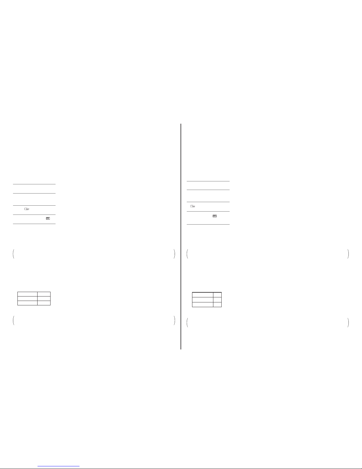
Formatting method:
– JAPANESE –
1-1. SSD交換時の注意
1. SSDを交換した場合は,本機をカムコーダーと接続し初期化(フォーマット)を行ってください。
2. 初期化(フォーマット)が終了したら本機に映像を録画し映像が記録できているかを確認します。
3. 確認後,映像を消去します。
初期化(フォーマット)方法:
記録メディアを初期化
する
bご注意
U
途中で電源が切れないように、ACアダプター
/
チャージャーを使ってコンセントから電源を
取ってください。
1
MODE
ボタンを押す。
2
[
MANAGE MEDIA
]→[
MEDIA
FORMAT
]をタッチする。
3
をタッチする。
4
[
YES
]→[
YES
]→をタッチ
する。
bご注意
U[Executing...
]が表示されているときは、電源
の入
/
切やボタンを操作したり、記録メディア
や
AC
アダプター/チャージャーを取り外した
ラスセクアは中化期初(。いさだくでいなしり
ンプが点灯・点滅します。)
Formatting the
recording media
b Notes
s Connect your camcorder to the wall out let (wall
socket) using the supplied AC Adaptor/Charger
to prevent your camcorder from running out of
power during the operation.
1 Press the MODE button.
2 Touch [MANAGE MEDIA] t
[MEDIA FORMAT].
3 Touch
4 Touch [YES] t [YES] t .
b Notes
s While [E xecuting...] is displayed, do not operate
the buttons on the camcorder, disconnect the AC
Adaptor/Charger, or remove the recording
media from your camcorder. (The access lamp
is lit or flashing while formatting recording
media.)
1-2. 基板交換時の注意
Note:
SSDは正常だが基板の不具合で修理する際は,組立後の動作確認の前に必要に応じて本機内のお客様が記録されたデータをバックアップしてく
ださい。
・基板を交換した場合は,下記の作業を行ってください。
1. カムコーダーと本機を接続し,電源を入れたときPOWERランプ(LED)が点灯していることを確認してください。
2. カムコーダーから本機に映像を記録してください。再生できることを確認したら記録した映像を削除してください。
記録中の動作確認:
1-2. PRECAUTIONS ON REPLACEMENT OF THE BOARD
Note: When performing repairs in cases where the SSD is operating normally but the board has malfunctioned, please backup any data that the customer has stored on
the unit as necessary before confirming operation after assembly.
• If the board has been replaced, perform the following operations:
1. Connect the unit to a camcorder, and check to make sure that the POWER lamp (LED) lights up when you turn on the power.
2. Save movies to the unit from the camcorder. After checking to make sure that the movies can be played, delete the saved movies.
Check operation of the following during recording:
Precautions to take when returning the unit to the customer:
Inform the customer that, when using the unit for the first time after repairs, they should make sure to first format it with the camcorder that they
are going to use.
Precautions to take when returning the unit to the customer:
Inform the customer that, when using the unit for the first time after repairs, they should make sure to first format it with the camcorder that they
are going to use.
お客様に返却する時の注意:
修理後初めて本機を使用する場合は,お客様がご使用になられるカムコーダーで必ず初期化(フォーマット)してからお使いいた
だくようお客様に注意を促してください。
お客様に返却する時の注意:
修理後初めて本機を使用する場合は,お客様がご使用になられるカムコーダーで必ず初期化(フォーマット)してからお使いいた
だくようお客様に注意を促してください。
LED STATUS
ACCESS lamp Flashing
REC lamp Lit
3. Connect the unit to a computer using the accompanying USB cable, and confirm that data (any random data will work) can be transferred and
written to and deleted from the unit.
LED 状態
ACCESSランプ 点滅
RECランプ 点灯
3. 付属のUSBケーブルで本機とパソコンを接続し,本機内にデータ(適当なデータで良い)を転送して書き込みと消去ができること
を確認してください。
HXR-FMU128
2-1
(ENGLISH)
NOTE:
• -XX, -X mean standardized parts, so they may have some differences from the original one.
• Items marked “*”are not stocked since they are seldom required for
routine service. Some delay should be anticipated when ordering
these items.
• The mechanical parts with no reference number in the exploded
views are not supplied.
• Due to standardization, replacements in the parts list may be different from the parts specified in the diagrams or the components
used on the set.
• CAPACITORS:
uF: µF
• COILS
uH: µH
• RESISTORS
All resistors are in ohms.
METAL: metal-film resistor
METAL OXIDE: Metal Oxide-film resistor
F: nonflammable
• SEMICONDUCTORS
In each case, u: µ, for example:
uA...: µA... , uPA... , µPA... ,
uPB... , µPB... , uPC... , µPC... ,
uPD..., µPD...
(JAPANESE)
【使用上の注意】
• ここに記載されている部品は, 補修用部品であるため,回路図及び
セットに付いている部品と異なる場合があります。
• -XX,-Xは標準化部品のため,セットに付いている部品と異なる場
合があります。
•*印の部品は常備在庫しておりません。
• コンデンサの単位でuFはμFを示します。
• 抵抗の単位Ωは省略してあります。
金 被:金属被膜抵抗。
サンキン:酸化金属被膜抵抗。
• インダクタの単位でuHはμHを示します。
• 半導体の名称でuA...,uPA...,uPB...,uPC...,uPD...等はそれぞれμA...,
μPA...,μPB...,μPC...,μPD...を示します。
• Color Indication of Appearance Parts
Example:
(SILVER) : Cabinet’s Color
(Silver) : Parts Color
• 外装部品色表示
例:
(SILVER):セットの色を表す。
(Silver) :部品の色を表す。
印の部品,または印付の点線で囲まれた部品は,
安全性を維持するために,重要な部品です。
従って交換時は,必ず指定の部品を使用してください。
• Abbreviation
AR : Argentine model
AUS : Australian model
BR : Brazilian model
CH : Chinese model
CND : Canadian model
EE : East European model
HK : Hong Kong model
J : Japanese model
JE : Tourist model
KR : Korea model
NE : North European model
The components identified by mark
or dotted line with mark are critical
for safety.
Replace only with part number specified.
Les composants identifiés par une
marque sont critiques pour la sécurité.
Ne les remplacer que par une pièce
portant le numéro spécifié.
When indicating parts by reference
number, please include the board name.
図面番号で部品を指定するときは基板名又はブロック
を併せて指定してください。
お願い
NOTE FOR REPAIR
• Make sure that the flat cable and flexible board are not cracked of
bent at the terminal.
Do not insert the cable insufficiently nor crookedly.
• When remove a connector, don’t pull at wire of connector. It is possible that a wire is snapped.
• When installing a connector, don’t press down at wire of connector.
It is possible that a wire is snapped.
• Do not apply excessive load to the gilded flexible board.
Cut and remove the part of gilt
which comes off at the point.
(Be careful or some
pieces of gilt may be left inside)
– JAPANESE –
– ENGLISH –
修理時の注意
• フラットケーブルおよびフレキシブル基板の端子面に欠け,折れ
等がないことを確認する。
また,コネクタへの接続は,差し込み不足や斜め差しにならない
ように注意する。
• コネクタを取り外す時に,線材部(極細)を持って引っ張ると断線
する恐れがありますので,絶対に線材部(極細)を持って引っ張ら
ないでください。
• 線材部(極細)を押さえながらコネクタを差し込むと,線材部(極細)
が断線する恐れがありますので,絶対に線材部(極細)には負担を
かけないでください。
• 金メッキされているフレキシブル基板には,強い負担をかけない
でください。
వ┵ߩ߇ࠇߚࡔ࠶ࠠㇱߪࠞ࠶࠻ߒߡ
㒰ߒߡߊߛߐޕ
㧔ࡔ࠶ࠠ⎕ ߇ࠦࡀࠢ࠲ౝߦᱷߞߡࠆ
႐ว߽ࠆߩߢᵈᗧߒߡߊߛߐ㧕
2. REPAIR PARTS LIST

HXR-FMU128
2-2
2-1. EXPLODED VIEWS
Ref. No. Part No. Description
Ref. No. Part No. Description
1 4-165-504-01 CABINET, UPPER
2 4-167-548-01 SHEET, EXT MUFFLE
* 3 1-458-178-11 SSD (128GB, THNS128GG4BNAA (PW))
4 A-1752-625-A FP-1146 FLEXIBLE BOARD, COMPLETE
5 A-1752-633-A ED-063 BOARD, COMPLETE (SERVICE)
* 6 4-165-940-01 SHEET, EXT LIGHT INTERCEPTION
7 1-837-240-11 CABLE, FLEXIBLE FLAT (FFC-194) (Note)
* 8 4-165-505-01 RETAINER, EXT CONNECTOR (F)
9 A-1752-631-A FP-1147 FLEXIBLE BOARD, COMPLETE (Note)
10 A-1752-624-A US-016 BOARD, COMPLETE
11 X-2541-503-1 CABINET ASSY, LOWER
12 X-2546-871-1 FRAME ASSY, EXT MAIN
#2 2-635-562-31 SCREW (M1.7)
#3 2-660-401-01 SCREW (M1.7), NEW TRU-STAR, P2
Note
Screw
#2
#2
#2
#2
#2
#3
#3
#3
1
2
3
4
10
5
6
8
7
(Note)
9
(Note)
11
12
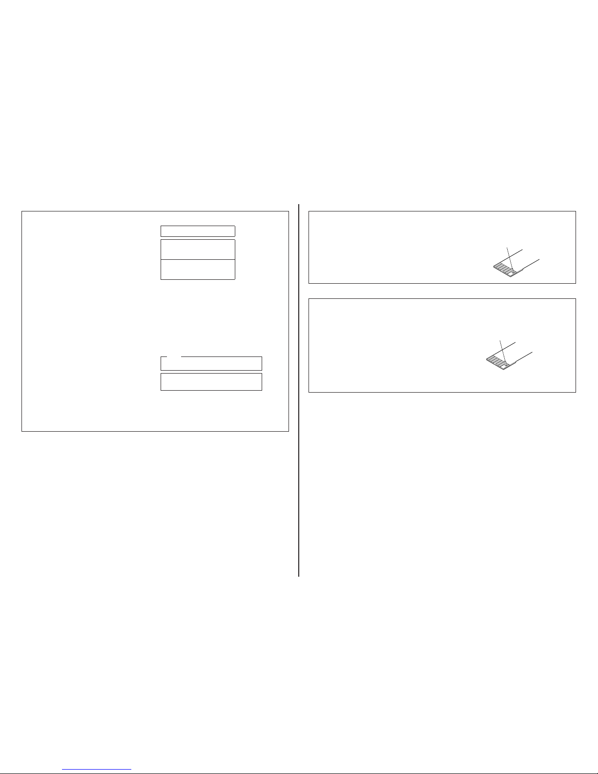
Note: When you install the FP-1147 flexible board or FFC-194, process
it as shown in figure below.
Note:
FP-1147フレキシブル基板及び,FFC-194を取付ける際は,下図
のように処理を行ってください。
FFC-194
EXT Connector Retaine
r
FP-1147Flexible Board
Push it into the hole of
EXT Connector Retainer.
Push it below of EXT
Connector Retainer.
EXTコネクタ押えの穴に押し込む。
EXTコネクタ押え
EXTコネクタ押えの
下に押し込む。
FP‑1147フレキシブル基板
FFC‑194
#2: M1.7 X 4.0
(Black)
2-635-562-31
4.0
1.7
#3: M1.7 X 2.5
(Red)
2-660-401-01
2.5
1.7
Checking supplied accessories.
Note: This item is supplied with the unit as an accessory,
but is not prepared as a service part.
SB Cable
1-829-868-31
Operating Instruction
(Note)
Label
(Note)
Case
4-165-502-01
付属品
Note:
当商品はアクセサリーとして同梱されておりますが
サービス用補修部品としては準備しておりません。
SBケーブル
1-829-868-31
ケース
4-165-502-01
ラベル
(Note)
取扱説明書
(Note)
 Loading...