

Sony HXCU-FB70 Operating Instructions Manual

4-445-032-11 (1)
HD Camera Control Unit
The supplied CD-ROM includes operating instructions for the HXCU-FB70 HD
Camera Control Unit in PDF format. For more details, see “Using the CD-ROM
manual” on page 5.
Operating Instructions
Before operating the unit, please read this manual thoroughly
and retain it for future reference.
HXCU-FB70
© 2012 Sony Corporation
Owner’s Record
WARNING: THIS WARNING IS APPLICABLE FOR USA
ONLY.
The model and serial numbers are located at the rear.
Record these numbers in the spaces provided below. Refer to
them whenever you call upon your Sony dealer regarding this
product.
Model No.
Serial No.
WARNING
To reduce the risk of fire or electric shock, do
not expose this apparatus to rain or moisture.
To avoid electrical shock, do not open the
cabinet. Refer servicing to qualified personnel
only.
THIS APPARATUS MUST BE EARTHED.
This symbol is intended to alert the user to
the presence of important operating and
maintenance (servicing) instructions in the
literature accompanying the appliance.
If used in USA, use the UL LISTED power cord specified
below.
DO NOT USE ANY OTHER POWER CORD.
Plug Cap Parallel blade with ground pin (NEMA 5-15P
Configuration)
Cord Type SJT, three 16 or 18 AWG wires
Length Minimum 1.5 m (4 ft. 11in.), Less than 2.5 m
(8 ft. 3 in.)
Rating Minimum 10A, 125V
Using this unit at a voltage other than 120V may require the
use of a different line cord or attachment plug, or both. To
reduce the risk of fire or electric shock, refer servicing to
qualified service personnel.
WARNING: THIS WARNING IS APPLICABLE FOR OTHER
COUNTRIES.
1. Use the approved Power Cord (3-core mains lead)/
Appliance Connector/Plug with earthing-contacts that
conforms to the safety regulations of each country if
applicable.
2. Use the Power Cord (3-core mains lead)/Appliance
Connector/Plug conforming to the proper ratings (Voltage,
Ampere).
This HD Camera Control Unit is classified as a CLASS 1
LASER PRODUCT.
Dieses HD-Kamera-Steuergerät ist als LASERPRODUKT
DER KLASSE 1 eingestuft.
Tämä HD-kameraohjausyksikkö on luokiteltu 1. LUOKAN
LASERTUOTTEEKSI.
Den här kontrollenheten för HD-kamera klassificeras som en
LASERPRODUKT AV KLASS 1.
CAUTION
Use of controls or adjustments or performance of procedures
other than those specified herein may result in hazardous
radiation exposure.
If you have questions on the use of the above Power Cord/
Appliance Connector/Plug, please consult a qualified service
personnel.
For kundene i Norge
Dette utstyret kan kobles til et IT-strømfordelingssystem.
For the customers in the U.S.A.
This equipment has been tested and found to comply with the
limits for a Class A digital device, pursuant to Part 15 of the
FCC Rules. These limits are designed to provide reasonable
protection against harmful interference when the equipment is
operated in a commercial environment. This equipment
generates, uses, and can radiate radio frequency energy and,
if not installed and used in accordance with the instruction
manual, may cause harmful interference to radio
communications. Operation of this equipment in a residential
area is likely to cause harmful interference in which case the
user will be required to correct the interference at his own
expense.
You are cautioned that any changes or modifications not
expressly approved in this manual could void your authority to
operate this equipment.
CAUTION
The use of optical instruments with this product will increase
eye hazard.
2
All interface cables used to connect peripherals must be
shielded in order to comply with the limits for a digital device
pursuant to Subpart B of Part 15 of FCC Rules.

This device complies with Part 15 of the FCC Rules. Operation
is subject to the following two conditions: (1) this device may
not cause harmful interference, and (2) this device must
accept any interference received, including interference that
may cause undesired operation.
For the customers in Canada
This Class A digital apparatus complies with Canadian ICES-
003.
For the customers in Europe
This product with the CE marking complies with the EMC
Directive issued by the Commission of the European
Community.
Compliance with this directive implies conformity to the
following European standards:
• EN55103-1: Electromagnetic Interference(Emission)
• EN55103-2: Electromagnetic Susceptibility(Immunity)
This product is intended for use in the following
Electromagnetic Environment: E4 (controlled EMC
environment, ex. TV studio).
For the customers in Europe, Australia and
New Zealand
WARNING
This is a Class A product. In a domestic environment, this
product may cause radio interference in which case the user
may be required to take adequate measures.
For the customers in Europe
The manufacturer of this product is Sony Corporation, 1-7-1
Konan, Minato-ku, Tokyo, 108-0075 Japan.
The Authorized Representative for EMC and product safety is
Sony Deutschland GmbH, Hedelfinger Strasse 61, 70327
Stuttgart, Germany. For any service or guarantee matters
please refer to the addresses given in separate service or
guarantee documents.
This apparatus shall not be used in the residential area.
For the State of California, USA only
Perchlorate Material - special handling may apply, See
www.dtsc.ca.gov/hazardouswaste/perchlorate
Perchlorate Material : Lithium battery contains perchlorate.
AVERTISSEMENT
Afin de réduire les risques d’incendie ou
d’électrocution, ne pas exposer cet appareil à
la pluie ou à l’humidité.
Afin d’écarter tout risque d’électrocution,
garder le coffret fermé. Ne confier l’entretien
de l’appareil qu’à un personnel qualifié.
CET APPAREIL DOIT ÊTRE RELIÉ À LA
TERRE.
AVERTISSEMENT:
1. Utilisez un cordon d’alimentation (câble secteur à 3 fils)/
fiche femelle/fiche mâle avec des contacts de mise à la
terre conformes à la réglementation de sécurité locale
applicable.
2. Utilisez un cordon d’alimentation (câble secteur à 3 fils)/
fiche femelle/fiche mâle avec des caractéristiques
nominales (tension, ampérage) appropriées.
Pour toute question sur l’utilisation du cordon d’alimentation/
fiche femelle/fiche mâle ci-dessus, consultez un technicien du
service après-vente qualifié.
Pour les clients au Canada
Cet appareil numérique de la classe A est conforme à la
norme NMB-003 du Canada.
Pour les clients en Europe
Ce produit portant la marque CE est conforme à la Directive
sur la compatibilité électromagnétique (EMC) émise par la
Commission de la Communauté européenne.
La conformité à cette directive implique la conformité aux
normes européennes suivantes:
• EN55103-1: Interférences électromagnétiques (émission)
• EN55103-2: Sensibilité électromagnétique (immunité)
Ce produit est prévu pour être utilisé dans l’environnement
électromagnétique suivant: E4 (environnement EMC contrôlé,
ex. studio de télévision).
Pour les clients en Europe, Australie et
Nouvelle-Zélande
For the customers in Taiwan only
AVERTISSEMENT
Il s’agit d’un produit de Classe A. Dans un environnement
domestique, cet appareil peut provoquer des interférences
radio, dans ce cas l’utilisateur peut être amené à prendre des
mesures appropriées.
3

Pour les clients en Europe
Le fabricant de ce produit est Sony Corporation, 1-7-1 Konan,
Minato-ku, Tokyo, 108-0075 Japon.
Le représentant autorisé pour EMC et la sécurité des produits
est Sony Deutschland GmbH, Hedelfinger Strasse 61, 70327
Stuttgart, Allemagne. Pour toute question concernant le
service ou la garantie, veuillez consulter les adresses
indiquées dans les documents de service ou de garantie
séparés.
Ne pas utiliser cet appareil dans une zone résidentielle.
WARNUNG
Um die Gefahr von Bränden oder elektrischen
Schlägen zu verringern, darf dieses Gerät
nicht Regen oder Feuchtigkeit ausgesetzt
werden.
Für Kunden in Europa, Australien und
Neuseeland
WARNUNG
Dies ist eine Einrichtung, welche die Funk-Entstörung nach
Klasse A besitzt. Diese Einrichtung kann im Wohnbereich
Funkstörungen verursachen; in diesem Fall kann vom
Betreiber verlangt werden, angemessene Maßnahmen
durchzuführen und dafür aufzukommen.
Für Kunden in Europa
Der Hersteller dieses Produkts ist Sony Corporation, 1-7-1
Konan, Minato-ku, Tokyo, 108-0075 Japan.
Der autorisierte Repräsentant für EMV und Produktsicherheit
ist Sony Deutschland GmbH, Hedelfinger Strasse 61, 70327
Stuttgart, Deutschland. Bei jeglichen Angelegenheiten in
Bezug auf Kundendienst oder Garantie wenden Sie sich bitte
an die in den separaten Kundendienst- oder
Garantiedokumenten aufgeführten Anschriften.
Um einen elektrischen Schlag zu vermeiden,
darf das Gehäuse nicht geöffnet werden.
Überlassen Sie Wartungsarbeiten stets nur
qualifiziertem Fachpersonal.
DIESES GERÄT MUSS GEERDET WERDEN.
WARNUNG
1. Verwenden Sie ein geprüftes Netzkabel (3-adriges
Stromkabel)/einen geprüften Geräteanschluss/einen
geprüften Stecker mit Schutzkontakten entsprechend den
Sicherheitsvorschriften, die im betreffenden Land gelten.
2. Verwenden Sie ein Netzkabel (3-adriges Stromkabel)/
einen Geräteanschluss/einen Stecker mit den geeigneten
Anschlusswerten (Volt, Ampere).
Wenn Sie Fragen zur Verwendung von Netzkabel/
Geräteanschluss/Stecker haben, wenden Sie sich bitte an
qualifiziertes Kundendienstpersonal.
Für Kunden in Europa
Dieses Produkt besitzt die CE-Kennzeichnung und erfüllt die
EMV-Richtlinie der EG-Kommission.
Angewandte Normen:
• EN55103-1: Elektromagnetische Verträglichkeit
(Störaussendung)
• EN55103-2: Elektromagnetische Verträglichkeit
(Störfestigkeit)
Für die folgende elektromagnetische Umgebung: E4
(kontrollierter EMV-Bereich, z.B. Fernsehstudio).
Dieser Apparat darf nicht im Wohnbereich verwendet werden.
4

Table of Contents
Overview .................................................................... 6
Features ..........................................................................6
System Configuration Example ......................................7
Preparations .............................................................. 9
Area Settings ..................................................................9
Settings when Connecting with Only Single-Mode Optical
Fiber Cable .................................................................. 9
Locations and Functions of Parts ......................... 10
Front Panel ................................................................... 10
Rear Panel .................................................................... 13
Status Display ......................................................... 15
Displaying the Status Screen ........................................ 15
Status Display Screen .................................................. 15
Setup Menu.............................................................. 18
Changing Menu Item Settings ......................................18
Menu Tree .................................................................... 20
Menu List ...................................................................... 22
Appendix.................................................................. 33
Notes on Use ................................................................33
About Transmission Distance .......................................33
Error Messages ............................................................ 33
Specifications ................................................................33
Using the CD-ROM manual
The manual can be read on a computer with Adobe
Reader installed.
You can download Adobe Reader free from the Adobe
website.
1 Open the index.html file in the CD-ROM.
2 Select and click on the manual that you want to
read.
Note
If you have lost or damaged the CD-ROM, you can purchase a
new one from your Sony dealer or Sony service counter.
Table of Contents / Using the CD-ROM manual
5

Overview
The HXCU-FB70 HD Camera Control Unit (CCU) connects to
the CA-FB70 HD Camera Adaptor that is attached to the HXCD70 HD Color Camera or PMW-500/350/320 Solid-State
Memory Camcorder. It performs signal processing, provides
an interface for external equipment, and supplies power to the
camera.
The CCU can be combined with an RCP-1000-series Remote
Control Panel (optional) to form a camera control system.
Features
1) HDMI, the HDMI logo and High-Definition Multimedia Interface are
trademarks or registered trademarks of HDMI Licensing, LLC.
Video inputs
• Reference input (HD/SD auto-select)
• VBS return input, 2-system
• SDI return input, 2-system
• VBS teleprompter input, 1-system
Audio inputs/outputs
• Audio output, 2-system (XLR-3-pin)
• Intercom headset input/output (XLR-5-pin)
• System intercom input/output (D-sub 25-pin)
– Intercom input/output, 2-system (PROD, ENG,
4W/RTS/CC selectable)
– PGM (program audio) input, 1-system
Long distance transmission via optical fiber
cable
• To connect the CA-FB70 HD Camera Adaptor to the CCU,
either a single-mode optical fiber cable or optical composite
cable can be used.
• When you use an optical composite cable to supply power
to the CA-FB70 HD Camera Adaptor and camera
/camcorder from the CCU, the connection distance can be
extended up to 250 m (820 ft)
mode optical fiber cable and mains to supply power to the
CA-FB70 HD Camera Adaptor and camera/camcorder, the
connection distance can be extended up to 10 km (32,800
ft)1).
• While the CCU is connected to the HXCE-FB70 Power
Supply Unit by a single-mode optical fiber cable (up to 10 km
(32,800 ft)), you can connect the CA-FB70 HD Camera
Adaptor and HXCE-FB70 Power Supply Unit with an optical
composite cable to supply power (up to 250 m (820 ft)) . The
adaptor offers flexibility to configure the camera system to
suit your usage environment.
1) The available power supply distance varies depending on the total
consumption of the connected peripherals such as
camera/camcorder, lens or accessory. For information on the
available distance, see “About Transmission Distance” on page 33.
1)
. When you use a single-
Easy-to-use control panel
The HXCU-FB70 has a fully-functional, ergonomicallydesigned front panel that includes basic adjustment of the
monitor image.
Other inputs/outputs
• TRUNK (RS-232C, D-sub 9-pin)
• REMOTE (8-pin, round)
• LAN (RJ-45, 8-pin)
• D-sub 25-pin inputs/outputs (shared with the system
intercom input/output connector)
– Tally input, 2-system (R/G)
– Tally output, 2-system (R/G)
– PREVIEW output
External sync signal input
The CCU can be locked to an external sync signal. Either an
HD tri-level sync signal or an SD sync (black burst) signal can
be used as the sync signal.
Built-in wideband down converter
HD signals from the camera can be converted to highresolution SD component SDI output signals using the
wideband down converter. The output signal aspect ratio can
be set to 4:3 edge crop, 16:9 squeeze, or letterbox.
Rack mountable
The CCU can be installed in a standard EIA 19-inch rack. The
height of the unit is 1.5U.
Multi-system input/output interface
The HXCU-FB70 includes the following input and output signal
connectors to manage various system setups.
Video outputs
• SDI (main), 2-system (HD/SD selectable, embedded audio)
• SDI (monitor), 2-system (HD/SD selectable, embedded
audio, superimposed character and marker display)
1)
• HDMI
• Analog composite (VBS 2-system, PIX 1-system)
• Analog component, 1-system (HD Y/Pb/Pr, HD R/G/B, SD
• S-VIDEO, 1-system
• Sync, 1-system (HD/SD selectable)
6
, 1-system (monitor)
Y/R-Y/B-Y, SD R/G/B 4-format selectable)
Overview
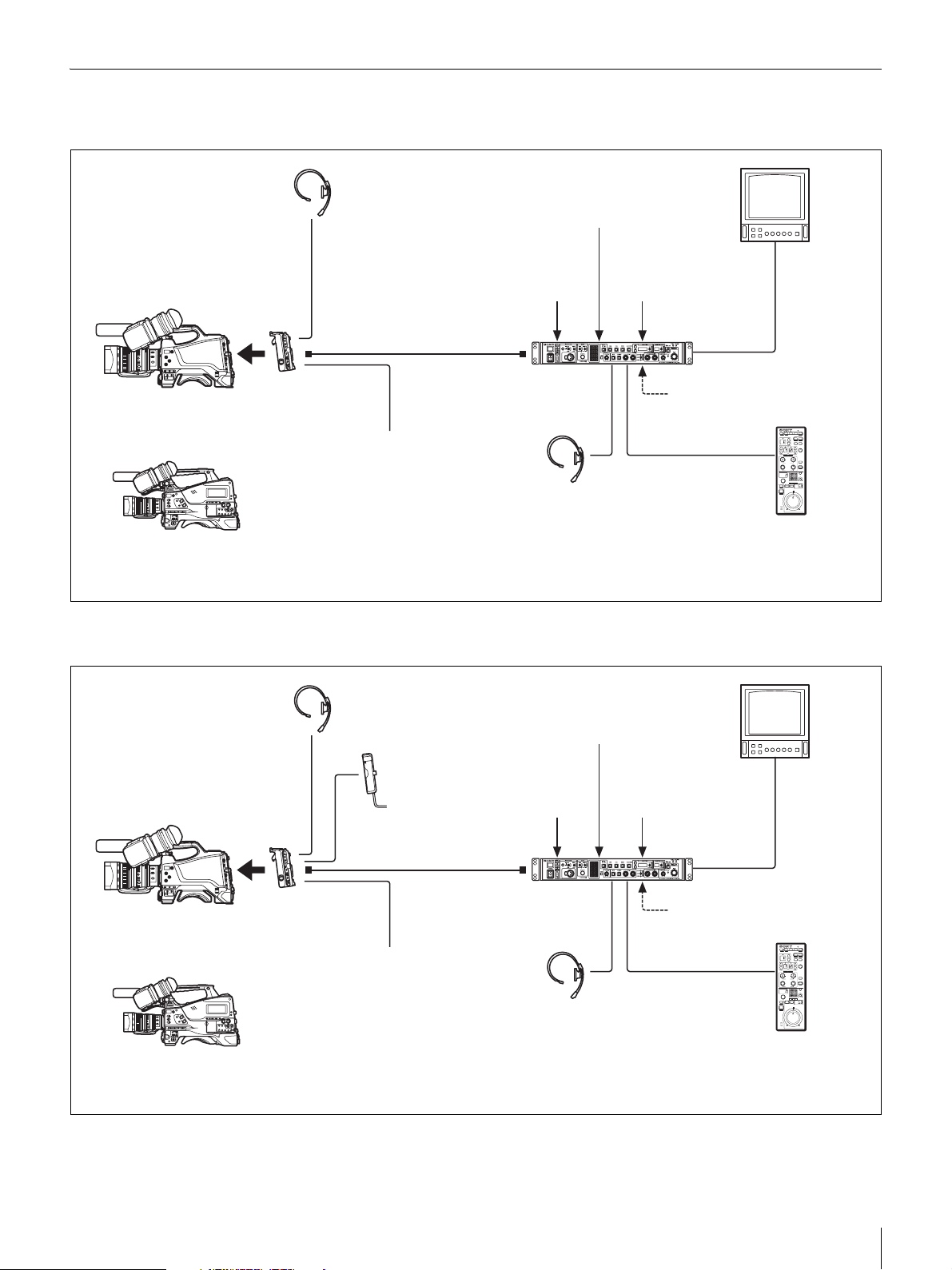
System Configuration Example
Connection using optical composite cable
Picture Monitor
HXC-D70
HD Color Camera
or
2)
PMW-500
Solid-State Memory Camcorder
/3503)/320
3)
Intercom Headset
Optical Composite Cable
CA-FB70
HD Camera Adaptor
Prompter
Video Output
1)
HXCU-FB70 HD Camera
Control Unit
Intercom Headset
Return Video Input
Sync Input
Prompter Video Input
HD SDI/SD SDI/VBS/
HDMI Video Outputs
AC Power
CCA-5 Cable/LAN Cable
RCP-1000-series
Remote Control Panel
1) The maximum transmission distance is 250 m (820 ft) when Sony CCFN-25/50/100 Hybrid Fiber Cable is used.
2) An optional CBK-HD02 SDI/COMPOSITE Input and 50 Pin Interface is required.
3) An optional CBK-CE01 50 Pin Interface and Digital Extender is required.
Connection using single-mode optical fiber cable only
For information on the setting, see “Settings when Connecting with Only Single-Mode Optical Fiber Cable” on page 9.
Picture Monitor
Intercom Headset
AC-DN2B/DN10
HXC-D70
HD Color Camera
CA-FB70
or
2)
PMW-500
Solid-State Memory Camcorder
1)
The maximum transmission distance is 10 km (32,800 ft) when a general single-mode optical fiber cable with an LC connector is used.
2)
An optional CBK-HD02 SDI/COMPOSITE Input and 50 Pin Interface is required.
3)
An optional CBK-CE01 50 Pin Interface and Digital Extender is required.
/3503)/320
HD Camera Adaptor
3)
AC Adaptor
Prompter
Video Output
HXCU-FB70 HD Camera
Control Unit
Return Video Input
Sync Input
Intercom Headset
Prompter Video Input
HD SDI/SD SDI/VBS/
HDMI Video Outputs
AC Power
CCA-5 Cable/LAN Cable
RCP-1000-series
Remote Control Panel
Overview
7
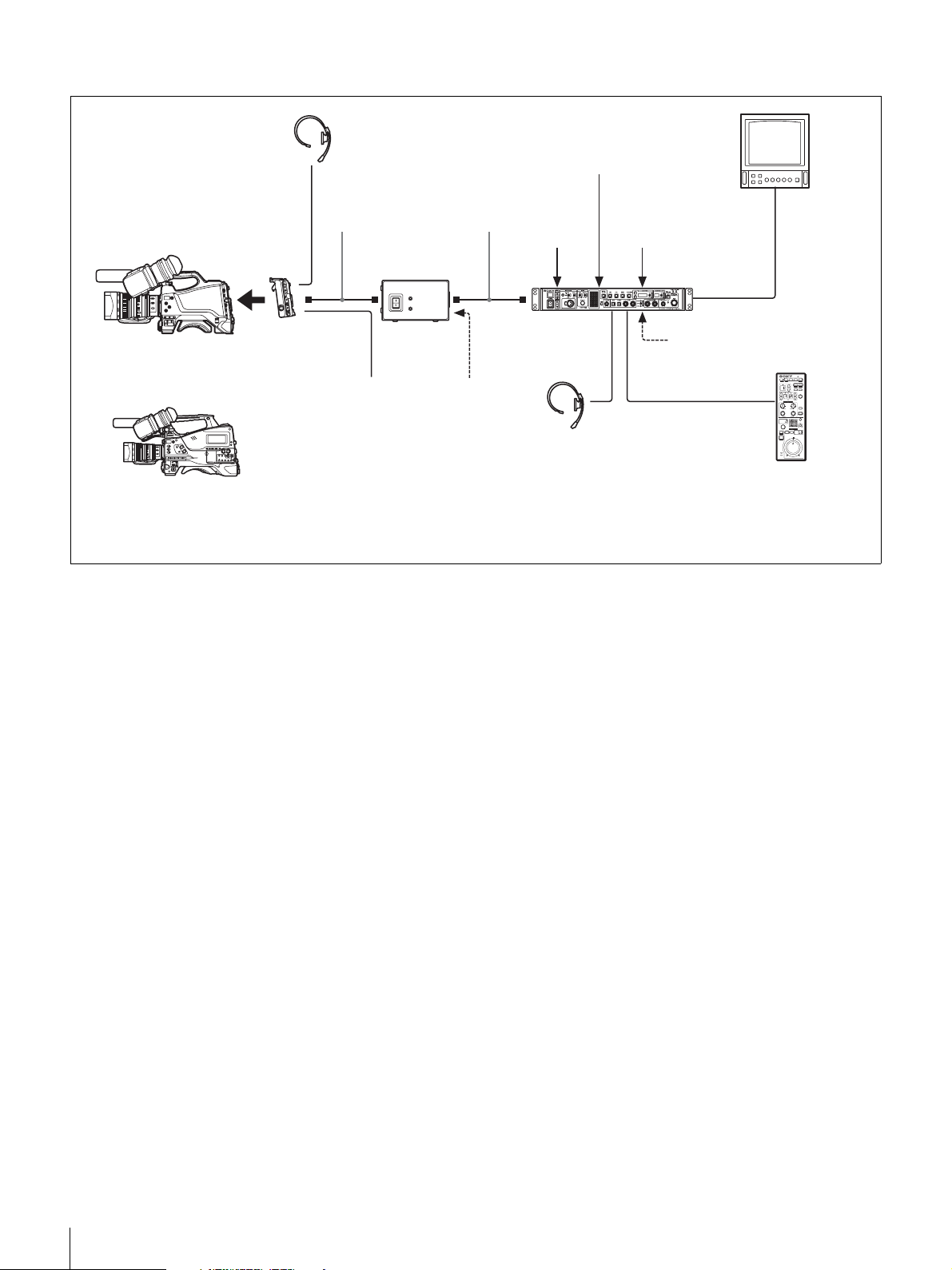
Connection using the HXCE-FB70 Power Supply Unit
Picture Monitor
Intercom Headset
Optical Composite
1)
HXC-D70
HD Color Camera
CA-FB70
or
3)
PMW-500
Solid-State Memory Camcorder
1)
The maximum transmission distance is 250 m (820 ft) when Sony CCFN-25/50/100 Hybrid Fiber Cable is used.
2)
The maximum transmission distance is 10 km (32,800 ft) when a general single-mode optical fiber cable with an LC connector is used.
3)
An optional CBK-HD02 SDI/COMPOSITE Input and 50 Pin Interface is required.
4)
An optional CBK-CE01 50 Pin Interface and Digital Extender is required.
/3504)/320
HD Camera Adaptor
4)
Cable
HXCE-FB70
Power Supply
Unit
Prompter
Video Output
Single-Mode Optical
Fiber Cable
AC Power
Return Video Input
2)
Sync Input
HXCU-FB70
HD Camera
Control Unit
Intercom Headset
Prompter Video Input
HD SDI/SD SDI/VBS/
HDMI Video Outputs
AC Power
CCA-5 Cable/LAN Cable
RCP-1000-series
Remote Control Panel
8
Overview
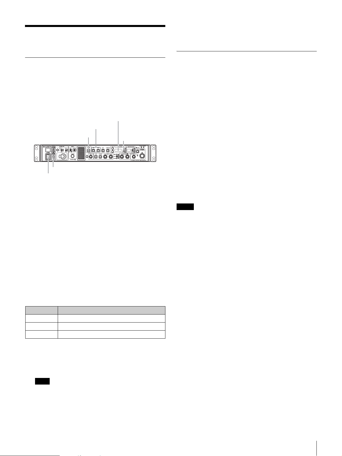
Preparations
Area Settings
“- - - - ” appears in the SHUTTER display five seconds after
setting. Area settings are stored and the units switches to
normal mode.
Settings when Connecting with Only Single-Mode Optical Fiber Cable
Before using the unit
When you use this unit for the first time, area setting is
required.
Setting the area
SHUTTER display
SW1, SW2 button
PANEL ACTIVE button
LOCK switch
POWER switch
UP/DOWN lever
1 Turn the p o w e r on .
2 Set the LOCK switch to OFF and make sure that the
PANEL ACTIVE button is not illuminated.
If the PANEL ACTIVE button lights up, press the button to
turn the light off.
3 Press and hold down the SW1 and SW2 buttons at the
same time for more than two seconds.
The unit switches to setting mode and selectable setting
values appear in the SHUTTER display.
4 Release the buttons after the unit switches to setting
mode.
LASER DIODE (optical output) setting
When you use only single-mode optical fiber cable to connect
the HD camera adaptor to this unit, configure the optical output
setting in the unit.
Setting LASER DIODE
1 Connect the unit and the HD camera adaptor by a
single-mode optical fiber cable.
2 Set the POWER switch of this unit to ON.
3 Display the menu.
For information on the menu setting, see “Setup Menu” on
page 18.
4 Set the optical output to ON.
Display the <OUTPUT SELECT>S01 page on SYSTEM
OPERATION menu, then set LASER DIODE to ON.
Notes
• This setting is unnecessary when you use optical composite cables.
• In the factory default setting, LASER DIODE is set to OFF when this
unit starts up. If you want to retain the LASER DIODE setting you
have previously set, from the CCU CONFIGURATION menu, select
<OTHERS> C12 page, LASER DIODE BACKUP, then set to
ENABLE.
• Use general, single-mode optical fiber cables with an LC connector
for connection. For details, please contact a Sony sales
representative.
5 Select the desired area, using the UP/DOWN lever,
within five seconds after the unit switches to setting
mode.
Settings Areas
60i5 NTSC (except Japan)
60i NTSC (Japan)
50i PA L
a) NTSC composite video signal output with a black setup (7.5 IRE).
System frequency: 59.94i
b) NTSC composite video signal output with no black setup. System
frequency: 59.94i
c) PAL composite video signal output. System frequency: 50i
Note
The setting mode is deactivated unless setting starts within five
seconds after the unit switches to setting mode. Follow step 3
again to activate setting mode.
c)
a)
b)
Preparations
9
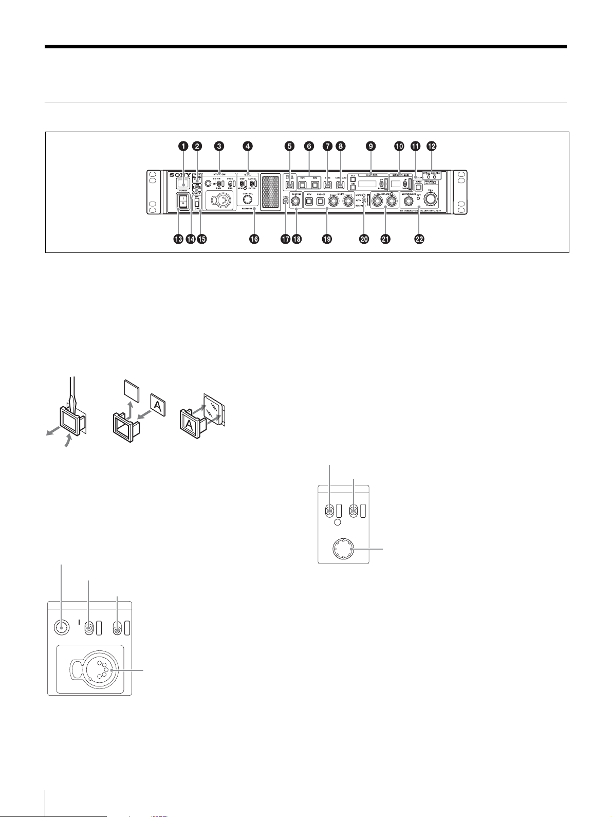
Locations and Functions of Parts
Front Panel
a Tally light
Turns on red to indicate a red tally signal is being received
(such as when the picture from the camera connected to the
CCU is being used). When the CALL button on the camera or
the RCP-1000- series Remote Control Panel is pressed, the
light turns off if lit or turns on if not lit.
Turns on green to indicate a green tally signal is being
received.
A number plate supplied with the CCU can be attached here
(see the following figure).
b CABLE ALARM indicators
OPEN: Turns on when a camera is not connected (open
circuit) to the CAMERA connector on the rear panel via a
fiber cable.
It flashes when there is a problem with the transmission
between the camera and the CCU.
c INTERCOM audio input/output and control block
INTERCOM (intercom adjustment) knob
MIC/PGM (microphone/program) switch
INTERCOM (intercom select) switch
INTERCOM
MIC-ON
OFF
PGM
PROD
ENG
INTERCOM
connector
• INTERCOM (intercom adjustment) knob
Adjusts the receiver audio level of the intercom.
• MIC/PGM (microphone/program) switch
ON: Turns the headset microphone on.
OFF: Turns the headset microphone off.
PGM: Selects program audio output. In this mode, the
INTERCOM knob adjusts the headset program audio level.
• INTERCOM (intercom select) switch
Selects the intercom signal input/output connection source for
the INTERCOM connector on the front panel.
PROD: Connects the producer line.
ENG: Connects the engineer line.
• INTERCOM connector (XLR 5-pin)
Connects the intercom headset.
For information on pin assignment, see “INTERCOM” in “Pin
assignment” on page 35.
d MENU control block
DISP/MENU (display/menu) lever and indicator
CANCEL/ENTER lever
MENU
DISP CANCEL
MENU ENTER
CONTROL
CONTROL knob
• DISP/MENU (display/menu) lever and indicator
Selects the status display or setup menu display. In setup
menu mode, the indicator turns on.
• CANCEL/ENTER lever
In setup menu mode, used to cancel and enter settings.
• CONTROL knob (rotary encoder)
In status screen mode, used to change the displayed page.
In setup menu mode, used to move the cursor on a page and
to change menu settings. Pressing the CONTROL knob
performs the same function as setting the CANCEL/ENTER
lever to the ENTER position.
Locations and Functions of Parts
10
e PANEL ACTIVE button
Activates the control panel to control the camera connected to
the CCU (panel active state). When the button is lit, the
IRIS/MB ACTIVE indicator also turns on simultaneously.
When the button is not lit, the panel is deactivated (panel lock
state) to prevent inadvertent operation.
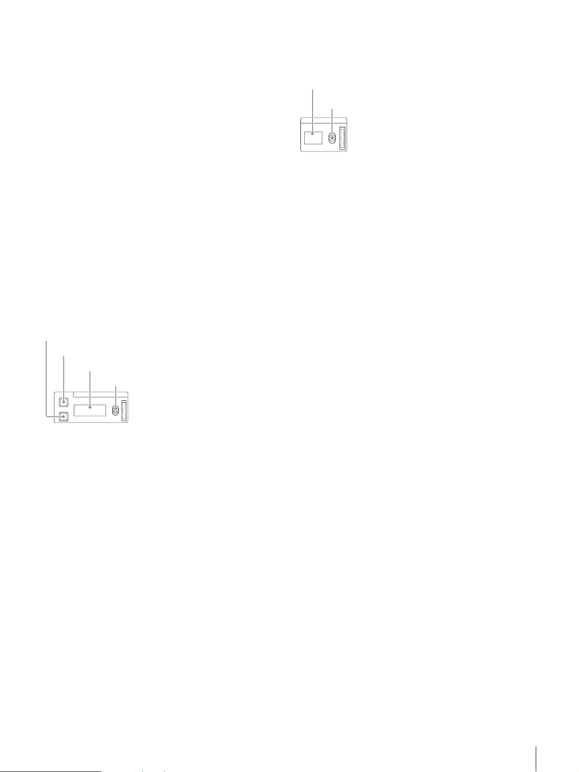
j MASTER GAIN control block
Controls the video output signal gain in response to the
lighting of the subject.
Display
UP/DOWN lever
f SW1, SW2 (assignable switch 1, 2) buttons
Controls the function assigned to each button on the <FRONT
PANEL 1> page in the CCU CONFIGURATION menu. The
button light turns on/off as the assigned function is switched
on/off.
See “ASSIGNABLE/CUSTOM” on <FRONT PANEL 1> on
page 29.
g BARS (color bars) button
Switches on the color bar signal output to the monitor
connected to the CCU (button light turns on). Pressing the
button again restores the previous signal output.
h STANDARD button
Stores the current camera settings as the reference file data
values in the camera (button light turns on for a few seconds).
While the button is lit, pressing the button again cancels the
operation and restores the previous data values.
i SHUTTER control block
Controls the shutter settings.
ON button
ECS (extended clear scan) button
Display
UP/DOWN lever
ECS
ON
SHUTTER
UP
DOWN
• ON button
Switches the normal shutter function or extended clear scan
function on/off (button light turns on/off).
• ECS (extended clear scan) button
Switches the extended clear scan mode on/off (button light
turns on/off).
•Display
When the ECS button is lit: Displays the clear scan frequency.
When the ECS button is not lit: Displays the shutter speed.
• UP/DOWN lever
When the ECS button is lit: Adjusts the clear scan frequency.
UP increases the frequency, and DOWN decreases the
frequency.
When the ECS button is not lit: Adjusts the shutter speed. UP
increases the shutter speed, and DOWN decreases the
shutter speed.
Holding the lever UP or DOWN advances the setting in that
direction.
MASTER GAIN
UP
DOWN
•Display
Displays the video output signal gain setting (dB units).
• UP/DOWN lever
Adjusts the video output signal gain setting (dB units).
UP increases the gain, and DOWN decreases the gain.
Holding the lever UP or DOWN advances the setting in that
direction.
k ALARM indicator
Lights up red to indicate an error in the CCU or camera
system.
l OPTICAL CONDITION CAM/CCU (optical reception)
indicator
The CAM indicator shows the reception status of the
connected camera adaptor, and the CCU indicator shows the
reception status of the unit.
Green: The reception level is good.
Orange: The reception level is low.
Red: The reception level is extremely low.
Off: A transmission error has occurred.
m POWER switch
Switches the power for the entire system on and off, including
the CCU, camera, and the RCP-1000-series Remote Control
Panel connected to the REMOTE connector on the rear panel.
Pressing the “?” side turns the camera system on, and
pressing the “a” side turns it off.
n CAM POWER indicator
Turns on when power is supplied to the camera.
o LOCK switch
Locks the buttons on the front panel. Select the desired
buttons to be locked on the <FRONT PANEL 3> page in the
CCU CONFIGURATION menu.
See “(LOCK TARGET)” on <FRONT PANEL 3> on page 31.
p NETWORK indicator
Displays the network system connection status.
On: Indicates that external control equipment (RCP-1000-
series Remote Control Panel or other device) is
connected.
Flashing: Indicates a connection problem with the external
control equipment (RCP-1000-series Remote Control
Panel or other device).
Off: Indicates that a LAN cable is not connected or that the
network system connection parameters have not been set.
See “Network diagnostics” on page 16 and NETWORK
SETTINGS menu on page 31.
Locations and Functions of Parts
11
q CALL button
Sends a call signal to the camera connected to the CCU and
any external controller (such as the RCP-1000-series Remote
Control Panel).
The CALL button is commonly used to raise the camera
operator or external control equipment operators on the
intercom.
PANEL 1> page in the CCU CONFIGURATION menu. The
default value is black balance adjustment in relative value
mode.
See “R/B BLACK” on <FRONT PANEL 1> on page 29 and
“R/B BLACK” on <FRONT PANEL 2> on page 30.
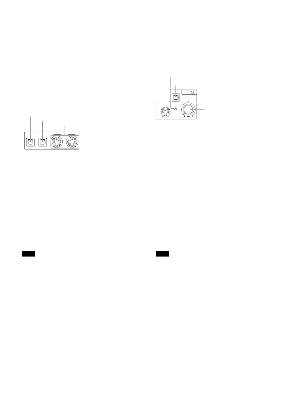
v IRIS/MASTER BLACK adjustment control block
r CUSTOM (custom volume) knob
Controls the function assigned to the knob on the <FRONT
PANEL 1> page in the CCU CONFIGURATION menu. Turning
the knob adjusts the assigned function.
See “VOLUME” on <FRONT PANEL 1> on page 29 and
“CUSTOM” on <FRONT PANEL 2> on page 30.
s White balance adjustment control block
ATW (auto tracing white balance) button
PRESET (white balance preset) button
WHITE (white balance manual adjustment) knobs
ATW PRESET
WHITE
• ATW (auto tracing white balance) button
The white balance is automatically adjusted in response to the
lighting conditions while this button is turned on and lit.
• PRESET (white balance preset) button
The white balance is automatically adjusted with a 3200K
color temperature preset value while this button is turned on
and lit.
• WHITE (white balance manual adjustment) knobs
Adjusts the white balance manually. The left knob adjusts the
R coefficient, and the right knob adjusts the B coefficient.
The adjustment can be set to relative or absolute value mode
on the <FRONT PANEL 1> page in the CCU
CONFIGURATION menu. The default value is relative value
mode.
See “R/B WHITE” on <FRONT PANEL 1> on page 29 and
“R/B WHITE” on <FRONT PANEL 2> on page 30.
MASTER BLACK (master black adjustment) knob
EXT (lens extender) indicator
AUTO (auto iris) button
IRIS/MB
MASTER BLACK
AUTO
EXT
ACTIVE
IRIS
IRIS/MB ACTIVE (iris/master black
active) indicator
IRIS (iris adjustment) knob
• MASTER BLACK (master black adjustment) knob
Adjusts the master black manually.
The adjustment can be set to relative or absolute value mode
on the <FRONT PANEL 1> page in the CCU
CONFIGURATION menu. The default value is relative value
mode.
See “M BLACK” on <FRONT PANEL 1> on page 29 and
“M BLACK” on <FRONT PANEL 2> on page 30.
• EXT (lens extender) indicator
Turns on to indicate that the lens extender is in-use on the
camera.
• AUTO (auto iris) button
Switches the lens auto iris adjustment function on/off (button
light turns on/off). The iris is automatically adjusted in
response to the input light level.
When the button is not lit, the iris is adjusted manually.
• IRIS/MB ACTIVE (iris/master black active) indicator
Indicates, when lit, that the iris and master black controls are
active (in panel active state set by the PANEL ACTIVE button).
When the indicator is lit, the iris and master black can be
adjusted from the CCU.
Note
When the ATW button is lit, the WHITE knobs are deactivated.
t AUTO WHITE/BLACK (white balance/black balance
auto adjustment) lever
Initiates the white balance or black balance auto adjustment
function.
WHITE automatically adjusts the white balance, and BLACK
automatically adjusts the black balance.
u BLACK/FLARE (black balance/flare balance manual
adjustment) knobs and indicator
Adjusts the black balance and flare balance manually. When
the indicator is not lit, the knobs adjust the black balance.
When the indicator is lit, the knobs adjust the flare balance.
The left knob adjusts the R coefficient, and the right knob
adjusts the B coefficient.
The indicator operating mode (on/off function) can be set on
the <FRONT PANEL 1> page in the CCU CONFIGURATION
menu.
The adjustment can be set to black balance or flare balance
adjustment in relative or absolute value mode on the <FRONT
Locations and Functions of Parts
12
Note
The indicator is not lit when the iris and master black controls in the
RCP-1000-series Remote Control Panel are active.
• IRIS (iris adjustment) knob
When the AUTO button is not lit: Adjusts the lens iris manually.
When the AUTO button is lit: Finely adjusts the auto adjusted
iris value.
The adjustment can be set to relative or absolute value mode
on the <FRONT PANEL 1> page in the CCU
CONFIGURATION menu. The default value is absolute value
mode.
See “IRIS” on <FRONT PANEL 1> on page 29 and “IRIS” on
<FRONT PANEL 2> on page 30.
 Loading...