

Page 1
Home Wireless
A/V System
2-674-819-01(1)
Operating Instructions
Manual de instrucciones
US
ES
HWS-AV10K
© 2006 Sony Corporation
Page 2

WARNING
To reduce the risk of fire or electric shock, do not expose this
apparatus to rain or moisture.
Note
You are cautioned that any changes or modifications not expressly approved in this manual
could void your authority to operate this equipment.
This transmitter must not be co-located or operated in conjunction with any other antenna or
transmitter.
This equipment complies with FCC radiation exposure limits set forth for uncontrolled
equipment and meets the FCC radio frequency (RF) Exposure Guidelines in Supplement C to
OET65. This equipment should be installed and operated with at least 20cm and more
between the radiator and person’s body (excluding extremities: hands, wrists, feet and legs).
Owner’s Record
The model and serial numbers are located on the bottom of both units. Record the serial
number in the space provided below. Refer to them whenever you call upon your Sony dealer
regarding this product.
Model number: HWS-AV10K
Transmitter: HWS-AV10T
Receiver: HWS-AV10R
Serial number
Transmitter: ___________________________
Receiver: ___________________________
US
2
Page 3

Table Of Contents
Features ........................................................................................................4
Preparing
Checking the package contents .................................................................5
Identifying parts and controls.....................................................................6
Transmitter .............................................................................................................. 6
Receiver................................................................................................................... 7
Preparing the transmitter ............................................................................8
Preparing the receiver .................................................................................9
Operating
Watching A/V contents ..............................................................................10
Improving reception...................................................................................11
To avoid the electromagnetic interference ............................................................ 11
Adjusting the dedicated antenna ........................................................................... 12
Installing the IR Blaster .............................................................................13
Others
Troubleshooting ......................................................................................... 14
Precautions.................................................................................................16
Specifications .............................................................................................17
US
US
3
Page 4
Features
Receiver
Transmitter
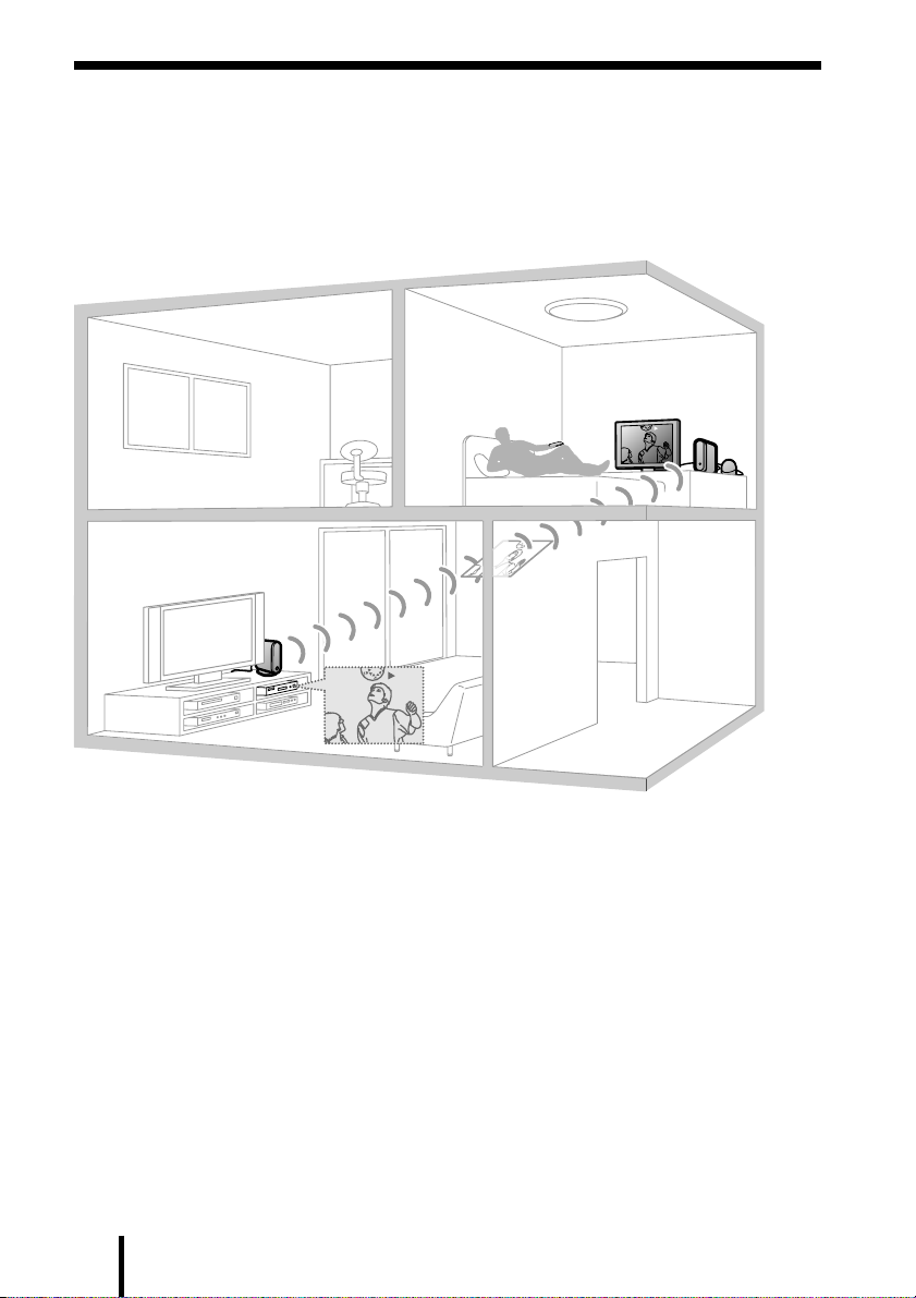
Enjoy wireless transmission of stereo A/V contents in virtually any room of your house.
Easily and wirelessly enjoy A/V contents playing in one room on a TV in another room. Just
plug the transmitter into the A/V equipment you want to watch and plug the receiver into the
TV in another room.
PLAY
Receiver
Receiver
Transmitter
Transmitter
PLAY
• Wireless system eliminates the need for cables running between rooms.
• Sony original 2.4 GHz wireless A/V transmission system.
•4 selectable transmission channels (frequencies) for optimum reception.
• Wireless remote control signal transmission, allowing remote control of transmitting A/V
equipment from another room (remote control not supplied).
• Remote control extender (IR Blaster) supplied to control A/V equipment in main room using
an existing remote control.
• Up to 100 ft. unobstructed signal reception (up to 60 ft. reception through most walls and
floors).
• Separate receiving dedicated antenna for excellent transmission.
* As with all wireless products, actual performance will vary depending on environment.
US
4
Page 5
Preparing
Checking the package contents
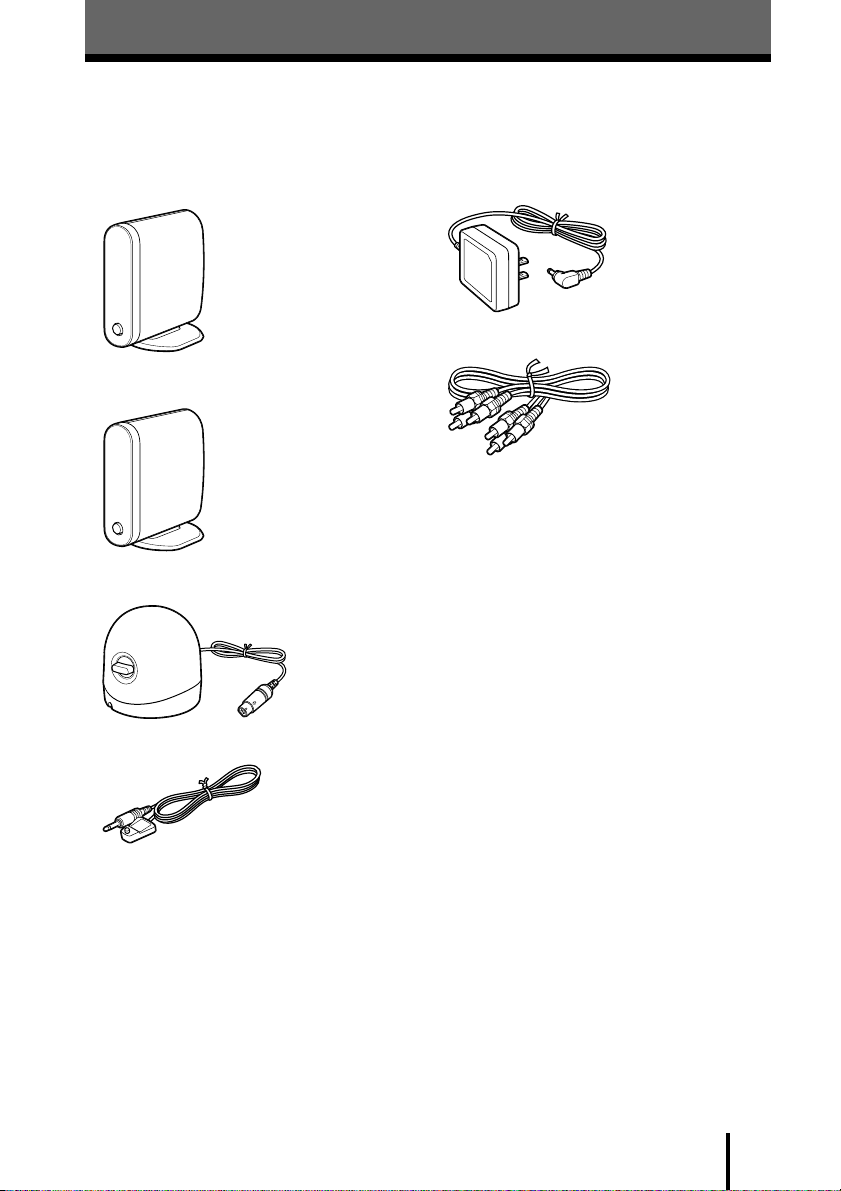
After unpacking, check that all the following items have been included:
• Transmitter: HWS-AV10T* (1)
• Receiver: HWS-AV10R* (1)
• Dedicated antenna (1)
• IR Blaster (1)
• AC power adaptor (2)
• A/V cable (2)
• Operating instructions (1)
• To enjoy clear images and sounds (1)
• Double sided seal (for IR Blaster) (1)
• Warranty card (1)
* The transmitter and receiver are the same shape.
Check the label on the bottom of both units for the
model name.
US
5
Page 6
Identifying parts and controls
CHANNEL
VIDEO IN
LEFT
AUDIO
IN
RIGHT
IR
EXTENDER
DC IN 6V
3
4
5
6
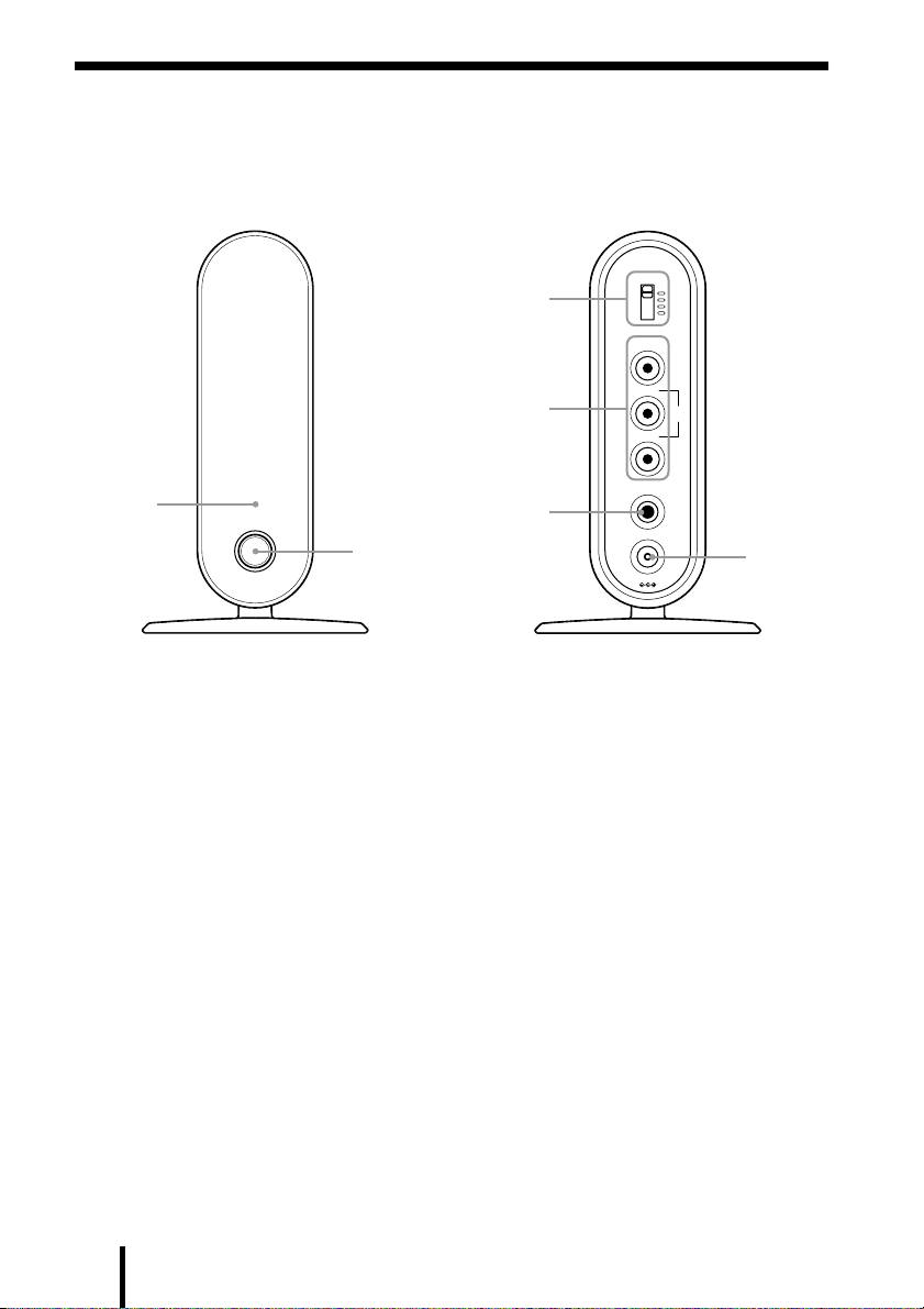
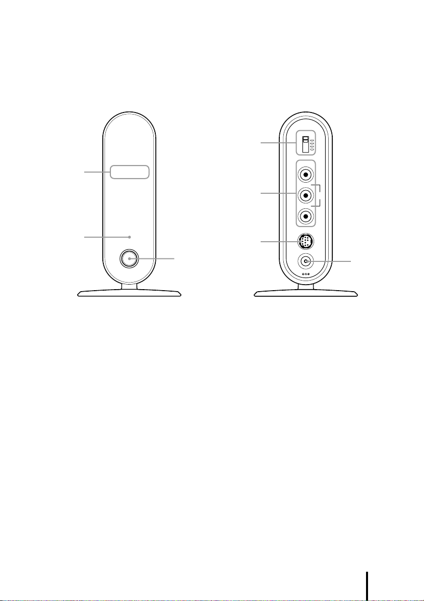
Transmitter
Front
1
2
Rear
1 Power indicator
Lights when the transmitter is turned on.
2 Power button
Turns the transmitter power on and off.
US
6
3 CHANNEL switch* (page 11)
Selects a desired channel (frequency) to
transmit.
4 VIDEO/AUDIO IN jacks (page 8)
Connects the A/V cables to A/V
equipment in main room.
5 IR EXTENDER jack (page 13)
Connects the IR Blaster (supplied).
Do not connect the other of supplied IR
Blaster.
6 DC IN 6V jack (page 8)
Connects the AC power adaptor
(supplied).
* Make sure to set the CHANNEL switch of the
transmitter and receiver to the same position.
Page 7
Receiver
CHANNEL
VIDEO OUT
LEFT
AUDIO
OUT
RIGHT
ANT
DC IN 6V
b
4
5
6
7
Front
1
2
1 Infrared receiver
Receives the signal from the remote
control.
Point and operate the remote control of
A/V equipment at here.
2 Power indicator
Lights when the receiver is turned on.
3 Power button
Turns the receiver power on and off.
Rear
3
4 CHANNEL switch* (page 11)
Selects a desired channel (frequency) to
receive.
5 VIDEO/AUDIO OUT jacks
(page 9)
Connects the A/V cables to your TV in
another room.
6 ANT jack (page 9)
Connects the dedicated antenna.
7 DC IN 6V jack (page 9)
Connects the AC power adaptor
(supplied).
* Make sure to set the CHANNEL switch of the
transmitter and receiver to the same position.
US
7
Page 8
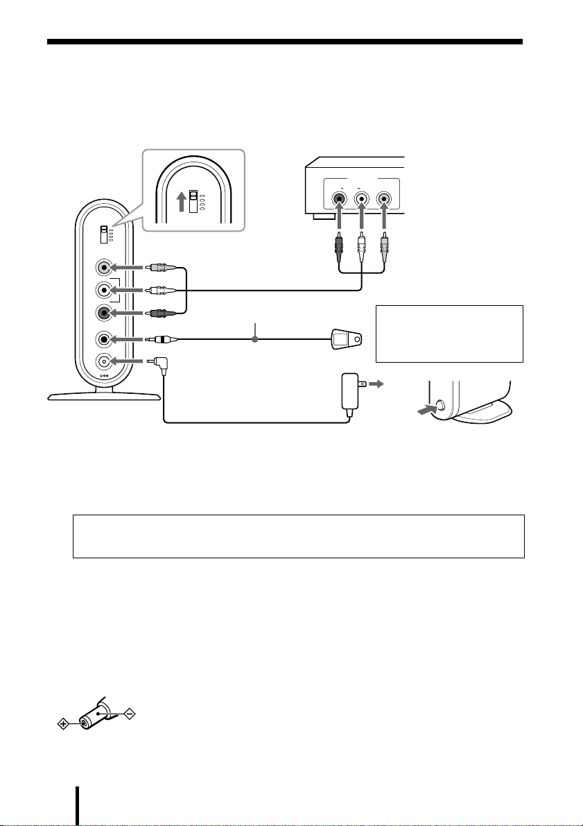
Preparing the transmitter
Connect the A/V equipment in the main room to the transmitter and then turn on the
transmitter. If you want to operate the A/V equipment connected with the transmitter from
another room, see “Installing the IR Blaster” (page 13) to set the IR Blaster.
A/V equipment
2
CHANNEL
CHANNEL
VIDEO IN
LEFT
RIGHT
IR
EXTENDER
DC IN 6V
AUDIO
OUT
IR Blaster (supplied)*
1
34
* Do not connect the other of supplied IR Blaster.
1 Connect the A/V equipment’s output jacks in the main room to the
transmitter’s VIDEO/AUDIO IN jacks with the A/V cable (supplied).
2 Set the CHANNEL switch to the top.
OUT PUT
R AUDIO L VIDEO
For details about
installing the IR Blaster,
see “Installing the IR
Blaster” (page 13).
5
Important
Make sure to set the CHANNEL switch of the transmitter and receiver to the same position.
3 Connect the AC power adaptor to the transmitter.
4 Connect the AC power adaptor to the wall outlet.
5 Press the POWER button on the front of the transmitter to turn it on.
The power indicator on the front of the transmitter lights green.
Notes
• Use only the recommended AC power adaptor manufactured by Sony. Polarity of the plugs of other
manufacturers may be different.
• If you connect a DVD player to the transmitter via a VCR, the VCR’s copy guard function may distort
or dim the DVD picture. In this case connect the DVD player directly to the VIDEO/AUDIO IN jack on
the transmitter.
US
8
Page 9
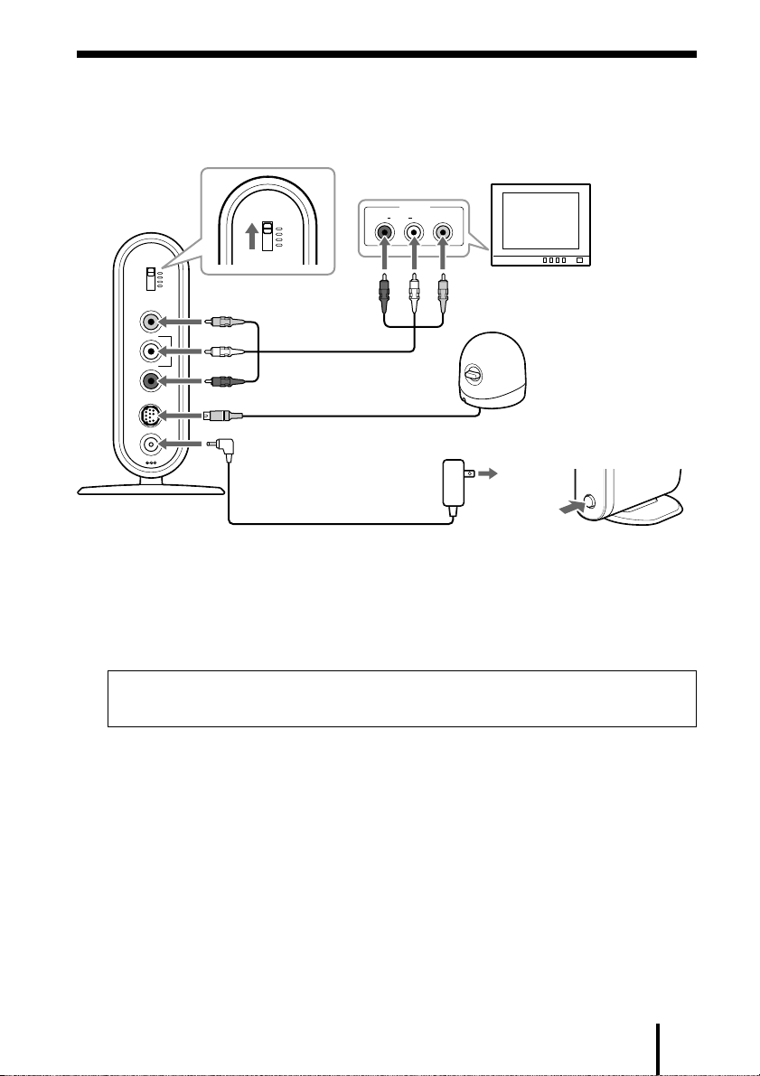
Preparing the receiver
Connect the TV in another room to the receiver and then turn on the receiver.
2
TV
INPUT
R AUDIO L VIDEO
5
CHANNEL
VIDEO OUT
LEFT
RIGHT
ANT
DC IN 6V
CHANNEL
AUDIO
OUT
b
3
1
4
6
1 Connect the TV’s external input jacks in the another room to the
receiver’s VIDEO/AUDIO OUT jacks with the other A/V cable
(supplied).
2 Set the CHANNEL switch to the top.
Important
Make sure to set the CHANNEL switch of the transmitter and receiver to the same position.
3 Connect the dedicated antenna to the ANT jack.
4 Connect the AC power adaptor to the receiver.
5 Connect the AC power adaptor to the wall outlet.
6 Press the POWER button on the front of the receiver to turn it on.
The power indicator on the front of the receiver lights green.
US
9
Page 10
Operating
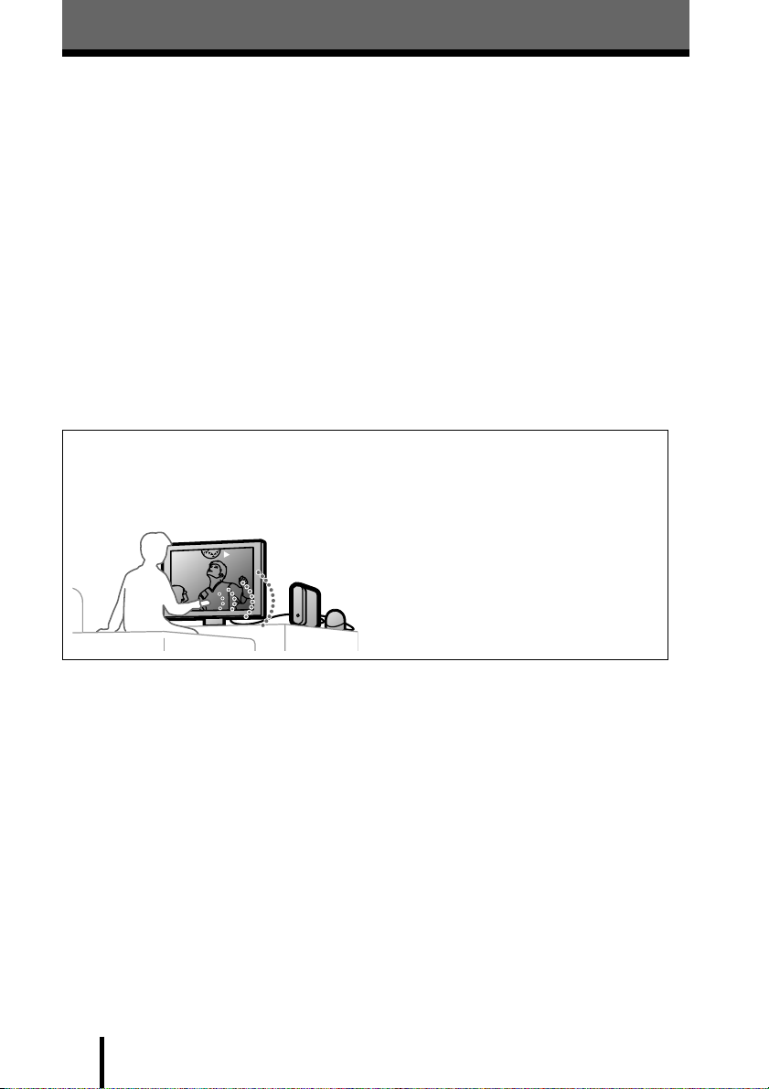
Watching A/V contents
You can enjoy images and sounds from A/V equipment connected to the transmitter in the
main room by setting the appropriate input. See also the TV’s instruction manual.
Before you operate the TV, make sure as following:
s Connected the transmitter to the A/V equipment and the receiver to the TV.
s Turned on the transmitter and receiver.
s Set the CHANNEL switch of transmitter and receiver to the same position.
1 Turn on the TV.
2 Set the TV to the appropriate input.
3 Play back the A/V equipment connected to the transmitter.
You can enjoy images and sounds received by the receiver.
Notes
• If the connected A/V equipment is not turned on, you cannot enjoy the image and sounds.
• If the image or sound is distorted, see “Improving reception” (page 11).
Information
If you operate the A/V equipment connected to the transmitter using the remote control,
see “Installing the IR Blaster” (page 13).
PLAY
10
US
Page 11
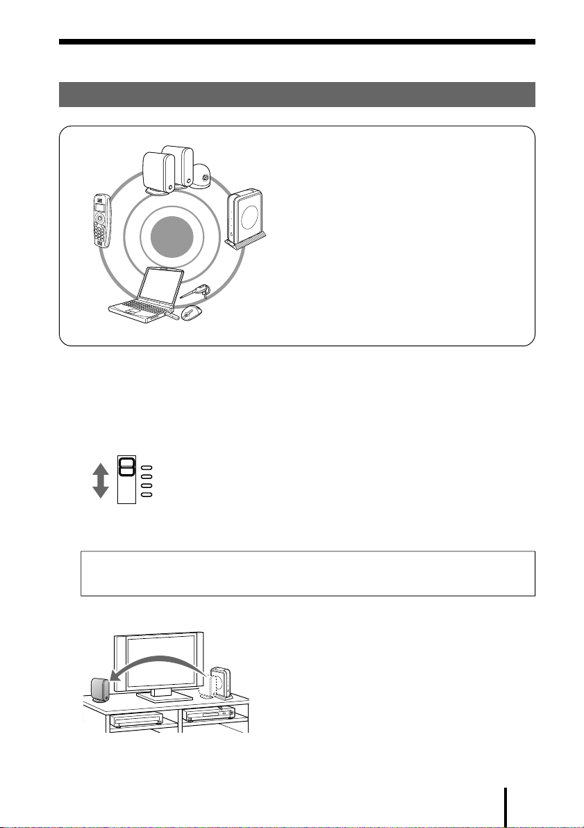
Improving reception
To avoid the electromagnetic interference
HWS-AV10K
This unit uses a 2.4 GHz frequency
range. This is the same frequency
range used by a cordless phone,
2.4 GHz range
2.4 GHz range
wireless equipment
wireless equipment
Cordless phone Wireless LAN
Cordless phone
Wireless LAN
system
system
wireless LAN, Bluetooth equipment,
microwave oven or other wireless
equipment. If you use this unit
together such equipment, malfunction
may result.
Bluetooth
R
equipment
If this unit or other equipment does not work correctly
Try one or both of the following procedures.
1 Change the frequency (CHANNEL switch) to another frequency.
CHANNEL
Channel 1 : 2.415 GHz
Channel 2 : 2.429 GHz
Channel 3 : 2.443 GHz
Channel 4 : 2.457 GHz
You can avoid conflicts between this unit and other equipment by changing the CHANNEL
switch on the rear of this unit. See the table at above for the frequency settings.
Important
Make sure to set the CHANNEL switch of the transmitter and receiver to the same position.
2 Move this unit away from other equipment.
When you are using this unit close to other equipment, electromagnetic interference may
occur. Move this unit away from other equipment.
11
US
Page 12

Adjusting the dedicated antenna
If the image is distorted, try the following procedures.
1 Rotate the dedicated antenna horizontally for optimum reception.
2 Adjust the dedicated antenna by using the antenna adjuster knob.
Antenna adjuster knob
3 Repeat step 1 and 2, and set the dedicated antenna where a clear
image is achieved.
Tips
• The antenna adjuster knob has a “v”mark to show the reception direction, which can be adjusted for
optimum sensitivity.
Antenna adjuster knob
• You can set the dedicated antenna by adjusting the cable along the groove on the bottom of the
dedicated antenna.
Bottom of the dedicated antenna
US
12
Page 13

Installing the IR Blaster
You can operate the A/V equipment connected to the transmitter using the remote control in
another room.
Another room A/V equipment's room
PLAY
Set the IR Blaster by the following procedure.
Control signal
1 Put the supplied double sided seal on the IR Blaster.
Do not remove the opposite face of the double sided seal yet. You can also use a
store-bought double sided seal.
Double sided seal
2 Connect the IR Blaster to the IR EXTENDER jack on the rear of the
transmitter.
Do not connect the other of supplied IR Blaster.
3 Position the IR Blaster above the infrared receiver on the A/V
equipment.
To locate the infrared receiver, see the instruction manual for the connected A/V
equipment. Make sure to place the IR Blaster just above the infrared receiver.
PLAY
A/V equipment
Infrared emitter
Infrared receiver
4 Perform the operation test.
Point and operate the remote control of A/V equipment at the receiver’s infrared receiver,
and check the performance of the connected A/V equipment correctly.
5 Fix the IR Blaster.
After performing the operation test on the connected A/V equipment, remove the opposite
face of the double sided seal, and then fix the IR Blaster in the installation in step 3.
Notes
• Some A/V equipment may not operate correctly, depending on the installation location. Install the IR
Blaster and A/V equipment’s infrared receiver as close as possible.
• If other A/V equipment is nearby the transmitter, accidental wrong operation of this A/V equipment may
occur due to the location of the IR Blaster. In this case, change the installation location of the IR Blaster.
• If you place the transmitter too close to the receiver, the signal may be looped from the receiver back to
the transmitter. In this case, place the receiver further apart from the transmitter.
13
US
Page 14

Others
Troubleshooting
There is no picture or sound on the TV.
The unit does not turn on.
The unit does not connect
to A/V equipment
correctly, or there is no
A/V signal from the A/V
equipment.
The transmitter’s
frequency is different
from the receiver’s.
No signal reaches the
receiver.
Electromagnetic
interference occurs.
The TV is not set to the
appropriate input.
c Make sure to turn on the transmitter and receiver.
c Make sure to connect the transmitter to the AC power adaptor,
and then to a wall outlet.
c Make sure to connect the receiver to the AC power adaptor, and
then to a wall outlet.
c Make sure to connect the transmitter to the A/V equipment.
c Make sure to connect the receiver to the TV, and the receiver to
the dedicated antenna.
c Turn on the A/V equipment connected to the transmitter and
play back.
c Make sure to set the CHANNEL switch of the transmitter and
receiver to the same position.
c Adjust the direction of the dedicated antenna (page 12).
c Set the transmitter closer to the dedicated antenna.
c If there are any obstacles (especially metallic) between the
transmitter and the receiver, remove them.
c Reorient the dedicated antenna to minimize the problem (page
12).
c When you are using a microwave oven near the dedicated
antenna, electromagnetic interference occurs in the unit, but
stops if you stop using the microwave oven.
c When you are using a cordless phone, a wireless LAN,
Bluetooth equipment such as same frequency (2.4 GHz)
wireless equipment as the unit near the dedicated antenna,
change the CHANNEL switch (frequency) to another frequency
to avoid interference, or set the unit away from the interfering
equipment.
c Set the TV to the appropriate input.
14
US
Page 15

There is a noise on the image or sound.
The signal from the
transmitter is weak.
The unit is influenced by
other electromagnetic
radiation.
You cannot use a wireless LAN when you started using the unit.
This malfunction occurs
as a result of the unit and
wireless LAN’s frequency
being the same.
c Reorient the dedicated antenna (page 12).
c Set the transmitter closer to the dedicated antenna.
c If there are any obstacles (especially metallic) between the
transmitter and the receiver, remove them.
If you set the transmitter or the receiver (the dedicated antenna)
in a cabinet, relocate out of cabinet.
c Reorient the dedicated antenna to minimize the problem (page
12).
c When you are using a microwave oven near the dedicated
antenna, electromagnetic interference occurs in the unit, but
stops if you stop using the microwave oven.
c When you are using a cordless phone, a wireless LAN,
Bluetooth equipment such as same frequency (2.4 GHz)
wireless equipment as the unit near the dedicated antenna,
change the CHANNEL switch (frequency) to another frequency
to avoid interference, or set the unit away from the interfering
equipment.
c Change to another frequency so as not to influence the wireless
LAN.
c Set the transmitter away from the equipment using the wireless
LAN.
You cannot operate the remote control.
The remote control signal
does not get to the
receiver’s infrared
receiver.
The signal from the
transmitter (IR Blaster)
does not reach the infrared
receiver of the A/V
equipment connected to
the transmitter.
c Point and operate the remote control from a position that faces
the receiver.
c If there are any obstacles between the receiver and the remote
control, remove them.
c Make sure to connect the IR Blaster to the transmitter correctly.
c Set the infrared position (forefront) of the IR Blaster to the
infrared receiver position of the A/V equipment connected to
the transmitter.
15
US
Page 16

Precautions
• Operate the unit on the power sources specified in “Specifications”.
• The nameplate indicating voltage, etc. is located on the bottom of the unit.
• To disconnect the power cord (mains lead), pull it out by the plug, not the cord.
• Disconnect the AC power adaptor from the wall outlet when the unit is not to be used for a
long period of time.
• Do not place the unit on surfaces (rugs, blankets, etc.) or near materials (curtains, draperies)
that block the ventilation holes.
• Should any liquid or solid object fall into the unit, unplug the unit and have it checked by
qualified personnel before operating it further.
• To clean the casing, use a soft cloth dampened with a mild detergent solution.
• Be sure to bring the transmitter, receiver and dedicated antenna to the Sony dealer when
requiring repair work.
If you have any questions or problems concerning the system that are not covered in this
manual, please consult your nearest Sony dealer.
16
US
Page 17

Specifications
General
Model name: HWS-AV10K
Transmission frequency:
A/V signal Channel 1 : 2.415 GHz
Channel 2 : 2.429 GHz
Channel 3 : 2.443 GHz
Channel 4 : 2.457 GHz
Control signal 433.92 MHz
Max. communication range: Line of sight approx.100 ft. (30 m)
Operating temperature: 0°C to 40°C (32°F to 104°F)
Supplied accessories:
AC power adaptor (DC 6 V, 800 mA) (2), A/V cable (approx. 39.4 inches/1 m,
V/L/R y V/L/R) (2), IR Blaster (1), Double sided seal (1), Operating instructions
(1), To enjoy clear images and sounds (1), Warranty card (1)
Transmitter: HWS-AV10T
Video input: Impedance: 75 Ω
Level: 1 Vp-p
Audio input: Impedance: 81 kΩ
Level: 0.5 Vrms
Power consumption: Less than 240 mA
Power requirement: DC 6 V (supplied AC power adaptor)
Input terminal: Pin jack (Video, Audio L/R)
Output terminal: ø 3.5 mm monaural mini jack (IR Blaster)
Dimensions (w/h/d): approx. 2.7 × 4.9 × 4.3 inches (approx. 68 × 124 × 110 mm)
Mass: approx. 6.7 oz (186 g)
Receiver: HWS-AV10R
Video output: Level: 1 Vp-p
Audio output: Level: 0.5 Vrms
Frequency response: 100 Hz - 20 kHz
Power consumption: Less than 260 mA
Power requirement: DC 6 V (supplied AC power adaptor)
Input terminal: 10-pin mini DIN jack (Dedicated antenna)
Output terminal: Pin jack (Video, Audio L/R)
Dimensions (w/h/d):
Main unit: approx. 2.7 × 4.9 × 4.3 inches (approx. 68 × 124 × 110 mm)
Dedicated antenna: approx. 3.4 × 3.2 × 3.2 inches (approx. 86 × 82 × 82 mm)
(Cable length: approx. 39.4 inches/1 m)
Mass:
Main unit: approx. 5.8 oz (approx. 165 g)
Dedicated antenna: approx. 4.7 oz (approx. 133 g)
Design and specifications are subject to change without notice.
17
US
Page 18

ADVERTENCIA
Para reducir el riesgo de incendios o electrocución, no exponga el aparato a la
lluvia ni a la humedad.
Nota
Tenga en cuenta que cualquier cambio o modificación no expresamente aprobado en este manual puede
anular su autoridad para utilizar este equipo.
El transmisor no debe colocarse ni utilizarse junto con ninguna otra antena o transmisor.
Este equipo cumple con los límites de exposición a la radiación de la FCC establecida para
equipos no controlados y con las directrices de exposición a radiofrecuencia (RF) de la FCC
que figuran en el suplemento C de la OET65. Este equipo debe instalarse y utilizarse con una
separación mínima de 20 cm o superior entre el radiador y el cuerpo de la persona (excluidas
las extremidades: manos, muñecas, pies y piernas).
ES
2
Page 19

Tabla de contenido
Características ............................................................................................. 4
Preparación
Comprobación del contenido del paquete ................................................ 5
Identificación de piezas y controles...........................................................6
Transmisor ............................................................................................................... 6
Receptor .................................................................................................................. 7
Preparación del transmisor.........................................................................8
Preparación del receptor .............................................................................9
Funcionamiento
Visualización de contenidos de A/V .........................................................10
Mejora de la recepción .............................................................................. 11
Para evitar interferencias electromagnéticas ......................................................... 11
Ajuste de la antena específica ............................................................................... 12
Instalación del IR Blaster .......................................................................... 13
ES
Otros
Solución de problemas..............................................................................14
Precauciones ..............................................................................................16
Especificaciones ........................................................................................17
3
ES
Page 20

Características
Rece
pto
Transmisoso
Disfrute de la transmisión inalámbrica de contenido de A/V estéreo en casi cualquier
habitación de la casa.
Disfrute del contenido de A/V que se está reproduciendo en una habitación, en un televisor de
otra habitación de manera sencilla y sin cables. Simplemente enchufe el transmisor en el
equipo de A/V en el que desee visualizar los contenidos y enchufe el receptor en el televisor de
la otra habitación.
PLAY
Rece
pto
Receptor
r
Transmi
Transmisor
r
PLAY
• El sistema inalámbrico elimina la necesidad de pasar cables de una habitación a otra.
• Sistema de transmisión de A/V inalámbrico de 2,4 GHz original Sony.
• Cuatro canales de transmisión seleccionables (frecuencias) para conseguir una recepción
óptima.
• La transmisión de señales de control remoto inalámbrico permiten el control remoto del
equipo transmisor de señales de A/V desde otra habitación (el control remoto no viene
suministrado).
• Se suministra un amplificador para el control remoto (IR Blaster) para controlar los equipos
de A/V situados en la habitación principal mediante un control remoto del que ya disponga.
• Alcance de la recepción de la señal sin obstáculos de hasta 30 metros (alcance de la
recepción de hasta 18 metros a través de la mayoría de las paredes y suelos).
• Antena específica para la recepción independiente para obtener una excelente transmisión.
* Al igual que con todos los productos inalámbricos, el rendimiento real variará en función del entorno.
ES
4
Page 21

Preparación
Comprobación del contenido del paquete
Después de abrir el paquete, compruebe que incluye todos los siguientes elementos:
• Transmisor: HWS-AV10T* (1)
• Receptor: HWS-AV10R* (1)
• Antena específica (1)
• IR Blaster (1)
• Adaptador de alimentación de ca (2)
• Cable de A/V (2)
• Manual de instrucciones (1)
• Para disfrutar de imágenes y sonidos nítidos
(1)
• Sello de dos caras (para el IR Blaster) (1)
• Tarjeta de garantía (1)
* El transmisor y el receptor tienen la misma forma.
Compruebe la etiqueta situada en la parte inferior
de ambas unidades para obtener el nombre del
modelo.
ES
5
Page 22

Identificación de piezas y controles
CHANNEL
VIDEO IN
LEFT
AUDIO
IN
RIGHT
IR
EXTENDER
DC IN 6V
3
4
5
6
Transmisor
Parte frontal
1
2
Parte posterior
1 Receptor de infrarrojos
Se ilumina al encender el transmisor.
2 Botón de encendido
Activa y desactiva la alimentación del
transmisor.
ES
6
3 Interruptor CHANNEL* (página
11)
Selecciona el canal (frecuencia) a través
del que desee realizar la transmisión.
4 Tomas VIDEO/AUDIO IN
(página 8)
Conecta los cables de A/V al equipo de
A/V de la habitación principal.
5 Toma IR EXTENDER (página
13)
Conecta el IR Blaster (suministrado).
No conecte otros equipos distintos del IR
Blaster suministrado.
6 Toma DC IN 6V (página 8)
Conecta el adaptador de alimentación de
ca (suministrado).
* Asegúrese de ajustar el interruptor CHANNEL
del transmisor y del receptor en la misma
posición.
Page 23

Receptor
CHANNEL
VIDEO OUT
LEFT
AUDIO
OUT
RIGHT
ANT
DC IN 6V
b
4
5
6
7
Parte frontal
1
2
3
1 Receptor por infrarrojos
Recibe la señal del control remoto.
Oriente el control remoto del equipo de A/
V hacia este punto para utilizarlo.
2 Indicador de alimentación
Se ilumina al encender el receptor.
3 Botón de encendido
Activa y desactiva la alimentación del
receptor.
Parte posterior
4 Interruptor CHANNEL*
(página 11)
Selecciona el canal (frecuencia) que
desea recibir.
5 Tomas VIDEO/AUDIO OUT
(página 9)
Conectan los cables de A/V al televisor
situado en otra habitación.
6 Toma ANT (página 9)
Conecta la antena específica.
7 Toma DC IN 6V (página 9)
Conecta el adaptador de alimentación de
ca (suministrado).
* Asegúrese de ajustar el interruptor CHANNEL
del transmisor y del receptor en la misma
posición.
ES
7
Page 24

Preparación del transmisor
Conecte el equipo de A/V de la habitación principal al transmisor y, a continuación, encienda
el transmisor. Si desea utilizar el equipo de A/V conectado mediante el transmisor situado en
la otra habitación, consulte “Instalación del IR Blaster” (página 13) para ajustar el IR Blaster.
Equipo de A/V
2
CHANNEL
CHANNEL
VIDEO IN
LEFT
RIGHT
IR
EXTENDER
DC IN 6V
AUDIO
OUT
IR Blaster (suministrado)*
1
34
* No conecte otros equipos distintos del IR Blaster suministrado.
1 Conecte las tomas de salida de A/V del equipo situado en la
habitación principal a las tomas VIDEO/AUDIO IN del transmisor
mediante el cable de A/V (suministrado).
2 Ajuste el interruptor CHANNEL en la posición superior.
OUT PUT
R AUDIO L VIDEO
Para obtener información
acerca de la instalación del IR
Blaster, consulte “Instalación
del IR Blaster” (página 13).
5
Importante
Asegúrese de ajustar el interruptor CHANNEL del transmisor y del receptor en la
misma posición.
3 Conecte el adaptador de alimentación de ca al transmisor.
4 Conecte el adaptador de alimentación de ca a la toma de pared.
5 Presione el botón POWER situado en la parte frontal del transmisor
para encenderlo.
El indicador de alimentación situado en la parte frontal del transmisor se iluminará en
verde.
Notas
• Utilice únicamente el adaptador de alimentación de ca recomendado fabricado por
Sony. Es posible que la polaridad de las clavijas de otros fabricantes sea diferente.
• Si conecta un reproductor de DVD al transmisor a través de una videograbadora, es posible que la
función de protección de copia de ésta distorsione o atenúe la imagen del DVD. En tal caso, conecte el
reproductor de DVD directamente a la toma VIDEO/AUDIO IN del transmisor.
ES
8
Page 25

Preparación del receptor
Conecte el televisor situado en otra habitación al receptor y, a continuación, encienda el
receptor.
Televisor
2
INPUT
R AUDIO L VIDEO
CHANNEL
VIDEO OUT
LEFT
RIGHT
CHANNEL
AUDIO
OUT
1
ANT
b
DC IN 6V
4
3
5
6
1 Conecte las tomas de entrada externas del televisor situado en otra
habitación a las tomas VIDEO/AUDIO OUT del receptor mediante el
otro cable de A/V (suministrado).
2 Ajuste el interruptor CHANNEL en la posición superior.
Importante
Asegúrese de ajustar el interruptor CHANNEL del transmisor y del receptor en la
misma posición.
3 Conecte la antena específica a la toma ANT.
4 Conecte el adaptador de alimentación de ca al receptor.
5 Conecte el adaptador de alimentación de ca a la toma de pared.
6 Presione el botón POWER situado en la parte frontal del receptor
para encenderlo.
El indicador de alimentación situado en la parte frontal del receptor se iluminará en verde.
ES
9
Page 26

Funcionamiento
Visualización de contenidos de A/V
Es posible disfrutar de imágenes y sonido del equipo de A/V conectado al transmisor situado
en la habitación principal mediante el ajuste de la entrada adecuada. Consulte asimismo el
manual de instrucciones del televisor.
Antes de utilizar el televisor, asegúrese de lo siguiente:
s Ha conectado el transmisor al equipo de A/V y el receptor al televisor.
s Ha encendido el transmisor y el receptor.
s Ha ajustado el interruptor CHANNEL del transmisor y del receptor en la misma posición.
1 Encienda el televisor.
2 Ajuste el televisor en la entrada adecuada.
3 Inicie la reproducción en el equipo de A/V conectado al transmisor.
Es posible disfrutar de las imágenes y el sonido recibidos por el receptor.
Notas
• Si el equipo de A/V conectado no está encendido, no podrá disfrutar de la imagen y el sonido.
• Si se distorsiona la imagen o el sonido, consulte “Mejora de la recepción” (página 11).
Información
Si usa el control remoto para utilizar el equipo de A/V conectado al transmisor, consulte
el apartado "Instalación del IR Blaster" (página 13).
10
PLAY
ES
Page 27

Mejora de la recepción
Para evitar interferencias electromagnéticas
HWS-AV10K
Esta unidad utiliza un rango de
frecuencias de 2,4 GHz.
Se trata del mismo rango de
frecuencias que utilizan los teléfonos
inalámbricos, las redes LAN
inalámbricas, los equipos Bluetooth,
los hornos microondas y otros equipos
inalámbricos. Si se utiliza esta unidad
Teléfono
Teléfono
inalámbrico
inalámbrico
Equipo inalámbrico
Equipo inalámbrico
con un rango de
con un rango de
frecuencias de 2,4 GHz
frecuencias de 2,4 GHz
Sistema LAN
Sistema LAN
inalámbrico
inalámbrico
junto con dichos equipos, es posible
que se produzcan fallos en el
Equipo Bluetooth
R
funcionamiento.
Si esta unidad o bien otro equipo no funcionan correctamente
Intente llevar a cabo uno de los siguientes procedimientos o ambos.
1 Cambie la frecuencia (interruptor CHANNEL) a otra distinta.
CHANNEL
CANAL 1: 2,415 GHz
CANAL 2: 2,429 GHz
CANAL 3: 2,443 GHz
CANAL 4: 2,457 GHz
Es posible evitar interferencias entre la unidad y otros equipos al cambiar la posición del
interruptor CHANNEL de la parte posterior de la unidad. Consulte la tabla anterior para
ver los ajustes de las frecuencias.
Importante
Asegúrese de ajustar el interruptor CHANNEL del transmisor y del receptor en la misma
posición.
2 Move this unit away from other equipment.
Si se utiliza esta unidad cerca de otros equipos, es posible que se produzcan interferencias
electromagnéticas. Aleje la unidad de otros equipos.
11
ES
Page 28

Ajuste de la antena específica
Si la imagen se distorsiona, realice los siguientes procedimientos.
1 Gire la antena específica horizontalmente para obtener una
recepción óptima.
2 Ajuste la antena específica mediante el mando de Mando de ajuste
de la antena
Mando de ajuste de la antena
3 Repita los pasos 1 y 2 y ajuste la antena específica en una posición
en la que se reciban imágenes nítidas.
Sugerencias
• El mando de ajuste de la antena presenta la marca “v” para mostrar la dirección de la recepción, que
puede ajustarse para lograr una sensibilidad óptima.
Mando de ajuste de la antena
• Es posible ajustar la antena específica mediante el ajuste del cable en la ranura situada en la parte
inferior de la misma.
Parte inferior de la antena específica
ES
12
Page 29

Instalación del IR Blaster
Es posible usar el control remoto desde otra habitación para utilizar el equipo de A/V
conectado al transmisor.
Habitación del equipo de A/V Habitación del equipo de A/V
PLAY
Siga el procedimiento indicado a continuación para conectar el IR Blaster.
Señal de control
1 Coloque el sello de dos caras suministrado en el IR Blaster.
No extraiga todavía la cara opuesta del
sello de dos caras. También es posible
utilizar un sello de dos caras adquirido por
separado.
2 Enchufe el IR Blaster en la toma IR EXTENDER situada en la parte
posterior del transmisor.
No conecte otros equipos distintos del IR Blaster suministrado.
3 Coloque el IR Blaster por encima del receptor de infrarrojos del
equipo de A/V.
Para ubicar el receptor de infrarrojos,
consulte el manual de instrucciones del
equipo de A/V conectado. Asegúrese de
colocar el IR Blaster justo por encima
del receptor de infrarrojos.
PLAY
Sello de dos caras
Equipo de A/V
Emisor de infrarrojos
Receptor de infrarrojos
4 Efectúe la prueba de funcionamiento.
Oriente el control remoto del equipo de A/V hacia el receptor de infrarrojos del receptor y
compruebe que el equipo de A/V conectado funcione correctamente.
5 Fije el IR Blaster.
Después de efectuar la prueba de funcionamiento en el equipo de A/V conectado, extraiga
la cara opuesta del sello de dos caras y, a continuación, efectúe el paso 3 de la instalación
para fijar el IR Blaster.
Notas
• Es posible que algunos equipos de A/V no funcionen correctamente en función del lugar de instalación.
Instale el IR Blaster y el receptor de infrarrojos tan cerca como sea posible.
• Si hay otro equipo de A/V cerca del transmisor, es posible que se produzca un funcionamiento
incorrecto accidental del mismo debido a la ubicación del IR Blaster. En tal caso, cambie el lugar de
instalación del IR Blaster.
• Si coloca el transmisor demasiado cerca del receptor, es posible que la señal vuelva desde el receptor de
nuevo hasta el transmisor. En tal caso, aleje el receptor del transmisor.
13
ES
Page 30

Otros
Solución de problemas
No se escucha el sonido ni se ve la imagen en el televisor.
La unidad no se enciende.
La unidad no se conecta al
equipo de A/V
correctamente o no existe
señal de A/V proveniente
del equipo de A/V.
La frecuencia del
transmisor es diferente de
la del receptor.
No llega ninguna señal al
receptor.
Se producen interferencias
electromagnéticas.
El televisor no está
ajustado en la entrada
adecuada.
c Asegúrese de encender el transmisor y el receptor.
c Asegúrese de conectar el transmisor al adaptador de
alimentación de ca y, a continuación, a una toma de pared.
c Asegúrese de conectar el receptor al adaptador de alimentación
de ca y, a continuación, a una toma de pared.
c Asegúrese de conectar el transmisor al equipo de A/V.
c Asegúrese de conectar el receptor al televisor y el receptor a la
antena específica.
c Encienda el equipo de A/V conectado al transmisor e inicie la
reproducción.
c Asegúrese de ajustar el interruptor CHANNEL del transmisor y
del receptor en la misma posición.
c Ajuste la orientación de la antena específica (página 12).
c Coloque el transmisor más cerca de la antena específica.
c Si existe algún obstáculo (especialmente si es metálico) entre el
transmisor y el receptor, elimínelo.
c Vuelva a orientar la antena específica para minimizar el
problema (página 12).
c Si utiliza un horno microondas cerca de la antena específica, se
producirán interferencias electromagnéticas en la unidad, pero
dejarán de producirse si deja de utilizar dicho horno
microondas.
c Si utiliza un teléfono inalámbrico, una red LAN inalámbrica,
equipos Bluetooth o equipos inalámbricos que utilicen la misma
frecuencia (2,4 GHz) que la unidad cerca de la antena
específica, cambie el interruptor CHANNEL (frecuencia) a otra
frecuencia para evitar interferencias o aleje la unidad del equipo
que cause dichas interferencias.
c Ajuste el televisor en la entrada adecuada.
14
ES
Page 31

Se produce ruido en la imagen o el sonido.
La señal proveniente del
transmisor es débil.
La unidad está afectada
por otras radiaciones
electromagnéticas.
No es posible utilizar una red LAN inalámbrica una vez haya empezado a utilizar la
unidad.
TEste fallo de
funcionamiento se
produce debido a que la
frecuencia de la red LAN
inalámbrica y la de la
unidad es la misma.
c Vuelva a orientar la antena específica (página 12).
c Coloque el transmisor más cerca de la antena específica.
c Si existe algún obstáculo (especialmente si es metálico) entre el
transmisor y el receptor, elimínelo.
Si coloca el transmisor o el receptor (la antena específica) en un
armario, vuelva a colocarlos fuera del mismo.
c Vuelva a orientar la antena específica para minimizar el
problema (página 12).
c Si utiliza un horno microondas cerca de la antena específica, se
producirán interferencias electromagnéticas en la unidad, que
dejarán de producirse si deja de utilizar dicho horno
microondas.
c Si utiliza un teléfono inalámbrico, una red LAN inalámbrica,
equipos Bluetooth o equipos inalámbricos que utilicen la misma
frecuencia (2,4 GHz) que la unidad cerca de la antena
específica, cambie el interruptor CHANNEL (frecuencia) a otra
frecuencia para evitar interferencias o aleje la unidad del equipo
que cause dichas interferencias.
c Cambie la frecuencia de modo que no interfiera con la red LAN
inalámbrica.
c Aleje el transmisor del equipo que esté utilizando la red LAN
inalámbrica.
No es posible utilizar el control remoto.
La señal del control
remoto no llega al
receptor de infrarrojos del
receptor.
La señal del transmisor
(IR Blaster) no llega al
receptor de infrarrojos del
equipo de A/V conectado
al transmisor.
c Utilice el control remoto desde una ubicación situada frente al
receptor.
c Si existe algún obstáculo entre el receptor y el control remoto,
elimínelo.
c Asegúrese de conectar el IR Blaster al transmisor
correctamente.
c Ajuste la posición de los infrarrojos (parte frontal) del IR
Blaster en la posición del receptor de infrarrojos del equipo de
A/V conectado al transmisor.
15
ES
Page 32

Precauciones
• Utilice la unidad con las fuentes de alimentación especificadas en “Especificaciones”.
• La placa de características que indica el voltaje, etc. está ubicada en la parte inferior de la
unidad.
• Para desconectar el cable de alimentación (cable de corriente), tire siempre del enchufe,
nunca del cable.
• Desconecte el adaptador de alimentación de ca de la toma de pared si no va a utilizar la
unidad durante un largo período de tiempo.
• No instale la unidad sobre superficies como alfombras, mantas, etc., ni cerca de telas
(cortinas o tejidos) que puedan bloquear los orificios de ventilación.
• Si se introduce algún objeto sólido o líquido en la unidad, desenchúfela y haga que sea
revisada por personal especializado antes de volver a utilizarla.
• Para limpiar la unidad, utilice un paño suave humedecido con una solución de detergente
poco concentrada.
• Asegúrese de llevar el transmisor, el receptor y la antena específica al distribuidor Sony
cuando necesite realizar trabajos de reparación.
Si tiene alguna pregunta o problema relacionado con el sistema que no se aborde en este
manual, póngase en contacto con el distribuidor Sony más cercano.
16
ES
Page 33

Especificaciones
General
Nombre del modelo: HWS-AV10K
Frecuencia de transmisión:
Señal de A/V CANAL 1: 2,415 GHz
CANAL 2: 2,429 GHz
CANAL 3: 2,443 GHz
CANAL 4: 2,457 GHz
Señal de control 433,92 MHz
Rango de comunicación máximo: Aprox. 30 m en línea recta
Temperatura de funcionamiento: De 0ºC a 40ºC
Accesorios suministrados:
Adaptador de alimentación de ca (6 V de cc, 800 mA) (2), cable de A/V
(aprox. 1 m V/L/R y V/L/R) (2), IR Blaster (1), sello de dos caras (1), manual de
instrucciones (1), para disfrutar de imágenes y sonidos nítidos (1),
tarjeta de garantía (1)
Transmisor: HWS-AV10T
Entrada de video: Impedancia: 75 Ω
Nivel: 1 Vp-p
Entrada de audio: Impedancia: 81 kΩ
Nivel: 0,5 Vrms
Consumo de energía: Inferior a 240 mA
Requisitos de alimentación: 6 V de cc (adaptador de alimentación de ca suministrado)
Terminal de entrada: Toma de pines (Video, Audio L/R)
Terminal de salida: Minitoma monoaural de ø 3,5 mm (IR Blaster)
Dimensiones (an/al/prf): Aprox. 68 × 124 × 110 mm
Peso: Aprox. 186 g
Receptor: HWS-AV10R
Salida de video: Nivel: 1 Vp-p
Salida de audio: Nivel: 0,5 Vrms
Respuesta de frecuencia: De 100 Hz a 20 kHz
Consumo de energía: Inferior a 260 mA
Requisitos de alimentación: 6 V de cc (adaptador de alimentación de ca suministrado)
Terminal de entrada: Minitoma DIN de 10 pines (antena específica)
Terminal de salida: Toma de pines (Video, Audio L/R)
Dimensiones (an/al/prf):
Unidad principal: Aprox. 68 × 124 × 110 mm
Antena específica: Aprox. 86 × 82 × 82 mm
(longitud del cable: aprox. 1 m)
Peso:
Unidad principal: Aprox. 165 g
Antena específica: Aprox. 133 g
El diseño y las especificaciones están sujetos a cambios sin previo aviso.
17
ES
Page 34

18
ES
Page 35

19
ES
Page 36

Printed in China
 Loading...