

Sony HFBK-XG1 Operation Manual
XGA INTERFACE BOARD
HFBK-XG1
電気製品は、安全のための注意事項を守らないと、
火災や人身事故になることがあります。
ご使用にあたっては、設置先の機器に付属のオペレーションマニュア
•
ルの「安全のために」をよくお読みください。
装着のしかたは、設置先の機器に付属のオペレーションマニュアルの
•
「オプション基板の装着」をご覧ください。
For installation instructions, refer to “Mounting an Optional
Board” in the Operation Manual supplied with the product in
which this board is to be mounted.
Pour les instructions d’installation, reportez-vous à « Montage
d’une carte en option » dans le Mode d’emploi livré avec le
produit dans lequel installer la carte.
OPERATION MANUAL
[Japanese/English/French]
For the customers in the USA
This equipment has been tested and found to comply with the
limits for a Class A digital device, pursuant to Part 15 of the FCC
Rules. These limits are designed to provide reasonable
protection against harmful interference when the equipment is
operated in a commercial environment. This equipment
generates, uses, and can radiate radio frequency energy and, if
not installed and used in accordance with the instruction manual,
may cause harmful interference to radio communications.
Operation of this equipment in a residential area is likely to
cause harmful interference in which case the user will be
required to correct the interference at his own expense.
You are cautioned that any changes or modifications not
expressly approved in this manual could void your authority to
operate this equipment.
The shielded interface cable recommended in this manual must
be used with this equipment in order to comply with the limits for
a digital device pursuant to Subpart B of Part 15 of FCC Rules.
This device complies with part 15 of FCC Rules.
Operation is subject to the following two conditions: (1) This
device may not cause harmful interference, and (2) this device
must accept any interference received, including interference
that may cause undesired operation.
Sony Corporation 2005
Printed in Japan 2005.10.13
3-986-502-02(1)
For customers in Canada
This Class A digital apparatus complies with Canadian ICES-003.
Pour les utilisateurs au Canada
Cet appareil numèrique de la classe A est conforme à la norme
NMB-003 du Canada.
For the customers in Europe
This product with the CE marking complies with the EMC Directive
(89/336/EEC) issued by the Commission of the European
Community.
Compliance with this directive implies conformity to the following
European standards:
• EN55103-1: Electromagnetic Interference (Emission)
• EN55103-2: Electromagnetic Susceptibility (Immunity)
This product is intended for use in the following Electromagnetic
Environment(s):
E1 (residential), E2 (commercial and light industrial),
E3 (urban outdoors) and E4 (controlled EMC environment, ex. TV
studio).
Pour les clients européens
Ce produit portant la marque CE est conforme à la Directive sur la
compatibilité électromagnétique (EMC) (89/336/CEE) émise par la
Commission de la Communauté Européenne.
La conformité à cette directive implique la conformité aux normes
européennes suivantes:
• EN55103-1: Interférences électromagnétiques (émission)
• EN55103-2: Sensibilité électromagnétique (immunité)
Ce produit est prévu pour être utilisé dans les environnements
électromagnétiques suivants:
E1 (résidentiel), E2 (commercial et industrie légère),
E3 (urbain extérieur) et E4 (environnement EMC contrôlé, ex. studio
de télévision).
日本語
概要
HFBK-XG1は、以下の機器に装着して使用するオプションボードです。
• HDカメラインターフェースユ ニットHFU-X310
• HD3CCDカラービデオカメラBRC-H700
• HDオプチカルマルチプレックスユニットBRU-H700
装着した機器に接続したカラービデオカメラからの映 像を、VGA、XGA、
WXGAに変換して出力します。
ご注意
• 映像信号をVESA規格に変換するため、映像がスキップする場合があり
ます。
• ディスプレイやプロジェクターの設定によっては、水平位相(Hphase)が
ずれることがありま す 。この場合、ディスプレイやプロジェクターの水 平位
相を調 整してください 。
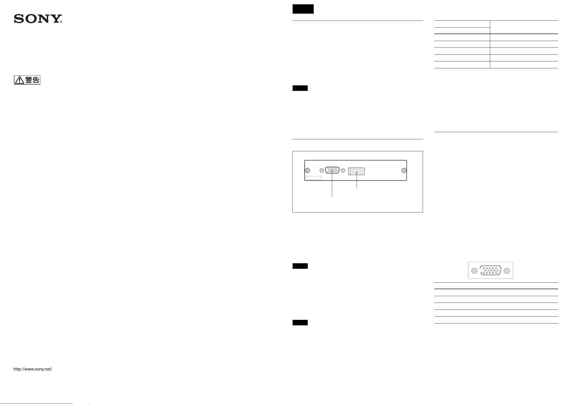
各部の名称と働き
MONITOR
HFBK-XG1
2DIPスイッチ (カバー内)
1MONITOR端子
1
MONITOR
映像出力です。DIPスイッチ の設 定によって、出力信号を切り換えることが
できます。
DIP
ご注意
定)
ご注意
スイッチ
2
MONITOR端子の出力条件を設定します。
装着した機器の電源を切ってからDIPスイッチを 切り換えてください。
スイッチ
同期信号をG 信号に付加するかどうかを選択します。
上(SynconG):G 信号に同期信号が付加されて出力されます。(工場設
下(Nosync):同期信号は付加されません。
•スイッチ 1を 下 に 設定すると映像が 表 示されない 場 合は、上に切り換えて
ください。
•スイッチ 1 を 上に 設定すると映像のグリーンが強調される場合は、下に切
り換えてください。このとき、同期出力HD/VDをモニターに接続してくだ
さい。
スイッチ
出力信号の規格およびアスペクト比を 切り換えます 。
それぞれ下の位置 にするとON、上の位置にするとOFFになります。工場
出荷時はすべてOFFに設定されています。
(モニター出力)端子(
1
2、 3、4
D-sub15
ピン)
スイッチ設定
SW2 SW3 SW4
OFF 任意 任意 WXGA
ON OFF OFF XGA(16:9レターボックス)
ON OFF ON XGA(4:3エッジクロップ)
ON ON OFF VGA(16:9レターボックス)
ON ON ON VGA(4:3エッジクロップ)
スイッチ
使用するモニターに合わせてVDの極性を選択します。
上:負極性(工場設定)
下:正極性
スイッチ
機能しません。工場設定(OFF)のままで使用してください 。
5
6、 7、8
規格(アスペクト比)
仕様
一般
電源 +12VDC、270mA(装着した機器より供給)
動作温度 5℃〜40℃
保存温度 –20℃〜+60℃
保存湿度 20%〜90%(相対湿度、結露なし)
外形寸法 134× 26.2×112.8mm(幅/ 高さ/奥行き)
(端子部および取り付けネジ部含まず)
質量 約0.16kg
出力端子
MONITOR D-sub15ピン(1)
ビデオ出力 R/G/B
VGA(640× 480、60Hz)
XGA(1024×768、60Hz)
WXGA(1280× 768、60Hz)
同期出力 HD/VD(TTLレベル)
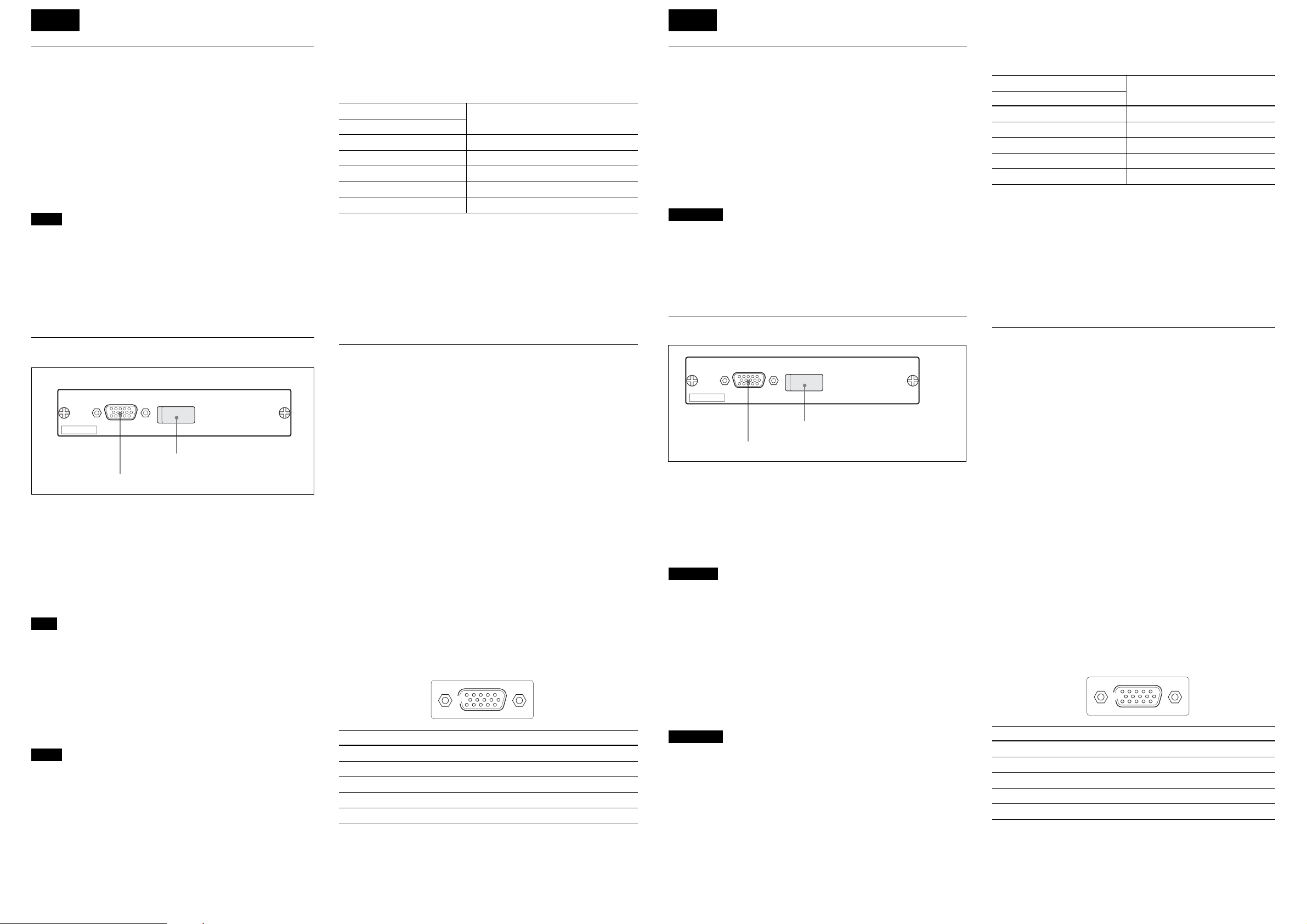
ピン配 列
ピン 信号 ピン 信号 ピン 信号
1R(X) 6 R(G) 11 NC
2G(X) 7 G(G) 12 NC
3 B(X) 8 B(G) 13 HD
4NC 9NC 14VD
5GND 10GND15NC
付属品
オペレーションマニュアル(1)
本機の仕様および外観は、改良のため予告なく変更することがありま
すが、ご了承ください。
51
10
15 11
6
English
Français
Overview
The HFBK-XG1 is an optional board designed to be
installed in the following apparatuses:
•HFU-X310 HD Camera Interface Unit
•BRC-H700 HD 3CCD Color Video Camera
•BRU-H700 HD Optical Multiplex Unit
The board supplies images from the color video camera
connected to the apparatus that accommodates the board
after conversion to VGA, XGA, or WXGA.
Notes
•The picture may skip as video signals are converted to
the VESA standards.
•The H (horizontal) phase may be shifted, depending on
the settings of the display or video projector. In such a
case, adjust the H phase on the display or video
projector.
Locations and Functions of Parts
MONITOR
HFBK-XG1
2 DIP switches (behind the cover)
1 MONITOR connector
1MONITOR connector (D-sub 15-pin)
For video output. The output signal can be specified by
setting the DIP switches.
2DIP switches
To configure the type of output from the MONITOR
connector.
Note
Turn the apparatus that accommodates the board off
before changing the DIP switch settings.
Switch 1
Specifies whether to add a sync signal to the G signal:
Upper (Sync on G): To output the G signal with a sync
signal added (factory setting)
Lower (No Sync): No to add a sync signal to the G signal
Notes
•If no image is displayed with Switch 1 set to the lower
position, move it to the upper position.
•If green in the image is emphasized with Switch 1 set to
the upper position, move it to the lower position.
Connect the HD and VD sync outputs to the monitor.
Switches 2, 3, 4
Select the standards and the aspect ratio of the output
signal.
Each switch is set to ON in its upper position and to OFF in
its lower position.
All the switches are set to OFF at the factory.
Switch settings
SW2 SW3 SW4
OFF any any WXGA
ON OFF OFF XGA (16:9 letterbox)
ON OFF ON XGA (4:3 edge crop)
ON ON OFF VGA (16:9 letterbox)
ON ON ON VGA (4:3 edge crop)
Standards (Aspect ratio)
Switch 5
Select the VD polarity according to the monitor to be used.
Upper: Negative (factory setting)
Lower: Positive
Switches 6, 7, 8
Not used. Leave them in their factory-set positions.
Specifications
General
Power requirements
+12 V DC, 270 mA (supplied from the
apparatus that accommodates the board)
Operating temperature
5°C to 40°C (41°F to 104°F)
Storage temperature
–20°C to +60°C (–4°F to +140°F)
Storage humidity
Dimensions 134 × 26.2 × 112.8 mm (w/h/d)
Mass Approx. 0.16 kg (6 oz)
Outputs
MONITOR D-sub 15-pin (1)
Video output R/G/B
Sync output HD/VD (TTL level)
Pin assignment
Pin Signal Pin Signal Pin Signal
1R (X)6R (G) 11 NC
2G (X)7G (G) 12 NC
3B (X)8B (G) 13 HD
4NC 9NC 14 VD
5 GND 10 GND 15 NC
Supplied accessory
Operation Manual (1)
Design and specifications are subject to change without
notice.
20% to 90% (relative, no condensation)
(53/8 × 11/16 × 41/2 inches)
not including projecting parts
VGA (640×480, 60 Hz)
XGA (1024×768, 60 Hz)
WXGA (1280×768, 60 Hz)
51
10
15 11
6
Description générale
La HFBK-XG1 est une carte en option conçue pour être
installée dans les appareils suivants :
•Interface caméra HD HFU-X310
•Camera vidéo couleur HD 3CCD BRC-H700
•Module multiplex optique HD BRU-H700
La carte fournit les images provenant d’une caméra vidéo
couleur connectée à l’appareil qui contient la carte après la
conversion à VGA, XGA ou WXGA.
Remarques
•L’image peut sauter de temps en temps car les signaux
vidéo sont convertis en normes VESA.
•La phase H (horizontale) peut être décalée, en fonction des
réglages de l’écran ou du projecteur vidéo. Dans un tel cas,
ajustez la phase H sur l’écran ou le projecteur vidéo.
Emplacement et fonction des pièces
MONITOR
HFBK-XG1
2 Commutateurs DIP (derrière le cache)
1 Connecteur MONITOR
1Connecteur MONITOR (D-sub 15 broches)
Pour la sortie vidéo. Le signal de sortie peut être spécifié en
réglant les commutateurs DIP.
2Commutateurs DIP
Pour configurer le type de sortie du connecteur MONITOR.
Remarque
Mettez l’appareil contenant la carte hors tension avant de
changer les réglages des commutateurs DIP.
Commutateur 1
Permet de spécifier si un signal de synchro doit être ajouté au
signal V :
Position supérieure (Synchro sur V) : Sortie du signal V
avec un signal de synchro ajouté (réglage d’usine)
Position inférieure (Pas de synchro) : Pas d’ajout de signal
de synchro au signal V
Remarques
•Si aucune image n’est affichée avec le Commutateur 1 réglé
en position inférieure, déplacez-le en position supérieure.
•Si l’image contient trop de vert avec le Commutateur 1
réglé en position supérieure, déplacez-le en position
inférieure. Connectez les sorties synchro HD et VD au
moniteur.
Commutateurs 2, 3, 4
Sélectionnez les normes et le format d’image du signal de
sortie. Chaque commutateur est réglé sur ON en position
supérieure et sur OFF en position inférieure.
Tous les commutateurs sont réglés sur OFF à l’usine.
Réglages des commutateurs
SW2 SW3 SW4
OFF tous tous WXGA
ON OFF OFF XGA (16:9 letterbox)
ON OFF ON XGA (4:3 coupure des contours)
ON ON OFF VGA (16:9 letterbox)
ON ON ON VGA (4:3 coupure des contours)
Normes (Format d’image)
Commutateur 5
Sélectionnez la polarité VD en fonction du moniteur
utilisé.
Position supérieure : Négative (réglage d’usine)
Position inférieure : Positive
Commutateurs 6, 7, 8
Non utilisée. Gardez les réglages d’usine tels quels.
Spécifications
Généralités
Alimentation +12 V CC, 270 mA (fourni par
l’appareil contenant la carte)
Température de fonctionnement
5 °C à 40 °C (41 °F à 104 °F)
Température de rangement
–20 °C à +60 °C (–4 °F à +140 °F)
Humidité de rangement
20 % à 90 % (relatif, sans
condensation)
Dimensions 134 × 26,2 × 112,8 mm (l/h/p)
Poids Environ 0,16 kg (6 oz)
Sorties
MONITOR D-sub 15 broches (1)
Sortie vidéo R/V/B
Sortie synchro HD/VD (niveau TTL)
Affectation des broches
Broche Signal Broche Signal Broche Signal
1R (X)6R (G) 11 NC
2V (X)7V (G) 12 NC
3B (X)8B (G) 13 HD
4NC 9NC 14 VD
5 GND 10 GND 15 NC
Accessoires fournis
Mode d’emploi (1)
La conception et les spécifications sont susceptibles d’être
modifiées sans préavis.
3
/8 × 11/16 × 41/2 pouces)
(5
pièces saillantes non comprises
VGA (640×480, 60 Hz)
XGA (1024×768, 60 Hz)
WXGA (1280×768, 60 Hz)
51
10
15 11
6
 Loading...