

Page 1
SD INTERFACE BOARD
HFBK-SD1
電気製品は、安全のための注意事項を守らないと、
火災や人身事故になることがあります。
ご使用にあたっては、設置先の機器に付属のオペレーションマニュア
•
ルの「安全のために」をよくお読みください。
装着のしかたは、設置先の機器に付属のオペレーションマニュアルの
•
「オプション基板の装着」をご覧ください。
For installation instructions, refer to “Mounting an Optional Board”
in the Operation Manual supplied with the product in which this
board is to be mounted.
OPERATION MANUAL
[Japanese/English]
For the customers in the U.S.A.
This equipment has been tested and found to comply with the limits
for a Class A digital device, pursuant to Part 15 of the FCC Rules.
These limits are designed to provide reasonable protection against
harmful interference when the equipment is operated in a
commercial environment. This equipment generates, uses, and
can radiate radio frequency energy and, if not installed and used in
accordance with the instruction manual, may cause harmful
interference to radio communications. Operation of this equipment
in a residential area is likely to cause harmful interference in which
case the user will be required to correct the interference at his own
expense.
You are cautioned that any changes or modifications not expressly
approved in this manual could void your authority to operate this
equipment.
All interface cables used to connect peripherals must be shielded in
order to comply with the limits for a digital device pursuant to
Subpart B of Part 15 of FCC Rules.
This device complies with part 15 of FCC Rules.
Operation is subject to the following two conditions: (1) This device
may not cause harmful interference, and (2) this device must
accept any interference received, including interference that may
cause undesired operation.
For customers in Canada
This Class A digital apparatus complies with Canadian ICES-003.
For the customers in Europe
This product with the CE marking complies with the EMC Directive
issued by the Commission of the European Community.
Compliance with this directive implies conformity to the following
European standards:
• EN55103-1: Electromagnetic Interference (Emission)
• EN55103-2: Electromagnetic Susceptibility (Immunity)
This product is intended for use in the following Electromagnetic
Environment(s):
E1 (residential), E2 (commercial and light industrial),
E3 (urban outdoors) and E4 (controlled EMC environment, ex. TV
studio).
日本語
概要
HFBK-SD1は、以下の機器に装着して使用するオプションボードです。
• HDカメラインターフェースユ ニットHFU-X310
• HD3CCDカラービデオカメラBRC-H700
• HDオプチカルマルチプレックスユニットBRU-H700
装着した機器に接続したカラービデ オカメラからの映 像をダウンコンバートし
て、SD-SDI信号およびアナログ信号に変換して出力します。出力信号のアス
ペクト比 に は、16:9レターボックス、4:3エッジクロップ(切り出し)、スクイーズを
選択できます。アナログ信 号は、コン ポ ーネント/コンポジット/Sビデ オも出 力
可能です。
エンベ デッドオーディオとタイムコード対応のHFU-X310に装着したときは、
HFU-X310に入力されたHD-SDI信号のエンベデッドオーディオとタイムコード
をSD-SDI信号に重畳して出力します。
ご注意
タイムコードは 下 記のライン(固定)に出力されます。
映像信号が
LTC:13ライン LTC:9ライン
VITC1:12ライン、14ライン VITC1:8ライン、10ライン
VITC2:275ライン、277ライン VITC2:321ライン、323ライン
NTSC(59.94i
)のとき 映像信号が
PAL(50i
)のとき
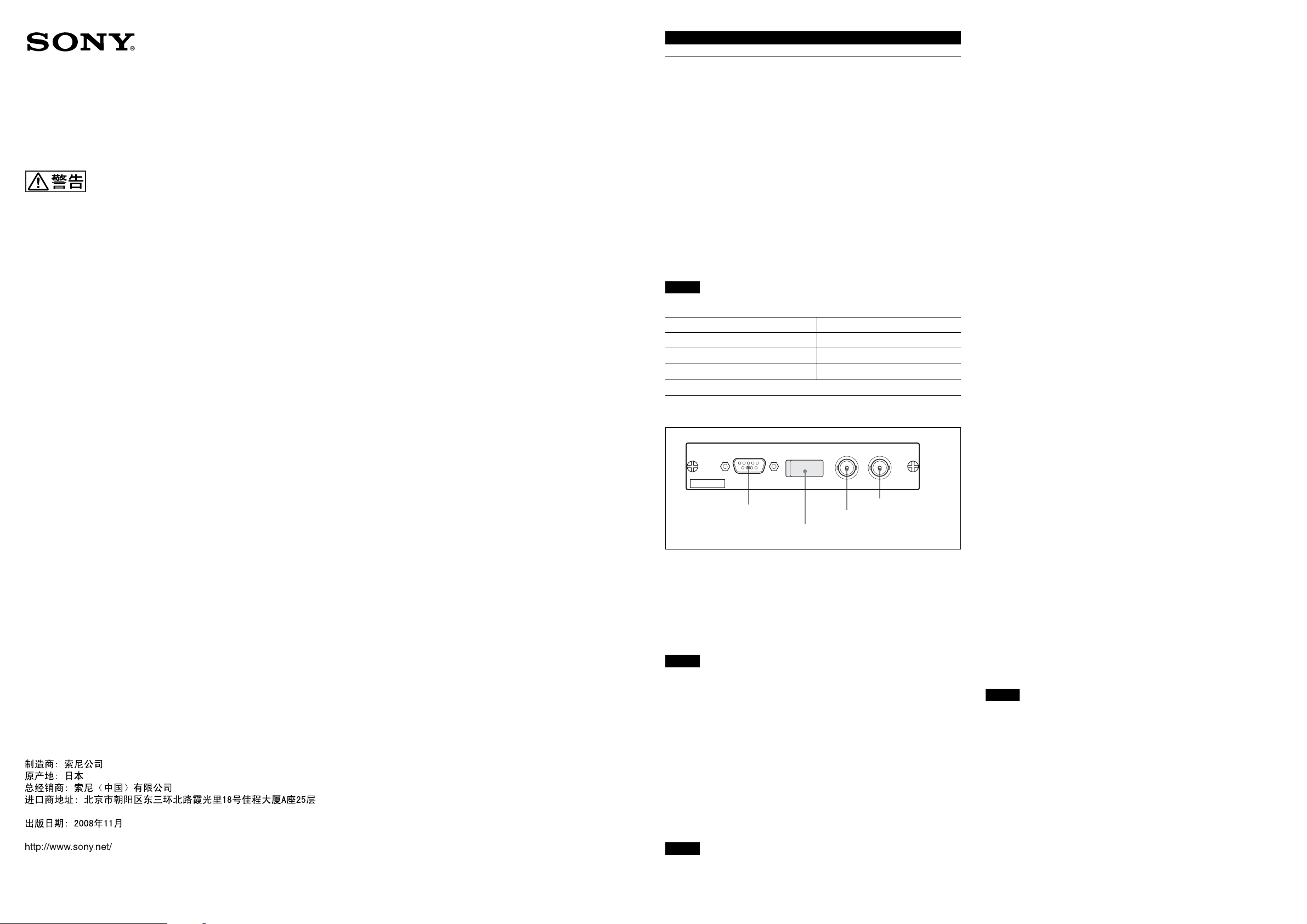
各部の名称と働き
MONITOR VIDEO SDI
HFBK-SD1
4SDI端子
1MONITOR端子
2DIPスイッチ (カバー内)
3VIDEO端子
• BRC-H700またはBRU-H700に装着の際は、装着する機器がセットアップ 付
加機能対応バージョンである必要があります。
◆対応バージョンかどうかは、お買い上げ店またはソニーの営業担当者にご確認
ください。
スイッチ2(
スイッチ 3でMONITOR 端子の出力に RGBを、スイッチ 1 で同期信号付加
(AddSync)を選択しているとき、同期信号をR/G/B各信号に付加するか、G
信号にのみ付加するかを選択します。
上( SynconALL):R/G/B各信号に同期信号が付加されて出力されます。
(工場設定)
下( SynconG):G 信号に同期信号が付加されて出力されます。
スイッチ
MONITOR端子のコンポーネント出 力を 切り換えます。
上( YPbPr):コンポ ーネント信号を 出力します 。(工場設定)
下( RGB):RGB信号を出力します。
スイッチ
MONITOR端子の 6ピンから出力される信号を切り換えます。
上(コン ポジット):アナログコンポ ジット信 号を 出 力します。(工場設定)
下(Y): S ビデ オ信 号 の Y 信 号を 出 力します。このとき9ピンからC 信号が 出
力されます。
スイッチ
出力する信号のアスペクト比 を選 択します 。
上( 16:9):アス ペ クト比 16:9(レターボックス)になります。スイッチ 6 は 無 効
になります。(工場設定)
下( 4:3):アスペ クト比 4:3 になります。スイッチ 6 で エッジクロップ か スクイー
ズを選択します。
スイッチ
スイッチ 5 でアスペクト比 4 : 3 を 選 択し たとき有 効に なります 。
上( Crop):エッジクロップが出力されます。(工場設定)
下( Squeeze):スクイーズが出力されます。
Sync on G
3(RGB/YPbPr
(コンポジット/Sビデオ)
4
5(16:9/4:3
6(Crop/Squeeze
)
)
)
)
Sony Corporation 2005
Printed in Japan 2008.11.13
3-869-802-06(1)
The manufacturer of this product is Sony Corporation, 1-7-1 Konan,
Minato-ku, Tokyo, Japan.
The Authorized Representative for EMC and product safety is Sony
Deutschland GmbH, Hedelfinger Strasse 61, 70327 Stuttgart,
Germany.
1
MONITOR
アナログ映 像出力 で す。DIPスイッチの設定によって、出力信号を切り換える
ことが できま す。
2
DIP
信号の出力条件を設定します。
ご注意
装着した機器の電源を切ってからDIPスイッチを切り換えてください 。
スイッチ
スイッチ 3でMONITOR端子の出力にRGBを選択しているときは、出力信号
に同期信号を付加するかどうかを選択します。
上( AddSync):同 期信 号が 付加されます。(工場設定)
下( NoSync):同 期 信号を付加しません。
スイッチ 3でMONITOR 端子の出力にYPbPrを選択しているときは、出力信
号に 7.5%のセットアップ を 付 加 す るか どうかを 選 択し ま す。
上( NoSetup):セットアップ を 付 加し ませ ん 。(工場設定)
下( AddSetup):セットアップ が 付 加され ます 。
ご注意
(モニター出力)端子(
スイッチ
1(Sync/Setup
)
D-sub 9
ピン)
• セットアップ の付加は、映像信号がNTSC(59.94i)のときのみ有効です。
• セットアップ は 、MONITOR端子とVIDEO端子の出力に付加されます。
スイッチ
同期信号に対して映像出力をディレイさせるかどうかを選択します。
上( NoDelay):ディレイなし( 工 場 設定)。
下( Delay):8 9 または 9 0ライン(HD)ディレイさせます。
スイッチ
スイッチ 7 で ディレイ選択 時に映 像 出力と同期 信号との位相 差を設 定します。
上( 89H):8 9 ライン(HD)ディレイさせます(工 場設定)。
下( 90H):9 0 ライン(HD)ディレイさせます 。
ご注意
スイッチ 7、8は、ディレイ機能対応バージョンの HD カメラインターフェースユ
ニットHFU-X310に装着したときのみ有効です。
◆スイッチ 7、8の機能について詳しくは、HFU-X310のオペレーションマ ニュアル
3
画像確認用にアナログコンポジット信 号を 出 力します 。DIPスイッチの 設定に
よってアスペクト比を 選 択します 。
4
ダウンコンバートしたSD-SDI信号を出力します。DIPスイッチ の設 定 によって、
アスペクト比を 選 択します 。
7(Delay
8(89H/90H
をご覧ください。
VIDEO
(デジタル出力)端子(
SDI
)
)
(アナログコンポジット映像)端子(
型)
BNC
BNC
型)
Page 2
仕様
一般
電源 +12VDC、400mA(装着した機器より供給)
動作温度 5℃〜40℃
保存温度 –20℃〜+60℃
保存湿度 20%〜90%(相対湿度、結露なし)
外形寸法 134× 26.2 × 112.8mm(幅/高さ/ 奥行き)
(端子部および取り付けネジ部含まず)
質量 約0.16kg
出力端子
VIDEO BNC型(1)
コンポジット:1.0Vp-p、75 Ω
SDI BNC型(1)
SMPTE259M、75 Ω
MONITOR D-sub9ピン(1)
出力レベル コンポジット:1.0Vp-p、75 Ω
コンポ ーネントY:1.0Vp-p
Pb/Pr:0.7Vp-p、75Ω
R/G/B:1.0Vp-p(Sync付き)、75 Ω
Sビデオ Y:1.0Vp-p
C:
コンポジットの クロマ 信 号と同レ ベ ル
SYNC:0.3Vp-p、75Ω
ピン配 列
ピン 信号 ピン 信号 ピン 信号
1GND 4 G/Y 7 SYNC
2GND 5 B/Pb 8 GND
3 R/Pr 6 Composite/Y 9 –/C
付属品
オペレーションマニュアル(1)
本機の仕様および外観は、改良のため予告なく変更することがありますが、ご
了承ください。
お使いになる前に、必ず動作確認を行ってください。故障その他に伴う営
業上の機会損失等は保証期間中および保証期間経過後にかかわらず、補
償はいたしかねますのでご了承ください。
51
96
English
Overview
The HFBK-SD1 is an optional board designed to be installed in the
following apparatuses:
• HFU-X310 HD Camera Interface Unit
• BRC-H700 HD 3CCD Color Video Camera
• BRU-H700 HD Optical Multiplex Unit
The board down-converts images from the color video camera
connected to the apparatus that accommodates the board and
supplies them as SD-SDI and analog signals. You can select the
output signal aspect ratio from among 16:9 letterbox, 4:3 edge
crop, and squeeze. As analog outputs, component, composite and
S video signals are available.
When the board is installed in an HFU-X310 that supports
embedded audio and time code, the embedded audio and time code
of HD-SDI signal supplied to the HFU-X310 are embedded in the
SD-SDI output signal.
Note
The time code is output to the following lines (fixed).
When video signal is When video signal is
NTSC (59.94i) PAL (50i)
LTC: Line 13 LTC: Line 9
VITC1: Lines 12 and 14 VITC1: Lines 8 and 10
VITC2: Lines 275 and 277 VITC2: Lines 321 and 323
Locations and Functions of Parts
MONITOR VIDEO SDI
HFBK-SD1
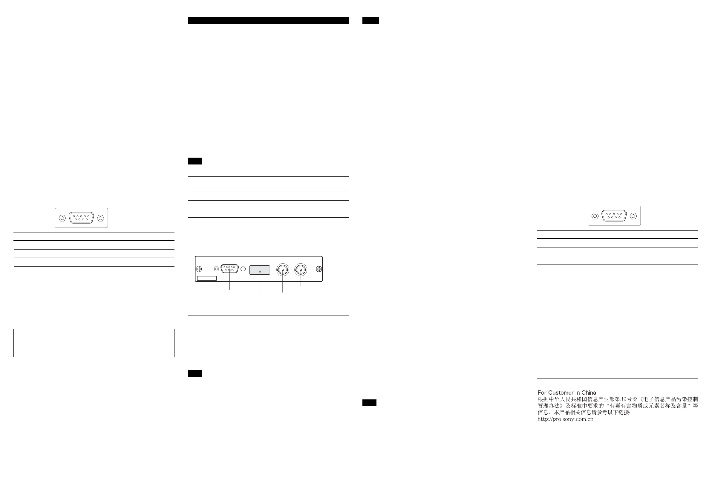
1 MONITOR connector
2 DIP switches (behind the cover)
3 VIDEO connector
1 MONITOR connector (D-sub 9-pin)
For analog video output. The configuration of the output signal
can be specified by setting the DIP switches.
2 DIP switches
To configure the output signals.
Note
Turn the apparatus that accommodates the board off before
changing the DIP switch settings.
4 SDI connector
Notes
• Setup can be added only when the video signal is NTSC (59.94i).
• Setup is added to both the MONITOR and VIDEO connector
outputs.
•When this board is mounted in a BRC-H700 or BRU-H700,
Setup adding is allowed only when the BRC-H700 or BRU-H700
is in a version that can control the Setup adding function of this
board.
For information of the version, please ask your Sony representative.
Switch 2 (Sync on G)
Specifies whether to add a sync signal to each of the R, G, and B
signals or only to the G signal when “RGB” is selected with
Switch 3 and “Add Sync” is selected with Switch 1 for the
MONITOR connector output:
Upper (Sync on ALL): To output each of the R, G, and B signals
with a sync signal added (factory setting)
Lower (Sync on G): To output the G signal with a sync signal
added
Switch 3 (RGB/YPbPr)
Selects the component output from the MONITOR connector:
Upper (YPbPr): To output component signals (factory setting)
Lower (RGB): To output RGB signals
Switch 4 (Composite/S Video)
Specifies the signal to be supplied from pin 6 of the MONITOR
connector:
Upper (Composite): To output analog composite signals (factory
setting)
Lower (Y): To output the Y signal of S video. The C signal is
output from pin 9
Switch 5 (16:9/4:3)
Selects the aspect ratio of the output signal:
Upper (16:9): To select 16:9 letterbox (factory setting) (Switch 6
becomes invalid.)
Lower (4:3): To select 4:3. Select edge crop or squeeze with
Switch 6
Switch 6 (Crop/Squeeze)
Valid when 4:3 aspect ratio is selected with Switch 5:
Upper (Crop): To output edge crop (factory setting)
Lower (Squeeze): To output squeeze
Switch 7 (Delay)
Specifies whether to delay video output with respect to a sync
signal:
Upper (No Delay): Not to delay (factory setting)
Lower (Delay): To delay 89 or 90 lines (HD)
Switch 8 (89H/90H)
Selects the phase difference to delay when “Delay” is selected
with Switch 7:
Upper (89H): 89 lines (HD) (factory setting)
Lower (90H): 90 lines (HD)
Specifications
General
Power requirements +12 V DC, 400 mA (supplied from the
apparatus that accommodates the board)
Operating temperature
5°C to 40°C (41°F to 104°F)
Storage temperature –20°C to +60°C (–4°F to +140°F)
Storage humidity
Dimensions 134 × 26.2 × 112.8 mm (w/h/d)
Mass Approx. 0.16 kg (6 oz)
Outputs
VIDEO BNC type (1)
SDI BNC type (1), SMPTE259M, 75 Ω
MONITOR D-sub 9-pin (1)
Output level Composite: 1.0 Vp-p, 75 Ω
Pin assignment
Pin Signal Pin Signal Pin Signal
1 GND 4 G/Y 7 SYNC
2 GND 5 B/Pb 8 GND
3 R/Pr 6 Composite/Y 9 –/C
Supplied accessory
Operation Manual (1)
Design and specifications are subject to change without notice.
Note
Always verify that the unit is operating properly before use.
SONY WILL NOT BE LIABLE FOR DAMAGES OF ANY KIND
INCLUDING, BUT NOT LIMITED TO, COMPENSATION OR
REIMBURSEMENT ON ACCOUNT OF THE LOSS OF
PRESENT OR PROSPECTIVE PROFITS DUE TO FAILURE
OF THIS UNIT, EITHER DURING THE WARRANTY PERIOD
OR AFTER EXPIRATION OF THE WARRANTY, OR FOR ANY
OTHER REASON WHATSOEVER.
20% to 90% (relative, no condensation)
(53/8 × 11/16 × 41/2 inches)
not including projecting parts
Composite: 1.0 Vp-p, 75 Ω
Component Y: 1.0 Vp-p
Pb/Pr: 0.7 Vp-p, 75 Ω
R/G/B: 1.0 Vp-p (with Sync), 75 Ω
S video Y: 1.0 Vp-p
C: Same level as with the chroma
signal of composite
Sync: 0.3 Vp-p, 75 Ω
51
96
Switch 1 (Sync/Setup)
When RGB output is selected for the MONITOR connector with
Switch 3, this switch specifies whether to add a sync signal to the
output signals:
Upper (Add Sync): To add a sync signal (factory setting)
Lower (No Sync): Not to add any sync
When YPbPr output is selected for the MONITOR connector with
Switch 3, this switch specifies whether to add 7.5% Setup to the
output signals:
Upper (No Setup): Not to add any Setup (factory setting)
Lower (Add Setup): To add Setup
Note
Switches 7 and 8 are valid only when the board is installed in an
HFU-X310 of a version that supports the Delay function.
For details on the functions of Switches 7 and 8, refer to the Operation
Manual of the HFU-X310.
3 VIDEO (analog composite) connector (BNC type)
Outputs analog composite signals for checking images. The aspect
ratio can be selected with the DIP switches.
4 SDI connector (BNC type)
Outputs down-converted SD-SDI signals. The aspect ratio can be
selected with the DIP switches.
 Loading...