

Page 1

HD COLOR CAMERA
HDC1000
HDC1400
HDC1500
HDC1550
HDC1580
MAINTENANCE MANUAL
Volume 1 1st Edition (Revised 4)
Serial No. 10001 and Higher: HDC1000 (UCJ)
Serial No. 40001 and Higher: HDC1000 (CE)
Serial No. 10001 and Higher: HDC1400 (UC)
Serial No. 10001 and Higher: HDC1500 (SY)
Serial No. 40001 and Higher: HDC1500 (CE)
Serial No. 10001 and Higher: HDC1550 (UC)
Serial No. 40001 and Higher: HDC1550 (CE)
Serial No. 400001 and Higher: HDC1550 (CE)
Serial No. 50001 and Higher: HDC1580 (CN)
Page 2

! WARNING
CLASS 1 LASER PRODUCT
LASER KLASSE 1 PRODUKT
LUOKAN 1 LASERLAITE
KLASS 1 LASER APPARAT
This manual is intended for qualified service personnel only.
To reduce the risk of electric shock, fire or injury, do not perform any servicing other than that
contained in the operating instructions unless you are qualified to do so. Refer all servicing to
qualified service personnel.
! WARNUNG
Die Anleitung ist nur für qualifiziertes Fachpersonal bestimmt.
Alle Wartungsarbeiten dürfen nur von qualifiziertem Fachpersonal ausgeführt werden. Um die
Gefahr eines elektrischen Schlages, Feuergefahr und Verletzungen zu vermeiden, sind bei
Wartungsarbeiten strikt die Angaben in der Anleitung zu befolgen. Andere als die angegeben
Wartungsarbeiten dürfen nur von Personen ausgeführt werden, die eine spezielle Befähigung
dazu besitzen.
! AVERTISSEMENT
Ce manual est destiné uniquement aux personnes compétentes en charge de l’entretien. Afin
de réduire les risques de décharge électrique, d’incendie ou de blessure n’effectuer que les
réparations indiquées dans le mode d’emploi à moins d’être qualifié pour en effectuer d’autres.
Pour toute réparation faire appel à une personne compétente uniquement.
Laser Diode Properties
Wave length : 1310 ± 40 nm
Emission duration : Pulse Modulation
Laser output power : 141
Use of controls or adjustments or performance of
procedures other than those specified herein
may result in hazardous radiation exposure.
The use of optical instruments with this product
will increase eye hazard.
CAUTION
CAUTION
+37
_29
uW
This HD Color Camera is classified as a CLASS 1
LASER PRODUCT.
HDC1000/V1(E)
Page 3

CAUTION
ADVARSEL!
Lithiumbatteri-Eksplosionsfare ved fejlagtig
håndtering.
Udskiftning må kun ske med batteri
af samme fabrikat og type.
Levér det brugte batteri tilbage til leverandøren.
Danger of explosion if battery is incorrectly replaced.
Replace only with the same or equivalent type
recommended by the manufacturer.
Dispose of used batteries according to the
manufacturer’s instructions.
Vorsicht!
Explosionsgefahr bei unsachgemäßem Austausch
der Batterie.
Ersatz nur durch denselben oder einen vom
Hersteller empfohlenen ähnlichen Typ. Entsorgung
gebrauchter Batterien nach Angaben des
Herstellers.
ATTENTION
Il y a danger d’explosion s’il y a remplacement
incorrect de la batterie.
Remplacer uniquement avec une batterie du même
type ou d’un type équivalent recommandé par le
constructeur.
Mettre au rebut les batteries usagées conformément
aux instructions du fabricant.
ADVARSEL
Lithiumbatteri - Eksplosjonsfare.
Ved utskifting benyttes kun batteri som
anbefalt av apparatfabrikanten.
Brukt batteri returneres
apparatleverandøren.
VARNING
Explosionsfara vid felaktigt batteribyte.
Använd samma batterityp eller en likvärdig typ
som rekommenderas av apparattillverkaren.
Kassera använt batteri enligt gällande
föreskrifter.
VAROITUS
Paristo voi räjähtää jos se on virheellisesti
asennettu.
Vaihda paristo ainoastaan laitevalmistajan
suosittelemaan tyyppiin.
Hävitä käytetty paristo valmistajan ohjeiden
mukaisesti.
HDC1000/V1(E)
1 (P)
Page 4

Voor de klanten in Nederland
Gooi de batterij niet weg maar lever deze in als klein
chemisch afval (KCA).
Für Kunden in Deutschland
Entsorgungshinweis: Bitte werfen Sie nur entladene
Batterien in die Sammelboxen beim Handel oder den
Kommunen. Entladen sind Batterien in der Regel dann,
wenn das Gerät abschaltet und signalisiert “Batterie
leer” oder nach längerer Gebrauchsdauer der Batterien
“nicht mehr einwandfrei funktioniert”. Um
sicherzugehen, kleben Sie die Batteriepole z.B. mit
einem Klebestreifen ab oder geben Sie die Batterien
einzeln in einen Plastikbeutel.
For the customers in Taiwan only
2 (P)
HDC1000/V1(E)
Page 5

Table of Contents
Manual Structure
Purpose of this manual ................................................................. 4
Related manuals ........................................................................... 4
1. Service Overview
1-1. Checking before Installation ........................................... 1-1
1-1-1. Checking the ROM and Software Version ............ 1-1
1-2. Connectors and Cables ...................................................1-2
1-2-1. Connector Input/Output Signals ............................1-2
1-2-2. Wiring Diagrams for Cables .................................1-9
1-2-3. Connection Connectors/Cables ........................... 1-10
1-2-4. Note in Connecting CCU Connector
(HDC1000/1400/1500/1580) .............................. 1-10
1-3. Location of Printed Circuit Boards ............................... 1-11
1-4. Opening/Closing the Side Panel ................................... 1-14
1-5. Switch Settings ............................................................. 1-15
1-6. Notes for Replacing Parts ............................................. 1-19
1-6-1. Notes for Replacing the Flexible Card Wire .......1-19
1-6-2. Notes for Replacing the Board ............................ 1-20
1-6-3. Notes for Replacing the Connector
on the Board ........................................................ 1-20
1-6-4. Notes for HDC1400 and HDC1580 .................... 1-20
1-7. Cleaning the Vent Portion of the Fan
(HDC1400/1500/1550/1580) ........................................1-21
1-8. Cleaning of Connector/Cable
(HDC1000/1400/1500/1580) ........................................1-22
1-8-1. When the Optical Connector Cleaner
(Commercially Available) is Available ............... 1-22
1-8-2. When the Optical Connector Cleaner
(Commercially Available) is not Available ........ 1-23
1-9. Setting the Utility Out Voltage (HDC1000) .................1-24
1-10. Notes on Flexible Card Wire ........................................ 1-24
1-10-1. Disconnecting/Connecting Flexible Card
Wire .....................................................................1-24
1-10-2. Forming of the Flexible Card Wire ..................... 1-26
1-11. Notes on Replacement of Circuit Board .......................1-27
1-11-1. Description on EEPROM Data ........................... 1-27
1-11-2. Adjustment after Replacement of Board .............1-27
1-11-3. Adjustment and Setting Items when
Replacing AT-163 Board .................................... 1-27
1-12. Setting Microphone Power and Intercoms ...................1-28
1-12-1. How to Supply a Power of +12 V ....................... 1-28
1-12-2. Setting Intercoms .................................................1-28
1-13. Upgrading the Software ................................................1-29
1-13-1. Upgrading the MAIN Program ...........................1-29
1-13-2. Upgrading the Boot Program ..............................1-30
1-14. Writing and Rewriting the PLD Internal Data .............. 1-31
1-15. Note on Replacement of Lithium Battery ..................... 1-32
1-16. Recommended Replacing Parts .................................... 1-33
1-16-1. HDC1000 ............................................................1-33
1-16-2. HDC1400/1500/1550/1580 ................................. 1-34
1-16-3. Periodic Check/Replacement Parts ..................... 1-35
1-17. Description of CCD Block Number .............................1-36
1-18. Optional Fixtures .......................................................... 1-36
1-19. Notes on Repair Parts ................................................... 1-36
1-20. Unleaded Solder ............................................................1-36
2. Replacement of Main Parts
2-1. Replacing the CCD Unit .................................................2-1
2-1-1. HDC1000 ..............................................................2-1
2-1-2. HDC1400/1500/1550/1580 ................................... 2-3
2-2. Replacement of CCD Unit Boards ................................. 2-4
2-2-1. DR-528 Board ....................................................... 2-4
2-2-2. CN-2579 Board ..................................................... 2-4
2-2-3. PA-317 Board ........................................................ 2-5
2-2-4. TG-243 Board .......................................................2-5
2-2-5. CN-2578 Board ..................................................... 2-6
2-3. Replacing the Filter Disk Unit ........................................2-7
2-3-1. HDC1000 ..............................................................2-7
2-3-2. HDC1400/1500/1550/1580 ................................... 2-7
2-4. Replacing the Fan (HDC1000) ....................................... 2-8
2-4-1. DC Fan (TOP) ....................................................... 2-8
2-5. Replacing the Fan (HDC1400/1500/1550/1580) ............ 2-9
2-5-1. DC Fan (Front) ......................................................2-9
2-5-2. DC Fan (Rear) ..................................................... 2-10
2-6. Replacing the VF DISP Switches
(HDC1400/1500/1550/1580) (SW-1237 Board) .......... 2-11
2-7. Replacing the Side Switch Panel Assembly
(HDC1400/1500/1550/1580) (SW-1240 Board) .......... 2-12
HDC1000/V1(E)
1
Page 6

2-8. Replacing the Connectors
(HDC1400/1500/1550/1580) ........................................2-12
2-8-1. EARPHONE Jack (CN-2640 Board) .................. 2-12
2-8-2. DC IN Connector (CN-2623 Board) ................... 2-13
2-8-3. INTERCOM 1/2 Connector
(CN-2618 Board) ................................................. 2-14
2-8-4. LENS Connector (CN-2616 Board) ....................2-14
2-8-5. MIC 1 IN Connector (CN-2615 Board) .............. 2-15
2-8-6. REMOTE Connector (CN-2622 Board) ............. 2-15
2-8-7. RET IN, TEST OUT Connector
(CN-2620 Board) ................................................. 2-16
2-8-8. SDI 1 Connector (HDC1500) .............................. 2-16
2-8-9. SDI 2 Connector (HDC1500)
SDI Connector (HDC1400/1550) ........................ 2-17
2-8-10. BUILD UP Connector
(Hot Shoe Assembly) .......................................... 2-17
2-9. Replacing the Encapsulated Cable Assembly/
TRIAX Assembly ......................................................... 2-18
2-9-1. HDC1000 (Encapsulated Cable Assembly) ........ 2-18
2-9-2. HDC1400/1500/1580
(Encapsulated Cable Assembly) .......................... 2-19
2-9-3. HDC1550 (TRIAX Assembly) ............................ 2-20
2-10. Replacing the DC/DC Converter Unit ..........................2-21
2-10-1. HDC1000 ............................................................ 2-21
2-10-2. HDC1400/1500/1550/1580 ................................. 2-21
2-11. Replacing the Switching Regulator .............................. 2-22
2-11-1. HDC1000 ............................................................ 2-22
2-11-2. HDC1400/1500/1580 .......................................... 2-23
2-11-3. HDC1550 ............................................................ 2-24
2-12. Replacing the Boards (HDC1000) ................................2-25
2-12-1. MB-1060 Board ................................................... 2-25
2-13. Replacing the Boards (HDC1400/1500/1550/1580) .... 2-28
2-13-1. CN-2617 Board ................................................... 2-28
2-13-2. MB-1059 Board ................................................... 2-29
2-14. Checking SDI-84 Board (HDC1400/1500/1580) ......... 2-30
3. Electrical Alignment
3-1. Preparations .................................................................... 3-1
3-1-1. Equipment Required .............................................. 3-1
3-1-2. Precautions on Adjustments ..................................3-1
3-1-3. File Data at Adjustment ......................................... 3-1
3-1-4. Maintaining the Grayscale Chart ........................... 3-2
3-1-5. Description on Setup Menu ...................................3-4
3-1-6. Connection of Equipment ......................................3-5
3-1-7. Initial Settings .......................................................3-6
3-1-8. Adjustment Items and Setup Menu Items ............. 3-7
3-2. Automatic Adjustment .................................................... 3-8
3-3. Electrical Alignment .......................................................3-8
3-3-1. Clamp Level Adjustment between Channel A
and Channel B ....................................................... 3-8
3-3-2. BLACK SET Adjustment ......................................3-9
3-3-3. Sensitivity Adjustment .......................................... 3-9
3-3-4. V-SUB Adjustment ............................................. 3-10
3-3-5. BLACK SHADING Adjustment ......................... 3-11
3-3-6. White Shading Adjustment ................................. 3-11
3-3-7. RPN Adjustment .................................................3-13
3-4. Video System Level Adjustment ..................................3-14
3-4-1. H/V Ratio Adjustment ......................................... 3-14
3-4-2. Detail Level Adjustment .....................................3-15
3-4-3. Crispening Adjustment ........................................ 3-15
3-4-4. Level Dependent Adjustment ..............................3-16
3-4-5. Detail Clip Adjustment ........................................3-16
3-4-6. Auto-iris Adjustment ........................................... 3-17
3-4-7. Pedestal Level Adjustment ..................................3-18
3-4-8. Flare Adjustment .................................................3-18
3-4-9. Gamma Correction Adjustment ..........................3-19
3-4-10. Knee Point/Knee Slope Adjustment .................... 3-19
3-4-11. White Clip Level Adjustment .............................3-20
3-4-12. File Store ............................................................. 3-21
3-5. ND Offset Adjustment ..................................................3-22
3-6. Adjustment Preparation of HDC1550 ..........................3-23
3-6-1. Equipment Required ............................................ 3-23
3-6-2. Precautions on Adjustments ................................3-23
3-6-3. Connection ..........................................................3-24
3-7. TONE Adjustment (HDC1550) ....................................3-25
3-7-1. CHU DATA/TONE Frequency Adjustment .......3-25
3-7-2. CCU DATA Demodulation Adjustment .............3-25
2
HDC1000/V1(E)
Page 7

3-8. Video System Adjustment (HDC1550) ........................3-26
3-8-1. Demodulation Tuning Adjustment ......................3-26
3-8-2. Return Sync Level Adjustment ........................... 3-26
3-8-3. Return Frequency Adjustment ............................ 3-27
3-8-4. 74 MHz Clock Duty Adjustment ........................ 3-28
3-8-5. CHU Y Level Adjustment ...................................3-28
3-8-6. CHU C Level Adjustment ...................................3-28
3-8-7. MX-109 Prompter Adjustment ............................ 3-29
3-8-8. Return DC Level Adjustment .............................. 3-31
3-9. Audio System Adjustment (HDC1550) ........................ 3-32
3-9-1. Frequency Adjustment ........................................ 3-32
3-9-2. Audio Modulation Adjustment ............................ 3-33
3-9-3. INCOM 1 Demodulation/
Output Level Adjustments .................................. 3-34
3-9-4. INCOM 2 Demodulation/
Output Level Adjustments .................................. 3-35
3-9-5. PGM 1 Demodulation/
Output Level Adjustments .................................. 3-36
3-9-6. PGM 2 Demodulation/
Output Level Adjustments .................................. 3-37
3-10. RPN Compensation ...................................................... 3-38
3-10-1. Automatic Compensation (APR) ........................ 3-38
3-10-2. Manual RPN Compensation Adjustment ............ 3-38
3-10-3. Procedures to be Taken When the RPN
Compensation Fails .............................................3-39
3-10-4. Performing Automatic RPN Detection
Effectively ........................................................... 3-40
3-10-5. RPN Compensation Flowchart ............................3-41
4. File System
4-1. File Structure ..................................................................4-1
4-2. Operator File ...................................................................4-2
4-3. Preset Operator File ........................................................ 4-3
4-4. Scene File........................................................................4-4
4-5. Reference File .................................................................4-6
4-6. Lens File ......................................................................... 4-8
4-7. OHB File ....................................................................... 4-10
4-8. File Items ...................................................................... 4-12
5. Setup Menu
5-1. Entering the SERVICE Menu ......................................... 5-1
5-2. Settable Special Functions ..............................................5-2
HDC1000/V1(E)
3
Page 8

Purpose of this manual
Related manuals
Manual Structure
This manual is the maintenance manual Volume 1 for HD Color Camera HDC1000/
1400/1500/1550/1580.
This manual describes the information items that premise the service based on the
components parts such as service overview, replacement of main parts, electrical
alignment, file system, SERVICE menu, assuming use of system and service
engineers.
Besides this maintenance manual Volume 1 the following manual is available for
this unit.
..
. HDC1000 Series Operation Manual (Supplied with HDC1000)
..
This manual is necessary for application and operation of HDC1000.
Part number: 3-903-903-0X
..
. HDC1500 Series Operation Manual
..
(Supplied with HDC1400/1500/1550)
This manual is necessary for application and operation of HDC1400/1500/1550.
Part number: 3-868-749-0X
..
. HDC1580 Operation Manual (Supplied with HDC1580)
..
This manual is necessary for application and operation of HDC1580.
Part number: 3-992-285-0X
..
. Maintenance Manual Volume 2 (Available on request)
..
Describes the parts list, semiconductor pin assignments, block diagrams, schematic diagrams and board layouts of HDC1000/1400/1500/1550/1580.
Part number: 9-968-213-0X
..
. “Semiconductor Pin Assignments” CD-ROM (Available on request)
..
This “Semiconductor Pin Assignments” CD-ROM allows you to search for
semiconductors used in Broadcast and Professional equipment.
The maintenance manual Volume 2 contains a complete list of semiconductors
and their ID Nos., and thus should be used together with the CD-ROM.
Part number: 9-968-546-06
4
HDC1000/V1(E)
Page 9

Section 1
Service Overview
1-1. Checking before Installation
1-1-1. Checking the ROM and Software Version
When connecting the peripheral equipment in the list below to HDC1000/1400/
1500/1550/1580, be sure to check that the ROM and software version on each
peripheral device is corresponding to the camera to be connected.
If the ROM and software version is lower than the specified below, be sure to
perform ROM replacement and updating the software.
If ROM replacement and updating the software are required, contact your local Sony
Sales Office/Service Center.
ROM
Peripheral equipment Board name Ref No. Rom version
MSU-700A/750 CPU-293/CPU-286 IC5, IC6/IC5, IC6 Ver. 1.30 or higher
CNU-700 AT-89 or AT-89A IC4, IC5 Ver. 3.20 or higher
CNU-500 AT-100 IC4, IC5 Ver. 2.80 or higher
RCP-720/721 MPU-79 IC10 Ver. 2.90 or higher
RCP-730/731 MPU-79 IC10 Ver. 2.90 or higher
RCP-740/741 MPU-79 IC10 Ver. 2.90 or higher
RCP-700/701 MPU-92 IC6 Ver. 2.90 or higher
RM-B150 CPU-266 IC4 Ver. 1.00 or higher
HDCU-900 AT-141 IC105, IC106 Ver. 1.40 or higher
Software
Peripheral equipment Board name Software version
RCP-750/751 MPU-123 Ver. 1.21 or higher
RM-B750 MPU-124 Ver. 1.00 or higher
HDCU1000 AT-141 Ver. 1.21 or higher
HDCU1500 AT-149 Ver. 1.00 or higher
MSU-900 CPU-396 Ver. 1.02 or higher
HDCU-950 AT-149 Ver. 1.11 or higher
HDC1000/V1(E)
1-1
Page 10
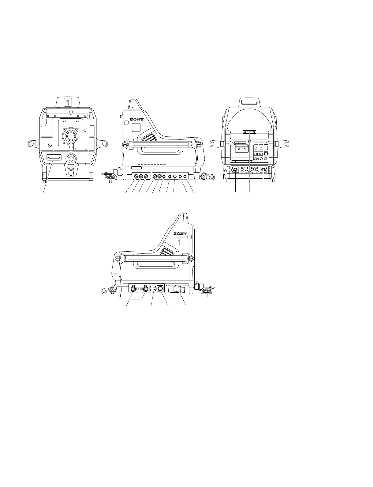
1-2. Connectors and Cables
1-2-1. Connector Input/Output Signals
HDC1000 Connector Layout
!\
24350!'!,89
!- !]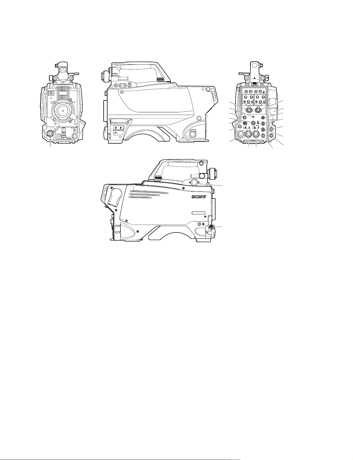
HDC1400/1500/1550/1580 Connector Layout
!=
6
8
!'
!,
9
!]
!. !-
!;
!\
*: HDC1500 only
*
1: There are no connectors on HDC1580.
*
2: There are no connectors on HDC1400/1550.
!-
3
!=
1
0
5
*
2
*1
*2
4
*
7
*1
*1
*2
HDC1000/V1(E)
1-3
Page 12
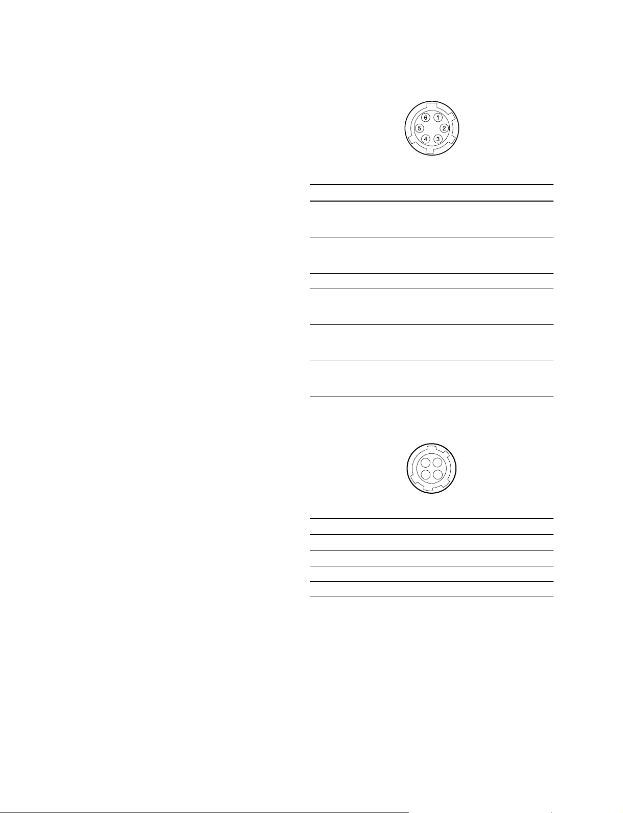
Input/Output Signals
11
1 CCU connector (HDC1000/1400/1500/1580)
11
BTA S-004A/005A/006A compliant 1.485 Gbps serial
HDCU/HDFX connector (HDC1550)
UC: King Triax connector
CE: Fisher Triax connector
88
8 RET CONTROL (6P FEMALE)
88
(External view)
Output Signals
22
2 SDI 1 (HDC1000/1500)
22
HD SDI signal
BTA-S004A compliant
BNC type 75 Z, 0.8 V p-p 1.485 Gbps
33
3 SDI 2 (HDC1000/1500)
33
SDI (HDC1400/1550)
HD SDI signal
BTA-S004A compliant
BNC type 75 Z, 1.0 V p-p
or
SD SDI signal
44
4 TEST OUT
44
BNC type 75 Z, 1.0 V p-p
55
5 PROMPTER OUT (HDC1000/1400/1500/1580)
55
BNC type 75 Z, 1.0 V p-p
66
6 EARPHONE OUT (HDC1400/1500/1550/1580)
66
EARPHONE mini jack
No. Signal I/O Specifications
1 INCOM 1 IN Zi > 10 kZ
MIC-ON/OFF ON : GND
OFF : OPEN
2 INCOM 2 IN Zi > 10 kZ
MIC-ON/OFF ON : GND
OFF : OPEN
3GND ——
4 RET 3-ON/OFF IN Zi > 10 kZ
5 RET 1-ON/OFF IN Zi > 10 kZ
6 RET 2-ON/OFF IN Zi > 10 kZ
99
9 DC OUT (4P FEMALE)
99
ON : GND
OFF : OPEN
ON : GND
OFF : OPEN
ON : GND
OFF : OPEN
1
4
23
77
7 PROMPTER2 OUT (HDC1500)
77
BNC type 75 Z, 1.0 V p-p
Input Signals
55
5 GENLOCK IN (HDC1400/1500/1550/1580)
55
BNC type 75 Z, 1.0 V p-p
(For future use)
55
5 RET IN (HDC1400/1500/1550/1580)
55
BNC type 75 Z, 1.0 V p-p
(For future use)
77
7 Not used
77
1-4
(External view)
No. Signal I/O Specifications
1 UNREG GND —— GND for POWER
2 NC No connection
3 NC No connection
4 UNREG OUT +12 V dc 500 mA (max)
HDC1000/V1(E)
Page 13
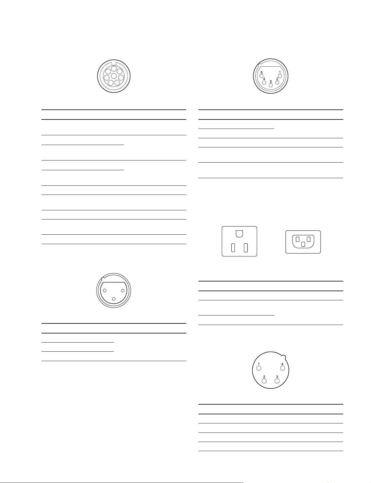
!/!/
!/ REMOTE (8P FEMALE)
!/!/
1
2
8
3
4
!=!=
!= INTERCOM 1/2 (5P FEMALE)
!=!=
7
6
5
(External view)
No. Signal I/O Specifications
for RCP for TRUNK
1 TX (X) TX1 (+) OUT SERIAL DATA OUT
2 TX (Y) TX1 (_) OUT /TRUNK1 DATA OUT
3 TX (X) RX1 (+) IN SERIAL DATA IN
4 TX (Y) RX1 (_) IN /TRUNK1 DATA IN
5 TX-GND —— GND for TX
6 POWER (+) OUT OUT
7 POWER (_) OUT —— GND for UNREG-OUT
8 VIDEO (X) OUT 75 Z, 1.0 V p-p
CHASSIS GND —— CHASSIS GND
!-!-
!- AUDIO IN CH1/CH2 (3P FEMALE)
!-!-
(RS422A)
(for RS-422A)
(for RS-422A)
UNREG +10.5 V to 17 V dc,
200 mA (max)
(SD Video)
(External view)
No. Signal I/O Specifications
1 EXT-INCOM-T (Y) IN _20 dBu (CARBON MIC)
2 EXT-INCOM-T (X) IN _60 dBu (DYNAMIC MIC)
3 GND ——
4 EXT-INCOM- OUT 0 dBu
LEFT (X)
5 EXT-INCOM- OUT 0 dBu
RIGHT (X)
(0 dBu = 0.775 Vrms)
![![
![ AC OUT (HDC1000)
![![
(For service personnel only)
E
LN
LN
UC, J CE
(External view) (External view)
E
21
3
(External view)
No. Signal I/O Specifications
1 AUDIO 1/2 (G) —— _60 dBu, _50 dBu, _40 dBu,
2 AUDIO 1/2 (X) IN _30 dBu, _20 dBu, selectable
3 AUDIO 1/2 (Y) IN High impedance, Balanced
(0 dBu = 0.775 Vrms)
No. Signal I/O Specifications
E GND —— CHASSIS GND
N UTL (C) OUT . AC 100/120 V, 200 VA or
below (UC, J)
L UTL (H) OUT . AC 230 V (CE)
!]!]
!] DC IN (4P MALE)
!]!]
(External view)
No. Signal I/O Specifications
1 EXT_DC (C) —— GND for DC (+)
2 NC No connection
3 NC No connection
4 EXT_DC (H) IN +10.5 to 17 V dc
HDC1000/V1(E)
1-5
Page 14
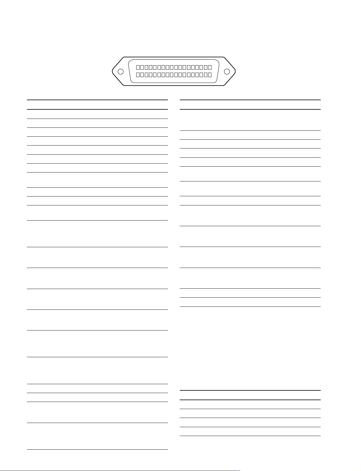
!\!\
!\ LENS (36P FEMALE) (HDC1000)
!\!\
18
36
No. Signal I/O Specifications
1 NC No connection
2 NC No connection
3 NC No connection
4 LENS +12 V OUT +12 V (at 2 A)
5 GND (LENS) —— GND for +12 V (LENS)
6 GND (SIG) —— GND
7 NC No connection
8 LENS-EXT-1 IN
*
2 (LENS SERIAL DATA)
(SERIAL RXD)
9 LENS-EXT-2 IN
10 LENS-EXT-3 IN
*
2
*
2
11 LENS-SERVO OUT ON : GND
OFF : High impedance
12 IRIS-POSI IN Zi > 10 kZ
2 to 7 V
“3.4 ± 0.1 V (F16)”
“6.2 ± 0.1 V (F2.8)”
13 ZOOM-POSI IN Zi > 10 kZ
2 to 7 V
“2 V (WIDE), 7 V (TELE)”
14 RET 1-ON IN Zi > 10 kZ
ON : GND
OFF : High impedance
15 RET 2-ON IN Zi > 10 kZ
ON : GND
OFF : High impedance
16 FOCUS-POSI IN Zi > 10 kZ
2 to 7 V
“2 V (MIN), 7 V (∞ )”
17 IRIS-CONT OUT 2 to 7 V
“3.4 ± 0.1 V (F16)”
“6.2 ± 0.1 V (F2.8)”
Zo < 1 kZ
18 IRIS-AUTO OUT AUTO : GND
/MANU MANU : High impedance
(SERIAL TXD) Zo < 1 kZ
(LENS SERIAL DATA)
19 NC No connection
20 NC No connection
21 LENS R TALLY OUT ON : GND
OFF : High impedance
Zo < 1 kZ
22 LENS-PUPIL-POSI IN Zi > 10 kZ
1 to 4 V
1 V : _7.5d
4 V : +7.5d
1-6
(External view)
No. Signal I/O Specifications
23 RET 3-ON IN Zi > 10 kZ
24 LENS-ADR-0 IN
25 LENS-ADR-1 IN
26 LENS-ADR-2 IN
27 LENS-ADR-3 IN
28 EXT 1-ON OUT ON : GND
29 EXT 2-ON OUT ON : GND
30 F DEM (FAR) IN No connection
31 INCOM 1- IN Zi > 10 kZ
32 INCOM 2- IN Zi > 10 kZ
33 INCOM 1-MIC-ON IN Zi > 10 kZ
34 INCOM 2-MIC-ON IN Zi > 10 kZ
35 F-CONT-SIG OUT No connection
36 F-DEM (NEAR) IN No connection
*
1 Zi > 10 kZ
*
2Zi > 10 kZ
EX1 EX2 EX3 MODE
1 1 1 EXTENDER OFF
1 0 1 EXT-1 (x 1.5) ON
0 1 1 EXT-2 (x 2) ON
0 0 1 EXT-3 (x 2.5) ON
1
19
ON : GND
OFF : High impedance
*
1
*
1
*
1
*
1
OFF : High impedance
OFF : High impedance
ENG/PROD ENG : GND
PRD : High impedance
ENG/PROD ENG : GND
PRD : High impedance
ON : GND
OFF : High impedance
ON : GND
OFF : High impedance
1 : High impedance
+0.5
0 : 0
V
_0
LENS ADRS 0 (low-order bit)
LENS ADRS 3 (high-order bit )
1 : High impedance
0 : 0 ±0.5 V
HDC1000/V1(E)
Page 15

!\!\
!\ LENS (12P FEMALE) (HDC1400/1500/1550/
!\!\
1580)
(External view)
No. Signal I/O Specifications
1 RET VIDEO IN ENABLE : 0 V
ENABLE DISABLE : +5 V or OPEN
2 VTR CTL IN ENABLE : 0 V
3 GND —— GND for UNREG
4 SERVO MA/AT OUT AUTO : +5 V
5 IRIS POSITION OUT +3.4 V (F16) to
6 UNREG OUT +10.5 V to +17 V
7 IRIS POSITION IN +3.4 V (F16) to
8 IRIS AT/MA OUT AUTO IRIS : 0 V
9 EXTENDER IN EX 2 ON : GND
ON/OFF EX 0.8 ON : 30 kZ to GND
10 ZOOM IN WIDE : 2 V
POSITION TELE : 7 V
11 FOCUS POSI IN ∞ : 7 V
(/LENS RX) min. : 2 V
12 (LENS TX) OUT
DISABLE : +5 V or OPEN
MANU : 0 V or OPEN
+6.2 V (F2.8)
+6.2 V (F2.8)
MANUAL IRIS : +5 V
OFF : OPEN
EX 2 ON
EX 0.8 ON
30 kΩ
!;!;
!; VF (25P FEMALE) (HDC1000)
!;!;
13 123456789101112
25
(External view)
No. Signal I/O Specifications
1 VF-Y (X) OUT 1.0 V p-p, Zo = 75 Z
2 VF-GND (Pr) —— GND for VF-Pr (X)
3 VF-Pr (X) OUT 0.7 V p-p, Zo = 75 Z
4 VF-GND (Pb) —— GND for VF-Pb (X)
5 VF-Pb (X) OUT 0.7 V p-p, Zo = 75 Z
6 PEAKING IN 0 to 5 V dc
LEVEL
7 VF-UNREG OUT +10.5 to +20 V
8 VF-UNREG
9 NC No connection
10 S-DATA IN/OUT TTL level
11 TALLY (R)-VF OUT ON : +5 V
12 EFFECT OUT ON : +5 V
13 NC No connection
14 VF-GND (Y) —— GND for VF-Y (X)
15 S-CK OUT TTL level
16 BATT IND OUT ON : +5 V
17 CHASSIS GND —— GND
18 TALLY (G)-VF OUT ON : +5 V
19 GND (UNREG) —— GND for VF-UNREG
20 GND (UNREG)
21 VF-SEL IN BW : 0 V
22 H EXPAND OUT ON : GND
23 NC No connection
24 NC No connection
25 V EXPAND OUT ON : GND
1415161718192021222324
OFF : 0 V
OFF : 0 V
OFF : 0 V
OFF : 0 V
COLOR : +5 V
OFF : +5 V
OFF : +5 V
HDC1000/V1(E)
1-7
Page 16

!;!;
!; VF (20P FEMALE) (HDC1400/1500/1550/1580)
!;!;
!'!'
!' CRANE (12P FEMALE)
!'!'
1
2
10
37
9
8
1211
64
5
(External view)
No. Signal I/O Specifications
1 S-DATA IN/OUT TTL level
2 NC No connection
3 NC No connection
4 SCK OUT TTL level
5 NC No connection
6 NC No connection
7 NC No connection
8 G TALLY OUT ON : 5 V
OFF : GND
9 NC No connection
10 NC No connection
11 NC No connection
12 Y VIDEO OUT 1.0 V p-p, Zo = 75 Z
13 VIDEO GND —— GND for VIDEO
14 Pb VIDEO OUT ±0.35 V p-p, Zo = 75 Z
15 Pr VIDEO OUT ± 0.35 V p-p, Zo = 75 Z
16 NC No connection
17 R TALLY OUT ON : 5 V
OFF : GND
18 NC No connection
19 UNREG GND —— GND for UNREG
20 UNREG OUT +10.5 V to +17 V
(External view)
No. Signal I/O Specifications
1 Pr VIDEO (X) OUT ± 0.35 V p-p, Zo = 75 Z
2 Pb VIDEO (X) OUT ± 0.35 V p-p, Zo = 75 Z
3 NC No connection
for for
RS422A RS232C
4 TX0 (+) TX1 OUT TRUNK Data out
5 TX0 (_) TX0 OUT
6 RX0 (_) RX0 IN TRUNK Data in
7 RX0 (+) RX1 IN
8 GND (VIDEO) —— GND for VIDEO
9 Y VIDEO (X) OUT 1.0 V p-p, Zo = 75 Z
10 GND —— GND for SCL/SDA
11 SCL EXT-VF OUT TTL level
12 SDA EXT-VF IN/OUT TTL level
1-8
HDC1000/V1(E)
Page 17
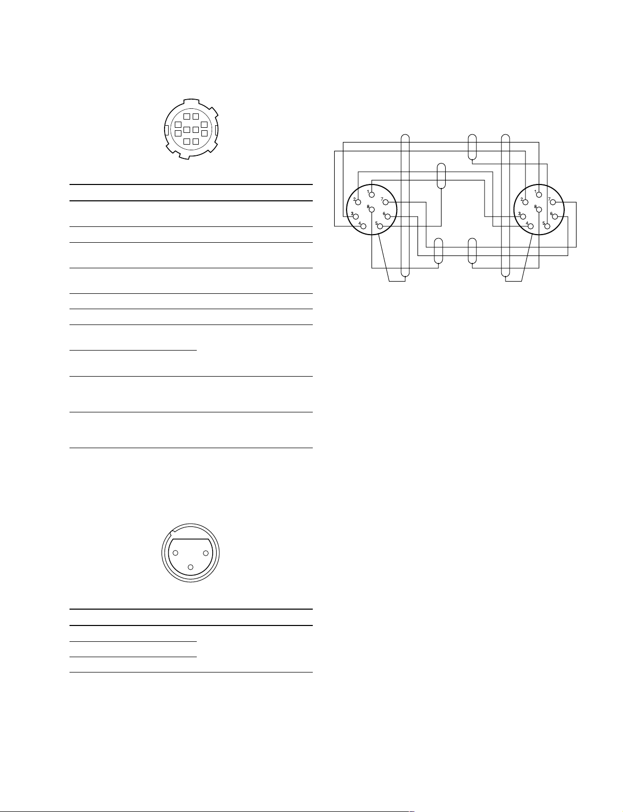
!,!,
BrownBrown
Brown
Red
Red
White
White
White
Orange
Black
— 8P CONNECTOR (MALE) —
(WIRING SIDE)
!, TRACKER (10P FEMALE)
!,!,
1-2-2. Wiring Diagrams for Cables
81
27
10 9
63
54
(External view)
No. Signal I/O Specifications
1 TRACKER OUT TRACKER RECEIVE/PGM
LEFT _20 dBu unbalanced
2 GND (TALK) —— GND for TRACKER TALK
3 GND (RECEIVE/ —— GND for RECEIVE/PGM/TL
PGM/TL)
4 TRACKER RIGHT OUT TRACKER RECEIVE/PGM
_20 dBu unbalanced
5 UNREG OUT +12 V (+10.5 to +17.0 V)
6 GND (UNREG) —— GND for UNREG
7 TRACKER IN TRACKER TALK
TALK (X) 0 dBu /_20 dBu
8 TRACKER IN High impedance balanced
TALK (Y)
9 G TALLY OUT ON : GND
OFF : High impedance
(Open collector)
10 R TALLY OUT ON : GND
OFF : High impedance
(Open collector)
(0 dBu = 0.775 Vrms)
CCA-5 Cable
!.!.
!. MIC 1 IN (3P FEMALE) (HDC1400/1500/1550/
!.!.
1580)
21
3
(External view)
No. Signal I/O Specifications
1 MIC 1 (G) —— _60 dBu, _50 dBu, _40 dBu,
2 MIC 1 (X) IN _30 dBu, _20 dBu, selectable
3 MIC 1 (Y) IN High impedance, Balanced
HDC1000/V1(E)
(0 dBu = 0.755 Vrms)
1-9
Page 18

1-2-3. Connection Connectors/Cables
Connection made with the connector panels during installation or service, should be made with the connectors/
complete cable assemblies specified in the following list,
or equivalent parts.
Indication Connection connector/cable
TEST OUT 1-569-370-12 Plug, BNC
PROMPTER OUT
SDI 1/2
(BNC)
AUDIO IN CH1/CH2 1-508-084-00 XLR, 3P Male or
MIC 1 IN ITT Cannon XLR-3-12C equivalent
(3P FEMALE)
RET CONTROL 1-560-078-00 Plug, 6P Male or
(6P FEMALE) HIROSE HR10-7PA-6P equivalent
DC OUT 1-566-425-11 Plug, 4P Male or
(4P FEMALE) HIROSE HR10A-7P-4P equivalent
INTERCOM 1/2 1-508-370-11 XLR, 5P Male or
(5P FEMALE) ITT Cannon XLR-5-12C equivalent
DC IN 1-508-362-00 XLR, 4P Female or
(4P MALE) ITT Cannon XLR-4-11C equivalent, or
CRANE 1-819-261-11 Connector,
(12P FEMALE) Round Type 12P
REMOTE . 1-766-848-11 Plug, 8P Male or
(8P FEMALE) CCA-5 cable assembly
TRACKER 1-506-522-12 Connector,
(10P FEMALE) Round Type 10P
*1: Use of REMOTE cable enables to monitor video signals. (The pin 8 is
available for the video signal line.)
The down-converted SD signal is output.
*2: If using a cable of length different from a standard product, contact your
local Sony Sales Office/Service Center.
n
*3: The pin 8 of CCA-5 cable is GND (ground).
The pin 8 of REMOTE cable is not GND (ground).
Cable assembly 1-551-577-00
(Supplied with AC-550/550CE)
(CCA-5-10 (10 m) /CCA-5-3 (3 m))
*2 *3
(option)
. REMOTE cable 1-783-372-11
(supplied with RM-B150, 10 m)
*1 *2 *3
1-2-4. Note in Connecting CCU Connector
(HDC1000/1400/1500/1580)
It is recommendable to clean the optical contact portions
mentioned below before connecting this unit to the camera
control unit.
. CCU connector of this unit
. Camera connector of the camera control unit
. Optical/Electrical cable
For details on a cleaning method, refer to Section 1-8
“Cleaning of Connector/Cable”.
1-10
HDC1000/V1(E)
Page 19
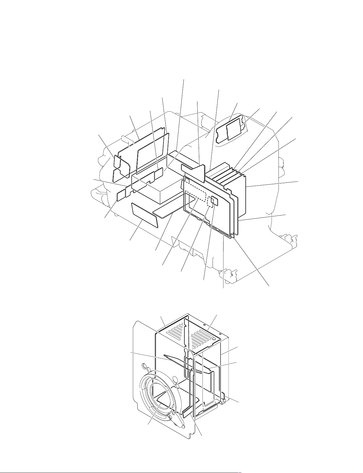
1-3. Location of Printed Circuit Boards
HDC1000
SWITCHING REGULATOR
AT-166
SW-1233
CN-2671
CN-2609
DC-DC COVERTER
LE-291
LE-309
AT-163
AU-298
CN-2608
CN-2603 (for UCJ)
CN-2603B (for CE)
CN-2671
CN-2606
CN-2607
CN-2604
CN-2605
CN-2602
SDI-84
DAP-33
VDA-63
MB-1060
DPR-265
HDC1000/V1(E)
BI-175
BI-175
PA-317
TG-243
DR-528
BI-175
CN-2579
CN-2578
1-11
Page 20
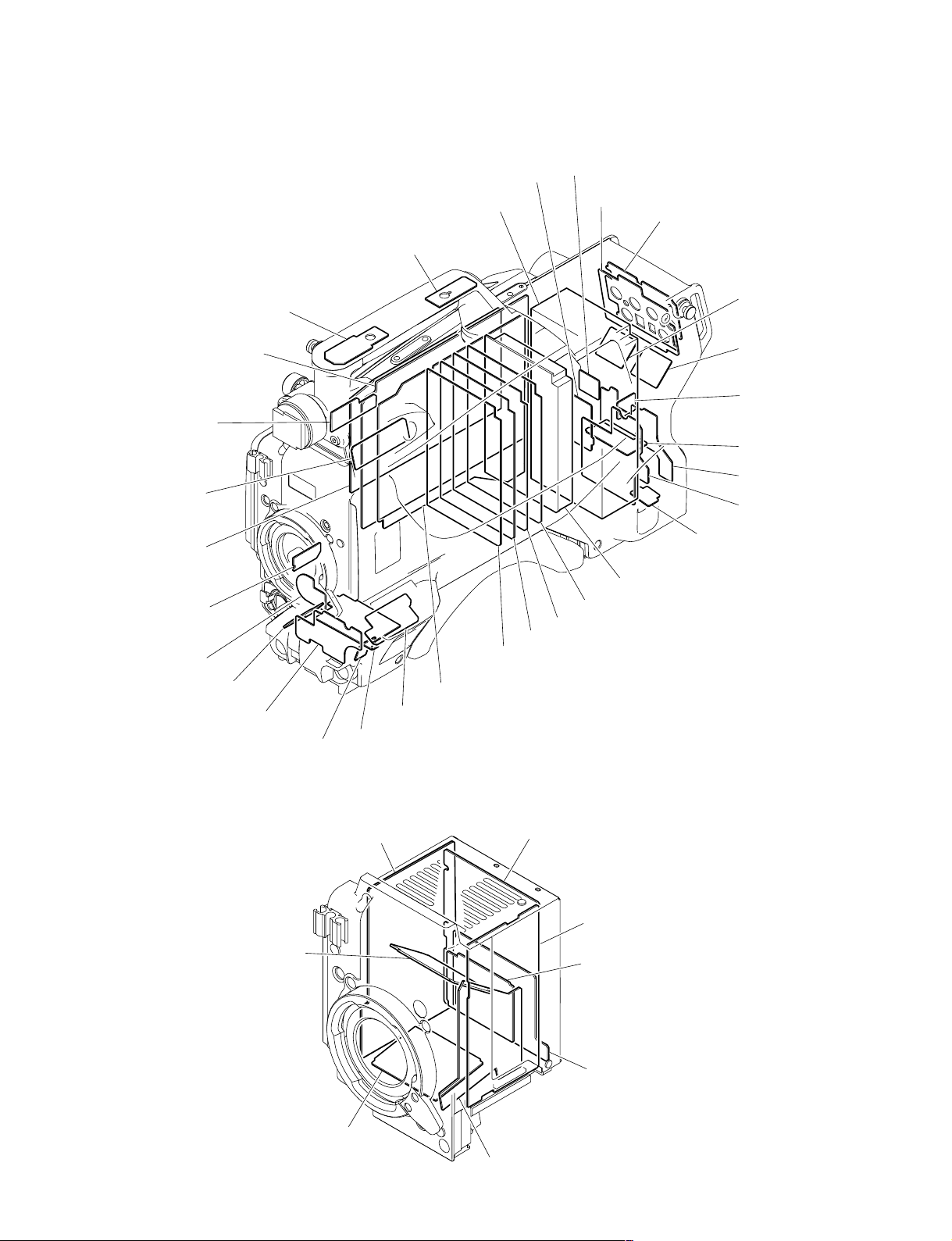
HDC1400/1500/1580
SW-1236
DPR-265 (HDC1400/1500)
DPR-265C (HDC1580)
CN-2614B
SW-1237
SDI-84 (HDC1500)
SDI-84C (HDC1400/1580)
SW-1238
CN-2615
SWITCHING REGULATOR
LE-308
CN-2620
VDA-63
CN-2622
SW-1241 (HDC1400, HDC1500 (SY))
SW-1241B (HDC1500 (CE)/HDC1580)
SW-1273
CN-2618
CN-2618
CN-2640
SW-1242
CN-2619
CN-2621
CN-2623
DC-DC COVERTER
AT-163
AU-298
DAP-33
CN-2616
SW-1239
SW-1245
PA-317 (HDC1400/1500)
PA-317C (HDC1580)
BI-175
CN-2617
BI-175
MB-1059
SW-1240
TG-243 (HDC1500)
TG-243B (HDC1400)
TG-243C (HDC1580)
DR-528
BI-175
CN-2579
1-12
CN-2578
HDC1000/V1(E)
Page 21

HDC1550
DPR-265B
TR-136
CN-2614
SW-1237
SW-1238
CN-2615
SW-1236
SWITCHING REGULATOR
LE-308
MX-109
FL-338
CN-2620
DAP-33
VDA-63
CN-2622
SW-1241 (for UC)
SW-1241B (for CE)
SW-1273
FL-337
CN-2618
CN-2618
CN-2640
SW-1242
CN-2619
CN-2621
CN-2623
DC-DC COVERTER
AT-163
AU-298
CN-2616
SW-1239
SW-1245
BI-175
CN-2617
BI-175
PA-317
MB-1059
SW-1240
TG-243
DR-528
BI-175
CN-2579
CN-2578
HDC1000/V1(E)
1-13
Page 22

1-4. Opening/Closing the Side Panel
HDC1000
1. Unscrew the two lock screws of the side panel.
2. While sliding the safety lock toward the lens, open the
side panel by holding the handle.
3. Close the side panel and tighten securely the lock
screws of the side panel.
n
Closing the side panel brings the safety lock to an
automatic locking.
Safety lock
Handle
HDC1550
1. Unscrew the nine screws as shown in the figure, then
open the inside panel and outside panel.
2. Release the hanging band (FRONT) and hanging band
(REAR) from the inside panel.
3. Disconnect the harness from the connector (CN1) on
the SW-1240 board, and remove the inside panel.
4. Disconnect the harness from the connector (CN3) on
the FL-337 board, and remove the outside panel.
Outside panel
Screws
FL-337 board
CN3
Switching regulator
Hanging Band
(REAR)
Lock screws of the side panel
HDC1400/1500/1580
1. Unscrew the nine screws as shown in the figure, then
open the inside panel and outside panel.
2. Release the hanging band (FRONT) and hanging band
(REAR) from the inside panel.
3. Disconnect the harness from the connector (CN1) on
the SW-1240 board, and remove the inside panel.
4. Disconnect the harness from the switching regulator
connector, and remove the outside panel.
Outside panel
Screws
Switching regulator
Hanging Band
(REAR)
Hanging Band
(FRONT)
SW-1240 board
Inside panel
CN1
Screws
5. Reinstall the panels by reversing the steps above.
Hanging Band
(FRONT)
SW-1240 board
Inside panel
CN1
Screws
5. Reinstall the panels by reversing the steps above.
1-14
HDC1000/V1(E)
Page 23

1-5. Switch Settings
AT-163 Board
ABC
1
S1
2
3
4
5
AT-163 BOARD (SIDE A)
Ref. No. Name Description Factory setting
S1-1 Reserve Not used (Fixed to OFF) OFF
S1-2 All Preset FRAM clear OFF
S1-3 Reserve Not used (Fixed to OFF) OFF
S1-4 Firmware Load Forcibly upgrading of firmware OFF
AT-166 Board (HDC1000)
ABC
1
2
S1
AT-166 BOARD (SIDE B)
Ref. No. Name Description Factory setting
S1-1 ICE Not used (Fixed to OFF) OFF
S1-2 WRITER Switch ON for software upgrading OFF
S1-3 TEST1 Not used (Fixed to OFF) OFF
S1-4 TEST2 Not used (Fixed to OFF) OFF
HDC1000/V1(E)
1-15
Page 24

AU-298 Board
D
S3
C
B
A
S1 S2
123
AU-298 BOARD (SIDE A)
Ref. No. Name Description Factory setting
S1 Reserve Not used (Fixed to NORM) NORM
S2 Reserve Not used (Fixed to NORM) NORM
S3-1 AB POWER MIC1 Switch ON to supply +12 V for MIC POWER to the OFF
S3-2 AB POWER MIC2 Switch ON to supply +12 V for MIC POWER to the OFF
microphone connected to the AUDIO IN CH1 connector.
microphone connected to the AUDIO IN CH2 connector.
DPR-265 Board (HDC1000/1400/1500/1550)
DPR-265C Board (HDC1580)
AB CDEF
5
4
3
2
1
S13
DPR-265/265C BOARD (SIDE A)
Ref. No. Name Description Factory setting
S13 Reserve Not used (Fixed to OFF) OFF
1-16
HDC1000/V1(E)
Page 25

SDI-84 Board (HDC1000/1500)
SDI-84C Board (HDC1400/1580)
S201
F
S202
A
1
2
3
4
BC
D
E
SDI-84/84C BOARD (SIDE A)
Ref. No. Name Description Factory setting
HDC1000/1500 HDC1400/1580
S201-1 TEST Not used (Fixed to OFF) OFF OFF
S201-2 PROMPTER2 OUT Switch ON for PROMPTER2 ON (active) OFF
S201-3 VBS RET IN Switch ON for VBS RET OFF (non-active) OFF
S201-4 to 8 Reserve Not used (Fixed to OFF) OFF OFF
S202 LD RESET Not used (Fixed to OFF) OFF OFF
TG-243 Board (HDC1000/1500)
TG-243B Board (HDC1400)
TG-243C Board (HDC1580)
C
B
S1
A
12
TG-243/243C BOARD (SIDE A)
Ref. No. Name Description Factory setting
S1 Test Not used OFF
HDC1000/V1(E)
1-17
Page 26

TR-136 Board (HDC1550)
A
S1
1
2
3
B
C
D
TR-136 BOARD (SIDE A)
Ref. No. Name Description Factory setting
S1-1 When this switch is set to ON, the multiformat OFF
color-bar signal is output from the built-in video
test signal generator.
S1-2 Spare (not used) OFF
S1-3
S1-4 When this switch is set to ON, the 400 Hz sine wave OFF
is output from the built-in audio test signal generator.
S1-5 When this switch is set to ON, the 1 kHz sine wave OFF
is output from the built-in audio test signal generator.
S1-6 to S1-8 Spare (not used) OFF
1-18
HDC1000/V1(E)
Page 27

1-6. Notes for Replacing Parts
There are two kinds of types in the parts below used in this unit.
. Flexible card wires (Refer to Section 1-6-1.)
. Boards (Refer to Section 1-6-2.)
. Connectors on the board (for flexible card wires) (Refer to Section 1-6-3.)
When replacing the parts above, be sure to follow the instructions described in “1-6-1. Notes for Replacing the Flexible
Card Wire”, “1-6-2. Notes for Replacing the Board”, and “1-6-3. Notes for Replacing the Connector on the Board”.
Be sure to use the specified parts. Using un-specified parts causes the change in the characteristics of this unit and the unit
does not work properly.
Spare parts are listed in the spare parts list of “Spare Parts” Section. In the spare parts list, (GOLD) or (SILVER) is put
after each part name to distinguish two kinds of types (gold and silver).
1-6-1. Notes for Replacing the Flexible Card Wire
When replacing the flexible card wires listed below, confirm the conductive (terminal) part color of the flexible card wires
and follow the procedure below.
1. Replace the flexible card wire with a flexible card wire whose conductive part is gold when the conductive part of a
flexible card wire is gold.
n
For the board on which a connector whose contact surface is gold is used, “G” is put after the board name by silkscreen printing or a “G” seal is attached to the empty space on the board. Example: AT-166G
2. Replace the flexible card wire with a flexible card wire whose conductive part is silver when the conductive part of a
flexible card wire is silver. In this case, silk “G” or a “G” seal is not put on the board name.
When the conductive part is gold (HDC1000)
Board Flexible card wire Board
Pin Gold : Parts No.
AT-166G 30 1-831-132-11 SW-1233G
CN-2609G 30 1-831-118-11 MB-1060G
CN-2579G 40 1-831-658-11 PA-317G
CN-2579G 30 1-831-656-11 DR-528G
DR-528G 45 1-831-659-11 TG-243G
When the conductive part is gold (HDC1500/1550)
Board Flexible card wire Board
Pin Gold : Parts No.
CN-2619G 40 1-831-662-11 MB-1059G
CN-2621G 36 1-831-663-11 MB-1059G
MB-1059G 36 1-831-661-12 SW-1273G
CN-2579G 40 1-831-658-11 PA-317G
CN-2579G 30 1-831-656-11 DR-528G
DR-528G 45 1-831-659-11 TG-243G
When the conductive part is silver (HDC1000)
Board Flexible card wire Board
Pin Silver : Parts No.
AT-166 30 1-823-558-11 SW-1233
CN-2609 30 1-757-644-11 MB-1060
CN-2579 40 1-830-485-11 PA-317
CN-2579 30 1-830-735-11 DR-528
DR-528 45 1-830-484-11 TG-243
When the conductive part is silver (HDC1500/1550)
Board Flexible card wire Board
Pin Silver : Parts No.
CN-2619 40 1-830-483-11 MB-1059
CN-2621 36 1-830-752-11 MB-1059
MB-1059 36 1-830-482-11 SW-1273
CN-2579 40 1-830-485-11 PA-317
CN-2579 30 1-830-735-11 DR-528
DR-528 45 1-830-484-11 TG-243
HDC1000/V1(E)
1-19
Page 28

1-6-2. Notes for Replacing the Board
Replace the board with a board of the same number as the spare part number of the board to be removed
when replacing a board.
Example: A spare part number is put on the board.
A-1159-990-A
A spare part number is put on side A or B of the board
by silk-screen printing or a spare part code label (spare
part number) is attached on side A or B.
Spare part number
1-6-3. Notes for Replacing the Connector on the Board
There are two types of connectors for the flexible card wire mounted on the board used in this unit.
Distinguish them in the procedure below when replacing these connectors.
1. The contact surface of the connector used for a board is gold when the conductive part of a flexible
card wire is gold.
In a spare parts list, (GOLD) is put after the part name.
2. The contact surface of the connector used for a board is silver when the conductive part of a flexible
card wire is silver.
In a spare parts list, (SILVER) is put after the part name.
1-6-4. Notes for HDC1400 and HDC1580
The contact of flexible card wire used in the HDC1400 and HDC1580 is gold-plated. Therefore, when the
flexible card wire needs to be replaced, use the part listed below.
Also, for the board on which a connector whose contact surface is gold is used, "G" is put after the board
name by silkscreen printing or a "G" seal is attached to the empty space on the board. Example: CN2619G
Board Flexible card wire Board
Pin Gold : Parts No.
CN-2619G 40 1-833-557-11 MB-1059G
CN-2621G 36 1-831-663-11 MB-1059G
MB-1059G 36 1-831-661-12 SW-1273G
CN-2579G 40 1-831-658-11 PA-317CG
CN-2579G 30 1-831-656-11 DR-528G
DR-528G 45 1-831-659-11 TG-243CG
*1, *3: For HDC1580
*2, *4: For HDC1400
1-20
*1
/PA-317G
*3
/TG-243BG
*2
*4
HDC1000/V1(E)
Page 29
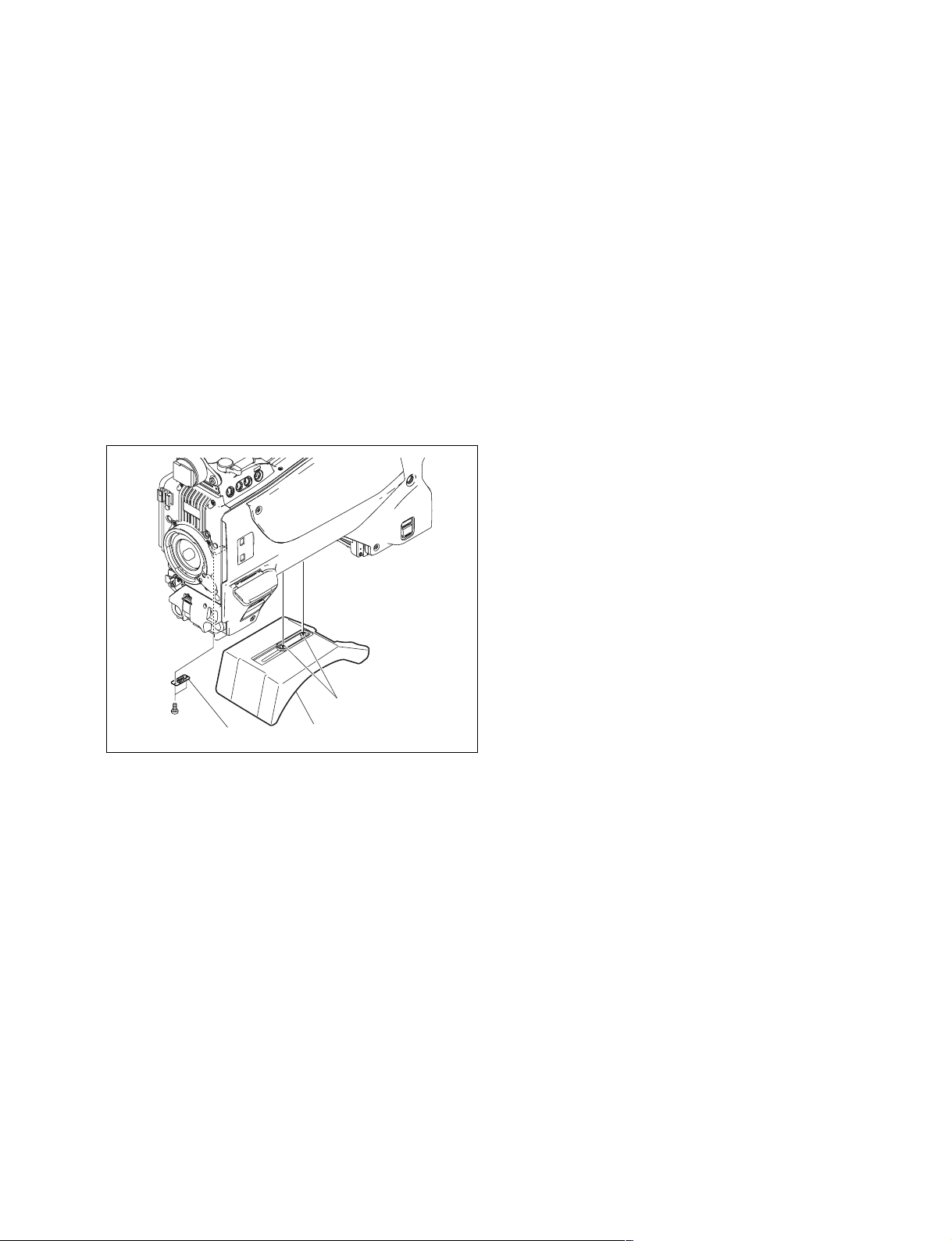
1-7. Cleaning the Vent Portion of the
Fan (HDC1400/1500/1550/1580)
The ventilate bracket for preventing from dust is attached
in the vent portion of the fan. Clean the ventilate bracket
every two or three months. Clogging may cause the
temperature increases inside the camera and result in a
trouble.
1. Loosen the two screws with stopper, and remove the
shoulder pad assembly.
2. Remove the two screws, and remove the ventilate
bracket.
3. Remove dust on the ventilate bracket with a vacuum
cleaner.
Precision
P2 x 4
Ventilate bracket
Screws with stopper
Shoulder pad assembly
HDC1000/V1(E)
1-21
Page 30
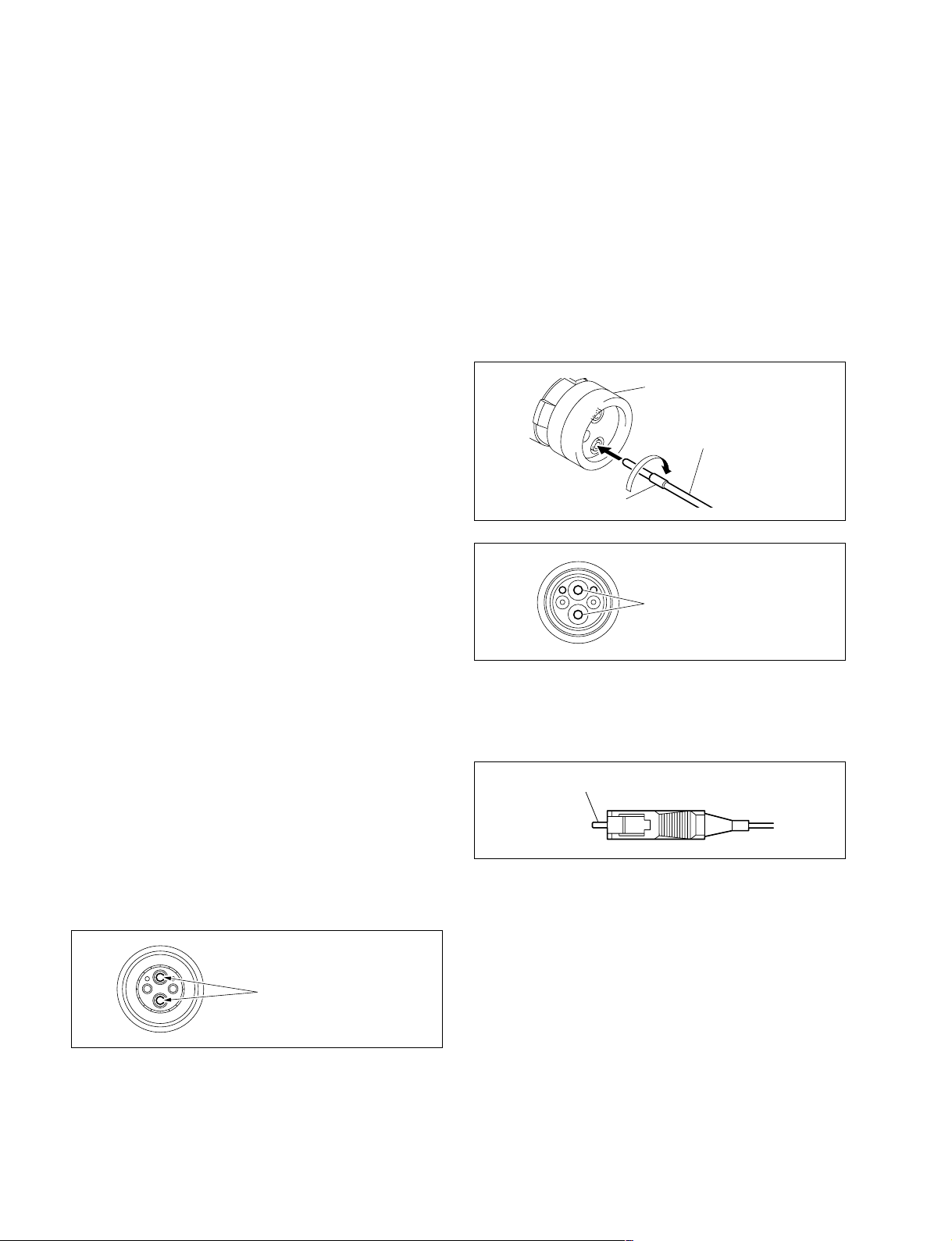
1-8. Cleaning of Connector/Cable
(HDC1000/1400/1500/1580)
The photo receptive condition of the optical connector can
be checked at OPTICAL CONDITION of the DPR board
of the camera control unit.
When lit in green: Normal (_17 dBm or above)
When lit in yellow: Normal (_17 to _20 dBm)
When lit in red: Abnormal (Less than _20 dBm)
When lit in red, be sure to clean the optical contact portions.
When lit in yellow, cleaning is recommended.
The attenuation of the photo-receptive level may cause
transmission error between the camera and HDCU. In the
case of attenuation, be sure to clean optical contact portions proceeding as follows. The optical contact portions
exist in the optical connector on the camera or HDCU, and
in the optical/electrical cables.
1-8-1. When the Optical Connector Cleaner
(Commercially Available) is Available
[Female connector]
1. Insert the optical connector cleaner straight. Ensure
that it is held straight when inserting.
2. Apply sufficient pressure (approximately 600 g to 700
g) to ensure that the optical contact is a little depressed.
3. While pressing the optical connector cleaner against
the tip of the optical contact, rotate the optical connector cleaner by 4 to 5 turns clockwise. Holding the
optical connector cleaner at around its support facilitates to apply the pressure.
Alignment sleeve
Optical connector cleaner
Support
Tools required
. Optical connector cleaner (commercially available)
Product name: CLETOP®
14100402 or 14100403 (stick type) or equivalent
14100402: 2.0 mm
14100403: 2.0/2.5 mm double ended
m
. Alcohol is not necessary during cleaning.
. Number of possible wipes is one cleaning per a piece.
Do not reuse it.
Cleaning procedure
[Male connector]
Clean the tip of the white optical contacts using the optical
connector cleaner.
Optical contacts (white)
Optical contacts (white)
[Connector]
Clean the tip of the white optical contacts using the optical
connector cleaner.
Optical contacts (white)
1-22
HDC1000/V1(E)
Page 31
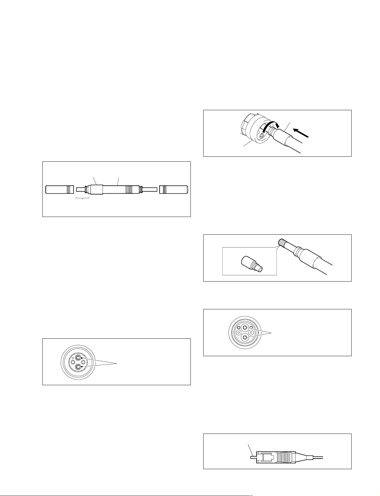
1-8-2. When the Optical Connector Cleaner
(Commercially Available) is not
Available
Tools required
. Alignment sleeve remover HC-001
(for female connector)
Sony P/N: J-6480-010-A
n
Insert the shorter nose end when removing/installing the
alignment sleeve.
Grasp not the shock absorber portion of the remover but
the handle in use.
[Female connector]
The optical contacts for female connector are in an unexposed state. In cleaning, it is necessary to be exposed by
removing the alignment sleeve in advance. Proceed as
follows.
1. Insert the alignment sleeve remover into the alignment
sleeve in the straight line and turn it clockwise.
Alignment sleeve remover
Alignment sleeve
Shock absorber portion Handle
Insert the shorter nose end
. Alcohol (commercially available)
. Cotton swabs (commercially available)
n
Use a cotton swab whose diameter is about 4 mm.
If a cotton swab whose diameter exceeds 5 mm is used,
the cotton swab cannot be inserted into the end of the
connector and the tip of the optical contact cannot be
cleaned.
Cleaning Procedure
[Male connector]
Clean the tip of the white optical contacts by a cotton swab
moistened with alcohol.
2. When the turn stops, pull out the remover in the
straight line forcedly.
n
The alignment sleeve can be removed/reinstalled with
the sleeve itself attached to the tip of the remover.
Great care should be taken so as not to lose or damage
the alignment sleeve.
(Alignment sleeve: Sony P/N 9-980-074-01)
Alignment sleeve
3. Clean the tip of the white optical contacts by a cotton
swab moistened with alcohol.
Optical contacts (white)
HDC1000/V1(E)
Optical contacts (white)
4. Insert the remover with the alignment sleeve attached
to its tip, and push it until it clicks.
5. Rotate the remover counterclockwise to install the
alignment sleeve, and extract the remover.
[Connector]
Clean the tip of the white optical contacts by a cotton swab
moistened with alcohol.
Optical contacts (white)
1-23
Page 32
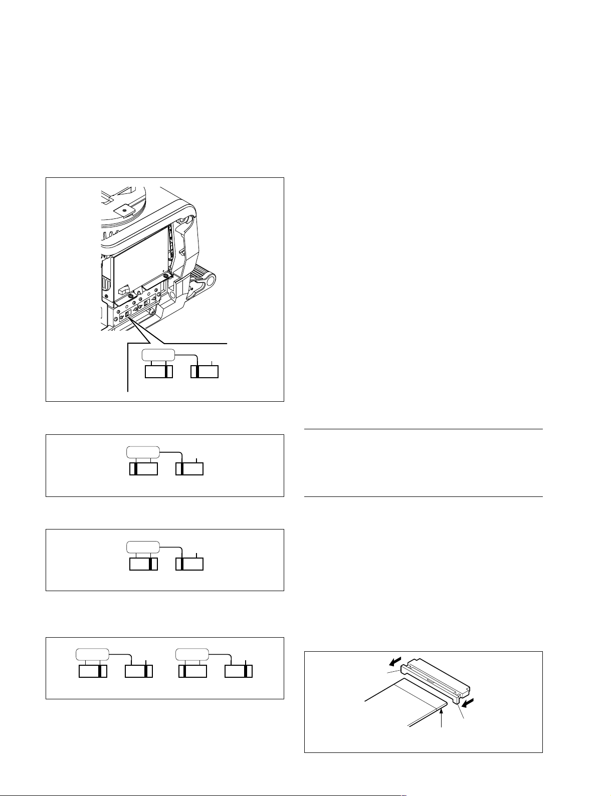
1-9. Setting the Utility Out Voltage
(HDC1000)
Set the utility out voltage in accordance with the voltage of
peripheral devices when they are connected to the camera.
The setting of the utility out voltage can be made by the
combination of the switches 1 and 2 in the figure.
100V120V 230V
12
1-10. Notes on Flexible Card Wire
1-10-1. Disconnecting/Connecting Flexible
Card Wire
The flexible card wires are used between the boards of
HDC1000/1400/1500/1550/1580. Take care not to bend
forcedly these flexible card wires. This shortens the wire life.
HDC1000
Between CN-2579 and DR-528
Between CN-2579 and PA-317
Between TG-243/243C and DR-528
Between AT-166 and SW-1233
Between MB-1060 and CN-2609
HDC1400/1500/1550/1580
Between CN-2579 and DR-528
Between CN-2579 and PA-317/317C
Between TG-243/243B/243C and DR-528
Between MB-1059 and CN-2619
Between MB-1059 and CN-2621
Between MB-1059 and SW-1273
Between MX-109 and TR-136 (HDC1550 only)
. When setting to 100 V, set as shown below.
100V120V 230V
12
. When setting to 120 V, set as shown below.
100V120V 230V
12
. When setting to 230 V, set as shown below.
Setting of the switch 1 is not required.
100V120V 230V
12
100V120V 230V
12
Type-A
Disconnecting
Slide portions A in the direction of the arrow to unlock and
pull out the flexible card wire.
Connecting
m
. Be careful not to insert the flexible card wire obliquely.
. Check that the conducive surface of the flexible card
wire is not soiled with dust.
1. Slide portions A in the direction of the arrow and
insert the flexible card wire with the conductive
surface downward as far as it will go.
2. Slide portions A in the reverse direction to lock.
A
1-24
A
Conductive
surface
HDC1000/V1(E)
Page 33
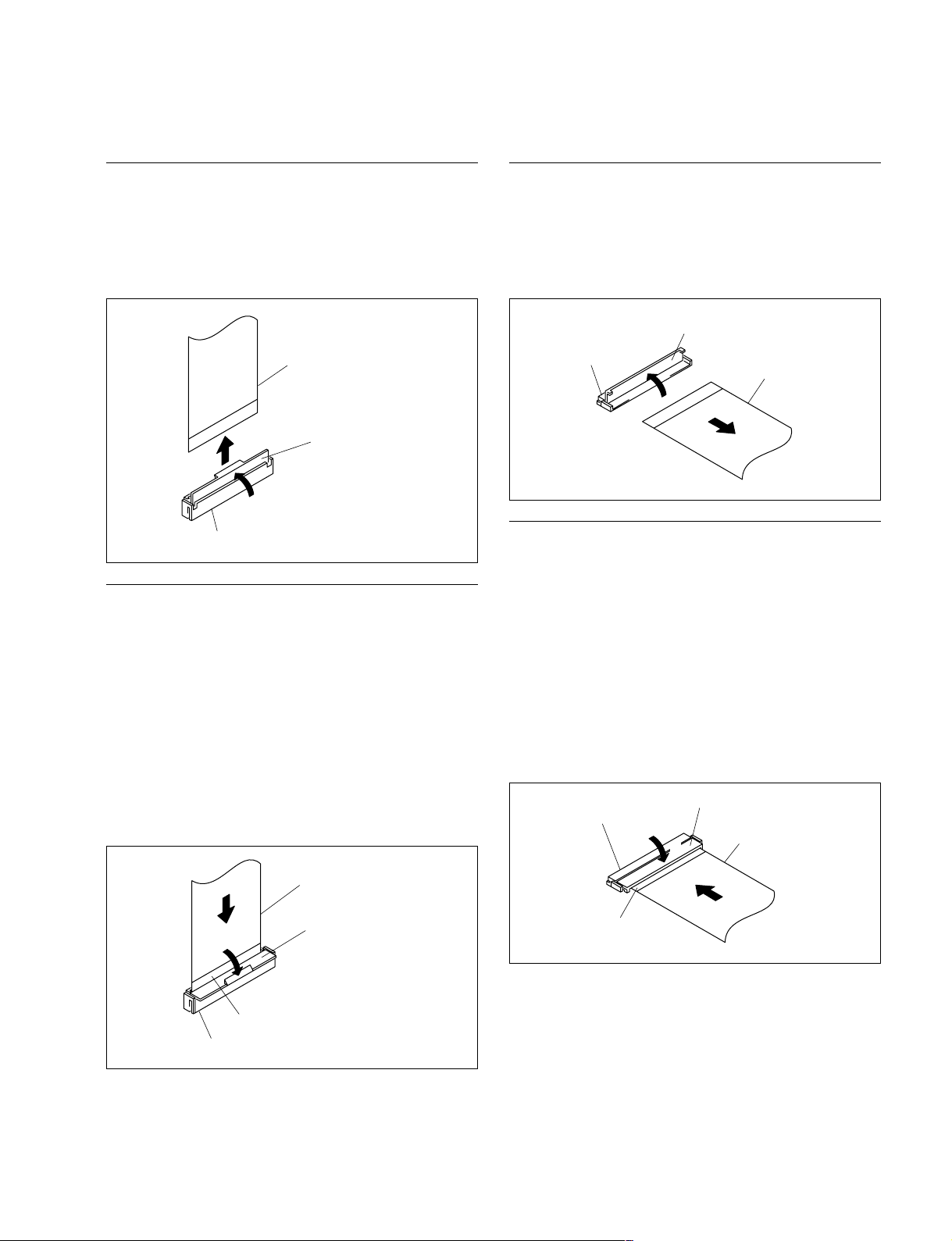
Type-B
Type-C
Disconnecting
1. Open the connector latch in the direction of arrow A to
release the lock.
2. Remove the flexible card wire in the direction of arrow
B.
Flexible card wire
B
A
Connector
Connector latch
Connecting
m
. Be careful not to insert the flexible card wire obliquely.
. Check that the conducive surface of the flexible card
wire is not soiled with dust.
1. Hold the flexible card wire with its insulating surface
facing to the front, and insert it in the direction of
arrow A.
2. Close the connector latch in the direction of arrow B to
lock it.
Flexible card wire
Disconnecting
1. Open the connector latch in the direction of arrow A to
release the lock.
2. Remove the flexible card wire in the direction of arrow
B.
Connector latch
Connector
A
Flexible card wire
B
Connecting
m
. Be careful not to insert the flexible card wire obliquely.
. Check that the conducive surface of the flexible card
wire is not soiled with dust.
1. Hold the flexible card wire with its insulating surface
facing upward, and insert it in the direction of arrow
A.
2. Close the connector latch in the direction of arrow B to
lock it.
Connector latch
Connector
Flexible card wire
B
A
HDC1000/V1(E)
A
Connector
B
Insulating
surface
Connector latch
Insulating
surface
1-25
Page 34
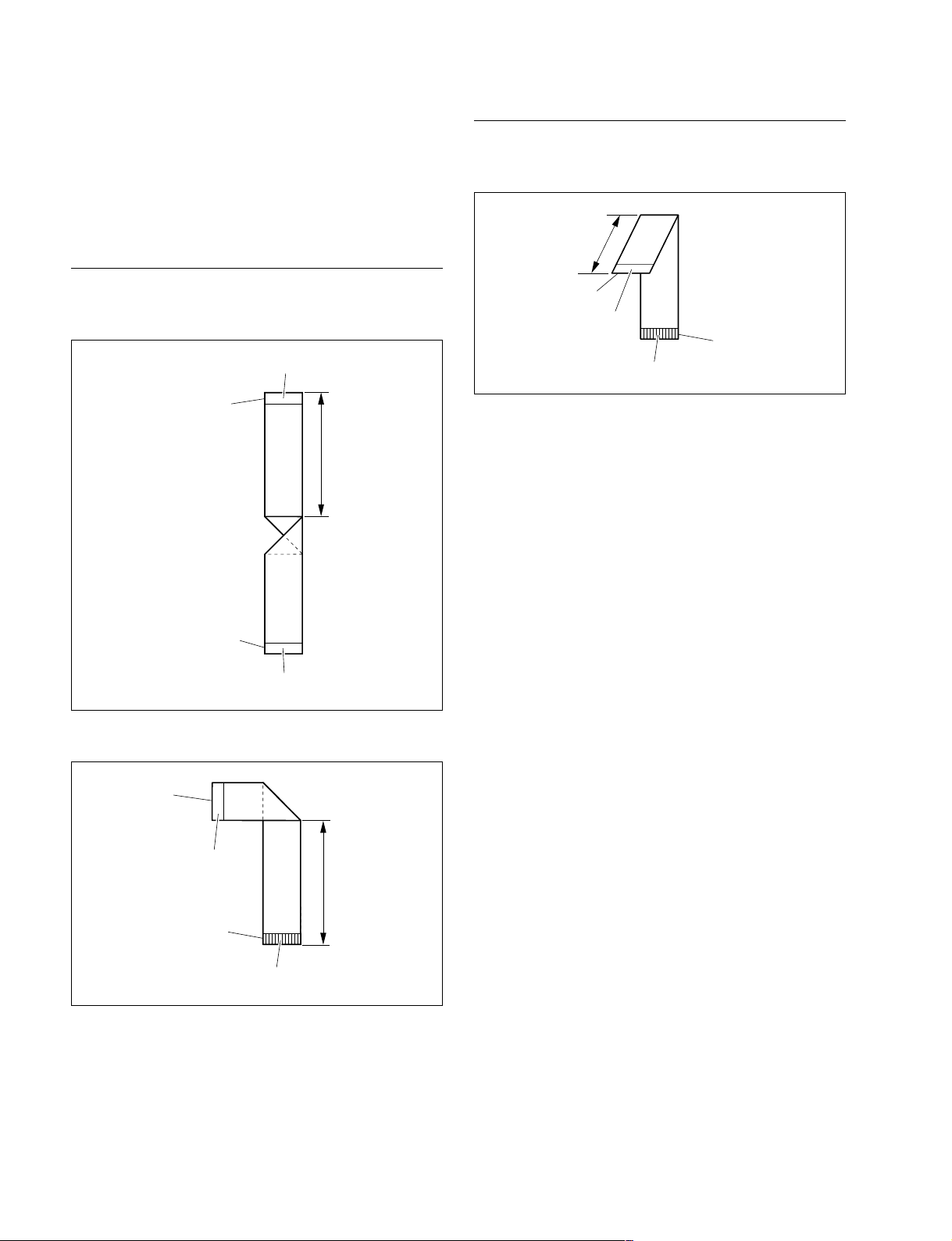
1-10-2. Forming of the Flexible Card Wire
HDC1550
If using a new flexible card wire, be sure to fold it by hand
it as shown in the figure before installation.
n
Never fold it back after being formed once.
HDC1000
. MB-1060 board CN6 ↔ CN-2609 board CN3
Insulating surface
MB-1060(CN6)
55
. MX-109 board CN1 ↔ TR-136 board CN2
30
TR-136(CN2)
Insulating
surface
Conductive surface
MX-109(CN1)
unit : mm
CN-2609(CN3)
Insulating surface
unit : mm
. MB-1059 board CN11 ↔ SW-1273 board CN1
MB-1059(CN11)
Insulating
surface
SW-1273(CN1)
Conductive surface
100
unit : mm
1-26
HDC1000/V1(E)
Page 35

1-11. Notes on Replacement of Circuit
Board
1-11-3. Adjustment and Setting Items when
Replacing AT-163 Board
1-11-1. Description on EEPROM Data
The table below gives the stored data of EEPROM
(FRAM) on every printed circuit board.
Board Ref. No. Stored data
AT-163 IC133, IC139, Board adjustment data (VDA,
IC141, IC142 DPR), and paint data
IC403 PLD data
TG-243/247 IC6 PLD data
IC39 RPN compensation data
IC40 CCD adjustment data
AU-298 IC11, IC12, IC13 Status of the stand by intercom
SDI-84 IC212 PLD data
(HDC1000/1500)
TR-136 IC504 PLD data
(HDC1550)
VDA-63 IC109 PLD data
DAP-33 IC202 PLD data
m
. When the replacement is needed, remove the IC attached
to the former board and replace it to the new board.
. The IC listed above cannot be replaced because it is the
EEPROM that is the storing data inherent in the board.
The part number listed in “Spare Parts” is for EEPROM
which is not programmed. If replacement is needed,
contact your local Sony Sales Office/Service Center.
1-11-2. Adjustment after Replacement of
Board
Camera settings and various files are stored in the AT-163
board. When the AT-163 board is replaced, the contents of
the reference file, scene file, lens file, and operator file are
lost. Store these files in a Memory Stick or other storage
media beforehand, and then replace the AT-163 board.
Since the OHB file is stored in the CCD unit, it is not lost
by the replacement of the board.
Replacement
1. Store the reference file, scene file, and operator file in
the memory stick. (Refer to “Section 4. File System.”)
2. Install the latest version of the firmware programs.
(Refer to “Section 1-13. Upgrading the Software.”)
3. Execute ALL PRESET on the REFERENCE page of
the FILE menu, and then perform “reference store.”
(Refer to “Reference File” in “Section 4. File
System.”)
n
If ALL PRESET is not executed, the intercom panel
may not work correctly.
4. For HDC1000, set the destinations of the intercom
with the SERVICE menu. (Refer to “INTERCOM” in
“Section 5. Setup Menu.”)
5. Adjust the adjustment items of the VDA and DPR
boards. (Refer to “Section 3. Electrical Alignment.”)
6. Install the stored reference file, scene file, and operator
file, if any, and then perform “Level auto setup.”
(Refer to “Reference File” in “Section 4. File
System.”)
When replacing or repairing the board, perform the
electrical alignment referring to Section 3.
HDC1000/V1(E)
1-27
Page 36

1-12. Setting Microphone Power and
Intercoms
1-12-1. How to Supply a Power of
HDC1000/1400/1500/1550/1580 can supply +12 V for
MIC POWER to the microphone connected to the AUDIO
IN connector.
Setting Procedure
Set the switch S3 on the AU-298 board to ON, and set on
the MIC POWER switch of AUDIO IN connector referring
to the Operation Manual.
D
S3
C
B
++
+12 V
++
Talk (microphone) setting
Check the characteristics of the microphone attached to the
headset, and make the microphone setting with the camera
menu. Microphone sensitivity, power supply system,
balanced/unbalanced inputs can be set. Since intercom 1
and intercom 2 are independent, make settings for each
intercom.
. Normal carbon microphone
Set “INTERCOM1 MIC” and “INTRCOM2 MIC” in
<HEADSET> to “CARBON.”
Microphone sensitivity, power supply system, and
balanced/unbalanced inputs are automatically set.
. Normal dynamic microphone
Set “INTERCOM1 MIC” and “INTRCOM2 MIC” in
<HEADSET> to “DYNAMIC.”
Microphone sensitivity, power supply system, and
balanced/unbalanced inputs are automatically set.
. Other types of microphone
Set “INTERCOM1 MIC” and “INTRCOM2 MIC” in
<HEADSET> to “MANUAL.”
Set microphone sensitivity, power supply system, and
balanced/unbalanced inputs according to the microphone
to be used.
A
S1 S2
123
AU-298 BOARD (SIDE A)
Ref. No. Contents
S3-1 Switch ON to supply +12 V for MIC POWER to
the microphone connected to the AUDIO IN CH1
connector.
S3-2 Switch ON to supply +12 V for MIC POWER to
the microphone connected to the AUDIO IN CH2
connector.
1-12-2. Setting Intercoms
Since there are various types and usages of headsets for the
intercoms, appropriate settings must be made for each type
of headset.
Receive (headphone) setting
The headphone operation varies depending on the wiring
of the headset.
The following shows settings when this unit is connected
to the INTERCOM connector such that the wiring from the
right ear is connected to pin 5 of the INTERCOM connector and the wiring from the left ear is connected to pin 4 of
the connector.
. When the headphone is binaural type and you want to
hear the same sound with each ear or when the headphone is single-ear type, set “INTERCOM/PGM” in
<INTERCOM> to “MIX.”
. When the headphone is binaural type and you want to
hear different sound with each ear, set “INTERCOM/
PGM” in <INTERCOM> to “SEPARATE.”
You can hear INTRECOM and PGM separately with
each ear.
. To set a desired channel (left/right), set “INTERCOM/
PGM” in <INTERCOM> to “SEPARATE.”
Set a channel (left/right) in <RECEIVE SEL> where
INTRECOM, PGM1, PGM2 or TRACKER is audible.
. To hear your own voice, volume setting is available by
“SIDE TONE” in <INTERCOM LEVEL>.
1-28
HDC1000/V1(E)
Page 37

1-13. Upgrading the Software
The ROM (IC118 and IC122 on the AT-163 board) version can be upgraded using the Memory Stick.
For upgrading the software, follow the procedure shown below.
1-13-1. Upgrading the MAIN Program
HDC1000
Tool
Memory Stick
Preparation
Copy the upgrading program to the Memory Stick in the
following steps.
n
To get the upgrading program (program files
“hdc1000.rom” and “boot.rom”), contact your local Sony
Sales Office/Service Center.
(1) Make the following directory on the Memory Stick.
\MSSONY\PRO\CAMERA\HDC1000
(2) Copy the program files “hdc1000.rom” and
“boot.rom” to the directory made by step (1).
Procedures
1. Open the right side panel. (Refer to Section 1-4.)
2. Set the switch S1-4 on the AT-163 board to “ON”.
3. Insert the Memory Stick in which the upgrading
program is already saved.
4. Turn on the power.
The upgrading status is displayed on the screen of the
view finder.
5. When the version upgrade is completed, the message
“Complete” will be displayed.
6. Turn off the power, and re-set the switch S1-4 on the
AT-163 board to “OFF”.
HDC1400/1500/1550/1580
Tool
Memory stick
Preparation
Copy the upgrading program to the Memory Stick in the
following steps.
n
To get the upgrading program (program files
“hdc1000.rom” and “boot.rom”), contact your local Sony
Sales Office/Service Center.
(1) Make the following directory on the Memory Stick.
\MSSONY\PRO\CAMERA\HDC1000
(2) Copy the program files “hdc1000.rom” and
“boot.rom” to the directory made by step (1).
Procedures
1. Insert the Memory Stick in which the upgrading
program is already saved.
2. Turn on the power while pressing the RET 2 button on
the camera front and rotary encoder simultaneously.
The upgrading status is displayed on the screen of the
view finder.
3. When the version upgrade is completed, the message
“Complete” will be displayed.
HDC1000/V1(E)
1-29
Page 38
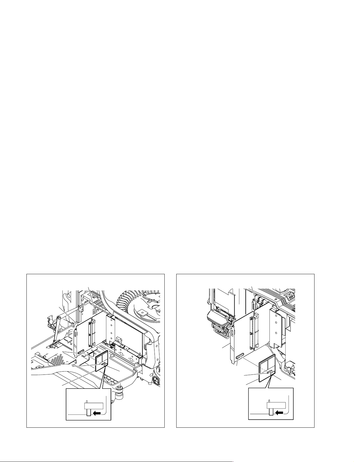
1-13-2. Upgrading the Boot Program
Tools
. Memory Stick
. ROM-28 board:
.
Extension board EX-738: (Sony Part No. : A-8327-351-A)
Preparation
1. Copy the upgrading program to the Memory Stick in
the following steps.
n
To get the upgrading program (program files
“hdc1000.rom” and “boot.rom”), contact your local
Sony Sales Office/Service Center.
(1) Make the following directory on the Memory
Stick.
\MSSONY\PRO\CAMERA\HDC1000
(2) Copy the program files “hdc1000.rom” and
“boot.rom” to the directory made by step (1).
(Sony Part No. : A-8326-017-A)
Procedures
1. Open the right side panel (HDC1000), or inside panel
(HDC1400/1500/1550/1580). (Refer to Section 1-4.)
2. Extend the AT-163 board using the EX-738 board.
3. Insert the Memory Stick in which the upgrading
program is already saved.
4. Connect the connector CN1 on the ROM-28 board to
the connector CN102 on the AT-163 board.
5. Set the switch S1 on the ROM-28 board to DOWN
LOAD side.
6. Turn on the power.
The upgrading status is displayed on the screen of the
view finder.
7. When the version upgrade is completed, the message
“Complete” will be displayed.
8. Turn off the power, and remove the ROM-28 board.
9. Put back the AT-163 board to the original position.
10. Turn on the power. The unit will start with the boot
program upgraded.
2. Save the upgrading Boot program in the ROMs H
(IC2) and L (IC3) on the ROM-28 board.
n
For details of saving the upgrading program, contact
your local Sony Sales Office/Service Center.
EX-738 board
AT-163 board
CN102
CN1
S1
ROM-28 board
EX-738 board
AT-163 board
CN102
CN1
S1
ROM-28 board
1-30
DOWN
LOAD
DOWN
LOAD
HDC1000 HDC1400/1500/1550/1580
HDC1000/V1(E)
Page 39

1-14. Writing and Rewriting the PLD
Internal Data
This unit uses the PLD (Programmable Logic Device) that
supports the e-Production (EPR) system to write and
rewrite the internal data.
If the part listed below needs to be replaced or to be
upgraded, contact your local Sony Sales Office/Service
Center.
n
The part number of PLD (or ROM for PLD) in which data
is not written yet, is shown in “Section 1. Spare Parts” of
Maintenance Manual Volume 2.
Therefore, if part replacement is required, write the data by
the following procedure.
In the case of the PLD type that runs on the program stored
in external ROM, data needs not to be written only by
replacing the part if the specific PLD only is defective.
e-Production system has the advantages shown
below.
. To write/rewrite the PLD internal data:
1. The standard fixture (cable) can be used.
2. The standard software (PLD Download Tool) can be
used.
. The PLD internal data is controlled in the Sony Database
Server under the name of Project file
(E_xxx_xxx_xx_xx).
. The printed circuit board is equipped with the standard
connector (EPR connector) to write the PLD internal
data. The indication “EPR” is shown on the printed
circuit board.
Corresponding PLD
PLD EPR connector Project file No.
(Ref No./board name) (Ref No./board name)
IC404/AT-163 CN401/AT-163
IC403/AT-163
IC201/DAP-33 CN2/DAP-33
IC202/DAP-33
IC408/SDI-84/84C CN202/SDI-84/84C*7E_000_001_91_xx
IC212/SDI-84/84C
(HDC1000/1400/1500)
IC9/TG-243/243B/243C
IC6/TG-243/243B/243C
IC501/TR-136 CN3/TR-136
IC504/TR-136
(HDC1550)
IC110/VDA-63 CN100/VDA-63
IC109/VDA-63
*1: IC403/AT-163 is the ROM for IC404/AT-163.
*2: IC202/DAP-33 is the ROM for IC201/DAP-33.
*3: IC212/SDI-84/84C is the ROM for IC408/SDI-84/84C.
*4: IC6/TG-243/243B/243C is the ROM for IC9/TG-243/243B/243C.
*5: IC504/TR-136 is the ROM for IC501/TR-136.
*6: IC109/VDA-63 is the ROM for IC110/VDA-63.
*7: The file name changes when upgrading.
*1
*2
*3
CN2/TG-243/243B/*7E_000_001_87_17
*4
243C
*5
*6
*7
E_000_001_88_xx
*7
E_000_001_89_xx
*7
E_000_003_01_xx
*7
E_000_001_90_xx
n
For checking the SDI-84 board, refer to Section 2-14.
Equipment required
. PLD download fixture
(Sony part number: J-7120-140-A)
The cable to connect PC to this unit.
. PC
A PC having parallel port.
A PC in which the PLD Download Tool software is
already installed.
For the applicable OS and the operating environment,
refer to “Download Tool Operating Instruction for
Device Programming”.
HDC1000/V1(E)
1-31
Page 40

Data writing procedure
Data writing procedure in the PLD (or ROM for PLD) is
outlined below.
For details of data writing procedure, refer to “Download
Tool Operating Instruction for Device Programming”,
which is available in the same site where the PLD Download Tool software is available.
1-15. Note on Replacement of Lithium
Battery
A lithium battery is mounted on the DAP-33 board to back
up Real Time Clock (RTC).
If a battery comes to the lifetime, then RTC stops.
Therefore the battery replacement is required.
1. Prepare the Project file.
n
Download the Project file from the Sony Database
Server.
2. Turn off the power of this unit. Connect the PC
parallel port to the EPR connector of the target board
using the PLD download fixture (cable).
3. Turn on the power of this unit.
Start the Download Tool software and read the Project
file.
4. Program the PLD (or ROM for PLD) with the Download Tool software.
5. Upon completion of programming, check that error
message is not displayed. Turn off the power of this
unit and back on.
DAP-33 board/CR2032 : Sony part No. (1-528-174-11)
c
In replacing, ensure that the battery is installed with “+”
and “_” poles connected to the correct terminals.
An improper connection may cause an explosion or
leakage of fluid.
1-32
HDC1000/V1(E)
Page 41

1-16. Recommended Replacing Parts
1-16-1. HDC1000
Following parts are recommended replacing parts. The
optical filter unit may become clouded with the lapse of
time. By such a cloudy optical filter unit, the characteristics of this camera could not fully exploited, therefore
replace it if necessary.
Besides, the parts made of rubber used for this camera may
become cracked and split with the lapse of time, therefore
also replace it if necessary.
4
1
421
1
No. Description Sony Part No.
1 KNOB (DIA 3) ASSY, VOLUME X-3167-563-X
2 KNOB, VOLUME 6 3-602-483-0X
3 CAP, CONNECTOR 3-605-338-0X
4 KNOB, VOLUME DIA.6 3-872-577-0X
5 SHIELD CUSHION (C) 3-615-750-6X
6 BAND, CLAMP 3-612-712-0X
7 PACKING, FAN 3-627-260-0X
8 FILTER UNIT, OPTICAL 1-758-483-11
5
5
6
5
1
7
7
5
8
3
HDC1000/V1(E)
1-33
Page 42
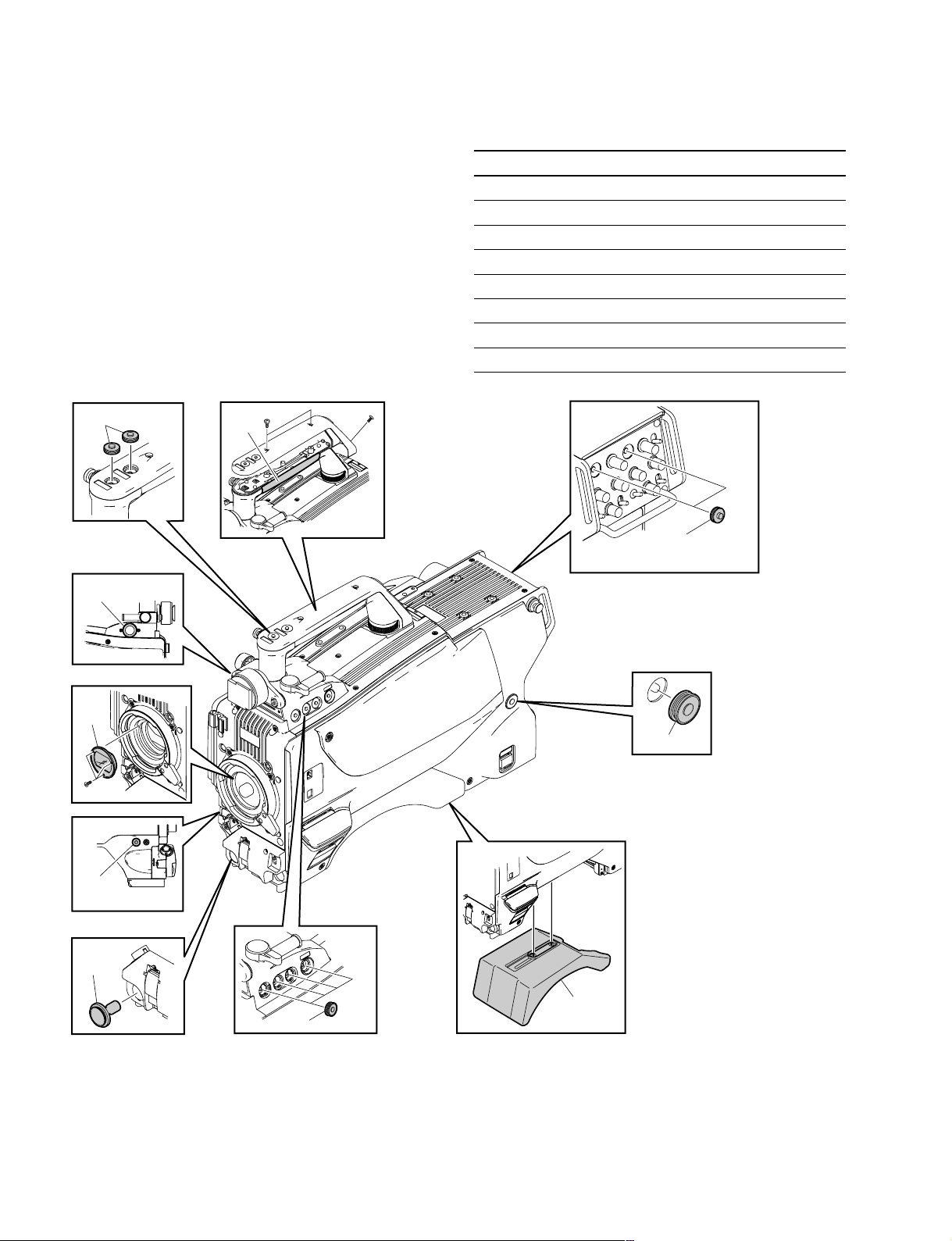
1-16-2. HDC1400/1500/1550/1580
Following parts are recommended replacing parts. The
optical filter unit may become clouded with the lapse of
time. By such a cloudy optical filter unit, the characteristics of this camera could not fully exploited, therefore
replace it if necessary.
Besides, the parts made of rubber used for this camera may
become cracked and split with the lapse of time, therefore
also replace it if necessary.
2
4
6
No. Description Sony Part No.
1 COVER, SWITCH 3-676-244-0X
2 COVER, SWITCH 3-676-244-2X
3 BUTTON, VTR START 3-679-668-0X
4 PACKING, VF 3-710-024-0X
5 CALL COVER 3-857-347-0X
6 SHEET, HANDLE 3-872-563-0X
7 PAD ASSY, SHOULDER A-8286-163-X
8 FILTER UNIT, OPTICAL 1-758-483-11
2
8
5
2
3
7
1
1-34
HDC1000/V1(E)
Page 43

1-16-3. Periodic Check/Replacement Parts
This table does not describe the guarantee period of part.
The replacement period of each part is changed according
to the environment and condition.
Refer to the “Section 2 Replacement of Main Parts” for the
replacement method of part.
. HDC1000
Description Sony Part No. Check/
Replacement Period
FAN, DC 1-787-497-11 Replace every two years
(60 SQUARE)
*: When used for eight hours a day.
. HDC1400/1500/1550/1580
Description Sony Part No. Check/
Replacement Period
FAN, DC 1-787-070-11 Replace every two years
(41 SQUARE)
*: When used for eight hours a day.
*
*
HDC1000/V1(E)
1-35
Page 44
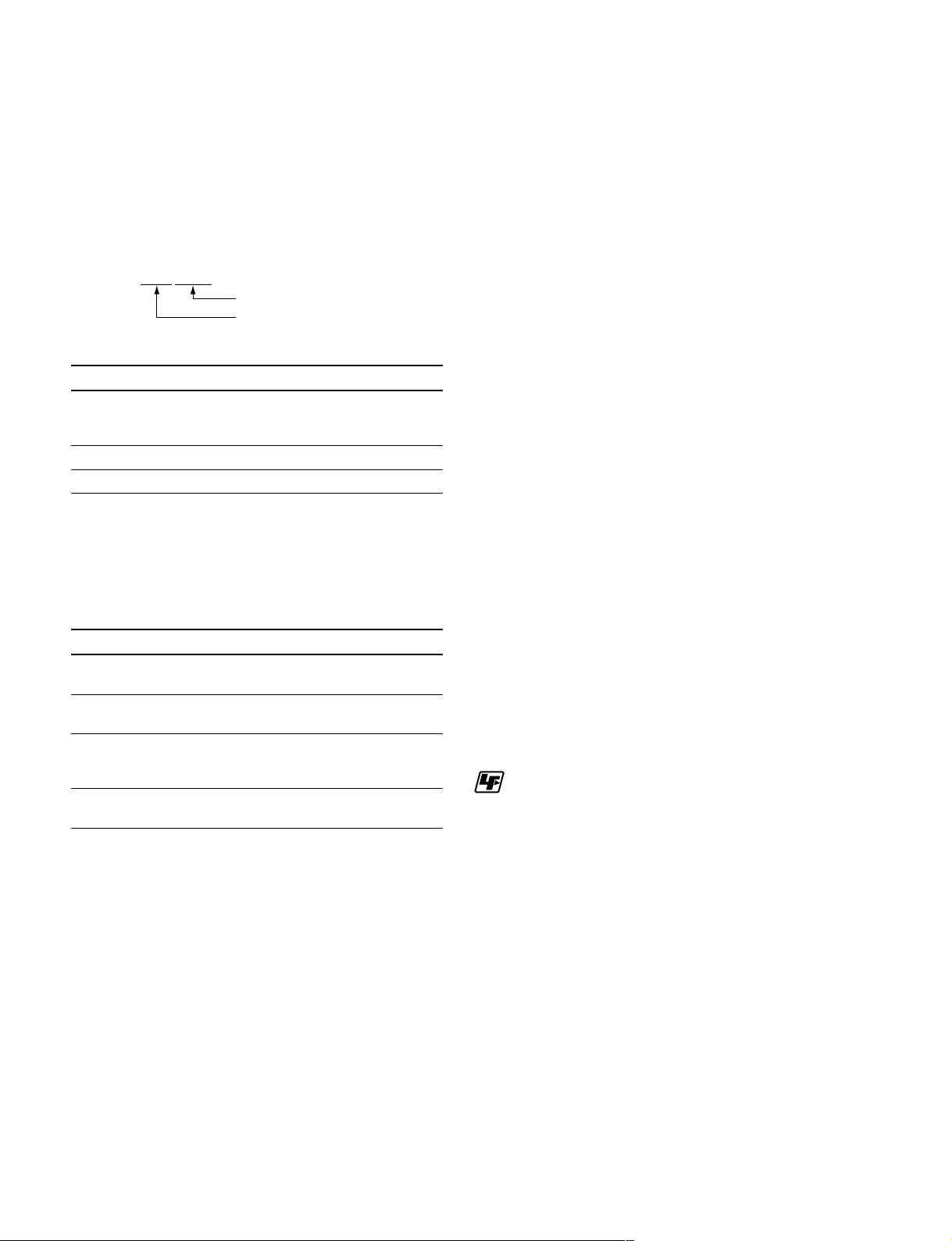
1-17. Description of CCD Block Number
1-19. Notes on Repair Parts
Every CCD unit has its own ID number called CCD block
number. It shows the CCD block type and serial number
for the CCD block.
The CCD block number label is put in the CCD unit.
Example : MDA xxxxx
Serial number for the CCD unit
CCD block type
Model CCD block type
HDC1000 MDC
HDC1500
HDC1550
HDC1400 MUA
HDC1580 MPB
For replacing the CCD unit, refer to Section 2-1.
1-18. Optional Fixtures
1. Safety Related Components Warning
w
Components marked ! are critical to safe operation.
Therefore, specified parts should be used in the case of
replacement.
2. Standardization of Parts
Some repair parts supplied by Sony differ from those
used for the unit. These are because of parts commonality and improvement.
Parts list has the present standardized repair parts.
3. Stock of Parts
Parts marked with “o” at SP (Supply Code) column of
the spare parts list may not be stocked. Therefore, the
delivery date will be delayed.
4. Harness
Harnesses with no part number are not registered as
spare parts.
Name Sony Part No. Remarks
EX-738 Board A-8327-351-A For extension of plug-in
boards
Extension assy, A-8344-327-A For extension of DPR-265
DPR-197 and SDI-84 boards.
Alignment sleeve J-6480-010-A For female connector
remover HC-001 LEMO® DCC.91.312.5LA
or equivalent
PLD download J-7120-140-A PLD data download
fixture cable
1-20. Unleaded Solder
Boards requiring use of unleaded solder are printed with a
lead free mark (LF) indicating the solder contains no lead.
(Caution: Some printed circuit boards may not come
printed with the lead free mark due to their particular size.)
: LEAD FREE MARK
m
. Be sure to use the unleaded solder for the printed circuit
board printed with the lead free mark.
. The unleaded solder melts at a temperature about 40 dC
higher than the ordinary solder, therefore, it is recommended to use the soldering iron having a temperature
regulator.
. The ordinary soldering iron can be used but the iron tip
has to be applied to the solder joint for a slightly longer
time. The printed pattern (copper foil) may peel away if
the heated tip is applied for too long, so be careful.
1-36
HDC1000/V1(E)
Page 45
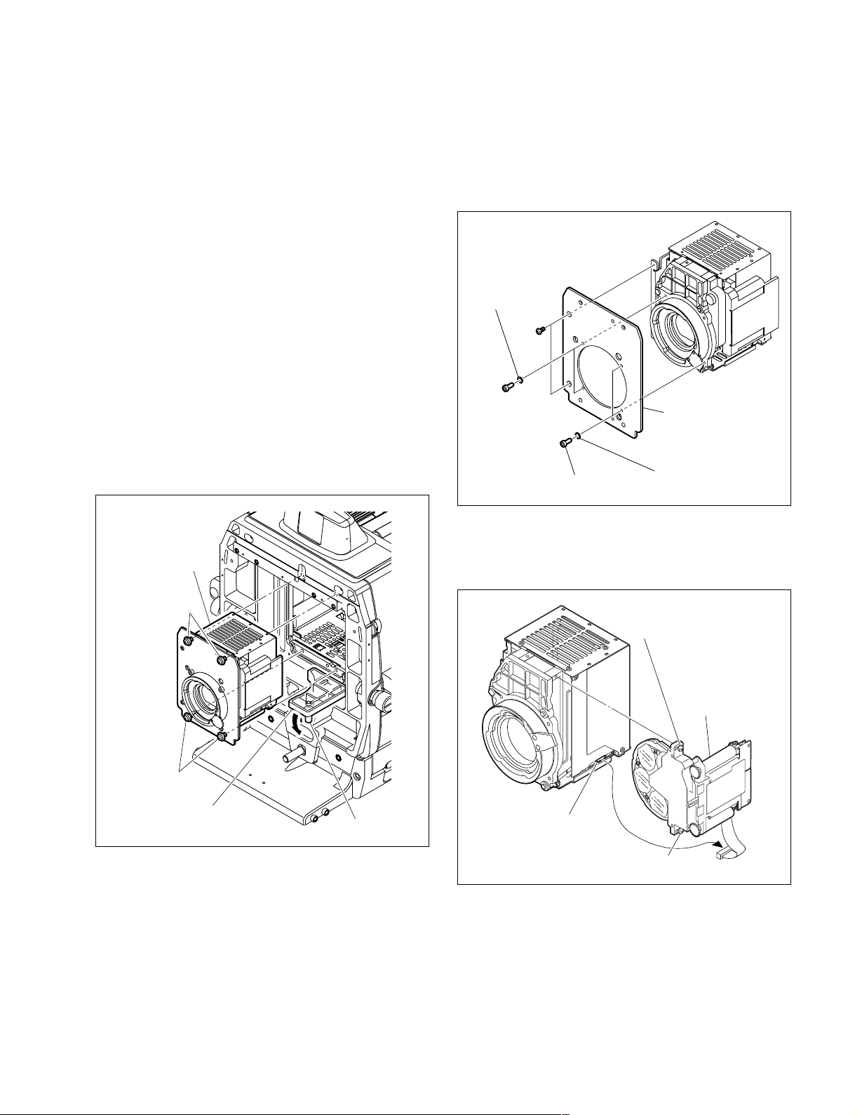
Section 2
Replacement of Main Parts
2-1. Replacing the CCD Unit
n
Never remove or install the CCD unit with the power
turned on. Because touching internal harness to the cabinet
or other printed circuit boards during replacement causes
short circuits or electric hazards.
Prior to replacement, be sure to disconnect the optical/
electrical cable or the cable connected to the DC IN
connector in addition to turning off power switch.
2-1-1. HDC1000
1. Loosen the screw of the mount lever fixing lid, and
open the mount lever fixing lid in the arrow direction.
2. Loosen the four screws of front assembly, and remove
the front assembly.
Front assembly
PWH4 x 10
(with stopper)
3. Remove the two screws and four hexagon-socket bolts,
and remove the four spring washers, and front panel
assembly.
Spring washers
B2.6 x 6
Hexagon-socket
bolts (3 x 8)
Hexagon-socket bolts
(3 x 8)
Front panel assembly
Spring washers
4. Disconnect the harness from the connector of CCD
unit, loosen the two fixing screws of the filter disk
unit, and remove the filter disk unit.
Fixing screw of the
filter disk unit (with stopper)
PWH4 x 10
(with stopper)
HDC1000/V1(E)
Mount lever fixing lid
Screw
Filter disk unit
Connector
Fixing screw of the
filter disk unit (with stopper)
2-1
Page 46
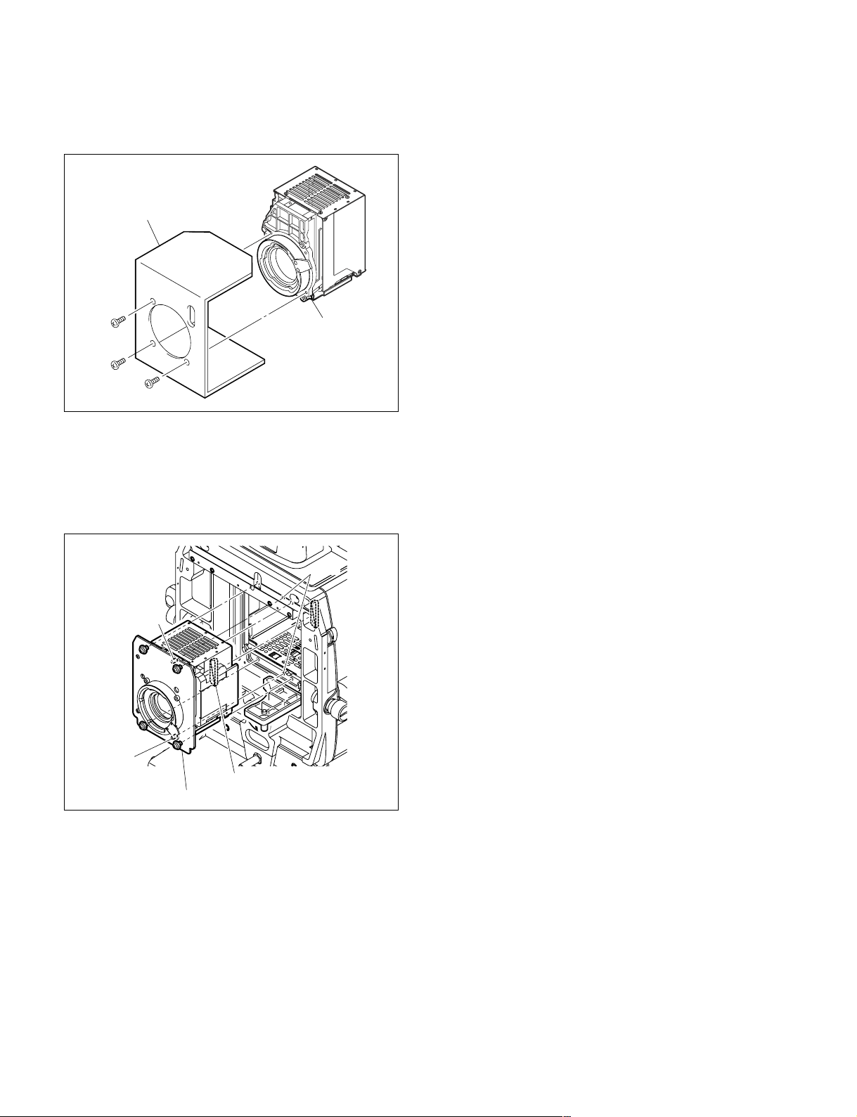
5. Remove the three screws, and remove the transportation holder from the CCD unit for repair (option).
Transportation holder
P3 x 6
P3 x 6
P3 x 6
CCD unit
6. Install the CCD unit by reversing the steps above.
n
When installing the CCD unit, adjust the boss of the
front assembly to the hole on the chassis and connect
the connector firmly.
Holes
Boss
2-2
Boss
Connector
Front assembly
HDC1000/V1(E)
Page 47
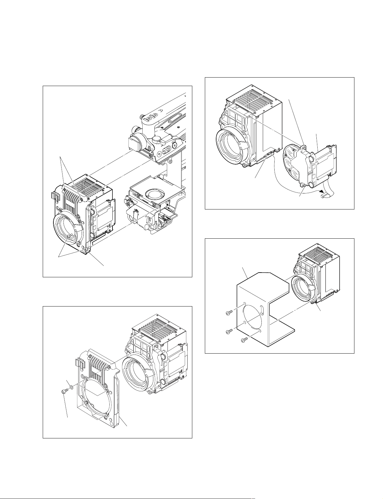
2-1-2. HDC1400/1500/1550/1580
1. Loosen the four screws, and remove the front assembly.
B3 x 10
(with stopper)
3. Disconnect the harness from the connector of CCD
unit, loosen the two fixing screws of the filter disk
unit, and remove the filter disk unit.
Fixing screw of the
filter disk unit (with stopper)
Filter disk unit
Connector
Fixing screw of the
filter disk unit (with stopper)
4. Remove the three screws, and remove the transportation holder from the CCD unit for repair (option).
B3 x 10
(with stopper)
Front assembly
2. Remove the four hexagon-socket bolts and four spring
washers, and remove the front panel assembly.
Spring
washers
Hexagon-soket bolts
(3 x 8)
Front panel assembly
Transportation holder
P3 x 6
P3 x 6
P3 x 6
CCD unit
5. Install the CCD by reversing the steps above.
HDC1000/V1(E)
2-3
Page 48
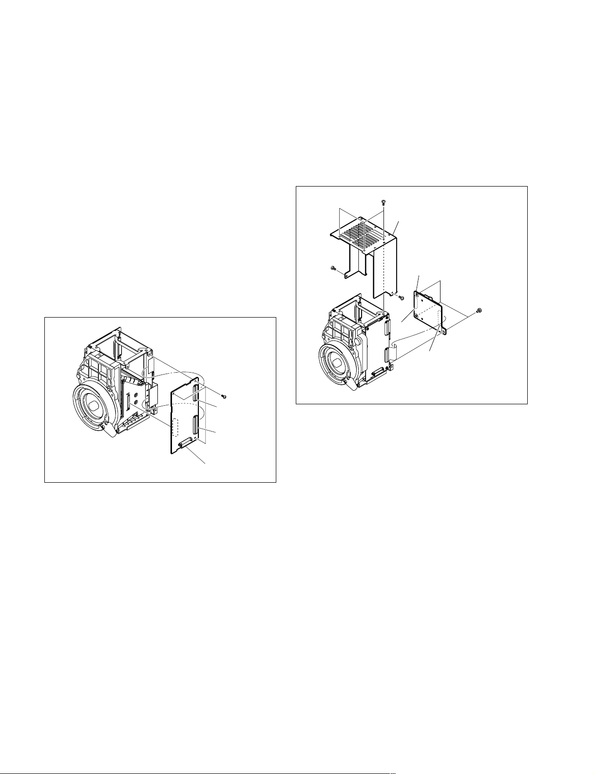
4
2-2. Replacement of CCD Unit Boards
2-2-2. CN-2579 Board
When replacing the boards in the CCD unit, remove the
CCD unit from the main unit in advance.
For removing the CCD unit, refer to Section 2-1.
n
Be careful not to bend the flexible card wire. This shortens
the wire life. (Refer to Section 1-10.)
2-2-1. DR-528 Board
1. Remove the five screws to detach the OHB cover.
(Refer to Section 2-2-2.)
2. Disconnect the flexible card wires from the connectors
(CN1, CN2) on the DR-528 board.
3. Remove the three screws to remove the DR-528 board.
Install the board by reversing the steps above.
1. Remove the five screws to detach the OHB cover.
2. Disconnect the flexible card wires from the connectors
(CN1, CN2) on the CN-2579 board.
3. Remove the three special screws to remove the CN2579 board.
Install the board by reversing the steps above.
B2 x 4
OHB cover
B2 x 4
B2 x 4
CN1
CN-2579 board
Special
screws (M2)
CN2
CN1
CN2
DR-528 board
B2 x
2-4
HDC1000/V1(E)
Page 49
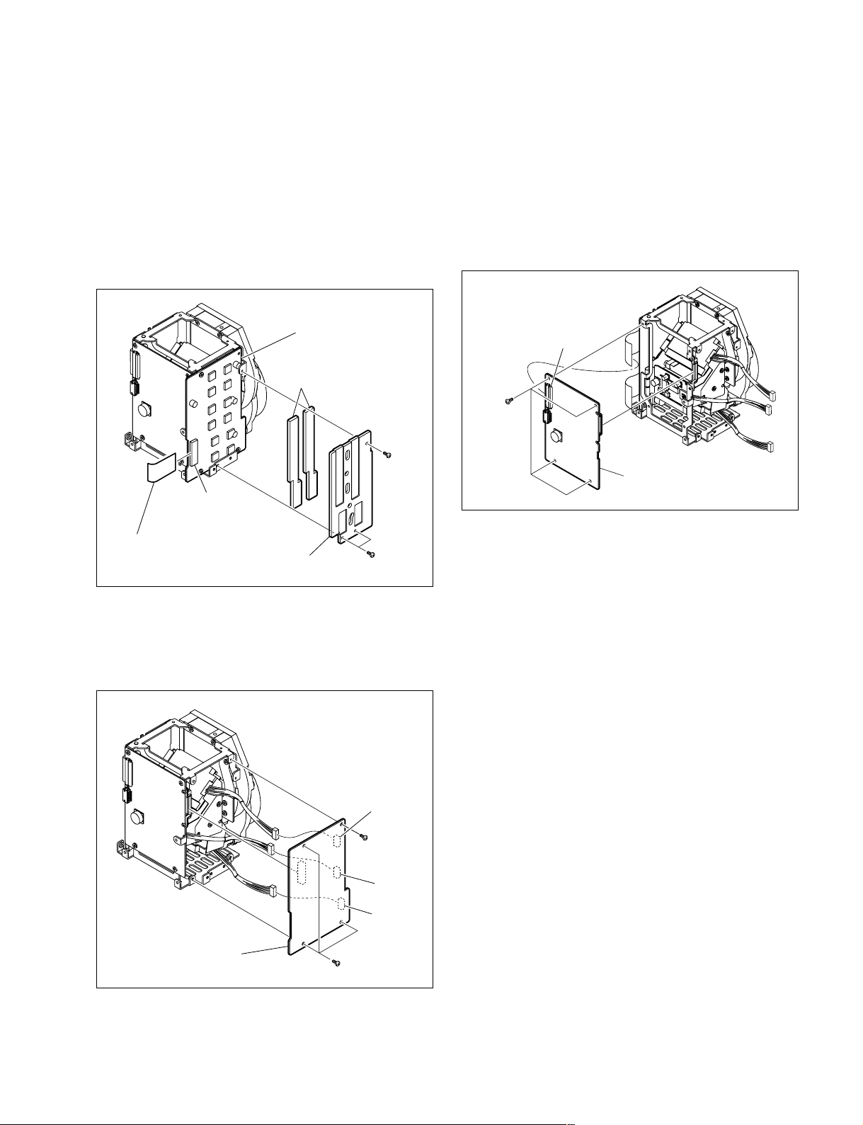
4
2-2-3. PA-317 Board
2-2-4. TG-243 Board
1. Remove the five screws to detach the OHB cover.
(Refer to Section 2-2-2.)
2. Disconnect the flexible card wire from the connector
(CN402) on the PA-317 board.
3. Remove the three screws to detach the heat conduction
plate.
4. Peel the two heat transfer sheets off the PA-317 board.
PA-317 board
Heat transfer sheets
B2 x
CN402
Flexible card wire
Heat conduction plate
B2 x 4
1. Remove the CN-2579 board. (Refer to Section 2-2-2.)
2. Remove the PA-317 board. (Refer to Section 2-2-3.)
3. Disconnect the flexible card wire from the connector
(CN1) on the TG-243 board.
4. Remove the four screws to remove the TG-243 board.
Install the board by reversing the steps above.
CN1
B2 x 4
TG-243 board
5. Remove the four screws to remove the PA-317 board.
6. Disconnect the harness from the connectors (CN101,
CN201, and CN301) on the PA-317 board.
Install the board by reversing the steps above.
CN301
B2 x 4
CN201
CN101
PA-317 board
B2 x 4
HDC1000/V1(E)
2-5
Page 50
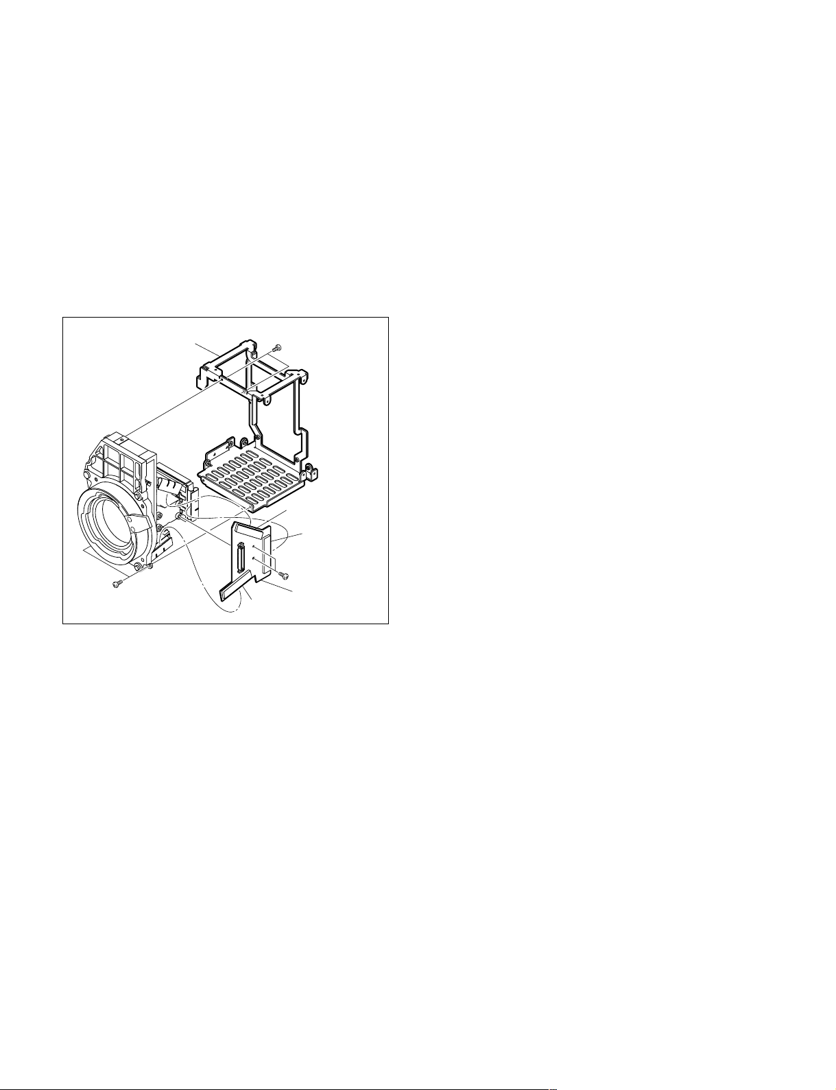
2-2-5. CN-2578 Board
1. Remove the CN-2579 board. (Refer to Section 2-2-2.)
2. Remove the DR-528 board. (Refer to Section 2-2-1.)
3. Remove the PA-317 board. (Refer to Section 2-2-3.)
4. Remove the TG-243 board. (Refer to Section 2-2-4.)
5. Remove the four screws to detach the OHB holder.
6. Disconnect the flexible card boards from the connectors (CN2, CN3, and CN4) on the CN-2578 board.
7. Remove the two screws to remove the CN-2578 board.
Install the board by reversing the steps above.
B2 x 4
OHB holder
B2 x 4
CN3
CN4
B2 x 4
CN-2578 board
CN2
2-6
HDC1000/V1(E)
Page 51
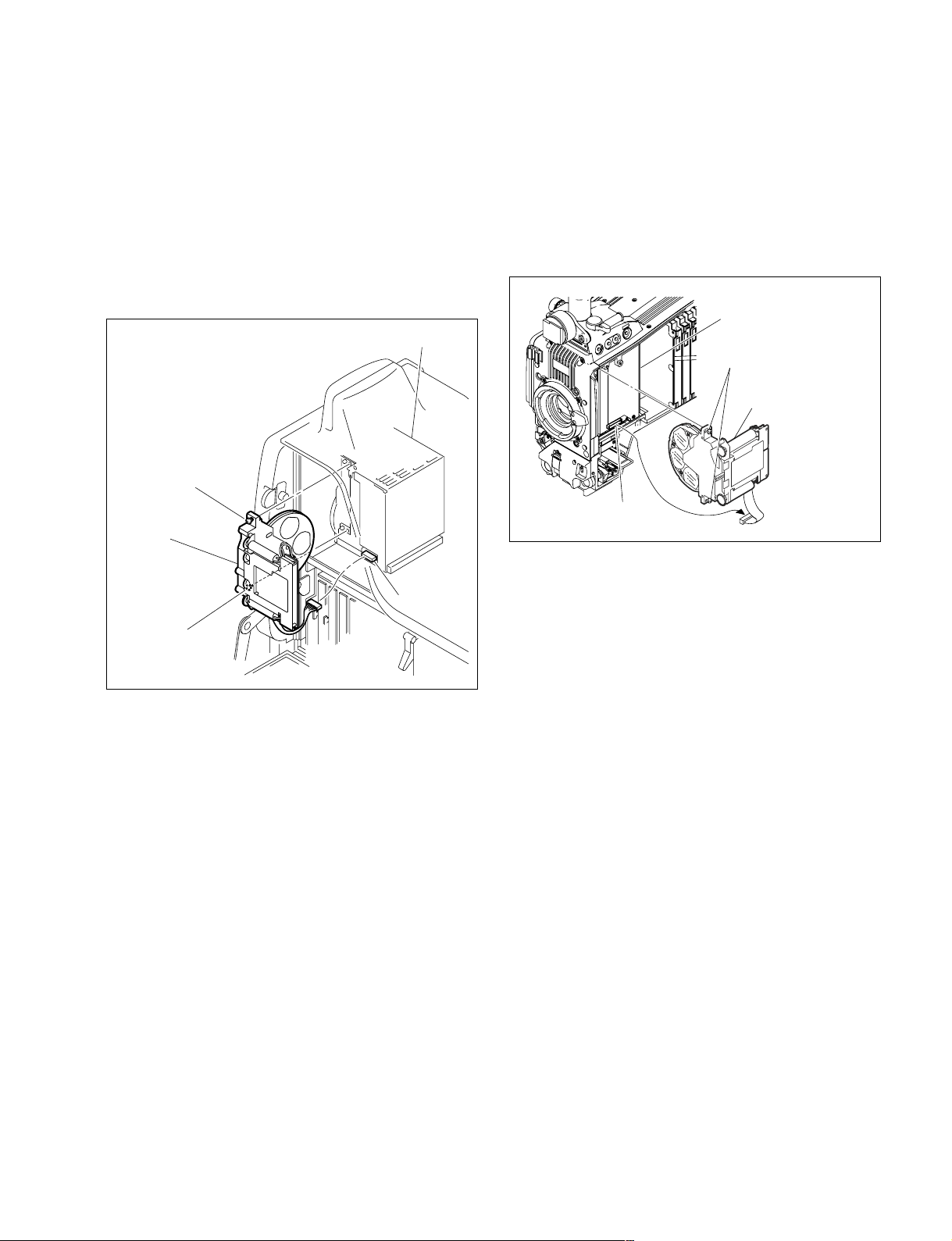
2-3. Replacing the Filter Disk Unit
Connector
CCD unit
Filter disk unit
Fixing screws of the
filter disk unit (with stopper)
2-3-2. HDC1400/1500/1550/1580
2-3-1. HDC1000
1. Open the right side panel. (Refer to Section 1-4.)
2. Disconnect the harness of the filter disk unit from the
connector of the CCD unit.
3. Loosen the two fixing screws of the filter disk unit,
and remove the filter disk unit.
CCD unit
Fixing screw of the
filter disk unit
(with stopper)
Filter disk unit
Connector
Fixing screw of the
filter disk unit
(with stopper)
1. Remove the inside panel. (Refer to Section 1-4.)
2. Disconnect the harness of the filter disk unit from the
connector of the CCD unit.
3. Loosen the two fixing screws of the filter disk unit,
and remove the filter disk unit.
4. Install the filter disk unit by reversing the steps above.
n
In installation, do not touch the surface of filters.
4. Install the filter disk unit by reversing the steps above.
n
In installation, do not touch the surfaces of filters.
HDC1000/V1(E)
2-7
Page 52

2-4. Replacing the Fan (HDC1000)
5. Detach the fan packing, and remove the DC fan.
c
If the fan is out of order, the inside temperature of the unit
will rise. Touching the inside in this state may cause a
burn. When replacing the fan, allow a few minutes after
powering off until the inside cools off.
2-4-1. DC Fan (TOP)
When replacing, be sure to use the specified part.
DC Fan (TOP: 60 square): ! 1-787-497-11
1. Open the left side panel. (Refer to Section 1-4.)
2. Loosen the two screws with stopper, and disconnect
the harness from the connector (CN1) on the CN-2602
board.
3. Pull the notch on the fan assembly from the protrusion
on the fan bracket, and remove the fan assembly.
4. Cut the two binding bands, and remove the ferrite
bead.
Protrusion
Holes
Fan bracket
Protrusions
Fan packing
Label side
Protrusions
DC fan
6. Install the DC fan by reversing the steps above.
m
. Be careful of the orientation of the label side and the
harness when installing the DC fan.
. To install the fan assembly, fit the notch on the fan
assembly to the protrusion on the fan bracket, and
the protrusions on the fan packing to the holes on the
fan bracket.
. Attach the ferrite bead as following figure, and fix it
by the two binding bands.
CN-2602 board
2-8
CN1
Notch
Protrusions
DC fan
Binding bands
Fan assembly
Screws with stopper
Ferrite bead
150 mm
Binding band
Ferrite bead
Binding band
HDC1000/V1(E)
Page 53
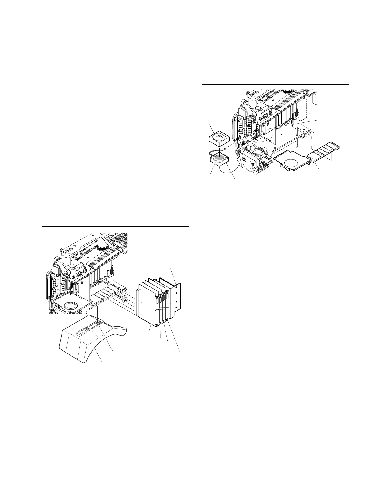
2-5. Replacing the Fan (HDC1400/1500/
1550/1580)
n
If any fan fails, the inside temperature of the unit will rise.
Touching the inside in this state may cause a burn. Power
off the unit and leave the unit until the inside cools down
before replacing the fan.
2-5-1. DC Fan (Front)
When replacing, be sure to use the specified part.
DC Fan (Front: 41 square): ! 1-787-070-11
5. Remove the three screws to detach the lower rail.
6. Disconnect the fan harness from the connector (CN4)
on the MB-1059 board.
7. Remove the cushion (FAN) from the DC fan.
Cushion
(FAN)
MB-1059 board
CN4
BTP2.6 x 6
1. Remove the inside panel. (Refer to Section 1-4.)
2. Remove the front assembly. (Refer to Section 2-1.)
3. Loosen the two screws with stopper, and remove the
shoulder pad assembly.
4. Draw all the plug-in boards and the DC/DC converter
unit along the board rail grooves and remove them.
DC-DC converter unit
VDA-63 board
DAP-33 board
AU-298 board
Screws with stopper
Shoulder pad assembly
AT-163 board
label side
DC fan
Lower rail
8. Install the front DC fan by reversing the steps above.
n
Be careful of the orientation of the label side and the
harness when installing the DC fan.
HDC1000/V1(E)
2-9
Page 54
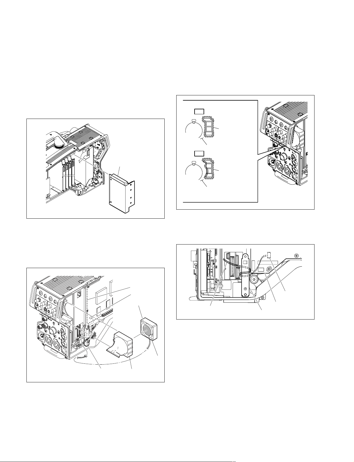
2-5-2. DC Fan (Rear)
When replacing, be sure to use the specified part.
DC Fan (Rear: 41 square): ! 1-787-070-11
1. Remove the inside panel and outside panel.
(Refer to Section 1-4.)
2. Draw the DC/DC converter unit along the board rail
grooves and remove it.
DC-DC converter
6. Install the rear DC fan by reversing the steps above.
m
. Be careful of the orientation of the label side and the
harness when installing the DC fan.
. Attach the duct (fan) to the INCOM panel correctly
so as to not block the ventilative hole.
OK
Duct (fan)
INCOM panel
NG
Duct (fan)
INCOM panel
3. Disconnect the fan harness from the connector (CN18)
on the MB-1059 board.
4. Remove the fan harness from the DPR rear bracket,
and remove the duct (fan).
5. Detach the DC fan from the duct (fan).
MB-1059 board
CN18
Label side
DC fan
DPR rear bracket
Duct (fan)
. Arrange the fan harness around the DPR rear bracket
as shown below, and then connect it to the connector
(CN18) on the MB-1059 board.
CN18
Fan harness
DPR rear bracket
MB-1059 board
2-10
HDC1000/V1(E)
Page 55
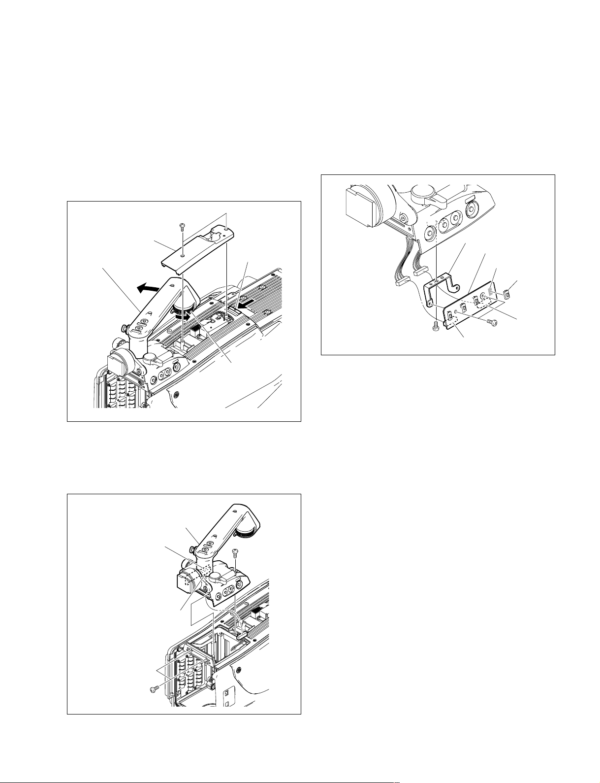
2-6. Replacing the VF DISP Switches
(HDC1400/1500/1550/1580)
(SW-1237 Board)
1. Remove the front assembly. (Refer to Section 2-1.)
2. Loosen the handle lock knob, and turn the handle
while pressing the lever.
3. Remove the two screws, and remove the top cover (02)
while pressing the lever.
Screws (M2)
Top cover (02)
Lever
Handle
6. Disconnect the harnesses from the connectors (CN1,
CN2) on the SW-1237 board.
7. Remove the screw, and remove the SW-1237 board.
8. Remove the two screws to detach the filter bracket
from the SW-1237 board.
9. Unsolder the switch to be replaced from the SW-1237
board.
Filter bracket
SW-1237 board
Unsolder
Switch
Handle lock knob
4. Remove the three screws and pull out the handle
holder assembly.
5. Disconnect the harness from the connector (CN3) on
the CN-2614 board.
Handle holder assembly
CN-2614 board
B3 x 8
CN2
B2 x 4
B2 x 4
CN1
10. Install a new switch by reversing the steps above.
HDC1000/V1(E)
CN3
B3 x 8
2-11
Page 56
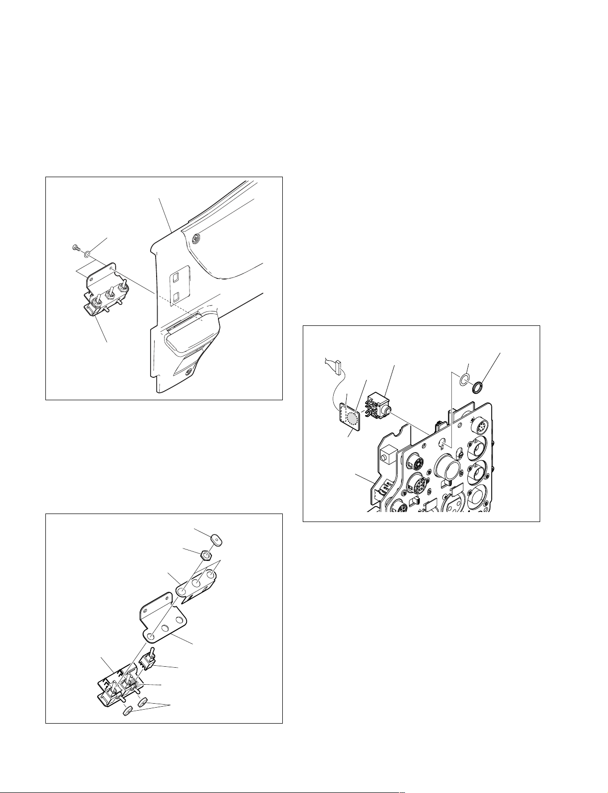
2-7. Replacing the Side Switch Panel
Assembly (HDC1400/1500/1550/
1580) (SW-1240 Board)
1. Remove the inside panel. (Refer to Section 1-4.)
2. Remove the two screws, and remove the side switch
panel assembly.
2-8. Replacing the Connectors
(HDC1400/1500/1550/1580)
n
Be careful not to bend the flexible card wire. This shortens
the wire life. (Refer to Section 1-10.)
Inside panel
B2.6 x 5
Side switch panel
assembly
Washers
3. Remove the five toggle switch cushions from the side
switch panel assembly.
4. Remove the three nuts to detach the inside switch
bracket and the toggle switch plate from the SW-1240
board.
5. Unsolder the switch to be replaced from the SW-1240
board.
2-8-1. EARPHONE Jack (CN-2640 Board)
1. Remove the MIC panel assembly.
(Refer to Section 2-8-2.)
2. Disconnect the harness from the connector (CN1) on
the CN-2640 board.
3. Remove the fixing nut of the EARPHONE jack to
detach the washer and the CN-2640 board.
4. Unsolder the EARPHONE jack from the CN-2640
board.
Fixing nut of the
EARPHONE jack
EARPHONE jack
Unsolder
CN1
CN-2640 board
MIC panel
assembly
Washer
Toggle SW cushions
Nuts
Inside SW bracket
Toggle SW plate
SW-1240 board
Switch
Unsolder
Toggle SW cushions
6. Install a new switch by reversing the steps above.
2-12
5. Install a new EARPHONE jack by reversing the steps
above.
HDC1000/V1(E)
Page 57
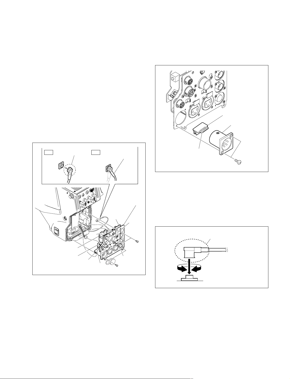
2-8-2. DC IN Connector (CN-2623 Board)
1. Remove the four screws, and pull out the MIC panel
assembly.
2. Disconnect the flexible card wires from the connector
(CN1) on the CN-2619 board and from the connector
(CN1) on the CN-2621 board.
3. Disconnect the harnesses from the connector (CN2) on
the CN-2619 board and from the connector (CN2) on
the CN-2623 board.
4. Disconnect the coaxial cable from the SDI 2 connector
(HDC1500) or SDI connector (HDC1550), and
remove the MIC panel assembly.
n
Be sure to hold the plug when disconnecting the
coaxial cable. Do not pull the cable.
5. Remove the two screws, and remove the CN-2623
board.
6. Unsolder the DC IN connector from the CN-2623
board.
CN-2623 board
DC IN Connector
Hold the plug to
OK NG
remove.
CN1
CN-2621 board
CN2
CN2
CN-2623 board
Do not attempt to
remove by pulling
the cable.
MIC panel assembly
CN-2619
board
Screws
(M2)
SDI 2/SDI
connector
Screws (M2)
CN1
Unsolder
Screws
(M2)
7. Install a new DC IN connector by reversing the steps
above.
n
Hold the plug of the coaxial cable, and connect it
perpendicularly to the connector.
Push the plug into the connector while turning it
clockwise and counterclockwise several times.
Hold the plug to connect
Connecting connector
HDC1000/V1(E)
2-13
Page 58
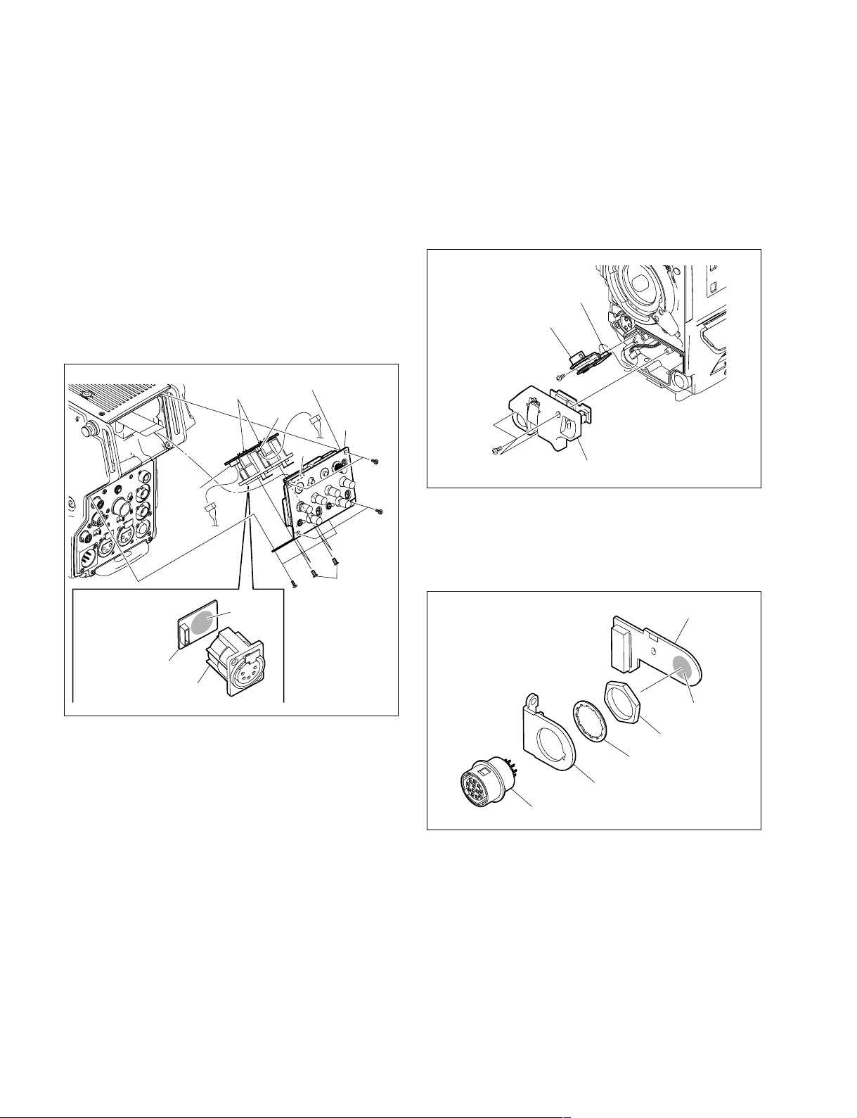
2-8-3. INTERCOM 1/2 Connector
(CN-2618 Board)
1. Remove the six screws and pull out the INTERCOM
panel assembly.
2. Disconnect the flexible card wire from the connector
(CN1) on the SW-1273 board.
3. Remove the two screws, and remove the CN-2618
board.
4. Disconnect the harness from the connector (CN1) on
the CN-2618 board.
5. Unsolder the INTERCOM 1 or INTERCOM 2 connector from the CN-2618 board.
CN-2618 board
CN1
SW-1273 board
INTERCOM
CN1
panel
assembly
CN1
Screws
(M2)
2-8-4. LENS Connector (CN-2616 Board)
1. Remove the three screws, and pull out the front switch
cover assembly.
2. Remove the screw, and pull out the CN-2616 board.
3. Disconnect the harness from the connector (CN2) on
the CN-2616 board.
CN2
CN-2616 board
P2 x 4
Screws (M2)
Front switch cover assembly
Screws
(M2)
P2.6 x 5
CN-2618 board
INTERCOM 1/2 connector
Unsolder
Screws
(M2)
6. Install a new INTERCOM 1 or INTERCOM 2 connector by reversing the steps above.
4. Unsolder the LENS connector from the CN-2616
board.
5. Remove the nut to detach the washer and lens bracket
from the LENS connector.
CN-2616 board
Unsolder
Nut
Washer
Lens bracket
LENS connector
6. Install a new LENS connector by reversing the steps
above.
2-14
HDC1000/V1(E)
Page 59
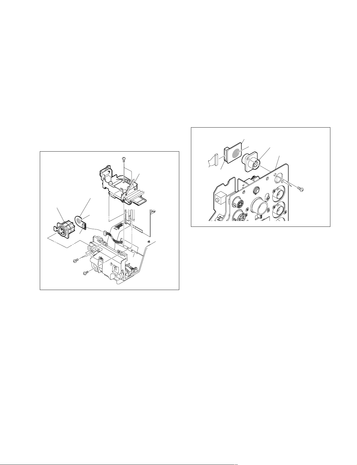
2-8-5. MIC 1 IN Connector (CN-2615 Board)
2-8-6. REMOTE Connector (CN-2622 Board)
1. Remove the inside panel and outside panel.
(Refer to Section 1-4.)
2. Remove the DC fan (front). (Refer to Section 2-5-1.)
3. Remove the four screws, and lift the sub frame
assembly.
4. Remove the two screws, and remove the CN-2615
board.
5. Disconnect the harness from the connector (CN3) on
the CN-2615 board.
6. Unsolder the MIC 1 IN connector from the CN-2615
board.
B2.6 x 5
Sub frame assembly
CN-2615 board
MIC 1 IN connector
Unsolder
1. Remove the MIC panel assembly.
(Refer to Section 2-8-2.)
2. Remove the two screws, and remove the CN-2622
board.
3. Disconnect the harness from the connector (CN1) on
the CN-2622 board.
4. Unsolder the REMOTE connector from the CN-2622
board.
CN-2622 board
Unsolder
CN1
REMOTE connector
MIC panel assembly
P2.6 x 5
CN3
P2.6 x 5
B2.6 x 5
7. Install a new MIC 1 IN connector by reversing the
steps above.
5. Install a new REMOTE connector by reversing the
steps above.
HDC1000/V1(E)
2-15
Page 60
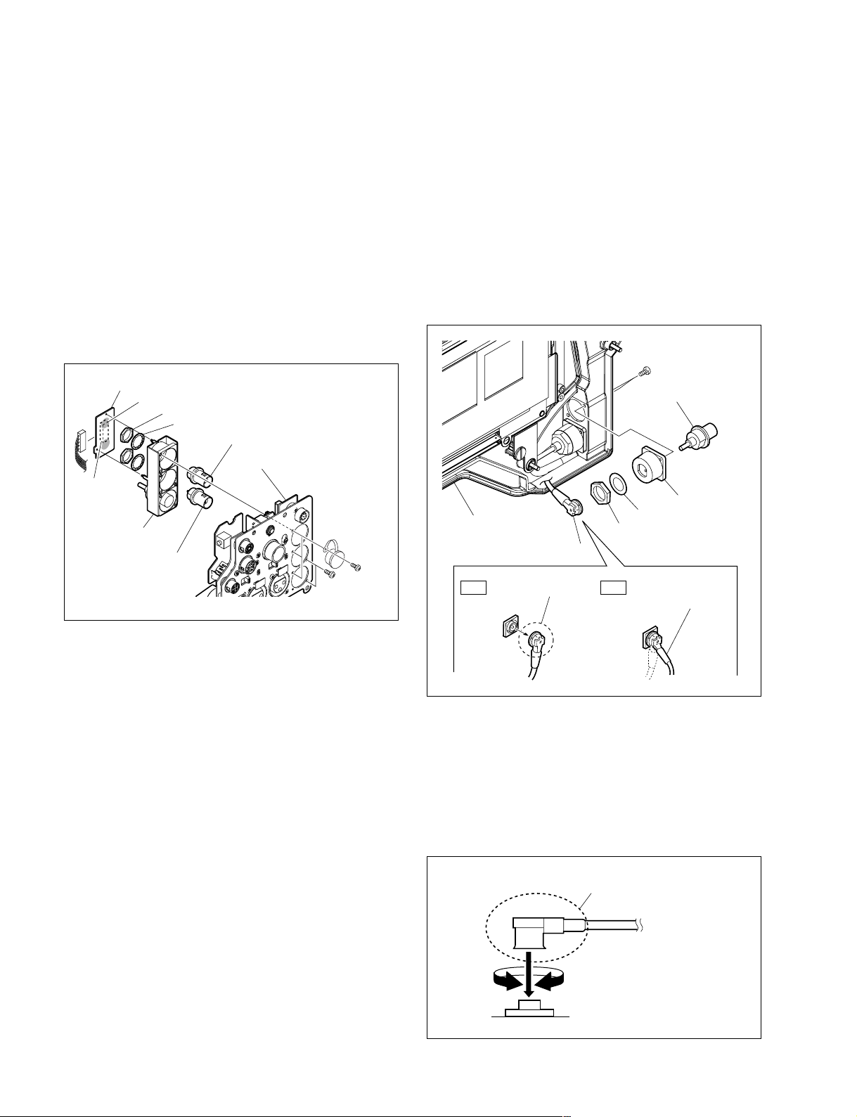
2-8-7. RET IN, TEST OUT Connector
(CN-2620 Board)
1. Remove the MIC panel assembly.
(Refer to Section 2-8-2.)
2. Remove the five screws, and remove the BNC assembly.
3. Disconnect the harness from the connector (CN3) on
the CN-2620 board.
4. Unsolder the RET IN, TEST OUT connector from the
CN-2620 board.
5. Remove the nut to detach the RET IN, TEST OUT
connector.
2-8-8. SDI 1 Connector (HDC1500)
1. Remove the outside panel. (Refer to Section 1-4.)
2. Remove the two screws to detach the BNC bracket.
3. Disconnect the coaxial cable from the SDI 1 connector.
n
Be sure to hold the plug when disconnecting the
coaxial cable. Do not pull the cable.
4. Remove the nut to detach the SDI 1 connector.
CN-2620 board
Unsolder
Nut
Washer
RET IN connector
MIC panel assembly
CN3
BNC assembly
TEST OUT connector
Screws
(M2)
6. Install a new RET IN, TEST OUT connector by
reversing the steps above.
Screws
(M2)
Screws (M2)
SDI 1 connector
BNC bracket
Out side panel
Coaxial cable
Hold the plug to
OK NG
remove.
Washer
Nut
Do not attempt to
remove by pulling
the cable.
5. Install a new SDI 1 connector by reversing the steps
above.
n
Hold the plug of the coaxial cable, and connect it
perpendicularly to the connector.
Push the plug into the connector while turning it
clockwise and counterclockwise several times.
2-16
Hold the plug to connect
Connecting connector
HDC1000/V1(E)
Page 61
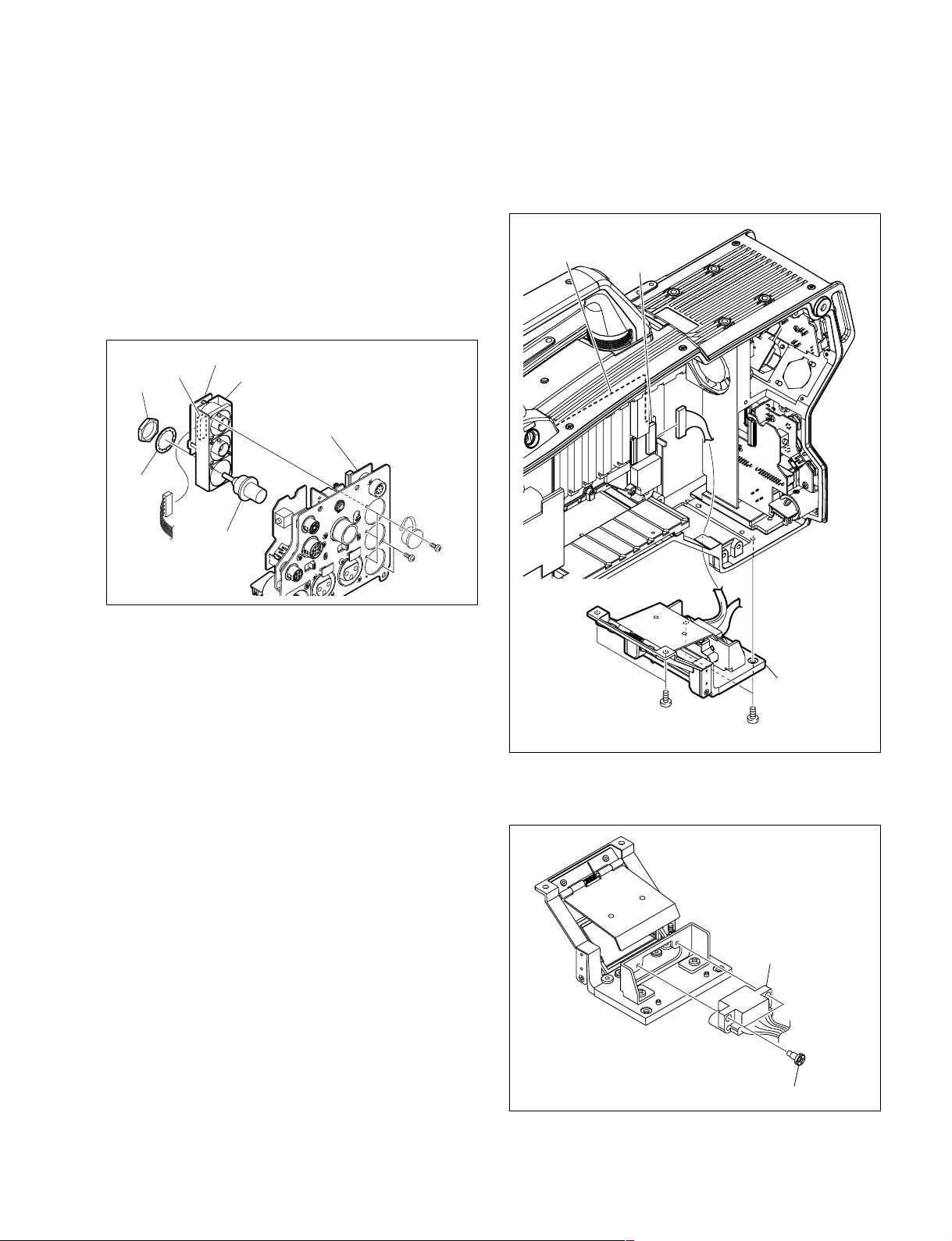
B3 x 8
B3 x 8
CN17
MB-1059 board
Hot shoe assembly
2-8-9. SDI 2 Connector (HDC1500)
SDI Connector (HDC1400/1550)
1. Remove the MIC panel assembly.
(Refer to Section 2-8-2.)
2. Remove the five screws, and remove the BNC assembly.
3. Disconnect the harness from the connector (CN3) on
the CN-2620 board.
4. Remove the nut to detach the SDI 2/SDI connector.
CN-2620 board
Nut
Washers
CN3
BNC assembly
SDI 2/SDI
connector
MIC panel assembly
Screws
(M2)
Screws
(M2)
3. Disconnect the harness from the connector (CN17) on
the MB-1059 board.
4. Remove the four screws, and remove the hot shoe
assembly.
5. Install a new SDI 2/SDI connector by reversing the
steps above.
2-8-10. BUILD UP Connector
(Hot Shoe Assembly)
1. Remove the inside panel and outside panel.
(Refer to Section 1-4.)
2. Remove the switching regulator.
(Refer to Section 2-11-2.)
5. Remove the two fixing screws of the connector and
remove the BUILD UP connector.
BUILD UP connector
HDC1000/V1(E)
Screw of the connector
6. Install a new BUILD UP connector by reversing the
steps above.
2-17
Page 62
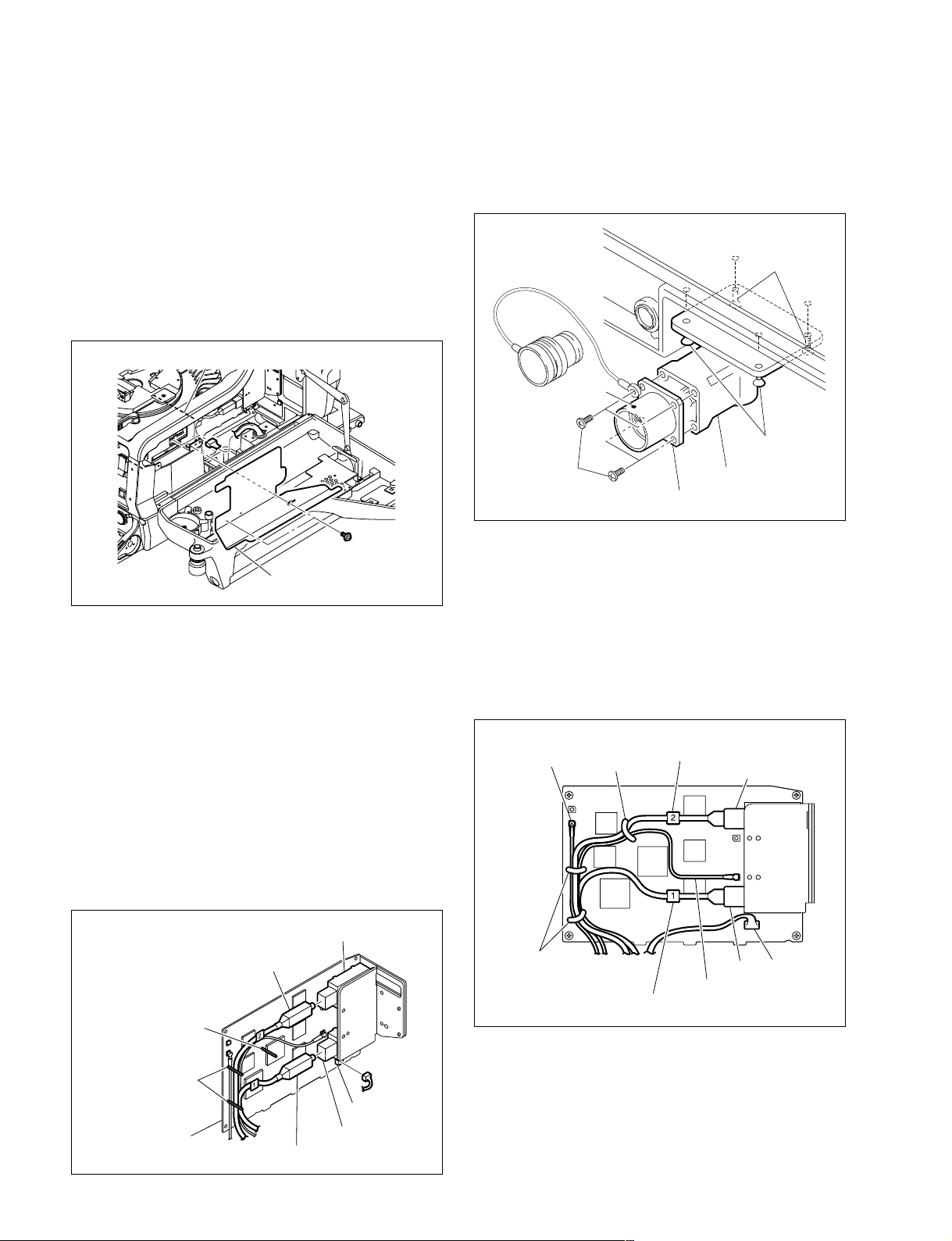
2-9. Replacing the Encapsulated Cable
Assembly/TRIAX Assembly
2-9-1.
1. Open the left side panel. (Refer to Section 1-4.)
2. Remove the two screws, and remove the harness
3. Disconnect the harness of the encapsulated cable
HDC1000 (Encapsulated Cable Assembly)
guard.
assembly from the power assembly.
Power assembly
7. Remove the four screws, and remove the connector
box.
8. Remove the four screws, and pull out the encapsulated
cable assembly.
K3 x 8
Mark
K3 x 8
B3 x 8
Encapsulated cable assembly
Connector box
PWH3 x 5
Harness guard
4. Release the harness and cables from the three harness
clamps.
5. Disconnect the harness from the connector (CN102)
on the SDI-84 board.
6. Disconnect the optical fiber cables from the E/O
converter module CP201 and O/E converter module
CP401 on the SDI-84 board.
m
. If optical fiber cable is bent or pulled strongly, it
may be disconnected. Handle optical fiber cables
carefully.
. Do not touch the tip of optical fiber cable connector.
This may result in deterioration of signals.
CP401
Optical fiber cable
Harness clamp
9. Install the encapsulated cable assembly by reversing
the steps above.
m
. Check cable numbers when connecting optical fiber
cables, and insert the cable connector as far as it will
go.
. Arrange the harness and cables as shown below, and
clamp them with the three harness clamps.
Coaxial cable
(green)
Harness clamps
Harness clamp
Optical fiber cable (No.1)
Optical fiber cable (No.2)
CP401
CN102
CP201
Coaxial cable (brown)
Harness clamps
2-18
SDI-84 board
CP201
Optical fiber cable
CN102
. When connecting the optical fiber cables to the E/O
converter module CP201 or O/E converter module
CP401 on the SDI-84 board, clean the connecting
connectors. (Refer to Section 1-8.)
HDC1000/V1(E)
Page 63
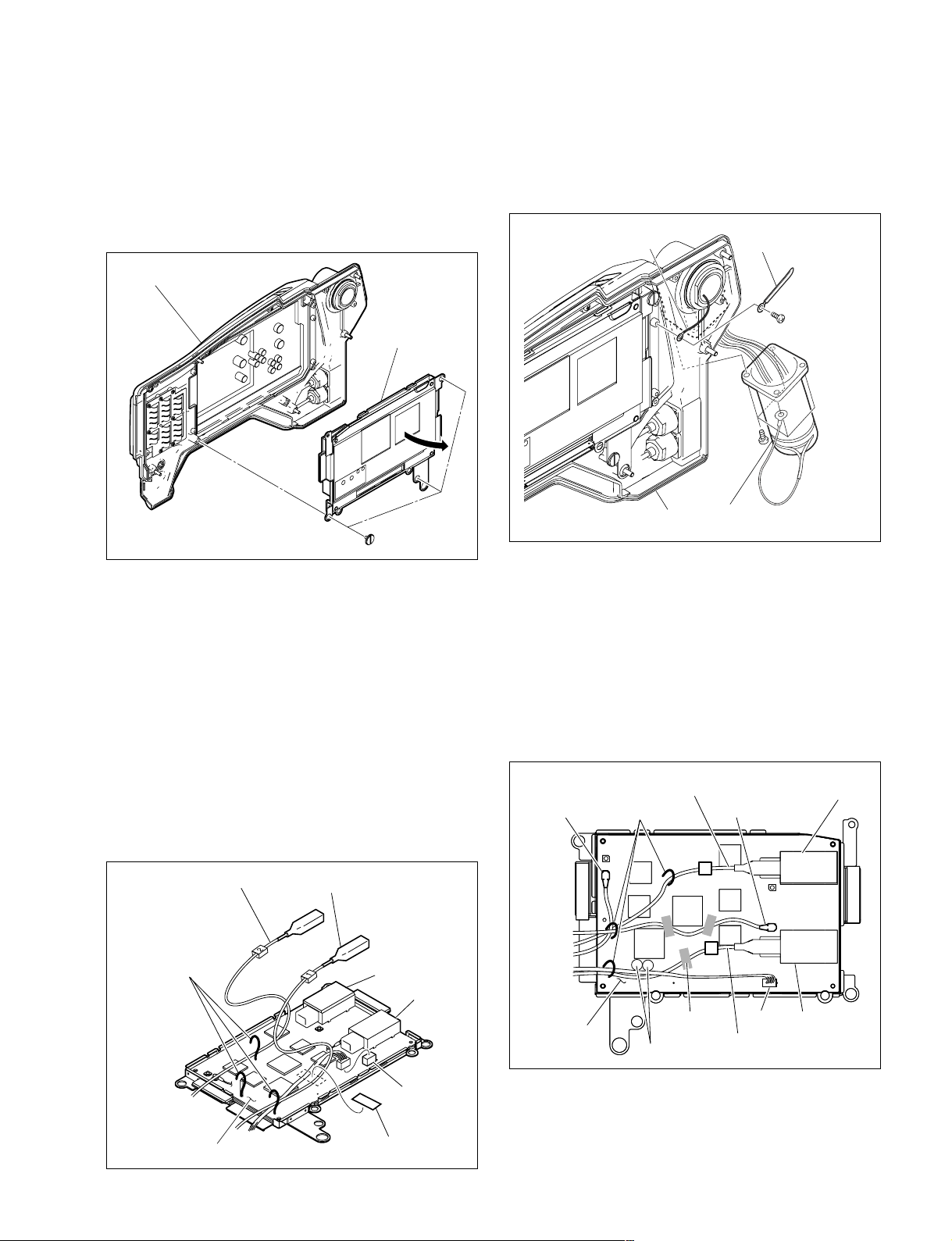
2-9-2. HDC1400/1500/1580 (Encapsulated
B2.6 x 5
Harness clamp
Lug
Outside panel
Encapsulated cable assembly
B3 x 8
Cable Assembly)
1. Remove the outside panel. (Refer to Section 1-4.)
2. Remove the three screws of the SDI unit, and open it
in the arrow direction.
Outside panel
SDI unit
Screws of
SDI unit
7. Remove the screw to detach the harness clamp and the
lug.
8. Remove the four screws, and pull out the encapsulated
cable assembly.
3. Remove the UL tape from the SDI-84/84C board.
4. Release the harness and cables from the three harness
clamps.
5. Disconnect the harness from the connector (CN102)
on the SDI-84/84C board.
6. Disconnect the optical fiber cables from the E/O
converter module CP201 and O/E converter module
CP401 on the SDI-84/84C board.
m
. If optical fiber cable is bent or pulled strongly, it
may be disconnected. Handle optical fiber cables
carefully.
. Do not touch the tip of optical fiber cable connector.
This may result in deterioration of signals.
Optical fiber cable (No.2)
Harness clamps
Optical fiber cable (No.1)
CP401
CP201
9. Install the encapsulated cable assembly by reversing
the steps above.
m
. Check cable numbers when connecting optical fiber
cables, and insert the cable connector as far as it will
go.
. Arrange the harness and cables as shown below, and
clamp them with the three harness clamps and UL
tape.
Coaxial cable
(black)
SDI-84/84C
board
Optical fiber cable (No.2)
Harness clamps
UL tape
Capacitors
Optical fiber cable (No.1)
Coaxial cable (white)
2
1
CN102
CP401
CP201
HDC1000/V1(E)
SDI-84/84C board
CN102
UL tape
. When connecting the optical fiber cables to the E/O
converter module CP201 or O/E converter module
CP401 on the SDI-84/84C board, clean the connecting connectors. (Refer to Section 1-8.)
2-19
Page 64
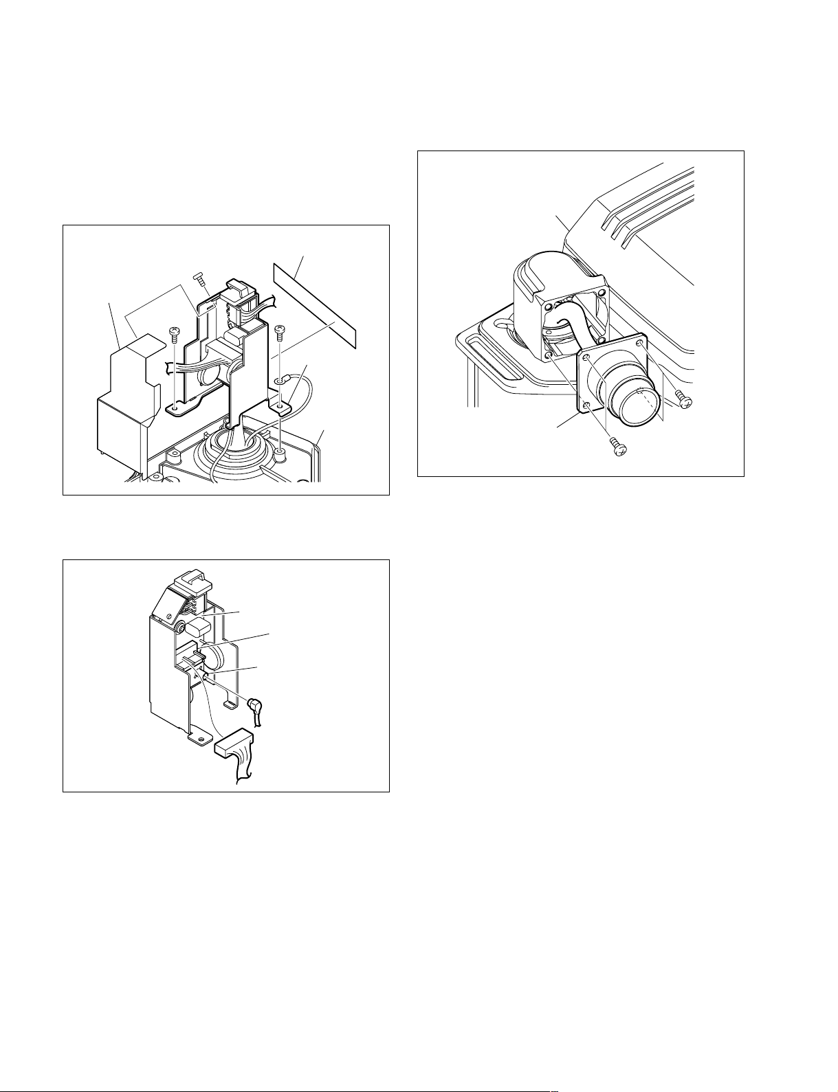
2-9-3. HDC1550 (TRIAX Assembly)
1. Remove the outside panel. (Refer to Section 1-4.)
2. Peel the UL tape off.
3. Remove the screw to detach the FL cover.
4. Remove the two screws, and lift the FL base up.
UL tape
B2.6 x 5
FL cover
B2.6 x 5
B2.6 x 5
FL base
6. Remove the four screws, and pull out the TRIAX
assembly.
Outside panel
Outside panel
5. Disconnect the harness and coaxial cable from the
connectors (CN1, CN2) on the FL-337 board.
FL-337 board
CN1
CN2
B3 x 8
TRIAX assembly
B3 x 8
7. Install the TRIAX assembly by reversing the steps
above.
n
Replace the UL tape with new one.
2-20
HDC1000/V1(E)
Page 65
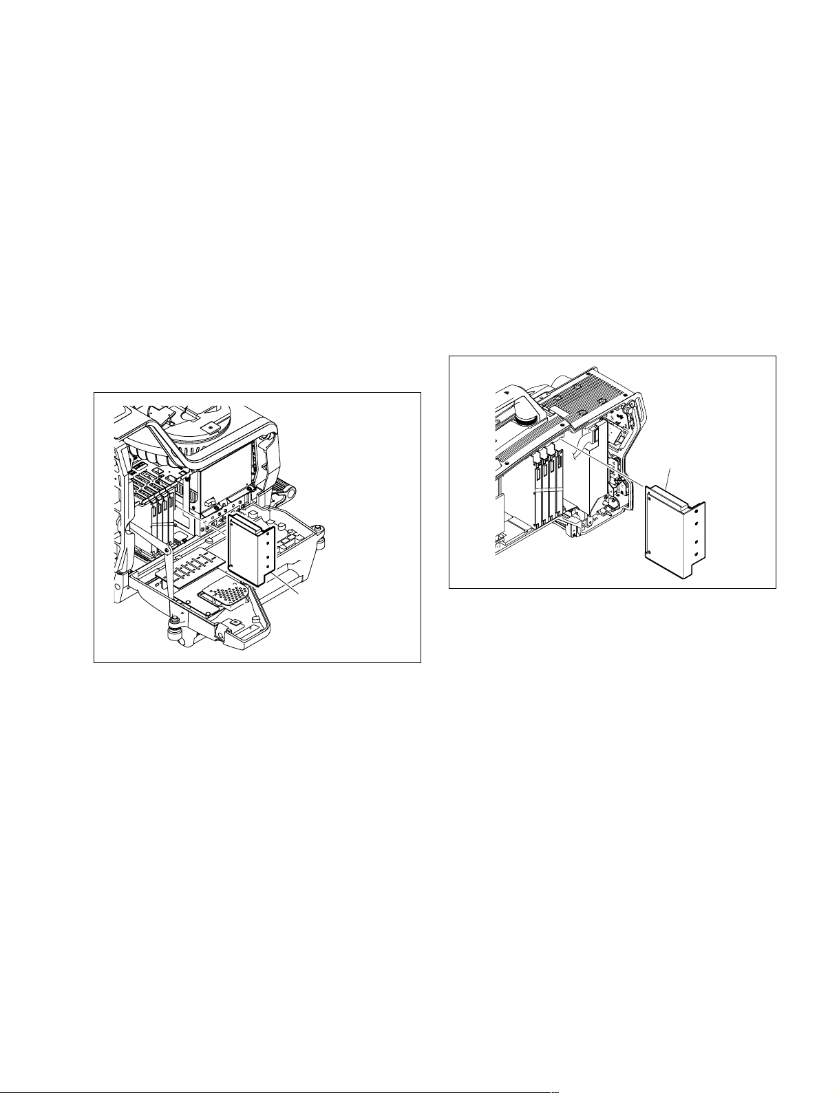
2-10. Replacing the DC/DC Converter Unit
2-10-2. HDC1400/1500/1550/1580
2-10-1. HDC1000
w
The DC/DC converter unit is a critical part for safety. If it
is replaced with an unspecified part, a fire or electric shock
may be caused.
Be sure to use the specified DC/DC converter unit below
for replacement.
CONVERTER UNIT, DC-DC: ! 1-478-790-11
1. Open the right side panel. (Refer to Section 1-4.)
2. Draw the DC/DC converter unit along the board rail
groove, and remove it.
w
The DC/DC converter unit is a critical part for safety. If it
is replaced with an unspecified part, a fire or electric shock
may be caused.
Be sure to use the specified DC/DC converter unit below
for replacement.
CONVERTER UNIT, DC-DC: ! 1-478-790-11
1. Remove the inside panel. (Refer to Section 1-4.)
2. Draw the DC/DC converter unit along the board rail
groove, and remove it.
DC-DC converter
DC-DC converter unit
3. Install the DC/DC converter unit by reversing the steps
above.
3. Install the DC/DC converter unit by reversing the steps
above.
HDC1000/V1(E)
2-21
Page 66
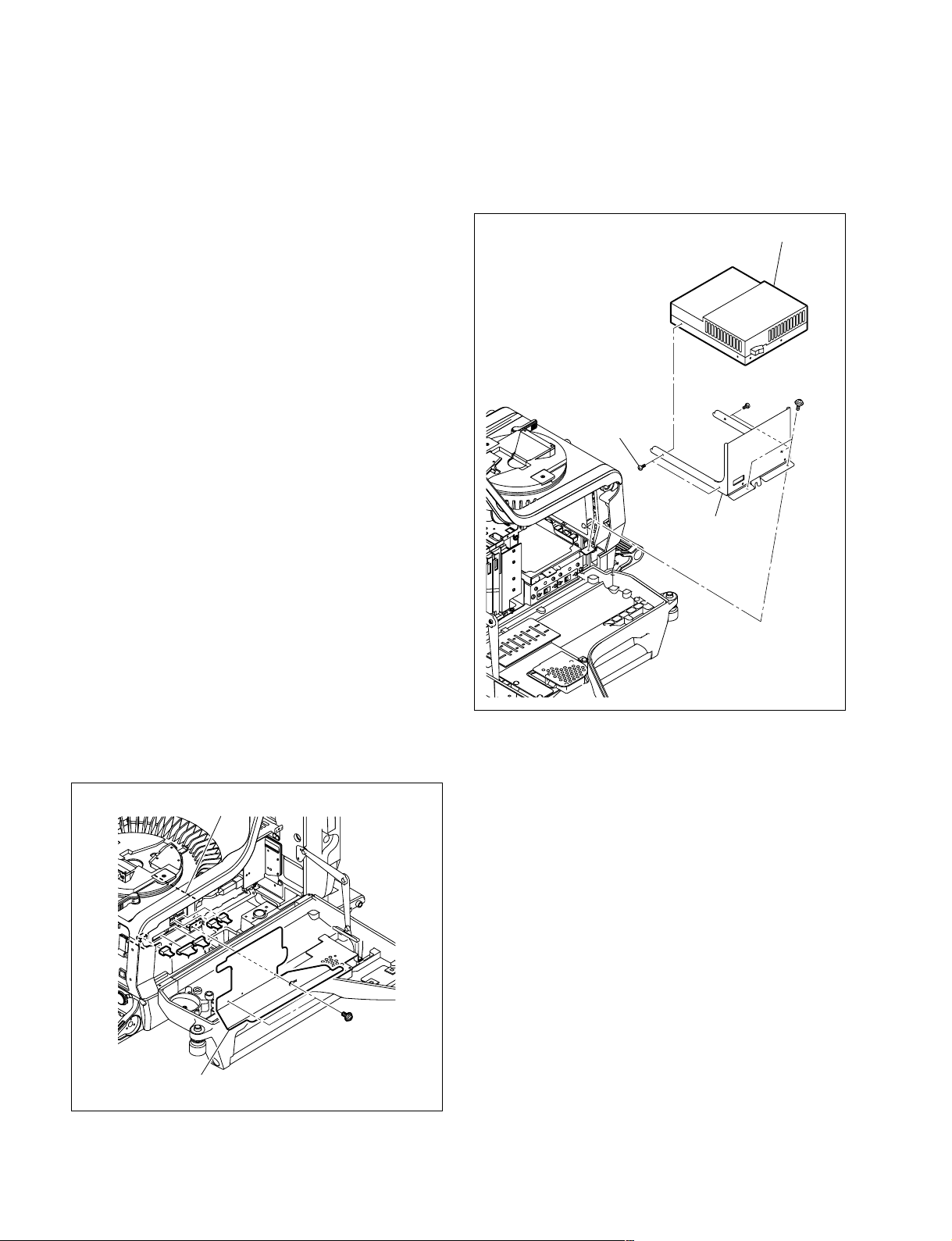
2-11. Replacing the Switching Regulator
2-11-1. HDC1000
w
The switching regulator is a critical part for safety. If it is
replaced with an unspecified part, a fire or electric shock
may be caused.
Be sure to use the specified switching regulator below for
replacement.
REGULATOR, SWITCHING: ! 1-468-861-11
4. Remove the two screws, and remove the power unit
bracket.
5. Remove the four screws, and remove the switching
regulator from the power unit bracket.
Switching regulator
m
. To avoid electric hazards when disconnecting the power
assembly, allow at least three minutes after powering off.
To turn off the power, disconnect the optical cable or the
cable connected to the DC IN connector in addition to
turning off the power switch.
. The power assembly will go very hot during operation. If
you touch the power assembly, there is some danger to
get burned.
When you repair power supply and peripheral equipment, allow a few minutes after powering off until the
inside cools off.
1. Open the right side panel and left side panel.
(Refer to Section 1-4.)
2. Remove the two screws, and remove the harness
guard.
3. Disconnect the harnesses from the five connectors on
the power assembly.
Power assembly
PWH
Screws (M2.6)
Screws (M2.6)
Power unit bracket
3 x 5
6. Install the switching regulator by reversing the steps
above.
2-22
PWH3 x 5
Harness guard
HDC1000/V1(E)
Page 67
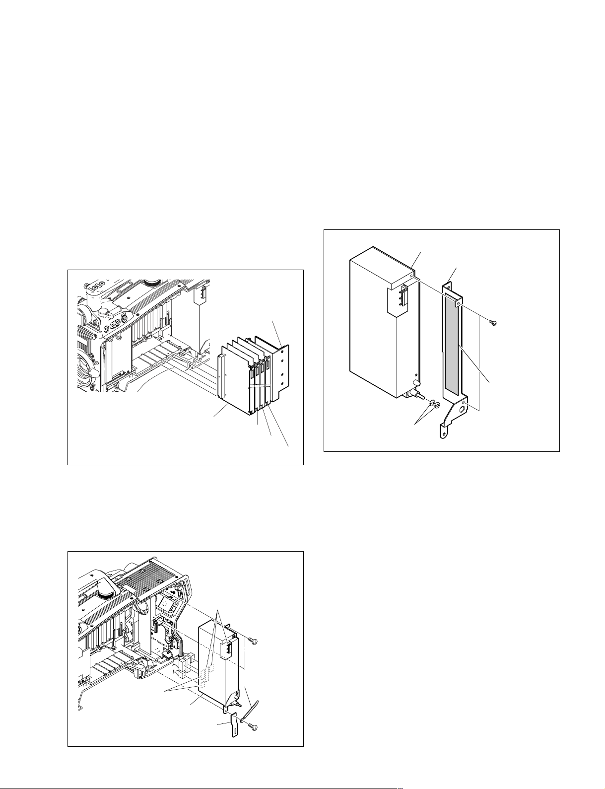
2-11-2. HDC1400/1500/1580
w
The switching regulator is a critical part for safety. If it is
replaced with an unspecified part, a fire or electric shock
may be caused.
Be sure to use the specified switching regulator below for
replacement.
REGULATOR, SWITCHING: ! 1-468-862-11
1. Remove the inside panel and outside panel.
(Refer to Section 1-4.)
2. Draw all the plug-in boards and the DC/DC converter
unit along the board rail grooves and remove them.
DC-DC converter unit
5. Remove the two screws to detach the power supply
bracket from the switching regulator.
m
. There is the thermattach tape (AC/DC) between the
switching regulator and power supply bracket.
Detach the power supply bracket slowly and surely.
. Replace the thermattach tape (AC/DC) with new
one.
6. Remove the two poron sheets from the switching
regulator.
Switching regulator
Power supply bracket
B2.6 x 5
VDA-63 board
DAP-33 board
AU-298 board
AT-163 board
3. Disconnect the harnesses from the five connectors on
the switching regulator.
4. Remove the three screws, and remove the switching
regulator, hanging band (REAR), and the harness
clamp.
Connectors
B2.6 x 5
Thermattach
tape (AC/DC)
Poron sheets
7. Install the switching regulator by reversing the steps
above.
HDC1000/V1(E)
Connectors
Harness clamp
Switching regulator
Hanging band (REAR)
B2.6 x 5
2-23
Page 68
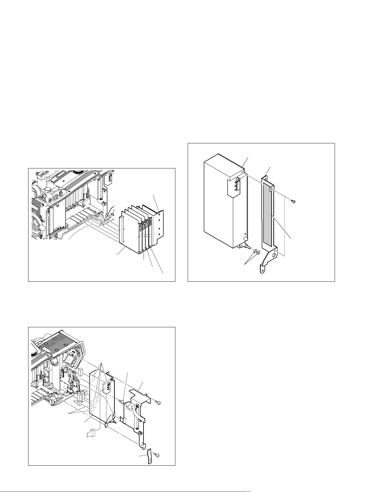
2-11-3. HDC1550
w
The switching regulator is a critical part for safety. If it is
replaced with an unspecified part, a fire or electric shock
may be caused.
Be sure to use the specified switching regulator below for
replacement.
REGULATOR, SWITCHING: ! 1-468-862-11
1. Remove the inside panel and outside panel.
(Refer to Section 1-4.)
2. Draw all the plug-in boards and the DC/DC converter
unit along the board rail grooves and remove them.
DC-DC converter unit
5. Remove the two screws to detach the power supply
bracket from the switching regulator.
m
. There is the thermattach tape (AC/DC) between the
switching regulator and power supply bracket.
Detach the power supply bracket slowly and surely.
. Replace the thermattach tape (AC/DC) with new
one.
6. Remove the two poron sheets from the switching
regulator.
Switching regulator
Power supply bracket
B2.6 x 5
VDA-63 board
DAP-33 board
AU-298 board
AT-163 board
3. Disconnect the harnesses from the six connectors on
the switching regulator.
4. Remove the three screws, and remove the switching
regulator, FL bracket, and hanging band (REAR).
Connectors
B2.6 x 5
FL bracket
B2.6 x 5
Connectors
Thermattach
tape (AC/DC)
Poron sheets
7. Install the switching regulator by reversing the steps
above.
2-24
Switching regulator
B2.6 x 5
Hanging band (REAR)
HDC1000/V1(E)
Page 69
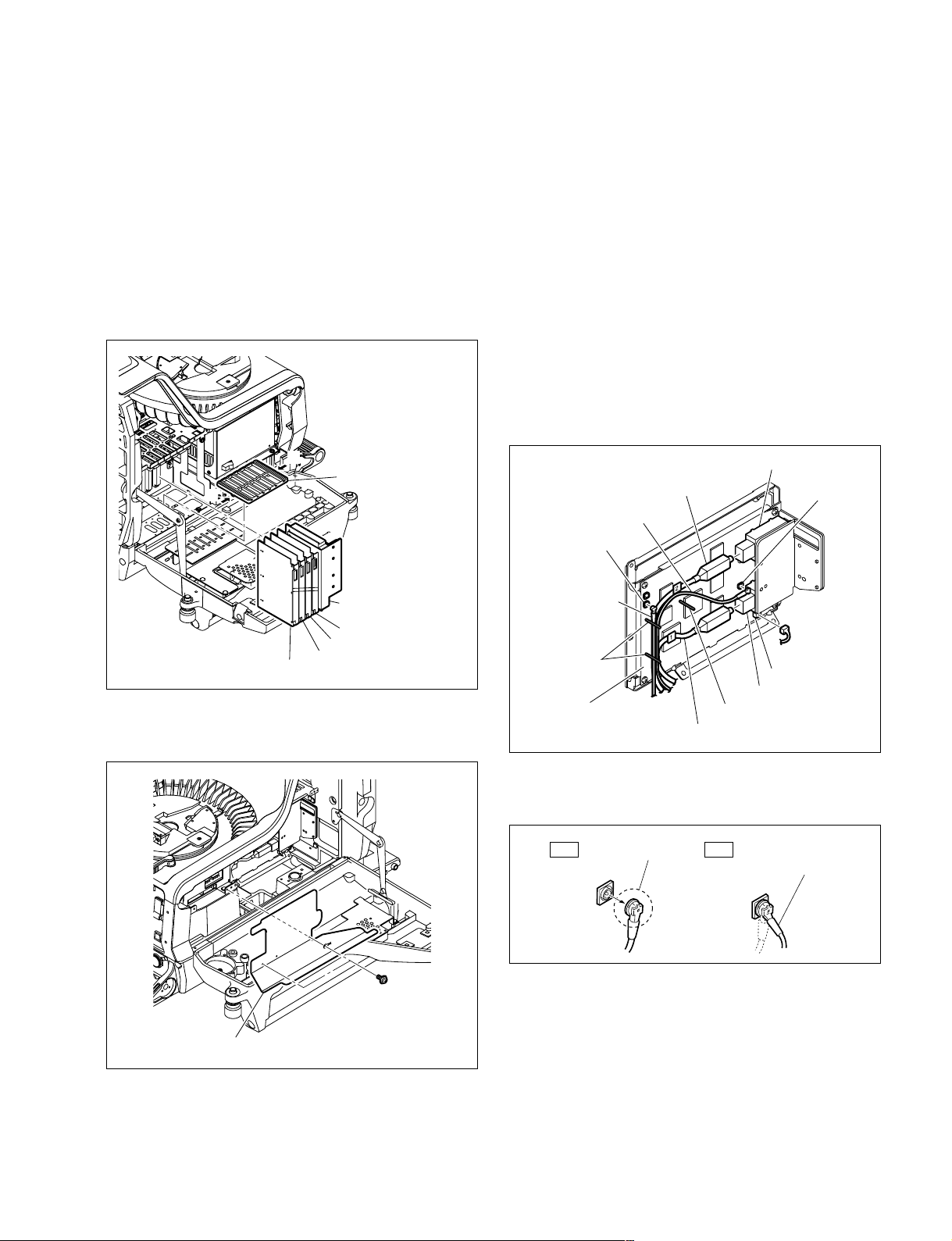
2-12. Replacing the Boards (HDC1000)
2-12-1. MB-1060 Board
1. Open the right side panel and left side panel.
(Refer to Section 1-4.)
2. Draw all the plug-in boards and the DC/DC converter
unit along the board rail grooves and remove them.
3. Remove the board rail while pushing the portions A of
the board rail.
5. Release the harness and cables from the three harness
clamps.
6. Disconnect the coaxial cables from the connectors
(CN201, CN851) on the SDI-84 board.
7. Disconnect the harness from the connector (CN102)
on the SDI-84 board.
8. Disconnect the optical fiber cables from the E/O
converter module CP201 and O/E converter module
CP401 on the SDI-84 board.
m
. If optical fiber cable is bent or pulled strongly, it
may be disconnected. Handle optical fiber cables
carefully.
. Do not touch the tip of optical fiber cable connector.
This may result in deterioration of signals.
A
Board rail
A
DC-DC converter unit
AT-163 board
AU-298 board
VDA-63 board
DAP-33 board
4. Remove the two screws, and remove the harness
guard.
CP401
Coaxial cable (brown)
CN851
Coaxial cable
(green)
Harness clamp
SDI-84 board
Optical fiber cable
CP201
Harness clamp
Optical fiber cable
CN201
CN102
. Be sure to hold the plug when disconnecting the
coaxial cable. Do not pull the cable.
Hold the plug to
OK NG
remove.
Do not attempt to
remove by pulling
the cable.
HDC1000/V1(E)
PWH3 x 5
Harness guard
2-25
Page 70
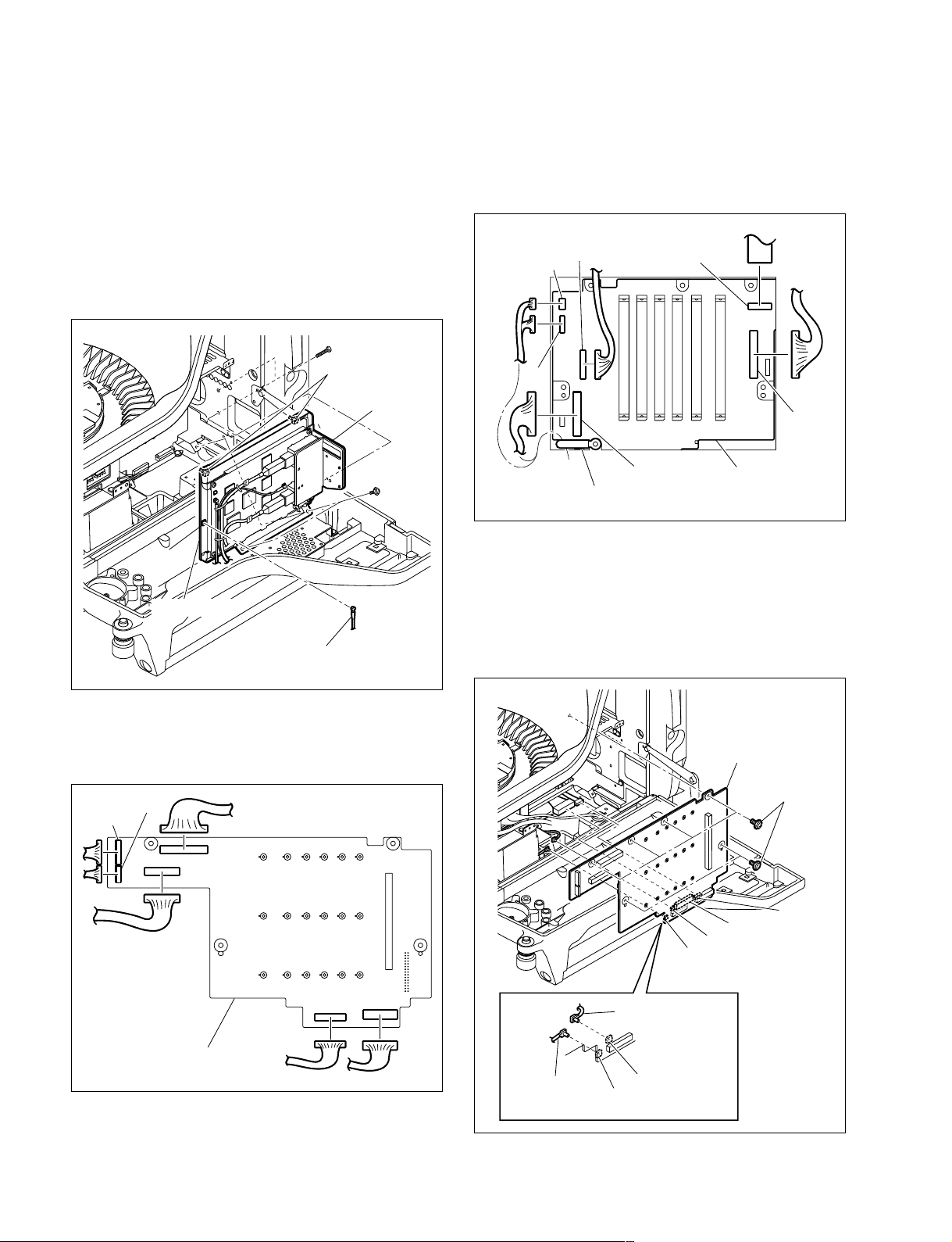
9. Loosen the two screws with stopper.
n
There is the model for which the normal screws
(PSW3 x 6) are used, too.
10. Remove the four screws, and remove the SDI unit
assembly.
11. Disconnect the coaxial cable from the connector
(CN601) on the DPR-265 board.
B3 x 10
Screws with
stopper/
PSW3 x 6
SDI unit
assembly
13. Release the harness from the harness clamp.
14. Disconnect the harness and flexible card wire from the
connectors (CN2, CN3, CN6, CN7, CN14, and CN17)
on the MB-1060 board (side A).
CN3
CN2
CN7
CN6
CN14
PSW3 x 6
CN601
DPR-265 board
Coaxial cable (red)
12. Disconnect the harness from the connectors (CN10,
CN11, CN13, CN15, CN16, and CN27) on the MB1060 board (side B).
CN16
CN15
CN10
CN13
CN17
Harness clamp
MB-1060 board
(side A)
15. Remove the six screws, and remove the MB-1060
board.
16. Disconnect the harness from the connectors (CN4,
CN9) on the MB-1060 board.
17. Disconnect the coaxial cables from the connectors
(CN28, CN29) on the MB-1060 board.
MB-1060 board
PSW3 x 6
CN4
CN29
CN28
CN9
2-26
MB-1060 board
(side B)
CN11
CN27
Coaxial cable
(yellow)
Coaxial cable
(orange)
CN29
CN28
HDC1000/V1(E)
Page 71
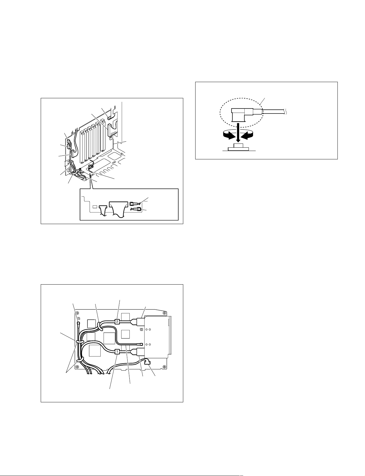
18. Install the MB-1060 board by reversing the steps
above.
m
. Arrange the harness, cables and flexible card wire on
the MB-1060 board (side A) as shown below, and
clamp them with the harness clamp.
CN6
CN14
CN2
CN3
CN7
MB-1060 board
(side A)
. Hold the plug of the coaxial cable, and connect it
perpendicularly to the connector.
Push the plug into the connector while turning it
clockwise and counterclockwise several times.
Hold the plug to connect
Connecting connector
CN17
Harness clamp
CN9
CN9
CN4
CN4
CN29
CN28
Coaxial cable
(orange)
Coaxial cable
(yellow)
. Check cable numbers when connecting optical fiber
cables, and insert the cable connector as far as it will
go.
. Arrange the harness and cables on the SDI-84 board
as shown below, and clamp them with the three
harness clamps.
Coaxial cable
(green)
SDI-84
board
Harness clamp
Optical fiber cable (No.2)
CP401
. When connecting the optical fiber cables to the E/O
converter module CP201 or O/E converter module
CP401 on the SDI-84 board, clean the connecting
connectors. (Refer to Section 1-8.)
Harness clamps
HDC1000/V1(E)
Coaxial cable (brown)
Optical fiber cable (No.1)
CP201
CN102
2-27
Page 72
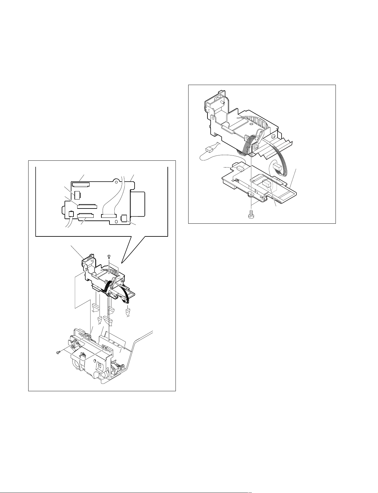
2-13. Replacing the Boards (HDC1400/
1500/1550/1580)
2-13-1. CN-2617 Board
1. Remove the inside panel and outside panel.
(Refer to Section 1-4.)
2. Remove the DC fan (front). (Refer to Section 2-5-1.)
3. Remove the four screws, and lift the sub frame
assembly.
4. Disconnect the harnesses from the connectors (CN2,
CN3, CN7, CN8, and CN9) on the CN-2617 board,
and remove the sub frame assembly.
5. Disconnect the harnesses from the connectors (CN4,
CN5) on the CN-2617 board.
6. Remove the two screws, and remove the CN-2617
board.
CN2
CN8
CN9
CN7
Sub frame assembly
B2.6 x 5
CN-2617 board
CN3
CN5
B2 x 4
CN-2617 board
CN4
7. Install the CN-2617 board by reversing the steps
above.
2-28
B2.6 x 5
HDC1000/V1(E)
Page 73
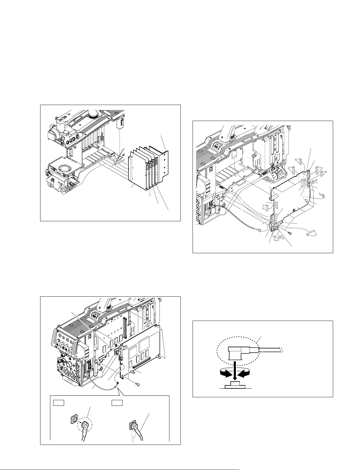
2-13-2. MB-1059 Board
1. Remove the inside panel and outside panel.
(Refer to Section 1-4.)
2. Remove the front assembly. (Refer to Section 2-1.)
3. Draw all the plug-in boards and the DC/DC converter
unit along the board rail grooves and remove them.
DC-DC converter unit
6. Disconnect the harnesses and flexible card wires from
all the connectors on the MB-1059 board.
n
Life of flexible card wire will be significantly shortened if it is folded. Be very careful not to fold the
flexible card wires. (Refer to Section 1-10.)
7. Remove the eight screws, and remove the MB-1059
board.
MB-1059 board
CN1
VDA-63 board
DAP-33 board
AU-298 board
AT-163 board
4. Disconnect the coaxial cable from the connector
(CN601) on the DPR-265 board.
n
Be sure to hold the plug when disconnecting the
coaxial cable. Do not pull the cable.
5. Remove the four screws to detach the DPR-265 board
and FL holder (HDC1550 only).
FL holder
(HDC1550 only)
CN11
CN3
CN17
CN12
CN18
CN15
CN6
CN13
CN14
B2 x 4
CN16
8. Install the MB-1059 board by reversing the steps
above.
n
Hold the plug of the coaxial cable, and connect it
perpendicularly to the connector.
Push the plug into the connector while turning it
clockwise and counterclockwise several times.
Hold the plug to connect
CN2
CN7
CN4
Coaxial cable
Hold the plug to
OK NG
remove.
HDC1000/V1(E)
CN601
DPR-265 board
Connecting connector
B2.6 x 5
Do not attempt to
remove by pulling
the cable.
2-29
Page 74
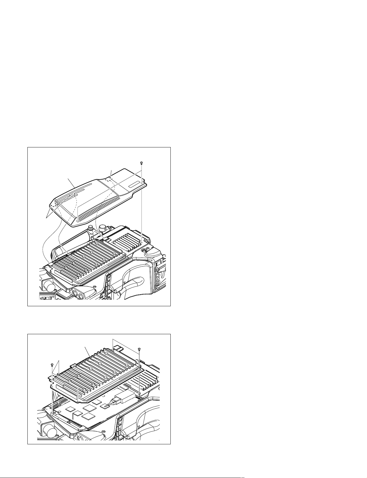
2-14. Checking SDI-84 Board (HDC1400/
1500/1580)
To check the operation of the SDI-84 board and to upgrade
the PLD, perform preprocessing using the following
procedure to ensure the service position for the SDI-84
board.
1. Remove the two screws, release the three claws on the
outside pad subassembly from the holes in the heatsink
subassembly, and then remove the outside pad subassembly.
B2.6 x 5
Claw
Outside pad subassembly
Claws
2. Remove the five screws and the heatsink subassembly.
3. The SDI-84 board appears.
Heatsink subassembly
B2.6 x 5
B2.6 x 5
2-30
HDC1000/V1(E)
Page 75

Section 3
Electrical Alignment
When any board of HDC1000/1400/1500/1550/1580 is
repaired or replaced, perform electrical adjustments as
follows.
HDC1000/1400/1500/1580
Section 3-1 to 3-5
HDC1550
Section 3-1 to 3-9
m
. Perform video system level adjustment (Section 3-4)
according to customer needs.
. One of master setup units MSU-900, etc. is used for
electrical adjustments of the unit.
Refer to Section 3-1-8 when using the camera setup
menu for electrical adjustments without using MSU-900.
3-1. Preparations
3-1-1. Equipment Required
Measuring equipment
. HDTV serial digital waveform monitor
Leader Electronics LV5150DA, Leader Electronics
LV5152DA (multi format) or equivalent
. HD color monitor
Sony BVM-D20F1/BVM-D14H5 or equivalent
. Oscilloscope
Tektronix TDS460A or equivalent
Related Equipment
. HDVS camera system
MSU-700A/750/900/950
HDVF-20A (For HDC1500/1550)
HDVF-700A (For HDC1000)
HDCU1080 (When adjusting the HDC1580, use this
unit)
. Lens
Canon HJ18
3-1-2. Precautions on Adjustments
. Turn ON the main power switch (external) before
adjusting, and warm up the unit for about 10 minutes.
. All measuring equipment must be calibrated.
. Periodic Maintenance must be conducted for the pattern
box.
. “Section 3-1-7. Initial Settings” must be completed.
. For HDC1580 adjustment, connect the measuring
waveform monitor to the SDI 1 connector of
HDCU1080. Set the HDCU1080 so that the HD-SDI
signal is outputted from the SDI 1 connector.
3-1-3. File Data at Adjustment
The file structure of the adjustment data of HDC1000/
1500/1550/1580 is as follows.
Scene
Lens
Reference
OHB
File data
. Lens file is used for compensation of the deviation
which is generated by switching the lens extender from
OFF to ON and for compensation of the difference in the
characteristics between lenses. This file is stored in the
camera. Mount the lens actually used during the adjustment.
. The reference file stores the custom paint data adjusted
by the video engineer. This file is stored in the camera
and memory stick. Therefore, before performing adjustment, store this data in the memory stick first, and reset
this data from the memory stick after adjustment.
. OHB file is used for adjustment of the CCD block
maintenance. This file is stored in the camera.
Total adjustment data
Tools
. Pattern box PTB-500
Sony Part No. : J-6029-140-B
. Grayscale chart (16 : 9 transparent type)
Sony Part No. : J-6394-080-A
. Grayscale chart (4 : 3 reflective type)
Commercially available
HDC1000/V1(E)
3-1
Page 76
3-1-4. Maintaining the Grayscale Chart
For the adjustment, using an 89.9 %-reflective grayscale chart is preferable.
If a reflective chart is not available, use a well-maintained pattern box and a transparent grayscale chart
for adjustment.
Before beginning adjustment, set the illumination of the light source (or the luminous intensity on the
chart surface) properly proceeding as follows and set the color temperature to 3200 K exactly by adjusting light.
Information on the reflective grayscale chart (16 : 9)
Recommended chart
The reflective grayscale chart (16 : 9) is commercially available.
Recommended chart: Reflective grayscale chart
Supplier: MURAKAMI COLOR RESEARCH LABORATORY
Handling precautions
. Do not touch the chart’s surface.
. Do not subject the surface to dirt, scratches or prolonged exposure to sunlight.
. Protect the chart from excessive moisture and harmful gas.
. Avoid resting articles against the case.
. When the chart is not used for a long period and is stored, open the case and dry the chart for about an
hour once or twice a month.
Replacement period when the chart is used as the reference
The reflective grayscale chart should be replaced every two years if it used as the reference. Because the
chart deteriorates with time and proper adjustment cannot be achieved.
Replacement period varies according to storage conditions of the chart.
Setting illumination (when the reflective chart is used)
Equipment: Illuminance meter (Calibrated)
Chart
1. Turn on the light source and warm up for about 30
minutes.
Illuminance meter Light source
2. Place the illuminance meter on the chart surface.
Adjust the position and angle of the light source so that
the whole surface of the chart is evenly 2000 lx.
n
Light the chart from almost the same direction and
height as the camera to shoot the chart.
3-2
HDC1000/V1(E)
Page 77
Setting luminous intensity (when the transparent chart is used)
Equipment: Luminance meter (Minolta LS-110 or equivalent. Calibrated.)
1. Light the pattern box and warm up for about 30 minutes.
2. Place the pattern box where the chart is not exposed to light, such as a darkroom.
(Or cover the pattern box with a cover whose inside is painted in black.)
3. Place the luminance meter facing straight to the chart at a distance of 1 m from it.
4. Adjust the luminance control of the pattern box so that the white portion in the center of the chart is
573 ± 6 cd/m2.
n
This corresponds to the luminous intensity on the 89.9 %-reflective chart at 2000 lx.
Chart
Luminance meter
1 m
HDC1000/V1(E)
3-3
Page 78

3-1-5. Description on Setup Menu
How to change the setting values
Some of adjustments given in this section use the setup
menu. The setup menu consists of the following menus.
Besides there is a TOP menu indicating the entire configuration of menu items.
. USER menu
. USER MENU CUSTOMIZE menu
. OPERATION menu
. PAINT menu
. MAINTENANCE menu
. FILE menu
. DIAGNOSIS menu
. SERVICE menu
In this section, describes the setup menu operation as
follows.
For example:
When AUTO LEVEL in AUTO SETUP page of MAINTENACE menu is performed:
MENU: MAINTENANCE
PAGE: AUTO SETUP
ITEM: AUTO LEVEL
How to display the SERVICE menu
HDC1000
Set the DISPLAY switch to “MENU” while pressing the
ASSIGNABLE switch and the MENU SELECT switch
(ENTER side).
To enter or cancel the setting value of items, which can be
changed by turning the MENU SELECT control
(HDC1000) or rotary encoder (HDC1500/1550/1580),
proceed as follows.
HDC1000
To enter the setting value:
Press the MENU SELECT switch toward the “ENTER” side.
To cancel the setting value:
Before pressing the MENU SELECT switch toward
the “ENTER” side, press the MENU SELECT switch
toward the “CANCEL” side. The original setting is
restored.
After the MENU SELECT switch is pressed toward
the “ENTER” side, the setting cannot be canceled.
HDC1400/1500/1550/1580
To enter the setting value:
Press the rotary encoder.
To cancel the setting value:
Before pressing the rotary encoder, press the MENU
switch toward the “CANCEL” side. The original
setting is restored.
After the rotary encoder is pressed, the setting cannot
be canceled.
HDC1400/1500/1550/1580
Set the DISPLAY switch to “MENU” while pressing the
ASSIGNABLE switch and the rotary encoder.
3-4
HDC1000/V1(E)
Page 79
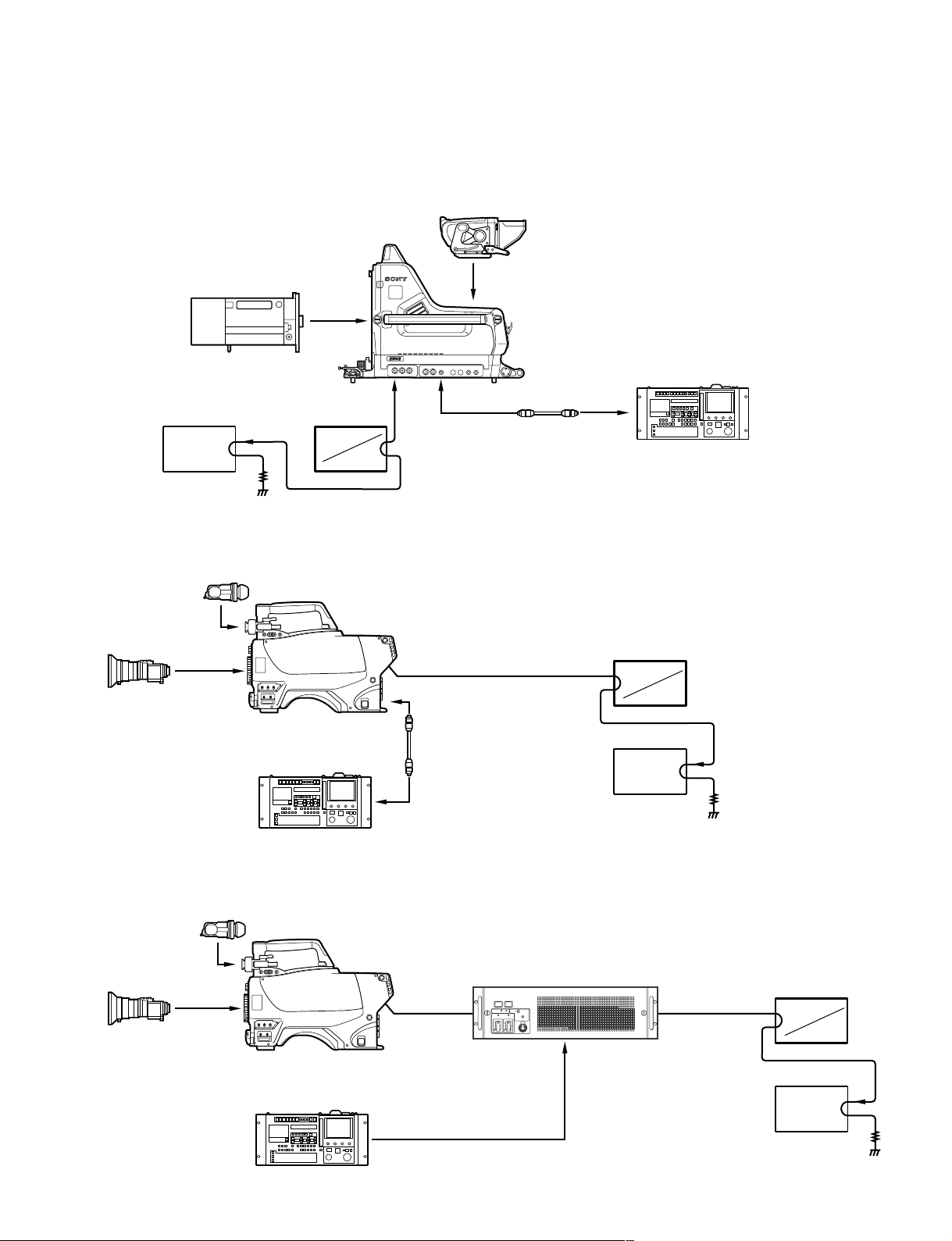
3-1-6. Connection of Equipment
HDC1000
HDVF-700A
LENS
Color monitor
75 Z
HDC1400/1500/1550
2" VF
HDVF-20A
ENG/EFP
LENS
Waveform monitor
Y, Pb, Pr
R, G, B
HD CAMERA
HDC1400/1500/1550
1
REMOTESDI 1
A-ch
SDI 1 (HDC1500)
SDI (HDC1400/1550)
REMOTE
HD CAMERA
HDC1000
CCA-5 CABLE
(max. 200 m)
MASTER SETUP UNIT
MSU-700A/750/900/950
Waveform monitor
A-ch
Y, Pb, Pr
R, G, B
HDC1580
ENG/EFP
LENS
2" VF
HDVF-20A
MASTER SETUP UNIT
MSU-700A/750/900/950
HD CAMERA
HDC1580
MASTER SETUP UNIT
MSU-700A/750/900/950
CCA-5 CABLE
(max. 200 m)
OPTICAL
FIBER
CABLE
Color monitor
HDCU1080
RCP/CNU connector (8-pin)
SDI 1
OUTPUT
*
Set to HD SDI
75 Z
Waveform monitor
*
A-ch
Y, Pb, Pr
R, G, B
Color monitor
75 Z
HDC1000/V1(E)
3-5
Page 80

3-1-7. Initial Settings
When adjusting using the Setup menu
n
In this section, describes the adjustment procedures using
MSU-900.
MSU control panel
When MSU-700A/900 is used
. Power supply and signal switching block
ALL button → OFF (dark)
CAM PW button → ON (lit)
VF PW button → ON (lit)
TEST 1 button → OFF (dark)
TEST 2 button → OFF (dark)
BARS button → OFF (dark)
CLOSE button → ON (lit)
. Camera/CCU circuit ON/OFF block
KNEE OFF button → OFF (lit)
DETAIL OFF button → OFF (lit)
LVL DEP OFF button → OFF (lit)
MATRIX OFF button → OFF (lit)
AUTO KNEE button → OFF (dark)
SKIN DETAIL button → OFF (dark)
. Others
GAMMA OFF button → ON (dark)
MASTER GAIN → 0 (0 dB)
FILTER(ND) button → 1 (CLEAR)
FILTER(CC) button → B (3200K)
ECS/SHUTTER ON button → OFF (dark)
When MSU-750/950 is used
. Power supply and signal switching block
ALL button → OFF (dark)
CAM PW button → ON (lit)
VF PW button → ON (lit)
TEST button → OFF (dark)
BARS button → OFF (dark)
CLOSE button → ON (lit)
. Camera/CCU circuit ON/OFF block
Knee Off
Detail Off
Level Dep Off
Matrix Off
*
*
*
*
→ OFF (lit in reverse)
→ OFF (lit in reverse)
→ OFF (lit in reverse)
→ OFF (lit in reverse)
AUTO KNEE button → OFF (dark)
SKIN DETAIL button → OFF (dark)
. Others
Gamma Off
Master Gain
ND (1/2/3/4/5)
CC (A/B/C/D/E)
ECS/Shutter
*: Push the FUNCTION button, then select the function menu display.
*
*
*
*
*
→ ON (lit normally)
→ 0 (0 dB)
→ 1 (CLEAR)
→ B (3200K)
→ OFF (lit normally)
3-6
. PAINT menu
Page Setting item Initial setting
SW STATUS FLARE ON
GAMMA ON
BLK GAM OFF
KNEE OFF
WHT CLIP OFF
DETAIL ON
LVL DEP ON
SKIN DTL OFF
MATRIX OFF
VIDEO LEVEL TEST OFF
Side panel (HDC1400/1500/1550/1580):
GAIN switch → L (0 dB)
OUTPUT/AUTO KNEE switch → CAM/OFF
WHITE BAL switch → PRST
Front panel (HDC1500/1550):
SHUTTER switch → OFF
FILTER LOCAL button + ND button → 1 (CLEAR)
FILTER LOCAL button + CC button → B (3200 K)
Front panel (HDC1400/1580):
SHUTTER switch → OFF
FILTER LOCAL button + ND button → 1 (CLEAR)
HDC1000/V1(E)
Page 81

3-1-8. Adjustment Items and Setup Menu Items
Refer to the following table when using the camera setup menu for electrical adjustments without using MSU-900.
The table shows camera menu items corresponding to adjustment items of MSU-900.
Maintenance menu (MAINTENANCE button/MSU-900
Menu item of the MSU-900 Menu item of the camera
Menu Secondary menu Sub menu Adjusting item MENU PAGE ITEM
Adjusting White Shading R/G/B H Saw MAINTENANCE WHITE SHADING H SAW R/G/B
H Para H PARA R/G/B
V Saw V SAW R/G/B
V Para V PARA R/G/B
Auto Setup Auto Level MAINTENANCE AUTO SETUP AUTO LEVEL
Lens Adjusting V Mod Saw R/G/B PAINT VIDEO LEVEL V MOD R/G/B
Auto Iris Level MAINTENANCE AUTO IRIS IRIS LEVEL
APL Ratio APL RATIO
File control menu (FILE button/MSU-900
Menu item of the MSU-900 Menu item of the camera
Menu Sub menu MENU PAGE ITEM
Reference Ref Store FILE REFERENCE STORE FILE
Lens File Lens Store LENS FILE STORE FILE
OHB File OHB Store OHB FILE STORE FILE
→→
→ ON (lit))
→→
→→
→ ON (lit))
→→
Paint menu page 1/3 (PAINT button/MSU-900
Menu item of the MSU-900 Menu item of the camera
Menu Sub menu Adjusting Item MENU PAGE ITEM
Black R/G/B/Master PAINT VIDEO LEVEL BLACK R/G/B/M
Flare R/G/B FLARE R/G/B
Detail Detail 1 Level DETAIL 1 LEVEL
Limiter LIMITER [M]
Crispning CLISP
Level Dep LVL DEP
Detail 2 H/V Ratio HV RATIO
Detail 3 W.Limiter LIMITER WHT
B.Limiter LIMITER BLK
Paint menu page 2/3 (PAINT button/MSU-900
Menu item of the MSU-900 Menu item of the camera
Menu Adjusting item MENU PAGE ITEM
Gamma R/G/B/Master PAINT GAMMA LEVEL R/G/B/M
Knee Point R/G/B/Master KNEE POINT R/G/B/M
Knee Slope R/G/B/Master SLOPE R/G/B/M
White Clip R/G/B/Master WHT CLP R/G/B/M
→→
→ ON (lit))
→→
→→
→ ON (lit))
→→
HDC1000/V1(E)
3-7
Page 82

3-2. Automatic Adjustment
3-3. Electrical Alignment
To execute the automatic adjustment
1. MSU menu operation:
. MAINTENANCE button → ON (lit)
. Touch panel operation
[Auto|Setup] → [Auto|Level]
n
When performing automatic adjustment using the
menu of the camera, set the setup menu as follows.
MENU: MAINTENANCE
PAGE: AUTO SETUP
ITEM: AUTO LEVEL
2. When the adjustment is completed, the message
“Completed” will be displayed.
3-3-1. Clamp Level Adjustment between
Channel A and Channel B
Preparations
. Menu setting
MENU : SERVICE
PAGE : OHB_ADJ1
Adjustment Procedure
1. Adjustment Item:
MENU: SERVICE
PAGE: OHB-ADJ1
ITEM: DC_ADJ_A [R1], [G1], [B1]
DC_ADJ_B [R1], [G1], [B1]
DC_ADJ_A [R2], [G2], [B2]
Specification:
For 1080_59.94i/50i/29.97PsF/25 PsF/
23.58 PsF, set “DC_ADJ_A [R1], [G1],
[B1]” and “DC_ADJ_B [R1], [G1], [B1]”
to 68.
For 1080_59.94P/50P, set “DC_ADJ_A
[R1], [G1], [B1]” and “DC_ADJ_A [R2],
[G2], [B2]” to 68. (This item is fine
adjusted during the RPN adjustment
described later.)
2. Execute file storing for each format.
MENU: SERVICE
PAGE: OHB-ADJ1
ITEM: STORE FILE
3-8
HDC1000/V1(E)
Page 83
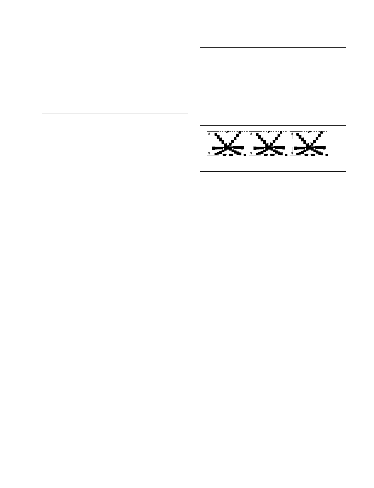
3-3-2. BLACK SET Adjustment
A
R1
R2
G1
G2
B1
B2
100%
B C
Adjustment Procedure
Preparation
. Setting for MSU-900
CLOSE button → ON (lit)
MASTER GAIN → 12
Adjustment Procedure
1. Adjustment Item:
MENU: SERVICE
PAGE: BLACK SHADING
ITEM: BLK SET [R], [G], [B]
Specification:
Adjust this using WFM so that the PED
level of each channel becomes equal within
a range of _3 to +12 dB.
2. Execute file storing for each format.
MENU: SERVICE
PAGE: BLACK SHADING
ITEM: STORE FILE
3-3-3. Sensitivity Adjustment
1. Adjustment Item:
MENU: SERVICE
PAGE: OHB_ADJ1
ITEM: GAIN_CONT [R1], [G1], [B1]
GAIN_CONT [R2], [G2], [B2]
(1080_59.94P/50P only)
Specification:
. For F1080_59.94i/50i/29.97PsF/25PsF/23.98PsF,
probe the R1/G1/B1 signals on the tool board by the
oscilloscope, and adjust “GAIN_CONT [R1], [G1],
[B1]” so that the “A” level becomes 176 ±5 mV.
. For 1080_59.94P/50P, probe the R1/G1/B1 and R2/
G2/B2 signals on the tool board by the oscilloscope,
and adjust “GAIN_CONT [R1], [G1], [B1], [R2],
[G2], [B2]” so that the “A” level becomes 105 ±5
mV.
Preparation
. MSU-900 setting
CLOSE button → OFF (dark)
GAMMA OFF button → OFF (lit)
MASTER GAIN → 0
DETAIL OFF button → OFF (lit)
. Turn ON (lighting) the TEST1 button to display the
TEST SAW waveform, and check that the amplitude is
700 mV using the WFM.
. If the amplitude is not 700 mV, adjust it by the follow-
ing.
MENU: SERVICE
PAGE: WHITE SHADING
ITEM: WHITE [R], [G], [B]
Then turn OFF (light off) the TEST1
button.
. Shoot the grayscale chart so that the chart frame is
aligned with the underscanned monitor frame.
. Lens iris: F10
* Use a lens with a transmittance equivalent to Canon
HJ18.
2. Execute file storing for each format.
MENU: SERVICE
PAGE: OHB_ADJ1
ITEM: STORE FILE
HDC1000/V1(E)
3-9
Page 84
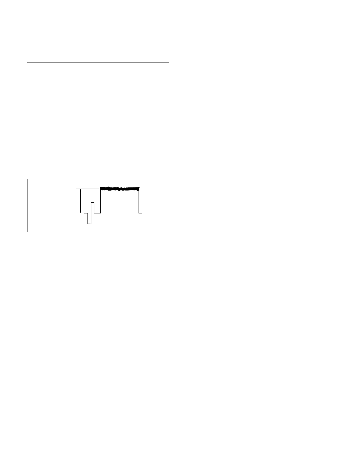
3-3-4. V-SUB Adjustment
Preparation
. Setting for MSU-900
MASTER GAIN → 0
SHUTTER button → OFF (dark)
. Display a high-brightness chart with a size of half the
monitor frame, and release the iris.
Adjustment Procedure
1. Adjustment Item:
MENU: SERVICE
PAGE: OHB_ADJ3
ITEM: V-SUB [R], [G], [B]
A
R1, G1, B1
. For 1080_59.94i/50i, probe the R1/G1/B1 signals on
the tool board by the oscilloscope, and adjust “V-
SUB [R], [G], [B]” so that the “A” level becomes
1000 ± 50 mV.
. For 1080_59.94P/50P, adjust “V-SUB [R], [G], [B]”
in the same way so that the “A” level becomes 780
±25 mV.
. For 1080_29.97PsF/25PsF/24PsF, adjust “V-SUB
[R], [G], [B]” in the same way so that the “A” level
becomes 710 +30_0 mV.
2. Execute file storing for each format.
MENU: SERVICE
PAGE: OHB_ADJ3
ITEM: STORE FILE
3-10
HDC1000/V1(E)
Page 85
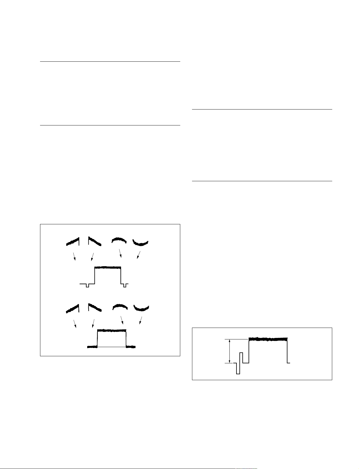
3-3-5. BLACK SHADING Adjustment
A
3-3-6. White Shading Adjustment
Preparation
. Setting for MSU-900
CLOSE button → ON (lit)
GAMMA OFF button → OFF (lit)
MASTER GAIN → 12
MASTER BLACK → 30
Adjustment Procedure
1. Adjustment Item:
MENU: SERVICE
PAGE: BLACK SHADING
ITEM: H SAW, H PARA, V SAW, V PARA [R],
[G], [B]
Specification:
Adjust so that each WFM channel becomes
as flat as possible.
(Check this in the mode of V: FIELD, H:
LINE.)
(H SAW) (H PARA)
(V SAW) (V PARA)
Equipment: Waveform monitor (R, G, B)
Test Point: SDI 1 connector (HDC1000/1500)
SDI connector (HDC1400/1550)
SDI 1 connector (HDCU1080)
Object: Full white pattern
Note
When performing the white shading adjustment, make sure
the following conditions are proper. If not, proper adjustment can not be obtained.
. White pattern is not uneven.
. Luminance is correctly adjusted.
. Iris and zoom control of the lens are correctly adjusted.
Preparations
. Setting for MSU-900
KNEE OFF button → OFF (lit)
. Shoot the fully occupied white area of the white pattern
on the underscanned monitor frame.
. Iris of the lens: A = 600 ± 20 mV (at F4 to F5.6)
(If the lens aperture is greater than F5.6, adjust the light
amounts with shutter.)
. Lens Focus: ∞
. Lens Extender/Shrinker: x2, x0.8 → OFF
. Set the setup menu as follows.
MENU: OPERATION
PAGE: LENS FILE
ITEM: FILE
(Select the file in accordance with the lens attached. If
there is no appropriate file, select NO OFFSET, then
change the name of lens with MSU.)
2. Execute file storing for each format.
MENU: SERVICE
PAGE: BLACK SHADING
ITEM: STORE FILE
HDC1000/V1(E)
3-11
Page 86
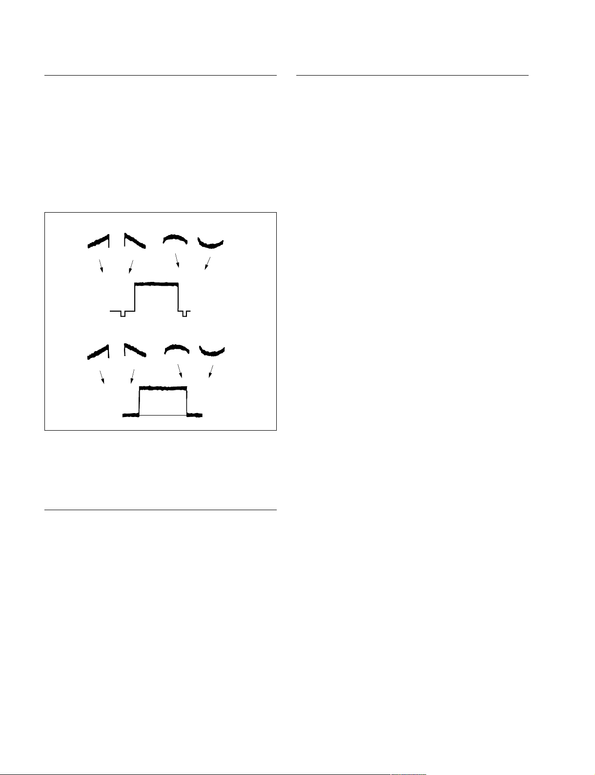
Adjustment Procedure
Adjustment for Lens Extender/Shrinker
1. Adjust the white balance.
WHITE button/MSU-900 → ON (lit)
2. If the shading is monitored, proceed as follows.
MSU menu operation:
. MAINTENANCE button → ON (lit)
. Touch panel operation
[Adjusting] → [White|Shading] → [R]
. Adjustment Items: H Saw, H Para, V Saw, V Para
(H SAW) (H PARA)
(V SAW) (V PARA)
3. Adjust for G-ch in the same manner.
4. Adjust for B-ch in the same manner.
5. Adjust the white balance.
WHITE button/MSU-900 → ON (lit)
OHB File Store
When the WHITE or shading of V is out of alignment by
using the lens extender or lens shrinker, perform the
following adjustment (lens adjustment) after the completion of OHB file store.
6. Adjust the white balance.
WHITE button/MSU-900 → ON (lit)
7. (In the status of lens: x1) Perform the lens file store.
MSU menu operation:
. FILE button → ON (lit)
. Touch panel operation
[Lens|File] → [Lens|Store] → [Store]
8. Lens extender (x2) → ON
or lens shrinker (x0.8) → ON
9. Adjust the white balance.
WHITE button/MSU-900 → ON (lit)
10. MSU menu operation:
. MAINTENANCE button → ON (lit)
. Touch panel operation
[Lens|Adjusting] → [V|Mod|Saw]
Adjustment Item: R, G, B
Specification: Set the V modulation correction
value as required.
11. Perform the lens file store.
MSU menu operation:
. FILE button → ON (lit)
. Touch panel operation
[Lens|File] → [Lens|Store] → [Store]
12. Lens extender (x2) → OFF
or lens shrinker (x0.8) → OFF
MSU menu operation:
. FILE button → ON (lit)
. Touch panel operation
[OHB|File] → [OHB|Store] → [Store]
3-12
HDC1000/V1(E)
Page 87
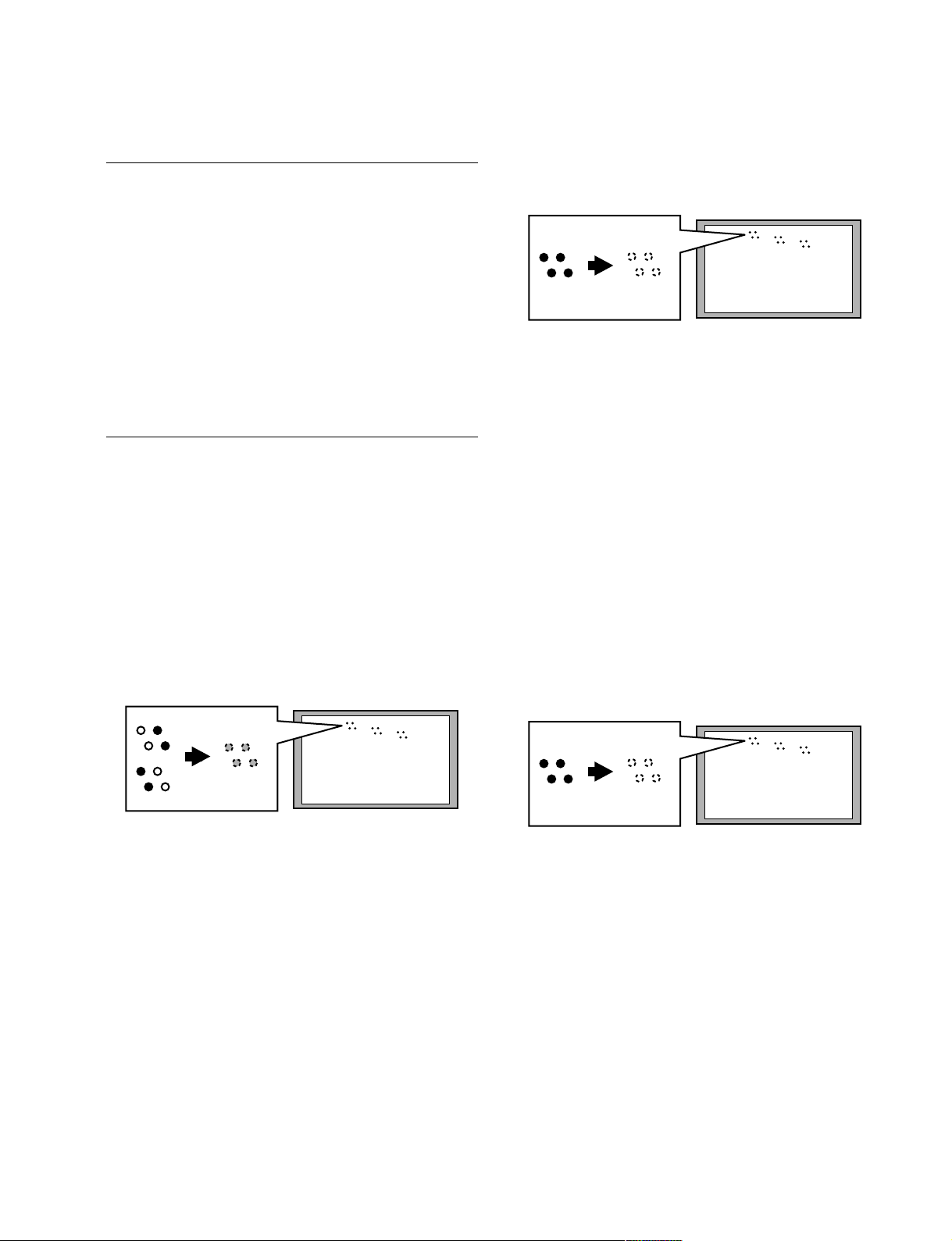
3-3-7. RPN Adjustment
Preparation
. Adjust the color monitor manually for better display
condition.
. Setting for MSU-900
CLOSE button → ON (lit)
DETAIL button → OFF (lit)
MASTER GAIN → 12
. Menu setting
MENU: SERVICE
PAGE: OHB_ADJ2
ITEM: CONC. TEST MODE → ON
Adjustment Procedure
Specification:
Adjust so that the dots displayed on the
color monitor (R/G/B: four dots each)
disappear.
4. Execute file storing.
MENU: SERVICE
PAGE: OHB_ADJ2
ITEM: STORE FILE
R
G
B
Color monitor
. 1080_59.94i/50i/29.97PsF/25PsF/23.98PsF
1. Adjustment Item:
MENU: SERVICE
PAGE: OHB_ADJ1
ITEM: DC_ADJ_B [R1], [G1], [B1]
Specification:
Adjust so that the dots displayed on the
color monitor (R/G/B: four dots each) are
of the same brightness.
R
G
B
Color monitor
2. Execute file storing.
MENU: SERVICE
PAGE: OHB_ADJ1
ITEM: STORE FILE
3. Adjustment item
MENU: SERVICE
PAGE: OHB_ADJ2
ITEM: DC_ADJ_C [R1], [G1], [B1]
. 1080_59.94P/50P
1. Adjustment Item:
MENU: SERVICE
PAGE: OHB_ADJ2
ITEM: SH_ADJ_A [R1], [G1], [B1]
SH_ADJ_A [R2], [G2], [B2]
Specification:
Adjust so that the dots displayed on the
color monitor (R/G/B: four dots each)
disappear.
R
G
B
Color monitor
The left 2 out of 4: SH_ADJ_A [R1], [G1], [B1]
The right 2 out of 4: SH_ADJ_A [R2], [G2], [B2]
2. Execute file storing.
MENU: SERVICE
PAGE: OHB_ADJ2
ITEM: STORE FILE
n
If the residual point noise (RPN) still remains after the
RPN adjustment, perform the RPN compensation (Section
3-10). However, this function is available for Software
Version 1.11 and higher.
HDC1000/V1(E)
3-13
Page 88
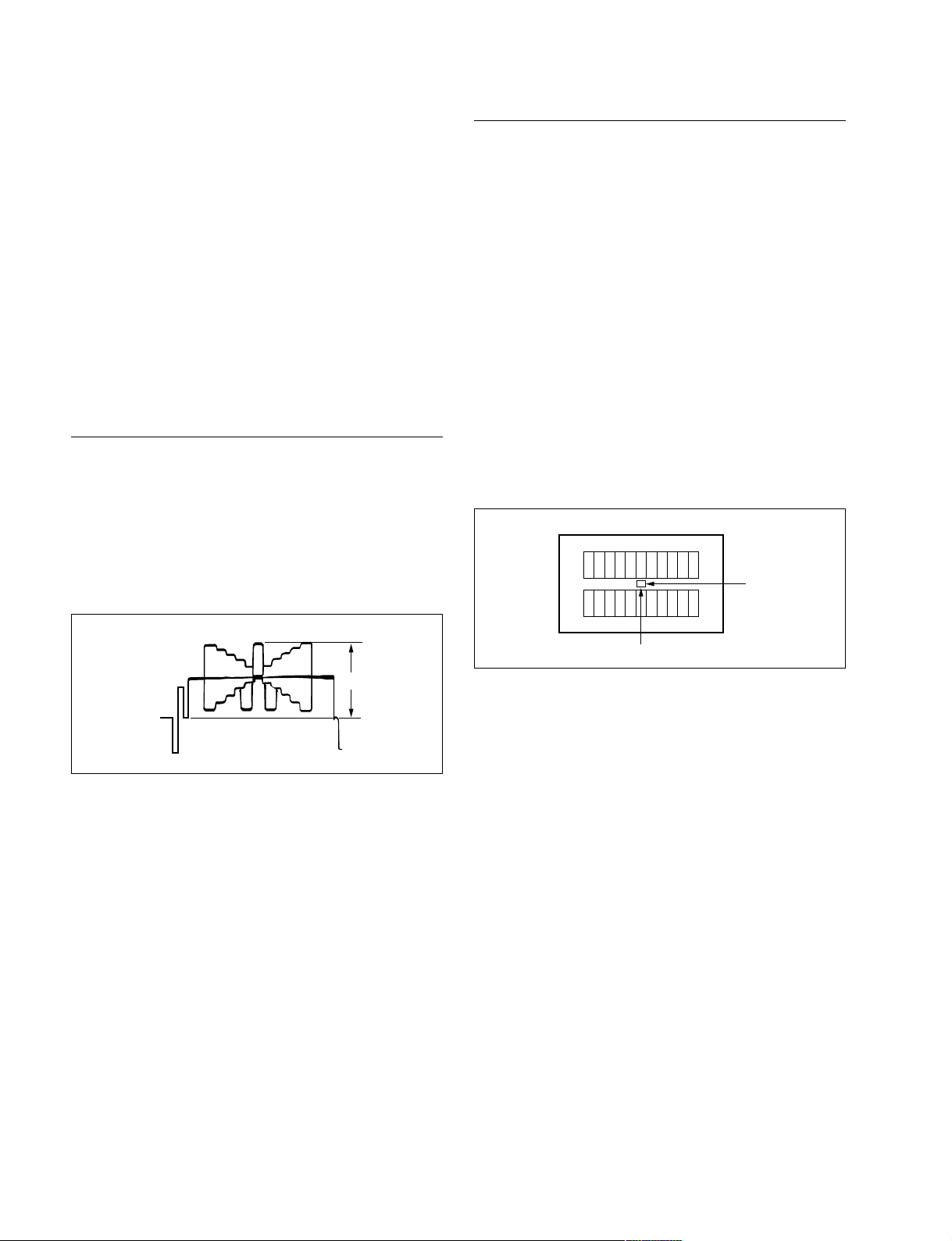
3-4. Video System Level Adjustment
Adjustment Procedure
n
Perform the video system level adjustment at the request of
the customer.
3-4-1. H/V Ratio Adjustment
Equipment: Waveform monitor (R, G, B)
Test Point: SDI 1 connector (HDC1000/1500)
SDI connector (HDC1400/1550)
SDI 1 connector (HDCU1080)
Object: Grayscale chart
Preparations
. Setting for MSU-900
DETAIL OFF button → ON (dark)
KNEE OFF button → OFF (lit)
. Shoot the grayscale chart so that the chart frame is
aligned with the underscanned monitor frame.
. Iris of the lens: A = 600 ± 20 mV
1. MSU menu operation:
. PAINT button → ON (lit)
. Touch panel operation
(Page 1/3) → [Detail] → [Detail|1]
. Set each item as follows.
Level → 99
Limiter → 0
Crispening → _25
Level Dep → 25
2. MSU menu operation:
. Touch panel operation
[Detail|2]
Adjustment Item: H/V Ratio
Specification: A ratio between H and V detail
amounts (white) to be added shall
be equal. (from 20 to 40)
H
V
A
3-14
HDC1000/V1(E)
Page 89
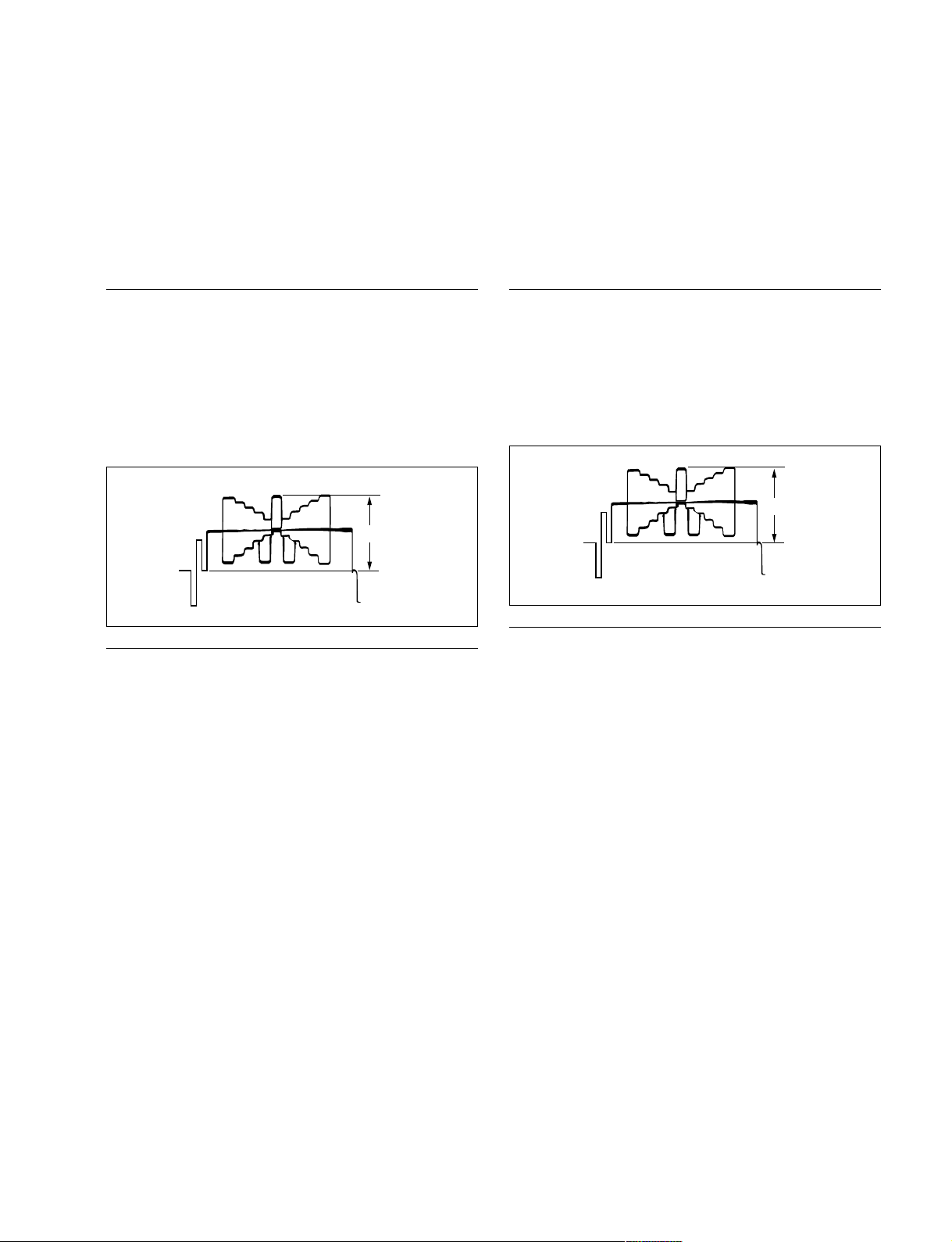
3-4-2. Detail Level Adjustment
3-4-3. Crispening Adjustment
Equipment: Waveform monitor (R, G, B)
Test Point: SDI 1 connector (HDC1000/1500)
SDI connector (HDC1400/1550)
SDI 1 connector (HDCU1080)
Object: Grayscale chart
Preparations
. Setting for MSU-900
DETAIL OFF button → ON (dark)
KNEE OFF button → OFF (lit)
. Shoot the grayscale chart so that the chart frame is
aligned with the underscanned monitor frame.
. Iris of the lens: A = 600 ± 20 mV
A
Equipment: Waveform monitor (R, G, B)
Test Point: SDI 1 connector (HDC1000/1500)
SDI connector (HDC1400/1550)
SDI 1 connector (HDCU1080)
Object: Grayscale chart
Preparations
. Setting for MSU-900
DETAIL OFF button → ON (dark)
. Shoot the grayscale chart so that the chart frame is
aligned with the underscanned monitor frame.
. Iris of the lens: A = 600 ± 20 mV
A
Adjustment Procedure
MSU menu operation:
. PAINT button → ON (lit)
. Touch panel operation
(Page 1/3) → [Detail] → [Detail|1]
Adjustment Item: Level
Specification: Adjust the detail level to be added to
each step of the grayscale for the
desired level.
Adjustment Procedure
1. Adjust the white balance.
WHITE button/MSU-900 → ON (lit)
2. Adjust the crispening level.
MSU menu operation:
. PAINT button → ON (lit)
. Touch panel operation
(Page 1/3) → [Detail] → [Detail|1]
Adjustment Item: Crispening
Specification: Set Crispening to _99 once, and
turn slowly for increment until the
noise at the black level of the
waveform just decreases, or until an
appropriate crispening level is
obtained.
HDC1000/V1(E)
3-15
Page 90
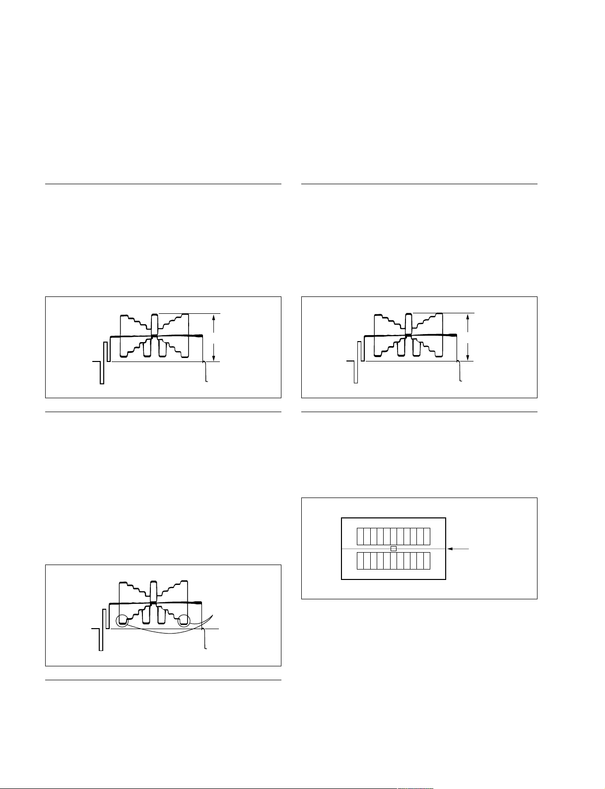
3-4-4. Level Dependent Adjustment
3-4-5. Detail Clip Adjustment
Equipment: Waveform monitor (R, G, B)
Test Point: SDI 1 connector (HDC1000/1500)
SDI connector (HDC1400/1550)
SDI 1 connector (HDCU1080)
Object: Grayscale chart
Preparations
. Setting for MSU-900
DETAIL OFF button → ON (dark)
LEVEL DEP OFF button → ON (dark)
. Shoot the grayscale chart so that the chart frame is
aligned with the underscanned monitor frame.
. Iris of the lens: A = 600 ± 20 mV
A
Equipment: Waveform monitor (R, G, B)
Test Point: SDI 1 connector (HDC1000/1500)
SDI connector (HDC1400/1550)
SDI 1 connector (HDCU1080)
Object: Grayscale chart
Preparations
. Setting for MSU-900
KNEE OFF button → OFF (lit)
DETAIL OFF button → ON (dark)
. Shoot the grayscale chart so that the chart frame is
aligned with the underscanned monitor frame.
. Iris of the lens: A = 600 ± 20 mV
A
Adjustment Procedure
MSU menu operation:
. PAINT button → ON (lit)
. Touch panel operation
(Page 1/3) → [Detail] → [Detail|1]
Adjustment Item: Level Dep
Specification: Set Level Dep to _99 once. And turn
slowly for increment until spikes at
portions B just decrease. Or adjust for
the desired level.
B
Note
Adjustment Procedure
1. Adjust the white balance.
WHITE button/MSU-900 → ON (lit)
2. Make a line selection at the center white portion of the
grayscale chart.
Line select
After adjustment is completed, be sure to perform Section
3-4-1 “H/V Ratio Adjustment”.
3-16
HDC1000/V1(E)
Page 91
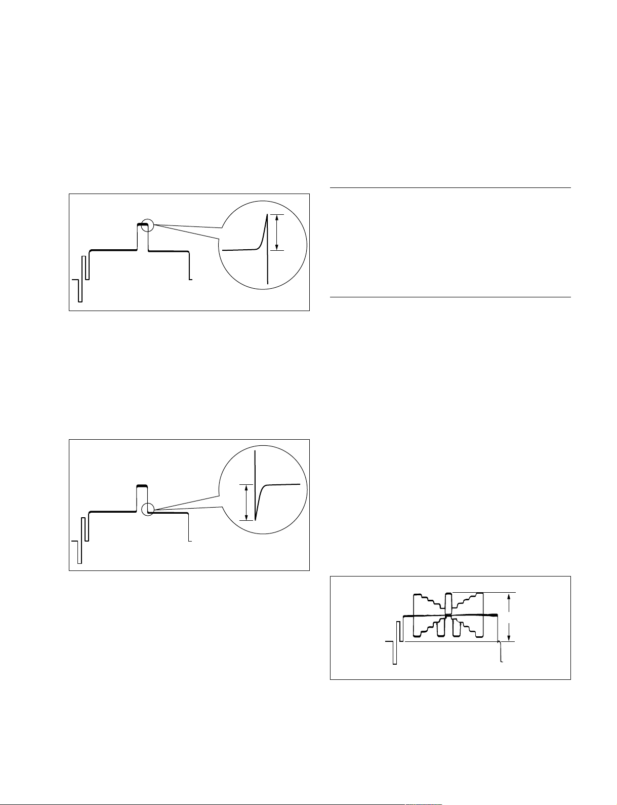
3. Adjust the white limiter.
MSU menu operation:
. PAINT button → ON (lit)
. Touch panel operation
(Page 1/3) → [Detail] → [Detail|3]
Adjustment Item: W.Limiter
Specification: Adjust the edge at portion B for the
desired clip level.
3-4-6. Auto-iris Adjustment
Equipment: Waveform monitor (R, G, B)
Test Point: SDI 1 connector (HDC1000/1500)
SDI connector (HDC1400/1550)
SDI 1 connector (HDCU1080)
Object: Grayscale chart
Preparations
. Setting for MSU-900
B
AUTO button (Iris control block) → ON (lit)
KNEE OFF button → OFF (lit)
. Shoot the grayscale chart so that the chart frame is
aligned with the underscanned monitor frame.
Adjustment Procedure
4. Adjust the black limiter.
MSU menu operation:
. PAINT button → ON (lit)
. Touch panel operation
(Page 1/3) → [Detail] → [Detail|3]
Adjustment Item: B.Limiter
Specification: Adjust the edge at portion C for the
desired clip level.
C
1. Adjust the white balance.
WHITE button/MSU-900 → ON (lit)
2. Adjust APL ratio.
MSU menu operation:
. MAINTENANCE button → ON (lit)
. Touch panel operation
[Lens|Adjusting] → [Auto|Iris]
Adjustment Item: APL Ratio
Specification: Set the auto-iris operation mode as
required. (It can be set between the
average and the peak value of video
signal.)
99 → average
_99 → peak value
3. Adjust the auto-iris level.
MSU menu operation:
Adjustment Item: Level
Specification: A = 700 ± 7 mV
A
HDC1000/V1(E)
3-17
Page 92
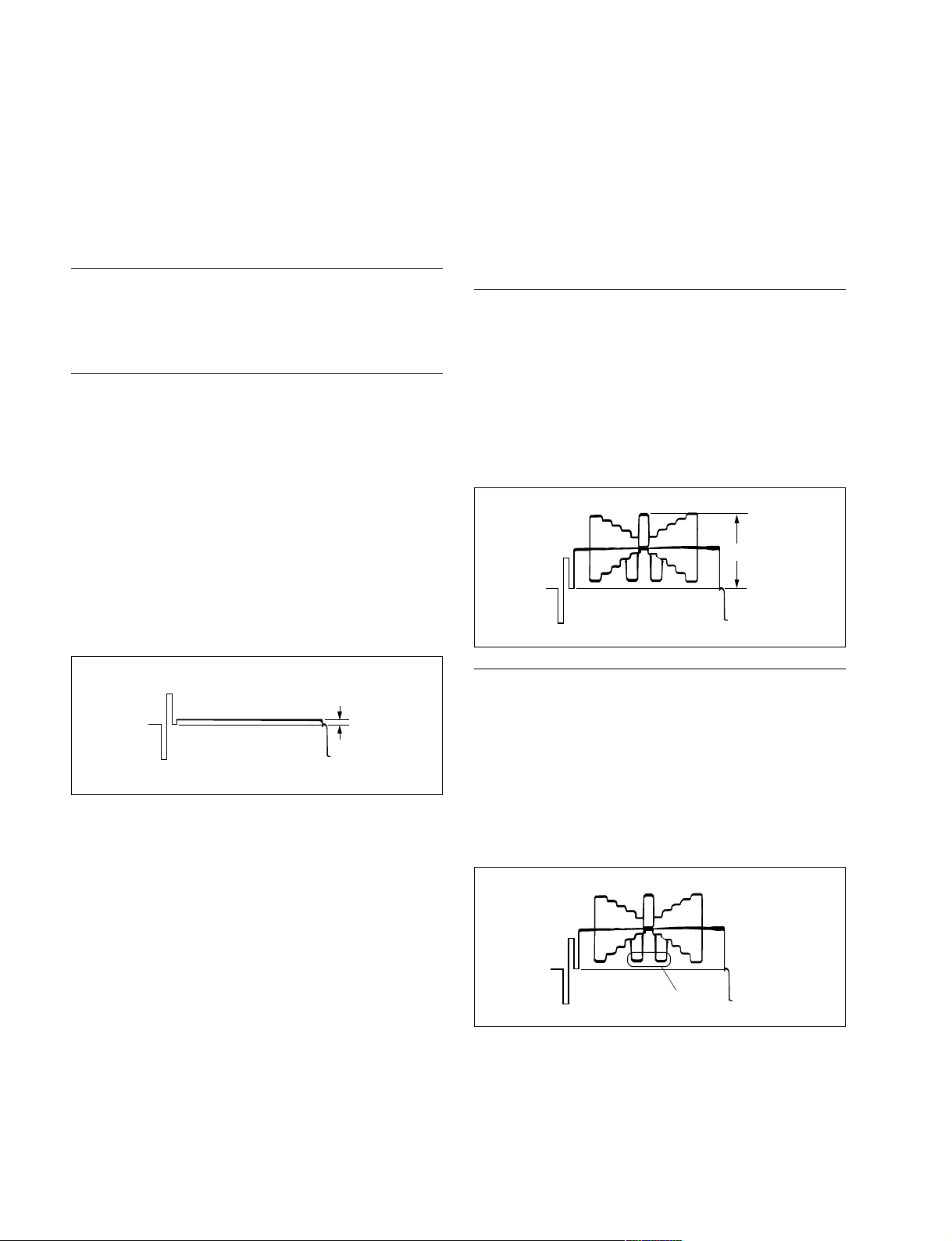
3-4-7. Pedestal Level Adjustment
3-4-8. Flare Adjustment
Equipment: Waveform monitor (R, G, B)
Test Point: SDI 1 connector (HDC1000/1500)
SDI connector (HDC1400/1550)
SDI 1 connector (HDCU1080)
Preparations
. Settings for MSU-900
CLOSE button → ON (lit)
Adjustment Procedure
1. MSU menu operation:
. PAINT button → ON (lit)
. Touch panel operation
(Page 1/3) → [Black]
Adjustment Item: R, G, B Master
Specification: Adjust the levels A for preferred
level for R, G and B respectively.
To adjust all levels for R, G and B
simultaneously, adjust them using
the Master.
(Reference value: A = 21 mV)
Equipment: Waveform monitor (R, G, B)
Test Point: SDI 1 connector (HDC1000/1500)
SDI connector (HDC1400/1550)
SDI 1 connector (HDCU1080)
Object: Grayscale chart
Preparations
. Setting for MSU-900
KNEE OFF button → OFF (lit)
DETAIL OFF button → OFF (lit)
MATRIX OFF button → OFF (lit)
. Shoot the grayscale chart so that the chart frame is
aligned with the underscanned monitor frame.
. Iris of the lens: A = 600 ± 20 mV
A
Adjustment Procedure
A
1. MSU menu operation:
. PAINT button → ON (lit)
. Touch panel operation
(Page 1/3) → [Flare]
Adjustment Item: R, G, B
Specification: Adjust the levels B for preferred
level for R, G and B respectively.
B
3-18
HDC1000/V1(E)
Page 93
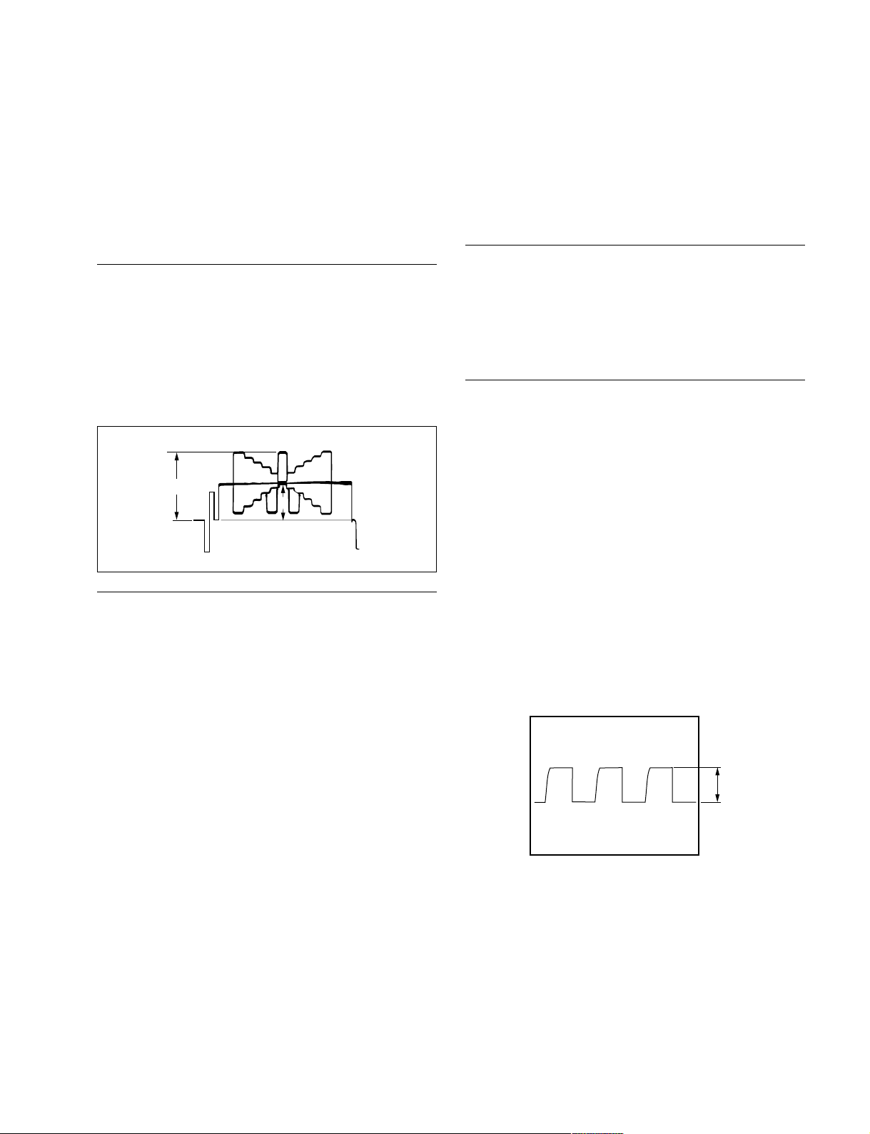
3-4-9. Gamma Correction Adjustment
3-4-10. Knee Point/Knee Slope Adjustment
Equipment: Waveform monitor (R, G, B)
Test Point: SDI 1 connector (HDC1000/1500)
SDI connector (HDC1400/1550)
SDI 1 connector (HDCU1080)
Object: Grayscale chart
Preparations
. Setting for MSU-900
KNEE OFF button → OFF (lit)
GAMMA OFF button → ON (dark)
. Shoot the grayscale chart so that the chart frame is
aligned with the underscanned monitor frame.
. Iris of the lens: A = 700 ± 20 mV
A
B
Adjustment Procedure
1. Adjust the white balance.
WHITE button/MSU-900 → ON (lit)
2. MSU menu operation:
. PAINT button → ON (lit)
. Touch panel operation
(Page 2/3) → [Gamma]
Adjustment Item: R, G, B, Master
Specification: Adjust the cross points B of the
grayscale for preferred level for R,
G and B respectively.
To adjust all cross points for R, G
and B simultaneously, adjust them
using the Master.
Equipment: Waveform monitor (R, G, B)
Test Point: SDI 1 connector (HDC1000/1500)
SDI connector (HDC1400/1550)
SDI 1 connector (HDCU1080)
Preparations
. Setting for MSU-900
MASTER GAIN → +6 dB
TEST1 button → ON (lit)
KNEE OFF button → ON (dark)
Adjustment Procedure
1. MSU menu operation:
. PAINT button → ON (lit)
. Touch panel operation
(Page 2/3) → [Knee|Slope]
. Set Master to +99.
2. MSU menu operation:
. Touch panel operation
(Page 2/3) → [Knee|Point]
Adjustment Item: R, G, B Master
Specification: Adjust the levels A for preferred
level for R, G and B respectively.
To adjust all levels for R, G and B
simultaneously, adjust them using
the Master.
(Reference value: A = 686 mV)
A
HDC1000/V1(E)
3-19
Page 94
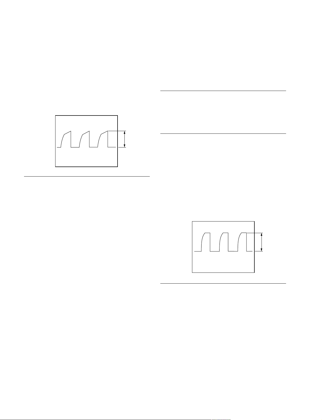
3. MSU menu operation:
. Touch panel operation
(Page 2/3) → [Knee|Slope]
Adjustment Item: R, G, B Master
Specification: Adjust the levels B for preferred
level for R, G and B respectively.
To adjust all levels for R, G and B
simultaneously, adjust them using
the Master.
(Reference value: B = 735 mV)
3-4-11. White Clip Level Adjustment
Equipment: Waveform monitor (R, G, B)
Test Point: SDI 1 connector (HDC1000/1500)
SDI connector (HDC1400/1550)
SDI 1 connector (HDCU1080)
Preparations
. Setting for MSU-900
MASTER GAIN → +12 dB
TEST1 button → ON (lit)
Setting after Adjustment
. MASTER GAIN/MSU-900 → 0 dB
. KNEE OFF button/MSU-900 → OFF (lit)
B
Adjustment Procedure
1. MSU menu operation:
. PAINT button → ON (lit)
. Touch panel operation
(Page 2/3) → [White|Clip]
Adjustment Item: Adjust the levels A for preferred
level for R, G and B respectively.
To adjust all levels for R, G and B
simultaneously, adjust them using
the Master.
(Reference value: A = 756 mV)
A
Setting after Adjustment
3-20
. MASTER GAIN/MSU-900 → 0 dB
. TEST1 button/MSU-900 → OFF (dark)
HDC1000/V1(E)
Page 95

3-4-12. File Store
After adjustments described in Section 3-4 are completed,
be sure to execute the reference file store.
1. MSU menu operation:
. FILE button → ON (lit)
. Touch panel operation
[Reference] → [Ref|Store] → [Start]
2. When the store operation is completed, the message
“Completed” is displayed.
HDC1000/V1(E)
3-21
Page 96
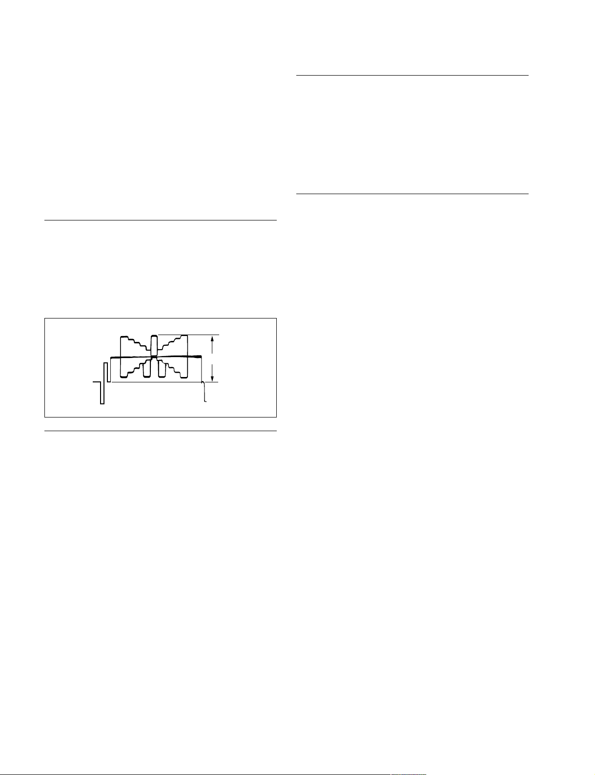
3-5. ND Offset Adjustment
OHB File Store
When the filter disk unit is replaced alone, the correction
of white balance is required. Proceed as follows.
Equipment: Waveform monitor (R, G, B)
Test Point: SDI 1 connector (HDC1000/1500)
SDI connector (HDC1400/1550)
SDI 1 connector (HDCU1080)
Object: Grayscale chart
Preparations
. Shoot the grayscale chart so that the chart frame is
aligned with the underscanned monitor frame.
. Setting for MSU-900
AUTO button (Iris control block) → ON (lit)
. Iris of the lens: A = 600 ±20 mV
A
1. MSU menu operation:
. FILE button → ON (lit)
. Touch panel operation
[OHB|File] → [OHB|Store] → [Store]
2. When the store operation is completed, the message
“OHB File Stored” is displayed.
Setting after Adjustment
. MASTER GAIN/MSU-900 → 0 dB
Adjustment Procedure
1. FILTER CTRL button/MSU-900 → ON (lit)
2. Select the ND 1 filter.
ND 1 button/MSU-900 → ON (lit)
3. Adjust the white balance.
WHITE button/MSU-900 → ON (lit)
4. After the white balance adjustment is completed,
switch the filter from ND2 to ND5, and adjust the
white balance for each.
Set the GAIN for each ND filter as follows.
MASTER GAIN/MSU-900
. ND filter 2: 0 dB
. ND filter 3: 0 dB
. ND filter 4: 6 dB
. ND filter 5: 12 dB
3-22
HDC1000/V1(E)
Page 97
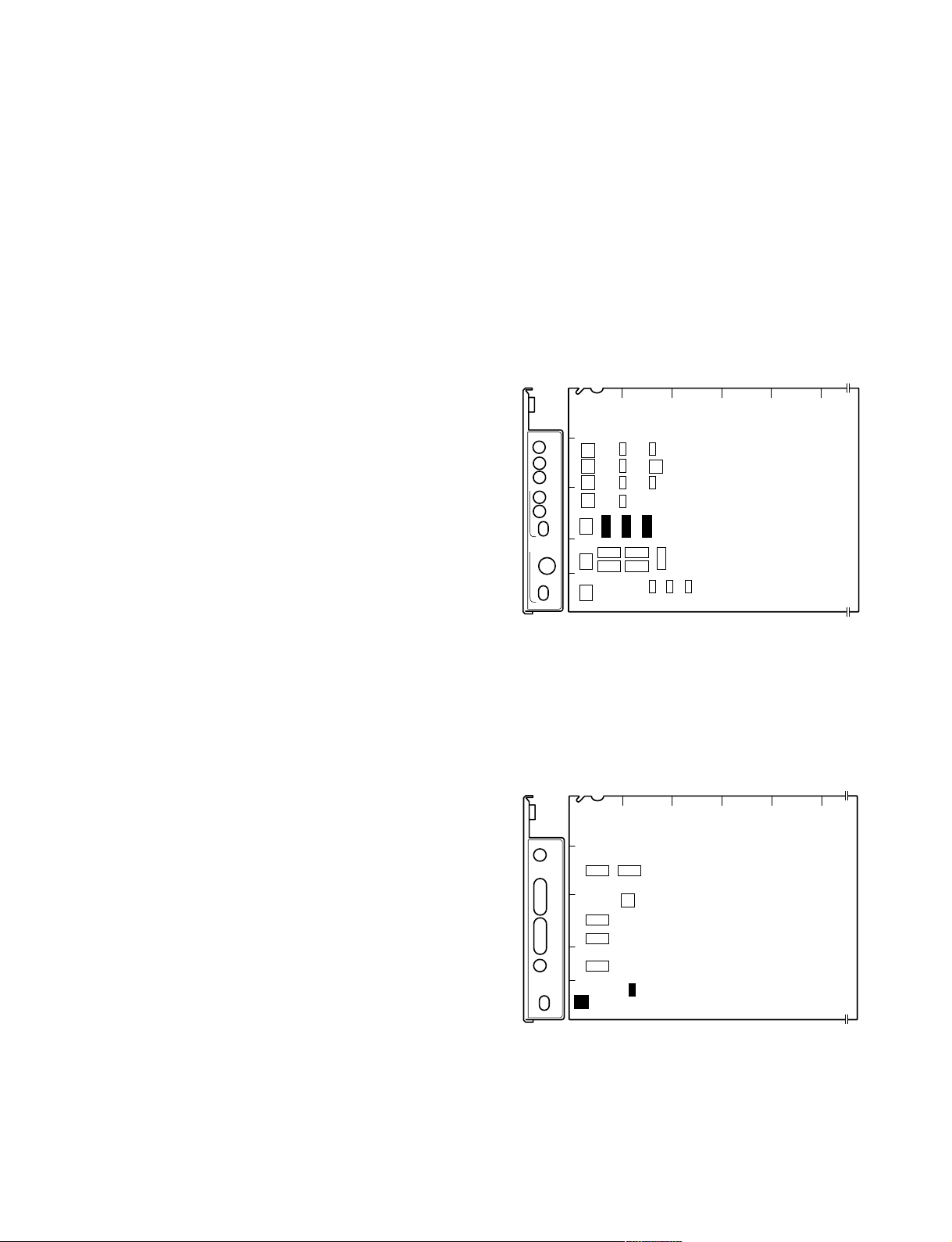
3-6. Adjustment Preparation of HDC1550
3-6-2. Precautions on Adjustments
3-6-1. Equipment Required
Measuring equipment
. Oscilloscope: Tektronix 2465B or equivalent
. Spectrum analyzer: Advantest R3131A or equivalent
. Signal generator: Tektronix TSG130A or equivalent
. Waveform monitor: Tectronix WFM700 or equivalent
Related equipment
. HD camera control unit HDCU-950
. HD TRIAX camera adapter HDFX100
Tools
. TRIAX cable: Fujikura cable (100 m, ø: 8.5 mm) or
(100 m) equivalent
. TRIAX cable: Fujikura cable (50 m, ø: 8.5 mm) or
equivalent
. TRIAX cable: Fujikura cable (300 m, ø: 8.5 mm) or
equivalent
m
. The 50 m and 300 m TRIAX cables are used for “3-8-3.
Return Frequency Adjustment” only.
. Unless otherwise specified, use the 100 m TRIAX cable
for adjustments.
. Confirm that all measuring equipment and related
equipment have been calibrated.
. Unless otherwise specified, use the 100 m TRIAX cable
for adjustments.
. Set the switches S418 to S420 for electrical adjustments
on the AT-149 board in HDCU-950 as follows, and also
set the system format to 1080/59.94i.
S418/AT-149 board: 60V
S419/AT-149 board: INTR
S420/AT-149 board: 1.001
AB C D E
1
AT
POWER
/1.001
90H
REFERENCE
REF IN
UN
LOCK
H PHASE
STEP
COARSE
DELAY
S404
S403
2
S406
S407
3
S427
HD
REM
BB
ADV
S405
4
S428
5
S423
S422
S419
S409
S410
S416
S417
S424
S421
S418
S408
S402
S412
S420
S411
S414
S413
S202
AT-149 board in HDCU-950 (Side A)
. Check that the switches S601 and S605 for electrical
adjustments on the DTX-1 board in HDCU-950 as
follows.
S601/DTX-1 board: SDI
S605/DTX-1 board: HD
HDC1000/V1(E)
DTX
POWER
OPTICAL
CONDITION
CCU
CHU
CHU
LOCK
RETURN SET
AB C D E
1
S607 S608
2
S610
S606
3
S603
4
S604
5
HD
REM
S605
SD
S601
DTX-1 board in HDCU-950 (Side A)
3-23
Page 98
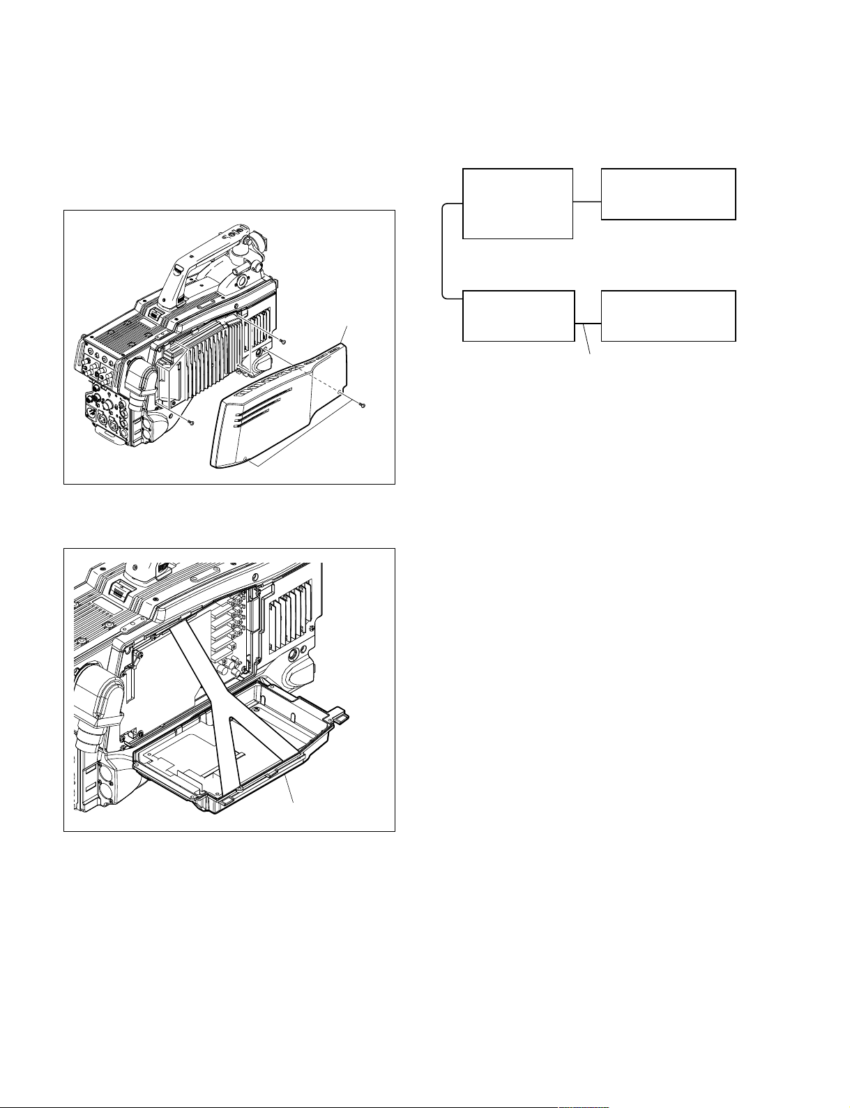
3-6-3. Connection
1. Remove the two screws to detach the outside pad sub
assembly.
2. Remove the five screws.
4. Connect the equipments as shown in the following
figure.
HDCU-950
CAMERA
Optical fiber cable
RET1
Signal generator
Outside pad
assembly
B2.6 x 8
B2.6 x 8
B2.6 x 8
3. Open the heat sink sub assembly as shown in the
following figure.
HDCU
HDFX100
CAMERA/
HDTX
HDC1550
HDCU/
HDFX
TRIAX cable
3-24
Heat sink sub assembly
HDC1000/V1(E)
Page 99
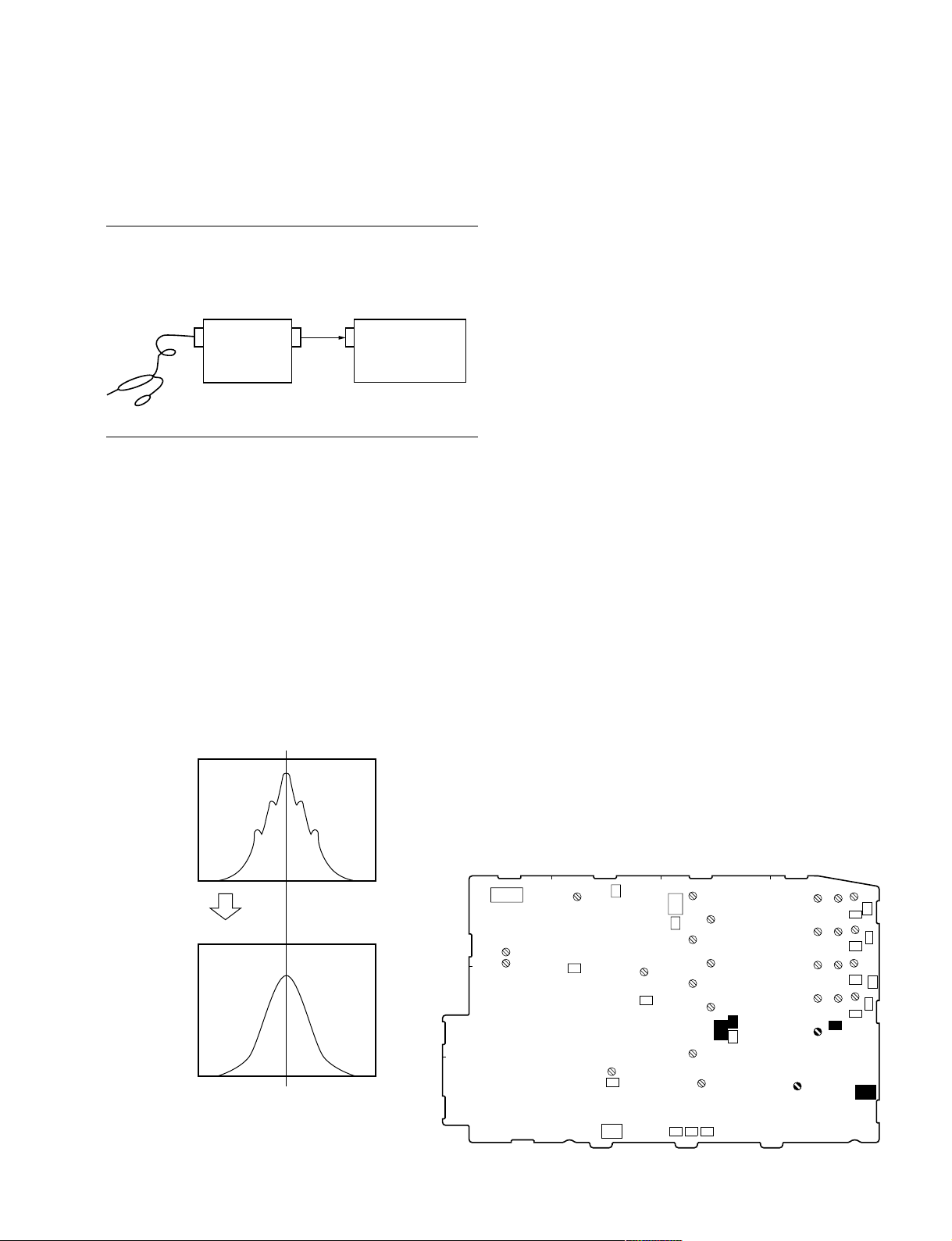
3-7. TONE Adjustment (HDC1550)
3-7-2. CCU DATA Demodulation Adjustment
3-7-1. CHU DATA/TONE Frequency
Adjustment
Preparation
1. Connect the oscilloscope to the spectrum analyzer as
shown below.
Probe
OUT
Oscilloscope Spectrum analyzer
Adjustment procedure
2. Adjust the frequency at the waveform peak while
changing the SPAN of the spectrum analyzer as
1 MHz → 50 kHz → 20 kHz.
Measuring equipment:
Spectrum analyzer
(via oscilloscope)
CENTER: 5.6 MHz
SPAN: 1 MHz → 50 kHz → 20 kHz
RBW: 300 Hz
Test point: TP106 (GND: E200)/TR-136 board
Adjusting point: 1LV101/TR-136 board
Specification: A = 5.600 ± 0.005 MHz
CH2INCH2
IN
Measuring equipment: Oscilloscope
Input mode: DC
Test point: TP202 (GND: E4)/TR-136 board
Adjusting point: 1LV202/TR-136 board
Specification: 0 ±40 mV
HDC1000/V1(E)
SPAN: 1 MHz
SPAN: 20 kHz
A
S1
1
RV601
RV602
2
A
3
RV761
TP801
B
TP605
RV721
TP721
E1
E2
TP604
RV801
TP401
TP603
E200
LV104
RV104
TP602
LV102
LV103
LV105
C
RV102
RV103
RV105
TP601
TP106
TP201
D
LV209
LV207
LV203
LV205
LV202
LV101
LV210
TP209
LV208
TP207
LV204
TP203
LV206
TP202
RV204
TP210
RV203
TP208
RV201
TP204
RV202
TP206
TP205
E4
TR-136 BOARD (SIDE A)
3-25
Page 100
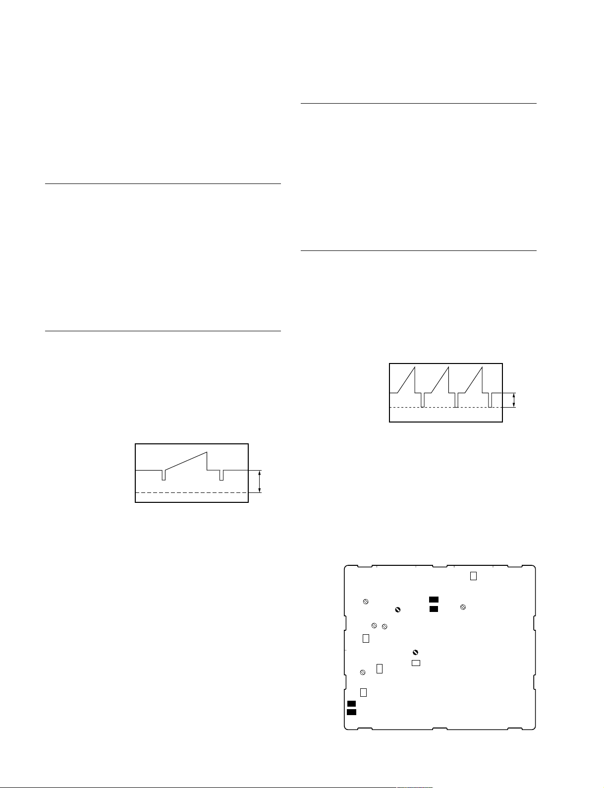
3-8. Video System Adjustment (HDC1550)
3-8-2. Return Sync Level Adjustment
n
Be sure to perform “3-7. TONE Adjustment” before
adjusting the video system.
3-8-1. Demodulation Tuning Adjustment
Preparation
1. Set S601 and S605 for adjustment on the DTX-1 board
in HDCU-950 as follows. (Refer to Section 3-6-2.)
S601: VBS
S605: SD
2. . Connect the signal generator to the RET 1 IN
connector on HDCU-950, and input the MOD
RAMP signal.
. Set S1 on the DM-141 board in HDFX100 to “0”.
Adjustment procedure
3. Measuring equipment:
Oscilloscope
Input mode: DC
Test point: TP201 (GND: E1)/MX-109 board
Adjusting point: 1LV201/MX-109 board
Specification: A = 3.4 ± 0.1 V dc
A
GND
4. . Re-set S1 on the DM-141 board in HDFX100 to
“F”.
. Set S601 and S605 on the DTX-1 board in HDCU-
950 as follows. (Refer to Section 3-6-2.)
S601: SDI
S605: HD
5. Disconnect the signal generator from the RET 1 IN
connector on HDCU-950.
Preparation
1. Set S601 and S605 for adjustment on the DTX-1 board
in HDCU-950 as follows. (Refer to Section 3-6-2.)
S601: VBS
S605: SD
2. . Connect the signal generator to the RET 1 IN
connector on HDCU-950, and input the MOD
RAMP signal.
. Set S1 on the DM-141 board in HDFX100 to “0”.
Adjustment procedure
3. Measuring equipment:
Oscilloscope
Input mode: DC
Test point: TP202 (GND: E4)/MX-109 board
Adjusting point: 1RV201/MX-109 board
Specification: A = 600 mV
A
4. . Re-set S1 on the DM-141 board in HDFX100 to
“F”.
. Set S601 and S605 on the DTX-1 board in HDCU-
950 as follows. (Refer to Section 3-6-2.)
S601: SDI
S605: HD
5. Disconnect the signal generator from the RET 1 IN
connector on HDCU-950.
D
TP101
LV101
E
1
A
LV301
TP301
RV302
RV301
E3
B
LV201
LV302
C
E1
TP201
RV201
TP203
3-26
2
TP302
TP202
E4
MX-109 BOARD (SIDE A)
HDC1000/V1(E)
 Loading...