

Sony HCD-XB33K, HCD-XB44K Service Manual

HCD-XB33K/XB44K
MICROFILM
SERVICE MANUAL
Photo: HCD-XB44K
*Dolby noise reduction manufactured under license
from Dolby Laboratories Licensing Corporation.
“DOLBY” and the double-D symbol a are
trademarks of the Dolby Laboratories Licensing
Corporation.
CD
Section
Tape Deck
Section
E Model
Model Name Using Similar Mechanism HCD-D290/
G3300/XB3
CD Mechanism Type CDM37L-5BD29AL
Base Unit Name BU-5BD29AL
Optical Pick-up Name KSS-213D/Q-NP
Model Name Using Similar Mechanism HCD-D290/
G3300/XB3
Tape Transport Mechanism Type TCM-220WR2
SPECIFICATIONS
AUDIO POWER SPECIFICATIONS
POWER OUTPUT AND TOTAL HARMONIC DISTORTION:
With 8 ohm loads, both channels driven, from 70-20,000 Hz; rated 100
watts per channel minimum RMS power, with no more than 0.9 % total
harmonic distortion from 250 milliwatts to rated output.
Amplifier section
(HCD-XB33K)
The following measured at AC 120/240 V, 50 Hz
DIN power output (Rated):
100 + 100 watts (6 ohms at 1 kHz, DIN)
Continuous RMS power output (Reference):
120 + 120 watts
(6 ohms at 1 kHz, 10% THD)
Peak music power potput (Reference):
1,500 watts
(HCD-XB44K)
The following measured at AC 120/240 V, 50 Hz
DIN power output (Rated):
120 + 120 watts (6 ohms at 1 kHz, DIN)
Continuous RMS power output (Reference):
140 + 140 watts
(6 ohms at 1 kHz, 10% THD)
Peak music power output (Reference):
2,000 watts
Inputs
PHONO IN (phono jacks):
sensitivity 3 mV, impedance 47 kilohms
MIX MIC (phone jack): sensitivity 1 mV, impedance 10 kilohms
VIDEO/MD (AUDIO) IN (phono jacks):
sensitivity 250 mV, impedance 47 kilohms
Outputs
PHONES (stereo phone jack):
accepts headphones of 8 ohms or more
VIDEO/MD (AUDIO) OUT (phono jacks):
voltage 250 mV, impedance 1 kilohm
SPEAKER: impedance of 6 to 16 ohms
SURROUND SPEAKER:accepts impedance of 16 ohms
(HCD-XB33K)
— Continued on next page —
COMPACT DISC DECK RECEIVER

CD player section
System Compact disc and digital audio system
Laser Semiconductor laser (λ = 780nm).
Emission
duration: continuous
Laser output Max. 44.6µW*
*This output is the value measured at a distance
of 200 mm from the objective lens surface on
the Optical Pick-up Block with 7 mm aperture.
Wavelength 780 – 790 nm
Frequency response 2 Hz – 20 kHz (±0.5 dB)
Signal-to-noise ratio More than 90 dB
Dynamic range More than 90 dB
CD DIGITAL OUT
(square optical connector jack, rear panel)
Wave length: 600 nm
Output level: – 18 dBm
Tape player section
Recording system 4-track 2-channel stereo
Frequency response (DOLBY NR OFF)
60 – 13,000 Hz (±3 dB), using a Sony
TYPE I cassette
60 – 14,000 Hz (±3 dB), using a Sony
TYPE II cassette
Tuner section
FM stereo, FM/AM superheterodyne tuner
FM tuner section
Tuning range
(2 band model)
Antenna FM wire antenna
Antenna terminals 75 ohm unbalanced
Intermediate frequency 10.7 MHz
AM tuner section
Tuning range 531 – 1,602 kHz
(with the tuning interval set at 9 kHz)
530 – 1,710 KHz
(with the tuning interval set at 10 kHz)
CAUTION
Use of controls or adjustments or performance of procedures
other than those specified herein may result in hazardous radiation
exposure.
Notes on chip component replacement
• Never reuse a disconnected chip component.
• Notice that the minus side of a tantalum capacitor may be
damaged by heat.
Flexible Circuit Board Repairing
• Keep the temperature of soldering iron around 270˚C
during repairing.
• Do not touch the soldering iron on the same conductor of the
circuit board (within 3 times).
• Be careful not to apply force on the conductor when soldering
or unsoldering.
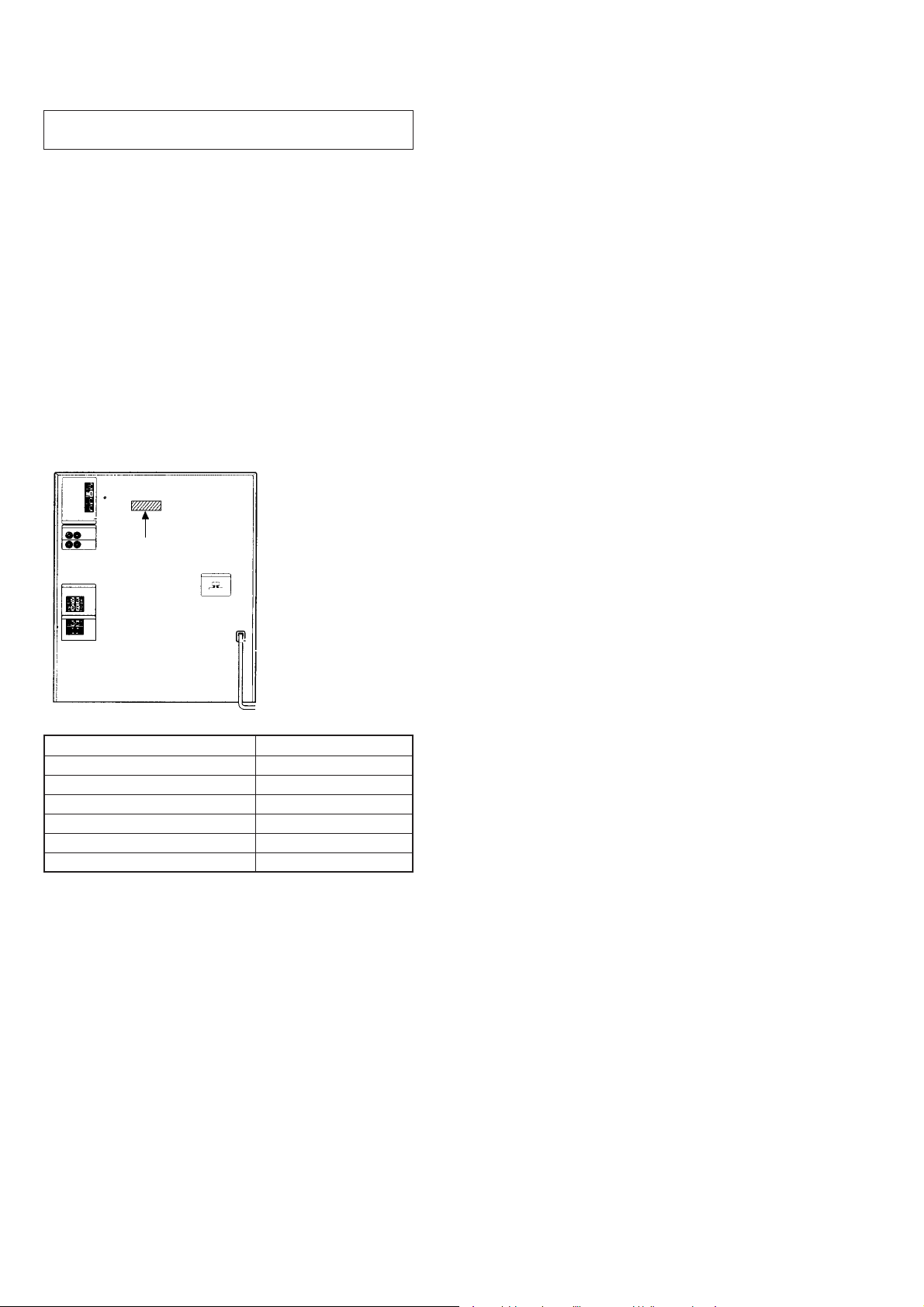
Laser component in this product is capable
of emitting radiation exceeding the limit for
Class 1.
This appliance is classified as a CLASS 1 LASER product. The
CLASS 1 LASER PRODUCT MARKING is located on the rear
exterior.
The following caution label is located inside the unit.
Antenna AM loop antenna, External antenna terminals
Intermediate frequency 450 kHz
General
Power requirements
Other models: 110 – 120 V or 220 – 240 V
Power consumption
(HCD-XB33K): 240 watts
(HCD-XB44K): 250 watts
Dimensions (w/h/d) Approx. 355 x 425 x 435 mm (14 x 16 3/4 x 17
Mass Approx. 14.0 kg (30 lb 14 oz.)
Supplied accessories: AM loop antenna (1)
Design and specifications are subject to change without notice.
AC, 50/60 Hz Adjustable with voltage selector
1
/4 in) incl. projecting parts and controls
Remote RM-SD70S (1)
Size AA (R6) batteries (2)
FM wire antenna (1)
Speaker cords* (HCD-XB44K) (2)
SAFETY-RELATED COMPONENT WARNING!!
COMPONENTS IDENTIFIED BY MARK ! OR DO TTED LINE WITH
MARK ! ON THE SCHEMATIC DIAGRAMS AND IN THE PARTS
LIST ARE CRITICAL TO SAFE OPERATION. REPLACE THESE
COMPONENTS WITH SONY PARTS WHOSE PART NUMBERS
APPEAR AS SHOWN IN THIS MANUAL OR IN SUPPLEMENTS
PUBLISHED BY SONY.
— 2 —

TABLE OF CONTENTS
1. GENERAL
– FRONT PANEL – ···························································· 5
– BACK PANEL – ······························································ 6
2. DISASSEMBLY ·····························································10
3. TEST MODE ··································································· 18
4. MECHANICAL ADJUSTMENTS ···························· 20
5. ELECTRICAL ADJUSTMENTS
DECK Section ·································································20
CD Section······································································· 23
6. DIAGRAMS
6-1. Circuit Board Location ···················································· 25
6-2. Block Diagrams
– CD/Key Control Section –············································ 26
– Main Section –······························································ 27
6-3. Printed Wiring Board – BD Section – ····························· 31
6-4 Schematic Diagram – BD Section – ································ 33
6-5. Printed Wiring Board – CD Motor Section – ················· 35
6-6. Schematic Diagram – CD Motor Section – ···················· 37
6-7. Printed Wiring Board – Deck Section – ························· 39
6-8. Schematic Diagram – Deck Section – ···························· 41
6-9. Schematic Diagram – Switch Section – ·························· 43
6-10. Printed Wiring Board – Switch Section –······················· 45
6-11. Printed Wiring Board – Headphone-Mic Section –········ 46
6-12. Schematic Diagram – Headphone-Mic Section – ··········· 47
6-13. Printed Wiring Board – Panel Section – ························· 49
6-14. Schematic Diagram – Panel Section – ····························· 51
6-15. Printed Wiring Board – Power Section –·························53
6-16. Schematic Diagram – Power Section – ··························· 55
6-17. Printed Wiring Board – Main Section – ·························57
6-18. Schematic Diagram – Main Section (1/5) – ···················· 59
6-19. Schematic Diagram – Main Section (2/5) – ···················· 61
6-20. Schematic Diagram – Main Section (3/5) – ···················· 63
6-21. Schematic Diagram – Main Section (4/5) – ···················· 65
6-22. Schematic Diagram – Main Section (5/5) – ···················· 67
6-23. Schematic Diagram – Key Control Section –·················· 69
6-24. Printed Wiring Board – Key Control Section – ··············· 69
6-25. IC Block Diagrams ·························································· 71
6-26. IC Pin Function Description ············································ 76
7. EXPLODED VIEWS ·····················································79
8. ELECTRICAL PARTS LIST ······································88
— 3 —
SERVICING NOTES
NOTES ON HANDLING THE OPTICAL PICK-UP
BLOCK OR BASE UNIT
The laser diode in the optical pick-up block may suffer electrostatic
break-down because of the potential difference generated by the
charged electrostatic load, etc. on clothing and the human body.
During repair, pay attention to electrostatic break-down and also
use the procedure in the printed matter which is included in the
repair parts.
The flexible board is easily damaged and should be handled with
care.
NOTES ON LASER DIODE EMISSION CHECK
The laser beam on this model is concentrated so as to be focused on
the disc reflective surface by the objective lens in the optical pickup block. Therefore, when checking the laser diode emission,
observe from more than 30 cm away from the objective lens.
MODEL IDENTIFICATION
– BACK PANEL –
PARTS No.
MODEL PARTS No.
XB33K: SP, MY model 4-996-410-1π
XB33K: E model 4-996-410-6π
XB33K: EA model 4-996-410-7π
XB44K: SP, MY model 4-996-412-1π
XB44K: E, IA model 4-996-412-6π
XB44K: EA model 4-996-412-7π
— 4 —
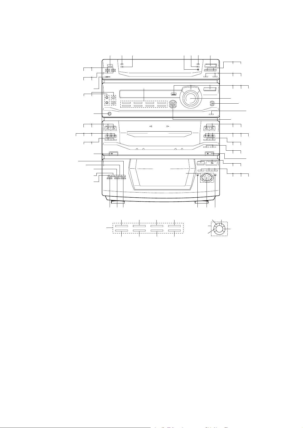
– FRONT PANEL –
SECTION 1
GENERAL
$¢
%ª ^º
%¶ %•
%§
%¢ %∞
%£
%¡ %™
$ª$• %º
$§
$¶
$∞
$£
$™
$¡
$º
123 4 6 7
A
see A
see B
5
B
89
!º !¡
!™
!£ !¢
!∞
!§
!¶
!•
!ª @º
@¡ @™ @£
@¢ @∞
@§ @¶
@ª #º
#¡ #™ #£
@•
A
1 POWER button
2 DISPLAY/DEMO button
3 SPECTRUM ANAL YZER button
4 ENTER/NEXT button
5 TUNER MEMORY button
6 TUNING MODE button
7 TUNER/BAND button
8 TUNING – button
9 TUNING + button
!º PTY button (AEP, UK model)
!¡ STEREO/MONO button
!™ EFFECT button
!£ GROOVE button
!¢ FUNCTION button
!∞ VOLUME knob
!§ SUPER WOOFER button
!¶ SUPER W MODE (XB44K model)
!• GEQ button
!ª DECK B ª (play) button
@º DECK B · (play) button
@¡ DECK B p (stop) button
@™ DECK B 0 (backward) button
@£ DECK B ) (forward) button
@¢ DECK B P (pause) button
^¡ ^™ ^£ ^¢
^• ^∞
^¶ ^§
@∞ DECK B r REC button
@§ H SPEED DUB button
@¶ CD SYNC button
@• DECK B 6 EJECT button
@ª CD 6 OPEN button
#º CD · (play) button
#¡ DISK SKIP button
#™ CD P (pause) button
#£ CD p (stop) button
#¢ CD ) (forward) button
#∞ ≠ AMS ± knob
#§ CD 0 (backward) button
#¶ FLASH button
#• LOOP button
#ª NON-STOP button
$º DISC 1 button
$¡ DISC 2 button
$™ DISC 3 button
$£ DISC 4 button
$¢ DISC 5 button
$∞ DECK A 6 EJECT button
$§ DIRECTION button
$¶ DOLBY NR button
$• DECK A p (stop) button
#¢
#∞#§#• #¶#ª
&™ ^ª
B
&¡
&º
$ª DECK A 0 (backward) button
%º DECK A ) (forward) button
%¡ DECK A ª (play) button
%™ DECK A · (play) button
%£ PHONES jack
%¢ MIC1, MIC2 jack
%∞ MIC LEVEL, ECHO LEVEL knob
%§ SLEEP button
%¶ DAILY 1 button
%• DAILY 2 button
%ª t / CLOCK SET button
^º REC button
^¡ WAVE button
^™ SURROUND button
^£ P FILE MEMORY button
^¢ GEQ CONTROL button
^∞ ENTER button
^§ KEY CONTROL ( n) button
^¶ KEY CONTROL ( ˜) button
^• KARAOKE PON/MPX button
^ª PLAY MODE button
&º REPEAT button
&¡ EDIT button
&™ 1/ALL DISCS button
— 5 —
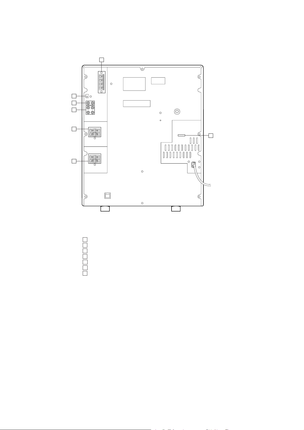
– BACK PANEL –
⁄‚⁄
⁄‚‡
⁄‚fl
⁄‚fi
⁄‚›
⁄‚‹
IN
OUT
⁄‚¤
⁄‚⁄ ANTENNA terminal
⁄‚¤ VOLTAGE SELECTOR switch (E, AR model)
⁄‚‹ SPEAKER terminal
⁄‚› SURROUND SPEAKER terminal (XB33K model)
⁄‚fi VIDEO/MD (AUDIO) jack
⁄‚fl PHONO jack
⁄‚‡ CD DIGITAL OUT connector
— 6 —

This section is extracted
from instruction manual.
— 7 —

— 8 —

— 9 —

• This set can be disassembled in the order shown below.
SECTION 2
DISASSEMBLY
UPPER
CASE
(Page 10)
Note: Follow the disassembly procedure in the numerical order given.
FRONT PANEL
SECTION
(Page 11)
MAIN
SECTION
(Page 12)
TAPE MECHANISM
DECK SECTION
(Page 13)
CD LID ASSY
SECTION
(Page 14)
MAIN BOARD/KEY CON
BOARD
(Page 11)
2-1. UPPER CASE
CD MECHANISM
DECK SECTION
(Page 12)
AUDIO BOARD
(Page 17)
CASSETTE
LID ASSY
(Page 13)
PANEL (A)/(B)
SUB ASSY
(Page 14)
BASE UNIT
(Page 15)
DISC TABLE
(Page 15)
CAPSTAN MOTOR
(Page 17)
BD BOARD
(Page 16)
OPTICAL
PICK-UP
(Page 16)
SLED
MOTOR
(Page 16)
1
Three screws
(case 3 point)
3
Upper case
1
Three screws
(case 3 point)
— 10 —
2
Seven screws
(BVTT 3
×
6)
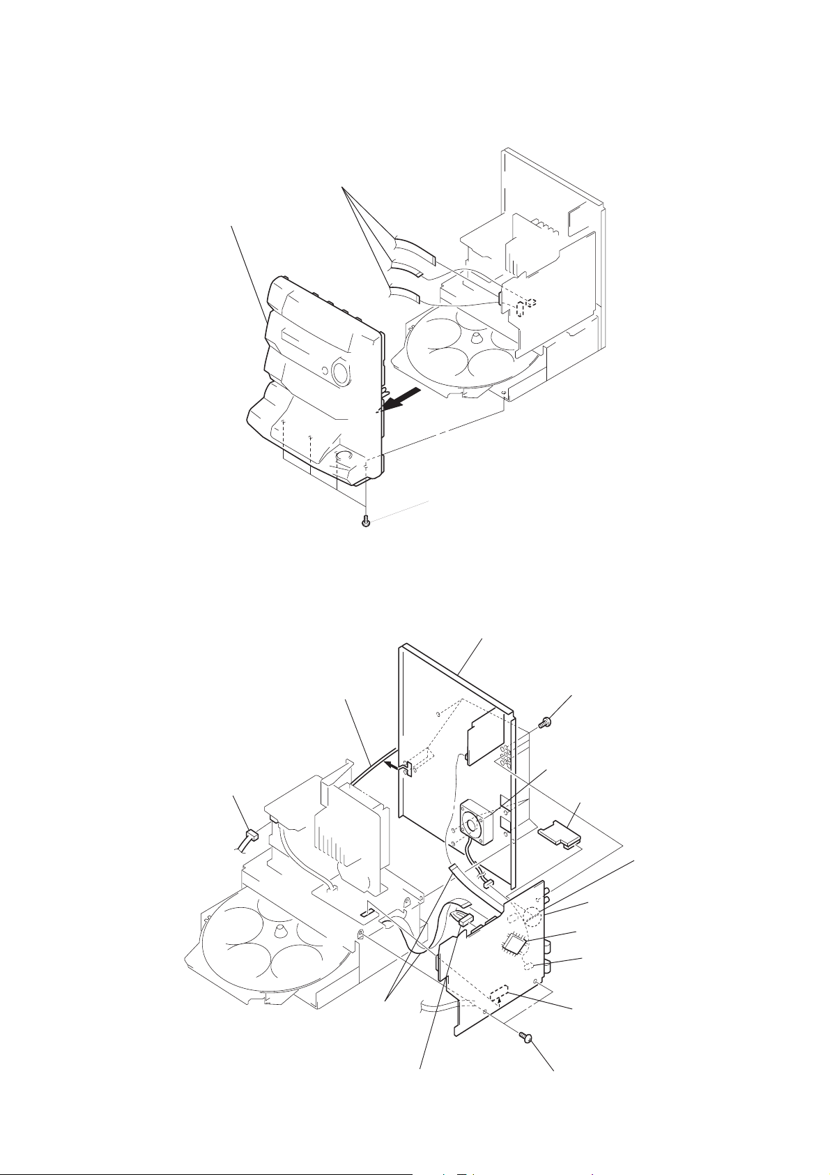
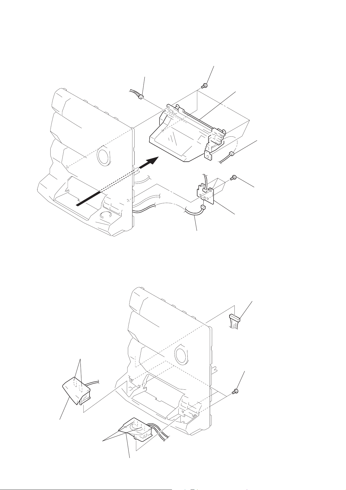
2-2. FRONT PANEL SECTION
3
Front panel section
1
Three flat wires
(CN102, 205, 206)
2
Four screws
(BVTP 3 x 8)
2-3. MAIN BOARD/KEY-CON BOARD
5
Power cord
3
Connector
(CN901)
1
(CN1,202)
Two flat wires
6
Back panel
4
Twelve screws
(BVTP 3 × 8)
Fan is for (XB44K)
!¡
KEY-CON board
0
MAIN board
IC201
9
Connector
(CN105)
(XB44K)
8
Connector
(CN101)
(Remove soldering)
2
Connector
(CN203)
— 11 —
7
Two screws
(BVTP 3 × 8)

2-4. MAIN SECTION
)
)
3
Two screws
(BVTP 3 × 8)
2
Connector
(CN203)
1
Flat wire (CN202)
4
Main section
3
(BVTP 3 × 8
3
(BVTP 3 × 8
Screw
Two screws
2-5. CD MECHANISM DECK SECTION
3
Five screws
(BVTP 3 × 8)
4
CD mechanism
deck section
2
Flat wire and
lead wire
— 12 —
1
Open the clamp.

2-6. TAPE MECHANISM DECK SECTION
)
4
Three screws
(BVTP 2.6 × 8)
3
Two flat wires
(CN601, 1001)
4
(BVTP 2.6 × 8)
A
Three screws
5
Remove the tape mechanism
deck section to direction of the arrow A.
2
Open the
cassette lid.
2-7. CASSETTE LID ASSY
1
Two springs
1
Push the
two buttons.
3
Two brackets
2
Two screws
(BVTP 2.6 × 8
4
Cassette lid assy
— 13 —
)
)
2-8. CD LID ASSY SECTION
5
Connector
(CN671)
6
Four screws
(BVTP 2.6 × 8)
7
CD lid assy
4
Connector
(CN661)
2
Four screws
(BVTP 2.6 × 8
2-9. PANEL (A) / (B) SUB ASSY
3
Two claws
1
Connector
(CN642)
3
CD-B1 SW board
1
Connector
(CN612)
2
Four screws
(BVTP 2.6 × 8
4
Panel (A) sub assy
5
Two claws
6
Panel (B) sub assy
— 14 —

e
2-10. BASE UNIT
2
Boss
3
Base unit
1
Yoke bracket
2-11. DISC T ABLE
Note:
When the disc table is installed, adjust the positions
of roller cam and mark z as shown in the figure,
then set to the groove of disc table.
A
1
Screw
(BVTP 3 × 8)
2
Bracket (BU)
1
Screw
(BVTP 3 × 8)
3
Step screw
4
Disc tabl
— 15 —
A

)
2-12. BD BOARD
s
6
the four solders.
1
(PTPWH M2.6 × 6)
3
5
Screw
(BVTP 2.6 × 8)
Removal
Two screws
Two springs
1
Two screws
(PTPWH M2.6 × 6
2
Optical pick-up
section
3
Two springs
4
Flat wire
(CN101)
7
BD board
2-13. OPTICAL PICK-UP, SLED MOTOR
3
Optical pick-up
Limit switch
4
Two screw
(P 2 × 3)
2
Sled shaft
1
Claw
— 16 —
5
Sled motor

2-14. AUDIO BOARD
o
4
Four screws
(BTP 2.6 × 4)
5
Audio board
1
Connector
(CN651)
2
Two rivets
3
Break the soldering of tw
flexible flat cables.
2-15. CAPSTAN MOTOR
1
Break the soldering of
motor lead.
4
Removal the capstan motor
to direction of the arrow.
3
Claw
2
Two screws
(BTP 2.6 × 8)
— 17 —
5
Hang the
two belts.

SECTION 3
TEST MODE
[MC Cold Reset]
• The cold reset clears all data including preset data stored in the
RAM to initial conditions. Execute this mode when returning the
set to the customer.
Procedure:
1. Press three buttons GROOVE , ENTER/NEXT , and
DISC 1 simultaneously.
2. The fluorescent indicator tube becomes blank instantaneously,
and the set is reset.
[CD Delivery Mode]
• This mode moves the pickup to the position durable to vibration.
Use this mode when returning the set to the customer after repair.
Procedure:
1. Press POWER button to turn the set ON.
2. Press PLAY MODE button and POWER button simulta-
neously.
3. A message “LOCK” is displayed on the fluorescent indicator
tube, and the CD delivery mode is set.
[MC Hot Reset]
• This mode resets the set with the preset data kept stored in the
memory. The hot reset mode functions same as if the power cor d
is plugged in and out.
Procedure:
1. Press three buttons GROOVE , ENTER/NEXT , and
DISC 2 simultaneously.
2. The fluorescent indicator tube becomes blank instantaneously,
and the set is reset.
[LED and Fluorescent Indicator Tube All Lit, Key Check
Mode]
Procedure:
1. Press three b uttons GROOVE , ENTER/NEXT , and DISC 3
simultaneously .
2. LEDs and fluorescent indicator tube are all turned on.
Press DISC 2 button, and the key check mode is activated.
3. In the key check mode , the fluorescent indicator tube displays
“K 1 J0 V0”. Each time a b utton is pressed, “K”value increases.
However, once a button is pressed, it is no longer taken into
account.
“J” Value increases like 1, 2, 3 ... if rotating
≠ AMS ± knob in “+” direction, or it decreases like 0,
9, 8 ... if rotating in “–” direction.
“V” Value increases like 1, 2, 3 ... if rotating VOLUME knob
in “+” direction, or it decreases like 0, 9, 8 ... if rotating in “–”
direction.
4. To exit from this mode, press three buttons in the same manner
as step 1, or disconnect the power cord.
[Sled Servo Mode]
• This mode can run the CD sled motor freely. Use this mode, for
instance, when cleaning the pickup.
Procedure:
1. Select the function “CD”.
2. Press three buttons GROOVE , ENTER/NEXT , and
FLASH simultaneously.
3. The Sled Servo mode is selected, if “CD” is flashing on the
fluorescent indicator tube.
4. With the CD in stop status, press ) button in CD section to
move the pickup to outside track, or 0 button to inside track.
5. To exit from this mode, perform as follows:
1) Move the pickup to the most inside track.
2) Press three buttons in the same manner as step 2.
Note:
• Always mov e the pickup to most inside track when exiting fr om
this mode. Otherwise, a disc will not be unloaded.
• Do not run the sled motor excessi vely, otherwise the gear can be
chipped.
[Change-over of AM T uner Step between 9kHz and 10kHz]
• A step of AM c hannels can be changed over betw een 9kHz and
10kHz.
Procedure:
1. Press POWER button to turn the set ON.
2. Select the function “TUNER”, and press TUNER/BAND
button to select the BAND “AM”.
3. Press POWER button to turn the set OFF.
4. Pr ess ENTER/NEXT and POWER buttons sim ultaneously,
and the display of fluorescent indicator tube changes to “AM
9k STEP” or “AM 10k STEP”, and thus the channel step is
changed over.
— 18 —

[Aging Mode]
This mode can be used for operation check of CD section and tape
deck section.
• If an error occurred:
The aging operation stops.
• If no error occurs:
The aging operation continues repeatedly.
1. Aging Mode in CD Section
1-1. Operating Method of Aging Mode
1. Set discs in DISC 1 and DISC 3 trays.
2. Select the function “CD”.
3. Press three buttons GROOVE , ENTER/NEXT , and
DISC 5 simultaneously.
4. The aging mode is activated, if a roulette mark on the
fluorescent indicator tube is flashing.
5. In the aging mode, the aging is executed in a sequence given
in “1-2. Operation during Aging Mode”.
The aging continues unless an alarm occurred.
6. To e xit from the aging mode, press POWER button to tur n
the set OFF.
• If a button other than buttons in the CD section is pressed during
aging, the aging in the CD section is finished.
• To e xecute aging to the tape dec k section successively , press ·
button in the deck A.
“A GING” is displayed on the fluorescent indica tor tube. (For the
aging in tape deck, see “2. Aging Mode in Tape Deck Section”.
8. To exit from the aging mode, press POWER button to turn
the set OFF.
2-2. Operation during Aging Mode
In the aging mode, the program is executed in the following
sequence.
1. A tape on FWD side is played for one minute.
2. PAUSE STOP is made.
3. Recording is made for 3 minutes. (For the deck not having
the record function, the play is executed.)
4. FF is executed up to the end of tape.
5. A tape is reversed, and the tape on REV side is played for
one minute.
6. PAUSE STOP is made.
7. Recording is made for 3 minutes. (For the deck not having
the record function, the play is executed.)
8. FF is executed up to the end of tape.
9. Steps 1 through 8 are executed for the other deck.
10. Steps 1 through 9 are repeated unless an alarm occurred.
2-3. Deck Selection Sequence
• During the aging mode, decks are selected in the following
sequence:
Deck A (FWD) → Deck A (REV)
↑↓
Deck B (REV) ← Deck B (FWD)
1-2. Operation during aging Mode
In the aging mode, the program is executed in the following
sequence.
1. The disc tray turns to select a disc. (For a disc selection
sequence, see Section 1-3.)
2. TOC of disc is read.
3. The pickup accesses to the last track.
4. Steps 1 through 3 are repeated.
1-3. Disc Selection Sequence
• During the aging mode, discs are selected in the following
sequence:
Disc 1 → Disc 3
↑↓
Disc 3 ← Disc 1
2. Aging Mode in Tape Deck Section
2-1. Operating Method of Aging Mode
1. Load a commercially available 10-minute tape into the decks
A and B respectively.
(If a 10-minute tape is not available, another tape may be
used but a cycle time will be longer.)
2. Select the function “TAPE”.
3. Rewind tapes in advance by pressing 0 button
respectively on decks A and B.
4. Press three buttons GROOVE , ENTER/NEXT , and
DISC 5 simultaneously.
5. Press · button on deck A. (This b utton triggers the aging
mode.)
6. The aging mode is activated if “AGING A” is displayed on
the fluorescent indicator tube.
7. In the ag ing mode, the aging is executed in a sequence giv en
in “2-2. Operation during Aging Mode”.
The aging continues unless an alarm occurred.
— 19 —
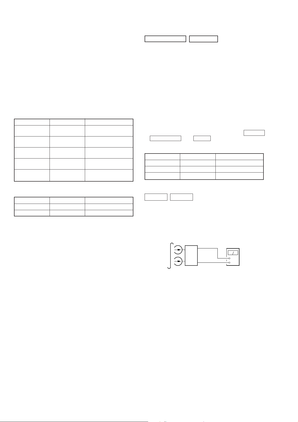
SECTION 4
set
main board
CN207
Pin
1
(L-CH)
Pin
3
(R-CH)
main board
CN207
Pin
2
+
–
level meter
test tape
P-4-A100
(10KHz, –10dB)
SECTION 5
MECHANICAL ADJUSTMENTS
PRECAUTION
1. Clean the following parts with a denatured-alcohol-moistened
swab:
record/playback head pinch roller
erase head rubber belts
capstan idlers
2. Demagnetize the record/playback head with a head
demagnetizer.
3. Do not use a magnetized screwdriver for the adjustments.
4. After the adjustments, apply suitable locking compound to the
parts adjusted.
5. The adjustments should be performed with the rated power
supply voltage unless otherwise noted.
• Tor que Measurement
Mode Torque Meter Meter Reading
Forward CQ-102C
Forward
Back Tension (0.026 – 0.082 oz·inch)
Reverse CQ-102RC
Reverse
Back Tension (0.026 – 0.082 oz·inch)
FF, REW CQ-201B
CQ-102C
CQ-102RC
36 to 61g·cm
(0.50 – 0.84 oz·inch)
2 to 6g·cm
36 to 61g·cm
(0.50 – 0.84 oz·inch)
2 to 6g·cm
61 to 143g·cm
(0.85 – 1.98 oz·inch)
ELECTRICAL ADJUSTMENTS
DECK SECTION
1. Demagnetize the record/playback head with a head
demagnetizer. (Do not bring the head demagnetizer close to
the erase head.)
2. Do not use a magnetized screwdriver for the adjustments.
3. After the adjustments, apply suitable locking compound to the
parts adjust.
4. The adjustments should be performed with the rated power
supply voltage unless otherwise noted.
5. The adjustments should be performed in the order given in this
service manual. (As a general rule, playback circuit adjustment
should be completed before performing recording circuit
adjustment.)
6. The adjustments should be performed for both L-CH and RCH.
7. Switches and controls should be set as follows unless otherwise
specified.
8. Set to test mode. (Press key switch same time GROOVE
ENTER/NEXT and DISC 4 button.)
• Test Tape
Tape Signal Used for
P-4-A100 10kHz, –10 dB Azimuth Adjustment
WS-48B 3kHz, 0dB Tape Speed Adjustment
P-4-L300 315Hz, 0dB Level Adjustment
0dB=0.775V
• Tape T ension Measurement
Mode Tension Meter Meter Reading
Forward CQ-403A more than 100g (3.52 oz)
Reverse CQ-403R more than 100g (3.52 oz)
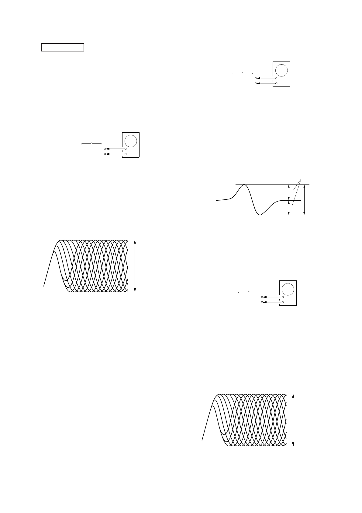
Record/Playback Head Azimuth Adjustment
DECK A DECK B
Note: Perform this adjustments for both decks
Procedure:
1. Mode: Playback (FWD)
— 20 —

2. Turn the adjustment screw and check output peaks. If the peaks
e
+
–
set
test tape
WS-48B
(3 kHz, 0 dB)
main board
CN207 (Pin
1
: L-CH)
(Pin
3
:R-CH)
frequency counter
+
–
set
test tape
P-4-L300
(315 Hz, 0 dB)
main board
CN207 (Pin
1
: L-CH)
(Pin
3
: R-CH)
level meter
do not match for L-CH and R-CH, turn the adjustment screw
so
that outputs match within 1dB of peak.
output
level
within
1dB
L-CH
peak
R-CH
peak
within
1dB
Screw
position
L-CH
peak
Screw
position
R-CH
peak
3. Mode: Playback (FWD)
test tape
P-4-A100
(10kHz, –10dB)
L-CH
main
board
CN207
set
R-CH
in phase 45°90°135°180
pin
1
pin
2
L
R
pin
3
waveform of oscilloscope
good
oscilloscop
V
wrong
H
°
4. Repeat steps 1 to 3 in playback (REV) mode.
5. After the adjustments, apply suitable locking compound to the
pats adjusted.
Adjustment Location: Record/Playback Head (Deck A and B)
and main board.
Tape Speed Adjustment DECK A
Notes: • Start the T a pe Speed adjustment as below after setting to the test
mode.
• In the test mode, the tape speed is high during pressing the
H. SPEED DUB button.
Procedure:
1. Turn the power switch on.
2. Press the GROOVE button, ENTER/NEXT button and
DISC 4 button simultaneously.
To exit from the test mode, press the POWER button.
Mode: Playback (FWD)
1. Insert the WS-48B into the deck A and the blank tape into the
deck B.
2. Press the REC button and · button on the deck B. Then
the deck B is at recording mode.
3. Set the deck A to playback mode.
4. Keep pressing the H. SPEED DUB button in playback mode.
Then at HIGH speed mode.
5. Adjust RV652 on the AUDIO board do that frequency counter
reads 6,000 ± 180 Hz.
6. Take off the H. SPEED DUB button.
Then at NORMAL speed mode.
7. Adjust RV651 on the AUDIO board so that frequency counter
reads 3,000 ± 90 Hz.
8. Frequency difference between deck A and deck B the be ginning
of the tape should be within ± 1.5%.
Adjustment Location: AUDIO board
Sample Value of Wow and flutter
W.RMS (JIS) within 0.3%
(test tape: WS-48B)
forward
Playback level Adjustment DECK A DECK B
Procedure:
Mode: Playback (FWD)
reverse
Deck A is RV311 (L-CH) and RV411 (R-CH), Deck B is RV301
(L-CH) and RV401 (R-CH) so tha t adjustment within adjustment
level as follows.
Adjustment Level:
CN207 PB level: 301.5 to 338.3 mV (–8.2 to –7.2 dB) level
difference between the channels: within ±0.5 dB
Adjustment Location: AUDIO and main boards
— 21 —

Record Bias Current Adjustment DECK B
r
r
Procedure:
1. Mode: record
Pin
6
(L-CH) of IC1501 on the main board.
Pin #¶ (L-CH) of IC1501 on the main board.
1) 315 Hz
2) 10 kHz
AF OSC
attenuator
Pin 2 (GND) of ICN207 on the main board.
50 mV (–23.8 dB)
600
Ω
set
2. Mode: Playback
recorded
portion
level mete
blank tape
CN-123
Adjustable limits:
CN207 PB level: 47.3 to 53.1 mV (–24.3 to –23.3 dB)
Adjustment Location: main board
[MAIN BOARD] (Component Side)
RV1501
IC1501
RV1551
IC201
CN207
IC301
RECORD LEVEL
CN205
1
3
+
–
: L-CH)
: R-CH)
set
CN207 (Pin
(Pin
Confirm playback that the signal recorded in step 1 becomes adjustable
limits as follows.
If these levels are not adjustable limits, adjust the RV341 (L-CH) and
RV441 (R-CH) on the AUDIO board to repeat steps 1 and 2.
Adjustable limits: Playback output of 315 Hz to playback output
of 10kHz: 0±0.5 dB
Adjustment Location: AUDIO and main boards
Record Level Adjustment DECK B
Procedure:
1. Mode: record
Pin
6
(L-CH) of IC1501 on the main board.
Pin #¶ (R-CH) of IC1501 on the main board.
AF OSC
315 Hz, 50 mV (–23.8 dB)
600
attenuator
Ω
blank tape
CS-123
set
[AUDIO BOARD] (Conductor Side)
RECORD
BAIS
L
RV301
RV401®R
PB LEVEL
R
®
L
RV441RV341
– DECK B –
TAPE SPEED
(NORMAL)
RV651
®
PB
LEVEL
– DECK A –
RV311
RV411
(HIGH)
RV652
®
L
®
R
®
2
(GND) of CN207 on the main board.
Pin
2. Mode: Playback
recorded
portion
set
CN207 (Pin
(Pin
level mete
1
: L-CH)
3
: R-CH)
+
–
Confirm playback that the signal recorded in step 1 becomes
adjustable limits as follows.
If these levels are not adjustable limits, adjust the RV1501 (L-CH)
and RV1551 (R-CH) on the main board to repeat steps 1 and 2.
— 22 —
CD SECTION
V
+
–
BD board
TP (FEO)
TP (VC)
oscilloscope
+
–
BD board
TP (RF)
TP (VC)
oscilloscope
VOLT/DIV: 200 mV
TIME/DIV: 500 ns
level:
1.3
±
0.3Vp-p
Note:
1. CD Block is basically designed to operate without adjustment.
Therefore, check each item in order given.
2. Use YEDS-18 disc (3-702-101-01) unless otherwise indicated.
3. Use an oscilloscope with more than 10MΩ impedance.
4. Clean the object lens b y an applicator with neutral detergent when the
signal level is low than specified value with the following checks.
5. Adjust the focus bias adjustment when optical block is replaced.
Focus Bias check
oscilloscope
(DC range)
BD board
TP (RF)
VC
Procedure:
1. Connect oscilloscope to test point TP (RF). (GND terminal :
VC)
2. Turned Power switch on.
3. Put disc (YEDS-18) in and playback.
4. Confirm that the shape “
≈” can be clearly distinguished at the
center of the waveform and check the RF signal level.
+
–
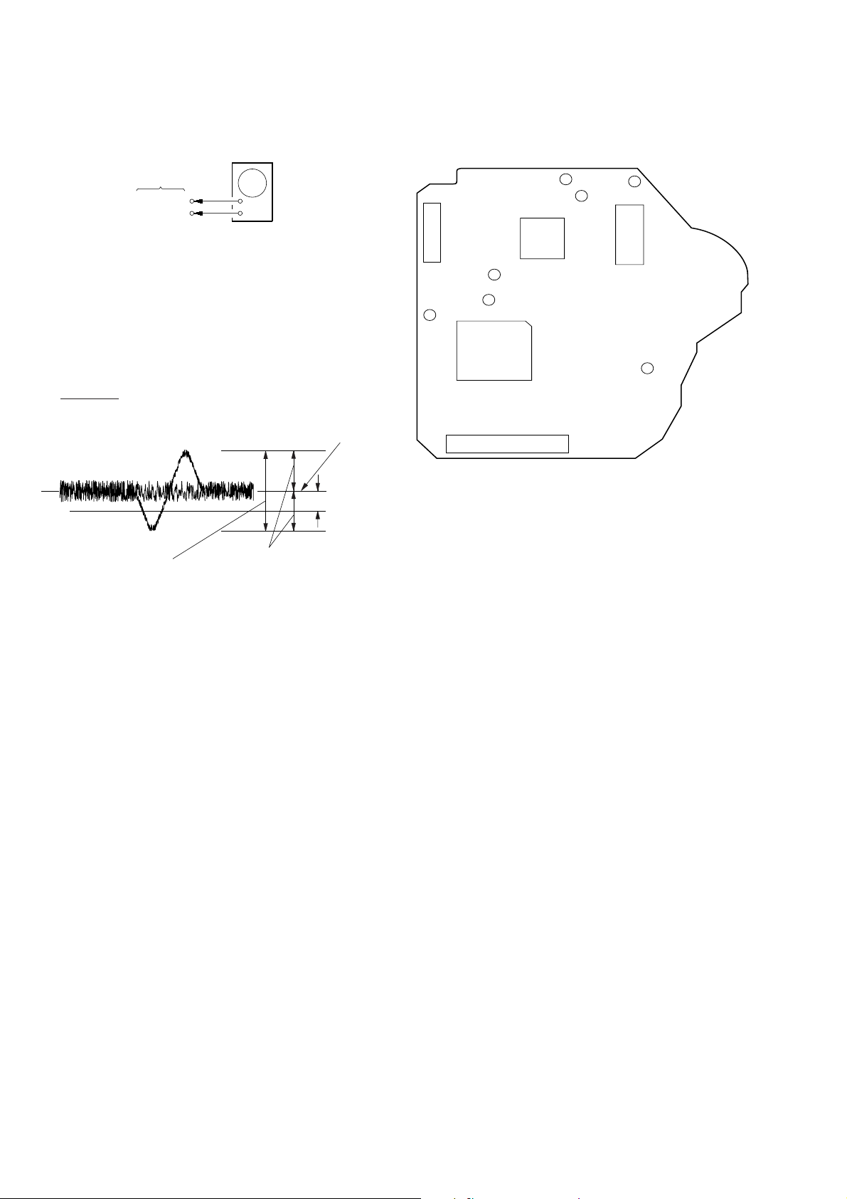
S Curve Check
Procedure:
1. Connect oscilloscope to test point TP (FEO).
2. Connect between test point TP (FOK) and GND by lead wire.
3. Turn Power switch on.
4. Put disc (YEDS-18) in and turned Power switch on again and
actuate the focus search. (actuate the focus search when disc
table is moving in and out.)
5. Check the oscilloscope waveform (S-curve) is symmetrical
between A and B. And confirm peak to peak level within 3±1
Vp-p.
S-curve wavef orm
symmetry
A
B
within 3
±
1 Vp-p
• RF signal
VOLT/DIV: 200 m
TIME/DIV: 500 ns
level:
±
0.3Vp-p
1.3
6. After check, remove the lead wire connected in step 2.
Notes: • Tr y to measure sever al times to mak e sure than the ratio of A : B
or B : A is more than 10 : 7.
• Take sweep time as long as possible and light up the brightness
to obtain best waveform.
RF Level Check
Procedure:
1. Connect oscilloscope to test point TP (RF) on BD board.
2. Turned Power switch on.
3. Put disc (YEDS-18) in and playback.
4. Confirm that oscilloscope waveform is clear and check RF signal
level is correct or not.
Note: Clear RF signal waveform means that the shape “≈” can be
clearly distinguished at the center of the waveform.
• RF signal
— 23 —
E-F Balance (1 Track Jump) check
)
(Without remote commander)
oscilloscope
BD board
TP (TEO)
TP (VC)
+
–
Procedure:
1. Connect oscilloscope to test point TP (TEO) on BD board.
2. Turned Power switch on.
3. Put disc (YEDS-18) in to play the number five track.
4. Press the “P (P ause)” b utton. (Becomes the 1 track jump mode)
5. Check the level B of the oscilloscope's waveform and the A
(DC voltage) of the center of the Traverse waveform.
Confirm the following:
A – B
2 (A + B)
× 100 = ±7 (%)
Adjustment Location:
[BD BOARD] (Conductor Side)
TP
(RF)
TP
(FOK)
CNU101
TP
(GND)
IC103
IC101
TP (TEO)
TP (FEO)
TP
(VC)
IC
I02
1 track jump waveform
0V
level : 500 mV
±
100 mVp-p
Center of the waveform
B
A (DC voltage
symmetry
CNU102
— 24 —
 Loading...