

SONY HCD-FC8, HCD-FC9 Service Manual

HCD-FC8/FC9
SERVICE MANUAL
Ver 1.0 2003. 08
HCD-FC8/FC9 are the amplifier, D VD/SA CD and
tuner section in DAV-FC8/FC9 .
AUDIO POWER SPECIFICATIONS POWER
OUTPUT AND TOTAL HARMONIC
DISTORTION:
With 4 ohm loads, both channels drive n, fr om 20 –
20,000 Hz; rated 75 watts per channel minimum RMS
power, with no more than 0.7 % total harmonic
distortion. (from 250 milli watts to rated output)
Amplifier section
Stereo mode 100 W + 100 W (4 ohms
Surround mode Front:
* Depending on the sound field settings and the sour ce,
there may be no sound output.
Inputs VIDEO 1:
Outputs
at 1 kHz, THD 10 %)
100
W +
100
centre*:
100
Surround*:
100
W (4 ohms at 1 kHz,
THD 10 %)
Subwoofer*:
(4 ohms at 100 Hz, THD
10 %)
Sensitivity: 150 mV
Impedance: 50 kilohms
VIDEO 2:
Sensitivity: 300 mV
Impedance: 50 kilohms
VIDEO 1 (AUDIO
OUT):
Voltage: 1 V
Impedance: 1 kilohm
PHONES:
Accepts stereo
headphones only.
W
100
100
W
W +
W
Super Audio CD/DVD system
Laser emiconductor laser
Signal format system NTSC or NTSC/PAL
Frequency response (at 2 CH STEREO mode)
Harmonic distortion Less than 0.03 %
Tuner section
System PLL quartz-locked digital
FM tuner section
Tuning range
Antenna FM wire antenna
Antenna terminals 75 ohms, unbalanced
Intermediate frequency 10.7 MHz
AM tuner section
Tuning range
North American models: 531 – 1,710 kHz (with the
Other models: 531 – 1,602 kHz (with the
Antenna AM loop antenna
Intermediate frequency 450 kHz
SPECIFICATIONS
S
(Super Audio CD/DVD:
= 650 nm)
λ
(CD: = 780 nm)
Emi
continuous
DVD (PCM): 2 Hz to
22 kHz (±1.0 dB)
CD: 2 Hz to 20 kHz
(±1.0 dB)
synthesizer system
87.5 – 108.0 MHz
(100 kHz step)
interval set at 9 kHz)
530 – 1,710 kHz (with the
interval set at 10 kHz)
interval set at 9 kHz)
530 – 1,710 kHz (with the
interval set at 10 kHz)
US Model
Canadian Model
Model Name Using Similar Mechanism HCD-FC7
Mechanism T ype
Base Unit Name DVBU16
Optical Pick-up Name
Video section
Inputs Video: 1 Vp-p 75 ohms
Outputs Video: 1 Vp-p 75 ohms
λ
ssion duration:
General
Power requirements
Power consumption
Dimensions (approx.) 380 70 345 mm
Mass (approx.) 4.8 kg (10 lb 10 oz)
Operating temperature 5°C to 35°C (41°F to 95°F)
Operating humidity 5 % to 90 %
Design and specification are subject to change without
notice.
CDM69-DVBU16
TDP022W
S video:
Y: 1 Vp-p 75 ohms
C: 0.286 Vp-p 75 ohms
COMPONENT:
Y: 1 Vp-p 75 ohms
PB/CB, PR/CR: 0.7 Vp-p
75 ohms
120 V AC, 60 Hz
135 W
(
15 2
(w/h/d) incl. projecting
parts
SACD/DVD RECEIVER
HCD-FC8/FC9
HCD-FC9
××
7
× ×
/8 13 5/8 inches)
9-961-134-01
2003H1678-1
© 2003.08
Sony Corporation
Home Audio Company
Published by Sony Engineering Corporation
HCD-FC8/FC9
r
Laser component in this product is capable of emitting radiation
exceeding the limit for Class 1.
This appliance is classified as
a CLASS 1 LASER product.
The CLASS 1 LASER
PRODUCT MARKING is
located on the rear exterior.
CAUTION
Use of controls or adjustments or performance of procedures
other than those specified herein may result in hazardous
radiation exposure.
Notes on chip component replacement
•Never reuse a disconnected chip component.
• Notice that the minus side of a tantalum capacitor may be
damaged by heat.
Flexible Circuit Board Repairing
•Keep the temperature of soldering iron around 270˚C
during repairing.
• Do not touch the soldering iron on the same conductor of the
circuit board (within 3 times).
• Be careful not to apply force on the conductor when soldering
or unsoldering.
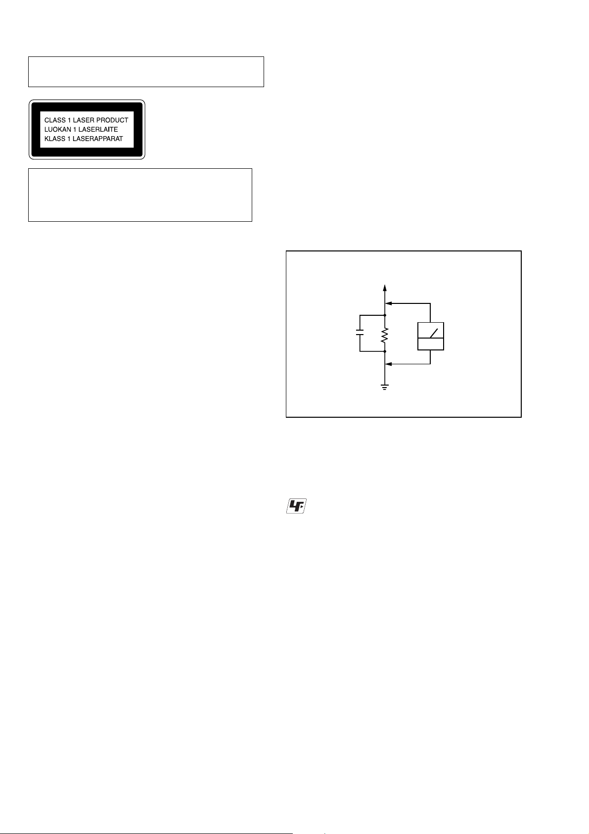
LEAKAGE
The AC leakage from any exposed metal part to earth Ground and
from all exposed metal parts to any exposed metal part having a
return to chassis, must not exceed 0.5 mA (500 microampers).
Leakage current can be measured by any one of three methods.
1. A commercial leakage tester, such as the Simpson 229 or RCA
WT -540A. Follo w the manufacturers’ instructions to use these
instruments.
2. A battery-operated AC milliammeter. The Data Precision 245
digital multimeter is suitable for this job.
3. Measuring the voltage drop across a resistor by means of a
VOM or battery-operated A C voltmeter . The “limit” indication
is 0.75 V, so analog meters must have an accurate low-v oltage
scale. The Simpson 250 and Sanwa SH-63Trd are e xamples of
a passive VOM that is suitable. Nearly all battery operated
digital multimeters that have a 2V AC range are suitable. (See
Fig. A)
To Exposed Metal
Parts on Set
0.15µF
1.5k
Ω
AC
voltmete
(0.75V)
SAFETY CHECK-OUT
After correcting the original service problem, perform the following
safety checks before releasing the set to the customer:
Check the antenna terminals, metal trim, “metallized” knobs, screws,
and all other exposed metal parts for A C leakage. Check leakage as
described below.
Earth Ground
Fig. A. Using an AC voltmeter to check AC leakage.
Unleaded solder
Boards requiring use of unleaded solder are printed with the leadfree mark (LF) indicating the solder contains no lead.
(Caution: Some printed circuit boards may not come printed with
the lead free mark due to their particular size.)
: LEAD FREE MARK
Unleaded solder has the following characteristics.
• Unleaded solder melts at a temperature about 40°C higher than
ordinary solder.
Ordinary soldering irons can be used but the iron tip has to be
applied to the solder joint for a slightly longer time.
Soldering irons using a temperature regulator should be set to
about 350°C.
Caution: The printed pattern (copper foil) may peel away if the
heated tip is applied for too long, so be careful!
• Strong viscosity
Unleaded solder is more viscous (sticky, less prone to flow) than
ordinary solder so use caution not to let solder bridges occur such
as on IC pins, etc.
• Usable with ordinary solder
It is best to use only unleaded solder but unleaded solder may
also be added to ordinary solder.
SAFETY-RELATED COMPONENT WARNING!!
COMPONENTS IDENTIFIED BY MARK 0 OR DOTTED LINE WITH
MARK 0 ON THE SCHEMATIC DIAGRAMS AND IN THE PARTS
LIST ARE CRITICAL TO SAFE OPERATION. REPLACE THESE
COMPONENTS WITH SONY PARTS WHOSE PART NUMBERS
APPEAR AS SHOWN IN THIS MANUAL OR IN SUPPLEMENTS
PUBLISHED BY SONY.
2
ATTENTION AU COMPOSANT AYANT RAPPORT
À LA SÉCURITÉ!
LES COMPOSANTS IDENTIFÉS P AR UNE MARQUE 0 SUR LES
DIAGRAMMES SCHÉMA TIQUES ET LA LISTE DES PIÈCES SONT
CRITIQUES POUR LA SÉCURITÉ DE FONCTIONNEMENT. NE
REMPLACER CES COMPOSANTS QUE PAR DES PIÈSES SONY
DONT LES NUMÉROS SONT DONNÉS DANS CE MANUEL OU
DANS LES SUPPÉMENTS PUBLIÉS PAR SONY.

TABLE OF CONTENTS
HCD-FC8/FC9
1. SERVICING NOTE ·························································· 4
2. GENERAL ·········································································· 7
3. DISASSEMBLY ······························································ 10
3-1. FRONT PANEL SECTION,
SIDE PANEL (L)/(R) SECTION································· 11
3-2. DDCON BOARD, LED BOARD, FL BOARD ·········· 12
3-3. KEY BOARD ······························································ 12
3-4. POWER BOARD ························································· 13
3-5. AMP BOARD······························································ 13
3-6. DVD BOARD, DC FAN·············································· 14
3-7. CD MECHANISM DECK (CDM69-DVBU16) ········· 15
3-8. SELECTOR BOARD, VIDEO BOARD,
LF BOARD ·································································· 16
3-9. AUDIO BOARD, S-VIDEO BOARD ························· 16
3-10. BASE UNIT (DVBU16) ············································ 17
3-11. PICK-UP UNIT (TDP022W)····································· 17
3-12. SW BOARD, BRACKET (TOP) ASSY ···················· 18
3-13. RELAY BOARD ························································ 18
3-14. MOTOR (STOCKER) ASSY (STOCKER)(M761)··· 19
3-15. MOTOR (STOCKER) ASSY (ROLLER)(M781) ·····19
3-16. MOTOR (STOCKER) ASSY (MODE)(M771) ········· 20
3-17. RUBBER ROLLER (SLIDER) ASSY ······················· 20
3-18. TIMING BELT (FRONT/REAR) ······························ 21
3-19. CAM (GEAR) ···························································· 21
3-20. SENSOR BOARD ····················································· 22
4. ASSEMBLY
4-1. HOW TO INSTALL THE CAM (EJECT LOCK) ······· 23
4-2. HOW TO INSTALL THE CAM (GEAR) ···················23
4-3. HOW TO INSTALL THE GEAR (MODE 2)·············· 24
4-4. HOW TO INSTALL THE GEAR (MODE CAM)······· 24
4-5. HOW TO INSTALL
THE ROTARY ENCODER (S702),
GEAR (STOCKER COMMUNICATION) ················· 25
4-6. HOW TO INSTALL THE STOCKER ASSY·············· 25
5. TEST MODE···································································· 26
6. ELECTRICAL ADJUSTMENT ·································· 34
7-12.SCHEMATIC DIAGRAM
– DVD SECTION (4/10) –·········································· 50
7-13.SCHEMATIC DIAGRAM
– DVD SECTION (5/10) –·········································· 51
7-14.SCHEMATIC DIAGRAM
– DVD SECTION (6/10) –·········································· 52
7-15.SCHEMATIC DIAGRAM
– DVD SECTION (7/10) –·········································· 53
7-16.SCHEMATIC DIAGRAM
– DVD SECTION (8/10) –·········································· 54
7-17.SCHEMATIC DIAGRAM
– DVD SECTION (9/10) –·········································· 55
7-18.SCHEMATIC DIAGRAM
– DVD SECTION (10/10) –········································ 56
7-19.PRINTED WIRING BOARD
– AMP SECTION (SIDE A) – ····································57
7-20.PRINTED WIRING BOARD
– AMP SECTION (SIDE B) – ···································· 58
7-21.SCHEMATIC DIAGRAM
– AMP SECTION (1/2) –············································ 59
7-22.SCHEMATIC DIAGRAM
– AMP SECTION (2/2) –············································ 60
7-23.PRINTED WIRING BOARD
– AUDIO SECTION –················································· 61
7-24.SCHEMATIC DIAGRAM
– AUDIO SECTION –················································· 62
7-25.PRINTED WIRING BOARD
– VIDEO SECTION –················································· 63
7-26.SCHEMATIC DIAGRAM
– VIDEO SECTION –················································· 64
7-27.PRINTED WIRING BOARD
– DDCOM SECTION – ·············································· 65
7-28.PRINTED WIRING BOARD
– CONTROL SECTION – ·········································· 66
7-29.SCHEMATIC DIAGRAM
– DDCOM/CONTROL SECTION – ·························· 67
7-30.PRINTED WIRING BOARD
– POWER SECTION – ··············································· 68
7-31.SCHEMATIC DIAGRAM
– POWER SECTION – ··············································· 69
7-32.IC BLOCK DIAGRAMS ············································ 71
7-33.IC PIN FUNCTION DESCRIPTION ························· 82
7. DIAGRAMS
7-1. CIRCUIT BOARDS LOCATION ······························· 35
7-2. BLOCK DIAGRAMS – RF/SERVO SECTION –······ 36
– AUDIO SECTION –················································· 37
– AUDIO OUT SECTION – ······································· 38
– VIDEO SECTION –················································· 39
– POWER SECTION – ··············································· 40
7-3. PRINTED WIRING BOARD – RF SECTION –········ 41
7-4. SCHEMATIC DIAGRAM – RF SECTION –············· 42
7-5. PRINTED WIRING BOARD
– CHANGER SECTION –·········································· 43
7-6. SCHEMATIC DIAGRAM
– CHANGER SECTION –·········································· 44
7-7. PRINTED WIRING BOARD
– DVD SECTION (SIDE A) – ···································· 45
7-8. PRINTED WIRING BOARD
– DVD SECTION (SIDE B) – ···································· 46
7-9. SCHEMATIC DIAGRAM
– DVD SECTION (1/10) –·········································· 47
7-10.SCHEMATIC DIAGRAM
– DVD SECTION (2/10) –·········································· 48
7-11.SCHEMATIC DIAGRAM
– DVD SECTION (3/10) –·········································· 49
8. EXPLODED VIEWS
8-1. CASE SECTION······················································· 106
8-2. FRONT PANEL SECTION······································· 107
8-3. CHASSIS SECTION-1 ············································· 108
8-4. CHASSIS SECTION-2 ············································· 109
8-5. CHASSIS SECTION-3 ············································· 110
8-6. MECHANISM DECK SECTION-1
(CDM69-DVBU16)··················································· 111
8-7. MECHANISM DECK SECTION-2
(CDM69-DVBU16)··················································· 112
8-8. MECHANISM DECK SECTION-3
(CDM69-DVBU16)··················································· 113
8-9. MECHANISM DECK SECTION-4
(CDM69-DVBU16)··················································· 114
8-10.MECHANISM DECK SECTION-5
(CDM69-DVBU16)··················································· 115
8-11.MECHANISM DECK SECTION-6
(CDM69-DVBU16)··················································· 116
8-12.BASE UNIT SECTION (DVBU16)·························· 117
9. ELECTRICAL PARTS LIST····································· 118
3

HCD-FC8/FC9
SECTION 1
SERVICING NOTE
NOTES ON HANDLING THE OPTICAL PICK-UP BLOCK
OR BASE UNIT
The laser diode in the optical pick-up block may suffer electrostatic
break-down because of the potential difference generated by the
charged electrostatic load, etc. on clothing and the human body.
During repair, pay attention to electrostatic break-down and also
use the procedure in the printed matter which is included in the
repair parts.
The flexible board is easily damaged and should be handled with
care.
NOTES ON LASER DIODE EMISSION CHECK
The laser beam on this model is concentrated so as to be focused on
the disc reflective surface by the objective lens in the optical pickup block. Therefore, when checking the laser diode emission,
observe from more than 30 cm away from the objective lens.
LASER DIODE AND FOCUS SEARCH OPERATION
CHECK
Carry out the “S curve check” in “CD section adjustment” and check
that the S curve waveform is output several times.
JIG ON REPAIRING
MODEL IDENTIFICATION
— BACK PANEL —
Part No.
Model
HCD-FC8: US model
HCD-FC9: US, Canadian models
PARTS No.
4-248-520-0s
4-248-520-3s
When repairing this set, etc., connect the extension cable as the
figure shown below.
• Service position of mechanism block
J-2501-103-A
(1mm/29P/L300)
J-2501-249-A
(1mm/28P/L300)
RELAY board
RF board
4

• Service position of POWER board
)
HCD-FC8/FC9
POWER board
power cord
• Service position of DVD board
AMP board
Power cord is directly connected
without going via LF board .
J-2501-242-A
(1mm/11P/L300)
J-2501-231-A
(1mm/15P/L300
POWER board
DVD board
5

HCD-FC8/FC9
• Service position of AMP board
AMP board
AMP board cannot be moved unless
it removes side panel and back panel .
6
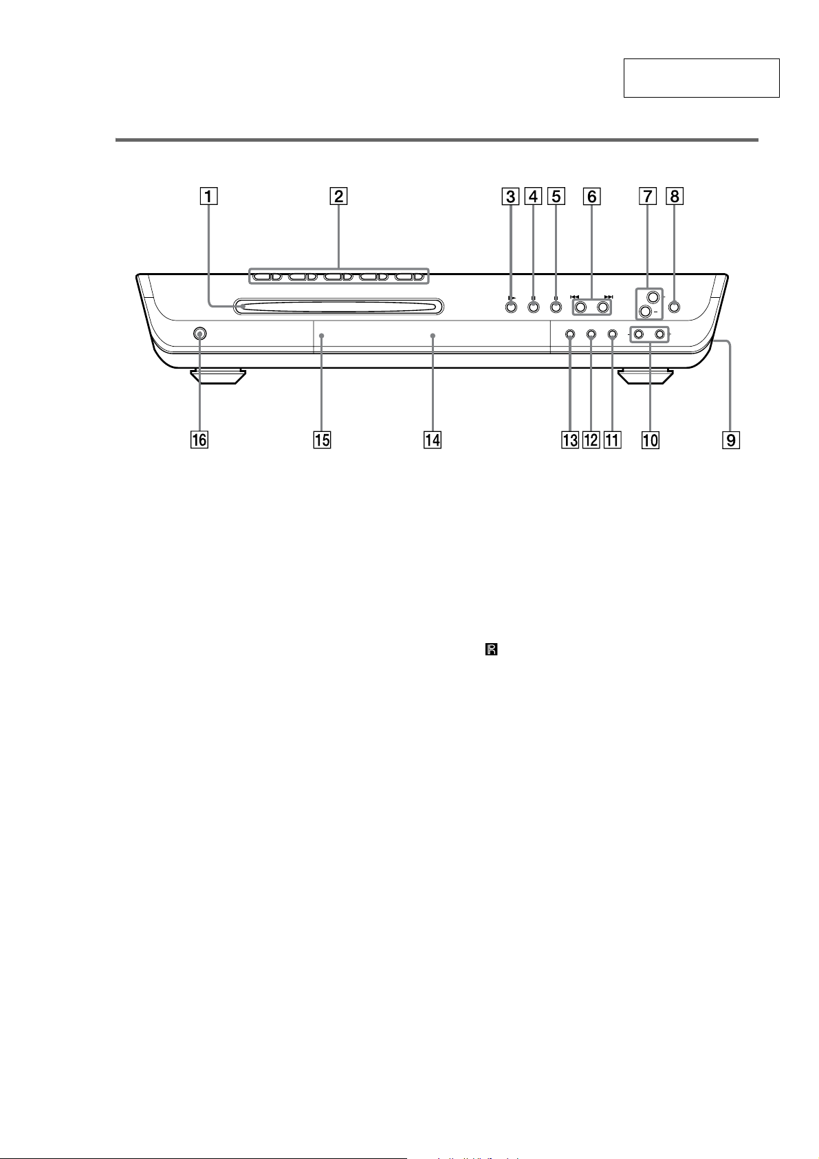
Front Panel
SECTION 2
GENERAL
HCD-FC8/FC9
This section is extracted
from instruction manual.
A Disc slot (24)
B DISC 1-5 A (eject)/indicators (24)
C H (play) (24)
D X (pause) (26)
E x (stop) (26)
F ./>, PREV/NEXT (26, 28, 60, 61)
G VOLUME +/– (24, 71)
H BASS LEVEL (50)
I PHONES jack (on the side of the
system) (24)
J SOUND FIELD –/+ (47, 48, 49)
K DISPLAY (40, 43, 61)
L BAND (60, 61)
M FUNCTION (24, 59, 61)
N Front panel display (82)
O (remote sensor) (13)
P "/1 (power) switch/STANDBY indicator
(24)
7
HCD-FC8/FC9
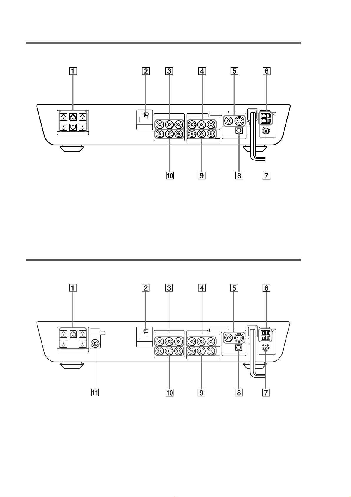
Rear Panel
HCD-FC8
CENTER FRONT LFRONT R
WOOFER SURR LSURR R
SPEAKER
SCAN SELECT
SELECTABLE
INTERLACE
COMPONENT
VIDEO OUT
A SPEAKER jacks (15)
B SCAN SELECT switch (68)
C VIDEO 1 ANALOG OUT jacks (20)
D VIDEO 2 ANALOG IN jacks (20)
E MONITOR O UT ( VIDEO/S VIDEO) jacks
(20)
Rear Panel
HCD-FC9
VIDEO 1
RL
R
VIDEO OUTAUDIO OUT
L
VIDEO INAUDIO IN
MONITOR OUT
VIDEO 2
VIDEO IN
AUDIO IN
RL
PB/CBPR/C
Y
COMPONENT VIDEO OUT
R
VIDEO
OPTICAL
DIGITAL
IN
VIDEO 2
S VIDEO
F AM terminals (18)
G FM 75Ω COAXIAL jack (18)
H VIDEO 2 OPTICAL DIGITAL IN jack (20)
I COMPONENT VIDEO OUT jacks (20)
J VIDEO 1 ANALOG IN jack (20)
AM
FM
75
COAXIAL
CENTER FRONT LFRONT R
SPEAKER
SUB
WOOFER
AUDIO
OUT
SURR LSURR R
A SPEAKER jacks (15)
B SCAN SELECT switch (69)
C VIDEO 1 ANALOG OUT jacks (20)
D VIDEO 2 ANALOG IN jacks (20)
E MONITOR OUT (VIDEO/S VIDEO) jacks
(20)
8
SCAN SELECT
SELECTABLE
INTERLACE
COMPONENT
VIDEO OUT
VIDEO 1
RL
R
VIDEO OUTAUDIO OUT
L
VIDEO INAUDIO IN
MONITOR OUT
VIDEO 2
AUDIO IN
RL
COMPONENT VIDEO OUT
VIDEO IN
PB/CBPR/C
Y
R
VIDEO
OPTICAL
DIGITAL
IN
VIDEO 2
S VIDEO
F AM terminals (18)
G FM 75Ω COAXIAL jack (18)
H VIDEO 2 OPTICAL DIGITAL IN jack (20)
I COMPONENT VIDEO OUT jacks (20)
J VIDEO 1 ANALOG IN jack (20)
K SUB WOOFER AUDIO OUT jack (14)
AM
FM
75
COAXIAL

Remote
Note
This remote contr ol glows in the dark. How ever,
before glowing, the remote must be exposed to light for
awhile.
A DISC SKIP (26)
B
Z (eject) (26)
C DISPLAY (40, 43, 61)
D FUNCTION (24, 59, 61)
E STEREO/MONO (61)
F BAND (60, 61)
G PLAY MODE (33, 34, 35)
H CLEAR (34, 35, 36, 38)
I TV (59)
J AUDIO (45)
K ANGLE (51)
L SUBTITLE (52)
M ./>, PREV/NEXT, PRESET –/+ (26,
28, 60, 61)
N H (play) (24, 28, 34, 35)
O X (pause) (26)
P DVD TOP MENU/ALBUM– (27, 29, 31)
Q C/X/x/c/ENTER (27, 29, 31, 33, 34, 36,
38, 45, 51, 52, 53, 60, 62, 63, 64, 65)
R DVD DISPLAY (29, 31, 33, 36, 38, 43, 44,
45, 51, 52, 53)
S TV CH +/– (58)
T TV VOL +/– (58)
U TV [/1 (on/standby) (58)
V "/1 (standby) (24, 60)
W REPEAT (34, 36)
X NAME (62)
Y SOUND FIELD +/– (47, 48, 49)
Z MEMORY (60)
wj NIGHT MODE (50)
wk Number buttons (27, 28, 34, 38, 51, 53,
55, 58)
wl ENTER (60)
e; m/M// SLOW, TUNING –/+ (32,
37, 60)
ez x (stop) (26, 27, 28, 53)
es MUTING (26)
ed DVD MENU/ALBUM+ (27, 29, 31)
ef VOLUME +/– (61)
eg O RETURN (28, 29, 31, 33, 34, 38, 53,
55, 65)
eh TV/VIDEO (58)
ej BASS LEVEL (50)
ek AMP MENU (63, 64)
el DVD SETUP (55, 65)
HCD-FC8/FC9
9
HCD-FC8/FC9
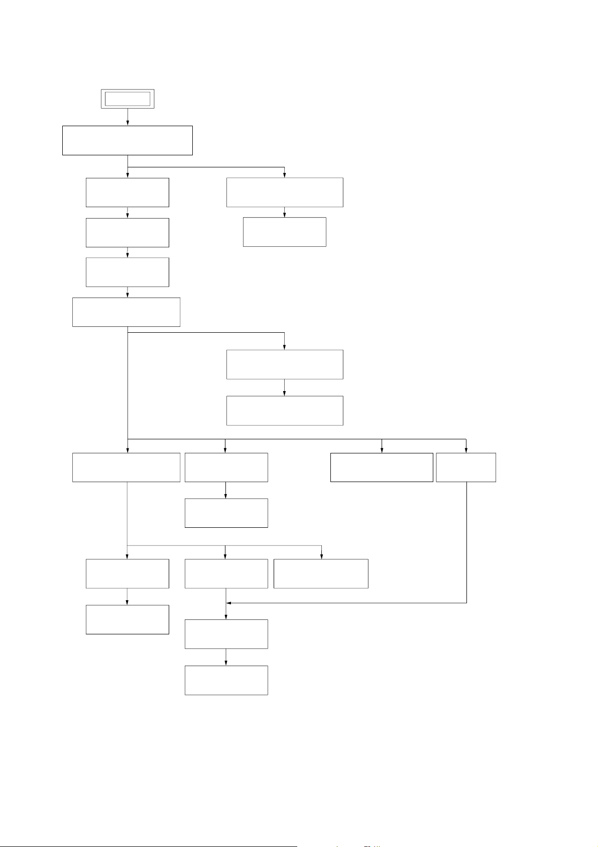
SECTION 3
DISASSEMBLY
• The equipment can be removed using the following procedure.
SET
FRONT PANEL SECTION,
SIDE PANEL (L)/(R) SECTION
POWER BOARD
AMP BOARD
DVD BOARD,
DC FAN
CD MECHANISM DECK
(CDM69-DVBU16)
SW BOARD,
BRACKET (TOP) ASSY
DDCON BOARD, LED BOARD,
FL BOARD
KEY BOARD
SELECTOR BOARD,
VIDEO BOARD, LF BOARD
AUDIO BOARD,
S-VIDEO BOARD
BASE UNIT
(DVBU16)
MOTOR (STOCKER)
ASSY (STOCKER)(M761)
RELAY BOARD
RUBBER ROLLER
(SLIDER) ASSY
TIMING BELT
(FRONT/REAR)
PICK-UP UNIT
(TDP022W)
MOTOR (STOCKER)
ASSY (MODE)(M771)
CAM (GEAR)
SENSOR BOARD
MOTOR (STOCKER)
ASSY (ROLLER)(M781)
10
Note: Follow the disassembly procedure in the numerical order given.
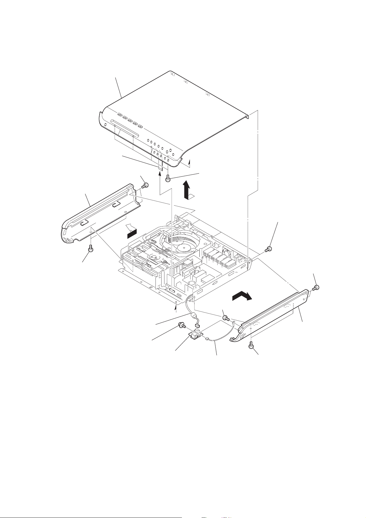
3-1. FRONT PANEL SECTION, SIDE PANEL (L)/(R) SECTION
5
front panel section
wire (flat type)(CN005)
4
8
side panel (L)
6
two screws
(+BVTP 3
×
8)
a
2
four screws
(+BV SUMITITE B3)
3
HCD-FC8/FC9
7
two screws
(+BVTP 3
1
four screws
(+BV SUMITITE B3)
qf
two screws
qh
×
8)
(+BVTP 3
side panel (R)
×
8)
0
screw
9
connector (CN900)
qa
screw
qd
HP board
(+BTP 3
a
qs
connector
(CN901)
×
6)
qg
two screws
(+BVTP 3
×
8)
11

HCD-FC8/FC9
)
3-2. DDCON BOARD, LED BOARD, FL BOARD
qf
panel top (R)
qa
panel top (L)
qg
front (ml) panel
0
three screws
(+BVTP 3
6
power button sub assy
×
8)
5
LED board
4
two screws
(+BVTP 3
qd
three screws
(+BVTP 3
×
8)
qs
band button
×
8)
7
four screws
(+BVTP 3
8
wire (flat type)
9
FL board
2
×
8)
DDCON board
3-3. KEY BOARD
5
four screws
(+BTP 2.6
6
KEY board
9
two screws
(+BVTP 3
×
6)
×
8)
3
two screws
(+BVTP 3
0
slot disc
qa
×
8)
sheet
qd
cover slot
qs
slot disc (inside)
8
three screws
(+BVTP 3
×
8)
3
play button
1
four screws
(+BVTP 3
2
three screws
(+BVTP 3 × 8)
×
8
12
7
disc button sub assy
4
four screws
(+BVTP 3 × 8)
qf
front (al) panel
1
three screws
(+BVTP 3 × 8)
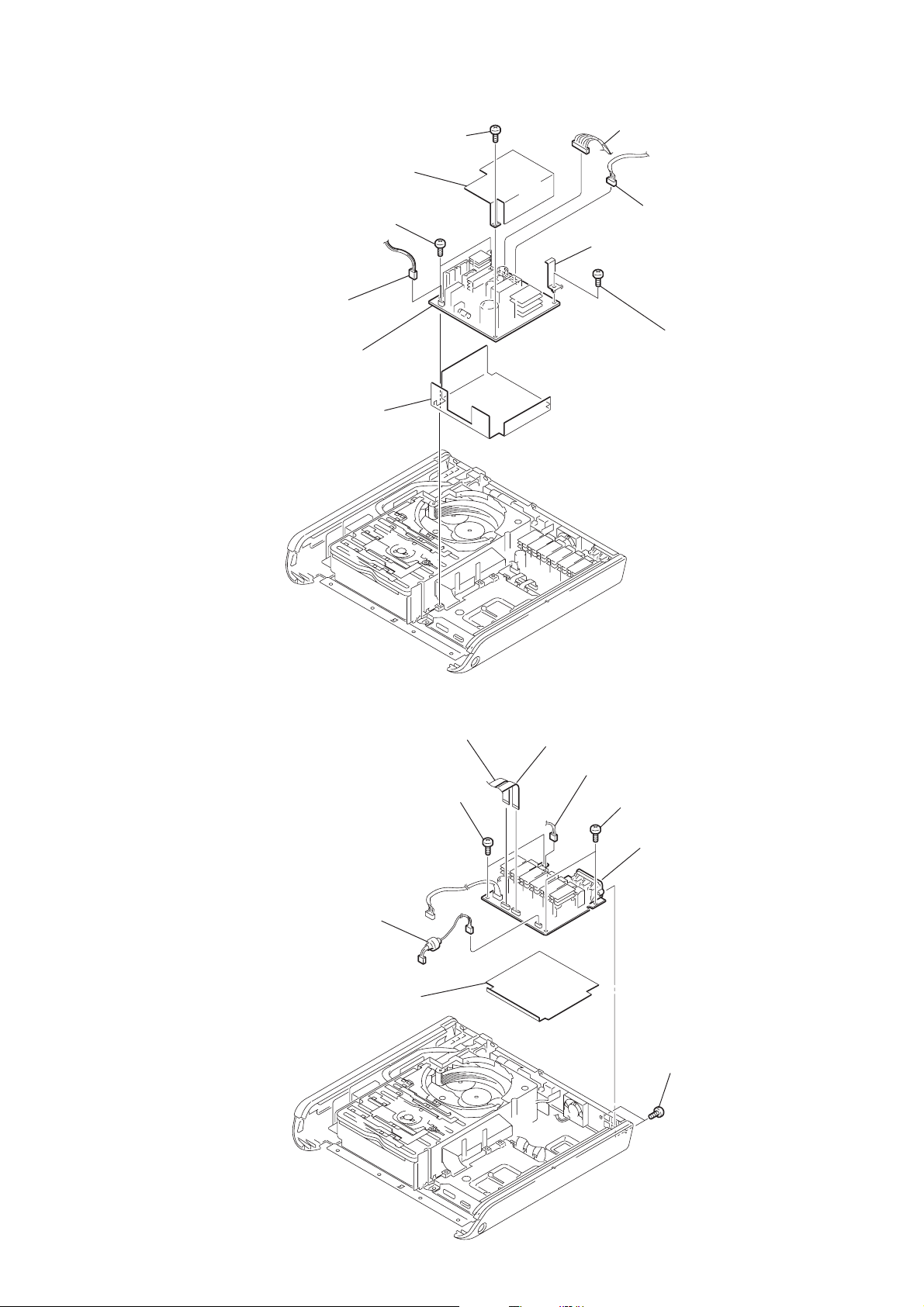
3-4. POWER BOARD
)
3
connector (CN902)
2
4
two screws
(+BVTP 3
q;
POWER board
9
power sheet
1
screw
(+BVTP 3
power sheet
×
8)
HCD-FC8/FC9
8
×
8)
connector (CN903)
7
6
sheet
connector (CN904
5
screw
(+BVTP 3
×
8)
3-5. AMP BOARD
5
connector (CNP301)
8
6
two screws
(+BVTP 3
amp sheet
2
wire (flat type)
(CN304)
×
8)
3
wire (flat type)
(CN303)
4
connector (CN302)
7
two screws
(+BVTP 3
9
AMP board
1
two screws
(+BVTP 3
×
8)
×
8)
13

HCD-FC8/FC9
)
3-6. DVD BOARD, DC FAN
6
power bracket
7
wire (flat type)(CN002)
qh
sheet
3
two screws
(+BVTP 3
4
sheet
qd
sheet
qf
sheet
qg
sheet
5
×
8)
two screws
(+BVTP 3
×
8)
qj
8
wire (flat type)(CN001)
DVD board
qa
wire (flat type)(CN003)
qs
0
connector (CN008
9
wire (flat type)(CN004)
wire (flat type)(CN401)
2
DC FAN
1
(+BVTP 3
two screws
×
8)
14
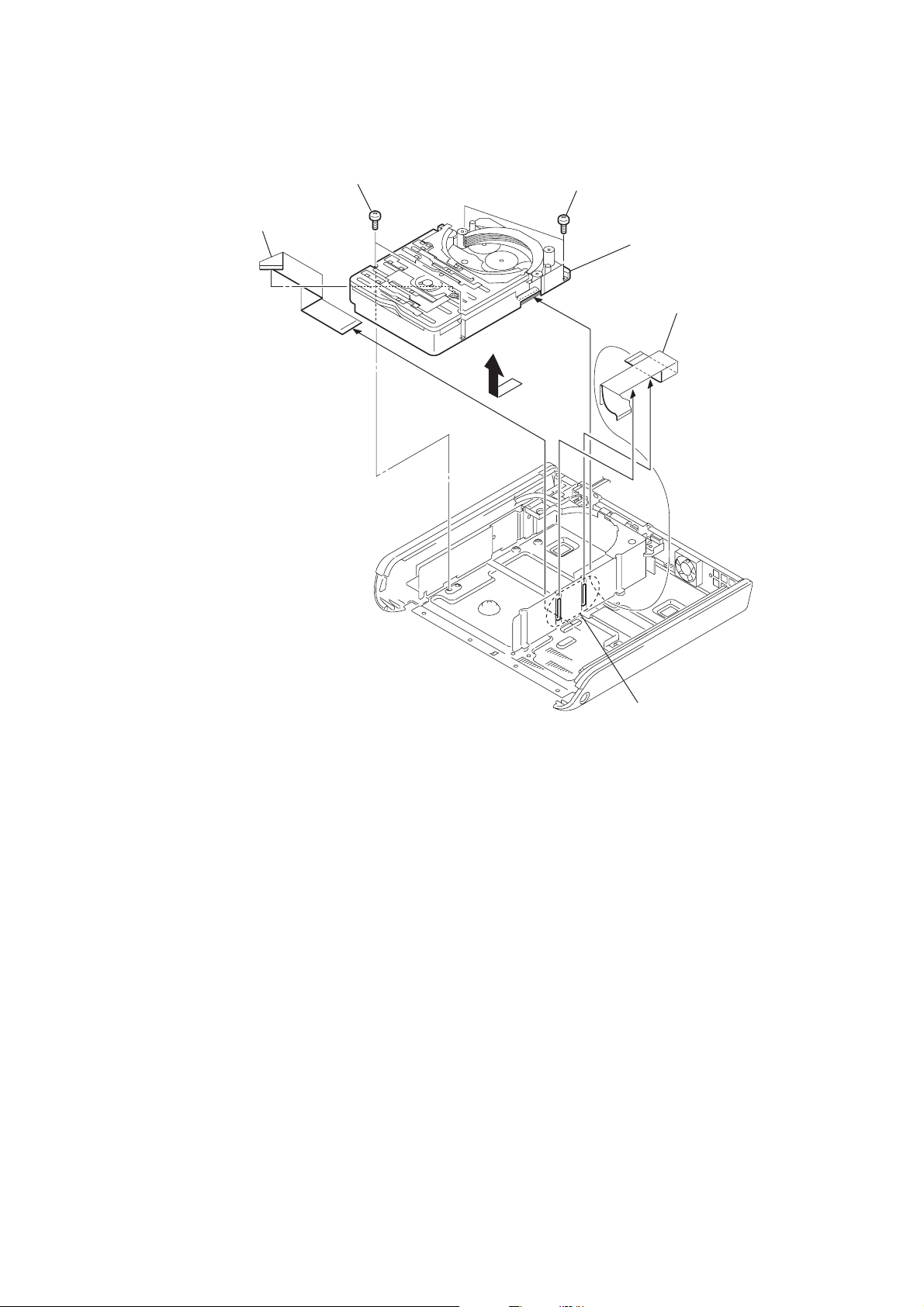
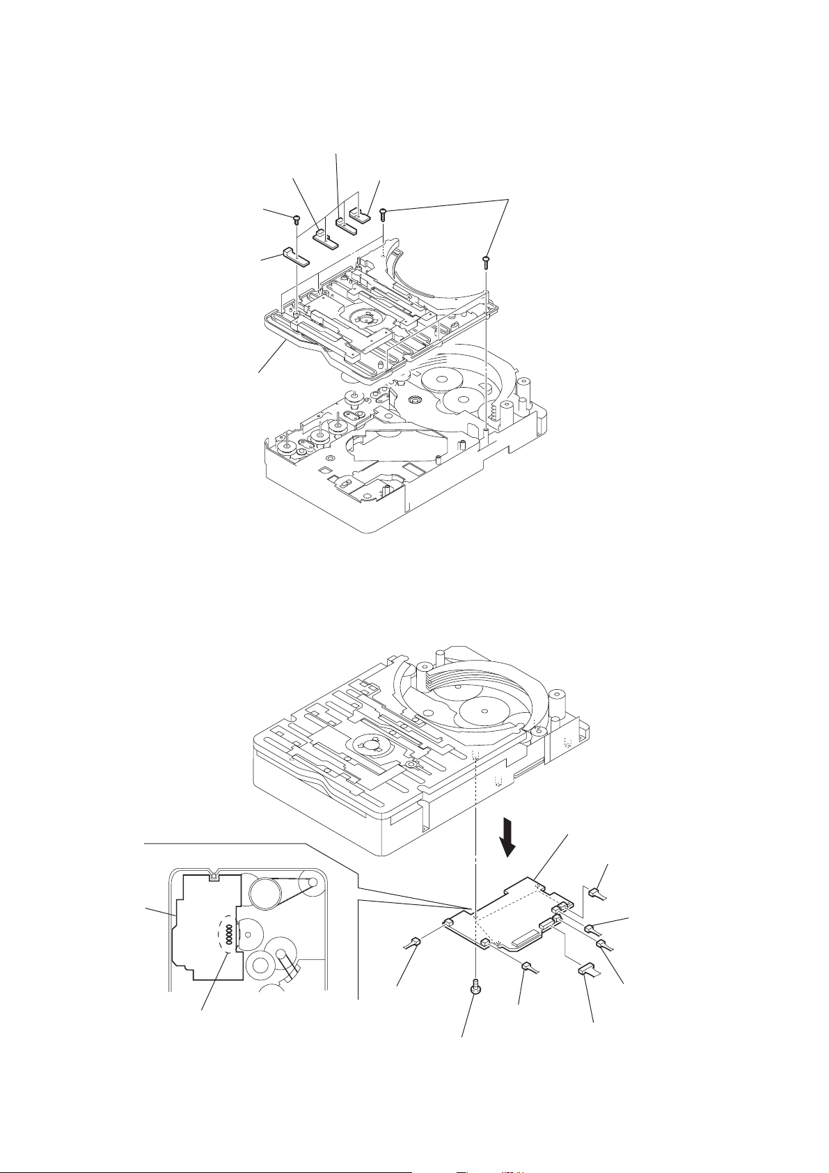
3-7. CD MECHANISM DECK (CDM69-DVBU16)
k
1
6
wire (flat type)
(CN002)
two screws (BVTP 3
×
8)
3
2
two screws (BVTP 3
×
8)
7
CD mechanism dec
(CDM69-DVBU16)
5
wire (flat type)
(CN701)
HCD-FC8/FC9
4
two claws
15
HCD-FC8/FC9
)
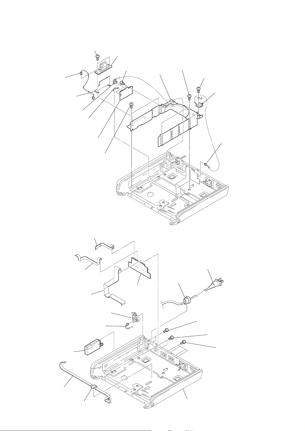
3-8. SELECTOR BOARD, VIDEO BOARD, LF BOARD
qs
two screws (+BVTP 3 × 8)
qd
LF board
9
two screws
(+BVTP 3
qa
connector (CN901)
qf
sheet
7
connector (CN210)
8
wire (flat type)(CN203)
0
VIDEO board
4
two screws
(+BTP 3
×
6)
×
8)
6
md cover
5
two screws
(+BTP 3
×
6)
1
screw
(+BVTP 3
3
SELECTOR board
×
8)
2
connector (CN205
3-9. AUDIO BOARD, S-VIDEO BOARD
2
wire (flat type)(CN208)
3
wire (flat type)(CN201)
4
wire (flat type)(CN202)
8
S-VIDEO board
7
connector (CN211)
0
tuner unit
5
AUDIO board
qa
cord stopper
qs
power cord
9
two screws
(+BTP 3
×
6)
6
two screws
(+BVTP 3
1
four screws
(+BVTP 3
×
8)
×
8)
16
qd
wire (flat type)
qf
ferrite core
chassis

)
3-10. BASE UNIT (DVBU16)
)
2
3
HCD-FC8/FC9
boss
3-11. PICK-UP UNIT (TDP022W)
7
insulator
0
pick-up unit (TDP022W)
3
step screw (M)
5
boss
1
step screw (M)
6
base unit
(DVBU16)
4
4
boss
1
screw
(PTPWHM2.6
2
step screw (M
8
insulator
9
insulator
5
connector
(CN003)
6
flexible board
17
HCD-FC8/FC9
r
3-12. SW BOARD, BRACKET (TOP) ASSY
3
SW board (2)
1
four
screws
(BTP2.6
×
6)
2
SW board (1)
7
bracket (top) assy
4
SW board (3)
5
SW board (4)
6
six screws
(BVTP2.6
×
8)
3-13. RELAY BOARD
RELAY board
1
– bottom view –
Remove five solders.
4
connector
(CN703)
2
four screws
(BVTP2.6
5
connector
(CN702)
×
8)
3
0
RELAY board
9
6
connector
(CN710)
connector
(CN708)
8
connecto
(CN707)
7
connector
(CN706)
18
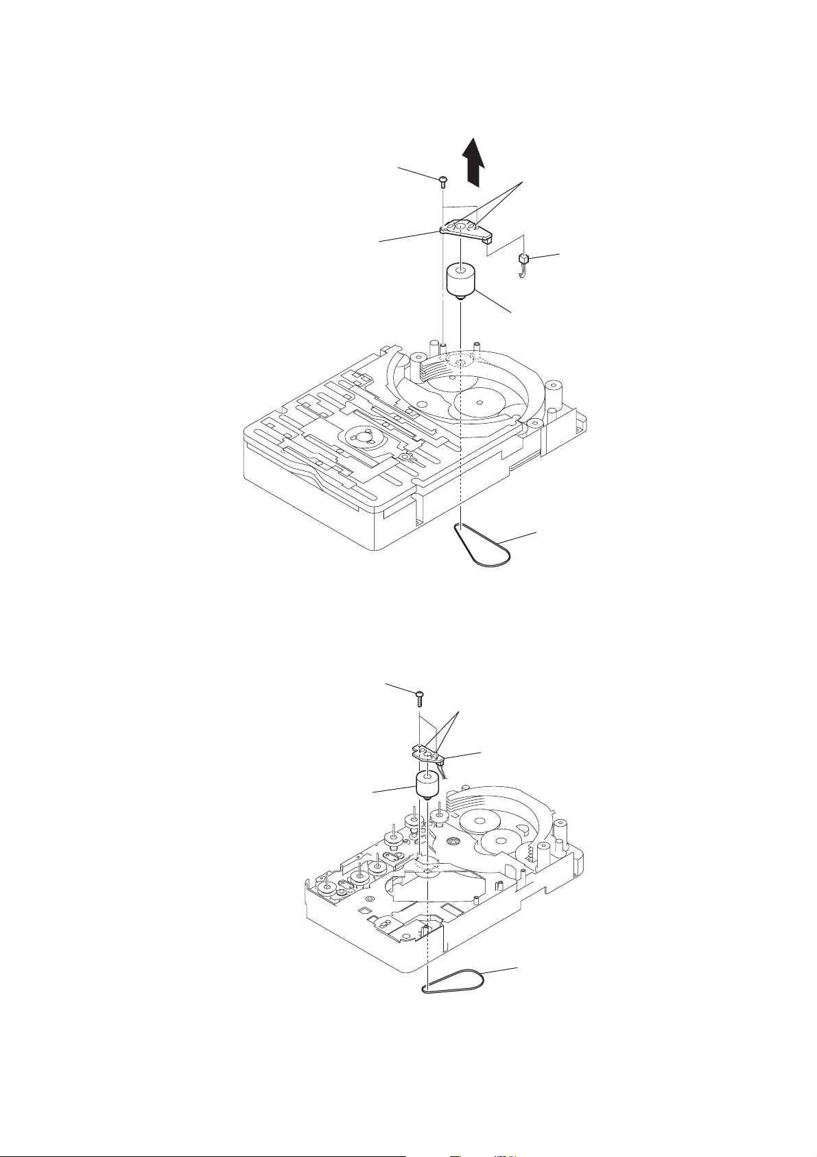
3-14. MOTOR (STOCKER) ASSY (STOCKER)(M761)
d
HCD-FC8/FC9
3
two screws
(BVTP2.6
6
STOCKER MOTOR board
×
4
8)
2
Remove two solders
5
connector
(CN761)
7
motor (stocker) assy
(stocker) (M761)
1
belt (stocker)
3-15. MOTOR (STOCKER) ASSY (ROLLER)(M781)
3
two screws
(BVTP2.6
5
motor (stocker) assy
(roller) (M781)
×
8)
2
Remove two solders.
4
ROLLER MOTOR boar
1
belt (roller)
19
HCD-FC8/FC9
y
)
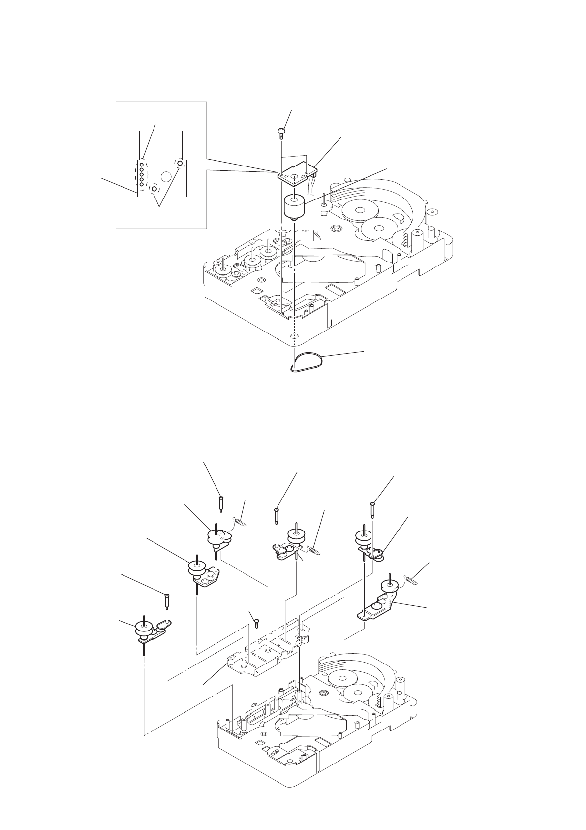
3-16. MOTOR (STOCKER) ASSY (MODE)(M771)
1
Remove five solders
of rotary encoder.
MODE MOTOR
board
2
Remove two solders
of motor (M771)
3
two screws
(BVTP2.6
×
8)
4
MODE MOTOR board
6
motor (stocker) ass
(mode) (M771)
3-17. RUBBER ROLLER (SLIDER) ASSY
8
step screw
0
rubber roller
(slider 4) assy
qa
rubber roller
(slider 2) assy
qs
step screw
qf
qd
rubber roller
(slider 1) assy
9
screw
(BVTP2.6
tension
spring
(slider 2)
×
8)
5
step screw
6
tension spring
(base slider 5)
7
rubber roller
(slider 1) assy
5
belt (mode)
1
step screw
2
rubber roller
(slider S) assy
3
4
tension spring
(base slider 5
rubber roller
(slider 5) assy
20
qg
sub chassis
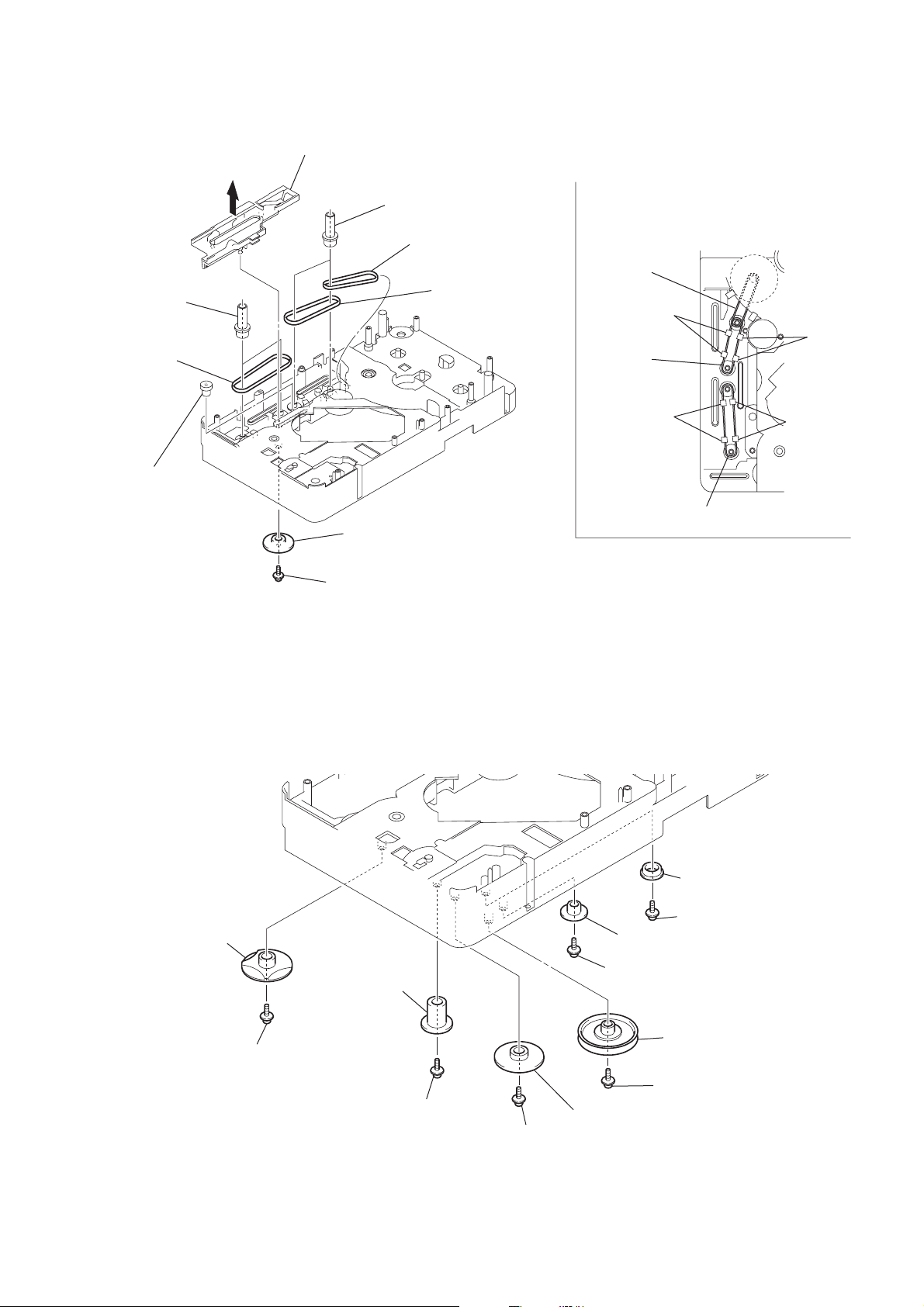
3-18. TIMING BELT (FRONT/REAR)
s
3
slider (mode cam) assy
5
two gears
(center)
6
timing belt
(front)
7
two gears (center)
8
timing belt (rear)
9
timing belt (rear)
HCD-FC8/FC9
When install three timing belts,
its pass under each claws.
timing belt
(rear)
two claws
timing belt
(rear)
two claw
4
gear
(timing)
3-19. CAM (GEAR)
2
gear (mode cam)
1
screw
(PTPWH2.6
×
two claws
timing belt (front)
8)
two claws
qs
cam (gear)
qa
screw
(PTPWH2.6 × 8)
0
gear
(mode 2)
9
screw
(PTPWH2.6 × 8)
7
screw
(PTPWH2.6 × 8)
4
3
8
gear (mode 3)
6
gear (mode 4)
5
screw
gear
(mode 5)
screw
(PTPWH2.6 × 8)
(PTPWH2.6 × 8)
2
pulley
(mode deceleration)
1
screw
(PTPWH2.6 × 8)
21
HCD-FC8/FC9
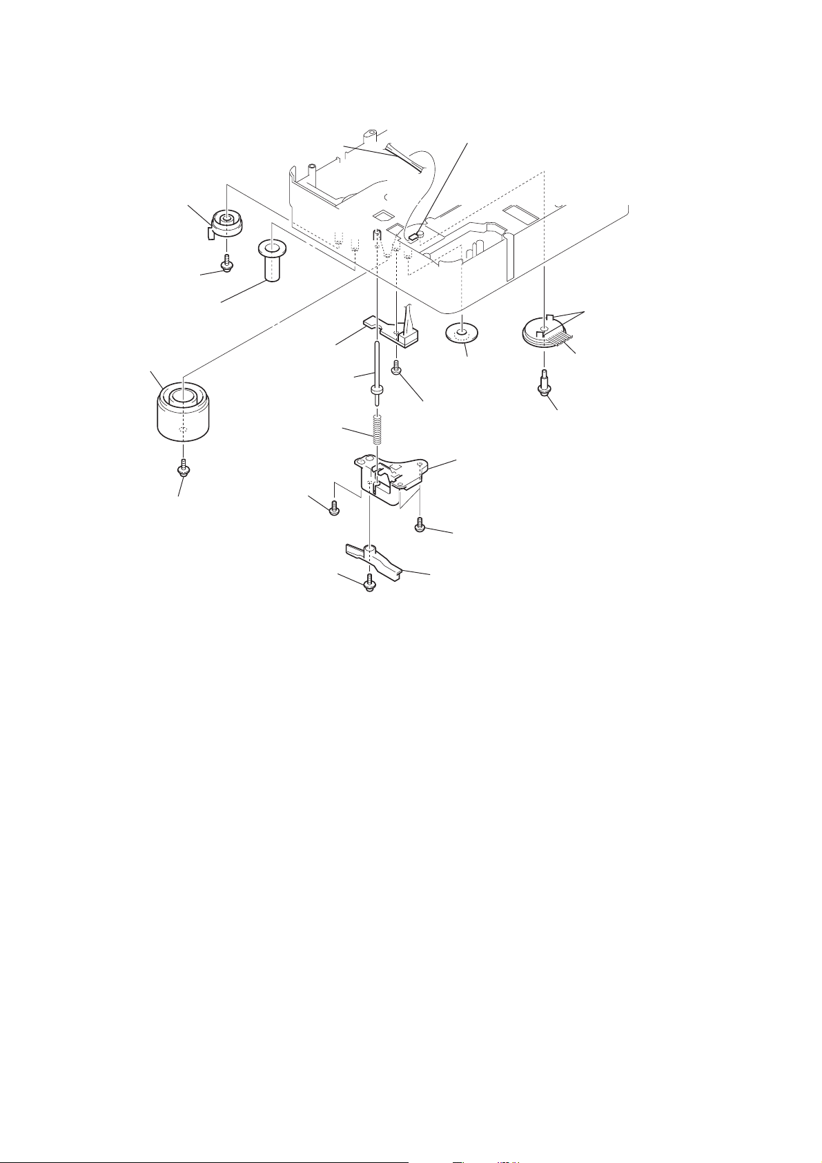
3-20. SENSOR BOARD
9
cam
(eject lock)
8
screw
(PTPWH2.6
qs
gear
(eject lock)
qa
cam
(BU U/D)
0
screw
(PTPWH2.6
qj
qk
harness
×
8)
w;
SENSOR board
7
shaft
6
compression spring
(shutter)
3
screw
(BVTP2.6
×
8)
1
screw
(PTPWH2.6
×
8)
(shutter)
×
8)
ql
screw
(BVTP2.6
2
claw
qd
gear
(mode 1)
×
8)
5
base (shutter) block
4
two screws
(BVTP2.6
lever shutter (A)
qg
two claws
qh
rotary encoder
(S771)
qf
screw
(PTPWH2.6
×
8)
×
8)
22
SECTION 4
ASSEMBLY
• This set can be assembled in the order shown below.
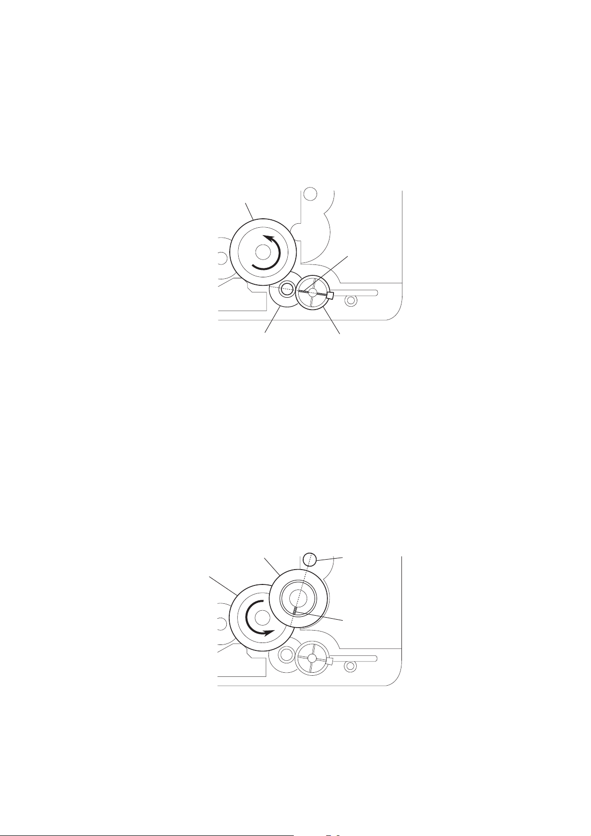
4-1. HOW TO INSTALL THE CAM (EJECT LOCK)
1
Rotate the cam (BU U/D) fully in the direction of arrow.
2
Engage the gear (eject lock) and the gear of the cam (eject lock)
aligning the mark with the center of the gear (eject lock).
cam (BU U/D)
HCD-FC8/FC9
mark
gear (eject lock)
4-2. HOW TO INSTALL THE CAM (GEAR)
1
Check that the cam (BU U/D) can not be rotated in the direction of arrow.
2
Align the mark on the cam (gear) with the boss as shown in the figure
and install the cam (gear).
cam (gear)
cam (BU U/D)
cam (eject lock)
– bottom view • front –
boss
mark
– bottom view • front –
23

HCD-FC8/FC9
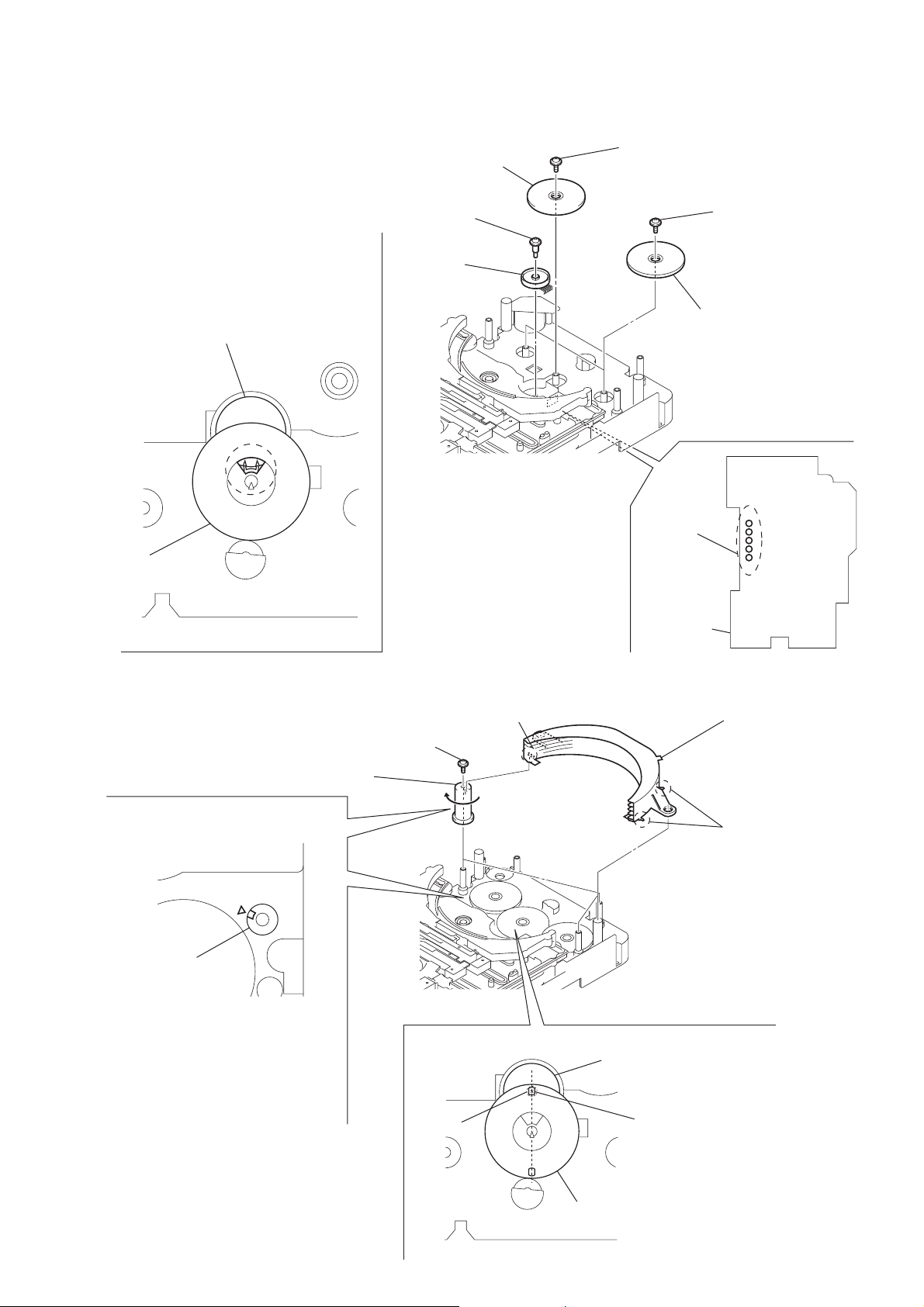
4-3. HOW TO INSTALL THE GEAR (MODE 2)
1
Align the mark on the rotary encoder (S771) with the projection of the assy.
2
Check that the cam (BU U/D) can not be rotated in the direction of arrow.
3
Install the gear (mode 2).
rotary encoder
(S771)
gear
(mode 2)
cam (BU U/D)
mark projection chassis
– bottom view • front –
4-4. HOW TO INSTALL THE GEAR (MODE CAM)
1
Slide the shaft in the direction of arrow.
2
Align mark A on the gear (mode cam) with mark B on the slider (mode cam) assy,
then install the gear (mode cam).
3
Check that mark C on the gear (mode cam) is in alignment with mark D on the cam (gear).
mark
A
gear (mode cam)
shaft
slider (mode cam) assy
24
cam (gear)
mark
D
– bottom view • front –
mark
mark
B
C
HCD-FC8/FC9
r
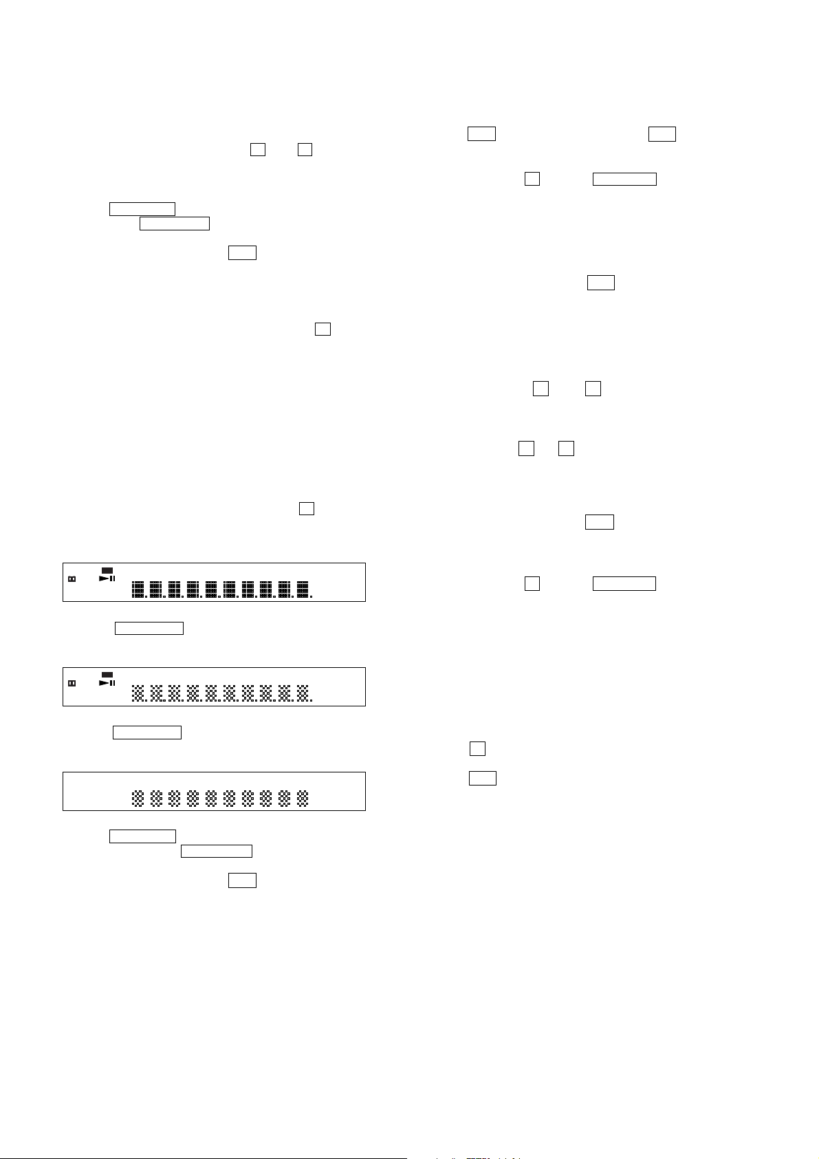
4-5. HOW TO INSTALL THE ROTARY ENCODER (S702), GEAR (STOCKER COMMUNICATION)
4
Engage the rotary encoder (S702)
and the gear (stocker communication)
as shown below in the figure.
rotary encoder
(S702)
gear
(stocker communication)
3
screw
(PWH2
×
6)
1
rotary encoder
(S702)
5
screw
(PTPWH2.6
×
8)
7
two screws
(PTPWH2.6
6
two gears
(stocker communication)
×
8)
gear
(stocker
communication)
– rear –
4-6. HOW TO INSTALL THE STOCKER ASSY
3
three screws
cam
(stocker U/D)
2
three cams
(stocker U/D)
(PTPWH2.6
×
2
five
solders
RELAY board
shaft
8)
Install the stocker assy
fitting three shafts into the
each groove of cam (stocke
U/D) then fix by rotating
the cams in the direction
of arrow.
shaft
To install three cams
(stocker U/D), align each groove
of the cam (stocker U/D)
with each
chassis as shown in the figure.
f
mark on the
screw
– rear –
rotary encoder
(S702)
hole
1
Position the hole on the gear
(stocker communication) on the
screw of the rotary encoder (S702).
gear
(stocker communication)
25
HCD-FC8/FC9
SECTION 5
TEST MODE
[Version Display Mode]
*The software version is displayed.
Procedure:
1. Press three buttons of [FUNCTION], x and A (DISC 1)
simultaneously for two seconds.
2. The message “VERSION” is displayed. The version display
mode is activated.
3. Press the NEXT > button. “IF ***” is displayed.
4. Each time the NEXT > button is pressed, the display
changes in the order of DVD, AREA, VERSION and IF.
5. To exit from this mode, press the ?/1 button.
[Key T est Mode]
* Button check
Procedure:
1. Press three buttons of [DISPLAY], [FUNCTION] and A (DISC
2) simultaneously.
2. The message “KEY NUM 0” is displayed and “0” blinks.
3. Each time a button is pressed, “KEY NUM 0” value increases.
However, once a button is pressed, it is no longer taken into
account.
4. When all buttons are pressed, “KEY NUM 24” appears and
the number blinking is stopped.
5. To exit from this mode, disconnect the power cord.
[Display T est Mode]
Procedure:
1. Press three buttons of [BAND], [DISPLAY] and A (DISC 3)
simultaneously.
2. All segments and LEDs are turned on.
dts
SACD MULTI ST NIGHT ALBMTITLESLEEP TRK CHAP INDEX H TUNED M MONO S
DIGITAL
D
D
DOLBY PLII FMAM
PCMMP3ALL1DISC S
3. When the NEXT > button is pressed, all LEDs are still
turned on and the display will light up as follows.
dts
SACD MULTI ST NIGHT ALBMTITLESLEEP TRK CHAP INDEX H TUNED M MONO S
DIGITAL
D
D
DOLBY PLII FMAM
PCMMP3ALL1DISC S
4. Press the NEXT > button, all LEDs are turned off and
confirm the display.
kHz BASS SHUF
MHz PBC PROG
NTSC REP1
kHz BASS SHUF
MHz PBC PROG
NTSC REP1
[OSD Test Mode]
Procedure:
1. Press the ?/1 button on the main unit or the ?/1 button on
the remote commander to turn the set on.
2. Set the FUNCTION to DVD.
3. Press three buttons of A (DISC 1) , . PREV and [VOLUME
+] simultaneously.
4. The message “SERVICE IN” is displayed on the display. The
Test Mode Menu is displayed on the TV screen.
5. To execute each function, select the number on the remote
commander.
6. See the following section for explanation in detail.
7. To exit from this mode, press the ?/1 button.
[Disc Slot Lock]
The disc slot lock function for the antitheft of an demonstration
disc in the store is equipped.
Setting Procedure:
1. Turn the set on.
2. Press two buttons of x and A simultaneously for five
seconds.
3. The message “LOCKED” is displayed and the slot is locked.
Releasing Procedure:
1. Press two buttons of x and A simultaneously for fi ve seconds
again.
2. The message “UNLOCKED” is displayed and the slot is
unlocked.
Note : When “LOCKED” is displayed, the slot lock is not released
by turning power on/off with the ?/1 button.
[Repeat Limit Release Mode]
Procedure:
1. Press three buttons of A (DISC 1) , . PREV and [VOLUME
-] simultaneously.
2. Repeat limit is released.
[CDM Ship Mode]
*This mode moves the optical pick-up to the position durable to
vibration. Use this mode when returning the set to the customer
after repair.
Procedure:
1. Turn the set on.
2. Set the function to DVD.
3. Press the x button for five seconds.
4. The message “MECHA LOCK” is displayed.
5. Press the ?/1 button to turn off. The CDM ship mode is set.
5. Press the NEXT > button, all segments are turned off.
6. Every pressing of the NEXT > button turns on each
segments in the same order.
7. To exit from this mode, press the ?/1 button.
26

HCD-FC8/FC9
[GENERAL DESCRIPTION]
The T est Mode allows you to mak e diagnosis and adjustment easily
using the remote commander and monitor TV. The instructions,
diagnostic results, etc. are given on the on-screen display (OSD).
[TEST DISC LIST]
Use the following test disc on test mode.
TDV-520CSO (DVD-SL): PART No. J-2501-236-A
LUV-P01 (CD): PART No. 4-999-032-01
TDV-540C (DVD-DL): PART No. J-2501-235-A
Note: Do not use exiting test disc for DVD.
[STARTING TEST MODE]
1. Press the @/1 button to turn the power on, and set the function
to DVD.
2. Press three buttons of Z (DISC1), . PREV and
[VOLUME +] simultaneously to enter the test mode.
3. It displays “SERVICE IN” on the fluorescent indicator tube,
and displays the Test Mode Menu on the monitor screen as
follows. (At the bottom of the menu screen, the model name
and revision number are displayed)
Test Mode Menu
0. Syscon Diagnosis
1. Drive Auto Adjustment
2. Drive Manual Operation
3. Mecha Aging
4. Emergency History
5. Mecha Error History
6. Version Information
7. Video Level Adjustment
Exit: POWER Key
Model :DAV-xx xx
Revision :x.xx
4. T o execute eac h function, select the desired menu and press its
number on the remote commander (RM-SP900).
5. To release from test mode, press the
power off.
@/1 button and turn the
[OPERATING TEST MODE]
0. SYSCON DIAGNOSIS
The same contents as board detail check by serial interface can be
checked from the remote commander operation.
On the Test Mode Menu screen, press [10/0] key on the remote
commander, and the following Check Menu will be displayed.
### Syscon Diagnosis ###
Check Menu
0. Quit
1. All
2. Version
3. EEPROM
4. GPIO
5. SD Bus
6. Video
0-1. All (All items continuous check)
This menu checks all diagnostic items continuously. Normally, all
items are checked successively one after another automatically
unless an error is found, but at a certain item that requires judgment
through a visual check to the result, the following screen is displayed
for the key entry.
• Example display
### Syscon Diagnosis ###
Diag All Check
No.2 Version
2-3. ROM Check Sum
Check Sum = 5498
Press NEXT Key to Continue
Press PREV Key to Repeat
For the ROM Check, the check sum calculated by the Syscon is
output, and therefore you must compare it with the specified value
for confirmation.
Following the message, press the [NEXT ] button to go to the
next item, or press the [ PREV] button to repeat the same
operation again.
To quit the diagnosis and return to Check Menu screen, press the
.
>
[RETURN] key on the remote commander to display Check Menu.
• Error occurred
If an error occurred, the diagnosis is suspended and error is displayed.
Press the
diagnosis, or press the [ PREV] button to repeat the same check
where an error occurred, or press the [NEXT ] button to continue
the check from the item next to faulty item.
General Description of Checking Method
Selecting 2 and subsequent items calls the submenu screen of each
item. And selecting 2 and subsequent items executes respective
menus and outputs the results.
For the contents of each submenu, see “Check Items List” as below .
Check Items List:
[RETURN] key on the remote commander to quit the
.
>
0-2. Version
0-2-1. All
0-2-2. Revision
0-2-3. ROM Check Sum
0-2-4. Model T ype
0-2-5. Region
0-3. EEPROM Check
0-3-1. Sampling Check
0-3-2. Detail Check
0-4. GP I/O Check
0-5. SD Bus Check
0-6. Video Check
0-0. Quit
Quit the Syscon Diagnosis and return to the Test Mode Menu.
0-2. Version
0-2-2. Revision
The revision number of ROM (IC205) that the program for
the DVD system processor (IC206) is stored.
0-2-3. ROM Check Sum
Check sum is calculated. (4 digits hexadecimal number)
27

HCD-FC8/FC9
0-2-4. Model Type
Model name is displayed.
0-2-5. Region
Model destination code is displayed. (2 digits number)
0-3. EEPROM Check
0-3-1. Sampling Check
EEPROM check at every 64 words.
It compares read data with write data of each address. When
there are discrepancies between two data, it displays error.
0-3-2. Detail Check
EEPROM check at every 1 word.
It compares read data with write data of each address. When
there are discrepancies between two data, it displays error.
0-4. GP I/O Check
Pull up/down setting check of the DVD system processor (IC206)
pin 150, 151 and 154 (for clock setting port).
0-5. SD Bus Check
SD bus data check between DVD decoder (IC701) and D-RAM
(IC706).
0-6. Video Check
Output the color bars for video level adjustment.
1. DRIVE AUTO ADJUSTMENT
On the Test Mode Menu screen, press the [1] key on the remote
commander, and the Adjustment Menu will be displayed.
## Drive Auto Adjustment ##
Adjustment Menu
0. ALL
1. DVD-SL
2. CD
3. DVD-DL
1-1. DVD-SL (single layer)
Press the 1 key on the remote commander and insert a D VD single
layer disc following the message. Then the adjustment will be made
through the steps below, then adjusted values will be written to the
EEPROM.
DVD Single Layer Disc Adjustment Steps:
1. Sled tilt reset
2. Disc check memory SL
3. Wait 300 msec
4. Set disc type SL
5. LD on
6. Spindle start
7. Wait 1 sec
8. Focus servo on 0
9. Auto track offset adjust
10. CLVA on
11. Wait 500 msec
12. Tracking on
13. Wait 1 sec
14. Sled on
15. Check CLV on
16. Auto LFO adjust
17. Auto focus offset adjust
18. Auto tilt position adjust
19. Auto focus gain adjust
20. Auto focus offset adjust
21. EQ boost adjust
22. Auto loop filter offset adjust
23. Auto track gain adjust
Search Check
24. 32 track jump forward
25. 32 track jump reverse
26. 500 track jump forward
27. 500 track jump reverse
28.All servo stop
29.EEP copy loop filter offset
1-2. CD
Press the
following the message. Then the adjustment will be made through
the steps below , then adjusted values will be written to the EEPR OM.
[2] key on the remote commander and insert a CD disc
Exit: RETURN
Normally,
DVD (dual layer) in this order . But, individual items can be adjusted
for the case where adjustment is suspended due to an error. In this
mode, the adjustment can be made easily through the operation
following the message displayed on the screen.
The disc used for adjustment must be the one specified for
adjustment.
1-0. ALL
Press the [10/0] key on the remote commander, and the servo set
data in EEPROM will be initialized. T hen, 1. DVD-SL disc, 2. CD
disc and 3. DVD-DL disc are adjusted in this order.
Each time one disc was adjusted, it is ejected. Replace it with the
specified disc following the message. You can f inish the adjustment
by pressing the [RETURN] button on the remote commander.
Note: During adjustment of each disc, the measurement for disc type judg-
[10/0] is selected to adjust DVD (single layer), CD and
ment is made. As automatic adjustment does not judge the disc
type unlike conventional models, take care not to insert wrong type
discs. Also, do not give a shock during adjustment.
28
CD Adjustment Steps
1. Sled tilt rest
2. Disc check memory CD
3. Wait 500 msec
4. Set disc type CD
5. LD on
6. Spindle start
7. Wait 500 msec
8. Focus servo on 0
9. Auto track offset adjust
10. CLVA on
11. Wait 500 msec
12. Tracking on
13. (TC display start)
14. Wait 1 sec
15. Jitter display start
16. Sled ON
17. Check CLV on
18. Auto loop filter offset adjust
19. Auto focus offset adjust
20. Auto focus gain adjust
21. Auto focus offset adjust
22. EQ boost adjust
23. Auto LFO Adjust

HCD-FC8/FC9
24. Auto track gain adjust
Search Check
25. 32Tj forward
26. 32Tj reverse
27. 500Tj forward
28. 500Tj reverse
29. All servo stop
1-3. DVD-DL (dual layer)
Press the [3] key on the remote commander and insert a D VD dual
layer disc following the message. Then the adjustment will be made
through the steps below , then adjusted values will be written to the
EEPROM.
DVD Dual Layer Disc Adjustment Steps:
1. Sled tilt reset
2. Disc check memory DL
3. Wait 500 msec
4. Set disc type DL
5. LD on
6. Spindle start
7. Wait 1 sec
Layer 1 Adjust
8. Focus servo on 0
9. Auto track offset adjust
10. CLVA on
11. Wait 500 msec
12. Tracking on
13. Wait 500 msec
14. Sled on
15. Check CLV lock
16. Auto loop filter offset adjust, Auto focus adjust
17. Auto focus gain adjust
18. Auto focus offset adjust
19. EQ boost adjust
20. Auto loop filter offset adjust
21. Auto Track Gain Adjust
Search Check
22. 32 track jump forward
23. 32 track jump reverse
24. 500 track jump forward
25. 500 track jump reverse
Layer 0 Adjust
26. Focus jump (L1 t L0)
27. Auto track offset adjust L0
28. CLVA on
29. Wait 500 msec
30. Tracking on
31. Wait 500 msec
32. Sled on
33. Check CLV lock
34. Auto focus filter offset adjust
35. Auto Focus Adjust
36. Auto focus gain adjust
37. Auto focus offset adjust
38. EQ boost adjust
39. Auto Loop Filter Offset
40. Auto track gain adjust
Search Check
41. 32 track jump forward
42. 32 track jump reverse
43. 500 track jump forward
44. 500 track jump reverse
Layer Jump Check
45. Layer jump (L0 ? L1)
46. Layer jump (L1 ? L0)
47. All servo stop
2. DRIVE MANUAL OPERATION
Note: This mode is used for design, and not used in service fundamen-
tally.
On the Test Mode Menu screen, press the [2] key on the remote
commander, and the Operation Menu will be displayed. For the
manual operation, each servo on/off control and adjustment can be
executed manually.
## Drive Manual Operation ##
Operation Menu
1. Disc Type
2. Servo Control
3. Track/Layer Jump
4. Non EEPROM Write Adjust
5. EEPROM Write Adjust
6. Memory Check
7. Disc Check Memory
8. Error Rate Display
9. SACD Water Mark
Exit: RETURN
In using the manual operation menu, take care of the following
points. These commands do not provide protection, thus requiring
correct operation. The sector address or time code field is displayed
when a disc is loaded.
Note:
1. Set correctly the disc type to be used on the Disc Type scr een.
2. In case of an alarm, immediately press the x button to stop the
servo operation, and press the @/1 button to turn the power off.
Basic operation:
(controllable from front panel or remote commander)
@/1 :Power OFF (release the Test Mode)
x : Servo stop
A (DISC1 to 5) : Stop and eject/Loading
[RETURN] : Return to Operation Menu or Test
Mode Menu
[ PREV], [NEXT ] :Transition between sub modes of menu
>.
[1] to [9], [10/0] : Selection of menu items
Cursor o/
O
: Increase/Decrease in manually
adjusted value
29

HCD-FC8/FC9
2-1. Disc Type
Disc Type
Disc Type Select
1. Disc Type Auto Check
2. Set Disc Type DVD
3. Set Disc Type CD
4. Set Disc Type Hybrid
Exit: RETURN
2-1-1. Disc Type Auto Check
1) Press the [1] key on the remote commander to display the Disc
Type Auto Check screen.
2) Insert a disc and press the [ENTER] key on the remote
commander.
3) It judges the type of inserted disc automatically and displays
the disc type and so on as below.
Disc Type Auto Check
Disc Type xx
Layer xx
Mirr Time xx
Mirr Count xx
FZC Count xx
PI Reference xx
PI Peak xx
2-1-3. Disc Type CD
It sets up so that it may judge as a disc type of specification of the
disc with which the set was inserted.
[1]: CD disc (normal speed, 12 cm)
[2]: CD disc (double speed, 12 cm)
[3]: CD disc (normal speed, 8 cm)
[4]: CD disc (double speed, 8 cm)
[5]: CD-RW disc (normal speed, 12 cm)
[6]: CD-RW disc (double speed, 12 cm)
[7]: CD-RW disc (normal speed, 8 cm)
[8]: CD-RW disc (double speed, 8 cm)
2-1-4. Disc Type Hybrid
It sets up so that it may judge as a disc type of specification of the
disc with which the set was inserted.
[1]: SACD Hybrid disc (SACD layer, 12 cm)
[2]: SACD Hybrid disc (CD layer, normal speed, 12 cm)
[3]: SACD Hybrid disc (CD layer, double speed, 12 cm)
[4]: SACD Hybrid disc (SACD layer, 8 cm)
[5]: SACD Hybrid disc (CD layer, normal speed, 8 cm)
[6]: SACD Hybrid disc (CD layer, double speed, 8 cm)
2-2. Servo Control
Note: Be sure to perform the disc type setup before performing this item.
Servo Control
1.LD off R.Sled FWD
2.Focus off L.Sled REV
3.SPDL off U.Sled Reset
4.CLVA off D.Sled Limit
5.Trk. off
6.Sled off
7.Fcs.Srch off
ENTER.Execute
Exit: RETURN
Disc Type : CD, DVD or Hybrid (SACD)
Layer : SINGLE, DUAL or HYBRID
Mirr Time : Mirror time of between disc surface and record
surface when disc type judgment. (hexadecimal
number)
Mirr Count : The number of times which mirror counts between
disc surface and record surface when disc type
judging. (hexadecimal number)
FZC Count : The number of times which focus zero cross points
of each layer when lens down. (hexadecimal number)
PI Reference : The average of PI reference voltage. (hexadecimal
number)
PI Peak : PI peak level voltage. It performs only when disc
type judgment is successful. (hexadecimal number)
2-1-2. Disc Type DVD
It sets up so that it may judge as a disc type of specification of the
disc with which the set was inserted.
[1]: DVD single layer disc (12 cm)
[2]: DVD dual layer disc (0 layer, 12 cm)
[3]: DVD dual layer disc (1 layer, 12 cm)
[4]: DVD-RW disc (12 cm)
[5]: DVD single layer disc (8 cm)
[6]: DVD dual layer disc (0 layer, 8 cm)
[7]: DVD dual layer disc (1 layer, 8 cm)
0.All Servo Off
Exit: RETURN
On this screen, the servo on/off control necessary for replay is
executed. Normally, turn on each servo from 1 sequentially and
when CLVA is turned on, the usual trace mode becomes active. In
the trace mode, DVD sector address or CD time code is displayed.
This is not displayed where the spindle is not locked.
The spindle could run overriding the control if the spindle system is
faulty or RF is not present. In such a case, do not operate CLVA.
[1] LD :Turn on/off the laser.
[2] Focus :Search the focus and turn on the focus.
[3] SPDL : Turn on/off the spindle.
[4] CLVA : Turn on/off normal servo of spindle servo.
[5] Trk. : Turn on/off the tracking servo.
[6] Sled : Turn on/off the sled servo.
[7] FCS. Srch :Turn on/off the focus search.
[8] FCS. OppL : Turn on/off the focus search to another layer
of designated layer in Disc T ype setting. (dual
layer disc only)
[10/0] :All servo off.
[R] Sled FWD (right cursor) : Move the sled forward.
[L] Sled REV (left cursor) : Move the sled reverse.
[U] Sled FWD (up cursor) :Reset the sled.
[D] Sled REV (down cursor): Limit in the sled.
30
 Loading...