

Sony HCD-EX8T, HCD-EX9T, HCD-EX9, HCD-EX8, HCD-EX6 User Manual
...
HCD-EX6/EX6T/EX8/
EX8T/EX9/EX9T
SERVICE MANUAL
Ver. 1.1 2010.12
• HCD-EX6 is the amplifi er, USB, CD player
and tuner section in MHC-EX6.
• HCD-EX6T is the amplifi er, USB, CD player,
tape deck and tuner section in MHC-EX6T.
• HCD-EX8 is the amplifi er, USB, CD player
and tuner section in MHC-EX8.
• HCD-EX8T is the amplifi er, USB, CD player,
tape deck and tuner section in MHC-EX8T.
• HCD-EX9 is the amplifi er, USB, CD player
and tuner section in MHC-EX9.
• HCD-EX9T is the amplifi er, USB, CD player,
tape deck and tuner section in MHC-EX9T.
• MPEG Layer-3 audio coding technology and pat-
ents licensed from Fraunhofer IIS and Thomson.
• Windows Media is a registered trademark of
Microsoft Corporation in the United States and/or
other countries.
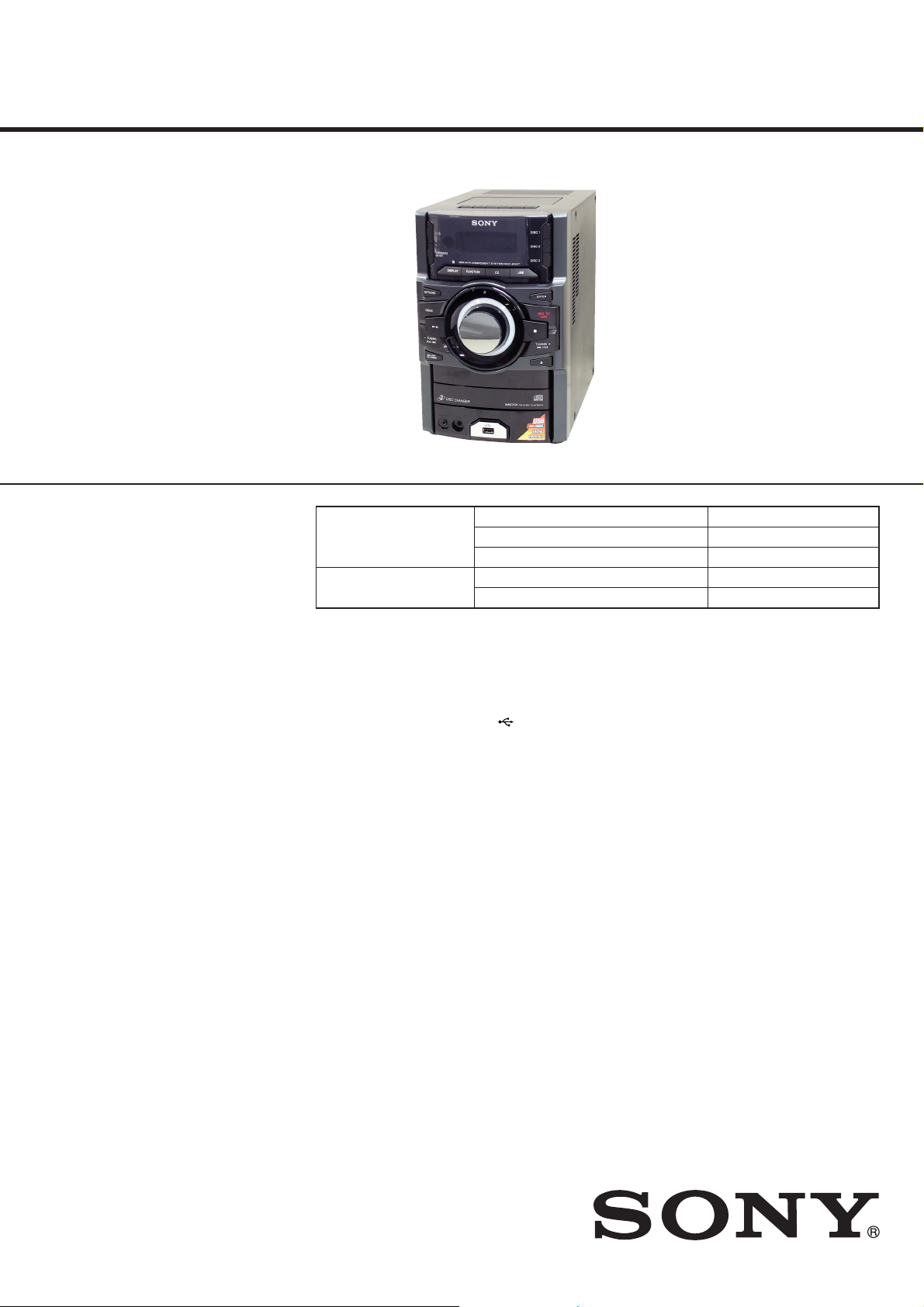
CD Section
Tape Deck Section
(HCD-EX6T/EX8T/EX9T)
Photo: HCD-EX9T
E Model
Model Name Using Similar Mechanism New
Mechanism Type CDM88CL-D1BD74UR
Optical Pick-up Block Name DA11MMVGP
Model Name Using Similar Mechanism HCD-EC69T/EC79T/EC99T
Tape Transport Mechanism Type TCM-J1 or CS-21SC-901TP
Amplifi er section
The following measured at AC 127 V,
60 Hz (Mexican model)
The following measured at AC 220 V,
50/60 Hz (Argentine model)
The following measured at AC 120 V,
220 V, 240 V, 50/60 Hz (Other models)
HCD-EX9/EX9T
Front Speaker:
Power output (rated):
Low channel
40 W + 40 W (at 8 Ω, 1 kHz, 1%
THD)
High channel
40 W + 40 W (at 8 Ω, 1 kHz, 1%
THD)
RMS output power (reference):
Low channel
85 W + 85 W (per channel at 8 Ω,
1 kHz)
High channel
85 W + 85 W (per channel at 8 Ω,
1 kHz)
Subwoofer:
RMS output power (reference):
125 W (at 4 Ω, 80 Hz)
HCD-EX8/EX8T
Power output (rated):
Low channel
50 W + 50 W (at 8 Ω, 1 kHz, 1%
THD)
High channel
50 W + 50 W (at 8 Ω, 1 kHz, 1%
THD)
SPECIFICATIONS
RMS output power (reference):
Low channel
100 W + 100 W (per channel at 8 Ω,
1 kHz)
High channel
100 W + 100 W (per channel at 8 Ω,
1 kHz)
HCD-EX6/EX6T
Power output (rated):
40 W + 40 W (at 6 Ω, 1 kHz, 1%
THD)
RMS output power (reference):
90 W + 90 W (per channel at 6 Ω,
1 kHz)
Inputs
PC IN (stereo mini jack):
Sensitivity 800 mV, impedance
22 kilohms
Outputs
PHONES (stereo mini jack):
accepts headphones with an
impedance of 8 Ω or more
SPEAKERS: impedance
HCD-EX9/EX9T/EX8/EX8T: 8 Ω
HCD-EX6/EX6T: 6 Ω
SUBWOOFER (HCD-EX9/EX9T only):
impedance 4 Ω
USB section
Supported bit rate:
MP3 (MPEG 1 Audio Layer-3):
32 kbps – 320 kbps, VBR
WMA: 48 kbps – 192 kbps
AAC: 48 kbps – 320 kbps
Sampling frequencies:
MP3 (MPEG 1 Audio Layer-3):
32/44.1/48 kHz
WMA: 44.1 kHz
AAC: 44.1 kHz
(USB) port:
Maximum current:
500 mA
CD player section
System:
Compact disc and digital audio
system
Laser Diode Properties
Emission Duration: Continuous
Laser Output*: Less than 44.6μW
* This output is the value
measurement at a distance of
200mm from the objective lens
surface on the Optical Pick-up
Block with 7mm aperture.
Frequency response: 20 Hz – 20 kHz
Signal-to-noise ratio: More than 90 dB
Dynamic range: More than 88 dB
Tape deck section (HCD-EX9T/
EX8T/EX6T only)
Recording system: 4-track 2-channel, stereo
Tuner section
FM stereo, FM/AM superheterodyne tuner
Antenna:
FM lead antenna
AM loop antenna
FM tuner section:
Tuning range:
87.5 MHz ‒ 108.0 MHz (50 kHz step)
Intermediate frequency: 225 kHz
AM tuner section:
Tuning range
Latin American models:
530 kHz ‒ 1,710 kHz (10 kHz step)
531 kHz ‒ 1,710 kHz (9 kHz step)
Other models:
531 kHz ‒ 1,602 kHz (9 kHz step)
530 kHz ‒ 1,610 kHz (10 kHz step)
Intermediate frequency: 53 kHz
– Continued on next page –
HCD-EX6/EX8/EX9
COMPACT DISC RECEIVER
HCD-EX6T/EX8T/EX9T
COMPACT DISC DECK RECEIVER
9-889-803-02
2010L04-1
2010.12
©
Sony Corporation
Published by Sony Techno Create Corporation
HCD-EX6/EX6T/EX8/EX8T/EX9/EX9T
General
Power requirements
Mexican model:
AC 127 V, 60 Hz
Argentine model:
AC 220 V, 50/60 Hz
Other models:
AC 120 V, 220 V or 230 V ‒ 240 V,
50/60 Hz, adjustable with voltage
selector
Power consumption
HCD-EX9/EX9T: 175 W
(0.5 W at the Power Saving Mode)
HCD-EX8/EX8T: 170 W
(0.5 W at the Power Saving Mode)
HCD-EX6/EX6T: 110 W
(0.5 W at the Power Saving Mode)
Dimensions (W/H/D) (excl. speakers)
Approx. 200 mm × 306 mm ×
350 mm
Mass (excl. speakers)
HCD-EX9: Approx. 6.7 kg
HCD-EX9T: Approx. 7.0 kg
HCD-EX8: Approx. 6.6 kg
HCD-EX8T: Approx. 6.9 kg
HCD-EX6: Approx. 5.6 kg
HCD-EX6T: Approx. 5.9 kg
Design and specifi cations are subject to
change without notice.
NOTES ON CHIP COMPONENT REPLACEMENT
• Never reuse a disconnected chip component.
• Notice that the minus side of a tantalum capacitor may be damaged by heat.
FLEXIBLE CIRCUIT BOARD REPAIRING
• Keep the temperature of soldering iron around 270 °C during
repairing.
• Do not touch the soldering iron on the same conductor of the
circuit board (within 3 times).
• Be careful not to apply force on the conductor when soldering
or unsoldering.
CAUTION
Use of controls or adjustments or performance of procedures
other than those specifi ed herein may result in hazardous radia-
tion exposure.
TABLE OF CONTENTS
1. SERVICING NOTES ............................................. 3
2. DISASSEMBLY
2-1. Side Panel (R)/(L) .......................................................... 7
2-2. Top Panel Section ........................................................... 7
2-3. Tape Mechanism Deck (HCD-EX6T/EX8T/EX9T) ....... 8
2-4. Front Panel Section ......................................................... 8
2-5. MAIN Board ................................................................... 9
2-6. Back Panel Section ......................................................... 10
2-7. CD Mechanism Section .................................................. 11
2-8. Belt (DLM3A) ................................................................ 11
2-9. Base Unit ......................................................................... 12
2-10. BD74 Board .................................................................... 12
3. TEST MODE ............................................................ 13
4. MECHANICAL ADJUSTMENTS ...................... 15
5. ELECTRICAL ADJUSTMENTS ........................ 15
6. DIAGRAMS
6-1. Block Diagram –CD/Tuner Section– .............................. 21
6-2. Block Diagram –Tape/Audio Section– ........................... 22
6-3. Block Diagram –Display/Power Supply Section– .......... 23
6-4. Printed Wiring Board –CD Section– .............................. 24
6-5. Schematic Diagram –CD Section– ................................. 25
6-6. Printed Wiring Board –USB Section– ............................ 26
6-7. Schematic Diagram –USB Section– ............................... 27
6-8. Printed Wiring Board –Panel Section– ........................... 28
6-9. Schematic Diagram –Panel Section– .............................. 29
6-10. Printed Wiring Board –USB-JACK Section– ................. 30
6-11. Schematic Diagram –USB-JACK Section– .................... 30
6-12. Printed Wiring Boards –MAIN-AMP Section– .............. 31
6-13. Schematic Diagram –MAIN-AMP Section (1/2)–.......... 32
6-14. Schematic Diagram –MAIN-AMP Section (2/2)–.......... 33
6-15. Printed Wiring Board –Power Supply Section– ............. 34
6-16. Schematic Diagram –Power Supply Section– ................ 35
6-17. Schematic Diagram –Tape Deck Section
(HCD-EX6T/EX8T/EX9T)– .......................................... 36
6-18. Printed Wiring Board –Tape Deck Section
(HCD-EX6T/EX8T/EX9T)– .......................................... 37
This appliance is classifi ed as
a CLASS 1 LASER product.
This marking is located on the
rear exterior.
SAFETY-RELATED COMPONENT WARNING!
COMPONENTS IDENTIFIED BY MARK 0 OR DOTTED LINE
WITH MARK 0 ON THE SCHEMATIC DIAGRAMS AND IN
THE PARTS LIST ARE CRITICAL TO SAFE OPERATION.
REPLACE THESE COMPONENTS WITH SONY PARTS
WHOSE PART NUMBERS APPEAR AS SHOWN IN THIS
MANUAL OR IN SUPPLEMENTS PUBLISHED BY SONY.
2
7. EXPLODED VIEWS
7-1. Overall Section ............................................................... 46
7-2. Front Panel Section ......................................................... 47
7-3. Top Panel Section (HCD-EX6T/EX8T/EX9T) .............. 48
7-4. Chassis Section ............................................................... 49
7-5. MAIN Board Section ...................................................... 50
7-6. CD Mechanism Section (CDM88CL-D1BD74UR) ....... 51
8. ELECTRICAL PARTS LIST .............................. 52
Accessories are given in the last of the electrical parts list.
HCD-EX6/EX6T/EX8/EX8T/EX9/EX9T
SECTION 1
SERVICING NOTES
NOTES ON HANDLING THE OPTICAL PICK-UP
BLOCK OR BASE UNIT
The laser diode in the optical pick-up block may suffer electrostatic break-down because of the potential difference generated by
the charged electrostatic load, etc. on clothing and the human body.
During repair, pay attention to electrostatic break-down and also
use the procedure in the printed matter which is included in the
repair parts.
The fl exible board is easily damaged and should be handled with
care.
NOTES ON LASER DIODE EMISSION CHECK
The laser beam on this model is concentrated so as to be focused
on the disc refl ective surface by the objective lens in the optical
pickup block. Therefore, when checking the laser diode emission,
observe from more than 30 cm away from the objective lens.
UNLEADED SOLDER
Boards requiring use of unleaded solder are printed with the leadfree mark (LF) indicating the solder contains no lead.
(Caution: Some printed circuit boards may not come printed with
the lead free mark due to their particular size)
: LEAD FREE MARK
Unleaded solder has the following characteristics.
• Unleaded solder melts at a temperature about 40 °C higher
than ordinary solder.
Ordinary soldering irons can be used but the iron tip has to be
applied to the solder joint for a slightly longer time.
Soldering irons using a temperature regulator should be set to
about 350 °C.
Caution: The printed pattern (copper foil) may peel away if
the heated tip is applied for too long, so be careful!
• Strong viscosity
Unleaded solder is more viscous (sticky, less prone to fl ow)
than ordinary solder so use caution not to let solder bridges
occur such as on IC pins, etc.
• Usable with ordinary solder
It is best to use only unleaded solder but unleaded solder may
also be added to ordinary solder.
RELEASING THE DISC TRAY LOCK
The disc tray lock function for the antitheft of an demonstration
disc in the store is equipped.
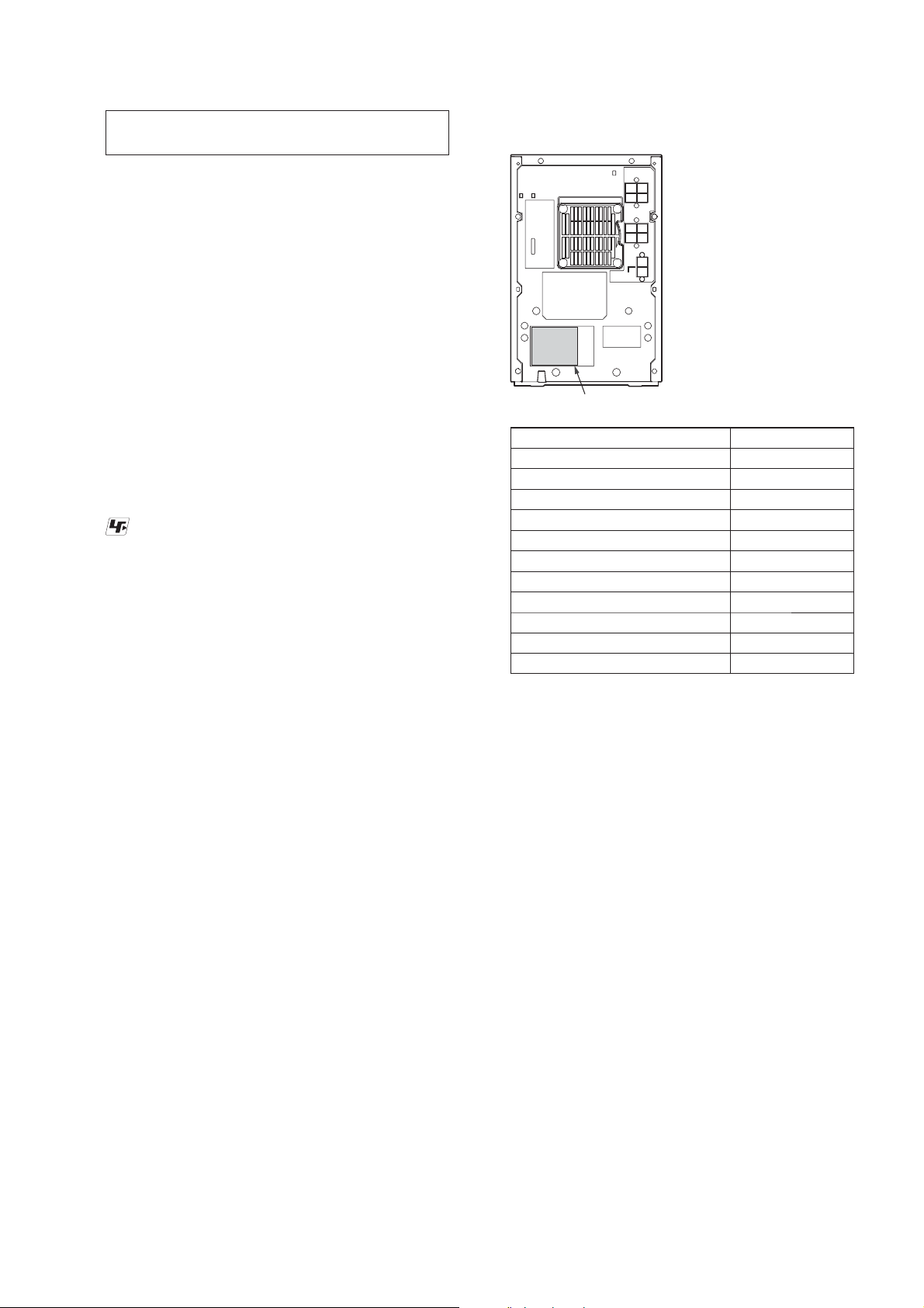
MODEL IDENTIFICATION
– Back Panel –
Model Number Label
Model Part No.
EX6T: E4 model
EX6: AR model
EX8T: E4 model
EX8: AR model
EX8: MX model
EX9T: E4 model
EX9: AR model
EX9: MX model
EX6: E2, E51 models
EX8: E2, E51 models
EX9: E2, E51 models
• Abbreviation
E4 : 220 – 240V AC area in E model
AR : Argentina model
MX : Mexican model
E2 : 120V AC area in E model
E51 : Chilean and Peruvian models
: Since the HCD-EX6/EX8/EX9: E2 and E51 models have their
*
4-178-730-0[]
4-178-731-0[]
4-178-733-0[]
4-178-734-0[]
4-178-735-0[]
4-178-736-0[]
4-178-737-0[]
4-178-738-0[]
*
*
*
model number labels marked directly on the back panel, the
model number labels have no relative part numbers.
Because of this, determine the model through the marked model
number when comparing the difference between these models.
Releasing Procedure:
1. Press [
] button to turn the power on.
?/1
2. Press the [FUNCTION] button to select CD function.
3. While pressing the [x] button, press the [Z] button for more 5
seconds).
4. The message “UNLOCKED” is displayed and the disc tray is
unlocked.
Note: When “LOCKED” is displayed, the slot lock is not released by turn-
ing power on/off with the [
?/1
] button.
3

HCD-EX6/EX6T/EX8/EX8T/EX9/EX9T
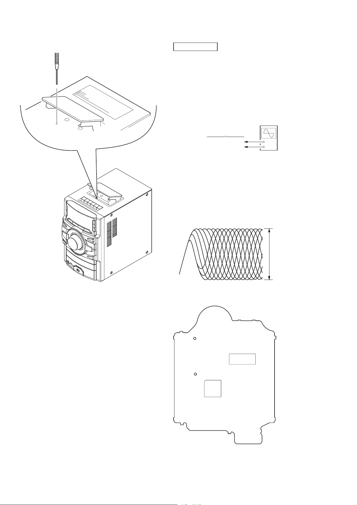
HOW TO OPEN THE TRAY WHEN POWER SWITCH TURN OFF
Note: Please take out the side panel (R) from a set refer to DISASSEMBLY (page 7).
Pull the tray by the hand.
2
HOW TO REMOVE THE KNOB (VOL)
VOL knob
2
state of opening the CD tray
lever
gear
front panel block
(back view)
Turn a gear by a driver
1
till a lever rises up
to the position of the figure.
Push the VOL knob by the flat head driver.
hole
1
4

HCD-EX6/EX6T/EX8/EX8T/EX9/EX9T
CAPACITOR DISCHARGE FOR ELECTRIC SHOCK PREVENTION
Note: Please take out the side panel (R) from a set refer to DISASSEMBLY (page 7).
PT-POWER board
(Right side view)
In checking the PT-POWER board, make a capacitor discharge
of C013 and C014 for electric shock prevention.
PRECAUTION WHEN INSTALLING A NEW OP UNIT/
PRECAUTION BEFORE UNSOLDERING THE STATIC
ELECTRICITY PREVENTION SOLDER BRIDGE
PT-POWER board
C013 C014
00 ȍW 00 ȍW
HOW TO DISTINGUISH TAPE MECHANISM DECK
(HCD-EX6T/EX8T/EX9T only)
Two kinds of tape mechanism decks installed by this set exist.
Please do the repair exchange after confi rming which tape mecha-
nism deck set of the repair according to how to distinguish the
fi gure below.
When installing a new OP unit, be sure to connect the fl exible
printed circuit board fi rst of all before removing the static electric-
ity prevention solder bridge by unsoldering.
Remove the static electricity prevention solder bridge by unsoldering after the fl exible printed circuit board has already been con-
nected.
(Do not remove nor unsolder the solder bridge as long as the OP
unit is kept standalone.)
motor
Metal part: TCM-J1
Mold part: CS-21SC-901TP
Tape Deck Name
TCM-J1 A-1527-851-A
CS-21SC-901TP 1-797-575-11
Tape Deck
Part No.
tape deck
Belt Part No.
2-670-389-01 BELT (1)
3-214-817-01 BELT (FR)
2-688-621-01 BELT (R/F)
2-688-622-01 BELT (MAIN)
5
HCD-EX6/EX6T/EX8/EX8T/EX9/EX9T
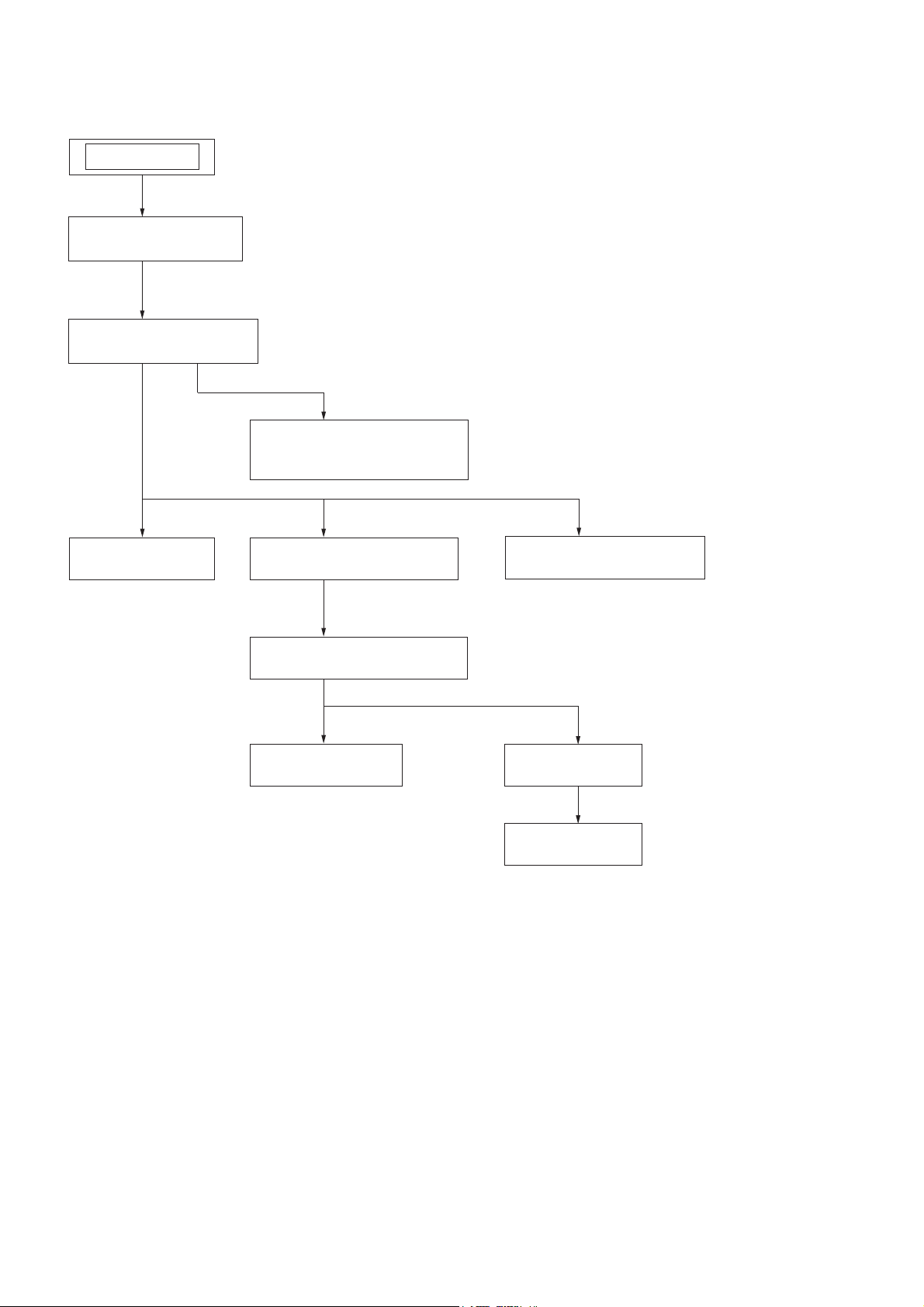
SECTION 2
DISASSEMBLY
• This set can be disassembled in the order shown below.
SET
2-1. SIDE PANEL (R)/(L)
(Page 7)
2-2. TOP PANEL SECTION
(Page 7)
2-3. TAPE MECHANISM DECK
(HCD-EX6T/EX8T/EX9T)
(Page 8)
2-5. MAIN BOARD
(Page 9)
2-4. FRONT PANEL SECTION
(Page 8)
2-7. CD MECHANISM SECTION
(Page 11)
2-8. BELT (DLM3A)
(Page 11)
2-6. BACK PANEL SECTION
(Page 10)
2-9. BASE UNIT
(Page 12)
2-10. BD74 BOARD
(Page 12)
6
Note: Follow the disassembly procedure in the numerical order given.
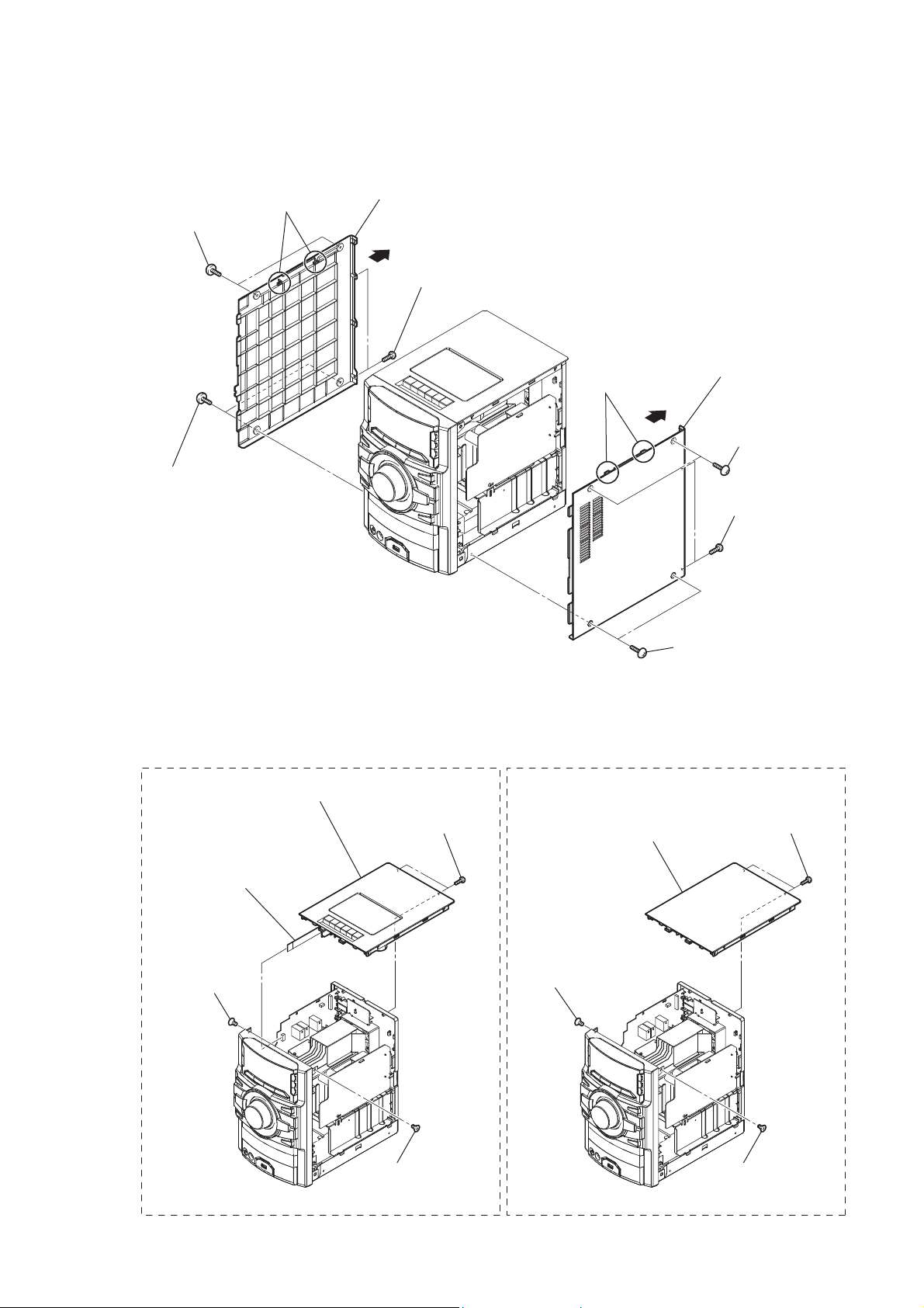
2-1. SIDE PANEL (R)/(L)
HCD-EX6/EX6T/EX8/EX8T/EX9/EX9T
8 two screws
(case 3 TP2)
7 two screws
(case 3 TP2)
0 two claws
qs side panel (L)
qa
9 two screws
(+BVTP 3 u10)
6 side panel (R)
4 two claws
5
2 two screws
(case 3 TP2)
3 two screws
(+BVTP 3 u10)
2-2. TOP PANEL SECTION
EX6T/EX8T/EX9T EX6/EX8/EX9
5 top panel section
3 two screws
(+BVTP 3 u10)
4 wire (flat type) (9 core)
(CN605)
2 screw
(+KTP 3 u10)
2 screw
(+KTP 3 u10)
1 two screws
(case 3 TP2)
4 top panel section
3 two screws
(+BVTP 3 u10)
1 screw
(+KTP 3 u10)
1 screw
(+KTP 3 u10)
7
HCD-EX6/EX6T/EX8/EX8T/EX9/EX9T
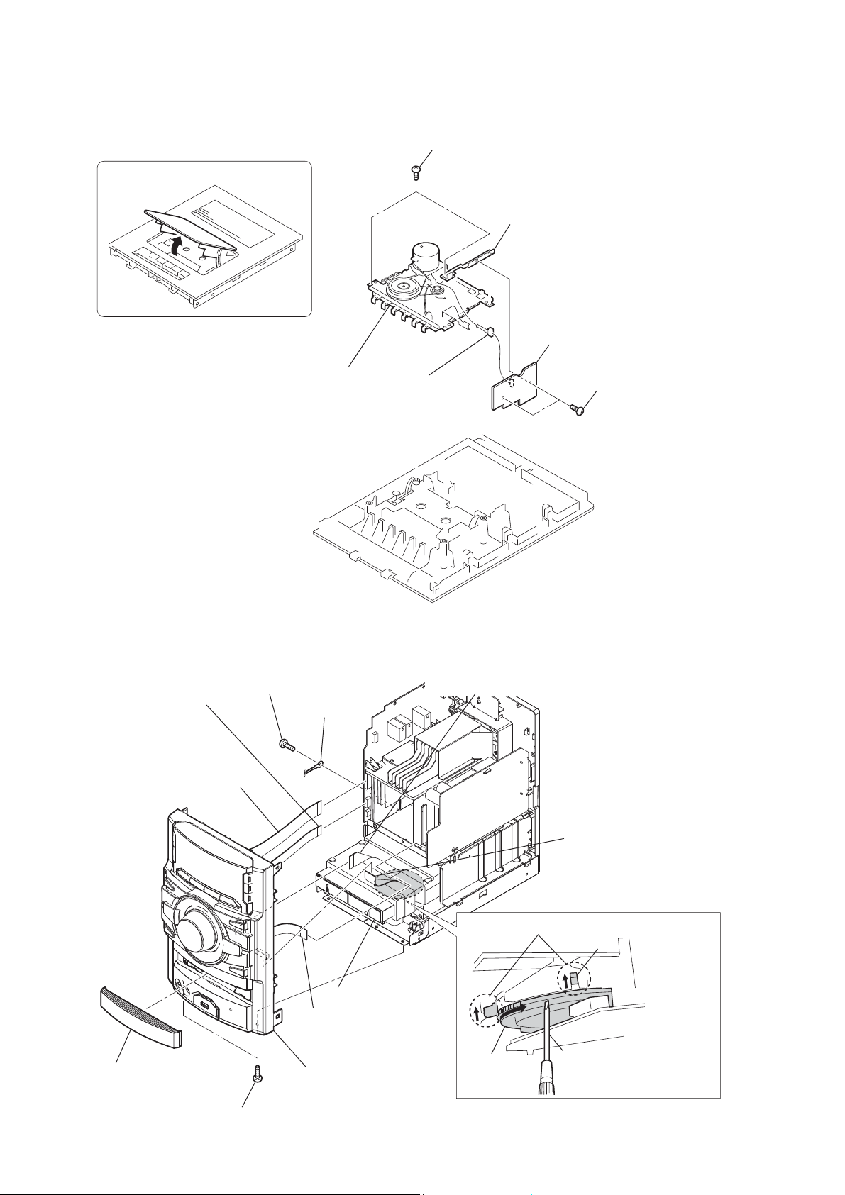
2-3. TAPE MECHANISM DECK (HCD-EX6T/EX8T/EX9T)
1 Open the cassette box.
2 four screws
(
+BVTP 2.6 u8
)
4 bracket (deck)
6 DECK board
2-4. FRONT PANEL SECTION
9 screw
5 wire (flat type) (9 core)
(CN604)
4 wire (flat type) (19 core)
(CN603) (EX6/EX8/EX9)
wire (flat type) (21 core)
(CN602) (EX6T/EX8T/EX9T)
(+BVTP 3 u10)
7 tape mechanism deck
0 lug
5 CN501 (8P)
8 wire (flat type) (25 core)
(CN902)
3 two screws
(
+BVTP 3 u6
)
7 wire (flat type) (13 core)
(CN302)
state of opening the CD tray
lever
2 Pull the tray by hand.
6 wire (flat type) (11 core)
(CN011)
Turn a gear by a driver
3 loading panel
qs front panel section
gear
qa three screws
(+BVTT 3 u8)
1
till a lever rises up to the
position of the figure.
8
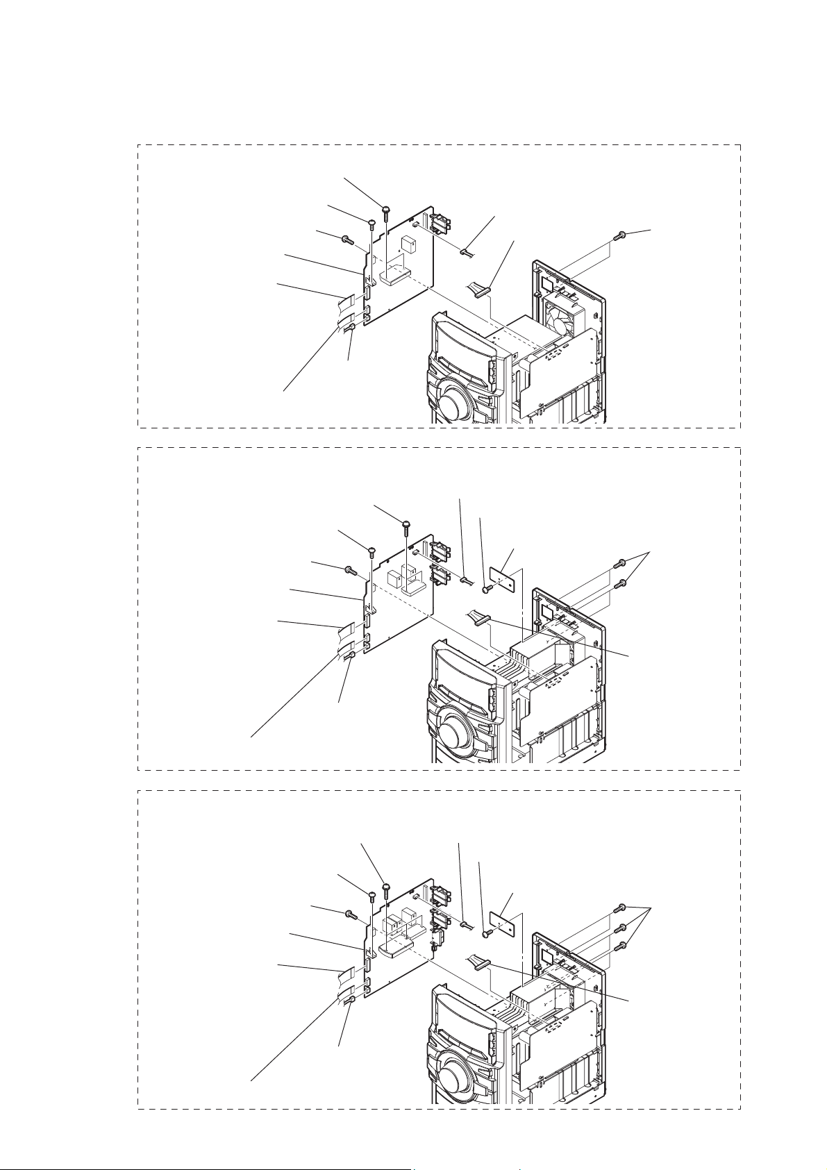
2-5. MAIN BOARD
EX6/EX6T
q; MAIN board
3 wire (flat type) (19 core)
(CN603) (EX6)
wire (flat type) (21 core)
(CN602) (EX6T)
8 two screws
(transistor)
9 screw
(+BVTP 3 u10)
7 screw
(+BVTP 3 u10)
4 wire (flat type) (9 core)
(CN604)
5 CN609 (3P)
HCD-EX6/EX6T/EX8/EX8T/EX9/EX9T
2 CN701 (3P)
1 CN012 (10P)
6 two screws
(+BVTP 3 u10)
EX8/EX8T
qa screw
(+BVTP 3 u10)
9 screw
(+BVTP 3 u10)
qs MAIN board
5 wire (flat type) (19 core)
(CN603) (EX8)
wire (flat type) (21 core)
(CN602) (EX8T)
6 wire (flat type) (9 core)
(CN604)
EX9/EX9T
qa screw
(+BVTP 3 u10)
9 screw
(+BVTP 3 u10)
qs MAIN board
0 two screws
(transistor)
7 CN609 (3P)
0 four screws
(transistor)
4 CN701 (3P)
1 screw
(+BVTP 3 u10)
2 HOLD board
4 CN701 (3P)
1 screw
(+BVTP 3 u10)
2 HOLD board
8 four screws
(+BVTP 3 u10)
3 CN012 (10P)
8 six screws
(+BVTP 3 u10)
5 wire (flat type) (19 core)
(CN603) (EX9)
wire (flat type) (21 core)
(CN602) (EX9T)
6 wire (flat type) (9 core)
(CN604)
3 CN010 (13P)
7 CN609 (3P)
9

HCD-EX6/EX6T/EX8/EX8T/EX9/EX9T
2-6. BACK PANEL SECTION
EX6/EX6T
1 CN701 (3P)
3 two screws
(+BVTP 3 u10)
2 Cut the clamp.
4 six screws
(+BVTP 3 u10)
5 back panel section
Installation of the power cord
when assembling the set.
EX8/EX8T
1 screw
(+BVTP 3 u10)
EX9/EX9T
1 screw
(+BVTP 3 u10)
3 CN701 (3P)
3 CN701 (3P)
2 HOLD board
2 HOLD board
5 four screws
(+BVTP 3 u10)
4 Cut the clamp.
6 six screws
(+BVTP 3 u10)
7 back panel section
5 six screws
(+BVTP 3 u10)
4 Cut the clamp.
Installation of the power cord
when assembling the set.
Installation of the power cord
when assembling the set.
10
6 six screws
(+BVTP 3 u10)
7 back panel section
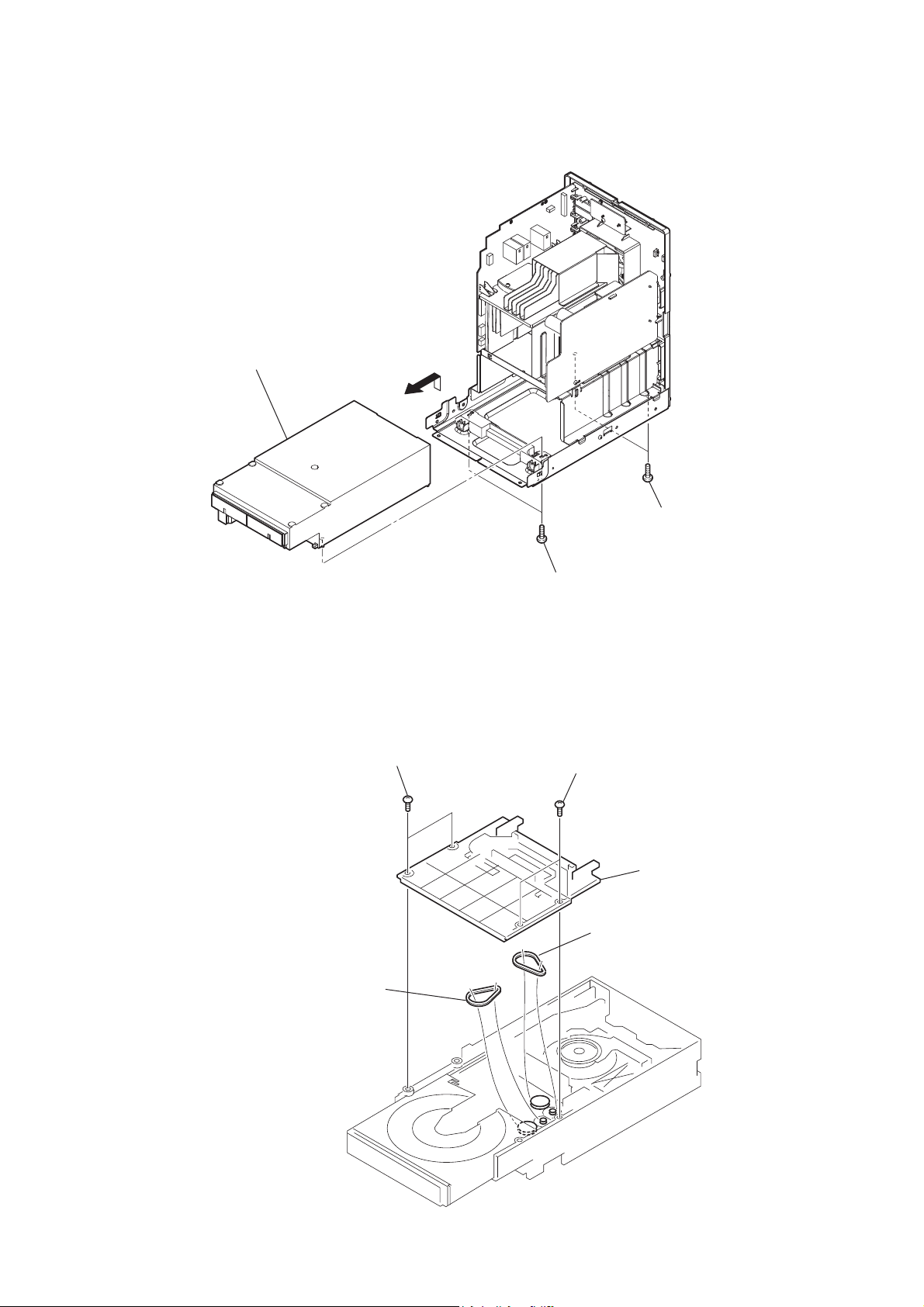
2-7. CD MECHANISM SECTION
4 CD mechanism section
HCD-EX6/EX6T/EX8/EX8T/EX9/EX9T
3
2-8. BELT (DLM3A)
1 two screws
1 two screws
(+BVTP 3 u10)
2 two screws
(+BVTP 3 u10)
2 two screws
3 cover
4 belt (DLM3A)
5 belt (DLM3A)
11
HCD-EX6/EX6T/EX8/EX8T/EX9/EX9T
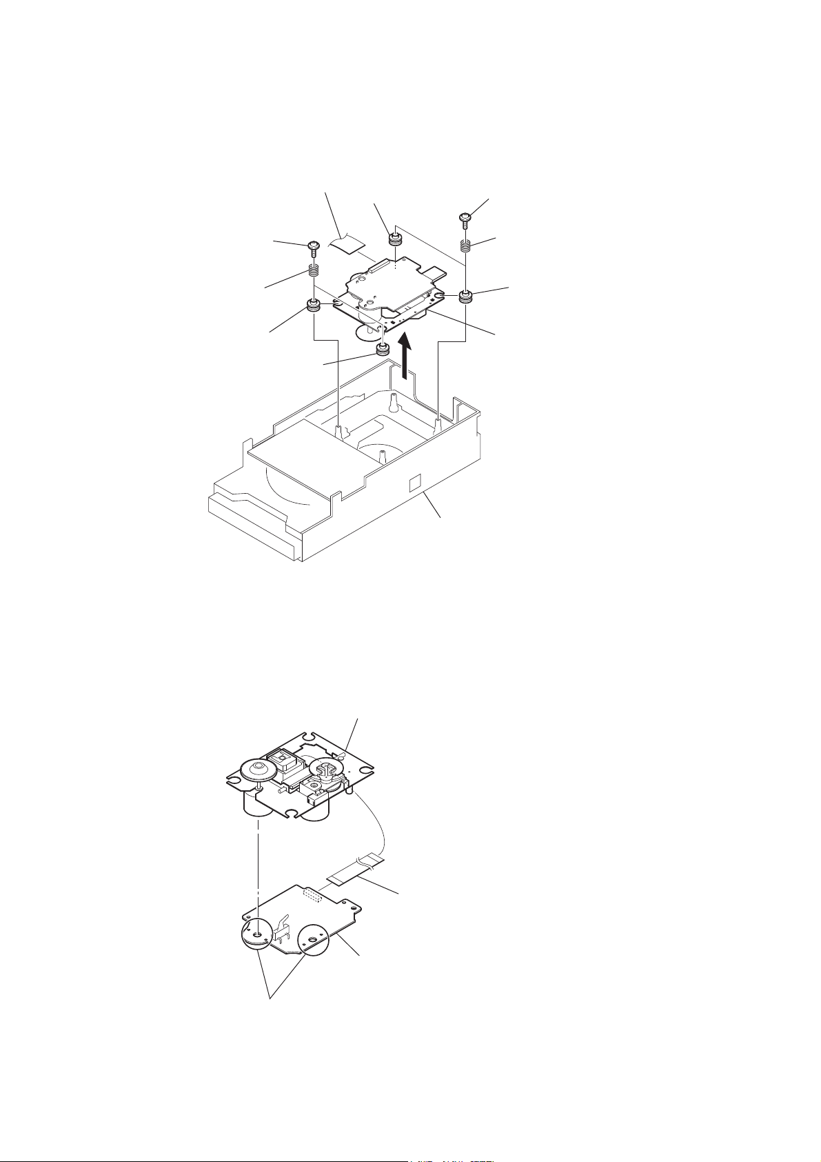
2-9. BASE UNIT
1 wire (flat type) (25 core)
(CN403)
8 insulator
2 two floating
(+PTPWH M2.6)
screw
4 two floating
(+PTPWH M2.6)
5 two coil springs
(insulator)
screw
9 insulator
0 insulator
6
CD mechanism block
(bottom view)
3 two coil springs
(insulator)
7 insulator
qa base unit
2-10. BD74 BOARD
OP base assy
1 wire (flat type) (16 core)
(CN201)
3 BD74 board
2 Remove the four solders.
12

HCD-EX6/EX6T/EX8/EX8T/EX9/EX9T
SECTION 3
TEST MODE
COLD RESET
The cold reset clears all data including preset data stored in the
memory to initial conditions. Execute this mode when returning
the set to the customer.
Procedure:
1. In the standby status, press the [
] button to turn the power
?/1
on.
2. Press three buttons of [x], [FUNCTION] and [
] simultane-
?/1
ously.
3. When “RESET” appears, the set enters standby status.
PANEL TEST MODE
Enter The Panel Test Mode
Procedure:
1. In the standby status, press the [
] button to turn the power
?/1
on.
2. Press three buttons of [DISPLAY], [x] and [OPTIONS] simultaneously.
3. When the panel test mode is activated, all LEDs and segments
of the liquid crystal display panel are all turned on.
Version Check
Procedure:
1. In the panel test mode (all LEDs and segments of the liquid
crystal display panel are turned on), press the [FUNCTION]
button.
2. On the liquid crystal display panel, date and version are displayed “xxxxVxxx”.
3. From this status, press the [u] button, and the destination and
model name are displayed.
4. To release from this mode, press three buttons of [DISPLAY],
[x] and [OPTIONS] simultaneously.
Key Test Mode
Procedure:
1. In the panel test mode (all LEDs and segments of the liquid
crystal display panel are turned on), press the [x] button.
2. The message “KEY0 0 0” displayed. Whenever any buttons
are pressed and the [VOLUME] control is turned, the value is
changed.
3. To release from this mode, press three buttons of [DISPLAY],
[x] and [OPTIONS] simultaneously.
CD REPEAT 5 LIMIT CANCEL MODE
Number of repeats for CD playback is 5 times when the repeat
mode is “REPEAT”. This mode enables CD to repeat playback for
limitless times.
Procedure:
1. Press the [
] button to turn the power on.
?/1
2. Press the [FUNCTION] button to select CD function.
3. Press three buttons of [DISPLAY], [x] and [TUNING + M
] simultaneously.
L
4. It enters the CD repeat 5 limit cancel mode and displays “NO
LIMIT”.
5. To release this mode, press the [
] button to turn the power
?/1
off.
CD TRAY LOCK
This mode is for the antitheft of CD disc in shop. (not for transport)
Procedure:
1. Press the [
] button to turn the power on.
?/1
2. Press the [FUNCTION] button to select CD function.
3. Insert a disc.
4. While pressing the [x] button, press the [Z] button for more 5
seconds.
5. The message “LOCKED” is displayed and the disc tray is
locked. (Even if releasing from this mode, the disc tray is still
locked)
6. If press the [Z] button to eject the disc, the message “LOCKED”
is displayed and can not eject the disc.
7. To release this lock, while pressing the [
] button for 5 seconds again.
[
Z
] button, press the
x
8. The message “UNLOCKED” is displayed and the disc tray is
unlocked.
CD POWER MANAGE
This mode is for switch the CD power supply on/off. Even if this
state pulls out AC plug, it is held.
Procedure:
1. Press the [
] button to turn the power on.
?/1
2. Press the [FUNCTION] button to select CD function.
3. Press the [
] button again to turn the power off (standby).
?/1
4. After pressing the [DISPLAY] button, while pressing the [x]
button, press the [
?/1
] button.
5. It turns power on and display “CD/USB”, then display “PWR
ON” or “PWR OFF”.
CHANGE-OVER THE AM TUNING INTERVAL
The AM tuning interval can be changed over 9 kHz or 10 kHz.
Procedure:
1. Press the [
] button to turn the power on.
?/1
2. Press the [FUNCTION] button to select TUNER AM function.
3. Press the [
] button again to turn the power off (standby).
?/1
4. After pressing the [DISPLAY] button, while pressing the
[TUNING + M L] button, press the [
?/1
] button.
5. It turns power on and display “9k STEP” or “10k STEP”, and
thus the tuning interval is changed over.
CD SHIP MODE
This mode can run the CD sled motor optionally. Use this mode,
for instance, when cleaning the optical pick-up.
Procedure:
1. Press the [
] button to turn the power on.
?/1
2. Confi rm there is no disc in all trays.
3. Press the [FUNCTION] button to select CD function.
4. Press two buttons of [u] and [
] simultaneously.
?/1
5. Set to the CD ship mode (chucking on).
6. After blink “STANDBY”, “LOCK” is displayed, disconnect
the AC plug.
CD SHIP AND COLD RESET
Procedure:
1. Press the [
] button to turn the power on.
?/1
2. Confi rm there is no disc in all trays.
3. Press the [FUNCTION] button to select CD function.
4. Press three buttons of [CD], [– TUNING l m] and [
?/1
simultaneously.
5. After blink “STANDBY”, “RESET” is displayed, disconnect
the AC plug.
]
13

HCD-EX6/EX6T/EX8/EX8T/EX9/EX9T
CD SERVO TEST MODE
This mode can check the servo system operations of the optical
pick-up system (= optical unit + BD74 board).
Note 1: Do not enter the this mode while any other test mode is in prog-
ress.
Note 2: Do not enter any other test mode while the this mode is in prog-
ress.
How to Enter the CD Servo Test Mode
Procedure:
1. Press the [
] button to turn the power on.
?/1
2. Press the [FUNCTION] button to select CD function.
3. Press three buttons of [u], [TUNING + M L] and [
?/1
simultaneously.
4. It enters the CD servo test mode and displays “xx xxxx”.
How to Exit from the CD Servo Test Mode
Procedure:
1. Press three buttons of [u], [TUNING + M L] and [
?/1
simultaneously.
2. It releases from the CD Servo Test Mode and returns to the
ordinary CD function.
Key Operation:
[TUNING + M L], [– TUNING l m]:
Use these keys to move the cursor to the right digit
or to the left digit in the six-digit number, when
changing the numeric value.
Press [TUNING + M L] to move the cursor to
the right, and press [– TUNING l m] to return
the cursor to the left.
CD SERVICE MODE
This mode can move the SLED of the optical pick-up, and also can
turn the optical pick-up laser power on and off.
Procedure:
1. Press the [
2. Press three buttons of [u], [ENTER] and [
] button to turn the power on.
?/1
] simultane-
?/1
ously.
3. Press the [FUNCTION] button to select CD function.
4. It enters the CD service mode and displays “SERVICE”.
5. To release from this mode, press three buttons of [u], [ENTER] and [
] simultaneously.
?/1
Key Operation:
[TUNING + M L], [– TUNING l m]:
Use these keys to move the SLED. When [TUN-
ING + M L] is pressed in this mode, the SLED
moves to outer circumference and the message
“SLED OUT” is displayed.
When [– TUNING
l m
] is pressed in this
mode, the SLED moves to inner circumference and
the message “SLED IN” is displayed.
[CD]:
Use this key to turn the optical pick-up laser power
on and off. When the laser power is turned on, the
message “LD ON” is displayed. When the laser
power is turned off, the message “LD OFF” is displayed.
CD FACTORY MODE
Note 1: Do not enter the this mode while any other testmode is in prog-
ress.
Note 2: Do not enter any other test mode while the this mode is in prog-
ress.
Procedure:
1. Press the [
] button to turn the power on.
?/1
2. Press the [FUNCTION] button to select CD function
3. Press three buttons of [u], [USB] and [
] simultaneously.
?/1
4. It enters the CD factory mode and the message “FACTORY”
is displayed. When the [CD] button is pressed four times, the
]
following message (initial display) is displayed.
– – ON S
S character mode setting
]
Key Operation:
[CD]:
The display changes in the following order when-
[DSGX]:
RF gain setting changes whenever the button is
“-- --”: No gain fi xation.
“AL”: Fix to the gain for AL disc.
“RW”: Fix to the gain for RW disc.
[USB]:
Tracking servo setting changes whenever the but-
“ON”: Tracking servo ON.
“OFF”: Tracking servo OFF.
[FUNCTION]:
S character mode setting changes whenever the but-
“ ”: S character mode OFF.
“S”: S character mode ON.
5. To release from this mode, press three buttons of [u], [USB]
and [
?/1
Tracking servo setting
RF gain setting
ever the button is pressed.
(Initial display)
FSCAG ** (**: Focus AGC value)
TRKAG ** (**: Track AGC value)
RF_AG ** (**: RF AGC value)
pressed.
ton is pressed.
ton is pressed.
] simultaneously.
14
SECTION 4
MECHANICAL ADJUSTMENTS
HCD-EX6/EX6T/EX8/EX8T/EX9/EX9T
SECTION 5
ELECTRICAL ADJUSTMENTS
HCD-EX6T/EX8T/EX9T only:
Precaution
1. Clean the following parts with a denatured-alcohol-moistened
swab:
record/playback head pinch roller
erase head rubber belts
capstan idlers
2. Demagnetize the record/playback head with a head demagnetizer. (Do not bring the head magnetizer close to the erase
head.)
3. Do not use a magnetized screwdriver for the adjustments.
4. After the adjustments, apply suitable locking compound to the
parts adjusted.
5. The adjustments should be performed with the rated power
supply voltage unless otherwise noted.
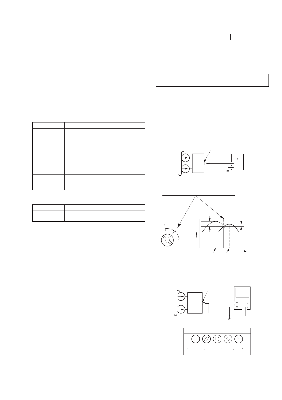
Torque Measurement
Mode Torque meter Meter reading
FWD CQ-102AS
FWD
Back tension
FF CQ-201AS
REV CQ-201B
CQ-102C
2.0 – 8.0 mN • m
(20 to 80 g • cm)
(0.28 – 1.12 oz • inch)
0.15 – 0.6 mN • m
(1.5 to 6 g • cm)
(0.021 – 0.083 oz • inch)
5 – 17.7 mN • m
(50 to 177 g • cm)
(0.7 – 2.48 oz • inch)
5 – 17.7 mN • m
(50 to 177 g • cm)
(0.7 – 2.48 oz • inch)
Tape Tension Measurement
Mode Tension meter Meter reading
FWD CQ-403A
more than 80 g
(more than 2.82 oz)
DECK SECTION
0 dB = 0.775V
HCD-EX6T/EX8T/EX9T only:
1. Demagnetize the record/playback head with a head demagnetizer.
2. Do not use a magnetized screwdriver for the adjustments.
TEST TAPE
Tape Signal Used for
P-4-A063 6.3 kHz, –10 dB Azimuth Adjustment
RECORD/PLAYBACK HEAD AZIMUTH ADJUSTMENT
Adjustment Location: Record/Playback Head (See page 16)
Note: Perform this adjustments for both decks.
Procedure:
1. Mode: Playback
test tape
P-4-A063
(6.3 kHz, –10 dB)
USB-JACK board
PHONES jack
(J551)
set
level meter
+
–
2. Turn the adjustment screw and check output peaks. If the peaks
do not match for L-CH and R-CH, turn the adjustment screw
so that outputs match within 1 dB of peak.
Output
level
within
1 dB
within
1 dB
L-CH
peak
R-CH
Screw
position
peak
L-CH
peak
R-CH
peak
Screw
position
3. Mode: Playback
test tape
P-4-A063
(6.3 kHz, –10 dB)
in phase 45º 90º 135º 180º
USB-JACK board
PHONES jack
(J551)
set
waveform of oscilloscope
good wrong
oscilloscope
H
V
4. After the adjustments, apply suitable locking compound to the
pats adjusted.
15
HCD-EX6/EX6T/EX8/EX8T/EX9/EX9T
Adjustment Location: Record/Playback Head
CD SECTION
Note:
1. CD Block is basically constructed to operate without adjustment.
2. Use YEDS-18 disc (Part No. 3-702-101-01) unless otherwise indicated.
3. Use an oscilloscope with more than 10 MΩ impedance.
4. Clean the object lens by an applicator with neutral detergent when the
signal level is low than specifi ed value with the following checks.
5. Check the focus bias check when optical pick-up block is replaced.
FOCUS BIAS CHECK
oscilloscope
(DC range)
BD74 board
CL102 (RFOUT)
CL117 (VREF)
Procedure:
1. Connect the oscilloscope to CL102 (RFOUT) and CL117
(VREF) on the BD74 board.
2. Press the [
] button to turn the power on, and press the
?/1
[FUNCTION] button to select CD function.
3. Set disc (YEDS-18) and press the [u] button to playback.
4. Confi rm that oscilloscope waveform is as shown in the fi gure
below (eye pattern).
A good eye pattern means that the diamond shape (◊) in the
center of the waveform can be clearly distinguished.
+
–
VOLT/DIV: 200 mV
TIME/DIV: 500 ns
Checking Location:
– BD74 Board (Side B) –
CL117
(VREF)
CL102
(RFOUT)
IC101
level:
1.1 ± 0.4 Vp-p
IC301
16
HCD-EX6/EX6T/EX8/EX8T/EX9/EX9T
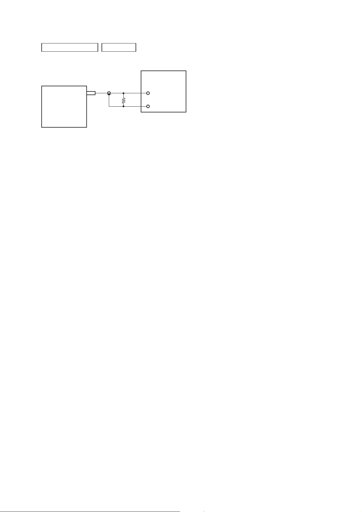
TUNER SECTION
FM AUTO STOP CHECK
set
0 dB = 1 μV
signal
generator
+
75 :
–
Procedure:
1. Turn the power on.
2. Input the following signal from Signal Generator to FM antenna input directly.
Carrier frequency : A = 87.5 MHz, B = 98 MHz, C = 108 MHz
Deviation : 75 kHz
Modulation : 1 kHz
ANT input : 35 dBu (EMF)
Note: Please use 75 ohm “coaxial cable” to connect SG and the set. You
cannot use video cable for checking.
Please use SG whose output impedance is 75 ohm.
3. Set to FM tuner function and scan the input FM signal with
automatic scanning.
4. Confi rm that input Frequency of A, B and C detected and auto-
matic scanning stops.
The stop of automatic scanning means “The station signal is received in good condition”.
17

HCD-EX6/EX6T/EX8/EX8T/EX9/EX9T
SECTION 6
• Circuit Boards Location
DIAGRAMS
REG board
PANEL board
USB board
DECK board
(HCD-EX6T/EX8T/EX9T)
USB-JACK board
MAIN board
PT-POWER board
BD74 board
18

HCD-EX6/EX6T/EX8/EX8T/EX9/EX9T
THIS NOTE IS COMMON FOR PRINTED WIRING BOARDS AND SCHEMATIC DIAGRAMS.
(In addition to this, the necessary note is printed in each block.)
For Printed Wiring Boards.
Note:
• X : Parts extracted from the component side.
• Y : Parts extracted from the conductor side.
• W : Indicates side identifi ed with part number.
• : Pattern from the side which enables seeing.
(The other layers’ patterns are not indicated.)
Caution:
Pattern face side:
(SIDE B)
Parts face side:
(SIDE A)
• Abbreviation
AR : Argentina model
E2 : 120V AC area in E model
E4 : 220 – 240V AC area in E model
E51 : Chilean and Peruvian models
MX : Mexican model
Parts on the pattern face side seen
from the pattern face are indicated.
Parts on the parts face side seen from
the parts face are indicated.
For Schematic Diagrams.
Note:
• All capacitors are in μF unless otherwise noted. (p: pF) 50
WV or less are not indicated except for electrolytics and
tantalums.
• All resistors are in Ω and 1/4 W or less unless otherwise
specifi ed.
• f : Internal component.
• 2 : Nonfl ammable resistor.
• C : Panel designation.
Note: The components identifi ed by mark 0 or dotted
line with mark 0 are critical for safety.
Replace only with part number specifi ed.
• A : B+ Line.
• B : B– Line.
• H : Adjustment for repair.
• Voltages and waveforms are dc with respect to ground
under no-signal (detuned) conditions.
– BD74 Board –
no mark : CD PLAY
– Other Boards –
no mark : TUNER (FM/AM)
( ) : CD PLAY
< > : TAPE PLAY
[ ] : TAPE REC
* : Impossible to measure
• Voltages are taken with VOM (Input impedance 10 MΩ).
Voltage variations may be noted due to normal production
tolerances.
• Waveforms are taken with a oscilloscope.
Voltage variations may be noted due to normal production
tolerances.
• Circled numbers refer to waveforms.
• Signal path.
F : TUNER (FM)
f : TUNER (AM)
J : CD
E : USB
q : PC IN
d : TAPE PLAY
: TAPE REC
• Abbreviation
AR : Argentina model
E2 : 120V AC area in E model
E4 : 220 – 240V AC area in E model
E51 : Chilean and Peruvian models
MX : Mexican model
19
HCD-EX6/EX6T/EX8/EX8T/EX9/EX9T
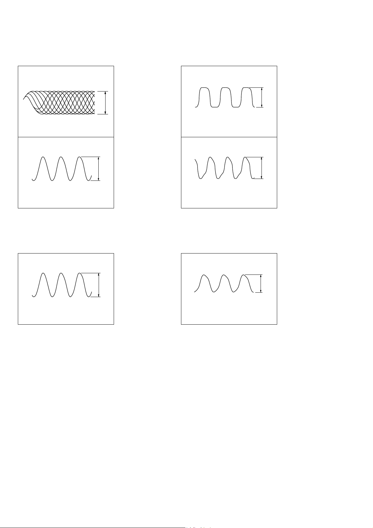
• Waveforms
– BD74 Board –
1 IC101 2 (RFOUT)
(CD play mode)
200 mV/DIV, 500 nsec/DIV
2 IC101 us (XOUT)
16.934 MHz
1 V/DIV, 20 nsec/DIV
0.7 to 1.5 Vp-p
2.8 Vp-p
– PANEL Board –
1 IC301 qf (X1A)
32.768 kHz
1 V/DIV, 10 Psec/DIV
2 IC301 os (X1)
6 MHz
1 V/DIV, 100 nsec/DIV
3.2 Vp-p
2.8 Vp-p
– USB Board – – MAIN-AMP Board –
1 IC901 7 (CF2)
12 MHz
1 V/DIV, 20 nsec/DIV
2.8 Vp-p
1 IC801 qh (CLK IN)
32.768 kHz
200 mV/DIV, 5 Psec/DIV
0.15 Vp-p
20
 Loading...