

Sony HCD-EX600, HCD-EX700, HCD-EX900 Schematic

HCD-EX600/EX700/
EX900
SERVICE MANUAL
Ver. 1.0 2011.04
• HCD-EX600 is the amplifi er, USB, CD player
and tuner section in MHC-EX600.
• HCD-EX700 is the amplifi er, USB, CD player
and tuner section in MHC-EX700.
• HCD-EX900 is the amplifi er, USB, CD player
and tuner section in MHC-EX900.
• MPEG Layer-3 audio coding technology and patents licensed from
Fraunhofer IIS and Thomson.
• Windows Media is either a registered trademark or trademark of Microsoft
Corporation in the United States and/orother countries.
• This product contains technology subject to certain intellectual property
rights of Microsoft. Use or distribution of this technology outside of this
product is prohibited without the appropriate license(s) from Microsoft.
Amplifi er section
The following measured at AC 230 V,
50/60 Hz
HCD-EX900
Front Speaker:
Power output (rated):
80 W + 80 W (at 3 Ω, 1 kHz, 1% THD)
RMS output power (reference):
135 W + 135 W (per channel at 3 Ω,
1 kHz)
Subwoofer:
RMS output power (reference):
200 W (at 8 Ω, 100 Hz)
HCD-EX700
Power output (rated):
120 W + 120 W (at 4 Ω, 1 kHz, 1% THD)
RMS output power (reference):
200 W + 200 W (per channel at 4 Ω,
1 kHz)
HCD-EX600
Power output (rated):
50 W + 50 W (at 4 Ω, 1 kHz, 1%
THD)
RMS output power (reference):
90 W + 90 W (per channel at 4 Ω,
1 kHz)
Inputs
DVD/PC IN L/R (phono jacks):
Sensitivity 700 mV, impedance
22 kΩ
Outputs
PHONES (stereo mini jack):
accepts headphones with an
impedance of 8 Ω or more
SPEAKERS: impedance
HCD-EX900: impedance 3 Ω
HCD-EX700/EX600: impedance 4 Ω
SUBWOOFER (HCD-EX900 only):
impedance 8 Ω
USB section
Supported bit rate:
MP3 (MPEG 1 Audio Layer-3):
32 kbps – 320 kbps, VBR
WMA: 48 kbps – 192 kbps
AAC: 48 kbps – 320 kbps
Sampling frequencies:
MP3 (MPEG 1 Audio Layer-3):
32/44.1/48 kHz
WMA: 44.1 kHz
AAC: 44.1 kHz
Maximum current:
500 mA
(USB) port:
Photo: HCD-EX900
CD Section
SPECIFICATIONS
AEP Model
HCD-EX600/EX700
Russian Model
HCD-EX600/EX900
Model Name Using Similar Mechanism New
Mechanism Type CDM76B-D1BD76
Optical Pick-up Block Name DA11MMVGP
CD player section
System:
Compact disc and digital audio
system
Laser Diode Properties
Emission Duration: Continuous
Laser Output*: Less than 44.6μW
* This output is the value
measurement at a distance of
200mm from the objective lens
surface on the Optical Pick-up
Block with 7mm aperture.
Frequency response: 20 Hz – 20 kHz
Signal-to-noise ratio: More than 90 dB
Dynamic range: More than 88 dB
Tuner section
FM stereo, FM/AM superheterodyne tuner
Antenna:
FM lead antenna
AM loop antenna
FM tuner section:
Tuning range:
87.5 MHz ‒ 108.0 MHz (50 kHz step)
Intermediate frequency:
200/250/300/350/400 kHz
– Continued on next page –
9-893-184-01
2011D04-1
2011.04
©
COMPACT DISC RECEIVER
Sony Corporation
Published by Sony Techno Create Corporation

HCD-EX600/EX700/EX900
AM tuner section:
Tuning range
Russian model:
531 kHz ‒ 1,602 kHz (9 kHz step)
Other models:
531 kHz ‒ 1,602 kHz (9 kHz step)
530 kHz ‒ 1,610 kHz (10 kHz step)
Intermediate frequency: 400 kHz
General
Power requirements
Russian model:
AC 220 V ‒ 240 V, 50/60 Hz
Other models:
AC 120 V ‒ 240 V, 50/60 Hz
Power consumption
HCD-EX900: 85 W
(0.5 W at the Power Saving Mode)
HCD-EX700: 70 W
(0.5 W at the Power Saving Mode)
HCD-EX600: 45 W
(0.5 W at the Power Saving Mode)
Dimensions (W/H/D) (excl. speakers)
Approx. 210 mm × 312 mm ×
375 mm
Mass (excl. speakers)
HCD-EX900/EX700: Approx. 3.8 kg
HCD-EX600: Approx. 3.6 kg
Design and specifi cations are subject to
change without notice.
NOTES ON CHIP COMPONENT REPLACEMENT
• Never reuse a disconnected chip component.
• Notice that the minus side of a tantalum capacitor may be damaged by heat.
FLEXIBLE CIRCUIT BOARD REPAIRING
• Keep the temperature of soldering iron around 270 °C during
repairing.
• Do not touch the soldering iron on the same conductor of the
circuit board (within 3 times).
• Be careful not to apply force on the conductor when soldering
or unsoldering.
CAUTION
Use of controls or adjustments or performance of procedures
other than those specifi ed herein may result in hazardous radia-
tion exposure.
This appliance is classifi ed as
a CLASS 1 LASER product.
This marking is located on the
rear exterior.
SAFETY-RELATED COMPONENT WARNING!
COMPONENTS IDENTIFIED BY MARK 0 OR DOTTED LINE
WITH MARK 0 ON THE SCHEMATIC DIAGRAMS AND IN
THE PARTS LIST ARE CRITICAL TO SAFE OPERATION.
REPLACE THESE COMPONENTS WITH SONY PARTS
WHOSE PART NUMBERS APPEAR AS SHOWN IN THIS
MANUAL OR IN SUPPLEMENTS PUBLISHED BY SONY.
2

TABLE OF CONTENTS
HCD-EX600/EX700/EX900
1. SERVICING NOTES ............................................. 4
2. DISASSEMBLY
2-1. Side Case (L), Side Case (R) ......................................... 9
2-2. Top Panel Section ........................................................... 9
2-3. Shield (Power-PWB) ...................................................... 10
2-4. Front Panel Section ......................................................... 10
2-5. Back Panel Section ......................................................... 11
2-6. AMP SMPS Board .......................................................... 12
2-7. Knob (VOL) .................................................................... 13
2-8. CD Mechanism Deck ...................................................... 13
2-9. Base Unit ......................................................................... 14
2-10. Optical Pick-up ............................................................... 14
3. TEST MODE ............................................................ 15
4. ELECTRICAL ADJUSTMENTS ........................ 16
5. DIAGRAMS
5-1. Block Diagram –CD Section– ........................................ 17
5-2. Block Diagram –Tuner/Audio Section– ......................... 18
5-3. Block Diagram –Display/Power Section– ...................... 19
5-4. Printed Wiring Board –CD Section– .............................. 21
5-5. Schematic Diagram –CD Section (1/2)– ........................ 22
5-6. Schematic Diagram –CD Section (2/2)– ........................ 23
5-7. Printed Wiring Board –Panel Section– ........................... 24
5-8. Schematic Diagram –Panel Section (1/3)– ..................... 25
5-9. Schematic Diagram –Panel Section (2/3)– ..................... 26
5-10. Schematic Diagram –Panel Section (3/3)– ..................... 27
5-11. Schematic Diagram –Tuner Section– ............................. 28
5-12. Printed Wiring Board –Tuner Section– ........................... 29
5-13. Printed Wiring Board –Module Section– ........................ 29
5-14. Schematic Diagram –Module Section– .......................... 30
5-15. Printed Wiring Board
–AMP SMPS Section (HCD-EX600)– ........................... 31
5-16. Schematic Diagram
–AMP SMPS Section (1/2) (HCD-EX600)– .................. 32
5-17. Schematic Diagram
–AMP SMPS Section (2/2) (HCD-EX600)– .................. 33
5-18. Printed Wiring Board
–AMP SMPS Section (HCD-EX700)– ........................... 34
5-19. Schematic Diagram
–AMP SMPS Section (1/2) (HCD-EX700)– .................. 35
5-20. Schematic Diagram
–AMP SMPS Section (2/2) (HCD-EX700)– .................. 36
5-21. Printed Wiring Board
–Regulator Section (HCD-EX700)– ............................... 37
5-22. Schematic Diagram
–Regulator Section (HCD-EX700)– ............................... 38
5-23. Printed Wiring Board
–AMP SMPS Section (HCD-EX900)– ........................... 39
5-24. Schematic Diagram
–AMP SMPS Section (1/2) (HCD-EX900)– .................. 40
5-25. Schematic Diagram
–AMP SMPS Section (2/2) (HCD-EX900)– .................. 41
5-26. Printed Wiring Board
–Regulator Section (HCD-EX900)– ............................... 42
5-27. Schematic Diagram
–Regulator Section (HCD-EX900)– ............................... 43
6. EXPLODED VIEWS
6-1. Overall Section ............................................................... 51
6-2. Front Panel Section ......................................................... 52
6-3. Top Panel Section ........................................................... 53
6-4. Chassis Section ............................................................... 54
7. ELECTRICAL PARTS LIST .............................. 55
Accessories are given in the last of the electrical parts list.
3

HCD-EX600/EX700/EX900
SECTION 1
SERVICING NOTES
NOTES ON HANDLING THE OPTICAL PICK-UP
BLOCK OR BASE UNIT
The laser diode in the optical pick-up block may suffer electrostatic break-down because of the potential difference generated by
the charged electrostatic load, etc. on clothing and the human body .
During repair, pay attention to electrostatic break-down and also
use the procedure in the printed matter which is included in the
repair parts.
The fl exible board is easily damaged and should be handled with
care.
NOTES ON LASER DIODE EMISSION CHECK
The laser beam on this model is concentrated so as to be focused
on the disc refl ective surface by the objective lens in the optical
pickup block. Therefore, when checking the laser diode emission,
observe from more than 30 cm away from the objective lens.
UNLEADED SOLDER
Boards requiring use of unleaded solder are printed with the leadfree mark (LF) indicating the solder contains no lead.
(Caution: Some printed circuit boards may not come printed with
the lead free mark due to their particular size)
: LEAD FREE MARK
Unleaded solder has the following characteristics.
• Unleaded solder melts at a temperature about 40 °C higher
than ordinary solder.
Ordinary soldering irons can be used but the iron tip has to be
applied to the solder joint for a slightly longer time.
Soldering irons using a temperature regulator should be set to
about 350 °C.
Caution: The printed pattern (copper foil) may peel away if
the heated tip is applied for too long, so be careful!
• Strong viscosity
Unleaded solder is more viscous (sticky, less prone to fl ow)
than ordinary solder so use caution not to let solder bridges
occur such as on IC pins, etc.
• Usable with ordinary solder
It is best to use only unleaded solder but unleaded solder may
also be added to ordinary solder.
MODEL IDENTIFICATION
– Model Number Label –
Parts No.
Model Part No.
EX900: RU model
EX600: AEP model
EX600: RU model
EX700: AEP model
• Abbreviation
RU : Russian model
: Since the HCD-EX600: AEP model have their model number
*
4-263-770-0[]
*
4-263-777-0[]
4-263-783-0[]
labels marked directly on the back panel, the model number
labels have no relative part numbers.
Because of this, determine the model through the marked model
number when comparing the difference between these models.
RELEASING THE DISC TRAY LOCK
The disc tray lock function for the antitheft of an demonstration
disc in the store is equipped.
Releasing Procedure:
1. Press [
] button to turn the power on.
?/1
2. Press the [FUNCTION] button to select CD function.
3. While pressing the [x] button for more 5 seconds.
4. The message “CHILD LOCK OFF” is displayed and the disc
tray is unlocked.
Note: When “CHILD LOCK ON” is displayed, the slot lock is not re-
leased by turning power on/off with the [
?/1
] button.
4
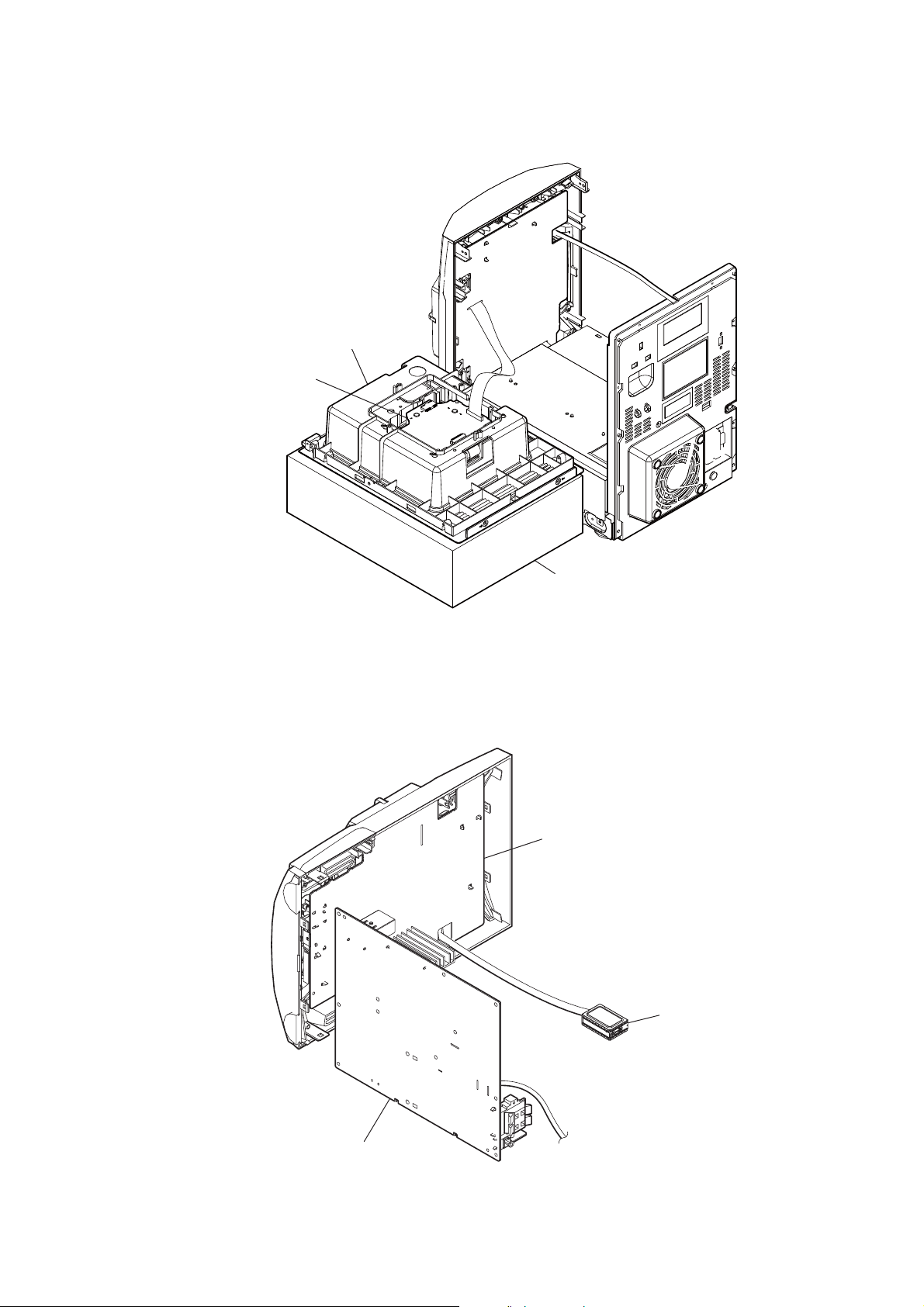
SERVICE POSITION OF CDM76
top panel section
BD76 board
HCD-EX600/EX700/EX900
SERVICE POSITION OF BOARDS
stand
PANEL board
tuner unit
AMP SMPS board
5
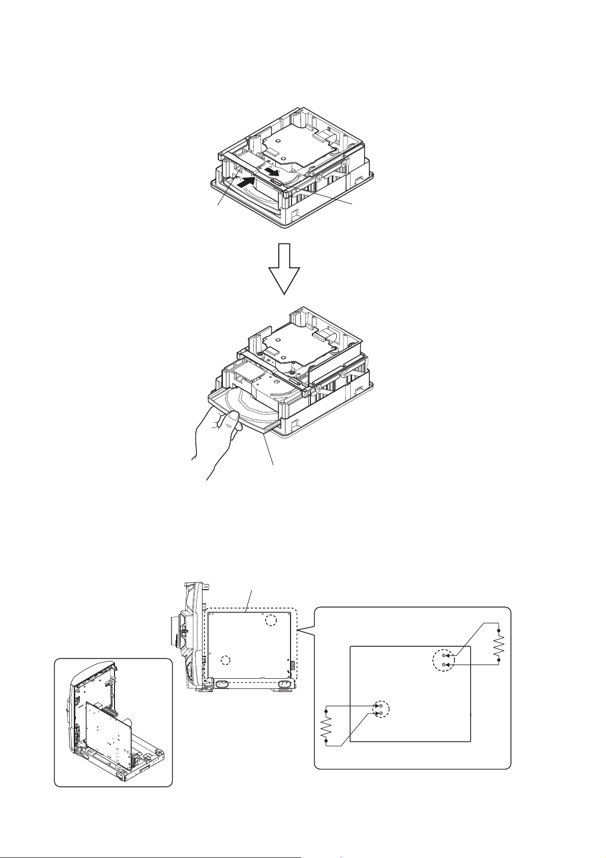
HCD-EX600/EX700/EX900
HOW TO OPEN THE TRAY WHEN POWER SWITCH TURN OFF
bracket
pin
Pull the tray by the hand.
CAPACITOR DISCHARGE FOR ELECTRIC SHOCK PREVENTION
AMP SMPS board
(Right side view)
6
In checking the AMP SMPS board, make a capacitor
discharge of C624 (EX600) or C625 (EX700) or C631
(EX900) and C914 for electrical shock prevention.
800 :/2 W
AMP SMPS board
C624 (EX600)
C625 (EX700)
C631 (EX900)
800 :/2 W
C914

PRECAUTION WHEN INSTALLING A NEW OP UNIT/
PRECAUTION BEFORE UNSOLDERING THE STATIC
ELECTRICITY PREVENTION SOLDER BRIDGE
HCD-EX600/EX700/EX900
When installing a new OP unit, be sure to connect the fl exible
printed circuit board fi rst of all before removing the static electric-
ity prevention solder bridge by unsoldering.
Remove the static electricity prevention solder bridge by unsoldering after the fl exible printed circuit board has already been con-
nected.
(Do not remove nor unsolder the solder bridge as long as the OP
unit is kept standalone.)
7
HCD-EX600/EX700/EX900
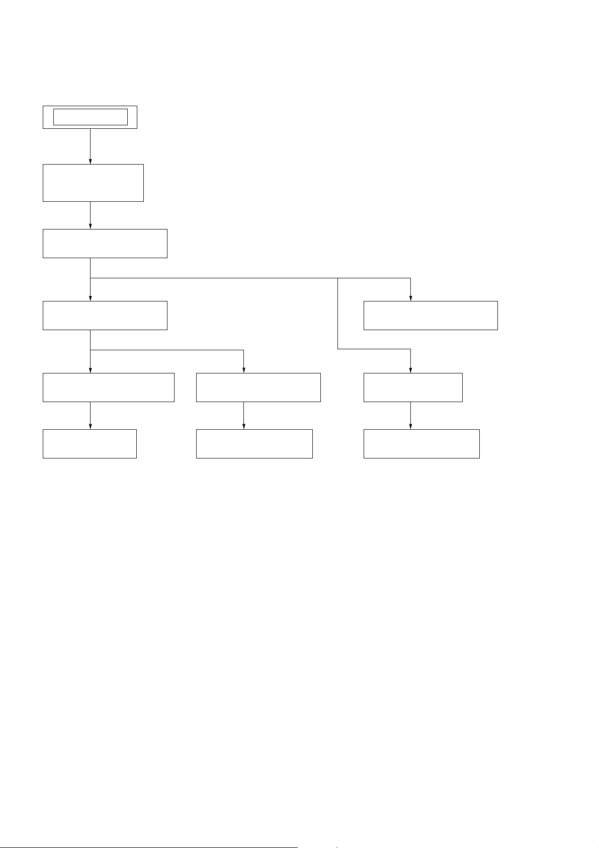
DISASSEMBLY
• This set can be disassembled in the order shown below.
SET
2-1. SIDE CASE (L),
SIDE CASE (R)
(Page 9)
2-2. TOP PANEL SECTION
(Page 9)
SECTION 2
2-3. SHIELD (POWER-PWB)
(Page 10)
2-4. FRONT PANEL SECTION
(Page 10)
2-7. KNOB (VOL)
(Page 13)
2-5. BACK PANEL SECTION
(Page 11)
2-6. AMP SMPS BOARD
(Page 12)
2-8. CD MECHANISM DECK
(Page 13)
2-9. BASE UNIT
(Page 14)
2-10. OPTICAL PICK-UP
(Page 14)
8

Note: Follow the disassembly procedure in the numerical order given.
2-1. SIDE CASE (L), SIDE CASE (R)
2 two screws
(case 3 TP2)
two claws
6 side case (L)
4
1 two screws
(case 3 TP2)
5
3 three screws
(+BVTP 3 u10)
HCD-EX600/EX700/EX900
8 two screws
two claws
qa
(case 3 TP2)
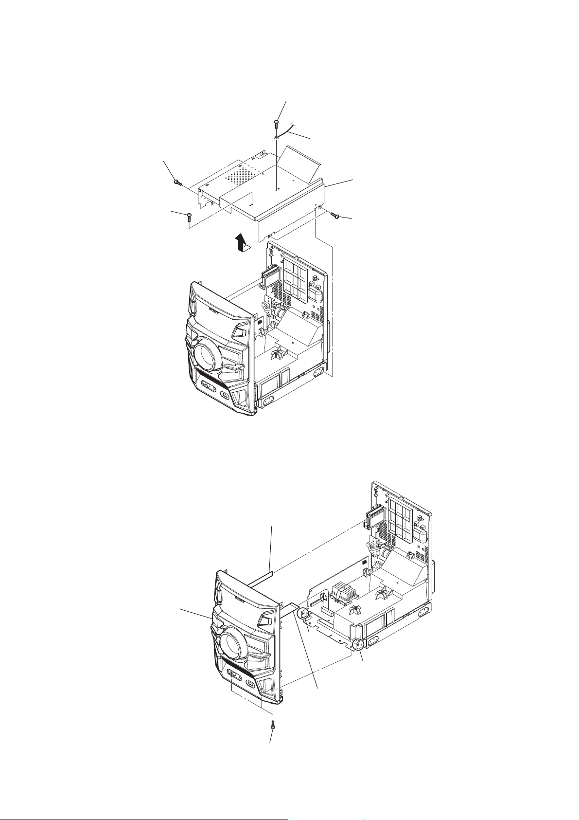
2-2. TOP PANEL SECTION
2 wire (flat type) (5 core)
(CN302)
4 screw
(+BVTP 3 u10)
7 two hooks
0
qs side case (R)
6
9 two screws
(+BVTP 3 u10)
7 two screws
(case 3 TP2)
5 two screws
(+BVTP 3 u10)
8 top panel section
1 wire (flat type) (21 core)
(CN401)
3 screw
(+BVTP 3 u10)
9
HCD-EX600/EX700/EX900
2-3. SHIELD (POWER-PWB)
1 screw
(+BVTP 3 u10)
4 two screws
(+BVTP 3 u10)
3 screw
(+BVTP 3 u10)
6
2 wire
7 shield (power-PWB)
5 two screws
(+BVTP 3 u10)
2-4. FRONT PANEL SECTION
4 front panel section
1 wire (flat type) (7 core)
(CN501)
claw
claw
2 wire (flat type) (21 core)
(CN600) (EX600/EX700)
wire (flat type) (23 core)
(CN600) (EX900)
10
3 three screws
(+BVTP 3 u10)

2-5. BACK PANEL SECTION
EX700/EX900
HCD-EX600/EX700/EX900
4 cover (power-PWB)
5 CN701 (3P) (EX700)
CN702 (6P) (EX900)
EX600
3 screw
(+BVTP 3 u10)
1 wire (flat type) (7 core)
(CN501)
2 screw
(+BVTP 3 u10)
7 two screws
(+BVTP 3 u10)
8 back panel section
6 CN901 (2P)
4 cover (power-PWB)
5 CN700 (3P)
3 screw
(+BVTP 3 u10)
1 wire (flat type) (7 core)
(CN501)
2 screw
(+BVTP 3 u10)
7 screw
(+BVTP 3 u10)
8 back panel section
6 CN901 (2P)
11

HCD-EX600/EX700/EX900
2-6. AMP SMPS BOARD
EX700/EX900
9 REGULATOR board
8 two screws
(+BVTP 3 u10)
6 three screws
(+BVTP 3 u10)
EX900
3 three screws
(+BVTP 3 u10)
2 screw
(+BVTP 3 u10)
1 wire (flat type) (21 core)
(CN600) (EX700)
wire (flat type) (23 core)
(CN600) (EX900)
EX600
6 three screws
(+BVTP 3 u10)
7 AMP SMPS board
4 bracket (SP08)
5 six screws
(+BVTP 3 u10)
0 AMP SMPS board
7
EX700
3 two screws
(+BVTP 3 u10)
2 screw
(+BVTP 3 u10)
4 bracket (SP08)
3 two screws
(+BVTP 3 u10)
2 screw
(+BVTP 3 u10)
1 wire (flat type) (21 core)
(CN600)
4 bracket (SP08)
5 six screws
(+BVTP 3 u10)
12

2-7. KNOB (VOL)
knob (VOL)
2
hole
HCD-EX600/EX700/EX900
front panel block
(back view)
Push the knob (VOL) by flat-head screwdriver.
1
2-8. CD MECHANISM DECK
4 two screws
(+P tapping (B2.6))
CD mechanism deck block
7
6 wire (flat type) (5 core)
2
top lid
5
4 two screws
(+P tapping (B2.6))
top panel
3
1 four screws
(+BVTP 3 u10)
13

HCD-EX600/EX700/EX900
2-9. BASE UNIT
2 two screws
(+BVTP 2.6 (3CR))
two stoppers (BU)
3
two insulators
6
base unit
7
two coil springs (insulator)
4
5
1 two floating screws
(+PTPWH M2.6)
two coil springs (insulator)
4
two insulators
6
top panel block
(bottom view)
2-10. OPTICAL PICK-UP
3 optical pick-up
Remove the four solders.
1
2 wire (flat type) (16 core)
(CN201)
4 BD76 board
14

SECTION 3
TEST MODE
HCD-EX600/EX700/EX900
COLD RESET
The cold reset clears all data including preset data stored in the
memory to initial conditions. Execute this mode when returning
the set to the customer.
Procedure:
1. In the standby status, press the [
] button to turn the power
?/1
on.
2. Press three buttons of [x], [FUNCTION] and [
] simultane-
?/1
ously.
3. When “RESET” appears, the set enters standby status.
PANEL TEST MODE
Enter The Panel Test Mode
Procedure:
1. In the standby status, press the [
] button to turn the power
?/1
on.
2. Press three buttons of [x], [OPTIONS] and [
] simultane-
?/1
ously.
3. When the panel test mode is activated, all LEDs and segments
of the liquid crystal display panel are all turned on.
Version Check
Procedure:
1. In the panel test mode (all LEDs and segments of the liquid
crystal display panel are turned on), press the [FUNCTION]
button.
2. On the liquid crystal display panel, date and version are displayed “xxxxVxxx”.
3. From this status, press the [u] button, and the destination and
model name are displayed.
4. To release from this mode, press three buttons of [x], [OPTIONS] and [
] simultaneously.
?/1
Key Test Mode
Procedure:
1. In the panel test mode (all LEDs and segments of the liquid
crystal display panel are turned on), press the [x] button.
2. The message “KEY0 0 0” displayed. Whenever any buttons
are pressed and the [VOLUME] control is turned, the value is
changed.
3. To release from this mode, press three buttons of [x], [OPTIONS] and [
] simultaneously.
?/1
CD TRAY LOCK
This mode is for the antitheft of CD disc in shop. (not for transport)
Procedure:
1. Press the [
] button to turn the power on.
?/1
2. Press the [FUNCTION] button to select CD function.
3. Insert a disc.
4. While pressing the [x] button for more 5 seconds.
5. The message “CHILD LOCK ON” is displayed and the disc
tray is locked. (Even if releasing from this mode, the disc tray
is still locked)
6. If press the [Z] button to eject the disc, the message “CHILD
LOCK” is displayed and can not eject the disc.
7. To release this lock, while pressing the [x] button for 5 seconds again.
8. The message “CHILD LOCK OFF” is displayed and the disc
tray is unlocked.
CD POWER MANAGE
This mode is for switch the CD power supply on/off. Even if this
state pulls out AC plug, it is held.
Procedure:
1. Press the [
] button to turn the power on.
?/1
2. Press the [FUNCTION] button to select CD function.
3. Press the [
] button again to turn the power off (clock
?/1
mode).
4. After pressing the [DISPLAY] button on the remote commander, while pressing the [x] button, press the [
?/1
] button.
5. It turns power on and display “CD/USB”, then display “PWR
ON” or “PWR OFF”.
CHANGE-OVER THE AM TUNING INTERVAL
The AM tuning interval can be changed over 9 kHz or 10 kHz.
Procedure:
1. Press the [
] button to turn the power on.
?/1
2. Press the [FUNCTION] button to select TUNER AM function.
3. Press the [
] button again to turn the power off (clock
?/1
mode).
4. After pressing the [DISPLAY] button on the remote commander, while pressing the [TUNING + M L] button,
press the [
?/1
] button.
5. It turns power on and display “9k STEP” or “10k STEP”, and
thus the tuning interval is changed over.
CD SHIP MODE
This mode can run the CD sled motor optionally. Use this mode,
for instance, when cleaning the optical pick-up.
Procedure:
1. Press the [
] button to turn the power on.
?/1
2. Confi rm there is no disc in tray.
3. Press the [FUNCTION] button to select CD function.
4. Press two buttons of [x] and [
] simultaneously.
?/1
5. Set to the CD ship mode (chucking on).
6. After blink “STANDBY”, “CHILD LOCK ON” is displayed,
disconnect the AC plug.
CD SHIP AND COLD RESET
Procedure:
1. Press the [
] button to turn the power on.
?/1
2. Confi rm there is no disc in tray.
3. Press the [FUNCTION] button to select CD function.
4. Press three buttons of [ENTER], [TUNING– l m] and
[
] simultaneously.
?/1
5. After blink “STANDBY”, “RESET” is displayed, disconnect
the AC plug.
15

HCD-EX600/EX700/EX900
SECTION 4
ELECTRICAL ADJUSTMENTS
CD SECTION
Note:
1. CD Block is basically constructed to operate without adjustment.
2. Use YEDS-18 disc (Part No. 3-702-101-01) unless otherwise indicated.
3. Use an oscilloscope with more than 10 MΩ impedance.
4. Clean the object lens by an applicator with neutral detergent when the
signal level is low than specifi ed value with the following checks.
5. Check the focus bias check when optical pick-up block is replaced.
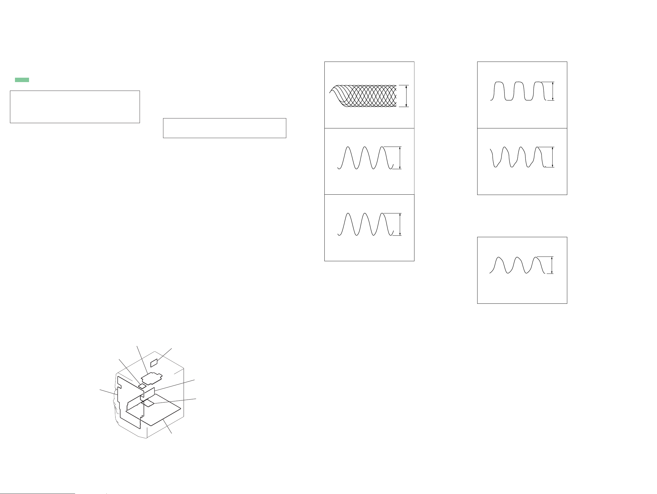
FOCUS BIAS CHECK
oscilloscope
(DC range)
BD76 board
CL102 (RFOUT)
CL117 (VREF)
Procedure:
1. Connect the oscilloscope to CL102 (RFOUT) and CL117
(VREF) on the BD76 board.
2. Press the [
] button to turn the power on, and press the
?/1
[FUNCTION] button to select CD function.
3. Set disc (YEDS-18) and press the [u] button to playback.
4. Confi rm that oscilloscope waveform is as shown in the fi gure
below (eye pattern).
A good eye pattern means that the diamond shape (◊) in the
center of the waveform can be clearly distinguished.
+
–
VOLT/DIV: 200 mV
TIME/DIV: 500 ns
TUNER SECTION
0 dB = 1 μV
FM AUTO STOP CHECK
signal
generator
set
+
75 :
–
Procedure:
1. Turn the power on.
2. Input the following signal from Signal Generator to FM antenna input directly.
Carrier frequency : A = 87.5 MHz, B = 98 MHz, C = 108 MHz
Deviation : 75 kHz
Modulation : 1 kHz
ANT input : 35 dBu (EMF)
Note: Please use 75 ohm “coaxial cable” to connect SG and the set. You
cannot use video cable for checking.
Please use SG whose output impedance is 75 ohm.
3. Set to FM tuner function and scan the input FM signal with
automatic scanning.
4. Confi rm that input Frequency of A, B and C detected and auto-
matic scanning stops.
Checking Location:
– BD76 Board (Side B) –
CL102
(RFOUT)
IC101
CL117
(VREF)
level:
1.1 ± 0.4 Vp-p
The stop of automatic scanning means “The station signal is received in good condition”.
16

5-1. BLOCK DIAGRAM –CD Section –
USB CONTROLLER
3
CN304
(USB)
D+
2
D-
1
4
VBUS+5V
X901
12MHz
38 UHD+
37 UHD-
CF1
6
CF2
7
SECTION 5
DIAGRAMS
IC901
DBGP0
DBGP1
DBGP2 25
URX1
UTX1 45
P71
RES 2
SO0 9
SI0
SCK0 11
P16 15
P23 32
SDAT
BCLK
LRCK
P22
P24
P70
HCD-EX600/EX700/EX900
8
23
24
44
47
10
26
27
28
31
33
46
DBGP0
DBGP1
DBGP2
TRESET
7
5
CN901
FLASH
( )
PROGRAMMING
9
5FKLVRPLWWHGGXHWRVDPHDV/FK
6LJQDOSDWK
: CD
: USB
OPTICAL PICK-UP BLOCK
(DA11MMVGP)
A
B
C
D
E
F
LD
MD
VREF
SP+
SP-
SL+
SL-
T+
T-
F+
F-
AUTOMATIC
POWER
CONTROL
Q201
FOCUS/TRACKING COIL DRIVE,
SLED/SPINDLE MOTOR DRIVE
IC301
VO1+2
VO1-
1
VO2+11
VO2-
12
VO3+18
VO3-
17
VO4+26
VO4-
27
IN1
IN2’
IN3’
IN4’
MUTE
3
9
20
24
7
CD-MP3 PROCESSOR
5 AIN
BIN
7
6 CIN
8 DIN
EIN
13
FIN
14
18 LDD
19
LDS
11 VREF
25 SPDO
24 SLDO
23 TDO
22 FDO
IC101
(Page 18)
TUNER/
AUDIO
SECTION
LCHO CD/USB-L76
RCHO R-CH78
STREQ
33
STCK 34
STDATA 35
PCMLRSY
62
63PCMBCK
64PCMDATA
65PCMREQ
43CE
44CL
45DI
46DO
LIMIT-SW
32
XOUT
72
XIN
73
47 O-CD-RST1
RESB
X101
16.934MHz
S001
(LIMIT)
A
O-USB-TXD93
I-USB-RXD94
O-USB-SLEEP
92
4
O-USB-RST
3
O-CD-CE
O-CD-CL
98
99
I-CD-DO
O-CD-DI
2
100
O-CD-M-MUTE
SYSTEM CONTROL
IC302 (1/3)
O-CD-ON 91
O-CD-M- 87
O-CD-M+
I-CD-OP/CL 18
DBGP0
DBGP1
DBGP2
I-RST 11
2
MOTOR
CONTROL
Q305
7
9
+3.3V
IC304
FIN
RIN
4
1
LOADING
MOTOR
DRIVE
IC303
1
VREF
OUT2
OUT1
DBGP0
DBGP1
DBGP2
RESET
+9V
88
95
96
97
AVDD3.3V
DVDD3.3V
2
4
2
3
5
( )
PROGRAMMING
1
CN301
FLASH
CD
MECHANISM
DECK
M+
M–
OPEN SW
CLOSE SW
I-HP/CD-SW
TUNER/
B
SECTION
(Page 18)
AUDIO
HCD-EX600/EX700/EX900
I-RST
DISPLAY/POWER
C
SECTION
(Page 19)
1717

HCD-EX600/EX700/EX900
5-2. BLOCK DIAGRAM –TUNER/AUDIO Section –
J301
-1
L
DVD/PC IN
CN502
ANTENNA
FM/AM
-2
R
3
FM
2
AM
1
AM
1
: FM
: AM
: CD
: DVD
2
+3.3V REG
9V
R-FK LV RPLWWHG GXH WR VDPH DV L-FK.
SLJQDO SDWK
R-CH
FL501
BAND-PASS
FILTER
L501
IC501
CD SECTION
(Page 17)
AM/FM-DET,OSC,MIX,PLL,IF AMP
FRF1
4
ARF1
6
ARF2
7
+3.3V(TU)
5
IC502
A
LOUT
ROUT
I2C/RDSI
8CK10DA13
CD/USB-L
15
14
X1
18
X2
19
R-CH
R-CH
R-CH R-CH
X501
32.768kHz
INPUT FUNCTION SELECTOR
CD/USB-L
8
CD/USB-R
7
PC-IN-L
10
PC-IN-R
9
TUNER-L
6
TUNER-R
5
SCLK
27
SDATA
28
ISYSTEM CONTROL
I2C-FUNC-DATA
6
I2C-FUNC-CLK
7
I-RDSI
41
I2C-TU-CLK
9
I2C-TU-DATA
8
IC306
IC302 (2/3)
OUT-L
OUT-R
SEL-L
SEL-R
I-SIGNAL-LEVEL
I-LED-LEVEL
I-VACS
O-HP-MUTE
O-SW-MUTE
O-FR-RELAY
O-AMP-RST
21
25
11
12
DISPLAY/
POWER
SECTION
(Page 19)
21
22
23
36
32
31
33
R-CH
VACS/SIGNAL LEVEL
CONTROL
IC305
3 1
5 7
PROTECT-F
D
D324
D319
HEADPHONE
SUBWOOFER
AMP
Q312-315
SUBWOOFER
MUTE
Q311,316,317
PRE AMP
IC600 (EX600)
IC600 (EX700)
6 7
AMP
IC308
8
VCC
5 7
MUTE
CONTROL
Q321,324
PRE AMP
IC600
5 7
2
PRE AMP
IC601
5 10
7
PRE AMP
IC601 (EX600)
IC601 (EX700)
6 7
R-CH
R-CH
+8.3V REG
Q319
MUTE
Q325
4
51
11
R-CH
SPEAKER RELAY
DRIVER
Q705
5
4
10
11
INPUT_A
INPUT_B
INPUT_C
INPUT_D
INPUT_B
INPUT_B
INPUT_C
INPUT_D
+9V
CD SECTION
(Page 17)
R-CH
POWER AMP
IC800
RESET
2 5
POWER AMP
IC800 (EX600)
IC800 (EX700)
RESET15SD
2
OUT_A
OUT_A
OUT_B
OUT_B
OUT_C
OUT_C
OUT_D
OUT_D
SD
DC DETECT
Q706
OUT_B
OUT_B
OUT_A
OUT_A
OUT_C
OUT_C
OUT_D
OUT_D
DC DETECT
Q705
R-CH
I-HP/CD-SW
B
52
53
44
45
36
37
28
29
OVERLOAD
DETECT
Q604-607,
609,610
44
45
52
53
36
37
28
29
D601
OVERLOAD
DETECT
Q604-607
TB601
TB600
RY600
PHONES
+
SUBWOOFER
–
IMPEDANCE USE 8ȍ
+
L
–
IMPEDANCE USE 3ȍ
+
R
–
TB600
4
+
L
3
–
IMPEDANCE USE 4ȍ
2
+
R
1
–
J302
EX900
SPEAKERS
EX600/EX700
SPEAKERS
HCD-EX600/EX700/EX900
O-FAN-LOW-SPEED
I-PROTECT-S
FAN MOTOR CONTROL
30
35
Q706,707,712 (EX600)
Q608,706,707 (EX700)
Q707,708,712 (EX900)
DC DETECT
Q711
D704
+13V
+9V
M+7V
FAN MOTOR
REG
Q708 (EX600/EX700)
Q709 (EX900)
FAN MOTOR
DETECT
Q709 (EX600/EX700)
Q710 (EX900)
+
FAN701
DC FAN
–
1818

5-3. BLOCK DIAGRAM –DISPLAY/POWER Section –
SYSTEM CONTROL
IC302 (3/3)
45
SEG0
I
53
56
SEG32
I
79
COM3
83
I
COM0
86
26
I-KEY0
I-KEY1
25
I-KEY2
24
29
I-RMC
12
SUB CLOCK
13
SUB CLOCK
15
MAIN CLOCK
16
MAIN CLOCK
43
O-LCD-LED
5
O-DIMMER
10
O-VOL-LED
28
I-AC-CUT
I
I
D301,302
LCD BACK
LIGHT
D303,305,307,
309,310
+3.3V(A)
E+4V
RESET
2
VDD1OUT
S301,303–309,
312–316
KEY MATRIX
REMOTE CONTROL
SIGNAL RECEIVER
IC307
IC301
ND301
LIQUID
CRYSTAL
DISPLAY
PANEL
LED
DRIVER
Q303
+5.7V REG
Q301
DIMMER
CONTROL
Q302
LED
DRIVER
Q304
CD SECTION
(Page 17)
3
RESET
Q310
I-RST
C
X301
32.768kHz
X302
20MHz
+9V
I-PROTECT-F
O-MAIN-ON
I-V2-MONI
O-STBY-SW
O-SUB-ON
O-VBUS-ON
I-VBUS-OCP
HCD-EX600/EX700/EX900
T901
DC-DC CONVERTER
RECT
TRANSFORMER (MAIN)
D943
PVDD
OVER CURRENT
27
PROTECT-F
D
TUNER/AUDIO
SECTION
(Page 18)
+12V
EX700/EX900
37
+12V
34
42
38
39
40
DETECT
Q600,601 (EX700)
Q602,603 (EX900)
POWER
CONTROL
Q934,935
POWER
CONTROL
Q933
+12V REG
IC602 (EX700)
IC602 (EX900)
4
VIN
VOUT
VCONT
1
POWER
CONTROL
Q602,603 (EX700)
Q600,601 (EX900)
POWER
CONTROL
Q970
VOLTAGE DETECT
IC604
OUT1VDD
+12V REG
3 1
IC602
1
OUT
VDD
+3.3V(C)
V2
2
PVDD
2
VOLTAGE DETECT
IC603 (EX600)
IC603 (EX700)
IC603 (EX900)
2
V2
STANDBY
CONTROL
Q308,309
V2
POWER
CONTROL
Q601,602
4
VREF
K
3
+3.3V(A)
VREF
K
VREF
4
3
VOLTAGE
DETECT
IC932 (EX700)
IC932 (EX900)
PH930
ISOLATION
PH931
ISOLATION
4
K
IC966 (EX700)
IC966 (EX900)
3
PH965
ISOLATION
F931
VOLTAGE
DETECT
IC932
PH930
ISOLATION
CONTROL
Q702,703
RECT
D981
VOLTAGE
DETECT
RECT
D967
RECT
D965
PVDD
+9V REG
IC701 (EX600)
IC701 (EX700)
IC701 (EX900)
POWER
D941
D937
T903
DC-DC CONVERTER
TRANSFORMER (SUB)
+19V REG (EX700)
D970
+22V REG (EX900)
T901
DC-DC CONVERTER
TRANSFORMER
D940
D934
3
+9V
VBUS+5V
VOLTAGE
DETECT
Q930
Q965
D972
LIMITER
+3.3V(B)
1
VBUS OCP
POWER
ON/OFF
Q932
D967
+22V
Q930
E+4V
DETECT
Q704
+13V
M+7V
D315
1
D
VCC
4
6
FB
OCP/BD
7
1
D
3
VCC/OVP
BD
6
FB/OLP
5
D
1
DC-DC
CONVERTER
VCC/OVP
3
BD
6
FB/OLP
5
DC-DC
CONVERTER
IC931 (EX700)
IC931 (EX900)
DC-DC
CONVERTER
IC965 (EX700)
IC965 (EX900)
IC930
VOUT4VIN
CONTROL
4
VOUT
2
SW
VBUS+5V REG
IC703 (EX600)
IC703 (EX700)
IC703 (EX900)
POWER
Q700,701
1
VC
5
SS
EX600
VIN
IN
+4V REG
IC700 (EX600)
IC700 (EX700)
IC700 (EX900)
2
+7V REG
IC702 (EX600)
IC702 (EX700)
IC702 (EX900)
2
1
RECT
D901 (EX700)
D902 (EX600/EX900)
TH901 (EX600)
TH902 (EX700/EX900)
EX700/
EX900
EX600
PVDD
L901,902 (EX700/EX900)
L903,904 (EX600)
F901
AC IN ~
V2
HCD-EX600/EX700/EX900
1919
HCD-EX600/EX700/EX900
THIS NOTE IS COMMON FOR PRINTED WIRING BOARDS AND SCHEMATIC DIAGRAMS.
(In addition to this, the necessary note is printed in each block.)
For Printed Wiring Boards.
Note:
• X : Parts extracted from the component side.
• : Pattern from the side which enables seeing.
(The other layers’ patterns are not indicated.)
Caution:
Pattern face side:
(SIDE B)
Parts face side:
(SIDE A)
• Abbreviation
RU : Russian model
Parts on the pattern face side seen
from the pattern face are indicated.
Parts on the parts face side seen from
the parts face are indicated.
For Schematic Diagrams.
Note:
• All capacitors are in μF unless otherwise noted. (p: pF) 50
WV or less are not indicated except for electrolytics and
tantalums.
• All resistors are in Ω and 1/4 W or less unless otherwise
specifi ed.
• f : Internal component.
• 2 : Nonfl ammable resistor.
• C : Panel designation.
Note: The components identifi ed by mark 0 or dotted
line with mark 0 are critical for safety.
Replace only with part number specifi ed.
• A : B+ Line.
• B : B– Line.
• Voltages and waveforms are dc with respect to ground
under no-signal (detuned) conditions.
– BD76 Board –
no mark : CD PLAY
– Other Boards –
no mark : TUNER (FM/AM)
* : Impossible to measure
• Voltages are taken with VOM (Input impedance 10 MΩ).
Voltage variations may be noted due to normal production
tolerances.
• Waveforms are taken with a oscilloscope.
Voltage variations may be noted due to normal production
tolerances.
• Circled numbers refer to waveforms.
• Signal path.
F : TUNER (FM)
f : TUNER (AM)
J : CD
E : USB
q : DVD/PC IN
• Abbreviation
RU : Russian model
• Waveforms
– BD76 Board –
1 IC101 2 (RFOUT)
(CD play mode)
200 mV/DIV, 500 nsec/DIV
2 IC101 us (XOUT)
16.934 MHz
1 V/DIV, 20 nsec/DIV
3 IC901 7 (CF2)
12 MHz
1 V/DIV, 20 nsec/DIV
0.6 to 1.5 Vp-p
2.6 Vp-p
3.1 Vp-p
– PANEL Board –
1 IC302 qd (Sub Clock)
32.768 kHz
1 V/DIV, 10 Psec/DIV
2 IC302 qh (Main Clock)
20 MHz
1 V/DIV, 50 nsec/DIV
– TUNER Board –
1 IC502 ql (X2)
32.768 kHz
3.3 Vp-p
2.9 Vp-p
0.6 Vp-p
• Circuit Boards Location
PANEL board
BD76 board
LOADING board
200 mV/DIV, 5 Psec/DIV
TUNER board
REGULATOR board
(EX700/EX900)
EFX-MODULE board
AMP SMPS board
HCD-EX600/EX700/EX900
2020

HCD-EX600/EX700/EX900
5-4. PRINTED WIRING BOARD – CD Section –
1
A
B
234567891011121314
BD76 BOARD (SIDE A) BD76 BOARD (SIDE B)
R304
C301
R305
C303
C304
C302
C
D
E
F
R402
C402
R901
R401
C401
C953
C902 C903
X901
R129
C416
R904
C417
C129
C124
R415
R414
C415
G
• See page 20 for Circuit Boards Location.
C127
CP201
R201
R202
C201
E C B
Q201
C131
C209
C206
R203
C208
• : Uses unleaded solder.
28
22 21 15
30
IC301
781
29
S001
(LIMIT)
CL410
R411
CL411
CL413
C905
R905
C907 R907
CL908
C904
R906
C906
12
13
R908
C909
24
R909
25
R911
R913
R902
R914
CL905
CL907
CL909
91
82
CL904
CN901
FLASH
PROGRAMMING
R903
IC901
CL903
R303
CL902
M402
(SLED)
CL408
CL409
C901
1
48
37
36
CL901
14
+
CL401
M
CL402
–
CL404
R413
CL405
R412
CL406
CN401
R924
R923
R922
C405
C951C952
C955
R955
CL416
R403
R953
R951R952
R954
20
2
CL419
21
CL414
1
CL420
CL421
1-883-378-
CL403
CL407
CL418
CL415
CL417
(11)
PANEL
BOARD
A
CN303
(Page 24)
11
CL118
CL115
–
R301
R302
S001
R416
C418
CL114
CL113
CL112
R124
R123
R122
CL108
C113
C126
C123
C202
CL111
CL110
CL412
CL109
R118
R121
R409
R408
R407
R120
R406
C125
CL107
R117
CL119
C204
CL206
CL214
CL213
C908
R910
R912
CL906
+
CL203
CL204
SL302
CL201
C116
CL209
CL210
C119
CL117
C207
CL208
CL211
C107
CL207
C117
C102
C103
R102
CL205
CL212
C133
R104
R105
R108
R111
CL202
R109
SL304
R107
C104
C105
SL201
CL102
R112
SL303
R417
C132
80 61
1
20
21 40
CL106
R113 R114
C111
C112
X101
R126
C121
R116
R101
C101
CL101
R103
R106
C118
C106
C108
CL104
C120
CL105
C110
IC101
CL116
C407
C406
CL120
C130
(SPINDLE)
SL301
CL121
C128
C122
R405
R404
M
M401
60
41
11
1-883-378-
(11)
116
CN201
OPTICAL
PICK-UP
BLOCK
(DA11MMVGP)
HCD-EX600/EX700/EX900
2121

HCD-EX600/EX700/EX900
5-5. SCHEMATIC DIAGRAM – CD Section (1/2) –
BD76 BOARD (1/2)
A
CN201
16P
16
VREF
15
VCC
E
GND
D
A
B
C
F
LD
VR
MD
F+
TT+
F-
B
C
OPTICAL
PICK-UP
BLOCK
(DA11MMVGP)
M401
(SPINDLE)
1234
D
M402
(SLED)
MM
E
F
CL212
14
CL211
13
CL210
12
CL209
11
CL208
10
CL207
9
8
CL206
7
6
CL205
5
CL204
4
CL203
3
CL202
2
CL201
1
SP+
SP-
SL+
SL-
• See page 20 for Waveforms. • See page 44 for IC Block Diagrams.
72 9
X101
IC B/D
1.7
1
1.7
2
1.6
3
1.7
4
1.7
5
1.7
6
1.7
7
1.7
8
1.7
9
10
3.3
11
0.8
12
1.7
13
1.7
14
3.3
15
1.7
16
1.6
17
3.3
18
0
19
20
R305
8.2k
C201
0.1
C202 1
C204 1
AUTOMATIC
POWER CONTROL
C209
0.1
CL213
CL214
Q201
2SA2119K
R304
10k
643
C133
0.1
R201
1
R202
3.3
2.2
3.3
1.6
C208
1000p
R108
1k
R109
1k
R112
0R103
0R104
0R105
0R106
C106
0
SL304
SL303
C206
R203
SL201
C207
C117
100
1
0
0.047
16V
R102
10k
0.01C102
0.1C103
0.1C104
C119
16V100
0.01C1053300p
0.1C107
0.1C118
68kR107
22kR111
16.934MHz
330R101
CL101
CL102
4700pC101
CL103
CL117
CL104
0.01C108
85
C116
100
16V
R126
0
1.7
SLCO
LRVSS
EFMIN
RFOUT
1
LPF
PHLPF
AIN
CIN
BIN
DIN
SLCISET
RFMON
VREF
JITTC
EIN
FIN
PCNCNT
TE
TEIN
LDD
LDS
AVSS
AVDD
FDO
21 22 23 24 25 26 27 28 29 30 31 32 33 34 35 36 37 38 39 40
3.3
1.7
1.7
RCHO
TDO
1.7
1.7
1.7
LCHO
LRREF
SLDO
SPDO
1.7
1.701.8
C132
0.1
C131
0.1
1.5
3.3
3.3
XIN
XVDD
LRVDD
LC786950T-US-H
CD-MP3 PROCESSOR
VVSS1
PDOUT1
PDOUT0
CL105
CL106
680R113
680R114
0.22C110
0.022C111
1.7
XOUT
2
IC101
PCKIST
1.1
0.1C112
C130
CL116
XVSS
CONT4
IC101
VVDD1
CONT5(M-MUTE)
3.3
CL120
68kR116
0.1
CL121
3.3
DOUT
LIMIT-SW(CONT3)
000
3.3
CL119
S001
(LIMIT)
CL118
DVSS
DVDD
STREQ(DEFECT)
STCK(FSEQ)
R117
10k
C122
0.1
C128
1
DVDD15
PCMREQ
STDATA(C2F)
DVDD
3.3
C129
100
16V
3.3
00001.6
6162636465666768697071727374757677787980
DVDD
PCMBCK
PCMDATA
C2F(LRSY)
PCMLRSY
FSEQ(DATACK)
DEFECT(DATA)
AD_DATA(STDATA)
AD_BCK(STCK)
AD_LRCK(STREQ)
DVSS
DVDD15
VVDD3
VVSS3
1.6
3.3
C123
1
C124
100
16V
CL107
C127
0.1
TEST1
TEST0
CONT0
CONT1
CONT2
INTB1
INTB0
RESB
DVSS
DVDD
C407
111
C418
100p
R416 100
R417
CL115
60
CL114
59
CL113
58
57
56
55
54
53
52
51
50
49
48
47
46
DO
45
DI
44
CL
43
CE
42
41
47p
0
0
0
3.3
3.3
3.3
3.3
0
3.3
R405 100
R404 100
C406
47p
CL112
CL111
CL110
CL109
CL108
R121
10k
C125
10kR124
10kR123
10kR122
C126
0.1
0.1
0
100R409
R120
C113
10k
0.1
1210
1
2
3
4
5
6
7
8
9
10
100R411
100R118
100R408
100R407
100R406
11
12
13
14
15
16
17
18
19
20
21
22
BD76
BOARD
1
(Page 23)
(2/2)
G
H
I
HCD-EX600/EX700/EX900
SPSP+
SL+
SL-
C304
0.1
C302
C303
0.1
0.1
3.2
3.2
1.7
3.3
VO4+
IN1
R301
5.6k
IN4
RESET
IN4’
REGB
BIAS
REGOUT
7
7
VCC
MUTE
0
R302
33k
28 27 26 25 24 23 22 21 20 19 18 17 16 15
GND
VO4-
IC301
BA5826HFP-E2
VO1-
VO1+
3.2
3.2
1.7
7
1.7
30
IN3’
VCC
GND
GND
IN2’
GND
1.7
R303
12k
C120
0.1
C121
0.1
C301
220
3.2
3.2
IN3
VO3-
OPIN
VO3+
RESETt
IN2
VO2+
VO2-
GND
OPOUT
141312111098765432129
3.2
3.2
SL302
SL301
IC B/D
IC301
FOCUS/TRACKING COIL DRIVE,
SPINDLE/SLED MOTOR DRIVE
10V
2222
 Loading...