

Sony HCD-EP707 Service Manual

HCD-EP707
SERVICE MANUAL
Ver 1.0 2002.06
HCD-EP707 is the amplifier, CD
player , tape deck and tuner section
in CMT-EP707.
CD
Section
TAPE
Section
SPECIFICATIONS
US Model
Canadian Model
AEP Model
UK Model
Austr alian Model
Model Name Using Similar Mechanism NEW
CD Mechanism Type CMCJ-0132
Model Name Using Similar Mechanism HCD-EP505
Tape T ransport Mechanism T ype CRL4349
AUDIO POWER SPECIFICATIONS:
(U.S.A. model only)
POWER OUTPUT AND TOTAL
HARMONIC DISTORTION:
with 4 Ω loads both channels driven, from 120
- 10,000 Hz; rates 15 W per channel minimum
RMS power, with no more than 10% total
harmonic distortion from 250 mW to rated
output.
Amplifier section
Canadian model:
Continuous RMS power output (reference)
European model:
DIN power output (rated) 12 + 12 W
Continuous RMS power output (reference)
Music power output (reference)
Other model:
The following measured at AC 230 V or AC 120 V,
50/60 Hz
DIN power output (rated) 12 + 12 W
Continuous RMS power output (reference)
Inputs
MD IN (phono jacks): voltage 450 mV,
Outputs
PHONES: Accepts headphones of
(stereo mini jack) 8 Ω or more
SPEAKER: Accepts impedance of 8 to
15 + 15 W
(4 Ω at 1 kHz, 10% THD)
(4 Ω at 1 kHz, DIN)
15 + 15 W
(4 Ω at 1 kHz, 10% THD)
38 + 38 W
(4 Ω at 1 kHz, DIN)
15 + 15 W
(4 Ω at 1 kHz, 10% THD)
impedance 47 kilohms
16 Ω
CD player section
System Compact disc and digital
Laser Semiconductor laser
Frequency response 20 Hz - 20 kHz (±0.5 dB)
OPTICAL DIGITAL OUT
(Square optical connector jack, rear panel)
Wavelength 660 nm
Tape player section
Recording system 4-track 2-channel stereo
Frequency response 50 - 13 000 Hz (±3 dB),
Tuner section
FM stereo, FM/AM superheterodyne tuner
FM tuner section
Tuning range 87.5 - 108.0 MHz
Antenna FM lead antenna
Antenna terminal (Except for European model)
Intermediate frequency 10.7 MHz
AM tuner section
Tuning range
Pan-American model: 530 - 1 710 kHz
European model: 531 -1 602 kHz
audio system
(λ=780 nm)
Emission duration:
continuous
using Sony TYPE I
cassette
75 Ω coaxial
(with the interval set at
10 kHz)
531 - 1 710 kHz
(with the interval set at
9 kHz)
(with the interval set at
9 kHz)
Other models: 531 - 1 602 kHz
Antenna AM loop antenna
Intermediate frequency 450 kHz
General
Power requirements
North American model : 120 V AC, 60 Hz
Other models: 230 V AC, 50/60 Hz
Power consumption
European model: 38 W
Other models: 38 W
Dimensions (w/h/d):
Mass: Approx. 5.0 kg
Supplied accessories: AM loop antenna (1)
Design and specifications are subject to change
without notice.
(with the interval set at
9 kHz)
530 - 1 710 kHz
(with the interval set at
10 kHz)
0.5 W (in the standby
mode)
Approx. 180 × 246 × 335 mm
Remote Commander (1)
Batteries (2)
FM lead antenna (1)
(Except for European
model)
9-874-043-01 Sony Corporation
2002F0500-1 Home Audio Company
C 2002.06 Published by Sony Engineering Corporation
COMPACT DISC DECK RECEIVER
HCD-EP707
r
Notes on chip component replacement
•Never reuse a disconnected chip component.
• Notice that the minus side of a tantalum capacitor may be damaged by heat.
Flexible Circuit Board Repairing
•Keep the temperature of the soldering iron around 270 ˚C during repairing.
• Do not touch the soldering iron on the same conductor of the
circuit board (within 3 times).
• Be careful not to apply force on the conductor when soldering
or unsoldering.
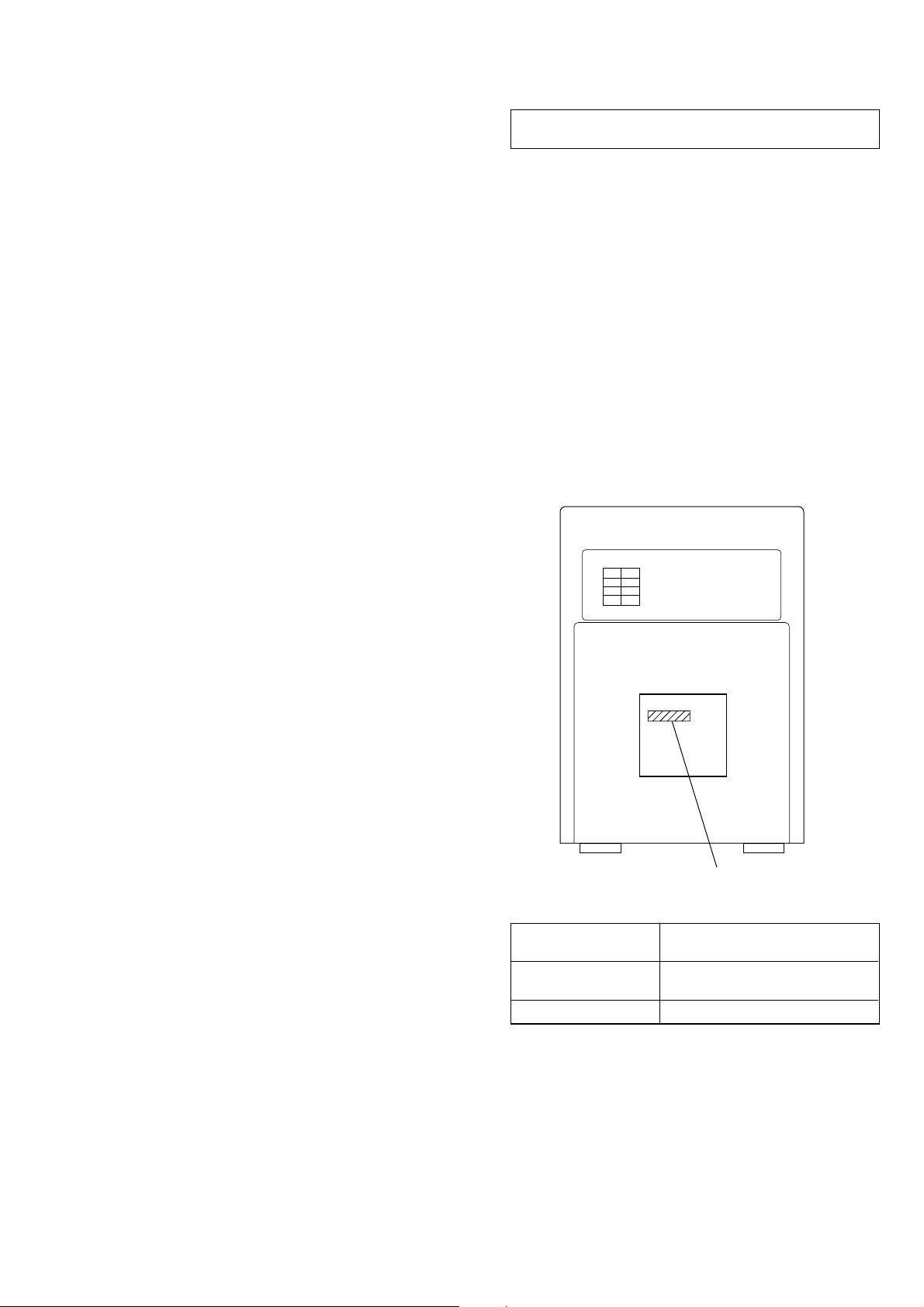
This appliance is classified as a CLASS 1 LASER product.
The CLASS 1 LASER PRODUCT MARKING is located on
the bottom.
CAUTION
Use of controls or adjustments or performance of procedures
other than those specified herein may result in hazardous radiation exposure.
SAFETY CHECK-OUT
After correcting the original service problem, perform the following safety check before releasing the set to the customer:
Check the antenna terminals, metal trim, “metallized” knobs,
screws, and all other exposed metal parts for AC leakage.
Check leakage as described below.
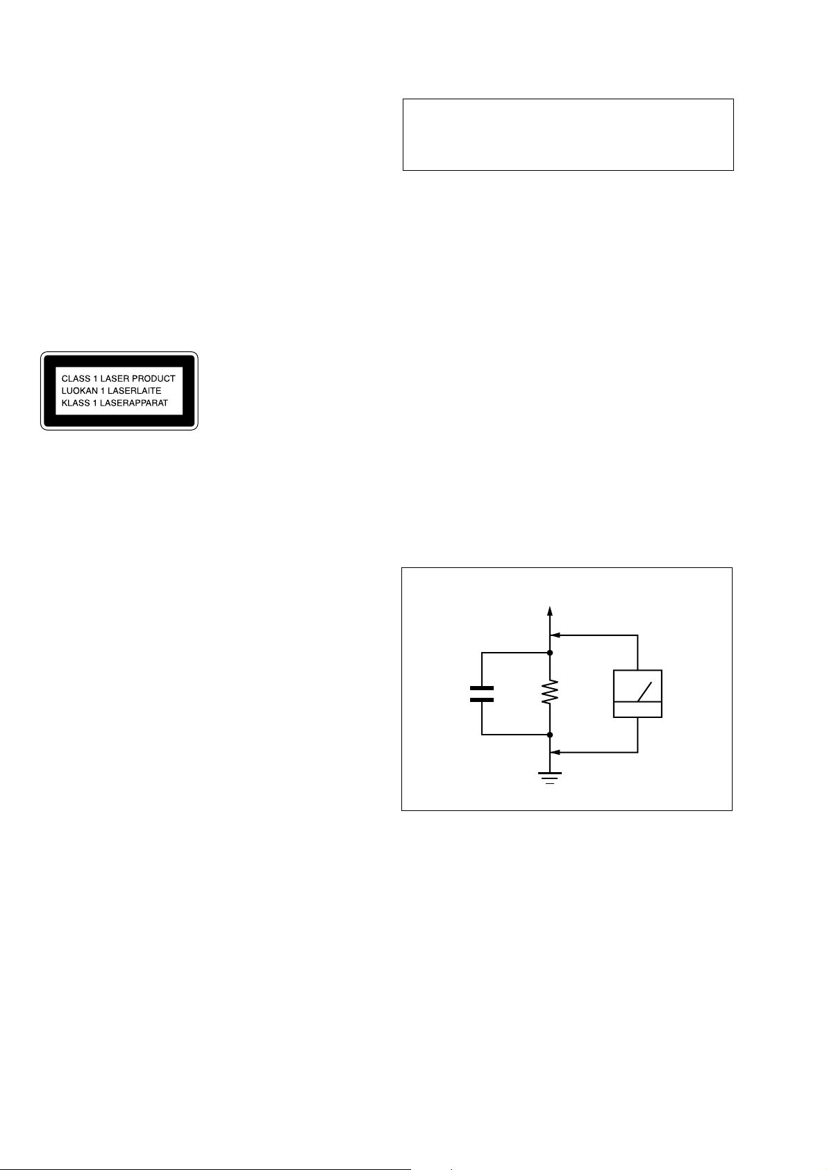
LEAKAGE TEST
The AC leakage from any exposed metal part to earth ground and
from all exposed metal parts to any exposed metal part having a
return to chassis, must not exceed 0.5 mA (500 microamperes.).
Leakage current can be measured by any one of three methods.
1. A commercial leakage tester, such as the Simpson 229 or RCA
WT -540A. Follo w the manufacturers’ instructions to use these
instruments.
2. A battery-operated AC milliammeter. The Data Precision 245
digital multimeter is suitable for this job.
3. Measuring the voltage drop across a resistor by means of a
VOM or battery-operated AC voltmeter. The “limit” indication is 0.75 V, so analog meters must have an accurate lowvoltage scale. The Simpson 250 and Sanwa SH-63T rd are examples of a passive VOM that is suitable. Nearly all battery
operated digital multimeters that have a 2 V A C range are suitable. (See Fig. A)
SAFETY-RELATED COMPONENT WARNING!!
COMPONENTS IDENTIFIED BY MARK 0 OR DOTTED
LINE WITH MARK 0 ON THE SCHEMATIC DIA GRAMS
AND IN THE PARTS LIST ARE CRITICAL TO SAFE
OPERATION. REPLACE THESE COMPONENTS WITH
SONY PARTS WHOSE PART NUMBERS APPEAR AS
SHOWN IN THIS MANUAL OR IN SUPPLEMENTS PUBLISHED BY SONY.
To Exposed Metal
Parts on Set
AC
1.5 k
0.15 µF
Fig. A. Using an AC voltmeter to check AC leakage.
ATTENTION AU COMPOSANT AYANT RAPPORT
À LA SÉCURITÉ!
LES COMPOSANTS IDENTIFIÉS P AR UNE MARQUE 0
SUR LES DIAGRAMMES SCHÉMATIQUES ET LA LISTE
DES PIÈCES SONT CRITIQUES POUR LA SÉCURITÉ
DE FONCTIONNEMENT. NE REMPLACER CES COMPOSANTS QUE PAR DES PIÈCES SONY DONT LES
NUMÉROS SONT DONNÉS DANS CE MANUEL OU
DANS LES SUPPLÉMENTS PUBLIÉS PAR SONY.
Ω
Earth Ground
voltmete
(0.75 V)
2
HCD-EP707
SECTION 1
SERVICING NOTES
TABLE OF CONTENTS
1. SERVICING NOTES ................................................ 3
2. GENERAL ................................................................... 4
3. DISASSEMBLY
3-1. Disassembly Flow ........................................................... 6
3-2. Side (Panel) ..................................................................... 7
3-3. Top Cabinet Section ........................................................ 7
3-4. Tape Mechanism Deck (CRL4349) ................................ 8
3-5. Front Panel Section ......................................................... 8
3-6. MAIN Board ................................................................... 9
3-7. CD Mechanism Deck (CMCJ-0132) .............................. 9
3-8. REGULATOR Board ...................................................... 10
3-9. POWER AMP Board ....................................................... 10
3-10. Cover ............................................................................... 11
3-11. Drawer ............................................................................. 11
3-12. Optical Block, Belt.......................................................... 12
4. ELECTRICAL ADJUSTMENTS......................... 13
5. DIAGRAMS
5-1. Block Diagram – TUNER Section – ............................. 14
5-2. Block Diagram – TAPE DECK Section –..................... 15
5-3. Block Diagram – MAIN Section – ................................ 16
5-4. Block Diagram
– DISPLAY/POWER SUPPLY Section – ...................... 17
5-5. Note for Printed Wiring Boards and
Schematic Diagrams ....................................................... 18
5-6. Printed Wiring Boards – MAIN Section – .................... 19
5-7. Schematic Diagram – MAIN Section (1/2) – ................ 20
5-8. Schematic Diagram – MAIN Section (2/2) – ................ 21
5-9. Printed Wiring Boards – POWER AMP Section – ...... 22
5-10. Schematic Diagram – POWER AMP Section –............ 23
5-11. Printed Wiring Boards – DISPLAY Section – .............. 24
5-12. Schematic Diagram – DISPLAY Section –................... 25
5-13. Printed Wiring Boards – REGULATOR Section – ....... 26
5-14. Schematic Diagram – REGULATOR Section – ........... 27
5-15. IC Pin Function Description ........................................... 29
NOTES ON HANDLING THE OPTICAL PICK-UP
BLOCK OR BASE UNIT
The laser diode in the optical pick-up block may suffer electrostatic break-down because of the potential difference generated
by the charged electrostatic load, etc. on clothing and the human
body.
During repair, pay attention to electrostatic break-down and also
use the procedure in the printed matter which is included in the
repair parts.
The flexible board is easily damaged and should be handled with
care.
NOTES ON LASER DIODE EMISSION CHECK
The laser beam on this model is concentrated so as to be focused
on the disc reflective surface by the objective lens in the optical
pick-up block. Therefore, when checking the laser diode emission, observe from more than 30 cm away from the objective lens.
• MODEL IDENTIFICATION
– Rear View –
6. EXPLODED VIEWS
6-1. Panel Section ................................................................... 31
6-2. Front Panel Section ......................................................... 32
6-3. Top Cabinet Section ........................................................ 33
6-4. Chassis Section ............................................................... 34
6-5. CD Section ...................................................................... 35
7. ELECTRICAL PARTS LIST ............................... 36
Model
US and Canadian
models
Other models
Power Voltage Indication
Power Voltage
Indication
AC: 120 V 60 Hz 38 W
AC: 230 V - 50/60 Hz 38 W
3
HCD-EP707
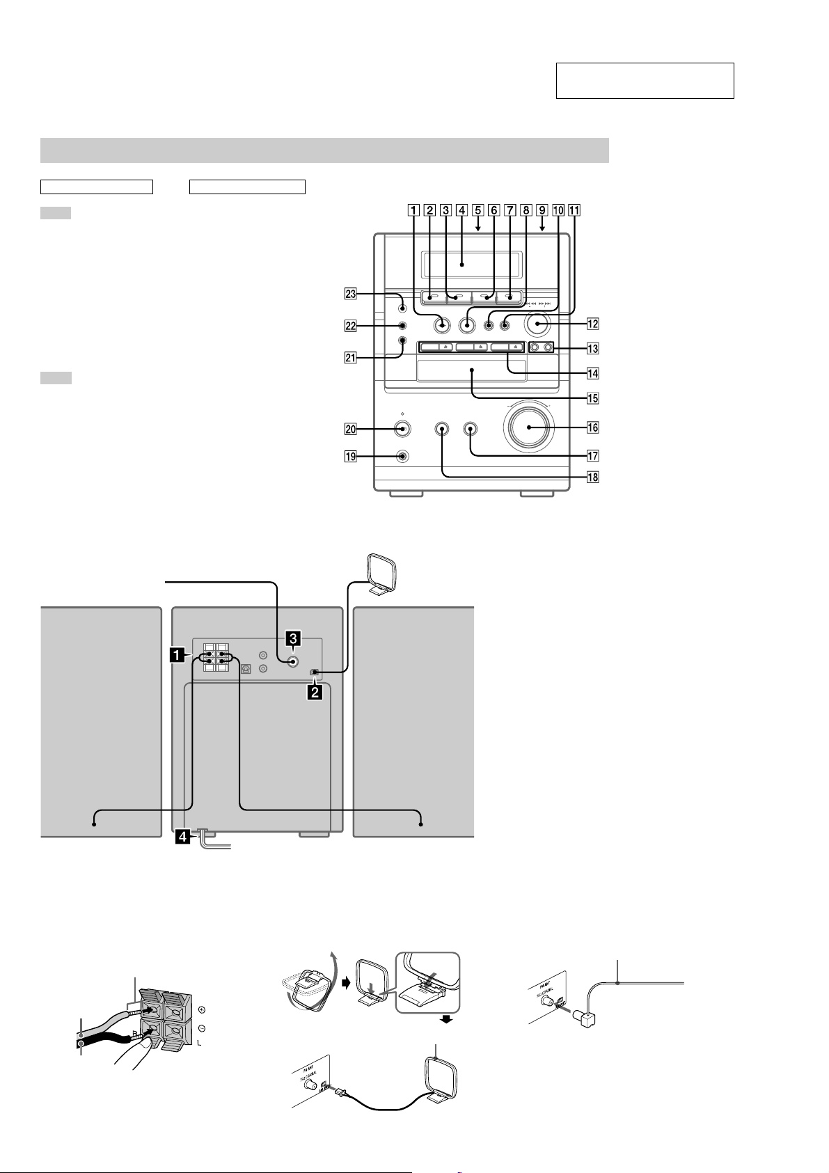
LOCATION OF CONTROLS
– Front Panel –
Main unit
SECTION 2
GENERAL
This section is extracted from
instruction manual.
ALPHABETICAL ORDER
A – M
Cassette compartment 5
CD 3
DISC 1/DISC 2/DISC 3 qf
Disc tray qg
DISC SKIP 3
DISPLAY ws
Display Window 4
ENTER 1
FM MODE/DIR wa
MD 7
MEGA BASS qk
MUSIC MENU qj
P – Z
PGM CLEAR 8
PHONES jack ql
PLAY MODE wa
PRESET +/– qd
Remote sensor wd
TAPE 2
TUNER 6
TUNER MEM q;
TUNING +/– qs
VOLUME control qh
– Back Panel –
FM antenna*
BUTTON DESCRIPTIONS
@/1 (power) w;
CD
. m (go back) qs
M > (go forward) qs
nN (play) 1
X (pause) q;
Z (eject) qf
x (stop) 8
TAPE
M > (fast forward) qs
X (pause) 0
nN (play) 1
z REC PAUSE/START qa
. m (rewind) qs
Z PUSH OPEN/CLOSE 9
x (stop) 8
AM loop
antenna
1 Connect the speakers.
Connect the speaker cords to the SPEAKER
terminals as shown below.
Insert only the
stripped portion.
Red (3)
Black (#)
4
Left speakerRight speaker
* Except for European model
2 Connect the AM antenna.
Set up the AM loop antenna, then connect
it.
AM loop antenna
3 Connect the FM antenna (except for
European model).
Extend the FM lead
antenna horizontally.
4 Connect the power cord to a wall outlet.
If the supplied adaptor on the plug does not
fit your wall outlet, detach it from the plug
(only for models equipped with the
adaptor).
To turn on the system, press [/ 1 (power).
HCD-EP707
A – M
CD qa
CLOCK/TIMER ON/OFF 2
CLOCK/TIMER SET 3
DISC SKIP 7
DISPLAY 6
ENTER qg
FM MODE 8
MD 9
MEGA BASS qf
MUSIC MENU +/– qj
MUTING qh
P – Z
PGM CLEAR qs
PLAY MODE w;
PRESET/CLOCK/TIMER +/–
wd
REPEAT/DIR wa
SLEEP 1
TAPE ql
TUNER/BAND q;
TUNER MEMORY qk
TUNING +/– ws
VOL (volume) +/– qd
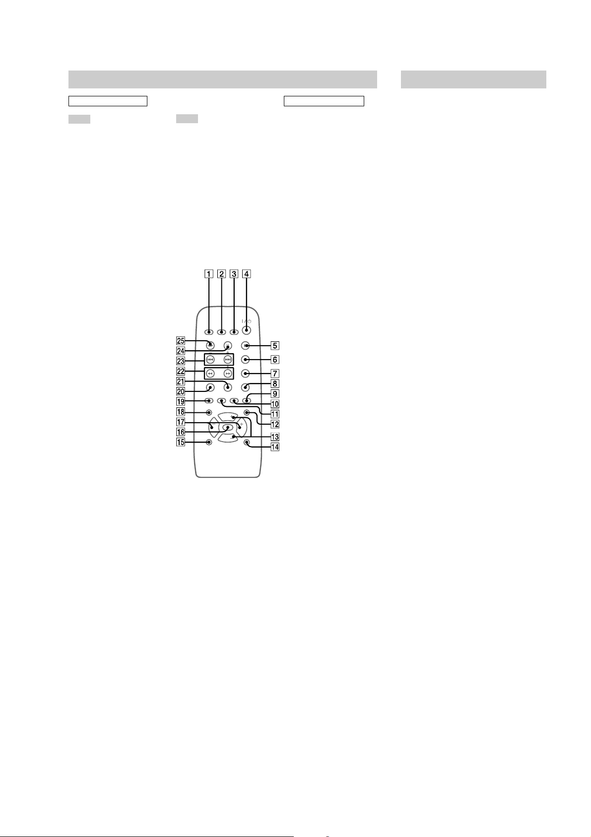
Remote control
@/1 (power) 4
m (rewind) M (fast forward)
ws
. (go back) > (go forward)
wd
X (pause) wf
nN (play) wg
x (stop) 5
Setting the clock
1
Turn on the system.
2
Press CLOCK/TIMER SET on the
remote.
3
Press CLOCK/TIMER SET on the
remote to select “SET CLK”, then press
ENTER.
4
Press . or > on the remote
repeatedly to set the hour.
5
Press ENTER.
6
Press . or > on the remote
repeatedly to set the minute.
7
Press ENTER.
The clock starts working.
If you make a mistake
Perform from step 1.
Note
The clock settings are canceled when you disconnect
the power cord or if a power failure occurs.
ALPHABETICAL ORDER
BUTTON DESCRIPTIONS
5

HCD-EP707
• This set can be disassembled in the order shown below.
3-1. DISASSEMBLY FLOW
SET
3-2. SIDE (PANEL)
(Page 7)
SECTION 3
DISASSEMBLY
3-3. TOP CABINET SECTION
(Page 7)
3-6. MAIN BOARD
(Page 9)
3-7. CD MECHANISM DECK
(CMCJ-0132)
(Page 9)
3-8. REGULATOR BOARD
(Page 10)
3-9. POWER AMP BOARD
(Page 10)
3-4. TAPE MECHANISM DECK
(CRL4349)
(Page 8)
3-10.COVER
(Page 11)
3-11.DRAWER
(Page 11)
3-12.OPTICAL BLOCK, BELT
(Page 12)
3-5. FRONT PANEL SECTION
(Page 8)
6
Note: Follow the disassembly procedure in the numerical order given.
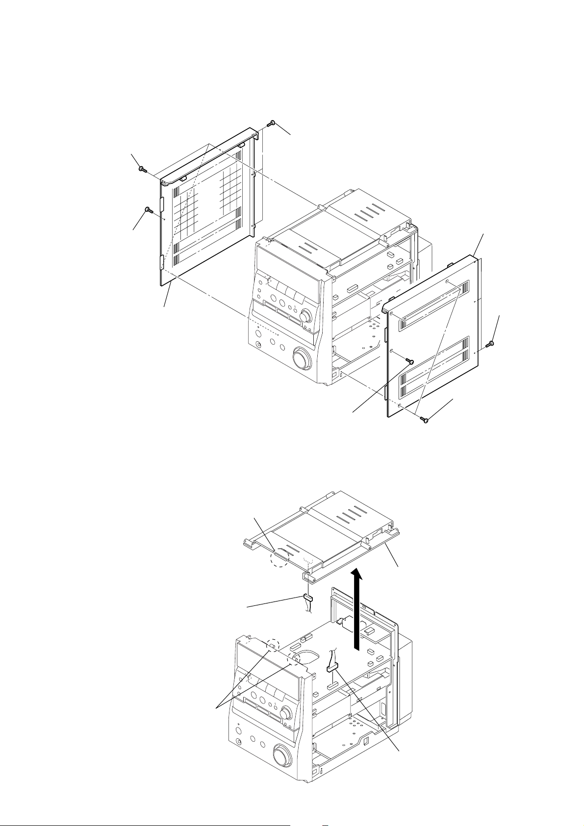
3-2. SIDE (PANEL)
2
three screws
×
8)
(KTP3
3
screw
(BVTP3
×
10)
4
side (panel) (L)
1
three screws
(KTP3
HCD-EP707
×
8)
8
side (panel) (R)
5
three screws
×
8)
(KTP3
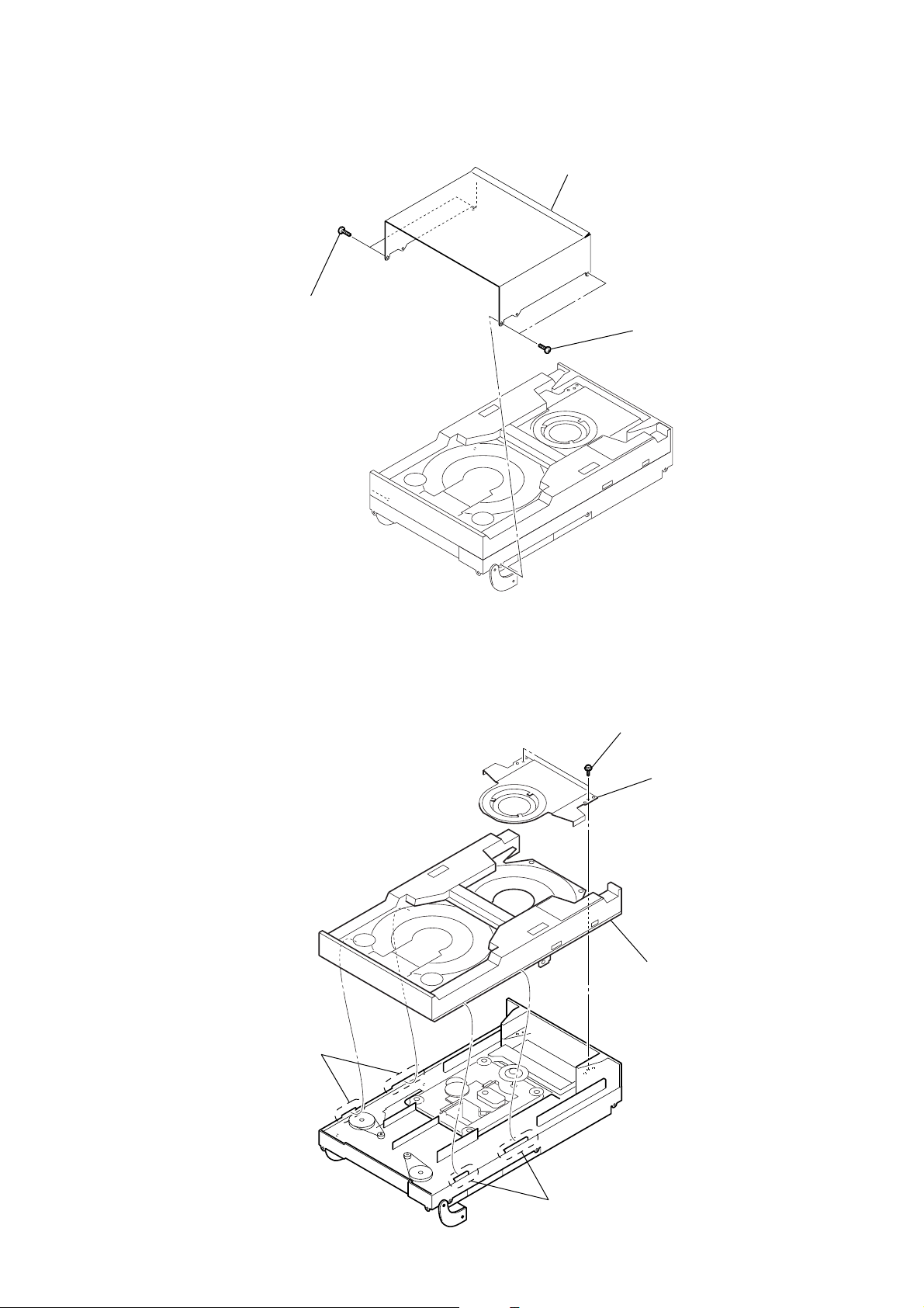
3-3. TOP CABINET SECTION
5
3
connector
claw
7
screw
(BVTP3
×
10)
4
6
top cabinet section
6
three screws
(KTP3
×
8)
2
two claws
1
connector
(CON209)
7
HCD-EP707
k
r
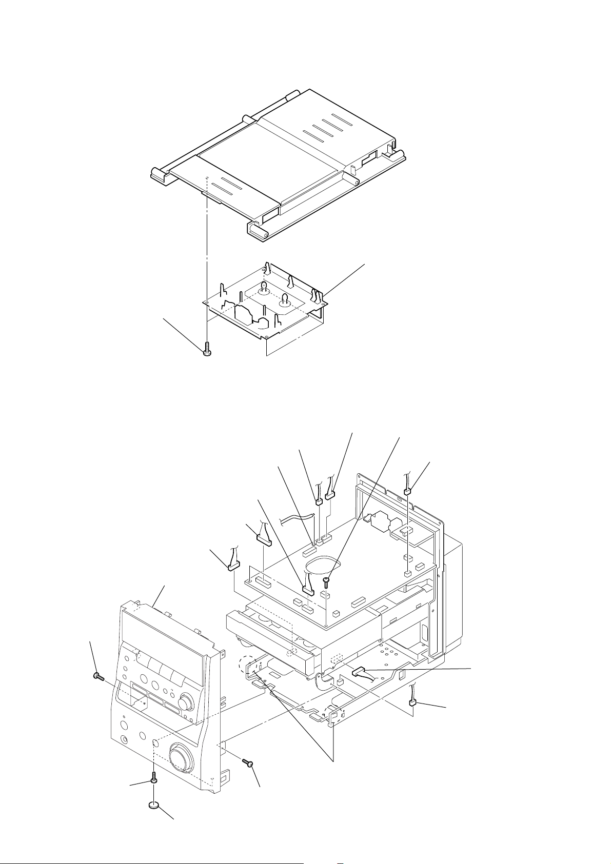
3-4. TAPE MECHANISM DECK (CRL4349)
4
four screws
(BVTP3 × 10)
2
tape mechanism dec
(CRL4349)
3-5. FRONT PANEL SECTION
3
connector
(CON806)
9
front panel section
6
screws
(BVTP3 × 10)
1
Remove a solder.
3
connector
(CON208)
3
connector
(CON207)
3
connector
(CON205)
3
connector
(CON203)
7
two screws
(BVTP3 × 12)
3
connector
(CON211)
2
connecto
2
connector
(CON810)
8
two claws
5
two screws
(KTP3 × 8)
4
two rubbers (foot)
6
screws
(BVTP3
×
10)
8
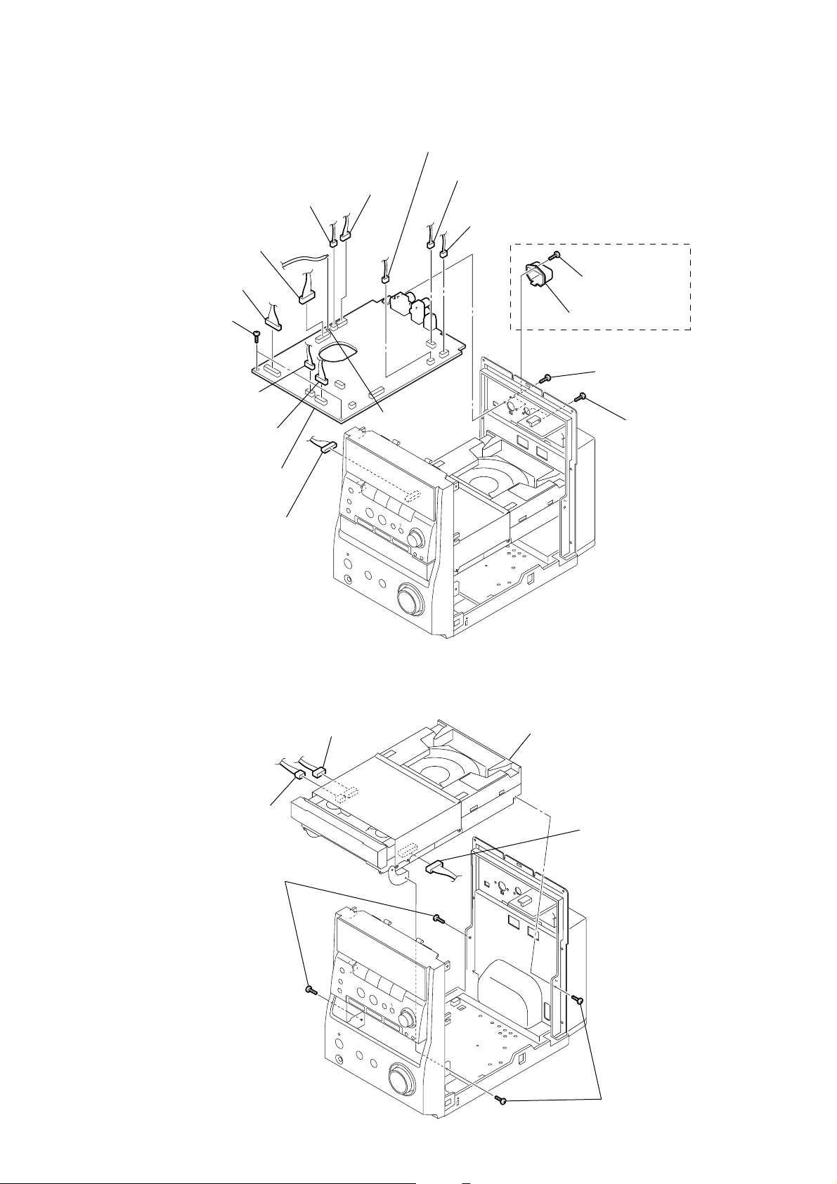
3-6. MAIN BOARD
)
)
2
2
connector
(CON207)
3
two screws
(BVTP3
×
12)
2
connector
(CON210)
2
2
connector
(CON216)
connector
(CON208)
connector
(CON205)
2
connector
(CON203)
2
connector
(CON211)
1
Remove a solder.
2
connector
(CON214)
2
connector
(CON215)
4
screw
(BTP2.6
5
antenna jack cover
6
two screws
(BVTT2
7
AEP, UK
×
8)
×
8)
two screws
(BVTP3
HCD-EP707
×
10
8
main board
2
connector
3-7. CD MECHANISM DECK (CMCJ-0132)
2
connector
2
connector
3
two screws
(BVTP3 × 10)
4
CD mechanism deck (CMCJ-0132)
1
connector
3
two screws
(BVTP3 × 10
9
HCD-EP707
)
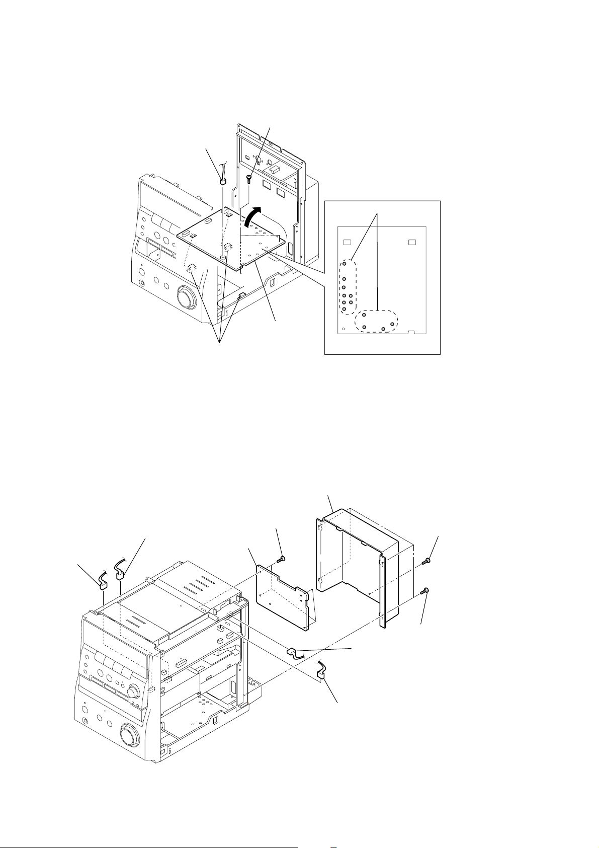
3-8. REGULATOR BOARD
1
connector
(CON810)
2
two screws
(BVTP3
×
8)
3-9. POWER AMP BOARD
3
three claws
4
6
regulator board
3
rear (cover)
Remove twelve solders.
5
regulator board
(bottom side view)
5
connector
(CON801)
5
connector
(CON808)
7
power amp board
6
four screws
(BVTP3
×
8)
4
connector
(CON214)
4
connector
(CON800)
1
four screws
(BVTP3
2
screw
(KTP3
×
10)
×
8
10
3-10. COVER
s
r
1
two screws
2
cover
1
two screw
HCD-EP707
3-11. DRAWER
3
two claws
1
two screws
2
arm
4
drawe
3
two claws
11
HCD-EP707
s
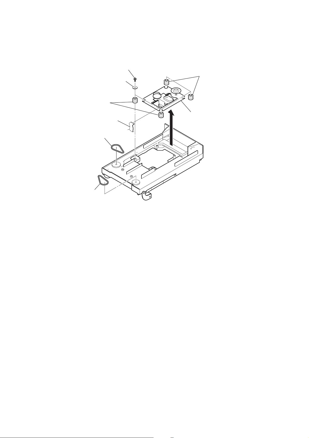
3-12. OPTICAL BLOCK, BELT
5
two cushions
1
four screws
four washers
2
5
two cushion
7
4
belt
flexible cable
7
belt
3
6
optical block
12
)
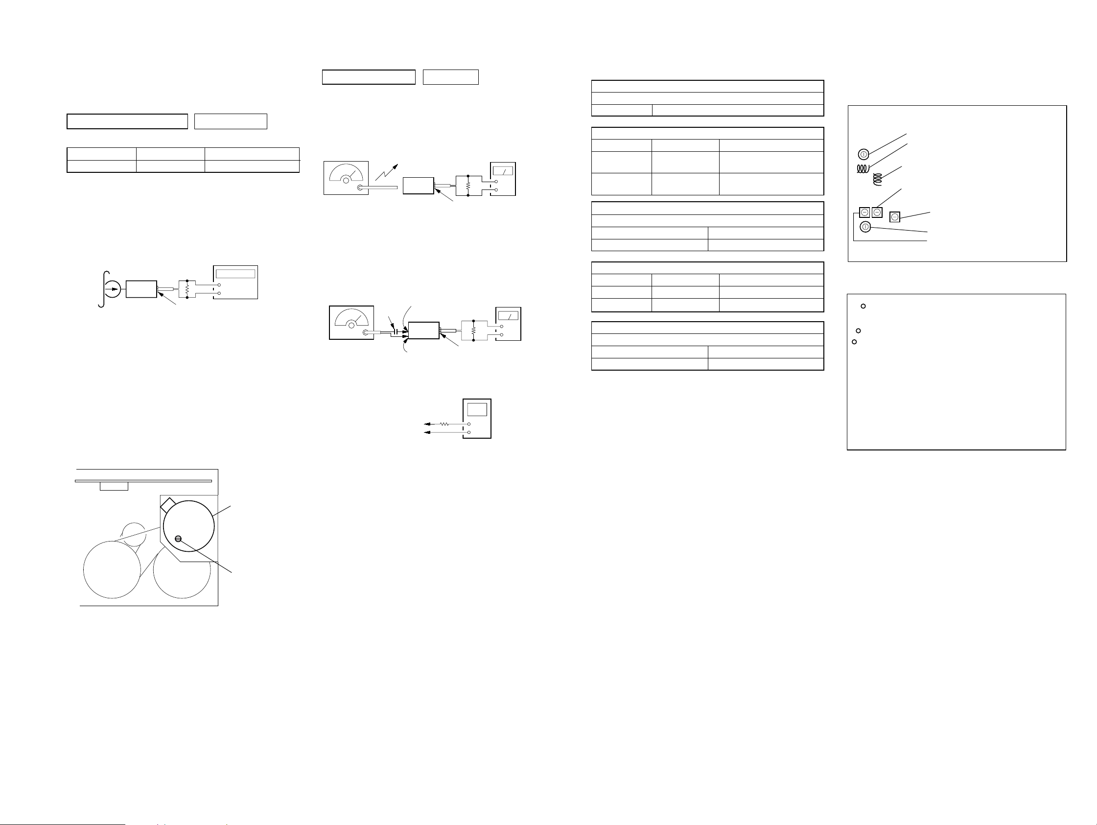
SECTION 4
ELECTRICAL ADJUSTMENTS
HCD-EP707
PRECAUTION
1. Setting
MEGA BASS switch : OFF
TAPE DECK SECTION 0 dB=0.775 V
Test tape
Type Signal Used for
WS-48B 3 kHz, 0 dB Tape Speed Adjustment
Tape Speed Adjustment
Setting:
Function: TAPE
test tape
WS-48B
(3 kHz, 0 dB)
set
Procedure:
1. Playback WS-48B (tape center) in the FWD state.
2. Adjsut the volume in CAPSTAN/REEL motor so that the frequency counter reading becomes 3,000 Hz.
Specified V alue: 2,910 to 3,090 Hz
3. Confirm that the frequency at the beginning and that at the
end of tape winding are between 2,955 to 3,045 Hz.
frequency counter
47 kΩ
+
–
SPEAKER JACK board
SPEAKER terminal (SP801)
TUNER SECTION 0 dB=1 µV
[AM]
Setting:
Function: TUNER
TUNER/BAND switch: AM
AM RF signal
generator
30% amplitude
modulation by
400 Hz signal
Output level: as low as possible
[FM]
Setting:
Function: TUNER
TUNER/BAND switch: FM
FM RF signal
generator
22.5 kHz frequency
deviation by 400 Hz
signal
Output level: as low as possible
Put the lead-wire
antenna close to
the set.
set
MAIN board
MAIN board
TP (GND)
TP (VT)
TP (GND)
TP (FM ANT)
set
0.01 µF
MAIN board
SPEAKER JACK board
SPEAKER terminal (SP801
digital voltmeter
100 kΩ
level meter
32 Ω
+
–
level meter
32 Ω
+
–
SPEAKER JACK board
SPEAKER terminal (SP801)
( ): AEP, UK models
AM IF ADJUSTMENT
Adjust for a maximum reading on level meter
IFT205 450 kHz
AM FREQUENCY COVERAGE ADJUSTMENT
Adjustment Part Frequency Display Reading on Digital Voltmeter
IFT201
Confirmation
Adjust for a maximum reading on level meter
IFT202 603 kHz
VC205 1,404 kHz
FM FREQUENCY COVERAGE CONFIRMATION
Adjustment Part Frequency Display Reading on Digital Voltmeter
L204 87.5 MHz 2.3 to 2.5 V (1.4 to 1.6 V)
Confirmation 108 MHz 6.3 to 7.3 V (7.3 to 8.5 V)
Adjust for a maximum reading on level meter
L203 90.1 MHz
VC202 106.1 MHz
530 kHz
(531 kHz)
1,710 kHz 7.8 ± 0.5 V
(1,602 kHz) (7.1 ± 0.5 V)
AM TRACKING ADJUSTMENT
FM TRACKING ADJUSTMENT
1.3 ± 0.1 V
Adjustment Location and Connecting Points
– MAIN BOARD (Component Side) –
L203
VC202
L204 FM Frequency Coverage Adjustment
IFT201 AM Frequency Coverage Adjustment
FM Tracking Adjustment
}
IFT205 AM IF Adjustment
IFT202
VC205
AM Tracking Adjustment
}
– MAIN BOARD (Conductor Side) –
TP
(VT)
TP
(GND)
TP
(FM ANT)
Adjustment Location:
CAPSTAN/REEL
motor
Tape Speed
Adjustment
Sample Value of Wow and Flutter: 0.3% or less W. RMS (JIS)
(WS-48B)
•Repeat the procedures in each adjustment several times, and the
frequency coverage and tracking adjustments should be finally
done by the trimmer capacitors.
1313
HCD-EP707
SECTION 5
DIAGRAMS
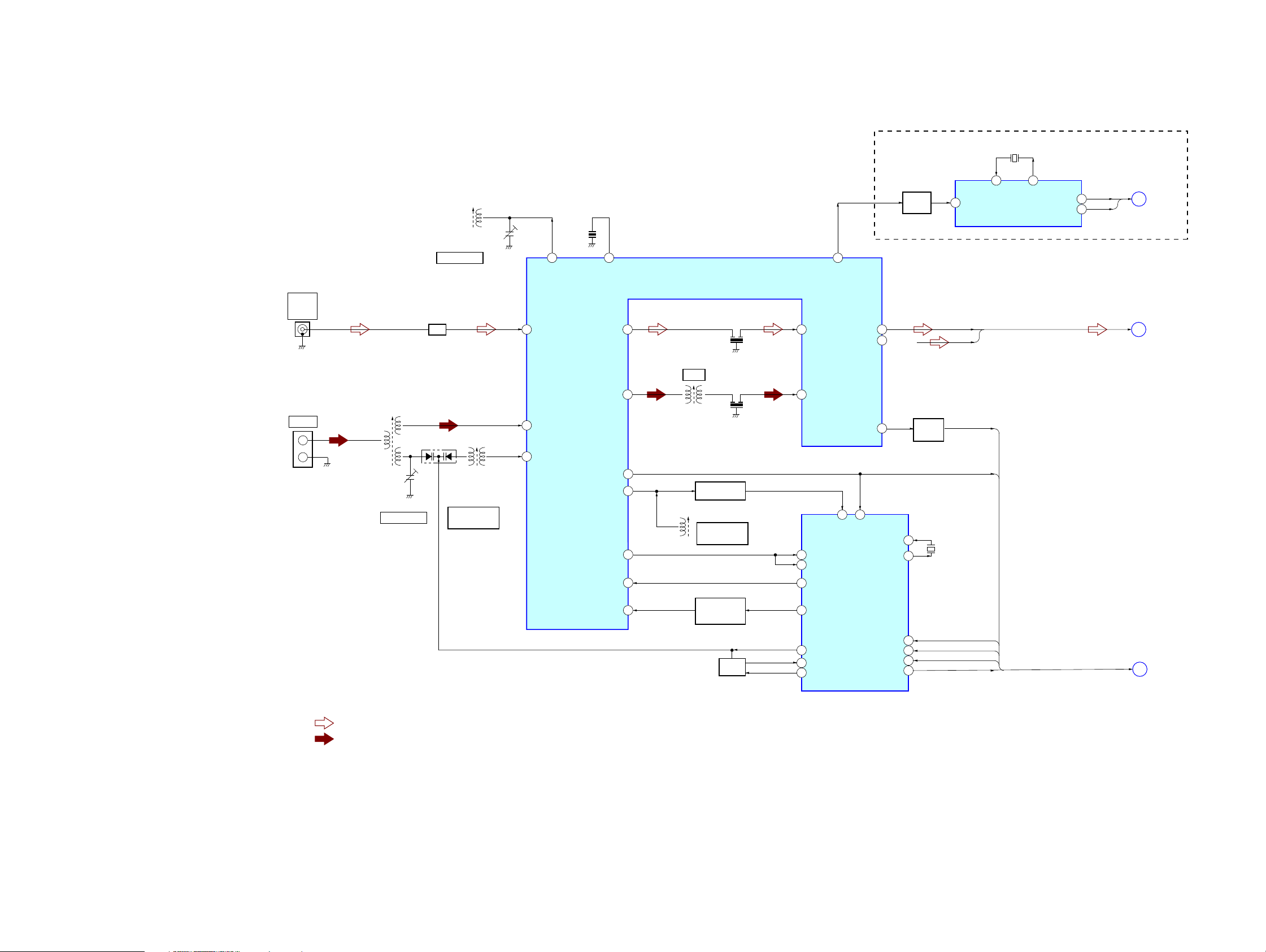
5-1. BLOCK DIAGRAM – TUNER Section –
CON201
FM ANT
75Ω
COAXIAL
CON202
AM ANT
• R-ch is omitted due
to same as L-ch.
• SIGNAL PATH
: FM
: AM
IFT202
AM RF
VC205
IFT202, VC205
AM TRACKING
L203, VC202
FM TRACKING
BPF201
BPF
Q201
L203
FM RF
IFT201
AM OSC
IFT201
AM FREQUENCY
COVERAGE
VC202
CF203
22
FMRF OUT
FMRF IN FMIF
24 5 10
AMRF IN
1
AM
3
OSC
13
FM DET
FM
MIX
AM
MIX
AMOSC
BUFFER
FMOSC
AM/FMIF
BUFFER
MONO/ST
AM/FM SW
FM/AM IF AMP,
MIX, DET, MPX, OSC
IC202
CF201
IFT205
AM IF
9 11
CF202
8
20
7
14
15
FM OSC BUFFER
Q252
L204
FM FREQUENCY
COVERAGE
FM/AM
SELECT SWITCH
Q204
L. P. F
(AEP, UK)
BUFFER
Q208
19
DET OUT
L OUT
16
R OUT
17
R-CH
AMIF
XIN
XOUT
BUFFER
Q202
CF204
7.2MHz
1
20
DI
4
CL
5
CE
3
DO
6
12
AGC
16
15
FMIN
AMIN
IFIN
12
IO1
11
BO2
8
FM/AM PLL
BO1
7
AOUT
20
AIN
19
PD
18
IC201
4
TU-L
TU-R
MUX
STATION
STEREO
DA IN
CLOCK
PLL CE
DA OUT
CF205
4.332MHz
13
XI
RDS DECODER
IC203
14
XO
RCLK
RDAT
RCLK
16
RDATA
2
H
A
B
(Page 17)
(Page 16)
(Page 16)
1414
 Loading...