

SONY HCD-EC55, HCD-EC77, HCD-GX99 Service Manual

HCD-EC55/EC77/GX99
SERVICE MANUAL
Ver. 1.1 2007.04
• HCD-EC55 (US model) and HCD-EC77/GX99 (US
and Canadian models) are the Amplifier, CD pla yer
and Tuner section in MHC-EC55/EC77/GX99.
• HCD-EC55 (Except US model) and HCD-EC77/
GX99 (Except US and Canadian models) are the
Amplifier, CD player, Tape Deck and Tuner section
in MHC-EC55/EC77/GX99.
Photo : HCD-EC55 (E model)
CD
Section
TAPE Model Name Using Similar Mechanism NEW
Section T ape Transport Mechanism T ype CS-21SC-901TP
US Model
HCD-EC55/EC77/GX99
Canadian Model
HCD-EC77/GX99
AEP Model
HCD-EC55/EC77
UK Model
HCD-EC55
E Model
Australian Model
HCD-EC55/EC77
Model Name Using Similar Mechanism NEW
Base Unit Name BU-K6BD90-WOD
Optical Pick-up Name KSM-213DCP
Main unit
AUDIO POWER SPECIFICATIONS
POWER OUTPUT AND TOTAL HARMONIC DISTORTION:
(HCD-GX99, HCD-EC77 The United States model only)
Low channel
With 8 ohm loads, both channels driven, from 120 – 10,000 Hz; 60 watts
per channel minimum RMS power, with no more than 0.7% total harmonic
distortion from 250 milliwatts to rated output.
High channel
With 8 ohm loads, both channels driven, from 2,000 – 13,000 Hz; 60 watts
per channel minimum RMS power, with no more than 0.7% total harmonic
distortion from 250 milliwatts to rated output.
AUDIO POWER SPECIFICATIONS
POWER OUTPUT AND TOTAL HARMONIC DISTORTION:
(HCD-EC55 The United States model only)
With 6 ohm loads, both channels driven, from 120 – 10,000 Hz; 45 watts
per channel minimum RMS power, with no more than 0.7% total harmonic
distortion from 250 milliwatts to rated output.
Amplifier section
HCD-GX99
Front speaker:
RMS output power (reference):
Low channel
95 W + 95 W (per channel at 8 Ω, 1 kHz, 10% THD)
High channel
95 W + 95 W (per channel at 8 Ω, 8 kHz, 10% THD)
Subwoofer:
RMS output power (reference):
150 W (at 6 Ω, 80 Hz, 10% THD)
HCD-EC77
North American model:
RMS output power (reference):
Low channel
95 W + 95 W (per channel at 8 Ω, 1 kHz, 10% THD)
High channel
95 W + 95 W (per channel at 8 Ω, 8 kHz, 10% THD)
SPECIFICATIONS
European and Russian models:
Power output (rated):
Low channel
45 W + 45 W (at 8 Ω, 1 kHz, 1% THD)
High channel
45 W + 45 W (at 8 Ω, 8 kHz, 1% THD)
RMS output power (reference):
Low channel
65 W + 65 W (per channel at 8 Ω, 1 kHz, 10% THD)
High channel
65 W + 65 W (per channel at 8 Ω, 8 kHz, 10% THD)
Other models:
The following are measured at AC 120, 127, 220, 240 V, 50/60 Hz
Power output (rated):
Low channel
50 W + 50 W (at 8 Ω, 1 kHz, 1% THD)
High channel
50 W + 50 W (at 8 Ω, 8 kHz, 1% THD)
RMS output power (reference):
Low channel
70 W + 70 W (per channel at 8 Ω, 1 kHz, 10% THD)
High channel
70 W + 70 W (per channel at 8 Ω, 8 kHz, 10% THD)
HCD-EC55
North American model:
RMS output power (reference):
65 W+ 65 W (per channel at 6 Ω, 1 kHz, 10% THD)
European and Russian models:
Power output (rated): 45 W + 45 W (at 6 Ω, 1 kHz, 1% THD)
RMS output power (reference):
65 W + 65 W (per channel at 6 Ω, 1 kHz, 10% THD)
Other models:
The following are measured at AC 120, 127, 220, 240 V, 50/60 Hz
Power output (rated): 45 W + 45 W (at 6 Ω, 1 kHz, 1% THD)
RMS output power (reference):
65 W + 65 W (per channel at 6 Ω, 1 kHz, 10% THD)
Inputs
AUDIO IN (stereo mini jack): Sensitivity 800 mV,
impedance 47 kilohms
Outputs
PHONES (stereo mini jack): Accepts headphones with
an impedance of 8 Ω or more
SPEAKER: Accepts impedance of 6 to 8 Ω
SUBWOOFER OUT (HCD-GX99 only)
CD player section
System: Compact disc and digital audio system
Laser: Semiconductor laser (λ=770 – 810 nm)
Emission duration: continuous
Frequency response: 20 Hz – 20 kHz
Signal-to-noise ratio: More than 90 dB
Dynamic range: More than 88 dB
Tape deck section (Except for NorthAmerican model)
Recording system: 4-track 2-channel, stereo
Tuner section
FM stereo, FM/AM superheterodyne tuner
Antenna:
FM lead antenna
AM loop antenna
FM tuner section:
Tuning range
North American model: 87.5 – 108.0 MHz (100 kHz step)
Other models: 87.5 – 108.0 MHz (50 kHz step)
Intermediate frequency: 10.7 MHz
— Continued on next page —
9-887-532-02
2007D16-1
© 2007.04
COMPACT DISC DECK RECEIVER
Sony Corporation
Home Audio Division
Published by Sony Techno Create Corporation
HCD-EC55/EC77/GX99
Ver. 1.1
AM tuner section:
Tuning range
Pan-American and Australian models:
530 – 1,710 kHz (with 10 kHz tuning interval)
531 – 1,710 kHz (with 9 kHz tuning interval)
European and Russian models:
531 – 1,602 kHz (with 9 kHz tuning interval)
Other models:
530 – 1,610 kHz (with 10 kHz tuning interval)
531 – 1,602 kHz (with 9 kHz tuning interval)
Intermediate frequency: 450 kHz
General
Powerrequirements:
North American model: AC 120 V, 60 Hz
European and Russian models: AC 230 V, 50/60 Hz
Australian model: AC 230 – 240 V, 50/60 Hz
Mexican model: AC 127 V, 60 Hz
Argentine model: A C 220 V, 50/60 Hz
Korean model: A C 220 V, 60 Hz
Other models: AC 120, 220 or 230 – 240 V, 50/60 Hz, adjustable with voltage
selector
Power consumption:
HCD-GX99
USA model: 190 W
Canadian model: 245 VA
HCD-EC77
USA model: 190 W
Canadian model: 245 VA
European and Russian models: 140 W
Other models: 150 W
HCD-EC55
USA model: 95 W
European and Russian models: 95 W
Other models: 95 W
Dimensions (w/h/d)(excl. speakers):
Approx. 200 × 306 × 410 mm
Mass (excl. speakers):
HCD-GX99
North American model: Approx. 6.1 kg
HCD-EC77
North American and European models: Approx. 6.1 kg
Other models: Approx. 6.4 kg
HCD-EC55
North American model: Approx. 5.0 kg
Other models: Approx. 5.3 kg
Design and specifications are subject to change without notice.
0.5 W (in Power Saving Mode)
0.5 W (in Power Saving Mode)
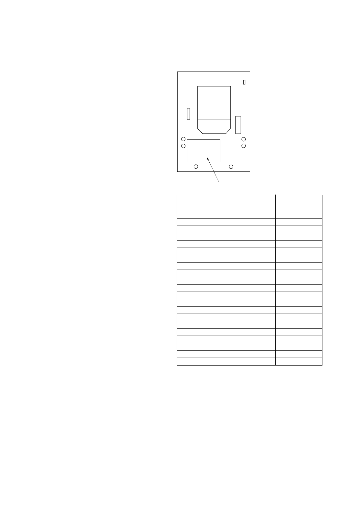
MODEL IDENTIFICATION
– Back Panel –
Parts No.
Model Part No.
GX99: CND model 2-319-061-0[]
EC55: AEP, UK model 2-893-579-0[]
EC55: RU model 2-893-580-0[]
EC55: E2 model 2-893-581-0[]
EC55: E51 model 2-893-582-0[]
EC55: MX model 2-893-583-0[]
EC55: AR model 2-893-584-0[]
EC55: SP model 2-893-586-0[]
EC55: AUS model 2-893-587-0[]
EC55: KR model 2-893-588-0[]
EC77: CND model 2-893-595-0[]
EC77: RU model 2-893-597-0[]
EC77: E2 model 2-893-598-0[]
EC77: E51 model 2-893-599-0[]
EC77: MX model 2-893-600-0[]
EC77: AR model 2-893-601-0[]
EC77: AUS model 2-893-604-0[]
EC55: US model 3-095-136-0[]
EC77: AEP model 3-095-137-0[]
EC77: E3 model 3-095-138-0[]
GX99: US model 3-095-139-0[]
EC77: US model 3-095-495-0[]
SAFETY-RELATED COMPONENT WARNING!!
COMPONENTS IDENTIFIED BY MARK 0 OR DOTTED LINE
WITH MARK 0 ON THE SCHEMATIC DIAGRAMS AND IN
THE PARTS LIST ARE CRITICAL TO SAFE OPERATION.
REPLACE THESE COMPONENTS WITH SONY PARTS WHOSE
PART NUMBERS APPEAR AS SHOWN IN THIS MANUAL OR
IN SUPPLEMENTS PUBLISHED BY SONY.
ATTENTION AU COMPOSANT AYANT RAPPORT
À LA SÉCURITÉ!
LES COMPOSANTS IDENTIFIÉS PAR UNE MARQUE 0 SUR
LES DIAGRAMMES SCHÉMATIQUES ET LA LISTE DES
PIÈCES SONT CRITIQUES POUR LA SÉCURITÉ DE
FONCTIONNEMENT. NE REMPLACER CES COM- POSANTS
QUE PAR DES PIÈCES SONY DONT LES NUMÉROS SONT
DONNÉS DANS CE MANUEL OU D ANS LES SUPPLÉMENTS
PUBLIÉS PAR SONY.
2
•Abbreviation
AR : Argentine model
AUS:Australian model
CND : Canadian model
E2 : 120 V AC area in E model
E3 : 240 V AC area in E model
E51 : Chilean and Peruvian models
KR : Korean model
MX : Mexican model
RU : Russian model
SP : Singapore model

TABLE OF CONTENTS
HCD-EC55/EC77/GX99
1. SERVICING NOTES ................................................ 4
2. GENERAL ................................................................... 6
3. DISASSEMBLY
3-1. Disassembly Flow ........................................................... 8
3-2. Side Panel (R), Side Panel (L)......................................... 9
3-3. Top Panel Assy (Except US, CND) ................................. 10
3-4. Top Panel (US, CND)...................................................... 10
3-5. Front Panel Assy.............................................................. 11
3-6. Mechanical Deck (Except US, CND).............................. 12
3-7. Belt (MAIN), Belt (R/F) (Except US, CND) .................. 12
3-8. KEY-LEFT Board............................................................ 13
3-9. KEY-RIGHT Board, KEY-CD Board, PANEL Board .... 13
3-10. JACK Board..................................................................... 14
3-11. MAIN Board.................................................................... 15
3-12. CD Mechanical................................................................ 16
3-13. Optical Pick-up (KSM-213DCP), BD90 Board .............. 17
3-14. Belt (DLM3A) ................................................................. 18
3-15. Chassis............................................................................. 18
3-16. PT Board (Except EC55:US), PT (U) Board (EC55:US),
Power Transformer .......................................................... 19
3-17. LOW-AMP Board, HI-AMP Board (EC77/GX99) ......... 19
3-18. HI-AMP Board (EC55) ................................................... 20
3-19. DC Fan ............................................................................ 20
4. TEST MODE ............................................................... 21
5. MECHANICAL ADJUSTMENTS......................... 25
6. ELECTRICAL ADJUSTMENTS .......................... 25
7. DIAGRAMS
7-1. Block Diagram — BD/DRIVER Section — .................. 30
7-2. Block Diagram — TUNER Section — .......................... 31
7-3. Block Diagram — MAIN Section — ............................. 32
7-4. Printed Wiring Board — BD90 Board — ...................... 33
7-5. Schematic Diagram — BD90 Board — ......................... 34
7-6. Printed Wiring Boards — MAIN Section — ................. 35
7-7. Schematic Diagram — MAIN Section (1/2) — ............. 36
7-8. Schematic Diagram — MAIN Section (2/2) — ............. 37
7-9. Printed Wiring Board — PANEL Board — ................... 38
7-10. Schematic Diagram — PANEL Board — ...................... 39
7-11. Printed Wiring Boards — KEY Section — .................... 40
7-12. Schematic Diagram — KEY Section — ........................ 40
7-13. Printed Wiring Board — HI-AMP Board —.................. 41
7-14. Schematic Diagram — HI-AMP Board — .................... 42
7-15. Printed Wiring Board
— LOW-AMP Board (EC77/GX99) — .......................... 43
7-16. Schematic Diagram
— LOW-AMP Board (EC77/GX99) — .......................... 44
7-17. Printed Wiring Boards
— DECK Section (Except US,CND) —......................... 45
7-18. Schematic Diagram
— DECK Section (Except US,CND) —......................... 45
7-19. Printed Wiring Board
— PT Board (Except EC55: US) — ............................... 46
7-20. Schematic Diagram
— PT Board (Except EC55: US) — ............................... 46
7-21. Printed Wiring Board — PT (U) Board (EC55: US) —. 47
7-22. Schematic Diagram — PT (U) Board (EC55: US) — ... 47
8. EXPLODED VIEWS
8-1. Overall Section ................................................................ 57
8-2. Front Panel Section ......................................................... 58
8-3. Chassis Section (EC77/GX99) ........................................ 59
8-4. Chassis Section (EC55) ................................................... 60
8-5. Top Section (Except US, CND)....................................... 61
8-6. CD Mechanism Deck Section ......................................... 62
9. ELECTRICAL PARTS LIST .................................. 63
3

HCD-EC55/EC77/GX99
r
SECTION 1
SERVICING NOTES
CAUTION
Use of controls or adjustments or performance of procedures
other than those specified herein may result in hazardous radiation
exposure.
Notes on chip component replacement
• Never reuse a disconnected chip component.
• Notice that the minus side of a tantalum capacitor may be
damaged by heat.
Flexible Circuit Board Repairing
• Keep the temperature of the soldering iron around 270 °C
during repairing.
• Do not touch the soldering iron on the same conductor of the
circuit board (within 3 times).
• Be careful not to apply force on the conductor when soldering
or unsoldering.
SAFETY CHECK-OUT
After correcting the original service problem, perform the following
safety check before releasing the set to the customer:
Check the antenna terminals, metal trim, “metallized” knobs, screws,
and all other exposed metal parts for AC leakage.
Check leakage as described below.
LEAKAGE TEST
The AC leakage from any exposed metal part to earth ground and
from all exposed metal parts to any exposed metal part having a
return to chassis, must not exceed 0.5 mA (500 microamperes.).
Leakage current can be measured by any one of three methods.
1. A commercial leakage tester, such as the Simpson 229 or RCA
WT -540A. Follow the manuf acturers’ instructions to use these
instruments.
2. A battery-operated AC milliammeter . The Data Precision 245
digital multimeter is suitable for this job.
3. Measuring the voltage drop across a resistor by means of a
VOM or battery-operated AC v oltmeter. The “limit” indication
is 0.75 V, so analog meters must hav e an accurate low-v oltage
scale. The Simpson 250 and Sanwa SH-63Trd are examples
of a passive VOM that is suitable. Nearly all battery operated
digital multimeters that have a 2 V A C range are suitable. (See
Fig. A)
To Exposed Metal
Parts on Set
AC
0.15 µF
1.5 k
Ω
Earth Ground
voltmete
(0.75 V)
Fig. A. Using an AC voltmeter to check AC leakage.
This appliance is classified as a CLASS 1 LASER product.
The CLASS 1 LASER PRODUCT MARKING is located on
the rear exterior.
Laser component in this product is capable of emitting radiation
exceeding the limit for Class 1.
NOTES ON HANDLING THE OPTICAL PICK-UP
BLOCK OR BASE UNIT
The laser diode in the optical pick-up block may suffer electrostatic
break-down because of the potential difference generated by the
charged electrostatic load, etc. on clothing and the human body.
During repair, pay attention to electrostatic break-down and also
use the procedure in the printed matter which is included in the
repair parts.
The flexible board is easily damaged and should be handled with
care.
NOTES ON LASER DIODE EMISSION CHECK
The laser beam on this model is concentrated so as to be focused on
the disc reflective surface by the objective lens in the optical pickup block. Therefore, when checking the laser diode emission,
observe from more than 30 cm away from the objective lens.
LASER DIODE AND FOCUS SEARCH OPERATION
CHECK
Carry out the “S curve check” in “CD section adjustment” and check
that the S curve waveforms is output three times.
UNLEADED SOLDER
Boards requiring use of unleaded solder are printed with the leadfree mark (LF) indicating the solder contains no lead.
(Caution: Some printed circuit boards may not come printed with
the lead free mark due to their particular size)
: LEAD FREE MARK
Unleaded solder has the following characteristics.
• Unleaded solder melts at a temperature about 40 °C higher
than ordinary solder.
Ordinary soldering irons can be used but the iron tip has to be
applied to the solder joint for a slightly longer time.
Soldering irons using a temperature regulator should be set to
about 350 °C.
Caution: The printed pattern (copper foil) may peel away if
the heated tip is applied for too long, so be careful!
• Strong viscosity
Unleaded solder is more viscou-s (sticky, less prone to flow)
than ordinary solder so use caution not to let solder bridges
occur such as on IC pins, etc.
• Usable with ordinary solder
It is best to use only unleaded solder but unleaded solder may
also be added to ordinary solder.
CAUTION
When carrying this system
1
Remove all discs to protect the CD mechanism.
2
Hold down CD u (play/pause) on the unit, and press
?/1 until “STANDBY” appears.
3
After “LOCK” appears, unplug the power cord.
4
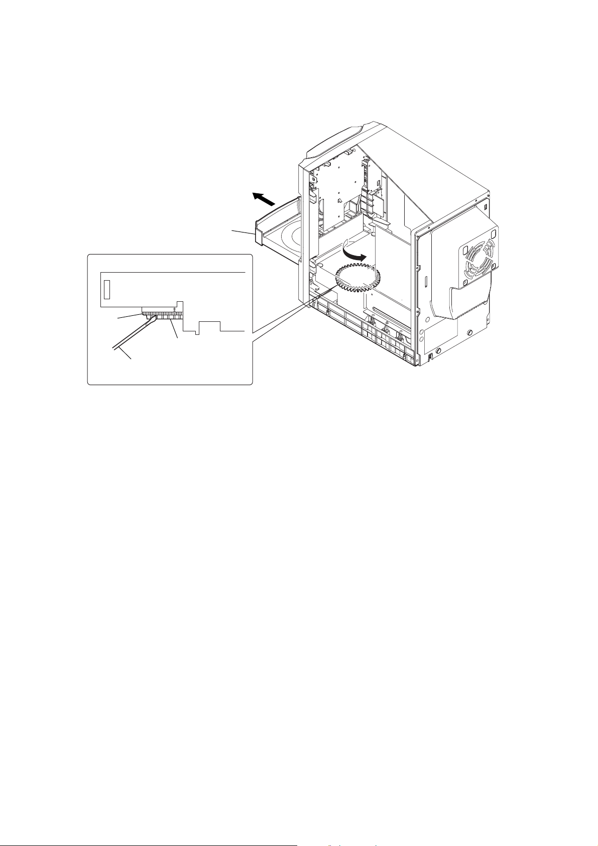
HOW TO OPEN THE DISC TRAY WHEN POWER SWITCH TURNS OFF
Turn the bottom rib (not the gear) with a flathead screwdriver in the direction of arrow A, and
draw out the tray in the direction of arrow B.
B
tray
A
HCD-EC55/EC77/GX99
gear
bottom rib
flathead screwdriver
5

HCD-EC55/EC77/GX99
Basic Operations
*
*Except for North American model
SECTION 2
GENERAL
Adjusting the sound
To adjust the volume
Press VOLUME +/– on the remote (or turn the
VOLUME control on the unit)
To add a sound eect
To Pr ess
Generate a more dynamic
sound (Dynamic Sound
Generator X-tra)
Set the sound eect
To turn on the subwoofer
Press SUBWOOFER ON/OFF in the lower part of the
subwoofer until the indicator on the subwoofer lights up.
*To adjust the sound output level for the subwoofer, turn the
SUBWOOFER LEVEL in the lower part of the subwoofer. Once you
have made the adjustment, the overall sound level can be adjusted
using VOLUME +/– on the remote (or turn the VOLUME control
ȶ
on the unit)
.
Playing a CD/MP3 disc
1
Select the CD function.
Press CD on the remote (or FUNCTION repeatedly)
Ȭ
.
2
Place a disc.
Press ì (open/close)
disc with the label side up on the disc tray. To place
additional discs, slide the disc tray with your nger as
shown below.
To c lo se the disc tray, press ì (open/close)
unit.
Do not force the disc tray closed with your nger, as
this may damage the unit.
ȶ
.
Ȱ
DSGX
Ȱ
EQ
.
(HCD-GX99 only)
ȱ
on the unit, and place a
on the unit.
ȱ
on the
This section is extracted
from instruction manual.
Notes on playing multisession discs
ˎIf the disc begins with a CD-DA (or MP3) session, it is recognized
as a CD-DA (or MP3) disc, and playback continues until another
session is encountered.
ˎA disc with a mixed CD format is recognized as a CD-DA (audio)
disc.
Listening to the radio
1
Select “FM” or “AM.”
Press TUNER/BAND
2
Select the tuning mode.
Press TUNING MODE
appears.
3
Tune in the desired station.
Press +/– on the remote (or TUNING + or – on the
ȭ
unit)
Scanning stops automatically when a station is tuned
in, and then “TUNED” and “STEREO” (for stereo
programs) appear.
To stop automatic scanning
Press Ą (stop) ȭ.
To tune in a station with a weak signal
If “TUNED” does not appear and the scanning does
not stop, press TUNING MODE
“MANUAL” appears and press +/– on the remote (or
TUNING + or – on the unit)
desired station.
To reduce static noise on a weak FM stereo
station
Press FM MODE Ȯ on the remote repeatedly until
“MONO” appears to turn o stereo reception.
Ȭ
repeatedly.
Ȯ
repeatedly until “AUTO”
.
Ȯ
repeatedly until
ȭ
repeatedly to tune in the
Before using the system
To use the remote
Slide and remove the battery compartment lid Ȼ, and
insert the two R6 (size AA) batteries (supplied), × side
rst, matching the polarities shown below.
Notes on using the remote
ˎWith normal use, the batteries should last for about six months.
ˎDo not mix an old battery with a new one or mix dierent types of
batteries.
ˎIf you do not use the remote for a long period of time, remove the
batteries to avoid damage from batter y leakage and corrosion.
ˎBatteries installed devices shall not be exposed to excessive heat such
as sunshine, re or the like.
To set the clock
1
Turn on the system.
Press ÒÄÆ (on/standby)
2
Select the clock set mode.
Press CLOCK/TIMER SET
current mode appears on the display, press Ã/Ñ
ȭ
on the remote repeatedly to select “CLOCK,” and
then press ENTER
3
Set the time.
Press Ã/Ñ
the hour, and then press ENTER
Use t he same procedure to set the minutes.
e clock settings are lost when you disconnect the
power cord or if a power failure occurs.
ȩ
.
ȹ
on the remote. If the
Ⱥ
on the remote.
ȭ
on the remote repeatedly to set
Ⱥ
on the remote.
Selecting a music source
Ȭ
on the remote.
Ȭ
3)
on
until
Ȭ
Ȭ
.
Press the following buttons (or press FUNCTION
repeatedly).
To select Press
CD
Tun e r
1)
Tap e
2)
(connected
Component
using an audio cord)
1)
Except for North American model.
2)
If the component has the AVLS (Automatic Volume Limiter System)
or BASS BOOST function, turn o the function to avoid distorted
sound from the speakers.
3)
North American model only.
CD
TUNER/BAND
TAP E Ȭ on the remote.
FUNCTION repeatedly
(or AUDIO IN
the remote)
“AU D I O IN” appears.
3
Select a disc.
If the discs are currently stopped, press DISC SKIP on
the remote (or DISC SKIP/EX-CHANGE on the unit)
ȳ
. To change discs while in other func tions, press
Ȳ
on the unit.
DISC 1 – 3
4
Start playback.
Press à (play) (or CD ā (play/pause) on the unit)
Ȭ
.
To e xc hange othe r discs during playback, press DISC
SKIP/EX-CHANGE
To Pr ess
Pause playb ack
Stop playback
Select a folder on an
MP3 disc
Select a track or le
Find a point in a
track or le
Select Repeat Play
To change the play mode
Press PLAY MODE Ȯ repeatedly while the player is
stopped. You can select normal play (no display for all
discs or “1 DISC” for a disc or “
in the folder on the disc), shue play (“SHUF” for
all discs shue, “1 DISC SHUF” for one disc shue
SHUF*” for folder shue), or program play
or “
(“PGM”).
*When playing a CD-DA disc, (SHUF) Play performs the same
operation as 1 DISC (SHUF) Play.
Notes on Repeat Play
ˎAll tracks or les on a disc are played repeatedly up to ve times.
ˎYo u cannot select “REP” and “SHUF” (all discs shue) at the same
time.
ˎ“REP1” indicates that a single track or le is repeated until you stop
it.
Notes on playing MP3 discs
ˎDo not save other types of tracks or les or unnecessary folders on a
disc that has MP3 les.
ˎFolders that have no MP3 les are skipped.
ˎMP3 les are played back in the order that they are recorded onto
the disc.
ˎe system can only play MP3 les that have a le extension of
“.MP3”.
ˎIf there are les on the disc that have the “.MP3” le extension,
but that are not MP3 les, the unit may produce noise or may
malfunction.
ˎe maximum number of:
ˋloadable sessions on a single disc is 10.
ˋfolders is 150 (including the root folder).
ˋMP3 les is 255.
ˋMP3 les and folders that can be contained on a single disc is 300.
ˋfolder levels (the tree structure of les) is eight.
ˎCompatibility with all MP3 encoding/writing soware, recording
device, and recording media cannot be guaranteed. Incompatible
MP3 discs may produce noise or interrupted audio or may not play
at all.
ȳ
on the unit.
ê (pause) on the remote (or CD
ā on the unit)
play, press the button again.
Ą (stop)
Ȭ
. To resume
ȭ
.
+/– ȯ.
ÃÄÑ (go back/go forward)
on the remote (øÄÞ on the
ȭ
.
unit)
Hold down ù/ß (rewind/fast
ȭ
during playback, and
forward)
release the button at the desired
point.
Ȯ
on the remote
REPEAT
repeatedly until “REP” or “REP1”
appears.
” for all MP3 les
Playing a tape (Except for North
American model)
1
Select a tape function.
Press TAPE on the remote (or FUNCTION on the
unit repeatedly)
2
Insert a tape.
Press Ąì (stop/eject)
tape into the cassette holder. Make sure there is no
slack in the tape to avoid damaging the tape or the
tape deck.
3
Start playback.
Press à (play)
To Pr ess
Pause playb ack
Stop playback
Rewind or fast
forward*
*Be sure to press Ąì (stop/eject) ȫ on the unit aer the tape has
been wound or rewound to the end.
Note
Do not turn o the system during playback or recording.
Ȭ
.
ȫ
on the unit, and insert the
ȫ
on the unit.
ȫ
ê (pause)
on the unit. To resume
play, press the button again.
Ąì (stop/eject)
ù/ß
ȫ
on the unit.
ȫ
on the unit.
Changing the display
To Pr ess
Change
information on the
display*
Change Display
mode (See below.)
*For example, you can view CD/MP3 disc information, such as the
track or le number or folder name during normal play, or the total
playing time while the player is stopped.
e system oers the following display modes.
Display mode When the system is o1),
Power Saving
2)
Mode
3)
Clock
1)
e STANDBY indicator on the unit lights up when the system is
o.
2)
You ca nnot set the clock in Power Saving Mode.
3)
e clock display automatically turns to Power Saving Mode aer
eight seconds.
Notes on the display information
ˎCharacters that cannot be displayed appear as “_”.
ˎe following are not displayed;
ˋtotal playing time for an MP3 disc.
ˋremaining playing time for an MP3 le.
ˎe following are not displayed correctly;
ˋelapsed playing time of an MP3 le encoded using a VBR (variable
bit rate).
ˋfolder and le names that do not follow either the ISO9660 Level
1, Level 2 or Joliet in the expansion format.
ˎe following are displayed;
ˋtotal playing time for a CD-DA disc when the play mode is “1
DISC”.
ˋremaining playing time for a track.
ˋID3 tag information for MP3 les when ID3 version 1 and version
2 tags are used (ID3 version 2 tag information display has priority
when both ID3 version 1 and version 2 tags are used for a single
MP3 le).
ˋup to 15 characters of ID3 tag information using uppercase letters
(A to Z), numbers (0 to 9), and symbols (‘< > * + , – / @ [ \ ] _).
repeatedly when the
DISPLAY
system is turned on.
repeatedly when the
DISPLAY
system is turned o.
e display is turned o to conserve
power. e timer and clock continue
to operate.
e clock is displayed.
6

Using optional audio components
Recording onto a tape (Except for
North American model)
Use a TYPE I (normal) tape only.
You c an record just the portions you like from a sound
source, including connected audio components.
Use b utton s on the unit to control tape recording.
1
Insert a recordable tape into the cassette holder
with the side you want to record facing up.
2
Prepare the recording source.
Select the desired source to record.
Place the disc you want to record and press DISC
SKIP/EX-CHANGE
ȳ
to select a disc.
When recording a folder from an MP3 disc, press
PLAY MODE
Ȯ
repeatedly to select “ ,” a nd then
press
+/– ȯ repeatedly to select the desired
folder.
To record only your favorite CD tracks or MP3 les in
your desired order, perform steps 2 to 5 of “Creating
your own CD program.”
3
Start recording.
Press Ć (record)
ȫ
, and then start playing the
desired recording source.
e CD starts playing automatically aer 10 seconds
have passed.
If there is noise while recording from the tuner,
reposition the appropriate antenna to reduce the
noise.
While recording, you cannot listen to other sources.
To s top recording
Press Ąìȫ.
Tip
We r ecommend that you press êȫ rst, and then press Ąìȫ to
avoid noise being recorded when you stop recording.
Using the timers
e system oers two timer functions. If you use both
timers, the Sleep Timer has priority.
Sleep Timer:
You c an fall asleep to music. is function works even if
the clock is not set.
Press SLEEP
Ƚ
on the remote repeatedly. If you select
“AU T O ,” the system automatically turns o aer the
current disc or tape stops or in 100 minutes.
If the tape deck is still playing or recording at the set
time, the system turns o aer the tape deck stops.
Play Timer:
You c an wake up to CD or tuner at a preset time.
Use b utton s on the remote to control the Play Timer.
Make sure you have s et the clock.
1
Prepare the sound source.
Prepare the sound source, and then press VOLUME
+/–
ȶ
to adjust the volume.
To start from a specic CD track or MP3 le, create
your own CD program.
2
Press CLOCK/TIMER SET ȹ.
3
Press Ã/Ñȭ repeatedly to select “PLAY,” and
then press ENTER
Ⱥ
.
“ON TIME” appears, and the hour indication ashes.
4
Set the time to start playing.
Press Ã/Ñ
ȭ
repeatedly to set the hour, and
then press ENTER
Ⱥ
.
e minute indication ashes. Use the procedure
above to set the minutes.
5
Use the same procedure as in step 4 to set the time
to stop playing.
6
Select the sound source.
Press Ã/Ñ
ȭ
repeatedly until the desired
sound source appears, and then press ENTER
Ⱥ
. e
display shows the timer settings.
7
Press ÒÄÆȩ to turn o the system.
If the system is on at the preset time, the Play Timer
will not play.
To activate or check the timer again
Press CLOCK/TIMER SELECT ȹ, press Ã/Ñ
ȭ
repeatedly until “PLAY SEL” appears, and then press
ENTER
Ⱥ
.
To cancel the timer
Repeat the same procedure as above until “OFF” appears,
and then press ENTER
Ⱥ
.
To change the setting
Start over from step 1.
Tip
e Play Timer setting remains as long as the setting is not canceled
manually.
To connect an optional headphones
Connect headphones to the PHONES jack ȴ on the
unit.
To connect an optional component
Connect additional audio source components to the
AUDI O IN jack
cord (not supplied). Turn down the volume on the
system, and then select the AUDIO IN function.
ȵ
on the unit using an analog audio
Other Operations
HCD-EC55/EC77/GX99
Creating your own CD program
(Program Play)
Use b utton s on the remote to create your own program.
1
Press CD Ȭ to select the CD function.
2
Press PLAY MODE Ȯ repeatedly until “PGM” appears
while the player is stopped.
3
Press DISC SKIP ȳ to select a disc.
4
Press Ã/Ñ (or ø/Þ on the unit)
repeatedly until the desired track number appears.
When programing MP3 les, press
repeatedly to select the desired folder, and then select
the desired le.
Selected track or le number
Tota l playing time of the
selected track
5
Press ENTER Ⱥ to add the track or le to the
program.
6
Repeat steps 3 through 5 to program additional
tracks or les, up to a total of 25 tracks or les.
7
To play your program of tracks or les, press à (or
CD ā on the unit)
e program remains available until you open the disc
tray. To play the same program again, select the CD
function, and press à (or CD ā on the unit)
To c ancel Program Play
Press PLAY MODE Ȯ repeatedly until “PGM”
disappears while the player is stopped.
To delete the last track or le of the program
Press CLEAR ȼ on the remote while the player is
stopped.
To v iew program information, such as total
track number of the program
Press DISPLAY ȷ repeatedly.
Ȭ
.
+/–
ȭ
ȯ
Ȭ
Presetting radio stations
You can preset your favorite radio stations and tune
them in instantly by selecting the corresponding preset
number.
1
Tune in the desired station (See “Listening to the
radio”
)
.
2
Press TUNER MEMORY Ȯ on the remote.
3
Press +/– (or TUNING + or – on the unit)
repeatedly to select your desired preset number.
If another station is already assigned to the selected
preset number, the station is replaced by the new
stations.
4
Press ENTER Ⱥ on the remote.
5
Repeat steps 1 through 4 to store other stations.
You c an preset up to 20 FM and 10 AM stations. e
preset stations are retained for about half a day even
if you disconnect the power cord or if a power failure
occurs.
6
To call up a preset radio station, press TUNING
Ȯ
repeatedly until “PRESET” appears, and
MODE
then press +/– (or TUNING + or – on the unit)
repeatedly to select the desired preset number.
Preset number
ȭ
ȭ
.
7
HCD-EC55/EC77/GX99
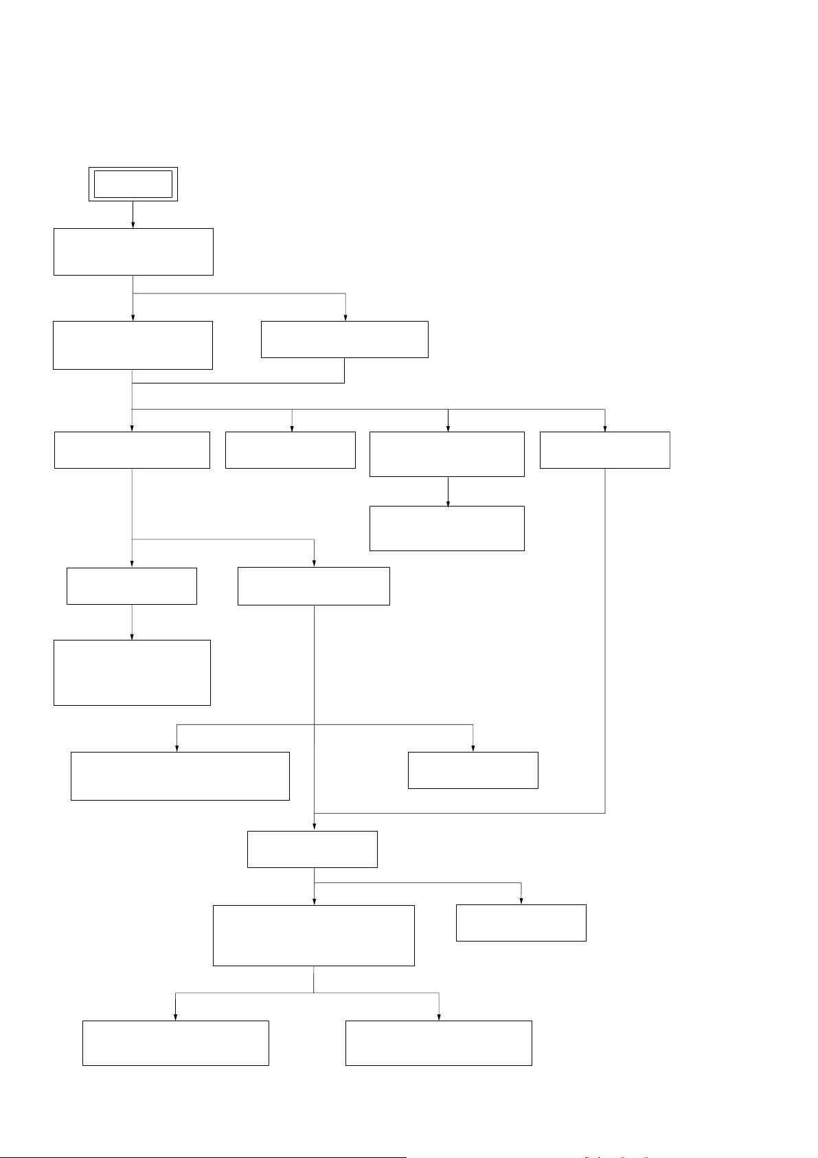
3-1. DISASSEMBLY FLOW
•This set can be disassembled in the order shown below.
SET
3-2. SIDE PANEL (R) ,
SIDE PANEL (L)
(Page 9)
3-3.
TOP PANEL ASSY
(EXCEPT US, CND)
(Page 10)
3-4.
TOP PANEL (US, CND)
SECTION 3
DISASSEMBLY
(Page 10)
3-5.
FRONT PANEL ASSY
(Page 11)
3-8. KEY-LEFT BOARD
(Page 13)
3-9. KEY-RIGHT BOARD,
KEY-CD BOARD,
PANEL BOARD
(Page 13)
3-13. OPTICAL PICK-UP (KSM-213DCP),
BD90 BOARD
(Page 17)
3-10. JACK BOARD
3-12. CD MECHANICAL
(Page 14)
(Page 16)
3-6. MECHANICAL DECK
(EXCEPT US, CND)
(Page 12)
3-7.
BELT (MAIN), BELT (R/F)
(EXCEPT US, CND)
(Page 12)
3-14. BELT (DLM3A)
(Page 18)
3-11. MAIN BOARD
(Page 15)
3-15. CHASSIS
(Page 18)
3-16. PT BOARD (EXCEPT EC55:US),
3-17. LOW-AMP BOARD,
HI-AMP BOARD (EC77/GX99)
(Page 19)
PT (U) BOARD (EC55:US),
POWER TRANSFORMER
(Page 19)
3-18. HI-AMP BOARD (EC55)
(Page 20)
3-19. DC FAN
(Page 20)
8
)
Note: Follow the disassembly procedure in the numerical order given.
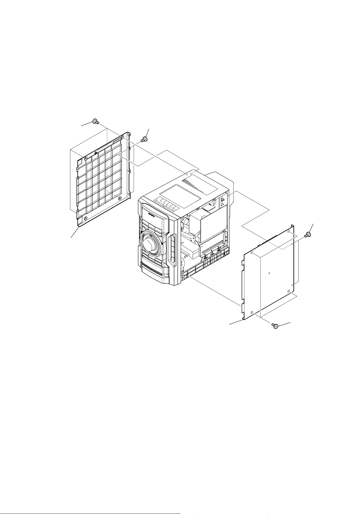
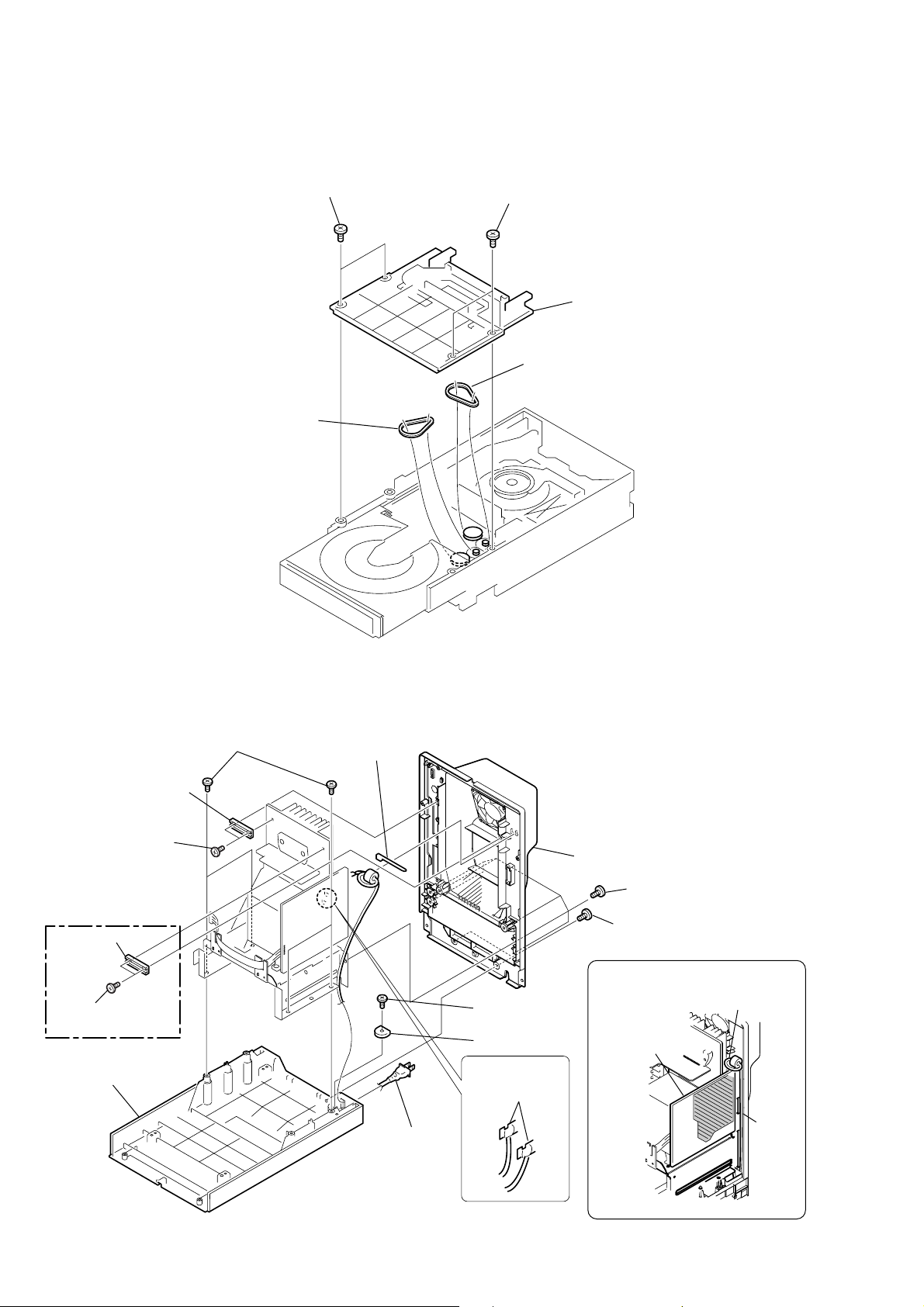
3-2. SIDE PANEL (R), SIDE PANEL (L)
5
two screws
4
four screws
(TP3
(+BVTP3
×
12
)
×
10
)
HCD-EC55/EC77/GX99
6
side panel (L)
3
side panel (R)
2
1
four screws
(TP3
two screws
(+BVTP3
×
12
)
×
10
9
HCD-EC55/EC77/GX99
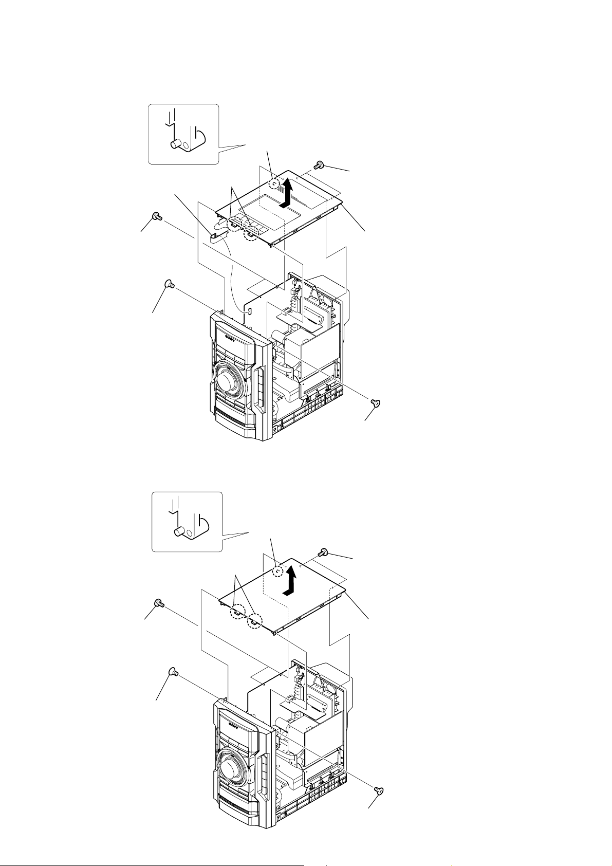
3-3. TOP PANEL ASSY (EXCEPT US, CND)
6
two
claws
3
two screws
(+BVTP3
5
wire (flat type)
9core (CN606)
×
10
)
2
screw
(+KTP3
×
10
)
7
dowel
4
two screws
(+BVTP3
8
in the direction of the arrow.
×
10
)
Remove the top panel assy
3-4. TOP PANEL (US, CND)
3
two screws
(+BVTP3
2
screw
(+KTP3
×
10
1
screw
(+KTP3
×
10
)
6
dowel
4
5
two
claws
)
×
10
)
two screws
(+BVTP3
7
in the direction of the arrow.
×
10
)
Remove the top panel
10
1
screw
(+KTP3
×
10
)

3-5. FRONT PANEL ASSY
1
Turn the bottom rib (not the gear) with a flathead screwdriver in the direction
of arrow A, and draw out the tray in the direction of arrow B.
B
tray
gear
HCD-EC55/EC77/GX99
A
flathead screwdriver
3
door
(CD)
2
two claws
bottom rib
9
front panel
assy
4
fwire (flat type)
27core (CN607)
5
fwire (flat type)
9core (CN605)
8
screw
(+KTP3
×
10
)
7
screw
(+KTP3
×
10
)
6
wire (flat type)
13core (CN302)
11
HCD-EC55/EC77/GX99
3-6. MECHANICAL DECK (EXCEPT US, CND)
1
Open the cassette box.
7
Slide the lever in the
direction of the arrow.
2
four screws
(+BVTP 2.6 × 8)
8
mechanical deck
5
(CN501)
6
connector
DECK board
3
two screws
(+BVTP 3 × 6)
3-7. BELT (MAIN), BELT (R/F) (EXCEPT US, CND)
1
belt (MAIN)
4
bracket (DECK)
2
belt (R/F)
12
3-8. KEY-LEFT BOARD
9
claw
8
eight screws
(+BVTP 2.6
×
8
)
4
six screws
(+BVTP 2.6
×
8
)
6
KEY-CD board
3
KEY-RIGHT board
5
Remove the
soldering.
1
five screws
(+BVTP 2.6
×
8
)
0
wire (flat type)
27core (CN301)
qa
PANEL board
2
connector
(CN403)
7
knob (VOL)
HCD-EC55/EC77/GX99
2
connector
(CN401)
3
KEY-LEFT board
1
four screws
(+BVTP 2.6
×
8
)
3-9. KEY-RIGHT BOARD, KEY-CD BOARD, PANEL BOARD
13
HCD-EC55/EC77/GX99
3-10. JACK BOARD
4
JACK board
2
JACK HOLD board
1
three screws
(+BVTP 2.6 × 8)
3
wire (flat type)
9core (CN605)
14

3-11. MAIN BOARD
7
two screws
(+BVTP3
×
6
HCD-EC55/EC77/GX99
8
screw
qa
Remove the soldering.
qd
MAIN board
)
(+BVTP3
×
10
)
qs
REG board
3
wire (flat type)
21core (CN608)
4
connector
(CN601)
(EC77/GX99)
6
two screws
(+BVTP3
2
wire (flat type)
27core (CN607)
1
wire (flat type)
9core (CN605)
9
two screws
(+BVTP3
0
×
10
)
5
(CN604)
two screws
(+BVTP3
connector
×
10
)
×
10
)
15

HCD-EC55/EC77/GX99
)
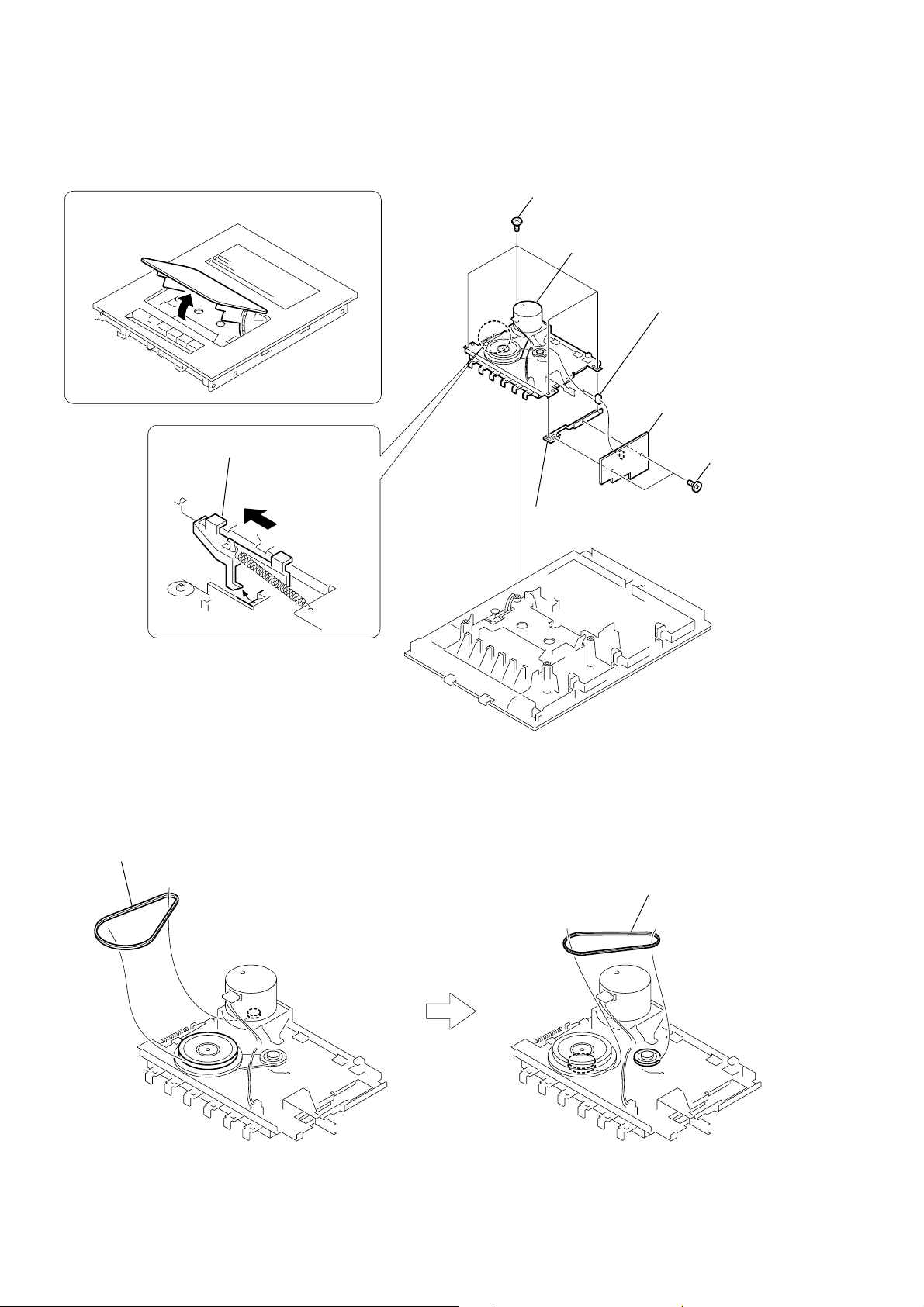
3-12. CD MECHANICAL
1
wire (flat type)
21core (CN608)
3
Remove the CD mechanical in the direction of the arrow.
5
13core
wire (flat type)
2
four screws
(+BVTP3
8
CD mechanical
4
21core
×
10
wire (flat type
)
16
(EC77:US,CND/GX99)
7
6
two tapping screws
(+BVWH 3
cover (DLM3)
×
8
)

3-13. OPTICAL PICK-UP (KSM-213DCP), BD90 BOARD
8
Remove the solderings from
the four points.
7
wire (flat type) (16 core)
(CN301)
q;
BD90 board
9
optical pick-up
(KSM-213DCP)
4
two screws
(+PTPWHM 2.6)
1
two screws
(+PTPWHM 2.6)
2
two coil springs (insulator)
3
two insulators
5
two coil springs (insulator)
6
two insulators
HCD-EC55/EC77/GX99
17
HCD-EC55/EC77/GX99
3-14. BELT (DLM3A)
5
belt (DLM3A)
1
two screws
2
two screws
4
3
cover
belt (DLM3A)
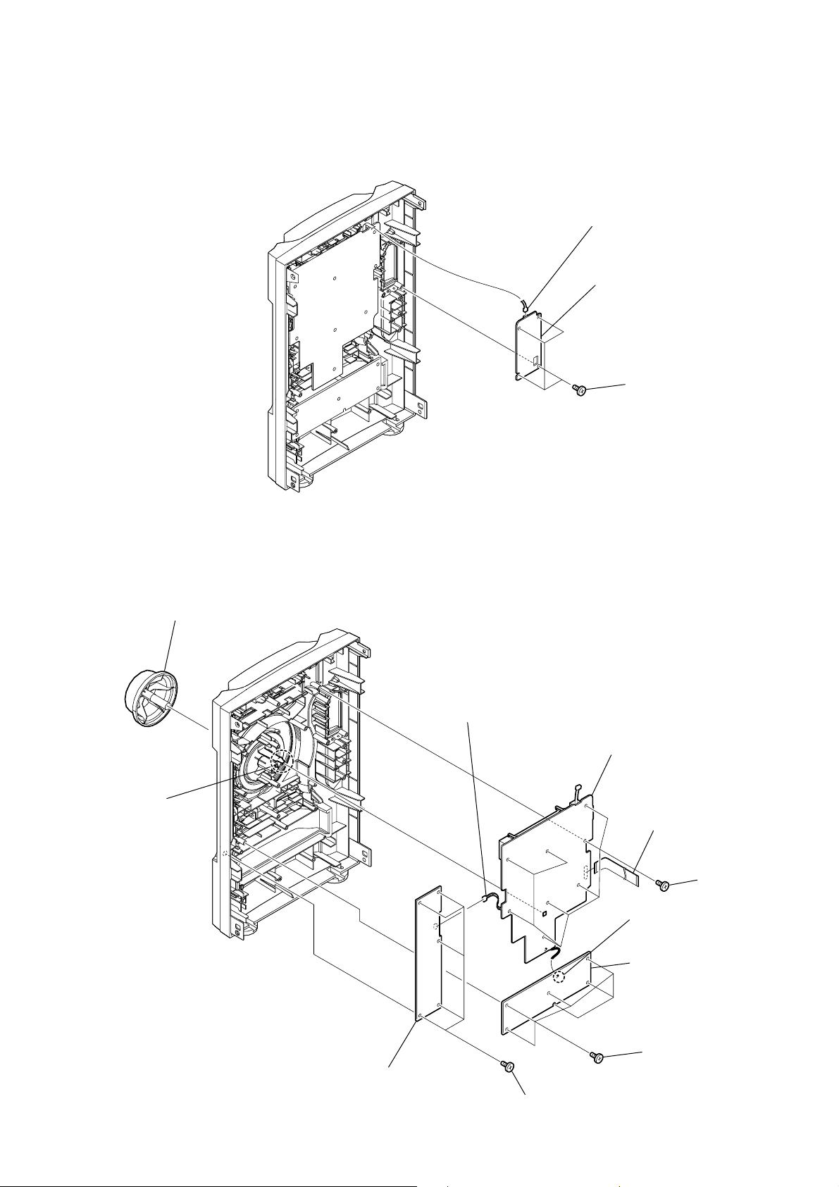
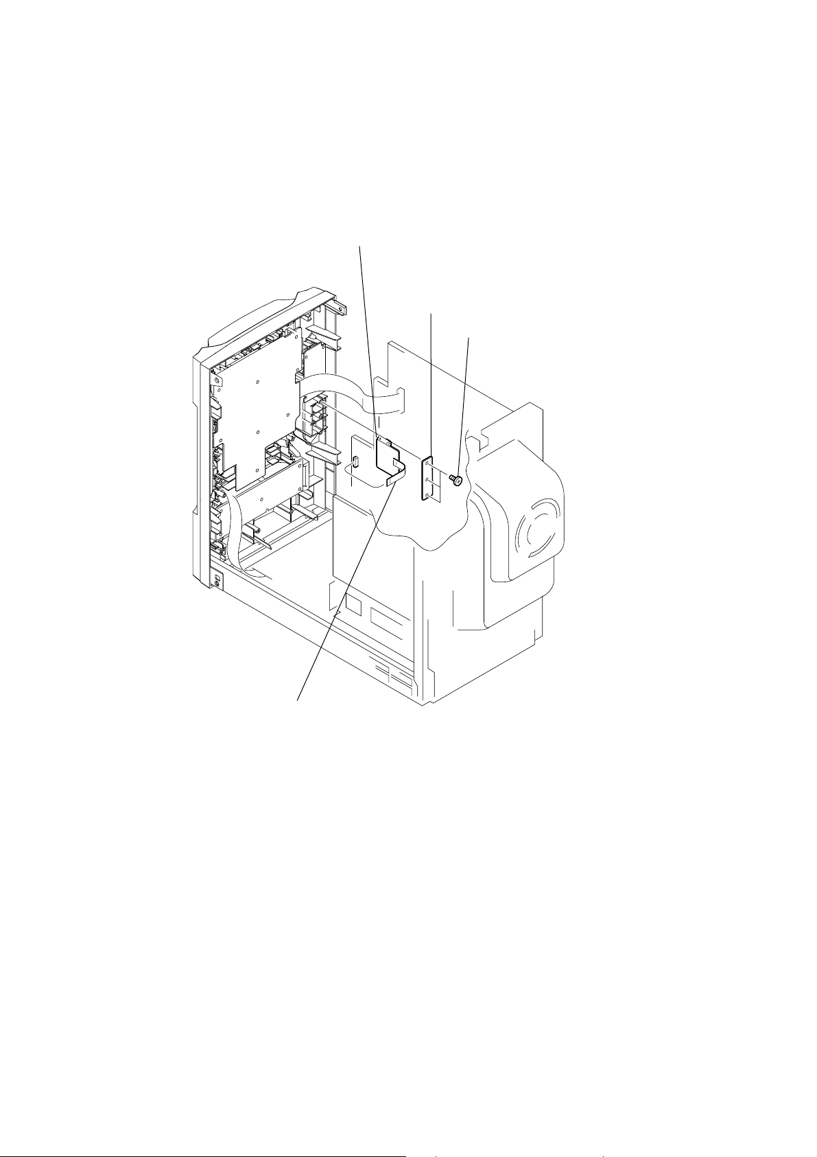
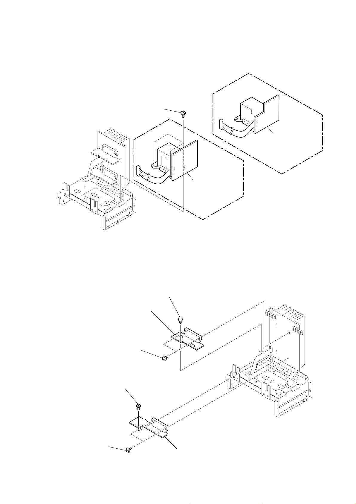
3-15. CHASSIS
5
heatsink support
4
two screws
(+BVTP3
(EC77/GX99)
7
heatsink support
6
two screws
(+BVTP3
qa
×
10
chassis
0
four screws
(+BVTP4
×
10
)
)
×
12
)
1
clamp
qf
POWER cord
qs
screw
(+BVTP3
qd
HOLD board
9
Remove the
solderings.
8
back panel
3
six screws
(+BVTP3
2
two screws
(+BVTP3
Route the harnesses as shown below.
×
10
)
PT board
×
10
×
10
)
)
power cord
groove
18
HCD-EC55/EC77/GX99
3-16. PT BOARD (EXCEPT EC55:US), PT (U) BOARD (EC55:US), POWER TRANSFORMER
1
four screws
(+BV4
×
8
)
2
PT (U) board,
power transformer
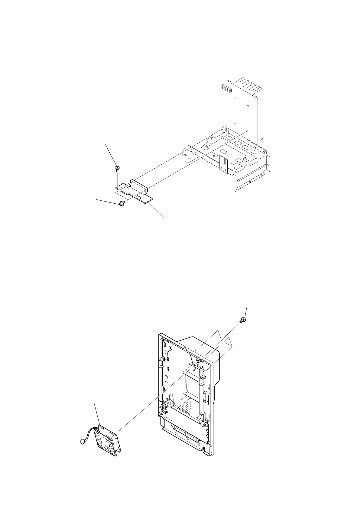
3-17. LOW-AMP BOARD, HI-AMP BOARD (EC77/GX99)
1
screw
3
HI-AMP board
2
two transisitor
screws
(+BVTP3
×
10
)
2
PT board,
power transformer
(EXCEPT EC55:US)
(EC55:US)
5
two transisitor
screws
4
screw
(+BVTP3
×
10
)
6
LOW-AMP board
19
HCD-EC55/EC77/GX99
)
3-18. HI-AMP BOARD (EC55)
1
screw
(+BV3
×
10
)
3-19. DC FAN
2
two transisitor
screws
3
HI-AMP board
1
four screws
(+BVTP3
×
10
20
2
DC fan

SECTION 4
TEST MODE
HCD-EC55/EC77/GX99
Ver. 1.1
[MC COLD RESET]
The cold reset clears all data including preset data stored in the
memory to initial conditions. Execute this mode when returning
the set to the customer.
Procedure:
1. In the standby status, press the @/1 button to turn the power
on.
2. Press three buttons of PLAY MODE/TUNING MODE ,
FUNCTION and at last @/1 simultaneously.
3. When “RESET” appears, the machine enters standby status.
[PANEL TEST MODE]
Enter The Panel Test Mode
Procedure:
1. In the standby status, press the @/1 button to turn the power
on.
2. Press three buttons of DISPLAY , x , and TUNER/BAND
simultaneously.
3. When the panel test mode is activated, LEDs and segments of
LCD are all turned on.
Version Check
Procedure:
1. In the panel test mode (all LEDs and segments of LCD are
turned on), press the FUNCTION button.
2. On the LCD, date and version are displayed “xxxxxxxx”.
For example, “0904V014”.
3. From this status, press the TUNER/BAND button, and the
destination is displayed. For example, “ER NA” or “ER E2”
4. To release from this mode, press three buttons of DISPLAY ,
x , and TUNER/BAND simultaneously.
[CD REPEAT 5 LIMIT CANCEL MODE]
Number of repeats for CD playback is 5 times when the repeat mode
is “REPEA T”. This mode enables CD to repeat playback for limitless
times.
Procedure:
1. Press the @/1 button to turn the power on.
2. Press the FUNCTION button to select CD function.
3. Press three buttons of CD u , DSGX , and DISPLAY
simultaneously.
4. It enters the CD repeat 5 limit cancel mode and displays “NO
LIMIT”
5. To release this mode, press the @/1 button to turn the power
off.
[CD SHIP MODE]
This mode can run the CD sled motor optionally. Use this mode, for
instance, when cleaning the optical pick-up.
Procedure:
1. Press the @/1 button to turn the power on.
2. Press the FUNCTION button to select CD function.
3. Press two buttons of CD u and @/1 simultaneously.
4. Set to the CD ship mode. (chucking on)
5. After blink “STANDBY”, “LOCK” is displayed, disconnect
the AC plug.
[CD SLOT LOCK]
This mode is for the antitheft of CD disc in shop. (not for transport)
Procedure:
1. Press the @/1 button to turn the power on.
2. Press the FUNCTION button to select CD function.
3. Insert a disc.
4. While pressing the x button, press the Z button for more 5
seconds.
5. The message “LOCKED” is displayed and the disc slot is
locked. (Even if exiting from this mode, the disc slot is still
locked)
6. If press the Z button to eject the disc, the message
“LOCKED” is displayed and can not eject the disc.
7. To release this lock, while pressing the x button, press the
Z button for 5 seconds again.
8. The message “UNLOCKED” is displayed and the disc slot is
unlocked.
[CD POWER MANAGE]
This mode is for switch the CD power supply on/off. Even if this
state pulls out AC plug, it is held.
Procedure:
1. Press the @/1 button to turn the power on.
2. Press the FUNCTION button to select CD function.
3. Press the @/1 button again to turn the power off (standby).
4. After pressing the DISPLAY button, while pressing the x
button, press the @/1 button.
5. It turns power on and display “CD POWER”, then display
“ON” or “OFF”.
[CHANGE-OVER THE AM TUNING INTERVAL]
(Except European and Russian models)
The AM tuning interval can be changed over 9 kHz or 10 kHz.
Procedure:
1. Press the @/1 button to turn the power on.
2. Press the TUNER/BAND button to select TUNER (AM)
function.
3. Press the @/1 button again to turn the power off (standby).
4. After pressing the DISPLAY button, while pressing the
TUNING+
5. It turns power on and display “9k STEP” or “10k STEP”, and
thus the tuning interval is changed over.
ML
button, press the @/1 button.
[CD SHIP AND COLD RESET]
Procedure:
1. Press the @/1 button to turn the power on.
2. Press the FUNCTION button to select CD function.
3. Press three buttons of PLAY MODE/TUNING MODE ,
CD u and @/1 simultaneously.
4. After blink “STANDBY”, “RESET” is displayed, disconnect
the AC plug.
21

HCD-EC55/EC77/GX99
[CD SERVO TEST MODE]
This mode can check the servo system operations of the optical
pick-up system (= optical unit + BD board).
Note1: Do not enter the [CD SERVO TEST MODE] while any other test
mode is in progress.
Note2: Do not enter any other test mode while the [CD SERVO TEST
MODE] is in progress.
How to Enter the CD Servo Test Mode
Procedure:
1. Press the @/1 button to turn the power on.
2. Press the FUNCTION button to select CD function.
3.
Press three buttons of CD u , PLAY MODE/TUNING MODE
and DISPLAY simultaneously.
4. It enters the CD servo test mode and displays “BDT S CU”.
How to Exit from the CD Servo Test Mode
Procedure:
1. Press three buttons of CD u , PLA Y MODE/TUNING MODE
and DISPLAY simultaneously.
2. It exits from the CD Servo Test Mode and returns to the
ordinary CD function.
Key Operation:
+ , – : Use these keys to move between the five modes
contained in the CD Servo Test Mode, that are the
S-Curve Mode, the RAM Read Mode, the RAM
Write Mode, the Command Out Mode and the Error
Rate Mode as described below . Also, use these keys
to move between the menus within the respective
five modes. When + is pressed, the screen
advances to the next menu or to the next mode. When
– is pressed, the screen returns back to the
previous menu or to the previous mode. Use these
keys also to increase or decrease the numeric value
when changing the numeric value. Pressing +
increases the value and pressing – decreases the
value.
DSGX , EQ :Use these keys to move between the different layers
of the hierarchy of the CD Servo Test Mode shown
below. Press DSGX to move down to the lower
layer, and press EQ to move up to the higher layer.
TUNING+
FUNCTION :Use this key to execute Command Out in the
ML
,
lm
–TUNING :
Use these keys to move the cursor to the right digit
or to the left digit in the six-digit number, when
changing the numeric value.
Press TUNING+
the right, and press
ML
lm
to move the cursor to
–TUNING to return
the cursor to the left.
Command Out Mode.
CD Servo Test Mode Tree:
S Curve Mode LD ON
(BDT S CU) (LD ON)
RAM Read Mode
(BDTRAM R) (DISCTYPE) (0000)
Gain Index value indication
(GAININDX) (0001)
RFO GAIN value indication
(RFO_GAIN) (0009)
FEO GAIN value indication
(FEO_GAIN) (0005)
SBAD GAIN value indication
(SBAD_GAI) (0007)
TEO GAIN value indication
(TEO_GAIN) (0000)
Disc Size value indication
(DISCSIZE) (0000)
(OPABRKER) (0000)
SBBT Data value indication
(SBBT DAT) (006B)
FEOOCD value indication
(FEOOCD) (F780)
RAM Write Mode
(BDTRAM W) (00 SPG) (Non mask:00, Mask:01)
Fix RF Gain value edit
(00 FIX) (Non Fix:00, AL Fix:01, RW Fix:02)
TMAX ON value edit
(00 TMA)
Driver Mute OFF value edit
(00 D_M) (Normal:00, Forced OFF:01)
Command Out Mode
(BDT COMO) (COMOUT6X) (000000) (OK)
READ2X value edit command out
(READ2X) (60) (50)
REG READ value edit command out
(REG_READ) (00) (0000)
FEBC? command out
(FEBC?) (00)
FGADD? command out
(FGADD?) (10)
TEBC? command out
(TEBC?) (00)
TGADD? command out
(TGADD?) (00)
RFGC? command out
(RFGC?) (00)
FEOF? command out
(FEOF?) (FFC0)
TEOF? command out
(TEOF?) (FFC0)
TEIOCD1? command out
(TEIOCD1?) (FE80)
TEIOCD2? command out
(TEIOCD2?) (FF40)
TEIOCD3? command out
(TEIOCD3?) (FFC0)
TEOOCD? command out
(TEOOCD?) (FD00)
FEOOCD? command out
(FEOOCD?) (F780)
MONITOR value edit command out
(MONITOR) (570A00) (OK)
Error Rate Mode Error rate indication
(BDT ERR) (00000000)
Higher layer Lower layer of menu hierarchy
Disc Type value indication
Op ABRAKE Error
SPG Mask value edit
COMOUT6X value edit command out
value indication
22

HCD-EC55/EC77/GX99
[CD SERVICE MODE]
This mode can move the SLED of the optical pick-up, and also can
turn the optical pick-up laser power on and off.
Procedure:
1. Press the @/1 button to turn the power on.
2. Press three buttons of CD u ,
simultaneously.
4. It enters the CD service mode and displays “SERVICE”.
5. To exit from this mode, press three buttons of CD u ,
and DISPLAY simultaneously.
Key Operation:
TUNING+
PLAY MODE/TUNING MODE :
ML
,
lm
Use these keys to move the SLED. When
TUNING+
SLED moves to outer circumference and the message
“SLED OUT” is displayed.
When
lm
the SLED moves to inner circumference and the
message “SLED IN” is displayed.
Use this key to turn the optical pick-up laser power
on and off. When the laser power is turned on, the
message “LD ON” is displayed. When the laser
power is turned off, the message “LD OFF” is
displayed.
–TUNING :
ML
is pressed in this mode, the
–TUNING is pressed in this mode,
+ , and DISPLAY
[CD ERROR CODE]
The past errors of the CD mechanism (CDM) are displayed as the
CDM Errors, and those of the optical pick-up system (= optical unit
+ BD board) are displayed as the BD Errors as shown below.
Procedure:
1. Press the @/1 button to turn the power on.
2. Press the FUNCTION button to select CD function.
3. Press three buttons of CD u , x and DISPLAY
simultaneously.
4. Then, the CDM error code is displayed as “M0xxxxxx” (x
means hexadecimal number) on the LCD screen as shown
below.
5. Every pressing of the TUNING+
increments the number after “M” starting from “M0” up to
“M9”, and then returns to “M0”. Every pressing of the
lm
number after “M”. The smaller the error code number is, the
newer the error content is.
6. When the PLAY MODE/TUNING MODE b utton is pressed
then, the BD error code is displayed as “D0xxxxxx” (x means
hexadecimal number) on the LCD screen as shown below. In
the same way as the CDM error code, use of the
TUNING+
this mode enables tracing of the error history.
7. To exit from this mode, press the @/1 button to turn the
power off.
–TUNING button in this mode decrements the
ML
and the
ML
lm
button in this mode
–TUNING buttons in
Contents of “CDM Errors”
Error display example
M
0 FF 11 42
1 234
1 It indicates the error history number
0 to 9: The error code number 0 indicates the newest error.
+
2 It indicates whether the CDM error occurs in the normal
operations or during the initialization operation.
FF : The error has occurred in the normal
Other than FF : The error has occurred during the initialization
3 It indicates the processing during which the trouble has
occurred.
01: The disc EJECT processing is in progress.
02: The disc INSERTION-WAITING processing is in
progress.
03: Processing of the disc INSERTION-REQUEST for the
upper CD tray is in progress.
04: Processing of the disc EJECTION-REQUEST for the
upper CD tray is in progress.
05: The disc pulling-in operation is in progress.
06: The disc chucking processing is in progress.
07: The disc re-chucking processing is in progress.
08: The disc chucking-release completion operation is in
progress.
4 It indicates the operation during which the trouble has occurred.
00 : Waiting for the operation.
10 to 13 : The disc EJECT operation is in progress.
20 : The disc pulling-in operation is in progress.
30 : The disc chucking-release operation is in progress.
40 to 43 : The disc EJECT operation due to error is in progress.
Contents of “BD Errors”
Error display example
D 0 02 09 01
1 234
1 It indicates the error history number
0 to 9: The error code number 0 indicates the newest error.
2 It indicates the error content
01: The focus servo cannot lock-in.
02: GFS is no good (NG).
03: The startup time exceeds the specified period of time (time
over)
04: The focus servo is unlocked continuously.
05: Q code cannot be obtained within the specified period of
time.
06: The tracking servo cannot lock-in.
07: Blank disc
operations.
operation.
23

HCD-EC55/EC77/GX99
3 It indicates the on-going processing of optical pick-up system
(= optical unit + BD board) when the trouble has occurred.
01: The CD SHIP mode processing is in progress.
02: The POWER OFF processing is in progress.
03: The INITIALIZE processing is in progress.
04: The optical pick-up system (= optical unit + BD board)
is in the stop state.
05: The STOP operation is in progress.
06: The startup processing is in progress.
07: The TOC read-in processing is in progress.
08: The SEARCH operation is in progress.
09: The PLAY operation is in progress.
0A: The PAUSE operation is in progress.
0B: The PLAY – MANUAL SEARCH operation is in
progress.
0C: The PAUSE – MANUAL SEARCH operation is in
progress.
4 It indicates the operation that is being processed when the
trouble has occurred.
It indicates the step number of each processing specified by
3. Because the numbers of steps are different in each
processing, this number is different in each processing.
24

Screw
position
L-CH
peak
within
1dB
Output
level
L-CH
peak
R-CH
peak
within
1dB
Screw
position
R-CH
peak
set
JACK board
PHONES jack
(J402)
+
–
level meter
test tape
P-4-A063
(6.3 kHz, −10 dB)
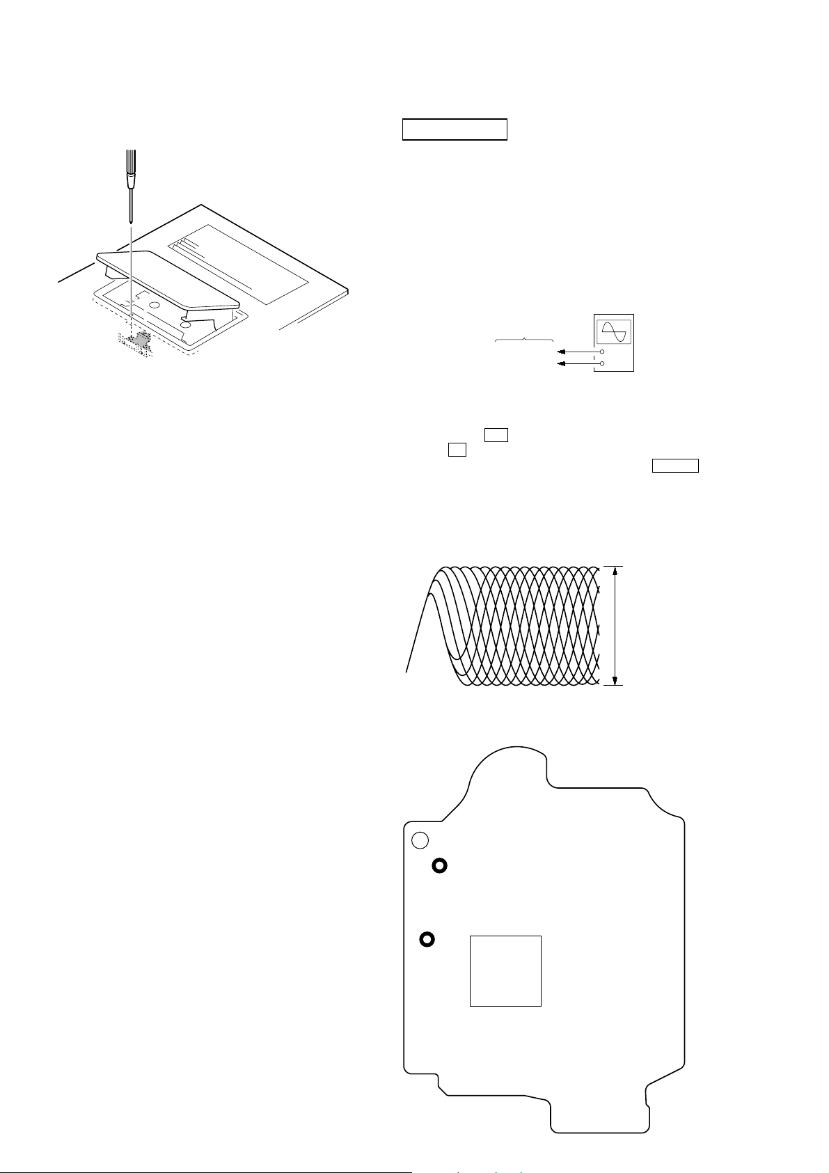
SECTION 5
MECHANICAL ADJUSTMENTS
HCD-EC55/EC77/GX99
SECTION 6
ELECTRICAL ADJUSTMENTS
• Precaution
1. Clean the following parts with a denatured-alcohol-moistened
swab :
record/playback head pinch roller
erase head rubber belts
capstan idlers
2. Demagnetize the record/playback head with a head
demagnetizer. (Do not bring the head magnetizer close to the
erase head.)
3. Do not use a magnetized screwdriver for the adjustments.
4. After the adjustments, appiy suitable locking compound to
the parts adjusted.
5. The adjustments should be performed with the rated power
supply voltage unless otherwise noted.
• Torque Measurement
Mode
FWD
FWD
back tension
FF
REW
Torque meter
CQ-102AS
CQ-102C
CQ-201AS
CQ-201B
Meter reading
2.0 – 8.0 mN • m
(20 to 80 g • cm)
(0.28 – 1.12 oz • inch)
0.15 – 0.6 mN • m
(1.5 to 6 g • cm)
(0.021 – 0.083 oz • inch)
5 – 17.7 mN • m
(50 to 177 g • cm)
(0.7 – 2.48 oz • inch)
5 – 17.7 mN • m
(50 to 177 g • cm)
(0.7 – 2.48 oz • inch)
• Tape T ension Measurement
Mode Tension Meter Meter Reading
FWD CQ-403A
more than 80 g
(more than 2.82 oz)
DECK SECTION (EXCEPT US, CND)
0 dB=0.775 V
1. Demagnetize the record/playback head with a head
demagnetizer.
2. Do not use a magnetized screwdriver for the adjustments.
• Test T ape
Tape Signal Used for
P-4-A063 6.3 kHz, -10 dB Azimuth Adjustment
RECORD/PLA YBA CK HEAD AZIMUTH ADJUSTMENT
Procedure:
1. Mode: Playback
2. Turn the adjustment screw and check output peaks. If the peaks
do not match for L-CH and R-CH, turn the adjustment screw
so that outputs match within 1dB of peak.
3. Mode: Playback
test tape
P-4-A063
(6.3 kHz, −10 dB)
in phase 45° 90° 135° 180°
4. After the adjustments, apply suitable locking compound to
JACK board
PHONES jack
(J402)
set
waveform of oscilloscope
good
oscilloscope
V
wrong
H
the pats adjusted.
25
HCD-EC55/EC77/GX99
Adjustment Location: Record/Playback/Erase Head
CD SECTION
Note:
1. CD Block is basically constructed to operate without adjustment.
2. Use YEDS-18 disc (3-702-101-01) unless otherwise indicated.
3. Use an oscilloscope with more than 10 MΩ impedance.
4. Clean the object lens by an applicator with neutral detergent when the
signal level is low than specified value with the following checks.
5. Check the focus bias check when optical pick-up block is replaced.
FOCUS BIAS CHECK
oscilloscope
(DC range)
BD90 board
TP (RFI)
TP (VC)
Procedure :
1. Connect oscilloscope to TP (RFI) and TP (VC) on the BD90
board.
2. Press the I/1 button to turn the power ON, and press
the Z (CD) button to open the CD disc tray.
3. Set disc (YEDS-18) on the tray and press the CD u button
to playback.
4. Confirm that oscilloscope waveform is as shown in the figure
below. (eye pattern)
A good eye pattern means that the diamond shape (◊) in the
center of the waveform can be clearly distinguished.
+
–
Checking Location:
– BD90 Board (Side B) –
TP
(VC)
TP
(RFI)
IC101
VOLT/DIV: 200 mV
TIME/DIV: 500 ns
level:
0.5 to 0.8 Vp-p
26

HCD-EC55/EC77/GX99
r
FM RF signal
generator
Carrier frequency: 98MHz
Modulation:
deviation by FM 75 kHz
Output level: 60 dBuV
+
–
level meter
MAIN board
TP(TUNER-GND)
MAIN board
IC801 pin qs
(TUNER OUT L-ch)
set
MAIN board
ANTENNA
CN801 pin 2
MAIN board
ANTENNA
CN801 pin 3
Ver. 1.1
TUNER SECTION 0 dB=1 µV
[AM]
Setting:
FUNCTION: TUNER
TUNER/BAND button: AM
60 cm
loop antenna A
AM RF signal
generator
30% amplitude
modulation by
400 Hz signal
Output level: 54 dBuV
[FM]
Setting:
FUNCTION: TUNER
TUNER/BAND button: FM
FM RF signal
generator
0.01 µF
75kHz frequency
deviation by 1K Hz
signal
Output level: as low as possible
(8dBuV)
loop antenna B
set
MAIN board
ANTENNA
CN801 pin 12
MAIN board
ANTENNA
CN801 pin 3
set
MAIN board
ANTENNA
CN801 pin 2
level mete
32 Ω
JACK board
PHONES jack (J402)
32 Ω
JACK board
PHONES jack (J402)
+
–
level meter
+
–
AM FREQUENCY COVERAGE ADJUSTMENT
(US, Canadian, Australian models)
Adjustment Part Frequency Display Reading on Digital Voltmeter
L801 530 kHz 1.5 ± 0.1 V
Confirmation 1,710 kHz 8 ± 0.5 V
AM FREQUENCY COVERAGE ADJUSTMENT (Other models)
Adjustment Part Frequency Display Reading on Digital Voltmeter
L801 531 kHz 1.5 ± 0.1 V
Confirmation 1,602 kHz 7.2 ± 0.5 V
AM TRACKING ADJUSTMENT (US, Canadian, Australian models)
Adjust for a maximum reading on level meter
L805 530 kHz
AM TRACKING ADJUSTMENT (Other models)
Adjust for a maximum reading on level meter
L805 531 kHz
FM FREQUENCY COVERAGE ADJUSTMENT
Adjustment Part Frequency Display Reading on Digital Voltmeter
L803 87.5 kHz 1.75 ± 0.1 V
Confirmation 108 kHz 6.2 ± 0.5 V
FM TRACKING ADJUSTMENT
Adjust for a maximum reading on level meter
L804 98 MHz
Adjustment Location: MAIN board (See page 28).
digital voltmeter
MAIN board
TP (TUNER VT)
100 kΩ
•Repeat the procedures in each adjustment several times.
[FM DETECTOR ADJUSTMENT]
Setting:
FUNCTION: TUNER
TUNER/BAND button: FM
1. Tune the set to 98 MHz.
2. Adjust L802 so that modulation distortion may become the
best in the vicinity of the maximum value where the tuner out
level becomes –15dBuV or more.
27

HCD-EC55/EC77/GX99
[FM Auto Stop Check]
generator
SET
+
75 Ω
Procedure:
1. Turn the power on.
2. Input the following signal from Signal Generator to FM
antenna input directly.
* Carrier Freq: A = 87.5 MHz, B = 98 MHz, C = 108 MHz
Deviation : 75 kHz
Modulation : 1 kHz
ANT input : 35 dBu (EMF)
Note: Please use 75 ohm “coaxial cable” to connect SG and the set. You
cannot use video cable for checking.
Please use SG whose output impedance is 75 ohm.
3. Set to FM tuner function and scan the input FM signal with
automatic scanning.
4. Confirm that input Frequency of A, B and C are detected and
automatic scanning stops.
The stop of automatic scanning means “The station signal is received
in good condition.”
Adjustment Location and Connecting Points
– MAIN BOARD (Component Side) –
AM Tracking
Adjustment
FM Frequency
L803
Coverage Adjustment
AM Frequency
Coverage Adjustment
JW801
FM Detector
L802
Adjustment
– MAIN BOARD (Conductor Side) –
CN801
3
FM
ANTENNA
1
AM
L805
L801
CN801
ANTENNA
L804
FM Tracking
Adjustment
3
FM
1
AM
IC801 pin wk
(TUNER VT)
28
36
IC801
1
12
IC801 pin qs
(TUNER OUT L-ch)
JW801
19
18
TUNER-GND
28

SECTION 7
DIAGRAMS
HCD-EC55/EC77/GX99
Ver. 1.1
THIS NOTE IS COMMON FOR PRINTED WIRING BOARDS AND SCHEMATIC DIAGRAMS.
(In addition to this, the necessary note is printed in each block.)
Note on Schematic Diagram:
• All capacitors are in µF unless otherwise noted. (p: pF)
50 WV or less are not indicated except f or electrolytics and
tantalums.
• All resistors are in Ω and
specified.
• f : internal component.
• 2 : nonflammable resistor.
• 5 : fusible resistor.
• C : panel designation.
Note:
The components identified by mark 0 or dotted line with mark 0 are
critical for safety.
Replace only with part
number specified.
• H : adjustment for repair.
• A : B+ Line.
• B : B– Line.
•Voltages are taken with a VOM (Input impedance 10 MΩ).
Voltage variations may be noted due to normal production
tolerances.
•Waveforms are taken with a oscilloscope.
Voltage variations may be noted due to normal production
tolerances.
– HI-AMP/LOW-AMP Section –
No mark: CD STOP
– DECK Section –
No mark: TAPE PLAY or TAPE REC
– Other Section –
No mark: CD PLAY
• Circled numbers refer to waveforms.
• Signal path.
F : TUNER (FM)
J : TUNER (AM)
f : CD
d : AUDIO
E : PB (TAPE)
a : REC (TAPE)
•Abbreviation
AR : Argentine model
AUS: Australian model
CND : Canadian model
E2 : 120 V AC area in E model
E3 : 240 V AC area in E model
E51 : Chilean and Peruvian models
KR : Korean model
MX : Mexican model
RU : Russian model
SP : Singapore model
1
4
/
W or less unless otherwise
Note:
Les composants identifiés
par une marque 0 sont critiques pour la sécurité.
Ne les remplacer que par une
piéce portant le numéro
spécifié.
Note on Printed Wiring Boards:
• X : parts extracted from the component side.
• Y : parts extracted from the conductor side.
• f : internal component.
•
• Indication of transistor.
: Pattern from the side which enables seeing.
Caution:
Pattern face side: Parts on the pattern face side seen from
(Side B) the pattern face are indicated.
Parts face side: Parts on the parts face side seen from
(Side A) the parts face are indicated.
C
Q
B
E
B
These are omitted.
Q
CE
These are omitted.
• Circuit Boards Location
EC77/GX99
KEY-LEFT board
REG board
JACK board
EC55
KEY-LEFT board
DECK board (EXCEPT US, CND)
PANEL board
KEY-CD board
DECK board (EXCEPT US)
PANEL board
HI-AMP board
MAIN board
LOW-AMP board
PT board
BD90 board
KEY-RIGHT board
HI-AMP board
MAIN board
PT board (EXCEPT US)
HCD-EC55/EC77/GX99
PT (U) board (US)
REG board
JACK board
BD90 board
KEY-CD board
KEY-RIGHT board
2929

HCD-EC55/EC77/GX99
7-1. BLOCK DIAGRAM — BD/DRIVER SECTION —
OPTICAL PICK-UP
BLOCK
(KSM-213DCP)
DETECTOR
VCC
FOCUS
COIL
TRACKING
COIL
M401
(SPINDLE)
M402
(SLED)
15
16
VC
12
A
11
B
10
C
13
D
14
E
F
LD
GND
PD
VR
F+
F
T+
T
SP+
M
SP
SL+
+1.7V
+3.3V
95
FN11(A)
97
FP11(B)
94
FN12(C)
96
FP12(D)
100
9
Q301
AUTOMATIC
7
8
5
6
4
1
3
2
POWER
CONTROLLER
IC401
SL/SP MOTOR
DRIVER
FOCUS/TRACKING
COIL DRIVER
26
VD4+
27
VD4-
18
VD3+
17
VD3-
2
VO1+
1
VO1-
12
VO2-
IN1
IN2'
IN3'
BIAS
IN4'
3
9
20
23
24
X102
16.934MHz
+3.3V
S201
(LIMIT)
98
91
24
23
42
20
13
12
10
11
9
TN1(E)
TP1(F)
LDo
XO
XI
MD1
IOO(/MSO)
DMO
FMO
TRo
VREF
F0o
M
11
SL
VO2+
MUTE
21
7
I01(/UHS0)
IC101
RF AMP,DSP,MP3
BUCK(CLK)
BUS0
BUS1
BUS2
BUS3
RST
CCE
P100
SBSY
ZDET
RO
SYSTEM CONTROLLER
IC301
(1/2)
CD MECHANISM DECK
IC201
+1.5V
38
39
40
41
42
37
43
48
54
58
30
LO
27
I/O-BUS0
I/O-BUS1
I/O-BUS2
I/O-BUS3
O-CD-BUCK
O-CD-RST
O-CD-CCE
O-CD-REQ
O-CD-SBSY
I-CD-ZDET
5 1
CD-L
CD-R
+1.8
REG
3
A
+
I/O-BUS0
I/O-BUS1
I/O-BUS2
I/O-BUS3
O-CD-BUCK
O-CD-CCE
O-CD-REQ
O-CD-SBSY
O-CD-M-MUTE
I-CD-ZDET
O-CD-RST
MAIN
SECTION
(Page 32)
3.3V
17
I/O-CD-BUS0
18
I/O-CD-BUS1
19
I/O-CD-BUS2
20
I/O-CD-BUS3
25
O-CD-BUCK
26
O-CD-CCE
31
O-CD-REQ
43
O-CD-SBSY
30
O-CD-M-MUTE
29
I-CD-ZDET
27
O-CD-RST
I-MODEL
46
I-CD-SW3
I-CD-SW1
I-CD-CHACK
I-CD-SW2
I-CD-CLOSE
I-CD-STOCK
I-CD-OPEN
O-CD-M1+
O-CD-M1-
O-CD-M2+
O-CD-M2-
I-SUFFIX
5
7
21
6
22
23
24
8
10
11
12
47
AVCC
I-SW3
I-SW1
I-CHACK
I-SW2
I-CLOSE
I-STOCK
I-OPEN
Q313,318
Q314,317
Q311,316
Q312,315
Q307-310
CONTROLLER
MOTOR
DRIVER
MOTOR
DRIVER
MOTOR
DRIVER
MOTOR
DRIVER
CD
MOTOR
+
M
-
+
M
-
V-STBY
• Signal Path
HCD-EC55/EC77/GX99
M-MUTE
: CD
3030
 Loading...