

Sony HCD DJ, HCD-RV600D Service Manual

HCD-RV600D/RV600DJ
SERVICE MANUAL
Ver 1.5 2004. 10
• HCD-RV600D/RV600DJ is the tuner,
deck, DVD and amplifier section in
MHC-RV600D/RV600DJ.
This system incorporates Dolby* Digital, Pro Logic
Surround, DTS**, and the DTS Digital Surround
System.
* Manufactured under license from Dolby
Laboratories.
“Dolby”, “Pro Logic”, and the double-D symbol
are trademarks of Dolby Laboratories.
**Manufactured under license from Digital Theater
Systems, Inc. “DTS” and “DTS Digital Surround”
are registered trademarks of Digital Theater
Systems, Inc.
Amplifier section
The following measured at AC 120, 127, 220, 240 V,
50/60 Hz
DIN power output (rated) 100 + 100 watts (6 ohms
Continuous RMS power output (reference)
Inputs
MD/VIDEO (AUDIO) IN (phono jacks):
GAME (AUDIO) IN (phono jack):
MIC (phone jack) (except for North American and
European models): sensitivity 1 mV,
Outputs
MD/VIDEO (AUDIO OUT) (phono jacks):
VIDEO OUT (phono jack):
S-VIDEO OUT (4-pin/mini-DIN jack):
at 1 kHz, DIN)
100 + 100 watts (6 ohms
at 1 kHz, 10% THD)
voltage 450/250 mV,
impedance 47 kilohms
voltage 250 mV,
impedance 47 kilohms
impedance 10 kilohms
voltage 250 mV,
impedance 1 kilohm
max. output level
1 Vp-p, unbalanced, Sync
negative, load impedance
75 ohms
Y: 1 Vp-p, unbalanced,
Sync negative,
C: 0.286 Vp-p,
load impedance 75 ohms
COMPONENT VIDEO OUT:
PHONES (stereo mini jack):
Front speaker: accepts impedance of 6 to
SUB WOOFER OUT voltage 1 V,
Disc player section
System Compact disc and digital
Laser Semiconductor laser
Wav elength 780 – 790 nm
Frequency response DVD (PCM 48 kHz):
Photo : HCD-R V600D
DVD
Section
Tape deck
Section
SPECIFICATIONS
Y: 1 Vp-p, 75 ohms
B
P
accepts headphones of
8 ohms or more
16 ohms
impedance 1 kilohm
audio and video system
(DVD: λ=650 nm,
CD: λ=780 nm)
Emission duration:
continuous
2 Hz – 22 kHz (±1 dB)
CD: 2 Hz – 20 kHz
(±1 dB)
MINI HI-FI COMPONENT SYSTEM
E Model
Model Name Using Similar Mechanism NEW
DVD Mechanism Type
Base Unit Name DVBU17
Model Name Using Similar Mechanism NEW
Tape T ransport Mechanism T ype CWM43RR-01
Video color system format
, PR: 0.7 Vp-p, 75 ohms
CD OPTICAL DIGITAL OUT
(Square optical connector jack, rear panel)
Wav elength 660 nm
Output Level –18 dBm
Tape deck section
Recording system 4-track 2-channel stereo
Frequency response 40 – 13,000 Hz (±3 dB),
Tuner section
FM stereo, FM/AM superheterodyne tuner
FM tuner section
Tuning range 87.5 – 108.0 MHz
Antenna FM lead antenna
Antenna terminals 75 ohm unbalanced
Intermediate frequency 10.7 MHz
— Continued on next page —
CDM58D-DVBU17
NTSC, PAL
using Sony TYPE I
cassette
9-874-120-06
2004J16-1
© 2004.10
Sony Corporation
Audio Group
Published by Sony Engineering Corporation
HCD-RV600D/RV600DJ
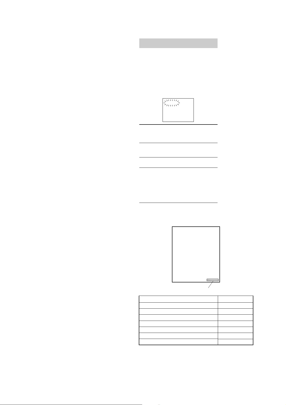
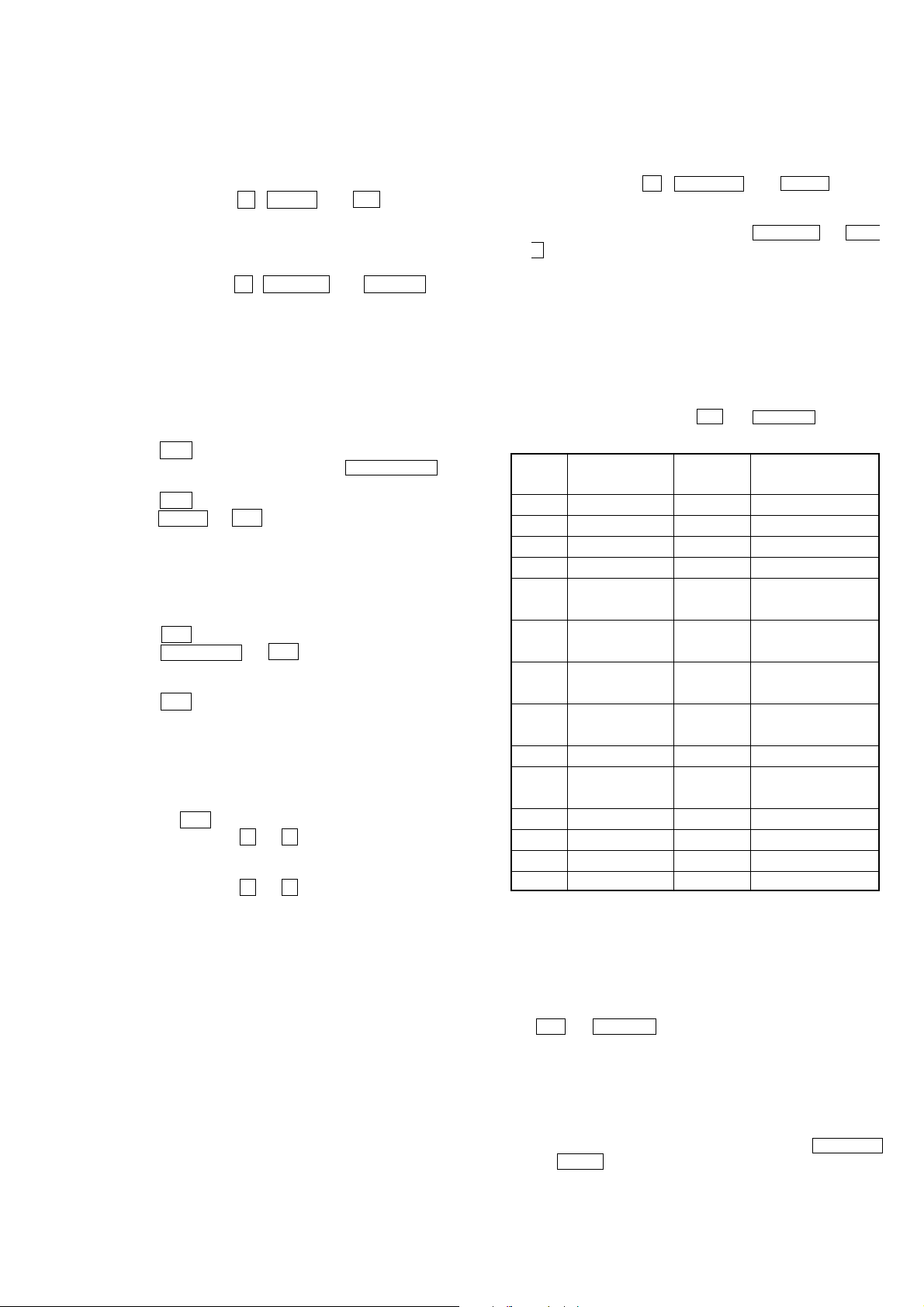
Self-diagnosis function
(When letters/numbers appear in the
display)
When the self-diagnosis function is activated to
prevent the system from malfunctioning, a fivecharacter service number (e.g., C 13 00) with a
combination of a letter and digits appears on
the screen. In this case, check the following
table.
C:13:00
First three
characters of
the service
number
Cause and/or
corrective
action
C 13 The disc is dirty.
, Clean the disc with a soft cloth
(see page 70).
C 31
The disc is not inserted correctly.
, Re-insert the disc correctly.
To prevent a malfunction, the
system has performed the selfdiagnosis function.
, Contact your nearest Sony
dealer or local authorized Sony
service facility and give the
5-character service number.
Example: E 61 10
E XX
(XX is a number)
Ver 1.5
AM tuner section
Tuning range
Pan-American models: 530 – 1,710 kHz
Philippine models: 531 – 1,602 kHz (with the
Other models: 531 – 1,602 kHz (with the
Antenna AM loop antenna
Antenna terminals External antenna terminal
Intermediate frequency 450 kHz
General
Power requirements
Mexican model: 120 V AC, 60 Hz
Saudi Arabian model: 120 – 127 V, 220 V or
Thai model: 220 V AC, 50/60 Hz
Other models: 120 V, 220 V or
Power consumption 230 watts
Dimensions (w/h/d) Approx. 280 × 325 ×
Mass Approx. 10.6 kg
Design and specifications are subject to change
without notice.
(with the interval set at
10 kHz)
531 – 1,710 kHz
(with the interval set at
9 kHz)
interval set at 9 kHz)
interval set at 9 kHz)
530 – 1,710 kHz (with the
interval set at 10 kHz)
230 – 240 V AC,
50/60 Hz
Adjustable with voltage
selector
230 – 240 V AC,
50/60 Hz
Adjustable with voltage
selector
0.4 watts (in Power
Saving Mode)
368 mm
MODEL IDENTIFICATION
— BACK P ANEL —
NOTES ON MB BOARD EXCHANGE
If a MB board is exchanged, “DRIVE AUTO ADJUSTMENT” may
be unable to be performed. In this case, initialize a memory in the
following procedure.
1. Starting Test Mode (see page 2 (SUPPLEMENT-1)).
2. Press the 2 button of remote commander to set the Drive
Manual Operation (see page 4 (SUPPLEMENT-1)).
3. Press the 6 button of remote commander to set the Memory
Check (see page 6 (SUPPLEMENT-1)).
4. Press the [CLEAR] button of remote commander to initialize
a memory.
2
MODEL
600D : MY, SP model
600D : E3
600D : EA3
600D : TH
600D : E51
600D : MX
600DJ : EA3
•Abbreviation
E3 : 240V AC Area in E model
E51 : Chilean and Peruvian model
EA3 : Saudi Arabia model
MX : Mexican model
MY : Malaysia model
SP : Singapore model
TH : Thai model
Parts No.
PARTS No.
4-240-159-0s
4-240-159-1s
4-240-159-2s
4-240-159-4s
4-240-159-5s
4-240-159-6s
4-240-159-7s

NOTES ON HANDLING THE OPTICAL PICK-UP
BLOCK OR BASE UNIT
The laser diode in the optical pick-up block may suffer electrostatic
break-down because of the potential difference generated by the
charged electrostatic load, etc. on clothing and the human body.
During repair, pay attention to electrostatic break-down and also
use the procedure in the printed matter which is included in the
repair parts.
The flexible board is easily damaged and should be handled with
care.
NOTES ON LASER DIODE EMISSION CHECK
The laser beam on this model is concentrated so as to be focused on
the disc reflective surface by the objective lens in the optical pickup block. Therefore, when checking the laser diode emission,
observe from more than 30 cm away from the objective lens.
Laser component in this product is capable
of emitting radiation exceeding the limit for
Class 1.
HCD-RV600D/RV600DJ
TABLE OF CONTENTS
1. GENERAL ·········································································· 4
2. DISASSEMBLY································································ 6
2-1. Case (Top) ····································································· 7
2-2. Lid (DVD)····································································· 7
2-3. Front Panel Section ······················································· 8
2-4. DVD Mechanism Deck (CDM58D-DVBU17)············· 8
2-5. Tape Mechanical Deck (CWM43RR-01) ····················· 9
2-6. PANEL Board, SUB PANEL Board,
REMOTE Board ························································· 10
2-7. Cassette Holder ···························································11
2-8. SUB TRANSFORMER Board,
Back Panel, DC Fan (M961)······································· 11
2-9. TRANSFORMER Board, MAIN Board····················· 12
2-10. FRONT AMP Board, SURROUND Board,
REG Board·································································· 12
2-11. VIDEO Board, MB Board ·········································· 13
2-12. RF Board, DRIVER Board ········································· 13
2-13. Optical Pick-up ··························································· 14
2-14. MOTOR Board, DIODE Board, SENSOR Board ······ 14
3. TEST MODE ···································································· 15
4. MECHANICAL ADJUSTMENTS ····························· 18
5. ELECTRICAL ADJUSTMENTS ······························· 19
This appliance is classified as a CLASS 1 LASER product. The
CLASS 1 LASER PRODUCT MARKING is located on the rear
exterior.
CAUTION
Use of controls or adjustments or performance of procedures
other than those specified herein may result in hazardous radiation
exposure.
Notes on chip component replacement
•Never reuse a disconnected chip component.
• Notice that the minus side of a tantalum capacitor may be
damaged by heat.
Flexible Circuit Board Repairing
•Keep the temperature of soldering iron around 270˚C
during repairing.
• Do not touch the soldering iron on the same conductor of the
circuit board (within 3 times).
• Be careful not to apply force on the conductor when soldering
or unsoldering.
6. DIAGRAMS······································································ 21
6-1. Block Diagrams – DVD DSP Section – ···················· 21
– DVD SYS Section – ···················· 22
– Tuner Section –···························· 23
– Main Section –····························· 24
6-2. Circuit Boards Location ·············································· 25
6-3. Printed Wiring Board – RF Board – ··························· 26
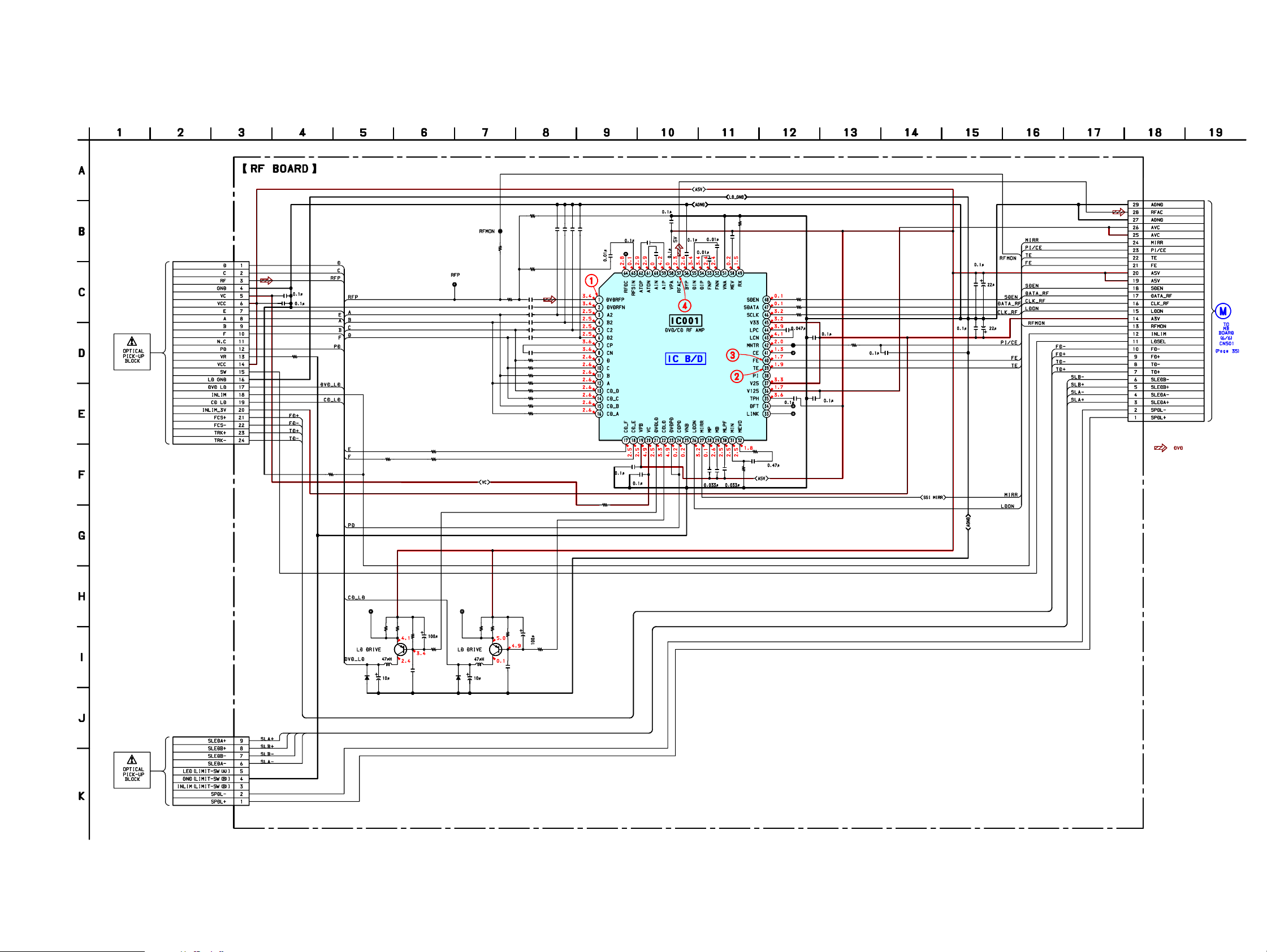
6-4. Schematic Diagram – RF Board – ······························ 27
6-5. Printed Wiring Board – MB Board (Side A) – ··········· 28
6-6. Printed Wiring Board – MB Board (Side B) – ··········· 29
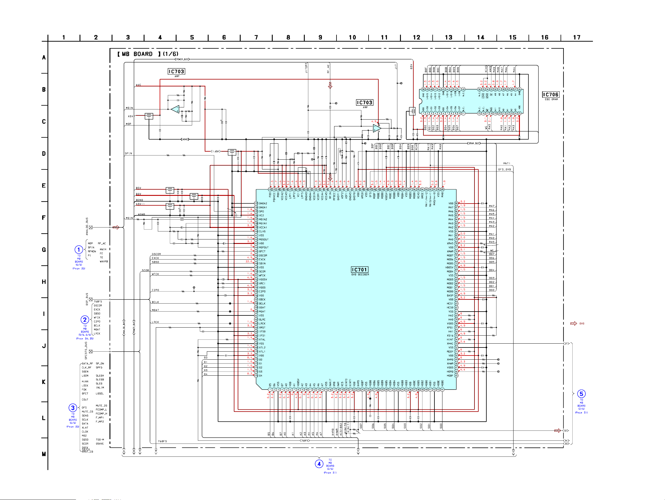
6-7. Schematic Diagram – MB Board (1/6) – ···················· 30
6-8. Schematic Diagram – MB Board (2/6) – ···················· 31
6-9. Schematic Diagram – MB Board (3/6) – ···················· 32
6-10. Schematic Diagram – MB Board (4/6) – ···················· 33
6-11. Schematic Diagram – MB Board (5/6) – ···················· 34
6-12. Schematic Diagram – MB Board (6/6) – ···················· 35
6-13. Printed Wiring Board – TC Board – ··························· 36
6-14. Schematic Diagram – TC Board – ······························ 37
6-15. Printed Wiring Board – Main Section – ····················· 38
6-16. Schematic Diagram – Main Section (1/3) – ··············· 39
6-17. Schematic Diagram – Main Section (2/3) – ··············· 40
6-18. Schematic Diagram – Main Section (3/3) – ··············· 41
6-19. Printed Wiring Board – VIDEO Board – ···················· 42
6-20. Schematic Diagram – VIDEO Board –······················· 43
6-21. Printed Wiring Board – FRONT AMP Board – ·········· 44
6-22. Schematic Diagram – FRONT AMP Board – ············ 45
6-23. Printed Wiring Board – Panel Section – ····················· 46
6-24. Schematic Diagram – Panel Section (1/2) – ··············· 47
6-25. Schematic Diagram – Panel Section (2/2) – ··············· 48
6-26. Schematic Diagram – Sensor Section – ······················ 49
6-27. Printed Wiring Board – Sensor Section – ··················· 49
6-28. Printed Wiring Board – TRANSFORMER Board –··· 50
6-29. Schematic Diagram – TRANSFORMER Board – ····· 51
6-30. Printed Wiring Board
– SUB TRANSFORMER Board – ····························· 52
6-31. Schematic Diagram
– SUB TRANSFORMER Board – ····························· 53
6-32. IC Pin Function Descriptions ······································ 54
SAFETY-RELATED COMPONENT WARNING!!
COMPONENTS IDENTIFIED BY MARK 0 OR DOTTED LINE WITH
MARK 0 ON THE SCHEMATIC DIAGRAMS AND IN THE PARTS
LIST ARE CRITICAL TO SAFE OPERATION. REPLACE THESE
COMPONENTS WITH SONY PARTS WHOSE PART NUMBERS
APPEAR AS SHOWN IN THIS MANUAL OR IN SUPPLEMENTS
PUBLISHED BY SONY .
7. EXPLODED VIEWS ······················································ 65
7-1. Main Section ·······························································65
7-2. Front Panel Section ····················································· 66
7-3. Chassis Section ··························································· 67
7-4. DVD Mechanism Deck Section
(CDM58D-DVBU17) ················································· 68
8. ELECTRICAL PARTS LIST ······································· 69
3
HCD-RV600D/RV600DJ
Ver 1.1 2002.11
Note for Service:
[DISC TRAY LOCK]
The disc tray lock function for the antitheft of a demonstration disc
in the store is equipped.
Setting Procedure :
1. Press the ?/1 button to turn the set on.
2. Press two buttons of x and Z simultaneously for five seconds.
3. The message “LOCKED” is displayed and the tray is locked.
SECTION 1
GENERAL
Main unit
ALPHABETICAL ORDER
A – J
ALBUM+/– ws (19, 20, 26)
AUDIO jacks wl (61)
CD SYNC ql (48, 50)
Deck A wg (47 )
Deck B qk (47, 48, 49, 50, 58)
DIRECTION 8 (47, 48, 50, 58)
DISC 1 – 3 qs (18, 19, 20)
DISC SKIP/EX-CHANGE qd (17,
19, 22)
Disc tray qa (17)
DISPLAY 8 (45, 53, 54, 55)
DVD eg (18, 20, 26, 27, 36, 48,
49)
DVD DISPLAY q; (18, 23, 24,
34, 36, 37, 38, 41, 55)
DVD MENU 8 (26)
DVD TOP MENU 8 (26)
ECHO LEVEL control*
EFFECT ON/OFF 4 (51, 52)
ENTER qf (16, 18, 20, 23, 24, 26,
27, 34, 36, 37, 38, 43, 46, 49,
50, 52, 55, 57, 59)
FM MODE 8 (45)
GAME ea (56, 61)
GAME EQ wd (51)
GAME MIXING wf (56)
GROOVE 3 (51)
1
wk (58)
K – Z
KARAOKE PON*12 (57)
MD (VIDEO)*
MIC jack*
MIC LEVEL control*
MOVIE EQ 9 (51)
MUSIC EQ 6 (51)
P FILE wa (52)
PHONES jack qh
PLAY MODE 8 (18, 20, 49)
PTY*
REC PAUSE/START w; (48, 50,
REPEAT 8 (23)
SURROUND*
TAPE A/B ed (47, 48, 58)
TUNER MEMORY 8 (43)
TUNER/BAND ef (43, 44)
VIDEO jack e; (61)
VIDEO (MD)*
VOLUME control qg (33, 53, 59)
58)
4
8 (46)
3
wj (57)
12 34567 098qa
Releasing Procedure :
1. Press two buttons of x and Z simultaneously for five seconds.
2. The message “UNLOCKED” is displayed and the tray is
unlocked.
Note : When “LOCKED” is displayed, the tray lock is not released
by turning power on/off with the POWER button.
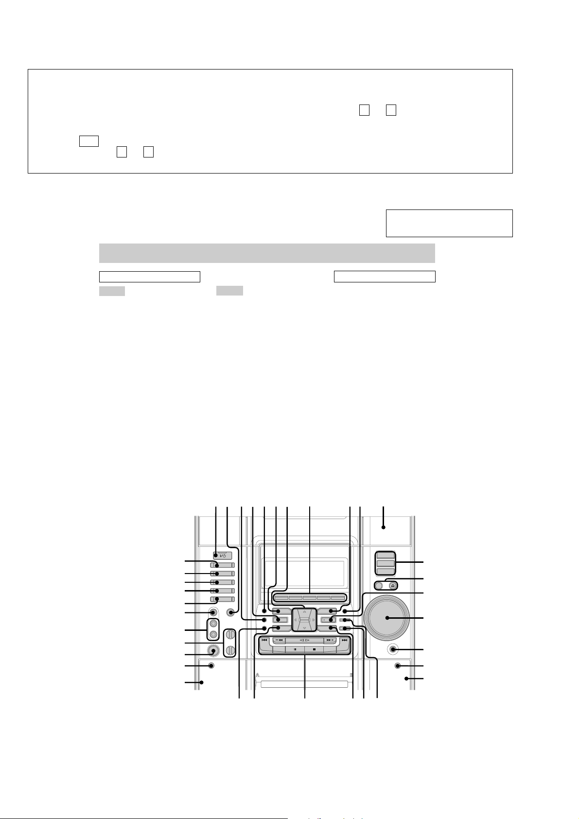
This section is extracted from
instruction manual.
BUTTON DESCRIPTIONS
?/1 (power) 1
v/V/b/B 7
2
es (62)
5
5 (53)
6
es (62)
3
wk (57)
Z OPEN/CLOSE qd
Z PUSH (deck B) qj
– m/M + ws
hH ws
./> ws
X ws
x ws
Z PUSH (deck A) wh
1
MHC-RV900D (except for
*
Latin American model) and
RV600D/RV600DJ (except
for Latin American model)
only
2
except for MHC-GX90D
*
3
*
MHC-RV900D and RV600D/
RV600DJ only
4
*
European model only
5
MHC-RV600D/RV600DJ only
*
6
*
MHC-GX90D only
eg
qs
ef
ed
es
qd
qf
ea
e;
qg
wl
wk
wj
wh
wg
wswdwf
qlw;wa
qh
qj
qk
4

HCD-RV600D/RV600DJ
Remote control
ALPHABETICAL ORDER
A – M
ALBUM +/– wd wl (19, 20, 26)
AMP MENU wa (57)
ANGLE w; (37)
AUDIO ed (35)
CLEAR qf (20, 22, 24, 25, 31)
CLOCK/TIMER SELECT 2
(51, 60)
CLOCK/TIMER SET 3 (16, 50,
59)
DISC +/– wg wj (19, 20, 22)
DISPLAY qa (45, 53, 54, 55)
DVD rs (18, 20, 21, 26, 27, 28,
36, 48, 49)
DVD DISPLAY qd (18, 23, 24,
34, 36, 37, 38, 41, 55)
DVD MENU ef (26)
DVD SETUP ek (28, 33, 40)
DVD TOP MENU ef (26)
EFFECT ON/OFF es (51, 52)
ENTER wk (16, 18, 20, 21, 23,
24, 26, 27, 28, 33, 34, 36, 37,
38, 40, 43, 46, 49, 50, 52, 55,
57, 59)
GAME 8 (56, 61)
GAME EQ e; (51)
GAME MIXING 0 (56)
GROOVE es (51)
MD (VIDEO) 9 (62)
MOVIE EQ e; (51)
MULTI ROOM* ea
MUSIC EQ e; (51)
12345
rf
rd
rs
ra
r;
el
ek
ej
eh
eg
ef
ed
es
ea
e;
wl
N – Z
NEXT eh (18, 27)
Number buttons qs (19, 27, 39,
40, 42, 49)
P FILE ws (52)
PLAY MODE r; (18, 20, 21, 49)
PRESET +/– eh (43, 44)
PREV eh (18, 27)
REPEAT el (23)
RETURN O ej (27, 39, 41)
SCAN/SLOW
SLEEP 1 (59)
SUBTITLE ql (38)
SURROUND es (53)
TAPE rd (47, 48)
TUNER/BAND ra (43, 44)
TUNING +/– eg (43, 45)
TV ?/1 4 (15)
TV CH +/– rf (15)
TV/VIDEO 7 (15)
TV VOL +/– 6 (15)
VOL +/– wf (33, 53, 59)
BUTTON DESCRIPTIONS
?/1 (power) 5
x qg
nN qh
X qj
M/m/</, wh
m eg
M eg
. eh
> eh
* This button does not function.
/ qk (19)
6
7
8
9
0
qa
qs
qd
qf
qg
qh
qj
qk
ql
w;
wa
ws
wd
Inserting two R6 (size AA)
batteries into the remote
e
E
E
e
Tip
With normal use, the batteries should last for about
six months. When the remote no longer operates the
system, replace both batteries with new ones.
Note
If you do not use the remote for a long period of time,
remove the batteries to avoid possible damage from
battery leakage.
Setting the clock
1
Press ?/1 to turn on the system.
2
Press CLOCK/TIMER SET on the
remote.
3
Press M or m on the remote repeatedly
to set the hour.
4
Press , on the remote.
The minute indication flashes.
5
Press M or m on the remote repeatedly
to set the minute.
6
Press ENTER.
The clock starts working.
To adjust the clock
1
Press CLOCK/TIMER SET on the remote.
2
Press M or m on the remote repeatedly to
select “CLOCK SET”, then press ENTER.
3
Do the same procedures as step 3 to 6
above.
Note
The clock settings are canceled when you disconnect
the power cord or if a power failure occurs.
wk
wj
wf
wg
wh
5
HCD-RV600D/RV600DJ
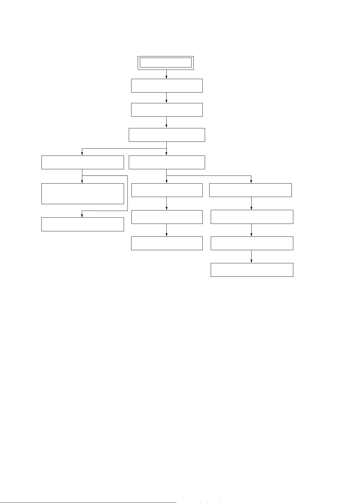
SECTION 2
DISASSEMBLY
• The equipment can be removed using the following procedure.
FRONT PANEL SECTION
SET
CASE (TOP)
DVD LID
TAPE MECHANISM DECK
(CWM43RR-01)
PANEL BOARD, SUB PANEL BOARD,
REMOTE BOARD,
MICROPHONE BOARD
CASSETTE HOLDER
DVD
MECHANISM DECK BLOCK
SUB TRANSFORMER BOARD,
BACK PANEL, DC FAN (M961)
TRANSFORMER
MAIN BOARD
FRONT AMP BOARD,
REG BOARD
BOARD,
Note : Follow the disassembly procedure in the numerical order given.
VIDEO BOARD, MB BOARD
RF BOARD, DRIVER BOARD
OPTICAL PICK-UP
MOTOR BOARD, DIODE BOARD,
TRAY, SENSOR BOARD
6
Note: Follow the disassembly procedure in the numerical order given.
)
4
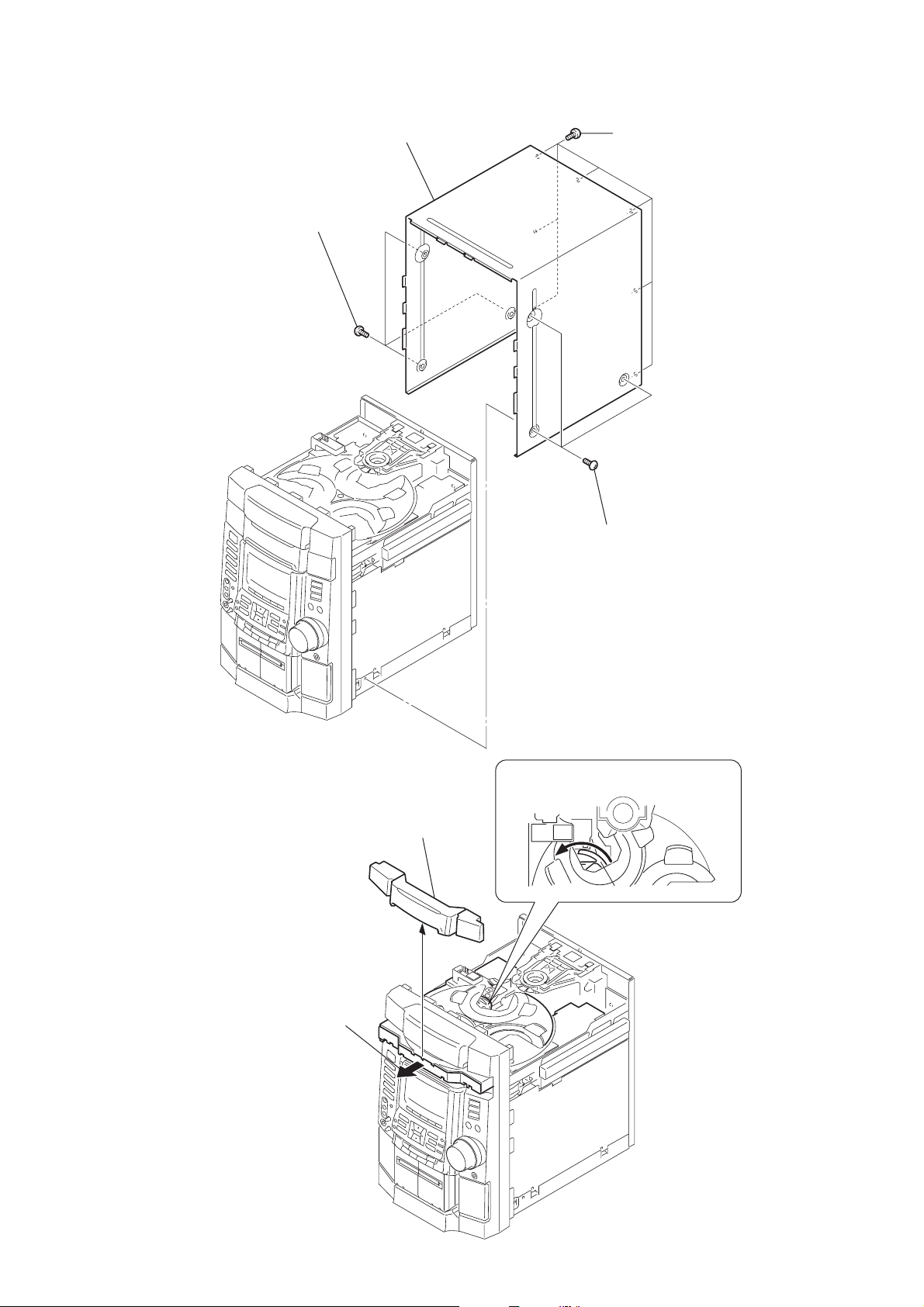
2-1. Case (Top)
2
three screws (case 3 TP2)
case
HCD-RV600D/RV600DJ
3
seven screws (BVTP 3
×
8
2-2. Lid (DVD)
4
lid (DVD)
3
1
three screws (case 3 TP2)
DVD mechanism deck (CDM58D-DVBU17)
1
Turn the pulley to the direction of arrow.
pulley
2
Pull-out the disc tray.
7

HCD-RV600D/RV600DJ
2-3. Front Panel Section
8
4
screw (BVTP 3
×
8)
front panel section
1
connector (CN502)
3
screw
(BVTP 3
×
8)
chassis section
5
three screws (BVTP 3
×
8)
2-4. DVD Mechanism Deck (CDM58D-DVBU17)
4
connector (CN103)
0
DVD mechanism deck (CDM58D)
2
flat type wire (CN104)
6
connector (CN602)
2
flat type wire (CN605)
5
connector (CN505)
6
7
7
connector (CN603)
connector (CN508)
three
screws (BVTP 3
×
8)
9
four
screws
(BVTP 3
×
8)
8
two
screws
1
connector (CN103)
3
connector
(CN709)
(BVTP 3
chassis section
×
8)
8
)
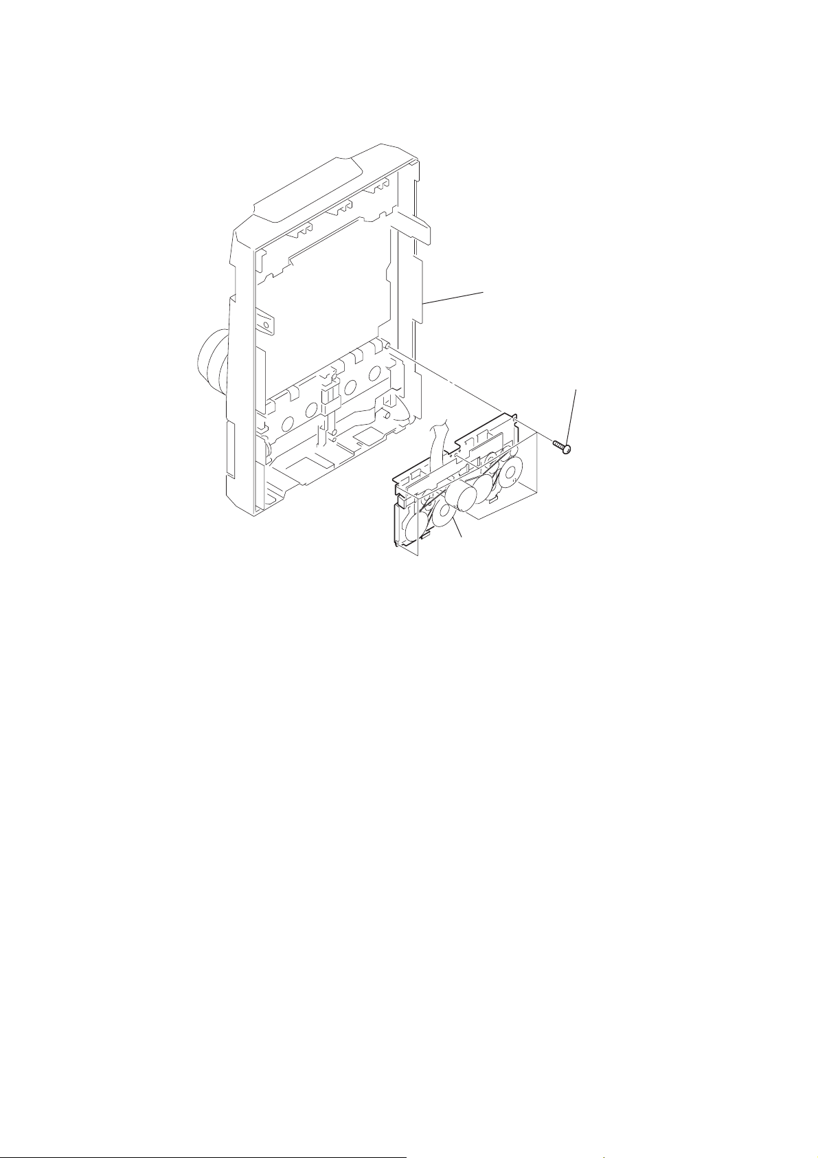
2-5. Tape Mechanical Deck (CWM43RR-01)
panel section
HCD-RV600D/RV600DJ
1
six
screws (BVTP 2.6
×
8
2
tape mechanism deck
(CWM43RR-01)
9

HCD-RV600D/RV600DJ
)
2-6. PANEL Board, SUB PANEL Board, REMOTE Board
2
One or two mic knobs
1
volume knob
0
two claws
front panel
qk
SUB PANEL board
9
two claws
qh
four screws
(BVTP 2.6
qd
×
8)
REMOTE board
qs
connector (CN1006)
7
five screws
(BVTP 2.6
6
Remove the
three solderings.
×
8)
3
connector
(CN1202)
10
qj
two screws
(BVTP 2.6
×
8)
qg
connector (CN1002)
qf
connector (CN1003)
8
six screws
(BVTP 2.6
qa
PANEL board
5
MICROPHONE board
×
8)
4
two screws
(BVTP 2.6
×
8

)
2-7. Cassette Holder
8
cassette, holder (R)
4
cassette, holder (L)
6
HCD-RV600D/RV600DJ
3
cassette door, spring (B)
2
1
5
7
cassette door, spring (A)
2-8. SUB TRANSFORMER Board, Back Panel, DC Fan (M961)
qf
back panel
1
connector (CN901)
2
connector (CN902)
qa
SUB TRANSFORMER board
3
connector (CN903)
0
three
(BVTP 3
screws
panel section
×
8)
7
(BVTP 3
two
screws
5
(BVTP 3
6
(BVTT 3
8
(BVTP 3
×
8)
qs
two
screws
(BVTP 3
five
screws
×
screw
×
screw
×
×
8)
6)
8
8)
chassis section
qd
dc fun (M961)
4
connector (CN704)
9
four
screws
(BVTT 3
×
6)
11

HCD-RV600D/RV600DJ
)
)
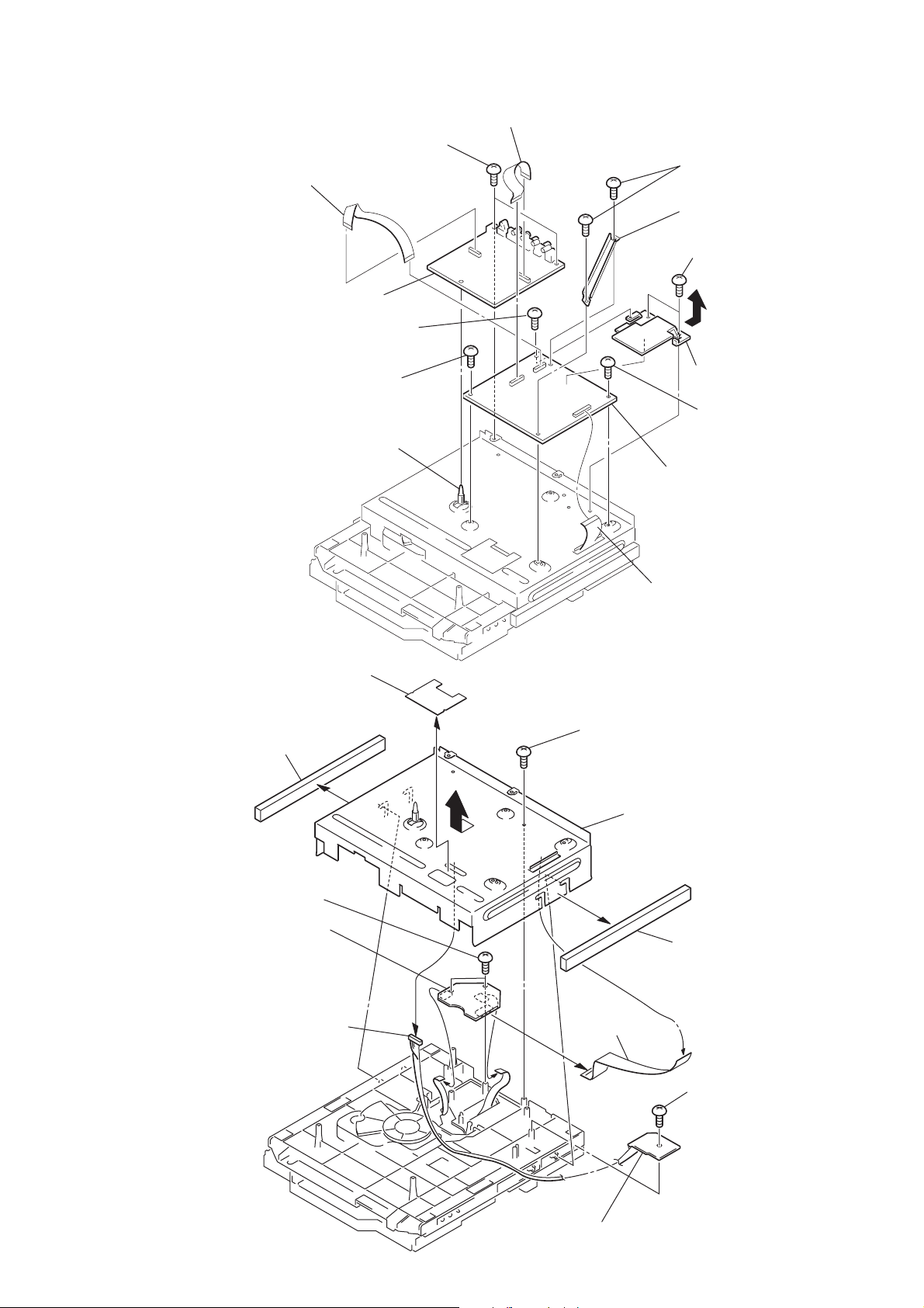
2-9. TRANSFORMER Board, MAIN Board
9
(BVTP 3
6)
two
5
TRANSFORMER board
3
two
(BV 4
2
connector
(CN915)
1
connector
(CN914)
8
(BVTT 3
4
two
(BV 4
screws
×
8)
two
screws
screws
×
×
8)
screws
×
0
qa
two claws
cover (heat sink)
qh
FRONT AMP board ASSY
7
three
(BVTT 3
screws
qf
×
6)
TC board
qs
connector (CN609)
qd
connector (CN608
8)
2-10.FRONT AMP Board, SURROUND Board, REG Board
heat sink assy
2
bracket (PWB)
1
two
screws
(BVTP 3
×
8)
4
bracket (PWB)
3
(BVTP 3
two
screws
×
qa
lead pin board
8)
qg
MAIN board
0
five
screws
(BVTP 3
×
8)
6
two
screws
(BVTP 3
×
8)
12
6
REG board
5
s
crew
(BVTP 3
×
8)
9
FRONT AMP board
7
five
screws
(BVTP 3
×
8
two
screws
(BVTP 3
8)
×
16
)
)
)
2-11. VIDEO Board, MB Board
1
flat type wire (CN501,CN202)
3
two
screws
(BVTP 3
×
2
flat type wire
(CN503,CN302)
8)
HCD-RV600D/RV600DJ
Ver 1.1 2002.11
7
two
screws
×
screws
×
8)
8)
(BVTP 3
8
bracket (AL)
0
two
(BVTP 3
5
VIDEO board
4
2-12. RF Board, DRIVER Board
7
cushion (DVD)
9
screw
(BVTT 3
qd
screw
(BVTP 3
PWB holder
2
cushion (A)
×
qa
×
6)
qs
8)
6
1
screw
(BVTP 3
×
8)
heat sink (DVD
qf
screw
×
(BVTP 3
qg
MB board
flat type wire (CN501
8)
two
screws (PTP 2.6
qa
qs
RF board
5
×
12)
connector
0
3
9
4
flat type wire
qf
DRIVER board
8
bracket (DVD)
6
cushion (DVD)
qd
screw (BVTP 2.6
×
8
13

HCD-RV600D/RV600DJ
)
2-13.Optical Pick-up
3
step
6
insulator
screw (L)
2
2-14.MOTOR Board, DIODE Board, SENSOR Board
qa
qs
tray (DVD)
screw (PTPWH 2.6
5
connector (CN723)
×
4
step
screw (L)
7
insulator
9
optical pick-up
5
step
screw (L)
8
insulator
1
floating
screw (PTPWH M2.6
0
holder (DBU1) assy
8)
6
MOTOR board
1
two
screws (BVTP 2.6
×
8)
14
9
screw (BVTP 2.6
×
8)
8
DIODE board
0
qd
screw (BVTP 2.6
7
screw (BVTP 2.6
bracket (sensor)
×
×
3
flat type wire (CN721)
2
8)
8)
Remove the two solderings of motor.
4
connector (CN722)
qf
SENSOR board
SECTION 3
TEST MODE
HCD-RV600D/RV600DJ
Ver 1.1 2002.11
[Cold Reset]
• The cold reset clears all data including preset data stored in the
RAM to initial conditions. Execute this mode when returning
the set to the customer.
Procedure:
1. Press three buttons x , ENTER , and ?/1 simultaneously.
2. The fluorescent indicator tube display “COLD RESET” and
the set is reset.
[Hot Reset]
1. Press three buttons x , GAME EQ , and DISPLAY simulta-
neously.
2. The fluorescent indicator tube becomes blank instantaneously,
and the set is reset
[Tuner Step Change] (Except for European and Middle Eastern
models)
•A step of AM channels can be changed over between 9 kHz and
10 kHz.
Procedure:
1. Press `/1 button to turn the set ON.
2. Select the function “TUNER”, and press TUNER/BAND button
to select the BAND “AM”.
3. Press `/1 button to turn the set OFF.
4. Press ENTER and `/1 buttons simultaneously, and the display
of fluorescent indicator tube changes to “AM 9 k STEP” or
“AM 10 k STEP”, and thus the channel step is changed over.
[VIDEO/MD Function Change]
• Change of function VIDEO or MD ( also the input level changes).
Procedure:
1. Press `/1 button to turn the set ON.
2. Press VIDEO (MD) and `/1 buttons simultaneously, and the
display of fluorescent indicator tube changes to “MD” or
“VIDEO”, and thus the channel step is changed over.
3. Press `/1 button to turn the set OFF.
[DISC TRAY LOCK]
The disc tray lock function for the antitheft of a demonstration disc
in the store is equipped.
Setting Procedure :
1. Press the ?/1 button to turn the set on.
2. Press two buttons of x and Z simultaneously for five seconds.
3. The message “LOCKED” is displayed and the tray is locked.
Releasing Procedure :
1. Press two buttons of x and Z simultaneously for five seconds.
2. The message “UNLOCKED” is displayed and the tray is
unlocked.
Note : When “LOCKED” is displayed, the tray lock is not released
by turning power on/off with the POWER button.
[GC Test Mode]
•This mode is used to check the FL tube, LED, keyboard, volume and phones.
Procedure:
1. Press three buttons x , GAME EQ , and DISC 2 simulta-
neously.
2. LEDs and fluorescent indicator tube are all turned on.
3. Press simultaneously the two buttons of GAME EQ and DISC
2 . Whenever these two buttons are pressed simultaneously, the
mode changes from Key check, Key count check, Headphones
input check and Volume check in this order.
4. When the Key check mode is entered, the display shows the
indication of “KEY 0 0 0”.
The keys that are assigned to the respective channels of the key
entry signal lines (KEY0, KEY1, KEY2) that are input to IC001
Display Controller on the panel board, are checked. While you
press the button, the number that corresponds to the key shown
in the table below, is displayed in the location of the
corresponding channel. (The ?/1 and DISPLAY buttons are
not included in these channels.)
Display
1DVD X DISC 1
2 TUNER/BAND x DISC 2
3TAPE A/B ALBUM + DISC 3
4 VIDEO (MD) >Z OPEN/CLOSE
5 GAME M +
6— g G
7DVD MENU – m
8 GAME EQ ALBUM –
9 MUSIC EQ . CD SYNC
10
11 GAME MIXING V P FILE
12 GROOVE B ENTER
13 — v MOVIE EQ
14 — — DVD DISPLAY
5. When the Key count check mode is entered, the display shows
the indication of “KEY 0 1”.
Whenever the button is pressed, number in the first digit
increments. (RV90D: 38) At the same time, only when the key
is being pressed, the KEY channel is displayed in the second
digit. (KEY0: 1, KEY1: 2, KEY2: 3)
(The buttons that are already pressed once and the buttons of
?/1 and DISPLAY are not counted.)
6. When the Headphones input check mode is entered, the display
shows the indication of “H_P OFF” or “H_P ON” depending
on the PHONES jack status.
7. When the Volume check mode is entered, the display shows the
indication of “VOLUME FLAT” or “VOLUME DOWN” or
“VOLUME UP” depending on the VOLUME status.
8. You can exit the Test Mode when you press the GAME EQ
and DISC 2 buttons simultaneously.
Left Center Right
(KEY0) (KEY1) (KEY2)
EX-CHANGE
TUNER MEMORY
PLAY MODE
DVD TOP MENU
EFFECT ON/OFF
b
PAUSE/START
DISC SKIP/
FM MODE
REPEAT
DIRECTION
REC
15

HCD-RV600D/RV600DJ
[MC Test Mode]
•This mode is used to check operations of the respective sections
of Amplifier, Tuner, and Tape.
Procedure:
•To enter MC Test Mode
1. Press `/1 button to turn on the set.
2. Press the three buttons of x , GAME EQ and DISC 3 simul-
taneously.
* Check of Amplifier
Initial settings: Input , GAME
EQ , FLAT
Mode , MUSIC
VA C S , OFF
Output channel switching:
MUSIC key: L , LR , R through
MOVIE key: L , SL R , SR through
GAME key:L , L, SL, C R , R, SR, SW through
TOOL MODE key: L , CR , SW through
1. When VOLUME control knob is turned clockwise even
slightly, the sound volume increases to is maximum and a
message “VOLUME MAX” appears for two seconds, then the
display returns to the original display.
2. When VOLUME control knob is tuned counter-clockwise
even slightly, the sound volume decreases to its minimum and a
message “VOLUME MIN” appears for two seconds, then the
display returns to the original display.
3. When you press the v button, the message “GEQ MAX” is
displayed and the entire band of the graphic equalizer is set to
the maximum level.
4. When you press the V button, the message “GEQ MIN” is
displayed and the entire band of the graphic equalizer is set to
the minimum level.
5. When you press the b , B or P FILE button, the message
“GEQ FLT” is displayed and the entire band of the graphic
equalizer is set to the center level.
6. Whenever you press the ENTER button, it toggles between
“VACS ON” and “VAC OFF” so that you can switch ON or
OFF of VACS.
*To return to normal mode again.
1. When you want to exit this mode, press `/1 button.
2. The cold reset is enforced at the same time.
[Aging Mode]
This mode can for operation check of tape deck section.
• If an error occurred:
The aging operation stops and display then status.
• If no error occurs:
The aging operation continues repeatedly.
Procedure:
1. Press the DVD button to select the function “DVD”.
2. Load the tapes into the decks A and B respectively.
3. Set a disk in “DISK1” tray.
4. Press the PLAY MODE button to set the “ALL DISCS” mode,
and press the REPEAT button to “REPEAT” off.
5. Press three buttons of x , GAME EQ , and DISC SKIP/EX-
CHANGE simultaneously.
6. The florescent indicator tube display “AGING”, aging mode
start.
7. To exit from the aging mode, operate the cold reset.
•The sequence during the aging mode is following as below.
• If an error occurred, stop display that step.
Aging mode sequence (Tape deck section):
Rewind the tape A
“TAPE A AG-1”
Shut off
Rewind the tape B
“TAPE A AG-2”
Shut off
FWD play the tape A
“TAPE A AG-3”
2 minutes
Fast forward the tape A
“TAPE A AG-4”
Shut off or 20 seconds
RVS play the tape A
“TAPE A AG-5”
2 minutes
Rewind the tape A
“TAPE A AG-6”
Shut off
16
FWD play the tape B
“TAPE B AG-3”
2 minutes
Fast forward the tape B
“TAPE B AG-4”
Shut off or 20 seconds
RVS play the tape B
“TAPE B AG-5”
2 minutes
Rewind the tape B
“TAPE B AG-6”
Shut off

HCD-RV600D/RV600DJ
Ver 1.3 2003.10
[DVD Service Mode]
•The sequence during the aging mode is following as below.
Aging mode sequence (DVD section):
Tray Turn
Disc 1 Chucking
TOC Read
Track 1 Play
2 seconds
Last Track Play
2 seconds
[DVD and CD Ship Mode (No Memory Clear)]
•This mode moves the position to the position durable to vibration Use this mode when returning the set to the customer after
repair.
Procedure:
1. Press `/1 button to turn the set ON.
2. Press three DVD button and
3. After the “STANBY” display blinks six times, a message
“LOCK” is displayed on the fluorescent indicator rube, and the
DVD ship mode is set.
[DVD and CD Ship Mode (Memory Clear)]
•This mode moves the pick-up to the position durable to vibration. Use this mode when returning the set to the customer after
repair.
Procedure:
1. Press
2. Press three buttons ENTER , DISC 1 , and DVD button
simultaneously.
3. After the “STANDBY” display blinks six times, a message
“LOCK” is displayed on the fluorescent indicator tube, and the
DVD ship mode is set.
button to turn the set ON.
`/1
button simultaneously.
`/1
17
HCD-RV600D/RV600DJ
SECTION 4
MECHANICAL ADJUSTMENTS
[REPEAT 5 LIMIT OFF MODE]
•This mode is used to enable infinite repetitions.
Normally, the number of repetitions allowed is 5.
Procedure:
1. Press
2. Set the function “DVD”.
3. Press three burtons x , MUSIC EQ and DISC 2 is simulta-
neously.
4. Infinite repetitions is enabled.
5. This state is maintained ( memorized ) until COLD RESET is
executed.
button to turn ON the power supply.
`/1
Precaution
1. Clean the following parts with a denatured alcohol-moistened
swab:
record/playback heads pinch rollers
erase head rubber belts
capstan idlers
2. Demagnetize the record/playback head with a head
demagnetizer.
3. Do not use a magnetized screwdriver for the adjustments.
4. After the adjustments, apply suitable locking compound to the
parts adjusted.
5. The adjustments should be performed with the rated power
supply voltage unless otherwise noted.
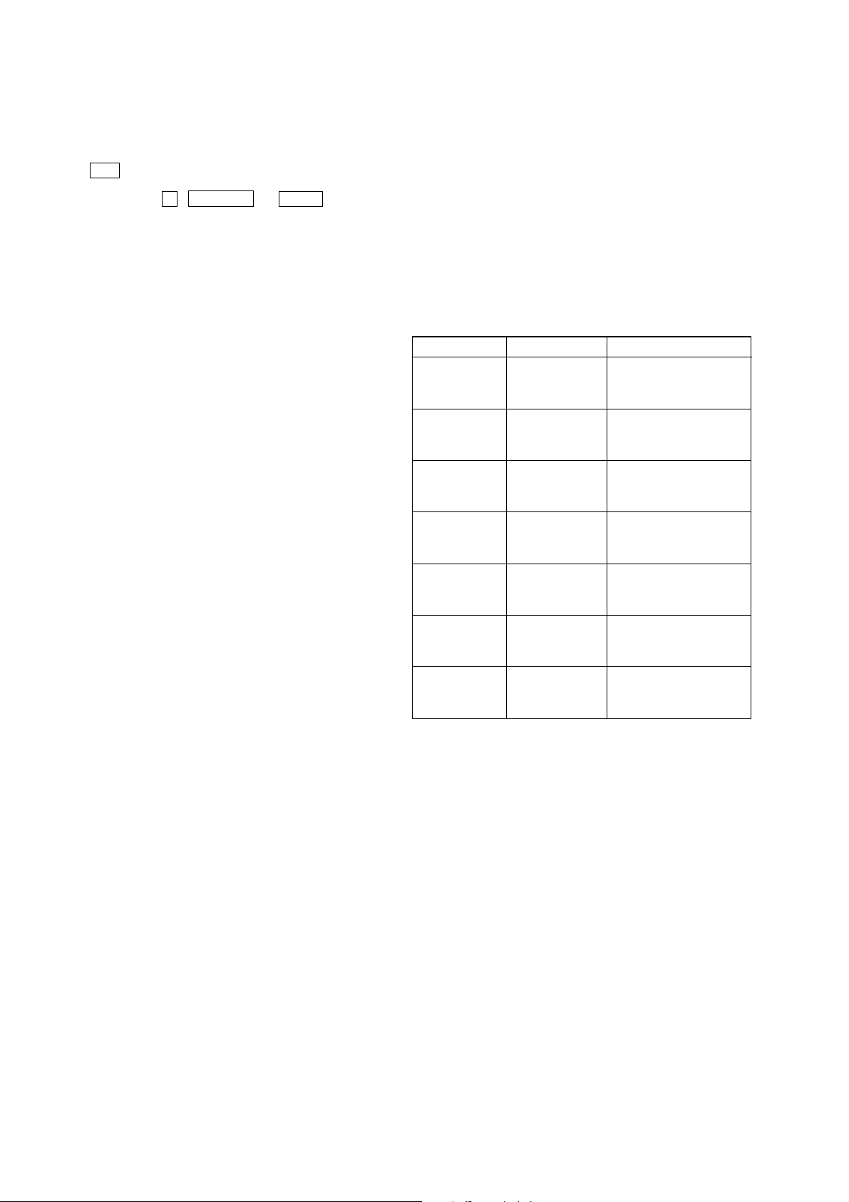
Torque Measurement
Mode
FWD
FWD
back tension
REV
REV
back tension
FF/REW
FWD tension
REV tension
Torque meter
CQ-102C
CQ-102C
CQ-102RC
CQ-102RC
CQ-201B
CQ-403A
CQ-403R
Meter reading
3.06 N • m to 6.96 N • m
31 to 71 g • cm
(0.43 – 0.98 oz • inch)
0.19 N • m to 0.58 N • m
2 to 6 g • cm
(0.02 – 0.08 oz • inch)
3.06 N • m to 6.96 N • m
31 to 71 g • cm
(0.43 – 0.98 oz • inch)
0.19 N • m to 0.58 N • m
2 to 6 g • cm
(0.02 – 0.08 oz • inch)
6.96 N • m to 14.02 N • m
71 to 143 g • cm
(0.98 – 1.99 oz • inch)
9.80 N • m
100 g or more
(3.53 oz or more)
9.80 N • m
100 g or more
(3.53 oz or more)
18
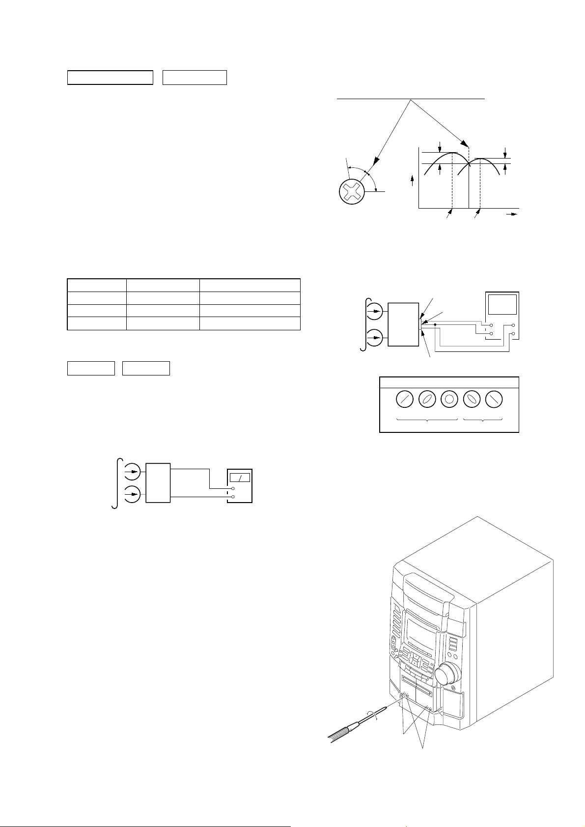
SECTION 5
r
MAIN
board
CN607
set
test tape
P-4-A100
(10 kHz, –10 dB)
pin
7
oscilloscope
L-CH
R-CH
V
H
waveform of oscilloscope
in phase 45°90°135°180
°
good
wrong
pin
6
pin
5
L
R
forward
reverse
ELECTRICAL ADJUSTMENTS
HCD-RV600D/RV600DJ
DECK SECTION
0 dB=0.775 V
1. Demagnetize the record/playback head with a head
demagnetizer.
2. Do not use a magnetized screwdriver for the adjustments.
3. After the adjustments, apply suitable locking compound to the
parts adjust.
4. The adjustments should be performed with the rated power
supply voltage unless otherwise noted.
5. The adjustments should be performed in the order given in this
service manual. (As a general rule, playback circuit adjustment
should be completed before performing recording circuit
adjustment.)
6. The adjustments should be performed for both L-CH and RCH.
7. Switches and controls should be set as follows unless otherwise
specified.
•Test Tape
Tape Signal Used for
P-4-A100 10 kHz, –10 dB Azimuth Adjustment
WS-48B 3 kHz, 0 dB Tape Speed Adjustment
P-4-L300 315 Hz, 0 dB Level Adjustment
Record/Playback Head Azimuth Adjustment
DECK A DECK B
2. Turn the adjustment screw and check output peaks. If the peaks
do not match for L-CH and R-CH, turn the adjustment screw
so that outputs match within 1dB of peak.
Output
level
within
1dB
L-CH
peak
R-CH
peak
within
1dB
Screw
position
L-CH
peak
Screw
position
R-CH
peak
3. Mode: Playback
Note: Perform this adjustments for both decks
Procedure:
1. Mode: Playback
test tape
P-4-A100
(10 kHz, –10 dB)
set
main board
CN607
Pin
5
(L-CH)
7
(R-CH)
Pin
main board
CN607
6
(GND)
Pin
level mete
+
–
4. After the adjustments, apply suitable locking compound to the
pats adjusted.
Adjustment Location: Playback Head (Deck A).
Record/Playback/Erase Head (Deck B).
19
HCD-RV600D/RV600DJ
Ver 1.5
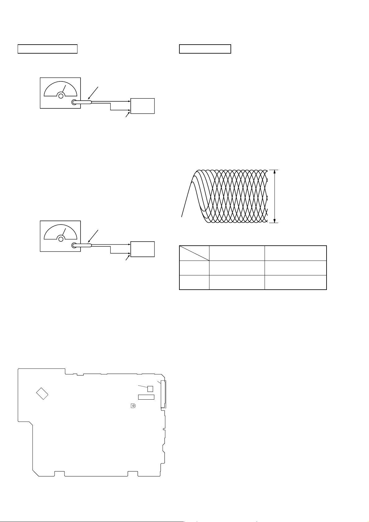
TUNER SECTION
FM Tuned Level Adjustment
FM RF SSG
Ω
coaxial
75
set
Carrier frequency : 98 MHz
Modulation : AUDIO 1 kHz, 75 kHz
deviation (100%)
Output level : 25 dB (at 75
Ω
open)
Procedure:
1. Supply a 25 dB 98 MHz signal from the ANTENNA terminal.
2. Tune the set to 98 MHz.
3. Adjust RV11 to the point (moment) when the TUNED indicator
will change from going off to going on.
Adjustment Location: MAIN board
Null Adjustment
FM RF SSG
75 Ω coaxial
FM ANTENNA terminal
(TM1)
DVD SECTION
AUTO SERVO ADJUSTMENT
After parts related to the servo circuit (RF amplifier (IC001), DSP
(IC509), motor driver (IC501), EEPROM (IC203) so on) are
replaced, re-adjusting the servo circuit is necessary. Select “ALL”
at “1. DRIVE AUTO ADJUSTMENT” (Refer to page 3
(SUPPLEMENT-1) in TEST MODE) and adjust DVD-SL (single
layer), CD and DVD-DL (dual layer).
RFMON Level Check
Perform a RFMON level check before exchanging optical pick-up.
Measurement Point: MB board CN501
17 pin (RFMON) — 1 pin (AGND)
RFMON signal waveform
VOLT/DIV: 200 mV
TIME/DIV: 500 ns
RFMON level
set
Carrier frequency : 98 MHz
Modulation : AUDIO 1 kHz, 75 kHz
deviation (100%)
Output level : 60 dB (at 75 Ω open)
FM ANTENNA terminal
(TM1)
Procedure:
1. Supply a 60 dB 98 MHz signal from the ANTENN A terminal.
2. Tune the set to 98 MHz.
3. Measure voltage between pin 22 and pin 3 of IC 11. Adjust
T11 ubtil the voltage becomes 0 V.
Adjustment Location: MAIN board
Adjustment Location
[MAIN BOARD] Component side
IC1104
T11
NULL
IC11
TM1
112
24 13
RV11
FM TUNED LEVEL
• Standard value
DVD
CD
Test Disc
TDV-520CSO
(J-2501-236-A)
LUV-P01
(4-999-032-01)
RFMON level
Standard V alue
1.09 ± 0.2 Vp-p
1.05 ± 0.2 Vp-p
20
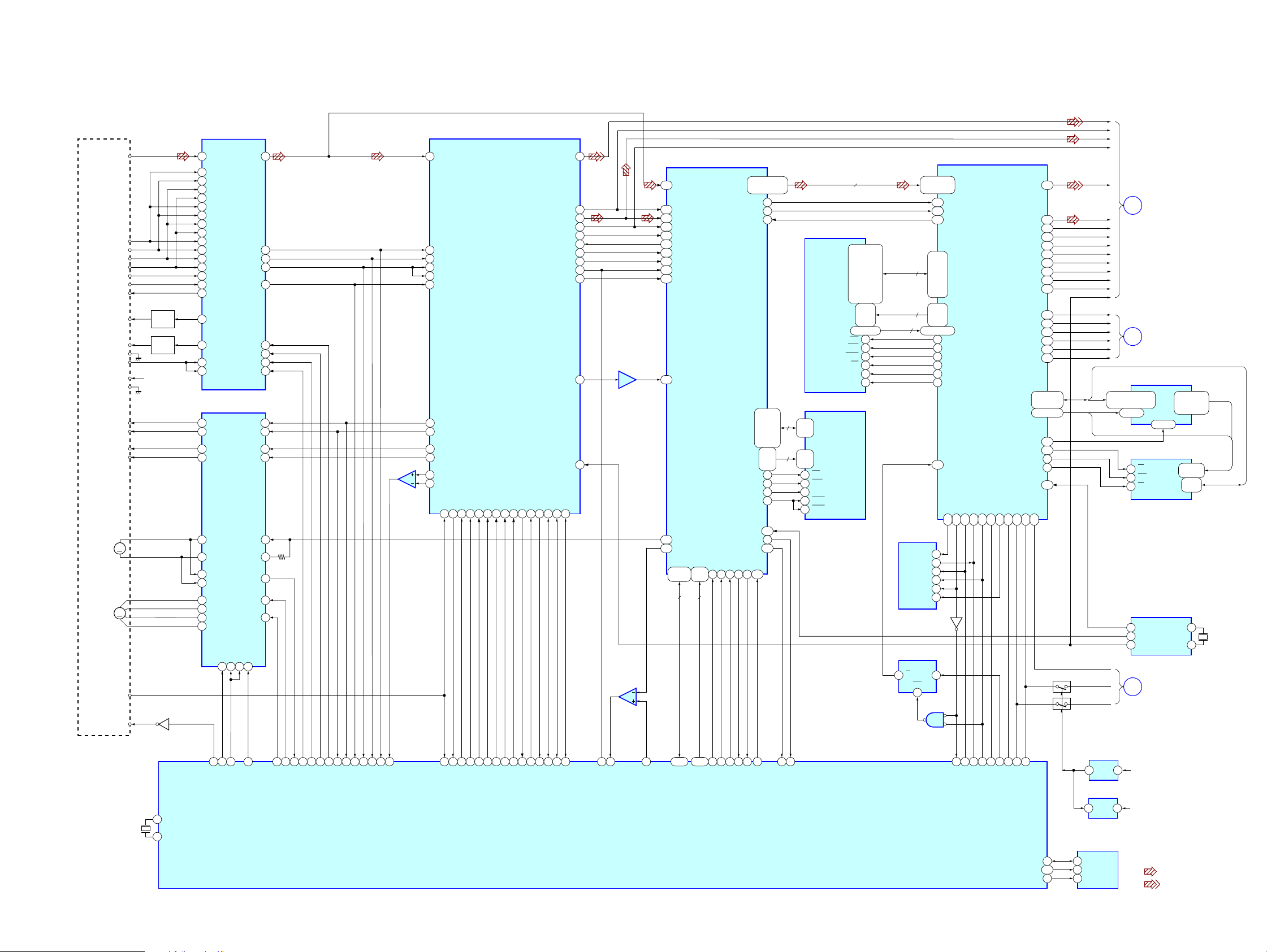
6-1. Block Diagrams – DVD DSP Section –
OPTICAL PICK-UP
BLOCK
(KHM-240AAA)
RF
A
B
C
D
E
F
VC
Q001
+5V
SPDL+
SPDL-
SLA+
SLA-
SLB+
SLB-
40 XTAL
41 EXTAL
LD
DRIVE
Q002
LD
DRIVE
Q901
SPINDLE
MOTOR
SLED
MOTOR
DVDLD
CDLD
LD GND
VCC
GND
FCS+
FCS-
TRK+
TRK-
M
M
INLIM
PD
SW
X901
20MHz
IC001
DVD/CD RF AMP
1
DVDRFP
A23
B2
4
C25
6
D2
A12
B
11
C10
9
D
CD A16
CD B
15
CD C
14
13
CD D
17
CD F
18
CD E
VC
20
21
DVD LD
22
CD LD
23
DVDPD
24
CDPD
IC501
MOTOR/COIL DRIVE
36
DO1+
37
DO1-
DO2+
34
DO2-
35
DO5+27
DO5-28
IN6+47
IN6-46
DO3+
32
31
DO3DO4+
30
29
DO4-
TSDM
76
73
63
TSDM
LDSEL
MUTE5
SPON
IN1+
IN1-
IN2+
IN2-
IN5-
OUT5
IN3-
IN4-
MUTE12
MUTE34
19202122
60
MUTE 2D
HCD-RV600D/RV600DJ
SECTION 6
Ver 1.2 2003.10
DIAGRAMS
SYS-RESET
D+3.3V
DOUT
LRCK
PCMD
IEC958
DATA0
BCK-ZIBA
LRCK-ZIBA
CDSEL
MREQ
768FS
WIDE
HAD0-15
HA1-3
I2C-CL
I2C-DA
3 1
1 3
IC903
EEPROM
5 SDA
SCL
6
WP
7
BCK
XCK
ML
MC
MDI
V
C
Y
CB/R
CR/B
49-47,45-40,38-36
IC907
REG
IC210
REG
A
B
55,54,52,51,
34,33,31
26 CE
11 WE
28 OE
CLOCK GENERATOR
3 27M
10
13
C
D+5V
+1.8V
MAIN
SECTION
(Page 24)
MAIN
SECTION
(Page 24)
IC215
ADDRESS LATCH
LE
29 56
IC205
RAM
A0-A7,
A9-A18,
A20,A21
DQ0-DQ15
IC906
33M
33M
DVD SYS
SECTION
(Page 22)
• Signal Path
: DVD
: DIGITAL OUT
2,3,5,6,8-10
12-17,19-21,
23,24,26
1-7,10,13,
16-25,48
29-36,
38-45
7XTI
8XTI
HA4-22
HA1-3
HA1-8,
HA10-19
HA21,22
HAD0-15
X902
27MHz
IC509
CD DECODER
SERVO DSP
64
SCLK
8
13
71
SCLK CD
GFS
COUT22FOK24LOCK
19
30
74
GFS CD
COUT CD
DOUT
PCMD
SBSO
SCOR
WDCK
XTAI
75
FOK CD
65LRCK
66
67BCK
79
80EXCK
10WFCK
14C2PO
15
17
25MDP
71
LOCK CD
26
64
SCOR
IC703(1/2)
AMP
IC703(2/2)
AMP
JIT
SPIN
45
SCK DSD
RFIN
117
LRCK
163
MDAT
160
BCLK
158
SBIN
148
EXCK
147
WFCK
151
C2PO
155
SCOR
150
GSCOR
146
MDIN2
137
SPO
135
APE0
107
D0-D7 A0-A7
172-176
1,2,4
8 8
14-21
D0-D7
57RFAC
MIRR
27MIRR
40FE
39TE
PI/CE
42MNTR
SDEN
48SDEN
DATA RF
47SDATA
CLK RF
46SCLK
LDON
26LDON
FFDR
48
FRDR
1
TFDR
3
TRDR
4
13
14
45OUT6
7
10
44
43
SLED B
SLED A
62
82
28
FG
LDON
2
83
SDATA RF
SDCLK RF
8
SDEN
FCS JMP 2
7
66
RI
FCS JMP 1
65TE67FE29
61
MIRR
SLED
50 RFAC
20 MIRR
39 FE
40 SE
41 TE
43 RFDC
33
FFDR
34 FRDR
31
TFDR
32
TRDR
5
29
7
IC503
AMP
SFDR
6
30
SRDR
26
31
SSTP
76
52
INLIM
SQSO77SQCK
54
SQCK
SQSO
MUTE
XRST
MD2
4
3
2
63
49 27 50 9 72
59
98
3
XDRST
MUTE CD
DOCTRL/ISBTEST
DATA5XLAT6CLOK7SENS
LAT CD
DATA CD
CLOK CD
SENS CD
IC701
DVD DECODER
HDB0-HDB8
5,7,
9-14
85
89-96
A0-A7
44,41,39,35
32,30,27,24,26
XDCK
XSRQ
MD0-MD15
MA0-MA9
XMWR
XRAS RAS
XOE OE
XCAS
XTL1
MNT1
GFS
XRD17XWR18XCS19XINT020XINT1
84
XRD
12
XWR
21
22
XCS DVD
INIT0 DVD23INIT1 DVD
164
25
46XSAK
48
53
66-69,71,
73-75,
96,97,99,
101,102,
104-106
79,80,
82-87,
89,91
76
95
171
92
109
XRST
XRST
FCOMP L
16
10
58
GFS DVD
6
41-49
21-24,
27-32
MNT1
2-10,
17
1878
3394
34
35
IC202
SDRAM
DQ0-DQ31
A0-A9,A10/AP,NC
IC706
SDRAM
I/O0-I/O15
A0-A9
WE
UCAS
LCAS
CONTROLLER
8
2,4,5,7,
8,10,11,13,
74,76,77,79,
80,82,83,85,
31,33,34,36,
37,39,40,42,
45,47,48,50,
51,53,54,56
25-27
60-66
24,21
16,71,28,59
WE
17
18 52
19 51
20 49
22 48
23 47
IC901
MECHANISM
177-174
171-168,182
32
12
4
62,73,86,97
IC203
EEPROM
WC
DO
IC904
FF
CKQ
3 1
CLR
6
4
SDEN
179
SDCLK
183
SDREQ
178
57-60
64-71
75-78
81-84
88-95
99-102
42-33
45,46
53
MWE
MCASCAS
MRASRAS
MCS0CS
BA0BS0
BA1BS1
188 DRVRDY
8
6
5DI
4SK
3CS
1R/B
Q201
IC902
GATE
2
1
IC206
DVD SYSTEM PROCESSOR
SDDATA0-SDDATA7,
SDERROR
MD0-MD31
MA0-MA11
MDQM0-MDQM3MDQM0-MDQM3
HAD0-HAD15
184 HIRQ1DRVIRQ
185 DRVCLKSCK ZIVA
186 DRVTXSO ZIVA
187 DRVRXSI ZIVA
157 CS EEPROM
158 WC EEPROM
36
35
34
33
32
CS ZIVA
37
HA1-HA3
191 RST SPCRST
116 HIRQ2
38
DRVRDY
VDAC 4
22,19-14,
2,207,206
XIN
161 I2C DAI2C SIO78160 I2C CLI2C SCL79202 RESET
SDA EEP
SCL EEP
WP EEP
11-3
Q903
Q904
156IEC958
150GPIO4(1)
149BCK
148LRCK
147XCK
109CDSEL
110MREQ
115ML
114MC
113MDI
131VDAC 0
128VDAC 1
125VDAC 2
122VDAC 3
119
107VS
190ALE
195HCS0
139
100
25WEH.UDS
27HEL.LDS
5
99
2121

HCD-RV600D/RV600DJ
– DVD SYS Section –
MAIN
SECTION
(Page 24)
S1002-1014
FUNCTION
KEY
S1022-1034
FUNCTION
KEY
S1042-1055
FUNCTION
KEY
S1081
ENCODER
VOLUME
F
HP
X1101
5MHz
IC1001
DISPLAY CONTROL
22 KEY0
KEY1
21
20 KEY2
13 VOL1A
14 VOL1B
3X1
4X2
17
HEADPHONE
ENTER
SEG1-33
26
27GAME-MIXING
28GAME-LED
29MD/VIDEO
30TAPE
31TUNER
32CD/DVD
16DECODE-LED
9S-OUT
8S-IN
7S-CLK
6RESET
33-58
61-67
68-80G1-13
Q1004-1008
Q1010-1012
LED
DRIVER
Q1001-1003
GRID
DRIVER
D1001-1005
D1007-1009
FL1001
FLUORESCENT
INDICATOR
TUBE
DVD DSP
SECTION
(Page 21)
IC1002
1110
56
34
IR
S1062
DISPLAY
S1061
POWER
REMOTE
CONTROL
RECIEVER
C
1312
98
12
IC1003
I2C-CL
I2C-DA
SYS-RESET
X800
32.768kHz
X801
16MHz
IC1104(3/3)
MASTER CONTROL
73 DISPLAY KEY
74 3POWER KEY POWER
CD/DVD POWER
4 SIRCS
29 IIC-CLK
30 IIC-DATA
41 SYS-RESET
S-IN
100
S-OUT
1
S-CLK
2
M-RESET
42
10 XC-IN
11 XC-OUT
13 X-OUT
15 X-IN
Q1009
LED
DRIVER
34
40SYS-POWER
40STB-RELAY
12RESET
18ACCUT
RESET
SWITCH
Q714
Q706
D1006
POWER
D+5V
(DVD)
+5V
+2.5V
DVD+12V
A+12V
GC+5V
IC704
REG
IC706
REG
IC702
REG
IC703
RESET
M+9V
D+4V
IC921
REG
12
4
AC3
AC4
IC901
REG
Q901
RELAY
DRIVE
F914
F915
F916
F917
F918
F919
VF
D902-905
13
IC922
REG
13
IC923
REG
13
IC934
REG
13
IC932
REG
13
Q723-725
SWITCH
13
Q715-716
SWITCH
13
IC705
REG
13
Q717
13
12
5
UNREG+20V
VP
UNREG+12V
+VH
-VH
+VL
-VL
Q971
REG
EVER+4V
D271
D371
D732
D911
D733
T911
POWER TRANSFORMER
T901
SUB TRANSFORMER
F911
F912
F913
RY901
S901
AC
IN
2222

– Tuner Section –
TM1
FM 75Ω
G
8
ANT IN
FE2
IF OUT
F OUT
VT
HCD-RV600D/RV600DJ
AM/FM IF MPX
Q1
CF1 CF2
+B
(FE2,3)
1
3
4
X51
4.5MHz
Q2
RF IF
AMP
10
1
22
A+12V
FM
XIN
XOUT
PLL
IC51
IF IN
AM OSC
FM
12
15
1
FM TUNED
LEVEL
A+12V
RV11
7
9VCO STOP
8IF REQ
11
24
12
10
IC11
FM IF
AM MIX OUT
AM/FM
OSC FM
VCO STOP
IF REQ MUTE
L OUT
R OUT
AM IF IN
13
14
AMP
Q11
R-CH
4
IFT11
2
A+12V
L-CH
E
MAIN
SECTION
(Page 24)
DI
DO
CL
CE
MASTER CONTROL
IC1104(1/3)
26
ST-DOUT
27
ST-DIN
28
ST-CLK
ST-CE
25
AM
11
16
FM OSC
20
AOUT
19
AIN
18
PD
10
1
2
49
RB41
6
3
8
7
CL
CE
• RCH is omitted due to same as LCH
• Signal Path
6DO
4DI
5
3
A+12V
DO
DI
CL
CE
: FM
: AM
21
22
23
9
AM RF IN
AFC
AM OSC
VCC
DECORDER
PLL IN OUT
DECORDER
IN
TUNED
STEREO
FM-DET
18
17
16
6
7
8
A+12V
T11
NULL
20
RDS-INT
21
RDS-DATA
TUNED
24
STEREO
23
22
ST MUTE
2323
HCD-RV600D/RV600DJ
Ver 1.2 2003.10
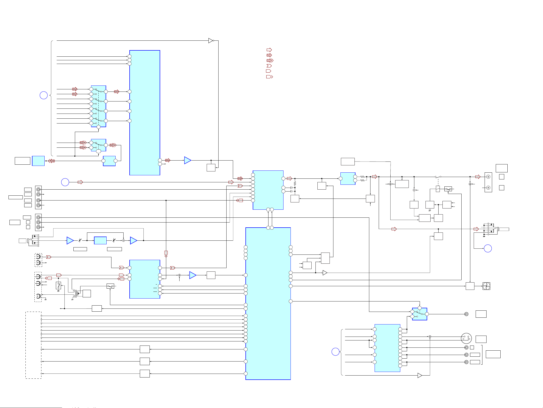
– Main Section –
DIGITAL OUT
OPTICAL
VIDEO(MD)
INPUT
J1201
MIC
IN L
IN R
OUT L
OUT R
VIDEO
L
R
HEAD
REC/PB
HEAD
ERASE
HEAD
B REC FWD
DVD DSP
SECTION
(Page 21)
OPTICAL
DIGITAL
DECK-A
PB
DECK-B
TC BLOCK
B SHUT
A SHUT
B PLAY
A PLAY
B HALF
A HALF
B REC REV
CAP M+
A TRG M+
IC501
OUT
J101
J1001
MREQ
IC301
D/A CONVERTER
MDI
MC
ML
IC305
TUNER
MIC-LEVEL
T601
RV1201
DIGITAL AUDIO SELECTOR
13
14
10
11
OPTICAL OUT SELECTOR
12
Q601
BIAS
OSC
3
2
6
5
IC303
5
Q608,609
SWITCH
1
1,2
IC1203
DIGITAL
ECHO
12
4
9
7
8
IC504
TIMING
Q602,603
RV1202
ECHO-LEVEL
DATA0
R-CH
R-CH
R-CH
TUNER
SECTION
(Page 23)
R-CH
R-CH
Q604
Q605
R-CH
PCMD
BCK-ZIBA
BCK
LRCK-ZIBA
LRCK
XCK
768FS
IEC958
DOUT
CDSEL
E
IC1201(1/2)
MIC AMP
A
14
TC12V
13 DATA
14 CLK
15 LAT
DATA(SEL)
2
BCK(SEL)
1
3
LRCK
16
MCLK
IC1201(2/2)
MIC AMP
REC/PB AMP
32 A-IN(L)
34 B-IN(L)
21 REC-OUT(L)
IC601
Q615,616
CAP M
DRIVE
Q617,618
B TRIG
DRIVE
Q613,614
A TRIG
DRIVE
IC505
BUFFER
7LOUT
8ROUT
RCH
26PB-OUT(L)
28EQ-OUT(L)
24REC-IN(L)
13A/B
14MUTE ON/OFF
15REC.MUTE OFF/ON
R-CH
IC303
AMS AMP
Q110
MUTE
Q108
Q610,611
AMS
DET
42 SUR1
DVD
3 INA1
TUNER
4 INB1
TC
5 INC1
LINE
6 IND1
GAME
7 INEX1
MIC
2MIC
8RECB1
IC1104(2/3)
MASTER CONTORL
56
SURR-SW
31 VOL-CLK
33 VOL-DATA2
32 VOL-DATA1
72 AMS-IN
76
PB-A/B
78
PB-MUTE
79
REC-MUTE
75 BAIS
77 TC-RELAY
B-SHUT81
A-SHUT
80
B-PLAY71
70
A-PLAY
69
B-HALF
68
A-HALF
B-REC.REV
67
B-REC.FWD
66
65
CAP M-CONT
61
B-TRIGB TRG M+
60
A-TRIG
• RCH is omitted due to same as LCH
• Signal Path
: FM
: DVD
: DIGITAL OUT
: PB(DECK A)
: PB(DECK B)
: REC(DECK B)
IC102
SOUND CONTROLLER
18LOUT
17
BBB1
16
BBA1
DATA
CLOCK
21 22
5 7
REAR/CEN
M61519-DATA
M61519-CLOCK
MUTE
TH201,Q216,217
OVERHEAT
DET
IC201
POWER AMP
V
C
Y
CB/R
CR/B
WIDE
10
11
DBFB
DET
RCH
4 V-IN
2 C-IN
6 Y-IN
12 CY-IN
14
CB-IN
16
CR-IN
RCH
IC503
VIDEO BUFFER
V-OUT.B
C-OUT
Y-OUT.B
CY-OUT.B 25
CB-OUT.B 22
CR-OUT.B 19
Q251
OVERLOAD
DET
30V-OUT.A
31
33
27Y-OUT.A
28
24CY-OUT.A
21CB-OUT.A
18CR-OUT.A
Q236,237
VIDEO SELECTOR
DC
DET
1
3
Q501,502
RCH
Q233,234
PROTECT
2
IC502
Q103
MUTE
DBFB
SW
Q101
52
51SW-MUTE
83LINE-MUTE
D734,735
AC4
84STK-MUTE
87REAR-RELAY
88FRONT-RELAY
50FNN
55VIDEO-SW
DET
Q702,703,707
LINE
AC
MUTE
Q701
DVD DSP
SECTION
(Page 21)
15
B
Q235
DET
RELAY
SW
7
RY281
MUTE
HP
MUTE
D230,231
Q232
Q152
Q281,282
AC
DET
+VH
AC3
RCH
RCH
R CH
HP
Q713,
Q708-710
FAN
SW
J503
VIDEO
OUT
Y
PB/C
PR/C
J502
S VIDEO
OUT
B
R
C
Y
TM201
F
FAN
J501
COMPONENT
VIDEO OUT
FRONT
SPEAKER
DVD SYS
SECTION
(Page 22)
L
R
J1101
PHONES
2424

6-2. Circuit Boards Location
d
HCD-RV600D/RV600DJ
THIS NOTE IS COMMON FOR PRINTED WIRING BOARDS AND SCHEMATIC DIAGRAMS.
(In addition to this, the necessary note is printed in each b lock.)
SUB TRANSFORMER board
TRANSFORMER board
PANEL board
REMOTE board
MICROPHONE board
SUB PANEL board
SENSOR board
DIODE board
MOTOR board
TC board
DRIVER board
RF board
MAIN board
MB board
Note on Schematic Diagram:
• All capacitors are in µF unless otherwise noted. pF: µµF
50 WV or less are not indicated except for electrolytics
and tantalums.
• All resistors are in Ω and 1/
specified.
f
•
• 5 : fusible resistor.
• C : panel designation.
Note: The components identified by mark 0 or dotted line
• A : B+ Line.
• B : B– Line.
• H : adjustment for repair.
•Voltages and waveforms are dc with respect to ground
•Voltages are taken with a VOM (Input impedance 10 MΩ).
•Waveforms are taken with a oscilloscope.
• Circled numbers refer to waveforms.
• Signal path.
•Abbreviation
: internal component.
with mark 0 are critical for safety.
Replace only with part number specified.
under no-signal (detuned) conditions.
Voltage variations may be noted due to normal produc-
tion tolerances.
Voltage variations may be noted due to normal production tolerances.
F : FM
f : AM
E : PB (DECK A)
d : PB (DECK B)
G : REC (DECK B)
c : digital out
g : MD (VIDEO)
EA : Saudi Arabia model
MY : Malaysia model
SP : Singapore model
TH : Thai model
MX : Mexican model
E51 : Chilean and Peruvian model
E3 : 240V AC Area in E model
4
W or less unless otherwise
Note on Printed Wiring Boards:
• X : parts extracted from the component side.
• : Pattern from the side which enables seeing.
• Indication of transistor.
C
B
B
Q
E
CE
These are omitted.
These are omitted.
REG board
VIDEO board
FRONT AMP boar
2525

HCD-RV600D/RV600DJ
6-3. Printed Wiring Board – RF Board –
• See page 25 for Circuit Boards Location.
• Semiconductor
Location
Ref. No. Location
D001 B-5
D002 B-5
IC001 A-5
Q001 C-3
Q002 C-3
IC001
(Page 28)
2626
HCD-RV600D/RV600DJ
6-4. Schematic Diagram – RF Board –
CN001
24P
(KHM-240AAA)
• See page 53 for Wavefoms. • See page 62 for IC Block Diagrams.
R023
JL005
C008
B
C009
B
R001
100 E
JL007
820
H
C
p
2
0
5600p B
5600p B
2200p B
2200p B
2200p B
2200p B
180p CH
0
0
0
0
0
0
0
0
2
0
2
0
C
R025
100
R024
C019
R022
220
C018
C017
C016
C015
C014
C042
R014
R013
R012
R011
R018
R017
R016
R015
CN002
29P
C027
B
0
H
H
H
C
C
C
p
p
p
2
2
2
2
2
2
1
2
2
2
23
0
0
0
C
C
C
C025
B
B
JL004
4
2
0
C
B
6
2
0
C
IC001
CXD1881AR
C
C031
R026
1000p
12k
CH
8
2
C030
B
C029
B
E
B
C013
B
C006
R027
0
R028
0
R029
0
C032
C033
B
JL006
JL003
B
C034
JL002
JL001
B
C049
R032
100
B
C035
B
10V
C005
C012
10V
B
CN003
0
R035
00
R041
1k
9P
R019 R020
R005
47k
3
3
3
0
0
R
Q001 Q002
2SB1132-T100-QR 2SB1132-T100-QR
L001
C010
1000p
C002 C004
D001 D002
1SS355TE-17 1SS355TE-17
CH
16V
IOP1IOP2
C001
6.3V
R006
470
C041
B
C040
B
R021
0
R009
47k
3
3
R008R004
3333
07
0
R
L002
16V
1000p
V
.3
3
6
0
0
C
R010
470
C011
CH
C039 C038
R033
0
C036
C037
R034
330p
CH
B
10M
(KHM-240AAA)
2727

HCD-RV600D/RV600DJ
Ver 1.2 2003.10
6-5. Printed Wiring Board – MB Board (Side A) –
• See page 25 for Circuit Boards Location.
(Page 26)
CN501
IC206
IC701
IC215
IC904
IC902
TH
26
50
IC906
EXCEPT
TH
25
IC901
51 75
X902
IC509
• Semiconductor
1
100
76
Location
Ref. No. Location
D201 E-1
D301 E-3
D302 E-3
IC206 C-1
IC215 C-2
IC301 E-2
IC303 D-2
IC509 B-4
IC701 B-1
IC901 C-3
IC902 C-2
IC904 C-2
IC906 D-3
Q903 E-4
Q904 E-4
D201
IC303
(Page 42)
IC301
Q
(Page 42)
2828
(Page 38)
E
E
(Page 38)
7
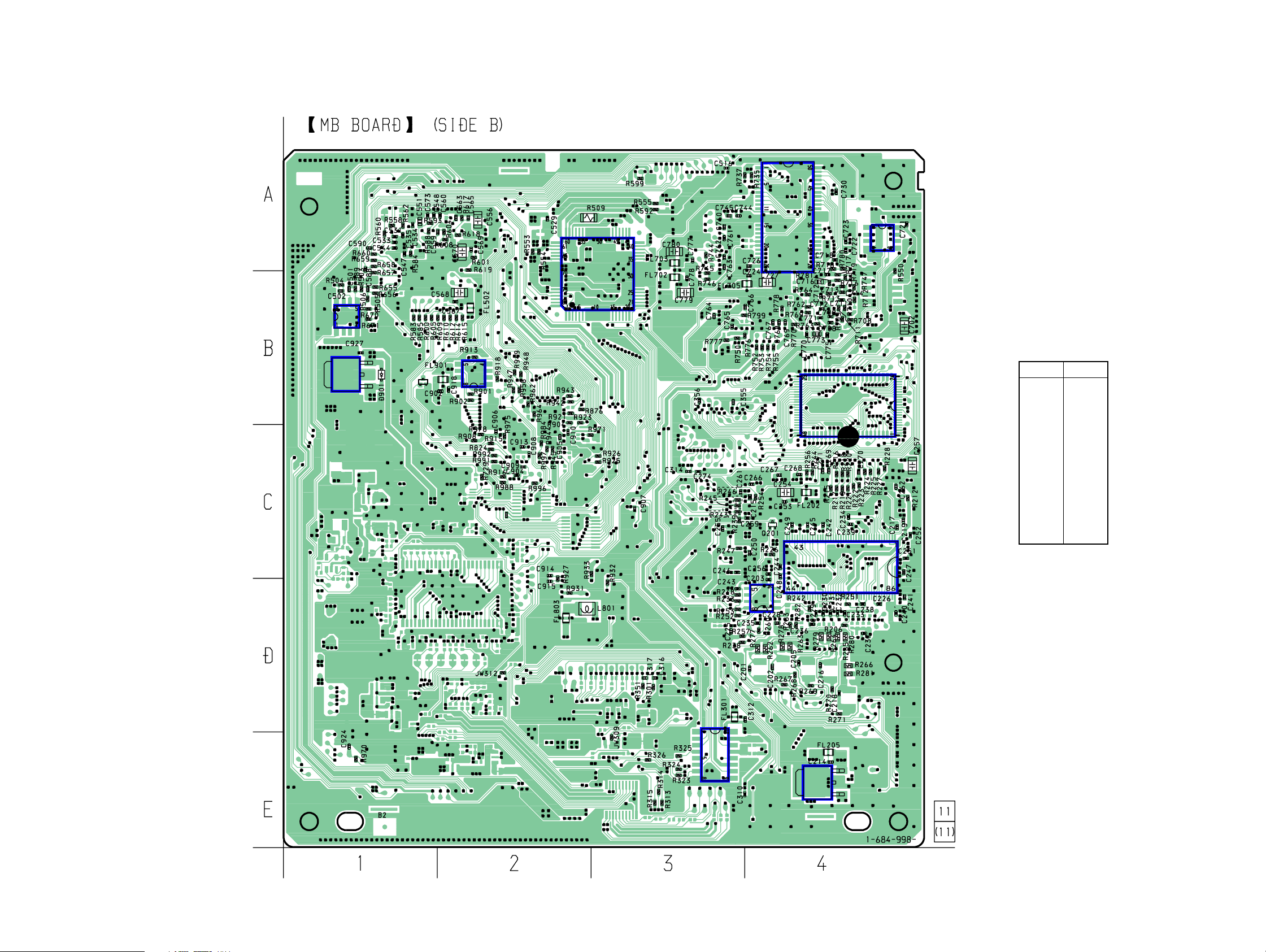
6-6. Printed Wiring Board – MB Board (Side B) –
• See page 25 for Circuit Boards Location.
IC503
IC907
Q901
E
IC903
HCD-RV600D/RV600DJ
Ver 1.2 2003.10
IC706
IC703
IC501
• Semiconductor
Location
Ref. No. Location
D901 B-1
TH
TH
IC203
IC205
IC202
IC202 C-4
IC203 D-4
IC205 B-4
IC210 E-4
IC305 E-3
IC501 B-3
IC503 B-1
IC703 A-4
IC706 A-4
IC903 B-2
IC907 B-1
Q907 B-1
IC305
IC210
2929
HCD-RV600D/RV600DJ
Ver 1.2 2003.10
6-7. Schematic Diagram – MB Board (1/6) –
• See page 56 for IC Pin Function Description.
IC703(2/2)
NJM3404AM-TE2
R544
100k
C523
R545
100k
1500p
B
FL706
POWER-EMIS
C729
10 10V
R702
FL703
POWER-EMIS
FL704
POWER-EMIS
R767
47k
C774
R765
0.0047
22k
B
R799
R540
10k
R541
100k
R538C521
100k1500p B
R701
0
0
C780 C777
10
0.1
10V
F
POWER-EMIS
C776
C781
0.1 F
100 4V
SL703
C772
0.1 F
1M
R764
C773
0.47
B
C771
0.047
B
R762
0
R759
0
R758
0
R757
R756
0
R766
R755
0
0
R763
8.2k
CL791
R777
R550
0
B
705
C701
C
100
0.01
4V
FL701
POWER-EMIS
FL702
C779
10 10V
R769
2.2k
22k
0
R754
0
R753
0
R752
0
C766
100p
R750
10k
0
C778
0.1
F
C775
0.1
F
C770
0.1
F
0
R770
C769
0.1
F
R778
100k
C768
0.1
F
C767
0.1
F
CL787
CL786
CL785
0
CH
R776
C765
0.1
F
TP701
IS
-EM
ER
FL705
TP703
C715
R700
0.0015
8.2k
B
R726
C720 C721
0.1 B 0.1 F
100k
R727
3.3k
R728
F
0.1
722
C
R725
1.8k
R724
1k
IC703(1/2)
C703
0.1
B
C706
C702
R707
0.1
10
100
F
10V
B
C709
0.01
470k
0.1
F
708
708
C
R
R709
150k
C711
0.01 B
C712
100p
CH
0k
R712
R710
10k
R711
2.2k
1
10k
713
R
CL703
C752
0.1
0k
1
4
71
R
NJM3404AM-TE2
R781
F
F
0.1
0.1
33k
714
0k
747
C713
C
1
R
715
R
R721
33k
1k
R720
C717
B
0.01 B
0
R718
CL701
10k
0.47
F
0
C716
100k
0.1
R780
717
R
1k
719
R
8
C71
IC701
TMC57929PGF-RDP
716
100
R
33k
748
R
W
PO
B
C727
0.1
10
10k
F
0.1
3
C72
C724
10V
728
C
0.1 F
IC706
MSM51V18165F -60TSKR1
C725 C726
0.1 F 0.1 F
C730
0.1 F
R730
22
C740
R731
0.1 F
22
C741
0.1 F
R732
10k
C742
0.1 F
R771
10k
R773
10k
C743
0.1 F
R735
R774
10k
R779
10k
R784
10k
R743
10k
R737
10k
C744
0.1 F
R741
22
R742
22
C745
0.1 F
22
7
CL77
22
744
R
0.1
F
C763C764
0.1
F
R746
C762
0.1
F
47k
R745
47k
C760
C761
0.1
0.1
F
F
3030
 Loading...