

Page 1
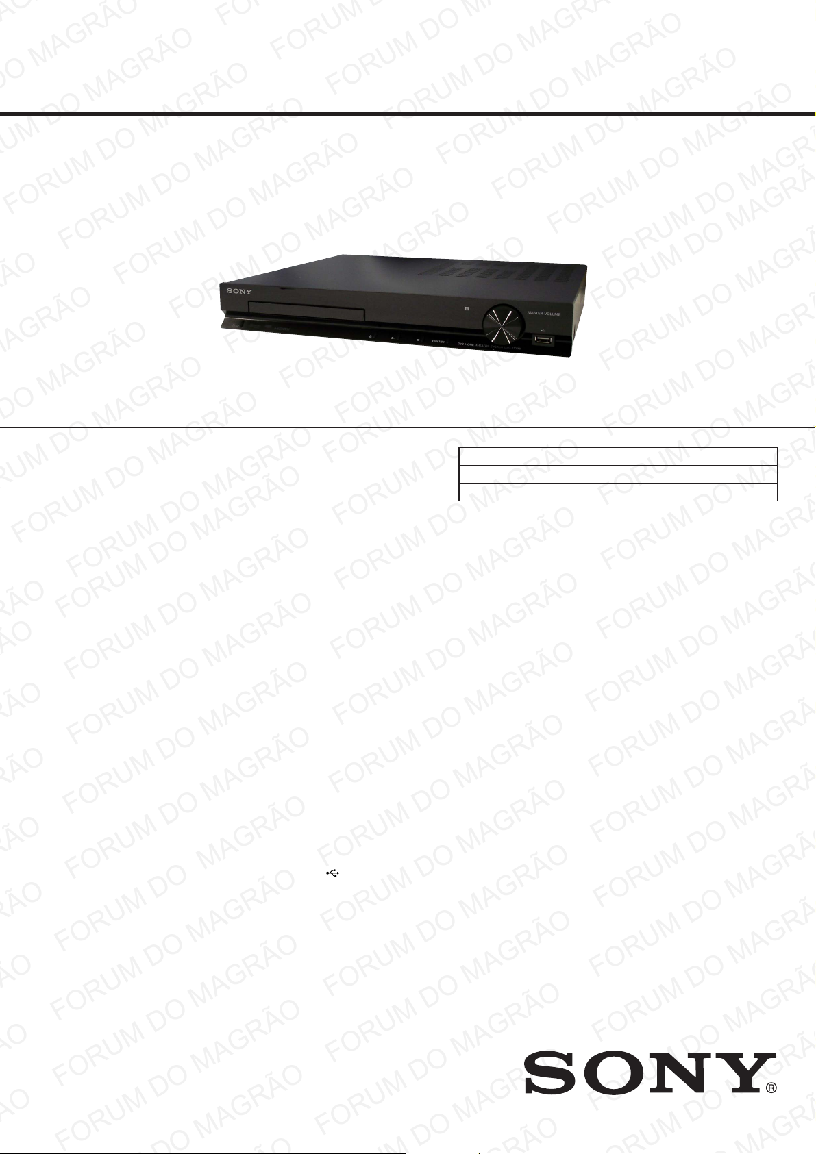
HBD-TZ135
SERVICE MANUAL
Ver. 1.1 2011.04
• HBD-TZ135 is the amplifi er, DVD/CD and tuner
section in DAV-TZ135.
This system incorporates with Dolby* Digital and Dolby Pro Logic
adaptive matrix surround decoders.
* Manufactured under license from Dolby Laboratories.
Dolby, Pro Logic, and the double-D symbol are trademarks of
Dolby Laboratories.
This system incorporates High-Defi nition Multimedia Interface
(HDMI™) technology.
HDMI, the HDMI logo and High-Defi nition Multimedia Interface are
trademarks or registered trademarks of HDMI Licensing LLC.
“BRAVIA” is a trademark of Sony Corporation.
MPEG Layer-3 audio coding technology and patents licensed from
Fraunhofer IIS and Thomson.
Windows Media is a registered trademark of Microsoft Corporation in
the United States and/or other countries.
Canadian Model
AEP Model
UK Model
E Model
Australian Model
Chinese Model
Model Name Using Similar Mechanism HBD-TZ130
DVD Drive Mechanism Type CDM85
Optical Pick-up Name KHM-313
Amplifi er Section
POWER OUTPUT (rated):
Front L + Front R 32 W + 32 W (at 3
ohms, 1 kHz, 1% THD)
POWER OUTPUT (reference):
Front L/Front R/
Surround L/Surround
R: 43 watts (per channel
at 3 ohms, 1 kHz)
Center: 89 watts (per
channel at 6 ohms, 1 kHz)
Subwoofer: 89 watts (at
6 ohms, 100 Hz)
Inputs
TV/CABLE : Pin jack
9-893-082-02
2011D04-1
2011.04
©
Sony Corporation
Published by Sony Techno Create Corporation
SPECIFICATIONS
CD/DVD System
Laser Diode Properties
Emission Duration:
Continuous
Laser Output*: Less
than 1,000 μW
* This output is the value measurement at a dis-
tance of 200 mm from the objective lens surface on the Optical Pick-up Block with 7 mm
aperture.
USB Section
(USB) port:
Maximum current: 500 mA
Tuner Section
System PLL quartz-locked
digital synthesizer
Tuning range
North American models:
87.5 MHz - 108.0 MHz
(100 kHz step)
Other models: 87.5 MHz - 108.0 MHz
(50 kHz step)
Antenna (aerial) terminals
75 ohms, unbalanced
Intermediate frequency
10.7 MHz
– Continued on next page –
DVD RECEIVER
Page 2
HBD-TZ135
Ver. 1.1
Video Section
Outputs VIDEO: Pin jack
HDMI OUT: HDMI
19-pin
General
Power requirements
North American and Mexican models:
120 V AC, 60 Hz
Latin American models:
110 V - 240 V AC,
50/60 Hz
Argentine models: 220 V - 240 V AC,
50/60 Hz
Brazilian models: 127 V - 240 V AC,
50/60 Hz
Other models: 220 V - 240 V AC,
50/60 Hz
Power consumption On: 67 W
Standby: <1 W*
* Valid when the system is in the following status:
– [Control for HDMI] is set to [Off].
Dimensions (approx.) 360 mm × 56 mm ×
342 mm (14
2
incl. projecting parts
Mass (approx.) 2.6 kg (5 lb. 12 oz.)
1
/4 in × 13 1/2 in) (w/h/d)
1
/4 in ×
Design and specifi cations are subject to
change without notice.
SAFETY-RELATED COMPONENT WARNING!
COMPONENTS IDENTIFIED BY MARK 0 OR DOTTED LINE
WITH MARK 0 ON THE SCHEMATIC DIAGRAMS AND IN
THE PARTS LIST ARE CRITICAL TO SAFE OPERATION.
REPLACE THESE COMPONENTS WITH SONY PARTS
WHOSE PART NUMBERS APPEAR AS SHOWN IN THIS
MANUAL OR IN SUPPLEMENTS PUBLISHED BY SONY.
ATTENTION AU COMPOSANT AYANT RAPPORT
À LA SÉCURITÉ!
LES COMPOSANTS IDENTIFIÉS PAR UNE MARQUE 0 SUR
LES DIAGRAMMES SCHÉMATIQUES ET LA LISTE DES
PIÈCES SONT CRITIQUES POUR LA SÉCURITÉ DE FONCTIONNEMENT. NE REMPLACER CES COMPOSANTS QUE
PAR DES PIÈCES SONY DONT LES NUMÉROS SONT DONNÉS DANS CE MANUEL OU DANS LES SUPPLÉMENTS
PUBLIÉS PAR SONY.
2
SPECIAL COMPONENT NOTICE
The components identifi ed by mark 9 contain confi dential infor-
mation.
Strictly follow the instructions whenever the components are repaired and/or replaced.
NOTICE POUR COMPOSANTS SPÉCIAUX
Les composants identifi és par la marque 9 contiennent des infor-
mations confi dentielles.
Suivre scrupuleusement les instructions chaque fois qu’un composant est remplacé et / ou réparé.
Page 3
HBD-TZ135
Ver. 1.1
Laser component in this product is capable of emitting radiation
exceeding the limit for Class 1.
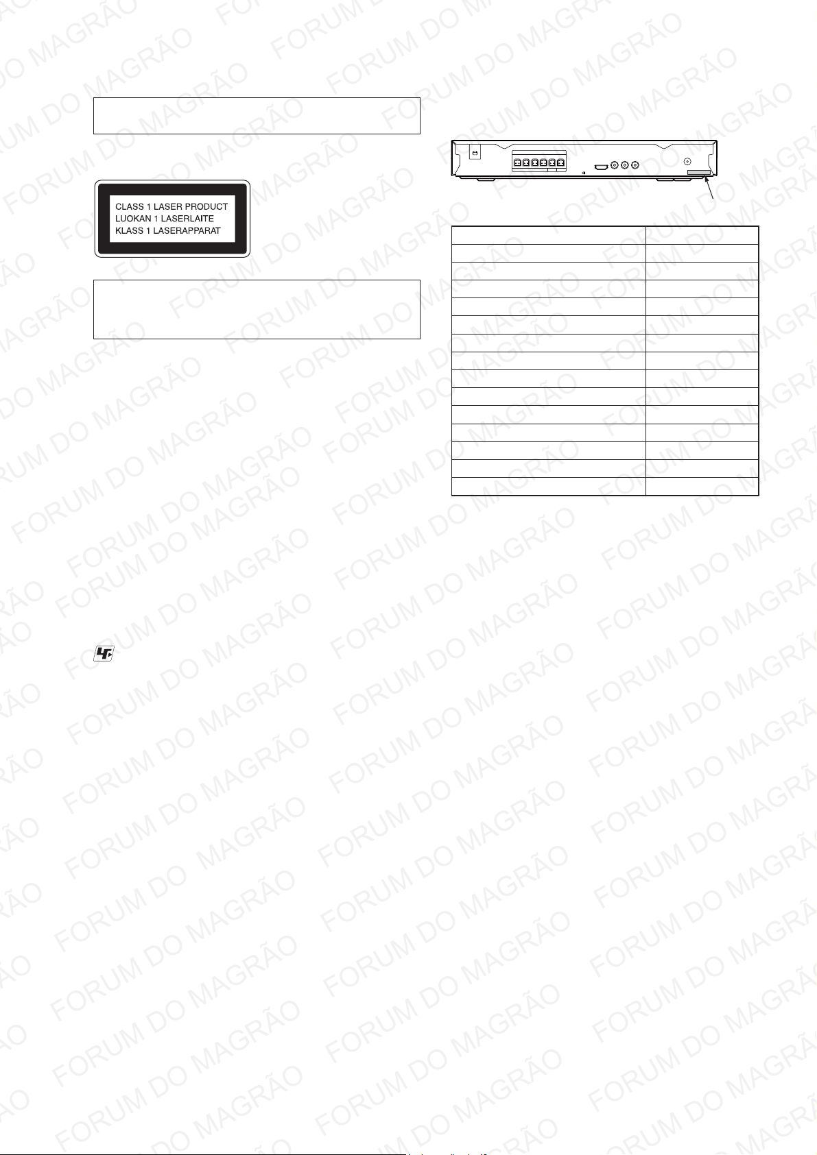
For European, Chinese and Mexican models:
This appliance is classifi ed as
a CLASS 1 LASER product.
This marking is located on the
rear exterior of unit.
CAUTION
Use of controls or adjustments or performance of procedures
other than those specifi ed herein may result in hazardous radia-
tion exposure.
NOTES ON CHIP COMPONENT REPLACEMENT
• Never reuse a disconnected chip component.
• Notice that the minus side of a tantalum capacitor may be dam-
aged by heat.
FLEXIBLE CIRCUIT BOARD REPAIRING
• Keep the temperature of soldering iron around 270 °C during
repairing.
• Do not touch the soldering iron on the same conductor of the
circuit board (within 3 times).
• Be careful not to apply force on the conductor when soldering
or unsoldering.
UNLEADED SOLDER
Boards requiring use of unleaded solder are printed with the leadfree mark (LF) indicating the solder contains no lead.
(Caution: Some printed circuit boards may not come printed with
the lead free mark due to their particular size)
: LEAD FREE MARK
Unleaded solder has the following characteristics.
• Unleaded solder melts at a temperature about 40 °C higher
than ordinary solder.
Ordinary soldering irons can be used but the iron tip has to be
applied to the solder joint for a slightly longer time.
Soldering irons using a temperature regulator should be set to
about 350 °C.
Caution: The printed pattern (copper foil) may peel away if
the heated tip is applied for too long, so be careful!
• Strong viscosity
Unleaded solder is more viscous (sticky, less prone to fl ow)
than ordinary solder so use caution not to let solder bridges
occur such as on IC pins, etc.
• Usable with ordinary solder
It is best to use only unleaded solder but unleaded solder may
also be added to ordinary solder.
MODEL IDENTIFICATION
– Back Cabinet –
Parts No.
Model Part No.
MX model GSE200276-0019
SP model GSE200276-0020
AEP, UK model GSE200276-0021
RU model GSE200276-0022
AUS model GSE200276-0023
TH model GSE200276-0024
CH model GSE200276-0025
E32 model GSE200276-0026
CND model GSE200276-0028
E3, SAF model GSE200276-0029
E12 model GSE200276-0030
PH model GSE200276-0031
AR model GSE200276-0032
BR model GSE200276-0033
• Abbreviation
AR : Argentina model
AUS : Australian model
BR : Brazilian model
CH : Chinese model
CND : Canadian model
E3 : 240V AC area in E model
E12 : 220 – 240V AC area in E model
E32 : 110 – 240V AC area in E model
MX : Mexican model
PH : Philippines model
RU : Russian model
SAF : South African model
SP : Singapore model
TH : Thai model
3
Page 4

HBD-TZ135
TABLE OF CONTENTS
1. SERVICING NOTES
............................................. 5
2. DISASSEMBLY
2-1. Top Cover ....................................................................... 9
2-2. Door ................................................................................ 10
2-3. Front Cabinet Section ..................................................... 10
2-4. CONTROL Board, STANDBY Board ............................ 11
2-5. USB Board ...................................................................... 11
2-6. MAIN Board ................................................................... 12
2-7. POWER Board ................................................................ 12
2-8. DVD Mechanism Deck Section ...................................... 13
2-9. Optical Pick-up ............................................................... 13
3. DIAGRAMS
3-1. Block Diagram ................................................................ 15
3-2. Printed Wiring Board –Main Section (1/2)– ................... 16
3-3. Printed Wiring Board –Main Section (2/2)– ................... 17
3-4. Schematic Diagram –Main Section (1/2)– ...................... 18
3-5. Schematic Diagram –Main Section (2/2)– ...................... 19
3-6. Printed Wiring Boards –Display Section– ...................... 20
3-7. Schematic Diagram –Display Section– .......................... 21
3-8. Printed Wiring Board –Power Section– .......................... 22
3-9. Schematic Diagram –Power Section– ............................. 23
4. EXPLODED VIEWS
4-1. Overall Section ............................................................... 24
4-2. Front Cabinet Section ..................................................... 25
4-3. Chassis Section ............................................................... 26
4-4. DVD Mechanism Deck Section ...................................... 27
4
Page 5
SECTION 1
SERVICING NOTES
HBD-TZ135
NOTES ON HANDLING THE OPTICAL PICK-UP
BLOCK OR BASE UNIT
The laser diode in the optical pick-up block may suffer electrostatic break-down because of the potential difference generated by
the charged electrostatic load, etc. on clothing and the human body.
During repair, pay attention to electrostatic break-down and also
use the procedure in the printed matter which is included in the
repair parts.
The fl exible board is easily damaged and should be handled with
care.
NOTES ON LASER DIODE EMISSION CHECK
The laser beam on this model is concentrated so as to be focused
on the disc refl ective surface by the objective lens in the optical
pickup block. Therefore, when checking the laser diode emission,
observe from more than 30 cm away from the objective lens.
LASER DIODE AND FOCUS SEARCH
1. Open the case and turn POWER on with no disc inserted.
2. Confi rm that the following operation is performed while ob-
serving the objecting lens from the clearance of DVD mechanism deck.
1) Confi rm that laser beam is spread.
2) Up and down motion of the objective lens. (2 times)
DISC TRAY LOCK
The disc tray lock function for the antitheft of an demonstration
disc in the store is equipped.
Setting Procedure :
1. Press the [
2. Press the [FUNCTION] button to set DVD/CD function.
3. Insert a disc.
4. Press the [x] button and the [Z] button simultaneously for fi ve
seconds.
5. The message “LOCKED” is displayed and the tray is locked.
Releasing Procedure :
1. Press the [x] button and the [Z] button simultaneously for fi ve
seconds again.
2. The message “UNLOCKED” is displayed and the tray is un-
locked.
Note: When “LOCKED” is displayed, the tray lock is not released by
turning power on/off with the [
] button to turn the set on.
?/1
?/1
] button.
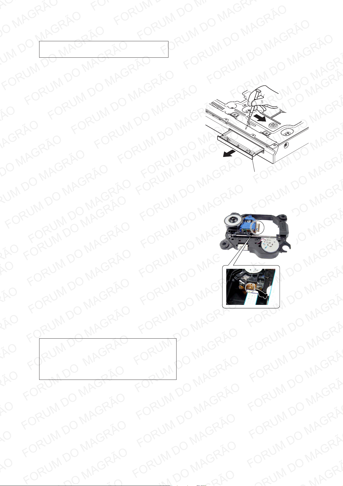
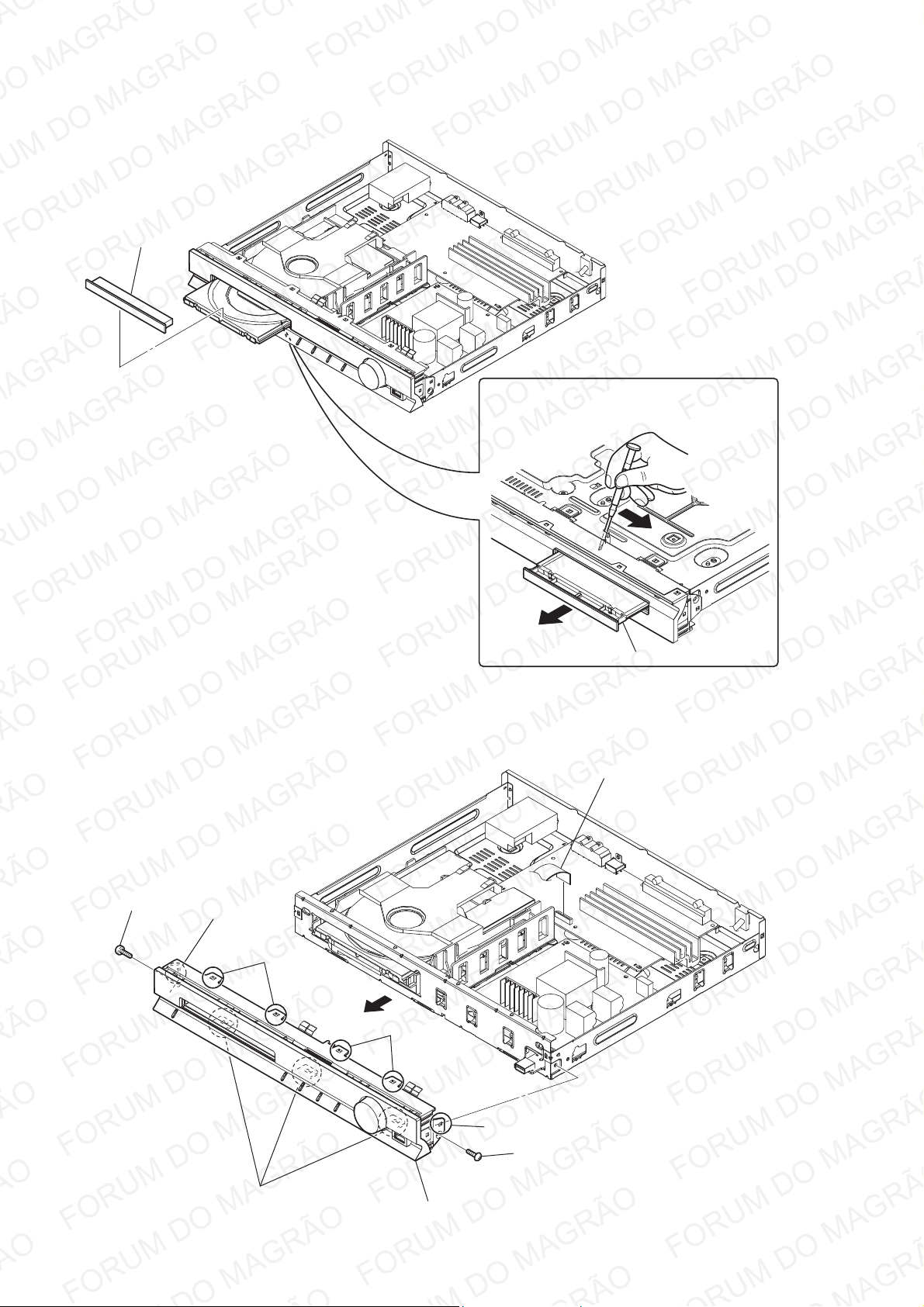
How to open the disc tray when power switch turns off
Insert a tapering driver into the aperture of the unit bottom, and
slide it in the direction of the arrow.
Insert a screwdriver from between the front panel and
the chassis and slide the rod in the direction of the arrow.
disc tray
Precaution when installing a new OP unit/
Precaution before unsoldering the static electricity
prevention solder bridge
On cleaning discs, disc/lens cleaners
• Do not use cleaning discs or disc/lens cleaners (including wet
or spray types). These may cause the apparatus to malfunction.
IMPORTANT NOTICE
Caution: This system is capable of holding a still video image or onscreen display image on your television screen indefi nitely. If you leave
the still video image or on-screen display image displayed on your TV
for an extended period of time you risk permanent damage to your television screen.
Projection televisions are especially susceptible to this.
When installing a new OP unit, be sure to connect the wire (fl at
type) (24 core) fi rst of all before removing the static electricity
prevention solder bridge by unsoldering.
Remove the static electricity prevention solder bridge by unsoldering after the wire (fl at type) (24 core) has already been connected.
(Do not remove nor unsolder the solder bridge as long as the OP
unit is kept standalone.)
5
Page 6
HBD-TZ135
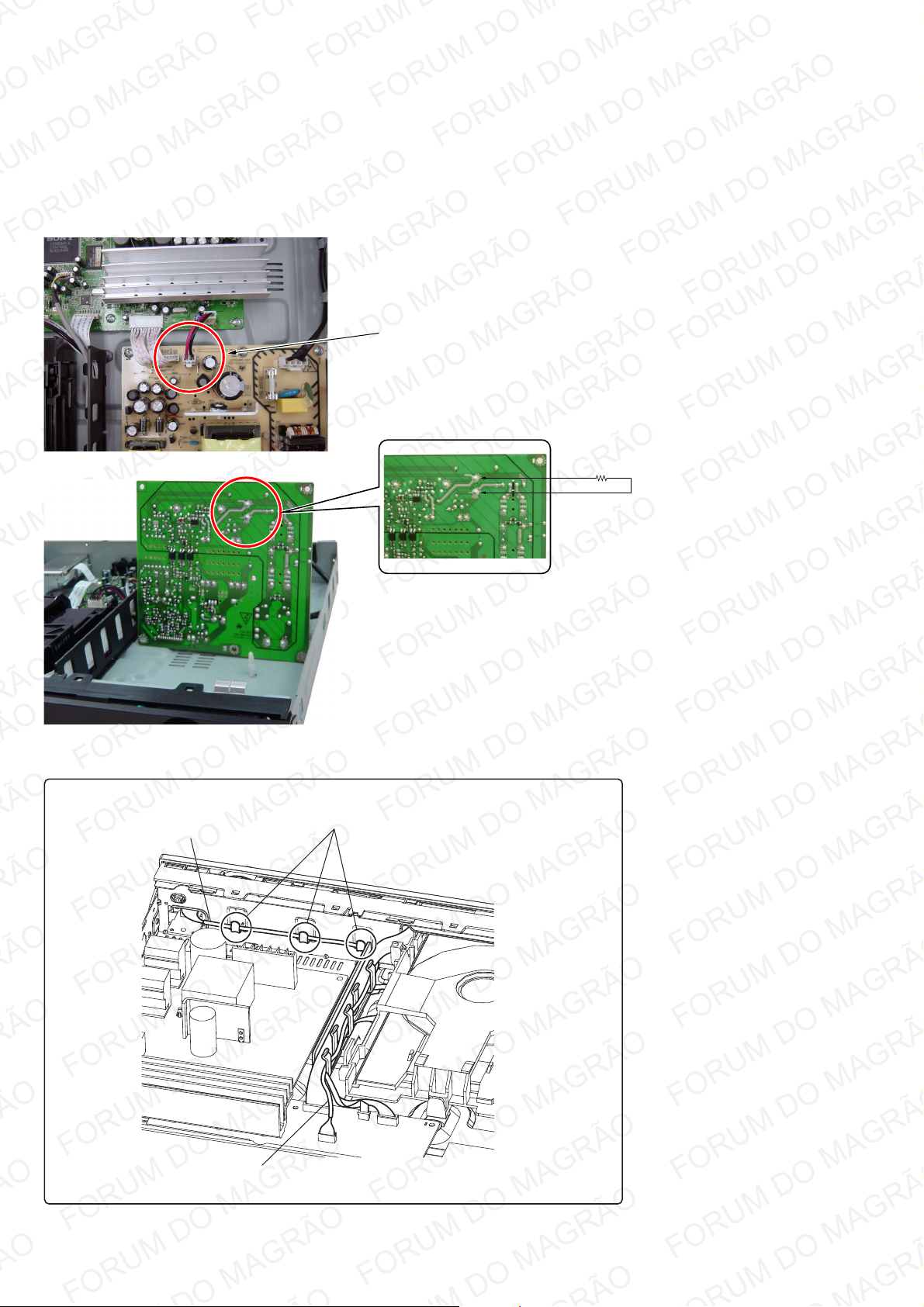
Discharge the charged electricity in capacitors to prevent electric shock as follows
When disassembling the machine, be sure to discharge the charged electricity in the following capacitors.
Use a resistor of 800 ohms, 2 Watts for discharging the following capacitors.
POWER board
C906: 390V
C936, C944 and CN902: 32V
Point of capacitor discharge for C936 and C944:
Connect to the red and black wires of CN902.
800:/2W
Arranging the USB wire
USB wire
Point of capacitor discharge for C906:
Connect to the foot of C906.
Have the USB wire spread on the inside
of the claws of the chassis.
USB wire
6
Page 7
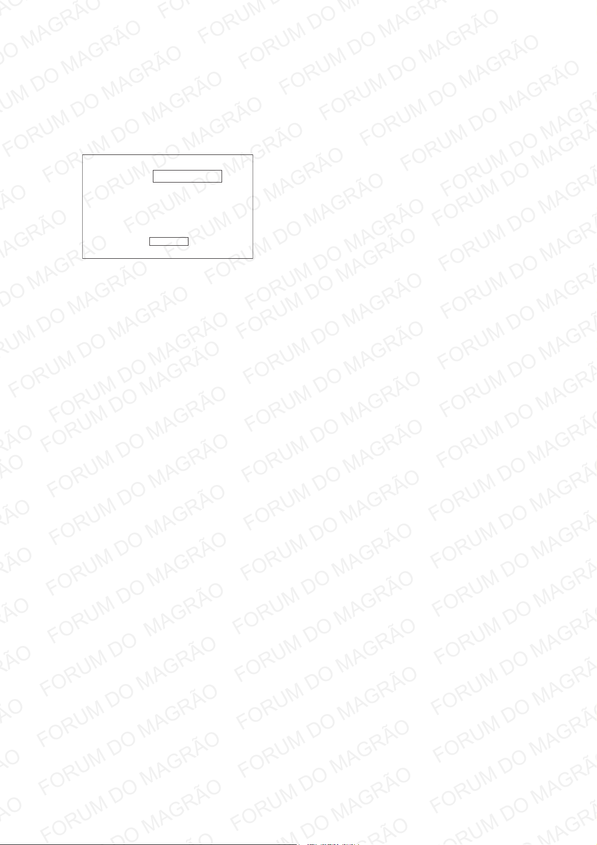
Version display
• Confi rmation procedure of version only
1. Press the [
2. Press the [EJECT] button. (State of “Tray open”)
3. After press the “STOP” button, the “DISPLAY” button press.
4. The version information appears to the TV.
Model No. DAV-TZ135 CEL
Release : 2010.08.26C
MPEG : 2.15.23 MCU : 2.15.24
Region : 2 HdcpKey : Yes
5. Press the “ENTER” button on the remote.
6. The system will return to normal mode.
] button to turn the set on.
?/1
OK
HBD-TZ135
7
Page 8
HBD-TZ135
DISASSEMBLY
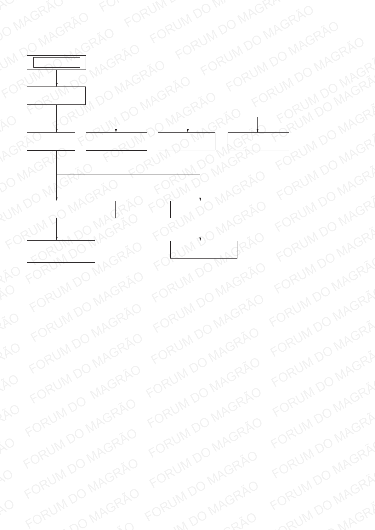
• This set can be disassembled in the order shown below.
SET
2-1. TOP COVER
(Page 9)
SECTION 2
2-2. DOOR
(Page 10)
2-3. FRONT CABINET SECTION
(Page 10)
2-4. CONTROL BOARD,
STANDBY BOARD
(Page 11)
2-5. USB BOARD
(Page 11)
2-6. MAIN BOARD
(Page 12)
2-8. DVD MECHANISM DECK SECTION
(Page 13)
2-9. OPTICAL PICK-UP
(Page 13)
2-7. POWER BOARD
(Page 12)
8
Page 9
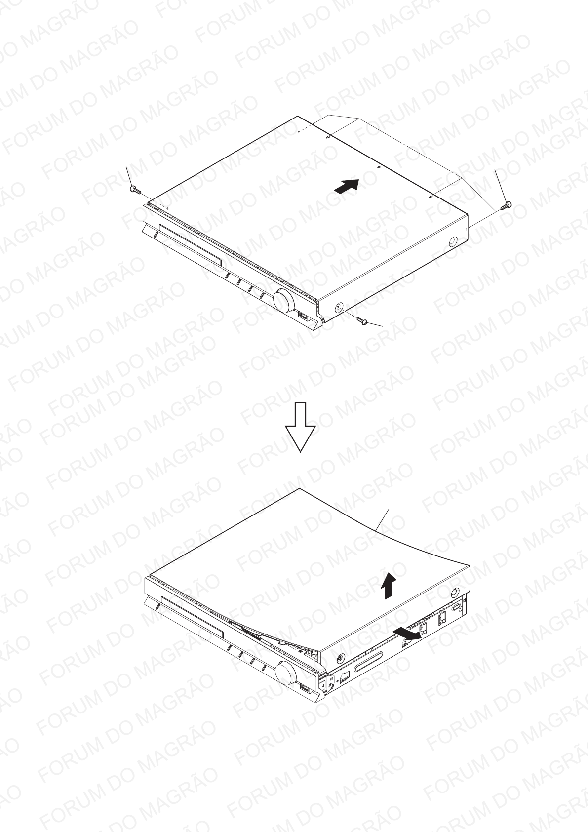
Note: Follow the disassembly procedure in the numerical order given.
2-1. TOP COVER
HBD-TZ135
2 screw
(case screw)
3 four screws
(+BVTT 3 u6)
4
1 screw
(case screw)
7 top cover
6
5 Raise one side of the case.
9
Page 10
HBD-TZ135
2-2. DOOR
3 door
Insert a screwdriver from between the front panel
and the chassis and slide the rod in the direction
of the arrow.
2-3. FRONT CABINET SECTION
2 screw
(+BVTT 3 u6)
8 claw
7 two claws
1
2
disc tray
1 wire (flat type) (15 core)
(CON302)
10
9
6 two claws
4 claw
3 screw
(+BVTT 3 u6)
5 three claws
0 front cabinet section
Page 11
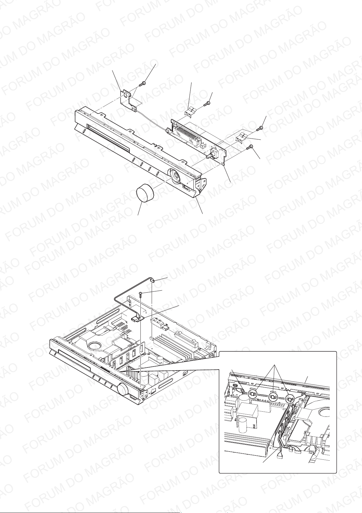
2-4. CONTROL BOARD, STANDBY BOARD
HBD-TZ135
9 STANDBY board
8 three screws
(+BVTP 2.6 (3CR))
1 volume knob
3 grounding spring
2 screw
(+BVTP 2.6 (3CR))
4 two screws
(+BVTP 2.6 (3CR))
5 grounding spring
6 four screws
(+BVTP 2.6 (3CR))
7 CONTROL board
0 front cabinet assy
2-5. USB BOARD
1 CON103 (5P)
2 screw
(+BVTT 3 u7)
3 USB board
Arranging the USB wire
Have the USB wire spread on the inside
of the claws of the chassis.
USB wire
front cabinet
USB wire
11
Page 12
HBD-TZ135
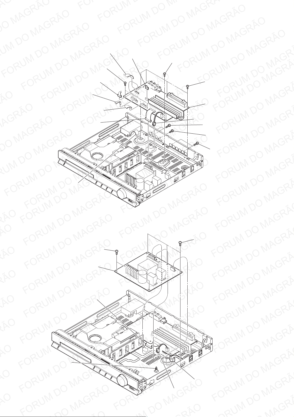
2-6. MAIN BOARD
6 wire (flat type) (24 core)
(CON100)
0 three screws
(+BVTT 3 u7)
8 CON103 (5P)
qa heat sink screw
4 wire (flat type) (5 core)
(CON101)
3 wire (flat type) (15 core)
(CON302)
7 wire (flat type) (9 core)
(CON301)
2-7. POWER BOARD
5 CON102 (6P)
2 CN901 (11P)
9 four screws
(+BVTT 3 u7)
qg MAIN board
1 CN902 (2P)
qs two screws
(+P 3 u10)
qd screw
(+BVTT 3 u6)
qf two screws
(+P 3 u10)
7 POWER board
6 spacer
4 two screws
(+BVTT 3 u7)
3 CN901 (11P)
5 three screws
(+BVTT 3 u7)
1 CN900 (2P)
12
2 CN902 (2P)
Page 13
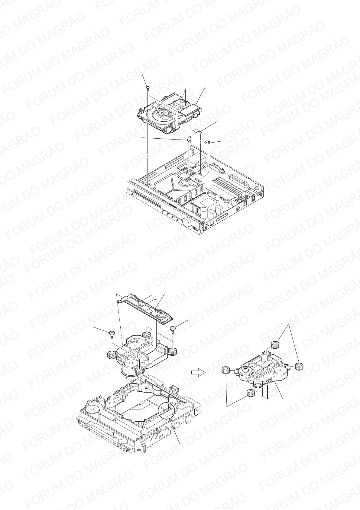
2-8. DVD MECHANISM DECK SECTION
4 three screws
(+BVTT 3 u7)
HBD-TZ135
5 DVD mechanism deck section
1 wire (flat type) (24 core)
(CON100)
3 CON102 (6P)
2-9. OPTICAL PICK-UP
2 wire (flat type) (5 core)
(CON101)
2 FFC holder
3 two screws
(PTP 2 u 5)
4 two screws
(PTP 2 u 5)
1 two claws
6 two insulators
5 two insulators
7 optical pick-up
(KHM-313)
13
Page 14
HBD-TZ135
Ver. 1.1
SECTION 3
DIAGRAMS
THIS NOTE IS COMMON FOR PRINTED WIRING BOARDS AND SCHEMATIC DIAGRAMS.
(In addition to this, the necessary note is printed in each block.)
For Printed Wiring Boards.
Note:
•
(The other layers’ patterns are not indicated.)
: Pattern from the side which enables seeing.
Caution:
Pattern face side:
(SIDE B)
Parts face side:
(SIDE A)
Parts on the pattern face side seen
from the pattern face are indicated.
Parts on the parts face side seen from
the parts face are indicated.
For Schematic Diagrams.
Note:
• All capacitors are in μF unless otherwise noted. (p: pF) 50
WV or less are not indicated except for electrolytics and
tantalums.
• All resistors are in Ω and 1/4 W or less unless otherwise
specifi ed.
Note: The components identifi ed by mark 0 or
dotted line with mark 0 are critical for safety.
Replace only with part number specifi ed.
Note: Les composants identifi és par une marque
0 sont critiques pour la sécurité.
Ne les remplacer que par une piéce portant
le numéro spécifi é.
14
Page 15
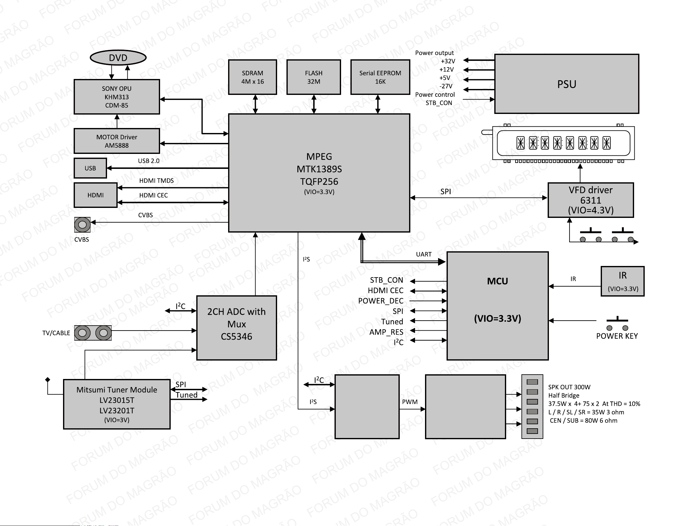
3-1. BLOCK DIAGRAM
HBD-TZ135
(VIO=3.3V)
Digital Audio
Processor
TSA5508B
(VIO=3.3V)
STM8/64K
48Pin
Digital Power AMP
TAS5342LA x 2
HBD-TZ135
1515
Page 16
HBD-TZ135
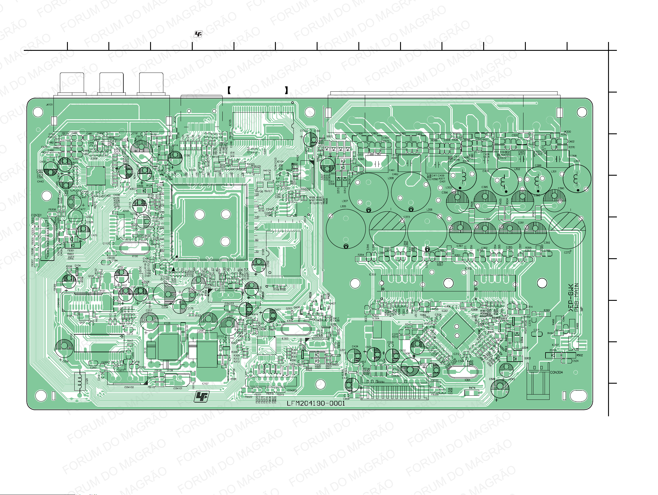
3-2. PRINTED WIRING BOARD – MAIN Section (1/2) –
• : Uses unleaded solder.
MAIN BOARD (SIDE A)
234567891011121314
1
A
B
C
D
E
F
G
H
I
HBD-TZ135
1616
Page 17
HBD-TZ135
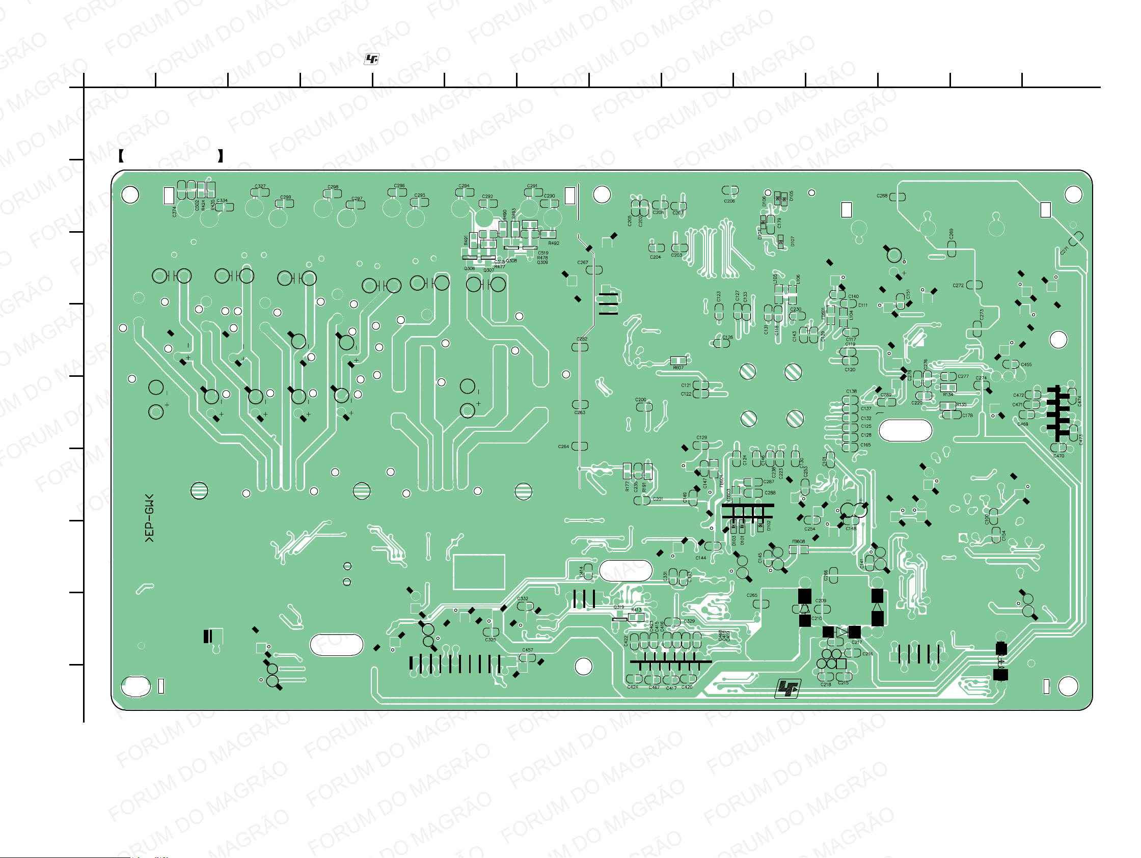
3-3. PRINTED WIRING BOARD – MAIN Section (2/2) –
1
234567891011121314
A
MAIN BOARD (SIDE B)
B
C
D
• : Uses unleaded solder.
E
F
G
H
I
HBD-TZ135
1717
Page 18
HBD-TZ135
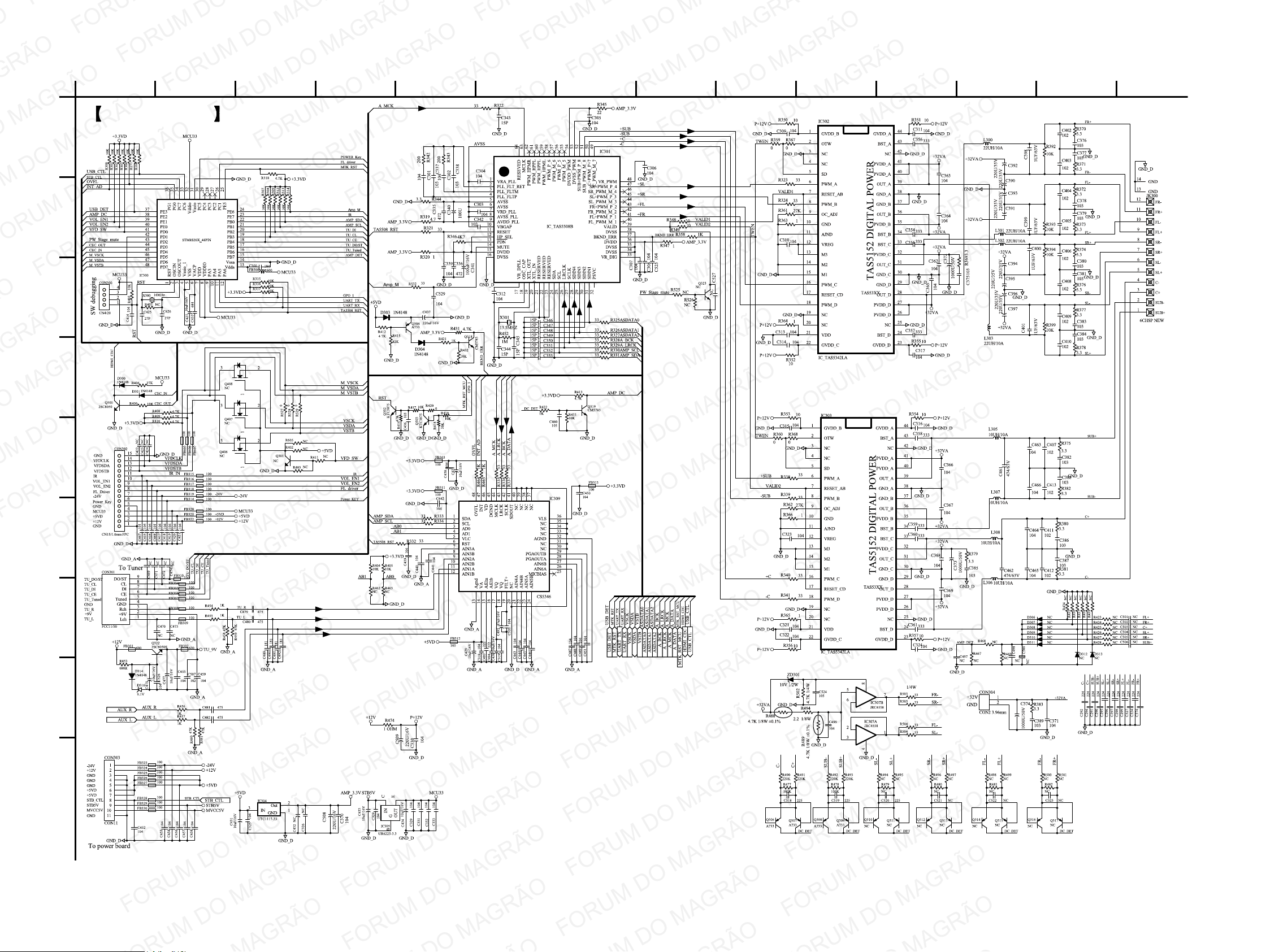
3-4. SCHEMATIC DIAGRAM – MAIN Section (1/2) –
A
B
C
D
1
234567891011121314
MAIN BOARD (1/2)
E
F
G
H
I
HBD-TZ135
1818
Page 19
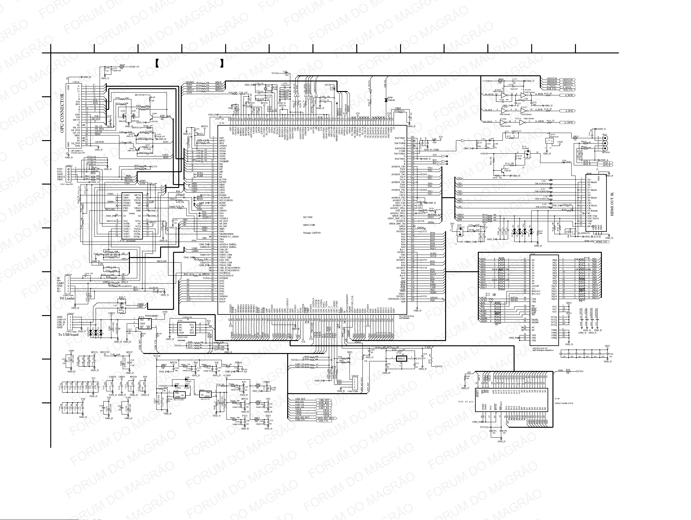
3-5. SCHEMATIC DIAGRAM – MAIN Section (2/2) –
HBD-TZ135
A
B
C
D
1
2345678910111213
MAIN BOARD (2/2)
E
F
G
H
I
HBD-TZ135
1919
Page 20
HBD-TZ135
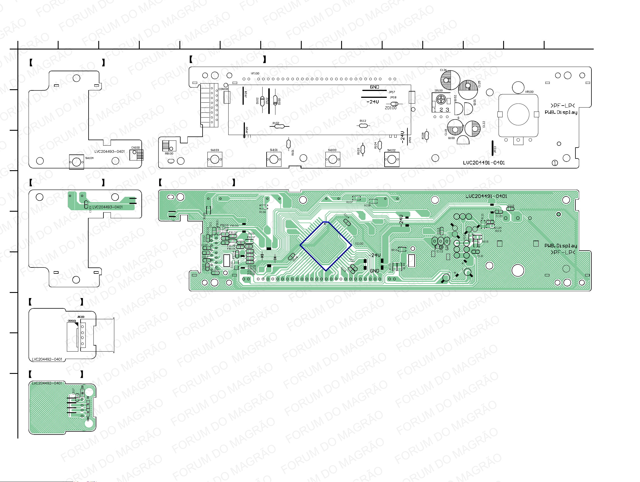
3-6. PRINTED WIRING BOARDS – DISPLAY Section –
A
B
C
D
1
234567891011121314
STANDBY BOARD (SIDE A)
STANDBY BOARD (SIDE B)
CONTROL BOARD (SIDE A)
CONTROL BOARD (SIDE B)
E
F
G
H
USB BOARD (SIDE A)
USB BOARD (SIDE B)
I
HBD-TZ135
2020
Page 21
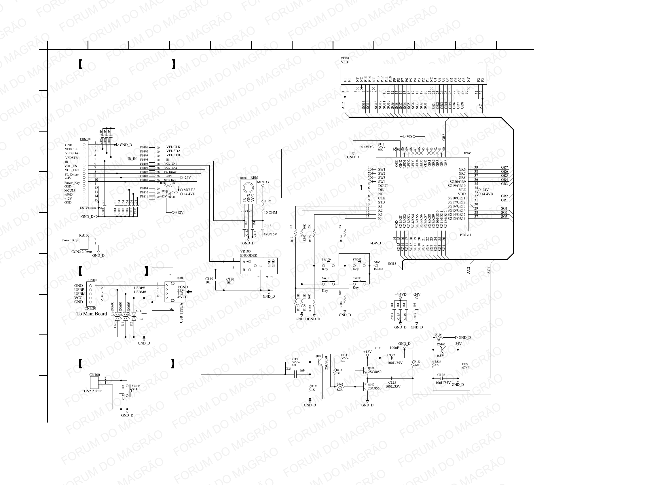
3-7. SCHEMATIC DIAGRAM – DISPLAY Section –
HBD-TZ135
A
B
C
D
1
23456789101112
CONTROL BOARD
E
F
G
H
I
USB BOARD
STANDBY BOARD
HBD-TZ135
2121
Page 22
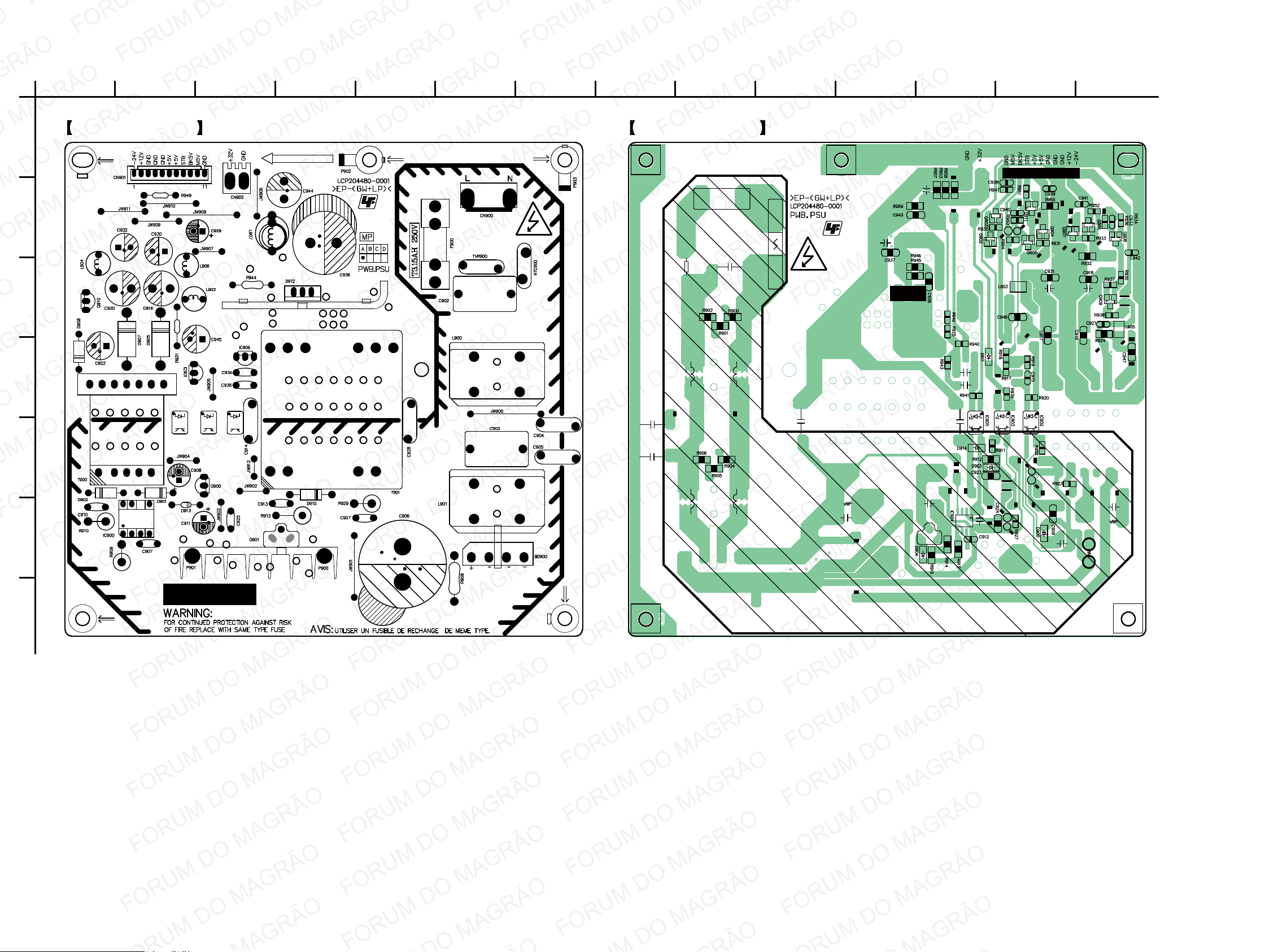
HBD-TZ135
3-8. PRINTED WIRING BOARD – POWER Section –
A
B
C
D
1
234567891011121314
POWER BOARD (SIDE A) POWER BOARD (SIDE B)
E
F
G
HBD-TZ135
2222
Page 23
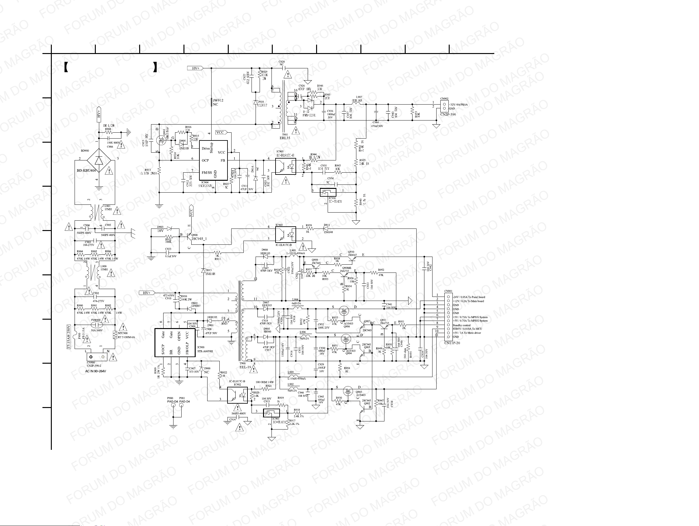
3-9. SCHEMATIC DIAGRAM – POWER Section –
HBD-TZ135
A
B
C
D
1
2345678910
POWER BOARD
E
F
G
H
I
HBD-TZ135
2323
Page 24
HBD-TZ135
Ver. 1.1
SECTION 4
EXPLODED VIEWS
MEMO
Note:
• Items marked “*” are not stocked since
they are seldom required for routine service. Some delay should be anticipated
when ordering these items.
• The mechanical parts with no reference
number in the exploded views are not supplied.
• Accessories are given in the last of the
electrical parts list.
• Abbreviation
AR : Argentina model
AUS : Australian model
BR : Brazilian model
CH : Chinese model
CND : Canadian model
E3 : 240V AC area in E model
E12 : 220 – 240V AC area in E model
E32 : 110 – 240V AC area in E model
MX : Mexican model
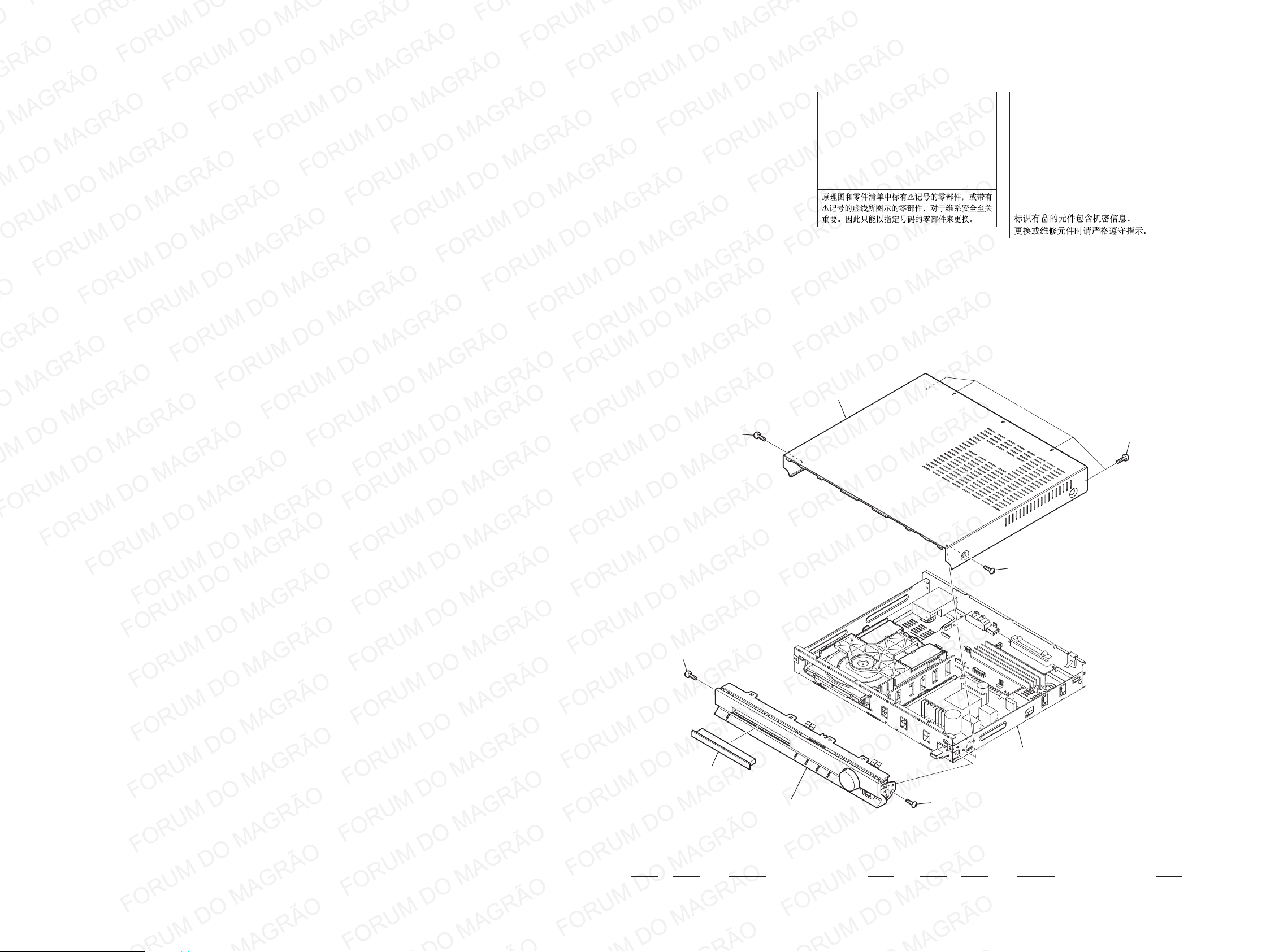
4-1. OVERALL SECTION
The components identifi ed by mark 0
or dotted line with mark 0 are critical for
safety.
Replace only with part number specifi ed.
Les composants identifi és par une marque
0 sont critiques pour la sécurité.
Ne les remplacer que par une pièce portant le numéro spécifi é.
PH : Philippines model
RU : Russian model
SAF : South African model
SP : Singapore model
TH : Thai model
4
The components identifi ed by mark 9 con-
tain confi dential information.
Strictly follow the instructions whenever the
components are repaired and/or replaced.
Les composants identifi és par la marque
9 contiennent des informations confi den-
tielles.
Suivre scrupuleusement les instructions
chaque fois qu’un composant est remplacé
et / ou réparé.
3
2
3
2
chassis section
HBD-TZ135
1
front cabinet section
Ref. No. Part No. Description Remark Ref. No. Part No. Description Remark
1 9-885-148-07 DOOR
2 9-885-144-64 +BVTT 3X6 BZN3
2
3 9-885-149-85 CASE SCREW
4 9-885-148-14 TOP COVER
2424
Page 25
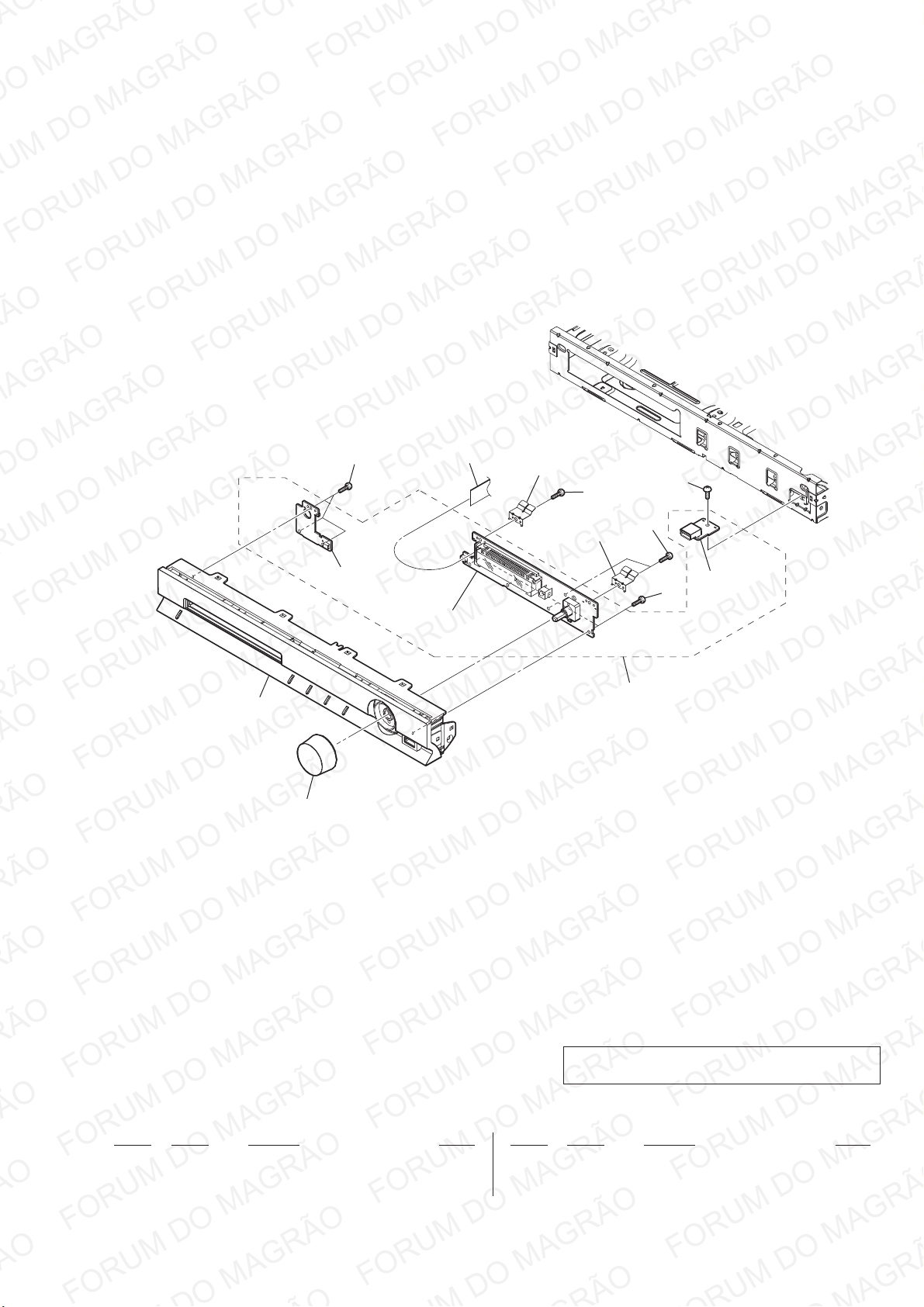
4-2. FRONT CABINET SECTION
HBD-TZ135
52
54
not supplied
(STANDBY board)
51
56
not supplied
(CONTROL board)
not supplied
not supplied
54
53
54
55
54
not supplied
(USB board)
Note: If the wire (fl at type) was replaced, fold it some as the
wire (fl at type) before replacement.
Ref. No. Part No. Description Remark Ref. No. Part No. Description Remark
51 9-885-148-08 VOLUME KNOB
52 9-885-149-84 FRONT CABINET ASSY (TZ135)
53 9-885-150-24 VFD PCB ASM
54 3-087-053-01 +BVTP2.6 (3CR)
55 9-885-144-66 +BVTT 3X7 CZN3 (POINT CIRCLE)
56 9-885-150-27 FLEXIBLE CABLE (15 CORE)
25
Page 26
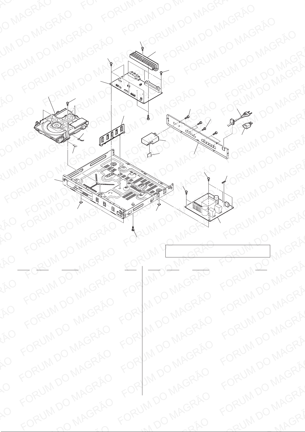
HBD-TZ135
Ver. 1.1
4-3. CHASSIS SECTION
DVD section
103
not supplied
102
not supplied
104
102
not supplied
107
#1
not supplied
102
108
109
105
not supplied
102
#2
102
106
105
#2
111
F900
101
101
110
not supplied
Note: If the wire (fl at type) was replaced, fold it some as the
wire (fl at type) before replacement.
Ref. No. Part No. Description Remark Ref. No. Part No. Description Remark
101 9-885-144-39 FOOT
102 9-885-144-66 +BVTT 3X7 CZN3 (POINT CIRCLE)
103 9-885-150-26 FLEXIBLE CABLE (5 CORE)
9 104 9-885-156-69 MAIN PCB ASSY (AEP)
9 104 9-885-156-70 MAIN PCB ASSY (UK)
9 104 9-885-156-71 MAIN PCB ASSY (RU)
9 104 9-885-156-72 MAIN PCB ASSY (PH)
9 104 9-885-156-73 MAIN PCB ASSY (MX)
9 104 9-885-156-74 MAIN PCB ASSY (E12)
9 104 9-885-156-75 MAIN PCB ASSY (E3)
9 104 9-885-156-76 MAIN PCB ASSY (TH)
9 104 9-885-156-77 MAIN PCB ASSY (E32)
9 104 9-885-156-78 MAIN PCB ASSY (CND)
9 104 9-885-156-79 MAIN PCB ASSY (SAF)
9 104 9-885-156-80 MAIN PCB ASSY (SP)
9 104 9-885-156-81 MAIN PCB ASSY (CH, BR)
9 104 9-885-156-82 MAIN PCB ASSY (AUS)
9 104 9-885-156-83 MAIN PCB ASSY (AR)
105 9-885-144-64 +BVTT 3X6 BZN3
0 106 9-885-150-12 AC CORD (AEP, E3, E12, E32, PH, RU, SAF, SP)
0 106 9-885-150-14 AC CORD (TH)
0 106 9-885-150-15 AC CORD (UK)
0 106 9-885-150-16 AC CORD (CH)
0 106 9-885-150-17 AC CORD (MX)
0 106 9-885-150-18 AC CORD (CND)
0 106 9-885-150-20 AC CORD (AR)
0 106 9-885-150-21 AC CORD (BR)
107 9-885-152-89 HEAT SINK SCREW
108 1-693-780-21 TUNER (FM)
(E3, E12, E32, AUS, AR, MX, PH, SP, TH)
108 1-693-781-21 TUNER (FM) (CND, BR)
108 1-693-788-21 TUNER (FM) (AEP, UK, CH, RU, SAF)
109 9-885-150-28 FLEXIBLE CABLE (9 CORE)
110 9-885-150-22 POWER PCB ASM (EXCEPT E12)
110 9-885-157-12 POWER PCB ASM (E12)
0 111 9-885-151-52 AC PLUG ADAPTOR FOR E12 (E3, E12)
0 111 9-885-157-95 AC PLUG ADAPTOR (E32, PH)
0 F900 9-885-150-11 FUSE (T3.15AH/250V)
#1 7-685-646-71 SCREW +BVTP 3X8 TYPE2 IT-3
#2 7-685-647-79 SCREW +P 3X10 TYPE2 NON-SLIT
0 106 9-885-150-13 AC CORD (AUS)
26
Page 27
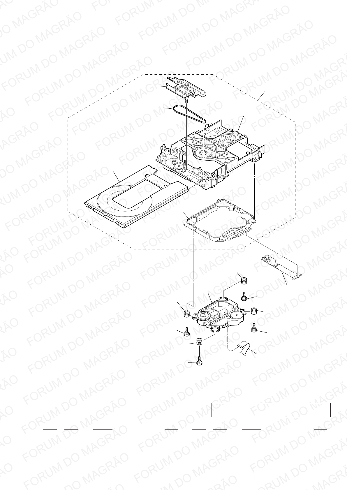
4-4. DVD MECHANISM DECK SECTION
HBD-TZ135
not supplied
not supplied
151
155
not supplied
not supplied
not supplied
not supplied
not supplied
153
not supplied
153
not supplied
152
153
154
153
Note: If the wire (fl at type) was replaced, fold it some as the
wire (fl at type) before replacement.
Ref. No. Part No. Description Remark Ref. No. Part No. Description Remark
0 151 A-1749-923-A CDM85 (MB) ASSY
0 152 8-820-321-05 OPTICAL PICK-UP BLOCK (KHM-313CAA/C2RP)
153 4-674-137-11 SCREW (PTP2X5)
154 9-885-150-25 FLEXIBLE CABLE (24 CORE)
155 3-088-371-01 BELT
27
Page 28
HBD-TZ135
REVISION HISTORY
Checking the version allows you to jump to the revised page.
Also, clicking the version at the top of the revised page allows you to jump to the next revised page.
Ver. Date Description of Revision
1.0 2011.02 New
1.1 2011.04 Addition of Canadian, E12, Australian, Chinese, Argentina, Brazilian and Singapore models.
 Loading...