

Page 1
DCR-HC17E/HC19E/HC21/HC21E/HC22E/
HC32/HC32E/HC33/HC33E
RMT-830/831
Ver 1.0 2005.01
Revision History
Revision History
Link
Link
Before starting adjustments
Before starting adjustments
Adjusting items when replacing main parts and boards
Adjusting items when replacing main parts and boards
(Non MS model)
(Non MS model)
Adjusting items when replacing main parts and boards
Adjusting items when replacing main parts and boards
(MS model)
(MS model)
CAMERA SECTION ADJUSTMENTS
CAMERA SECTION ADJUSTMENTS
PREPARATIONS BEFORE ADJUSTMENTS
PREPARATIONS BEFORE ADJUSTMENTS
INITIALIZATION OF 8, A, C, D, E, F, 1C, 1F
INITIALIZATION OF 8, A, C, D, E, F, 1C, 1F
PAGE DATA (Non MS model)
PAGE DATA (Non MS model)
INITIALIZATION OF 8, A, B, C, D, E, F, 18, 1A,
INITIALIZATION OF 8, A, B, C, D, E, F, 18, 1A,
1B, 1C, 1E, 1F PAGE DATA (MS model)
1B, 1C, 1E, 1F PAGE DATA (MS model)
SECTION 6
ADJUSTMENTS
ADJ
VIDEO SECTION ADJUSTMENTS
VIDEO SECTION ADJUSTMENTS
PREPARATIONS BEFORE ADJUSTMENTS
PREPARATIONS BEFORE ADJUSTMENTS
SYSTEM CONTROL SYSTEM ADJUSTMENTS
SYSTEM CONTROL SYSTEM ADJUSTMENTS
SERVO AND RF SYSTEM ADJUSTMENTS
SERVO AND RF SYSTEM ADJUSTMENTS
VIDEO SYSTEM ADJUSTMENTS
VIDEO SYSTEM ADJUSTMENTS
AUDIO SYSTEM ADJUSTMENTS (Non MS model)
AUDIO SYSTEM ADJUSTMENTS (Non MS model)
AUDIO SYSTEM ADJUSTMENTS (MS model)
AUDIO SYSTEM ADJUSTMENTS (MS model)
SERVICE MODE
SERVICE MODE
ADJUSTMENT REMOTE COMMANDER
ADJUSTMENT REMOTE COMMANDER
CAMERA SYSTEM ADJUSTMENTS
CAMERA SYSTEM ADJUSTMENTS
ELECTRONIC VIEWFINDER SYSTEM
ELECTRONIC VIEWFINDER SYSTEM
ADJUSTMENTS
ADJUSTMENTS
LCD SYSTEM ADJUSTMENTS
LCD SYSTEM ADJUSTMENTS
MECHANISM SECTION ADJUSTMENTS
MECHANISM SECTION ADJUSTMENTS
HOW TO ENTER RECORD MODE WITHOUT
HOW TO ENTER RECORD MODE WITHOUT
CASSETE
CASSETE
HOW TO ENTER PLAYBACK MODE WITHOUT
HOW TO ENTER PLAYBACK MODE WITHOUT
CASSETE
CASSETE
TAPE PATH ADJUSTMENT
TAPE PATH ADJUSTMENT
NON MS model: DCR-HC17E/HC19E/HC21/HC21E/HC22E
MS model: DCR-HC32/HC32E/HC33/HC33E
DATA PROCESS
DATA PROCESS
SERVICE MODE
SERVICE MODE
DCR-HC17E/HC19E/HC21/HC21E/HC22E/HC32/HC32E/HC33/HC33E
9-876-782-51
Sony EMCS Co.
2004L0500-1
© 2004.12
Published by DI Technical Support Section
Page 2

TABLE OF CONTENTS
Section Title Page Section Title Page
6. ADJUSTMENTS
1. Before Starting Adjustments ···········································6-1
1-1. Adjusting Items when Replacing Main Parts and
Boards (Non MS model) ·················································6-2
1-2. Adjusting Items when Replacing Main Parts and
Boards (MS model) ·························································6-4
6-1. Camera Section Adjustments···········································6-6
1-1. Preparations before Adjustments (CAMERA Section)···6-6
1-1-1.List of Service Tools ························································6-6
1-1-2.Preparations ····································································· 6-7
1-1-3.Precaution········································································6-8
1. Setting the Switch····························································6-8
2. Order of Adjustments ······················································6-8
3. Subjects ··········································································· 6-9
4. Preparing the Flash Adjustment Box·····························6-10
1-2. Initialization of 8, A, C, D, E, F, 1C, 1F Page Data
(Non MS model)····························································6-11
1-2-1.Initialization of A, D Page Data ····································6-11
1. Initializing of A, D Page Data ·······································6-11
2. Modification of A, D Page Data ····································6-11
3. A Page Table ··································································6-12
4. D Page Table ··································································6-12
1-2-2.Initialization of 8, C, 1C Page Data·······························6-13
1. Initializing of 8, C, 1C Page Data ·································6-13
2. Modification of 8, C, 1C Page Data ······························6-13
3. 8 Page Table ···································································6-14
4. C Page Table ··································································6-14
5. 1C Page Table ································································6-15
1-2-3.Initialization of E, F, 1F Page Data································6-16
1. Initializing of E, F, 1F Page Data ··································6-16
2. Modification of E, F, 1F Page Data ······························· 6-16
3. E Page Table ··································································6-17
4. F Page Table ··································································6-17
5. 1F Page Table ································································6-19
1-3. Initialization of 8, A, B, C, D, E, F, 18, 19,
1A, 1B, 1C, 1E, 1F Page Data (MS model) ··················6-20
1-3-1.Initialization of A, B, D, 1A, 1B Page Data ··················6-20
1. Initializing of A, B, D, 1A, 1B Page Data ·····················6-20
2. Modification of A, B, D, 1A, 1B Page Data··················6-20
3. A Page Table ··································································6-21
4. B Page Table ··································································6-21
5. D Page Table ··································································6-21
6. 1A Page Table ································································6-22
7. 1B Page Table ································································6-22
1-3-2.Initialization of 8, C, 18, 1C Page Data·························6-23
1. Initializing of 8, C, 18, 1C Page Data ···························6-23
2. Modification of 8, C, 18, 1C Page Data ························6-23
3. 8 Page Table ···································································6-24
4. C Page Table ··································································6-25
5. 18 Page Table ·································································6-26
6. 1C Page Table ································································6-27
1-3-3.Initialization of E, F, 19, 1E, 1F Page Data ···················6-28
1. Initializing of E, F, 19, 1E, 1F Page Data······················6-28
2. Modification of E, F, 19, 1E, 1F Page Data···················6-28
3. E Page Table ··································································6-29
4. F Page Table ··································································6-29
5. 19 Page Table ·································································6-31
6. 1E Page Table ································································6-31
7. 1F Page Table ································································6-32
1-4. Camera System Adjustments·········································6-33
1. 36MHz Origin Oscillation Adjustment
(VC-376 board (Non MS model))
(VC-377 board (MS model)) ········································ 6-33
2. Hall Adjustment·····························································6-34
3. Flange Back Adjustment
(Using the minipattern box or
flange back adjustment jig) ···········································6-35
4. Flange Back Adjustment
(Using the flange back adjustment chart and
subject more than 500 m away)·····································6-36
4-1. Flange Back Adjustment (1)··········································6-36
4-2. Flange Back Adjustment (2)··········································6-37
5. Flange Back Check························································6-37
6. Optical Axis Adjustment ··············································· 6-38
7. Picture Frame Setting
(Color reproduction adjustment frame) ·························6-39
8. Picture Frame Setting (Center frame) ···························6-40
9. F No. standard data input ··············································6-40
10. Mechanical Shutter Adjustment
(DCR-HC32/HC32E/HC33/HC33E) ····························6-41
11. Color Reproduction Adjustment····································6-42
12. Auto White Balance Standard Data Input ·····················6-43
13. LV Standard Data Input·················································6-43
14. Auto White Balance Adjustment ···································6-44
15. Auto White Balance Check ···········································6-45
16. MAX GAIN Adjustment ···············································6-46
17. Steadyshot Check ··························································6-47
1-5. Electronic Vie wfinder System Adjustments ··················6-48
1. EVF Automatic Adjustment (LB-109 board) ················6-48
1-6. LCD System Adjustments ·············································6-49
1. LCD Automatic Adjustment (PD-237 board)················6-49
2. V-COM Adjustment (PD-237 board) ····························6-50
3. Transmissive Mode White Balance Adjustment
(PD-237 board)······························································6-50
6-2. Mechanism Section Adjustments ··································6-51
2-1. How To Enter Record Mode Without Cassette··············6-51
2-2. How To Enter Playback Mode Without Cassette ··········6-51
2-3. Tape Path Adjustment····················································6-51
1. Preparation for Adjustment ···········································6-51
2. Procedure After Operations ···········································6-51
6-3. Video Section Adjustments ···········································6-52
3-1. Preparations Before Adjustments ·································· 6-52
3-1-1.Equipment Required······················································6-52
3-1-2.Precautions on Adjusting···············································6-52
3-1-3.Adjusting Connectors ···················································· 6-52
3-1-4.Connecting the Equipment ············································6-53
3-1-5.Alignment Tapes····························································6-54
3-1-6.Input/Output Level and Impedance·······························6-54
3-2. System Control System Adjustments ····························6-55
1. Initialization of 8, A, C, D, E, F,
1C,1F Page Data (Non MS model) ·······························6-55
2. Touch Panel Adjustment (Non MS model) ···················6-55
3. Initialization of 8, A, B, C, D, E, F, 18, 19,
1A, 1B, 1C, 1E, 1F Page Data (MS model) ··················6-56
4. Touch Panel Adjustment (MS model) ···························6-56
5. Node Unique ID No. Input ············································6-57
3-3. Servo and RF System Adjustments ·······························6-59
1. CAP FG Duty Adjustment
(VC-376 board (Non MS model))
(VC-377 board (MS model)) ·········································6-59
2. Switching Position Adjustment
(VC-376 board (Non MS model))
(VC-377 board (MS model)) ········································ 6-60
3. Error Rate Check
(VC-376 board (Non MS model))
(VC-377 board (MS model)) ·········································6-61
3-1. Preparations Before Adjustments ·································· 6-61
3-2. Error Rate Check ···························································6-61
DCR-HC17E/HC19E/HC21/HC21E/HC22E/HC32/HC32E/HC33/HC33E
— 2 —
Page 3

Section Title Page
3-4. Video System Adjustments ············································6-62
1. S VIDEO OUT Y Level Adjustment
(VC-376 board (Non MS model))
(VC-377 board (MS model)) ·········································6-62
2. S VIDEO OUT Chroma Level Adjustment
(VC-376 board (Non MS model))
(VC-377 board (MS model)) ·········································6-63
3. VIDEO OUT Level Check
(VC-376 board (Non MS model))
(VC-377 board (MS model)) ·········································6-64
3-5. Audio System Adjustments (Non MS model)···············6-65
1. Playback Level Check ···················································6-65
2. Overall Level Characteristics Check ·····························6-65
3. Overall Distortion Check···············································6-66
4. Overall Noise Level Check············································6-66
5. Overall Separation Check··············································6-66
3-6. Audio System Adjustments (MS model)·······················6-67
1. Playback Level Check ···················································6-67
2. Overall Level Characteristics Check ·····························6-67
3. Overall Distortion Check···············································6-68
4. Overall Noise Level Check············································6-68
5. Overall Separation Check··············································6-68
6-4. Service Mode·································································6-69
4-1. Adjustment Remote Commander ··································6-69
1. Using the Adjustment Remote Commander··················6-69
2. Precautions Upon Using the Adjustment
Remote Commander······················································6-69
4-2. Data Process ··································································6-70
4-3. Service Mode·································································6-71
1. Setting the Test Mode ···················································· 6-71
1-1. Setting the Test Mode (Non MS model)························6-71
1-2. Setting the Test Mode (MS model) ······························· 6-71
2. Emergence Memory Address (Non MS model) ············6-71
2-1. Emergency Memory Address (Camera section)············6-71
2-2. EMG Code (Emergency Code) ·····································6-71
3. Emergence Memory Address (MS model) ····················6-72
3-1. Emergency Memory Address (Camera section)············6-72
3-2. EMG Code (Emergency Code) ·····································6-72
4. Emergence Memory Address (Mechanism section)······6-72
4-1. EMG Code (Emergency Code) ·····································6-73
4-2. MSW Code ····································································6-74
5. Bit V alue Discrimination ···············································6-75
6. Jack Check (Non MS model) ········································6-75
6-1. Jack Check (1) (Handycam station) (DCR-HC22E) ·····6-75
6-2. Jack Check (2) ·······························································6-75
7. Jack Check (MS model) ················································6-76
7-1. Jack Check (1) (Handycam station) ······························6-76
7-2. Jack Check (2) ·······························································6-76
8. Switch Check (Non MS model) ····································6-76
8-1. Switch Check (1) ···························································6-76
8-2. Switch Check (2) ···························································6-76
8-3. Switch Check (3) ···························································6-77
8-4. Switch Check (4) ···························································6-77
9. Switch Check (MS model) ············································6-78
9-1. Switch Check (1) ···························································6-78
9-2. Switch Check (2) ···························································6-78
9-3. Switch Check (3) ···························································6-78
9-4. Switch Check (4) ···························································6-79
10. LED, IR Light Check (Non MS model) ························6-80
11. LED, IR Light Check (MS model) ································6-80
12. Record of Use Check (1) ···············································6-80
13. Record of Use Check (2) (Non MS model)···················6-81
14. Record of Use Check (3) (MS model)···························6-82
15. Record of Use Check (4) ···············································6-82
16. Record of Self-diagnosis Check ····································6-83
* The camera optical axis frame is shown on page 6-84.
The camera color reproduction frame is shown on page
6-85.
Note : Non MS model: DCR-HC17E/HC19E/HC21/HC21E/
HC22E
MS model: DCR-HC32/HC32E/HC33/HC33E
DCR-HC17E/HC19E/HC21/HC21E/HC22E/HC32/HC32E/HC33/HC33E
— 3 —
Page 4

1. Before starting adjustments
(Machine before starting repair)
(Machine after a board is replaced)
PC PC
Save the EVR data
to a personal computer.
Download the saved
data to a machine.
EVR Data Re-writing Procedure When Replacing Board
The data that is stored in the repair board, is not necessarily correct.
Perform either procedure 1 or procedure 2 or procedure 3 when replacing board.
Procedure 1
Save the EVR data of the machine in which a board is going to be replaced. Download the saved data after a
board is replaced.
SECTION 6
ADJUSTMENTS
Procedure 2
Remove the EEPROM from the board of the machine that is going to be repaired. Install the removed
EEPROM to the replaced board.
Remove the EEPROM and install it.
(Former board)
(New board)
Procedure 3
When the data cannot be saved due to defective EEPROM, or when the EEPROM cannot be removed or
installed, save the data from the same model of the same destination, and download it.
(Machine to be repaired) (Machine to be repaired)
PC
Download the data.
(The same model of the same destination)
After the EVR data is saved and downloaded, chec k the
respective items of the EVR data.
(Refer to page 6-3 or 6-5 for the items to be checked)
DCR-HC17E/HC19E/HC21/HC21E/HC22E/HC32/HC32E/HC33/HC33E
Save the data.
6-1
Page 5
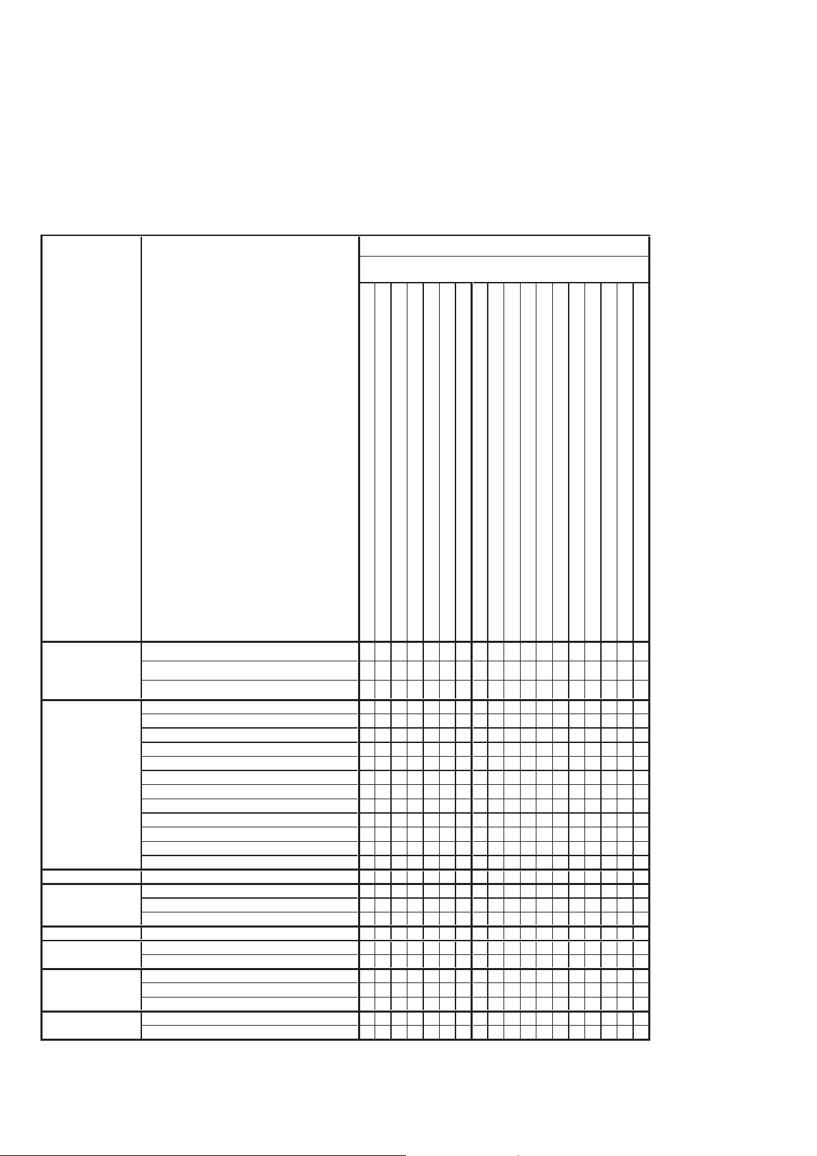
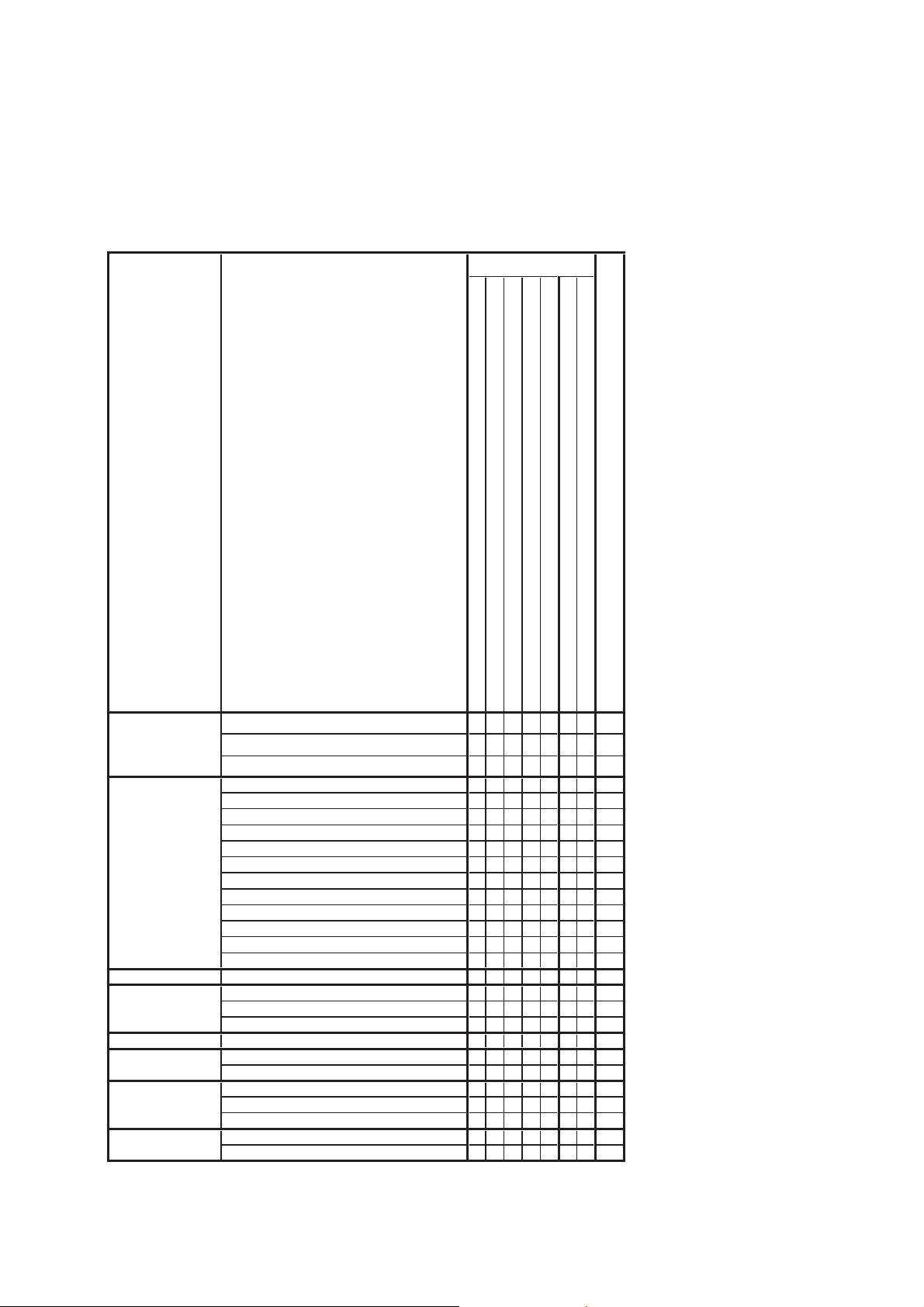
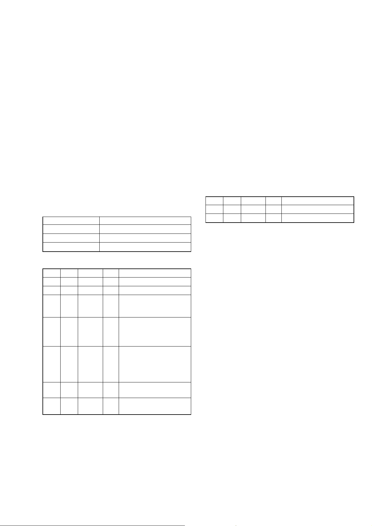
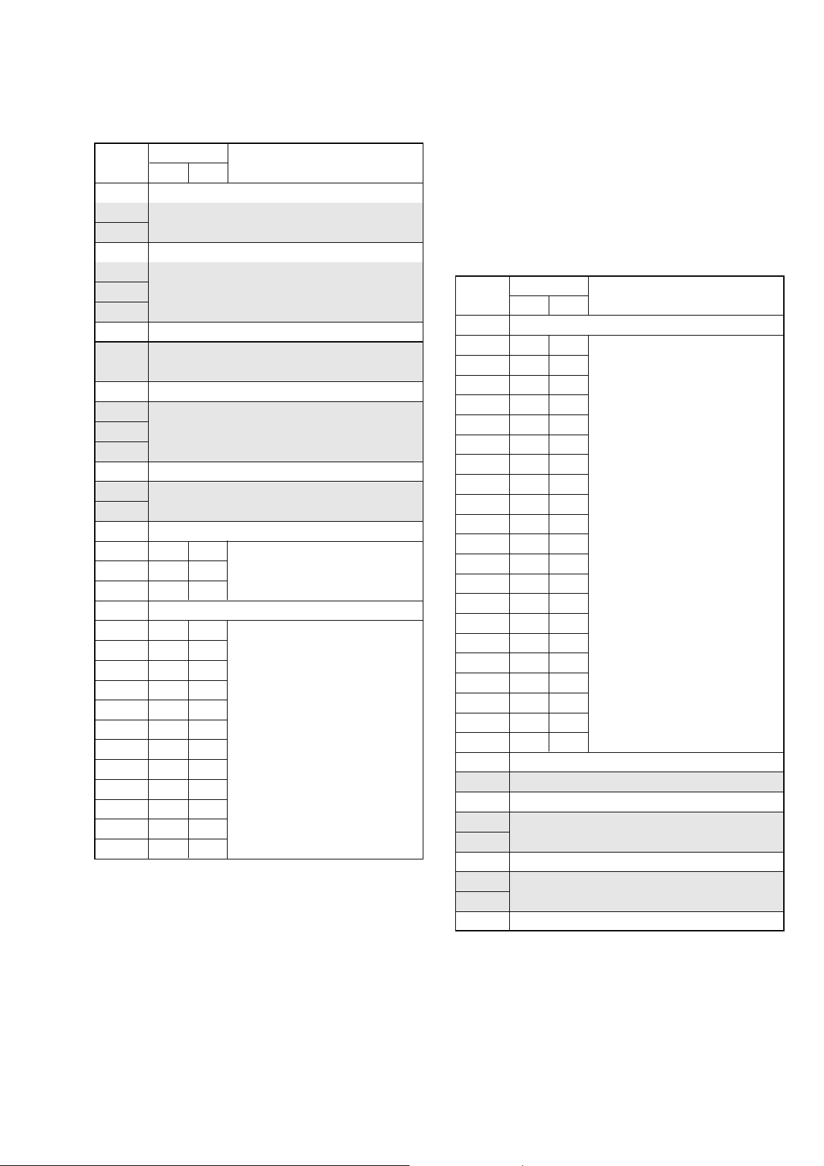
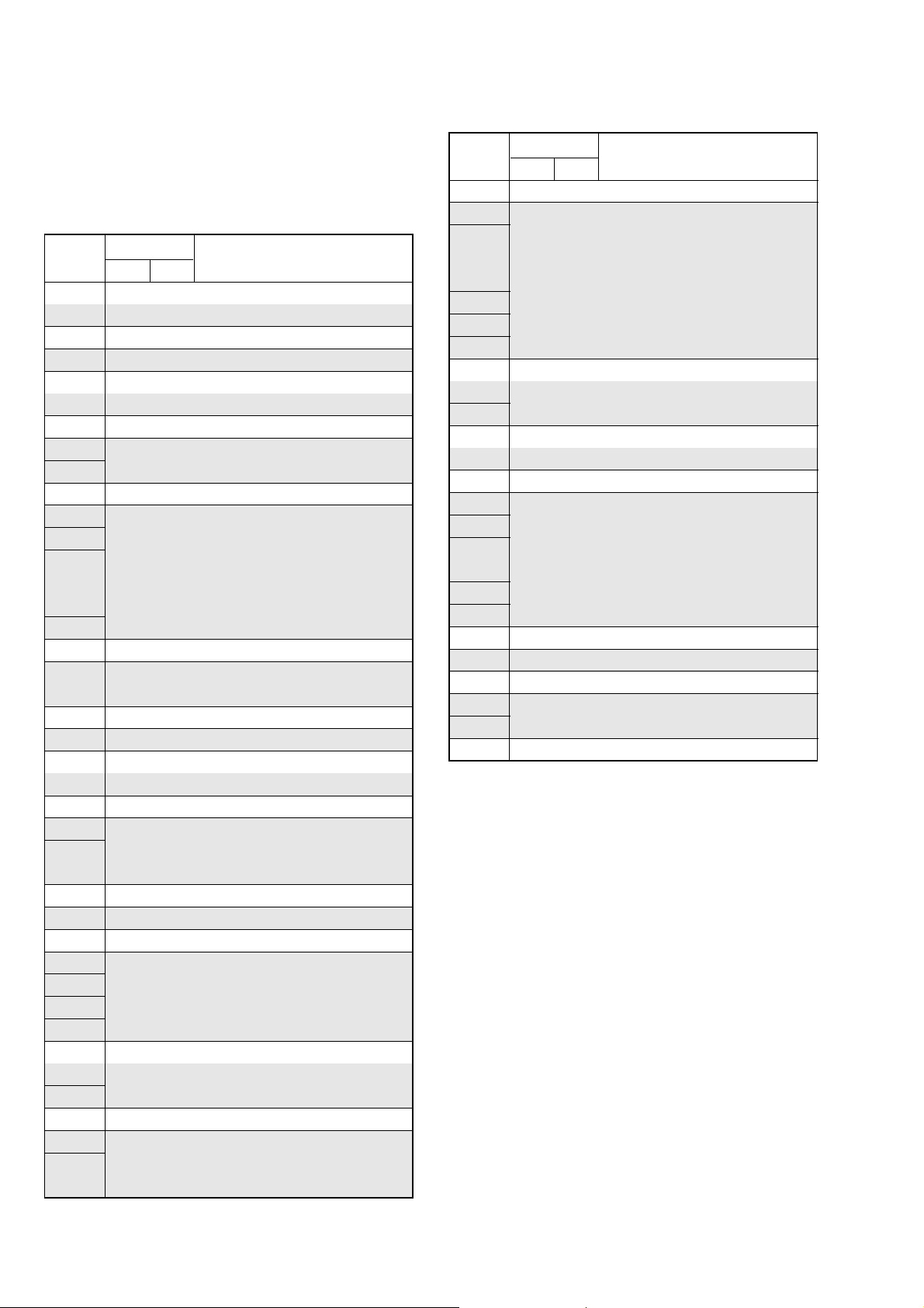
1-1. Adjusting items when replacing main parts and boards (Non MS model)
• Adjusting items when replacing main parts
When replacing main parts, adjust the items indicated by z in the following table.
Note 1: When replacing the drum assy or the mechanism deck, reset the data of page: 7, address: A8 to AB to “00”. (Refer to “Record of
Use check” of “6-4. SERVICE MODE”)
Note 2: Non MS model: DCR-HC17E/HC19E/HC21/HC21E/HC22E
Note 3: DCR-HC32/HC32E/HC33/HC33E model only.
Replaced part
Adjustment Section Adjustment
Block replacement Mounted part replacement
(LCD panel, Touch panel)
(Back light LED)
(LCD panel)
(Drum assembly) (Note 1)
(CCD imager)
(Back light (EVF))
(LCD drive)
(PITCH, YAW sensor)
(Timing generator)
(S/H, AGC, A/D converter)
(DV signal process)
Initialization of 8,
A, C, D, E, F, 1C,
1F page data
Initialization of A, D page data
Initialization of 8, C, 1C page data
Initialization of E, F, 1F page data
Camera 36MHz origin oscillation adj.
HALL adj.
Flange back adj.
Optical axis adj.
F No. standard data input
Mechanical shutter adj. (Note 3)
Color reproduction adj.
Auto white balance standard data input
LV standard data input
Auto white balance adj.
MAX GAIN adj.
Steadyshot check
EVF EVF automatic adj.
LCD LCD automatic adj.
V-COM adj.
Transmissive mode white balance adj.
Mechanism Tape path adj.
System control Touch panel adj.
Node uniqe ID No. input
Servo, RF CAP FG duty adj.
Switching position adj.
Error rate check
Video S VIDEO OUT Y level adj.
S VIDEO OUT chroma level adj.
Lens device
LCD block LCD901
LCD block D901
EVF block LCD902
Mechanism deck (Note 1)
Mechanism deck M901
Mechanism deck MD block
CD-533 board IC101
LB-109 board D303
PD-237 board IC602
SI-042 board SE601, 602
VC-376 board IC3001, X3001
VC-376 board IC3002
VC-376 board IC6001
z
z
zz
zz
zz
z
zz
zz
zz
zz
zz
z
zzz
zz
zz
zz z
zzz
z
zz
zzz
zzz z
z
z
DCR-HC17E/HC19E/HC21/HC21E/HC22E/HC32/HC32E/HC33/HC33E
Table 6-1-1 (1)
6-2
Page 6
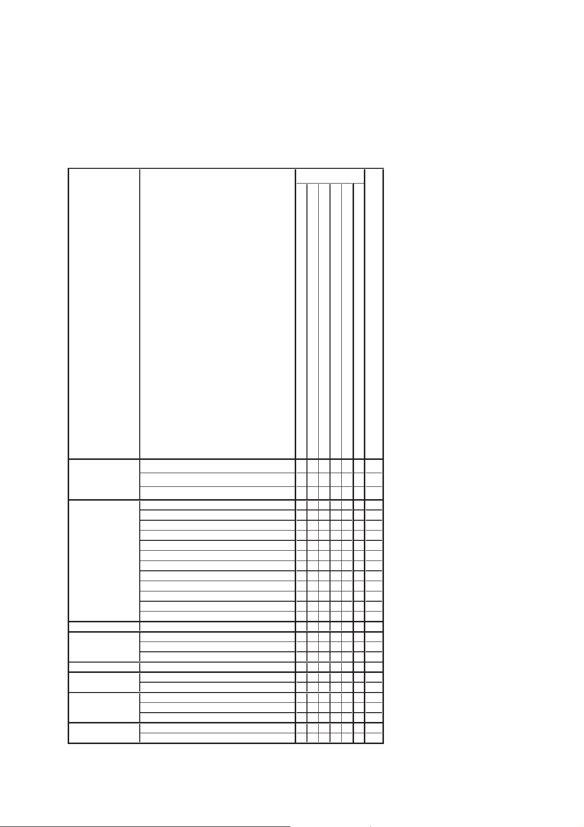
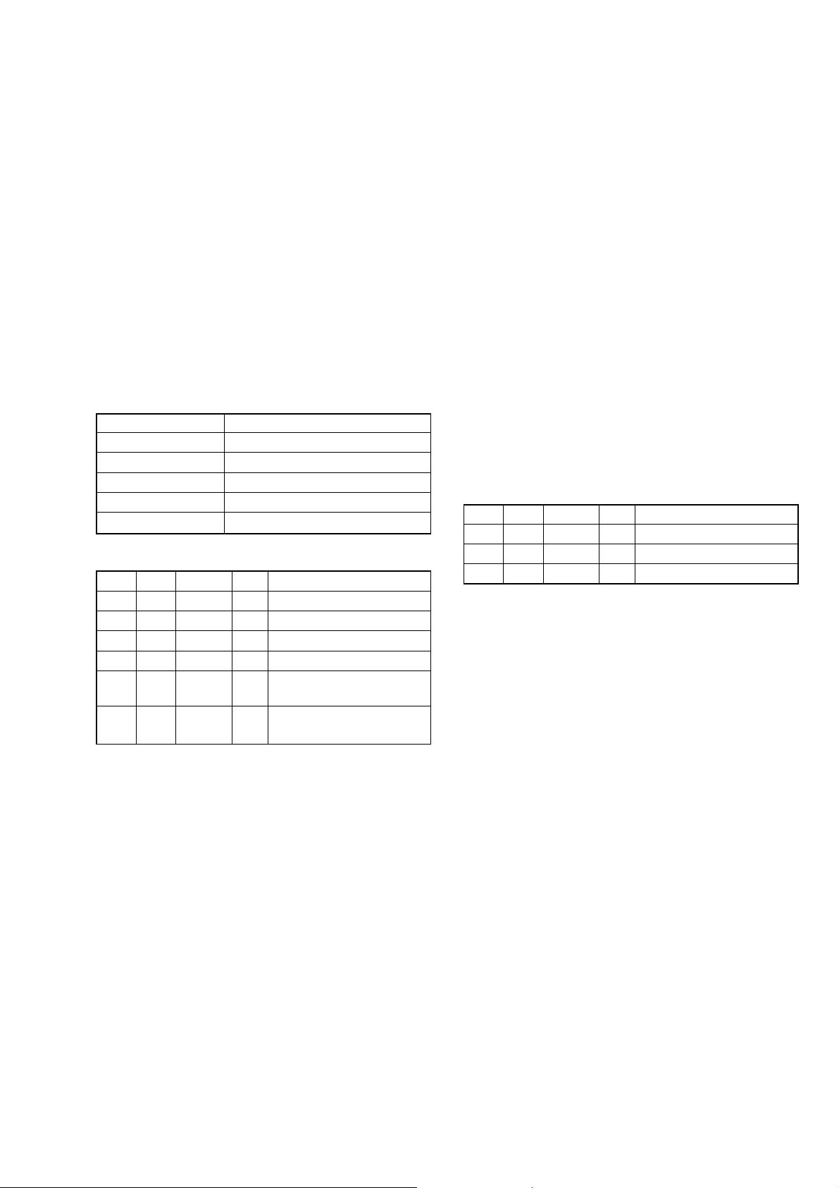
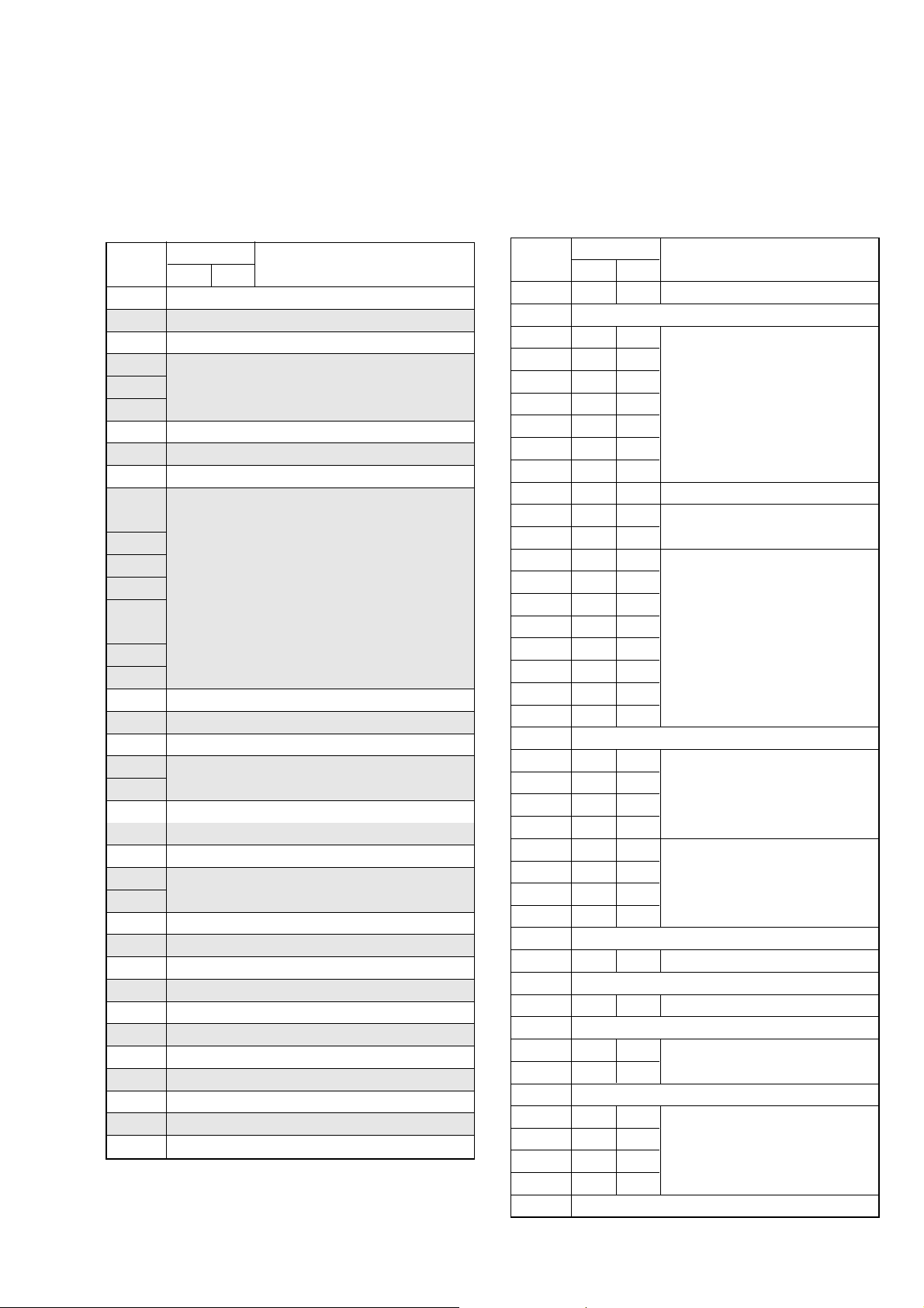
• Adjusting items when replacing a board or EEPROM
When replacing a board or EEPROM, adjust the items indicated by z in the following table.
Replaced part
Adjustment Section Adjustment
Initialization of 8,
A, C, D, E, F, 1C,
1F page data
Initialization of A, D page data
Initialization of 8, C, 1C page data
Initialization of E, F, 1F page data
Camera 36MHz origin oscillation adj.
HALL adj.
Flange back adj.
Optical axis adj.
F No.standard data input
Mechanical shutter adj. (Note 3)
Color reproduction adj.
Auto white balance standard data input
LV standard data input
Auto white balance adj.
MAX GAIN adj.
Steadyshot check
EVF EVF automatic adj.
LCD LCD automatic adj.
V-COM adj.
Transmissive mode white balance adj.
Mechanism Tape path adj.
System control Touch panel adj.
Node uniqe ID No. input
Servo, RF CAP FG duty adj.
Switching position adj.
Error rate check
Video S VIDEO OUT Y level adj.
S VIDEO OUT chroma level adj.
(COMPLETE)
(COMPLETE)
(COMPLETE)
(COMPLETE)
(COMPLETE)
(EEP ROM)
RadarWRadarWRadarW
CD-533 board
LB-109 board
PD-237 board
SI-042 board
VC-376 board
VC-376 board IC8602
Supporting
zz
zz
zz
zz
zz z
zzzz
zzz
zzzz
zz z
zzz
zzzz
zzzz
zzzz
zzzz
zzz z
zz z
zzzz
zzz
zzz
zz
zz
zz z
zz z
zz z
zz
zz
Table 6-1-1 (2)
DCR-HC17E/HC19E/HC21/HC21E/HC22E/HC32/HC32E/HC33/HC33E
6-3
Page 7
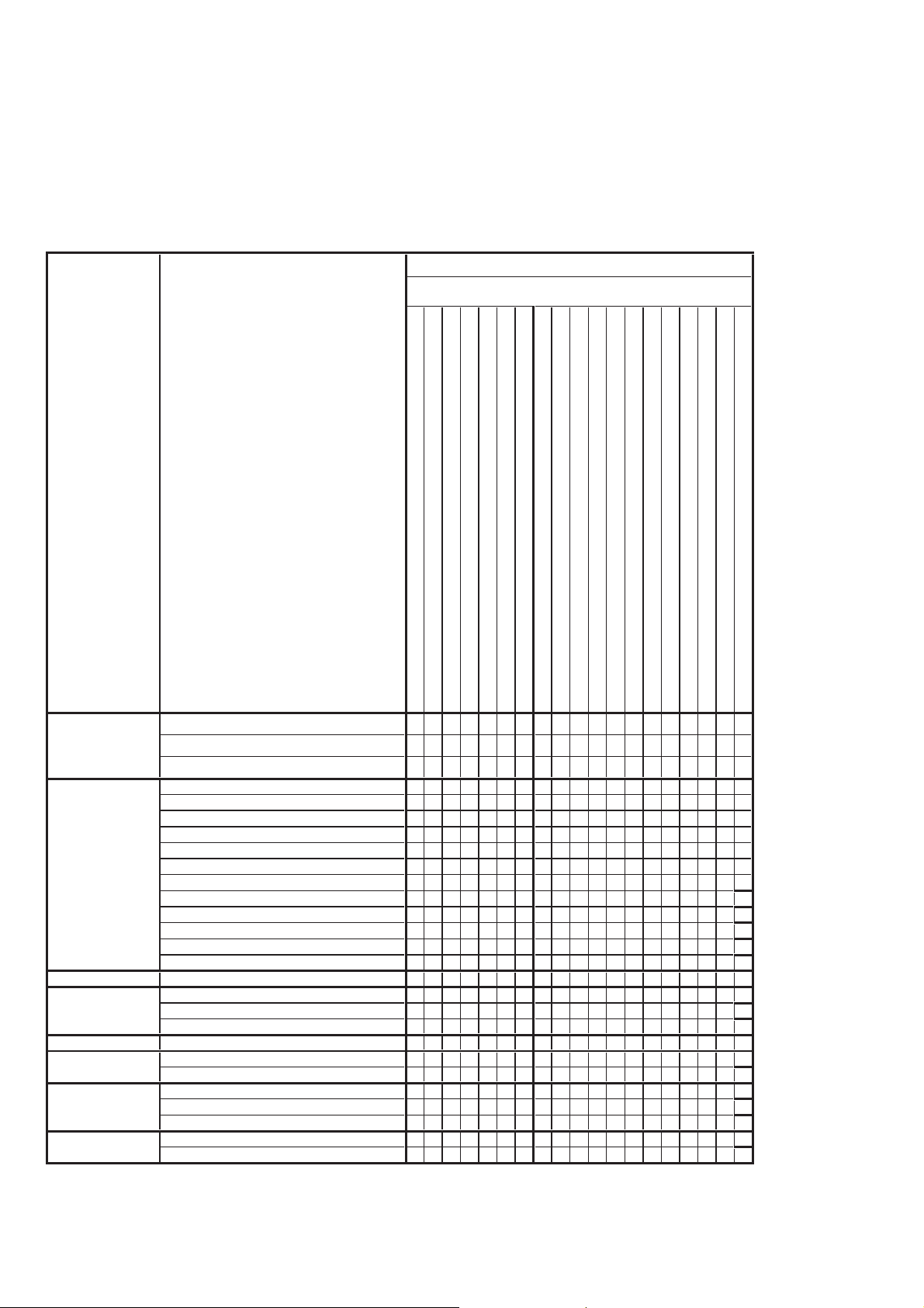
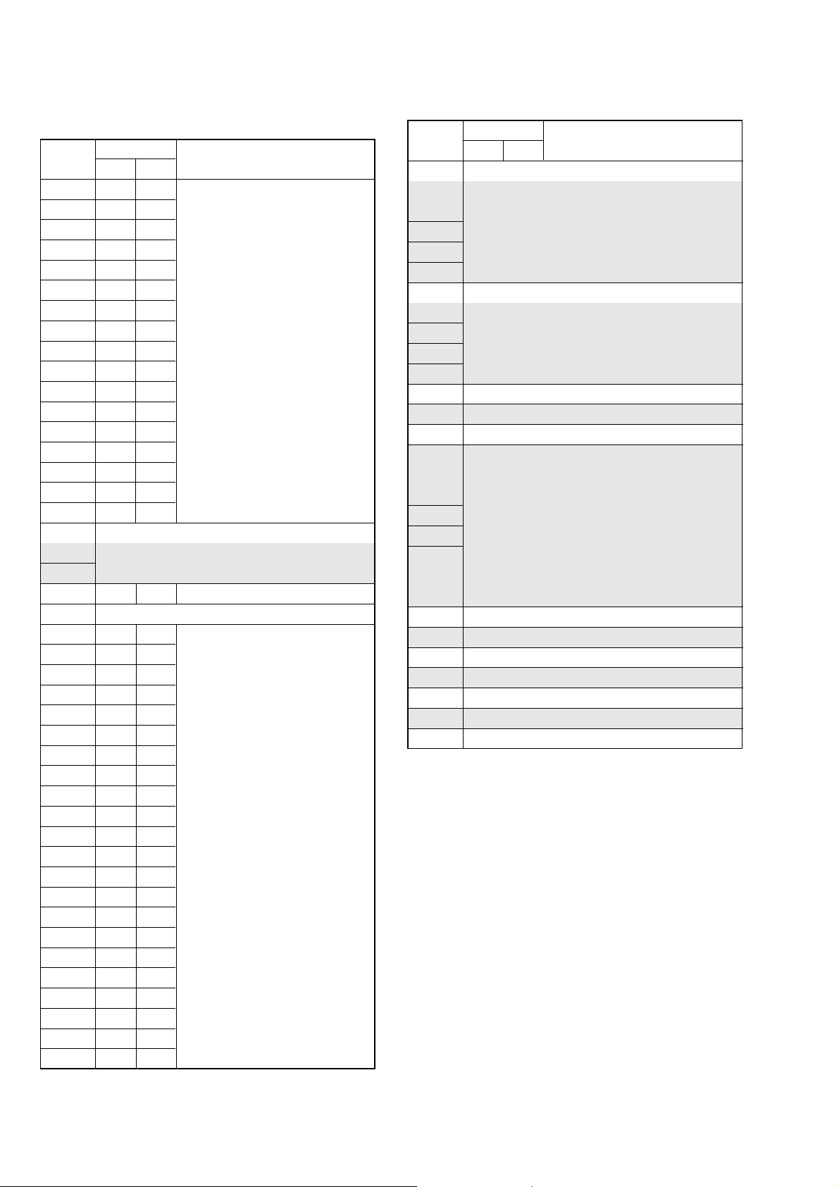
1-2. Adjusting items when replacing main parts and boards (MS model)
• Adjusting items when replacing main parts
When replacing main parts, adjust the items indicated by z in the following table.
Note 1: When replacing the drum assy or the mechanism deck, reset the data of page: 7, address: A8 to AB to “00”. (Refer to “Record of
Use check” of “6-4. SERVICE MODE”)
Note 2: MS model: DCR-HC32/HC32E/HC33/HC33E
Replaced part
Block replacement Mounted part replacement
Adjustment Section Adjustment
(LCD panel, Touch panel)
(Back light LED)
(LCD panel)
(Drum assembly) (Note 1)
(CCD imager)
(Back light (EVF))
(LCD drive)
(PITCH, YAW sensor)
(Timing generator)
(S/H, AGC, A/D converter)
(Video/Audio DSP, D/A converter etc)
(DV signal process)
(REC/PB AMP)
(Video IN/OUT)
(HI/DS control)
(EVF drive)
Initialization of 8,
A, B, C, D, E, F, 18,
19, 1A, 1B, 1C, 1E,
1F page data
Initialization of A, B, D, 1A, 1B page data
Initialization of 8, C, 18, 1C page data
Initialization of E, F, 19, 1E, 1F page data
Camera 36MHz origin oscillation adj.
HALL adj.
Flange back adj.
Optical axis adj.
F No. standard data input
Mechanical shutter adj.
Color reproduction adj.
Auto white balance standard data input
LV standard data input
Auto white balance adj.
MAX GAIN adj.
Steadyshot check
EVF EVF automatic adj.
LCD LCD automatic adj.
V-COM adj.
Transmissive mode white balance adj.
Mechanism Tape path adj.
System control Touch panel adj.
Node uniqe ID No. input
Servo, RF CAP FG duty adj.
Switching position adj.
Error rate check
Video S VIDEO OUT Y level adj.
S VIDEO OUT chroma level adj.
Lens device
LCD block LCD901
LCD block D901
EVF block LCD902
Mechanism deck (Note 1)
Mechanism deck M901
Mechanism deck MD block
CD-533 board IC101
LB-109 board D303
PD-237 board IC602
SI-042 board SE601, 602
VC-377 board IC3101, X3101
VC-377 board IC3102
VC-377 board IC4001
zz
z
zz
zz
zz
z
zz
zz
zz
zz
zz
z
zzz
zz
zz
zz z
zzz
z
zz
zzz
zzz zz
zz
zz
VC-377 board IC4201
VC-377 board IC4301
VC-377 board IC4401
VC-377 board IC5102
VC-377 board IC7001
DCR-HC17E/HC19E/HC21/HC21E/HC22E/HC32/HC32E/HC33/HC33E
Table 6-1-2 (1)
6-4
Page 8
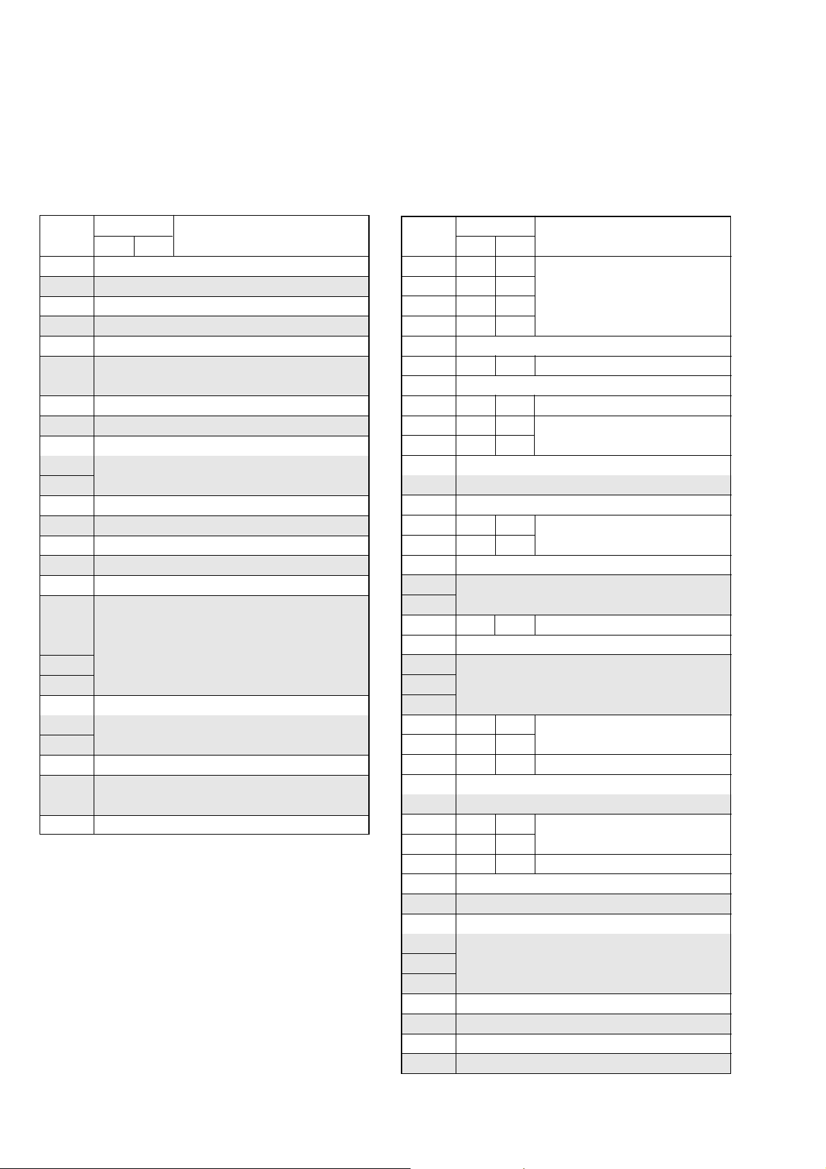
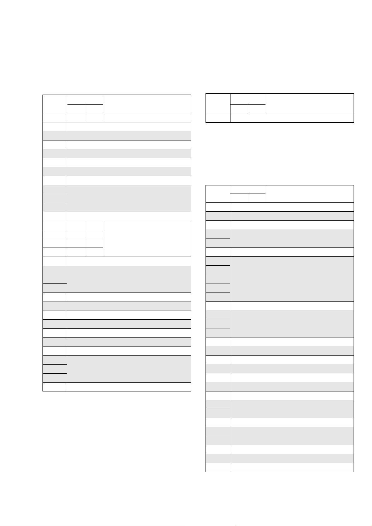
• Adjusting items when replacing a board or EEPROM
When replacing a board or EEPROM, adjust the items indicated by z in the following table.
Adjustment Section Adjustment
Initialization of 8,
A, B, C, D, E, F, 18,
19, 1A, 1B, 1C, 1E,
1F page data
Initialization of A, B, D, 1A, 1B page data
Initialization of 8, C, 18, 1C page data
Initialization of E, F, 19, 1E, 1F page data
Camera 36MHz origin oscillation adj.
HALL adj.
Flange back adj.
Optical axis adj.
F No.standard data input
Mechanical shutter adj.
Color reproduction adj.
Auto white balance standard data input
LV standard data input
Auto white balance adj.
MAX GAIN adj.
Steadyshot check
EVF EVF automatic adj.
LCD LCD automatic adj.
V-COM adj.
Transmissive mode white balance adj.
Mechanism Tape path adj.
System control Touch panel adj.
Node uniqe ID No. input
Servo, RF CAP FG duty adj.
Switching position adj.
Error rate check
Video S VIDEO OUT Y level adj.
S VIDEO OUT chroma level adj.
Replaced part
(COMPLETE)
(COMPLETE)
(COMPLETE)
(COMPLETE)
(COMPLETE)
(EEP ROM)
(EEP ROM)
Note 3: IC5202 (Flash memory) on
RadarWRadarWRadarW
CD-533 board
LB-109 board
PD-237 board
SI-042 board
VC-377 board
VC-377 board IC5302
VC-377 board IC5101
Supporting
zz
zz
zz
zz
zz z
zzzz
zzz
zzzz
zz z
zzzz
zzzz
zzzz
zzzz
zzzz
zzz z
zzzz
zzz z
zzz
zzz
zz
zz
zz z
zz z
zz z
zz
zz
the VC-377 board cannot be
replaced.
Table 6-1-2 (2)
DCR-HC17E/HC19E/HC21/HC21E/HC22E/HC32/HC32E/HC33/HC33E
6-5
Page 9
6-1. CAMERA SECTION A DJUSTMENTS
1-1. PREPARATIONS BEFORE ADJUSTMENTS (CAMERA SECTION)
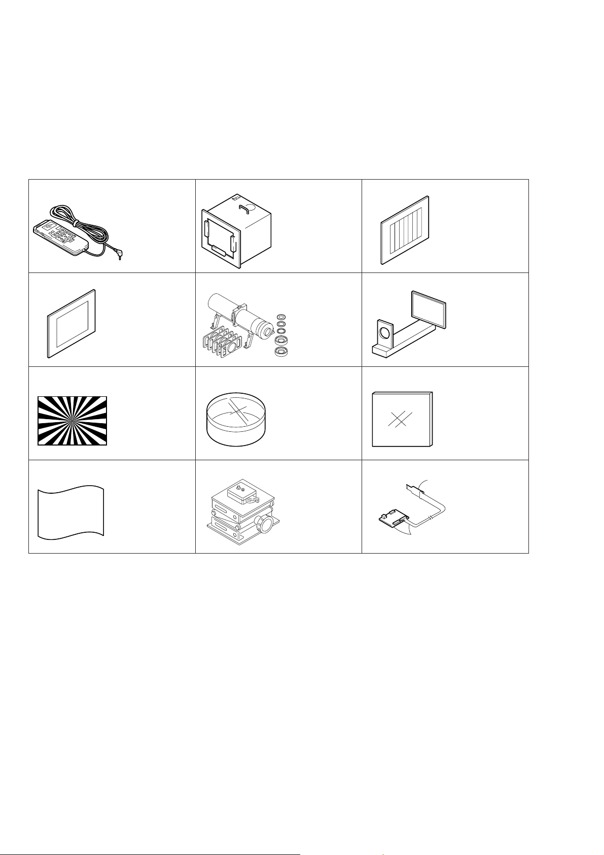
1-1-1. List of Service Tools
• Oscilloscope • Color monitor • Vectorscope
• AC power adapter • Frequency counter
J-1
J-4
J-7
J-10
Adjustment remote
commander
J-6082-053-B
Clear chart
For PTB-450:
J-6080-621-A
For PTB-1450:
J-6082-560-A
Siemens star chart
J-6080-875-A
Back ground paper
J-2501-130-A
J-2
J-3
Pattern box PTB-450
J-6082-200-A
or
Small pattern box
PTB-1450
J-6082-557-A
J-5
J-6
Minipattern box
J-6082-353-B
J-8
J-9
Filter for color
temperature correction
(C14)
J-6080-058-A
J-11 J-12
Camera table
J-6082-384-A
Color bar chart
For PTB-450:
J-6020-250-A
For PTB-1450:
J-6082-559-A
Flange back
adjustment jig
J-6082-563-A
ND filter 1.0
J-6080-808-A
ND filter 0.4
J-6080-806-A
ND filter 0.1
J-6080-807-A
A
A: CPC-15
J-6082-564-A
B: I/F unit for
LANC control
B
J-6082-521-A
DCR-HC17E/HC19E/HC21/HC21E/HC22E/HC32/HC32E/HC33/HC33E
Fig. 6-1-1
6-6
Page 10
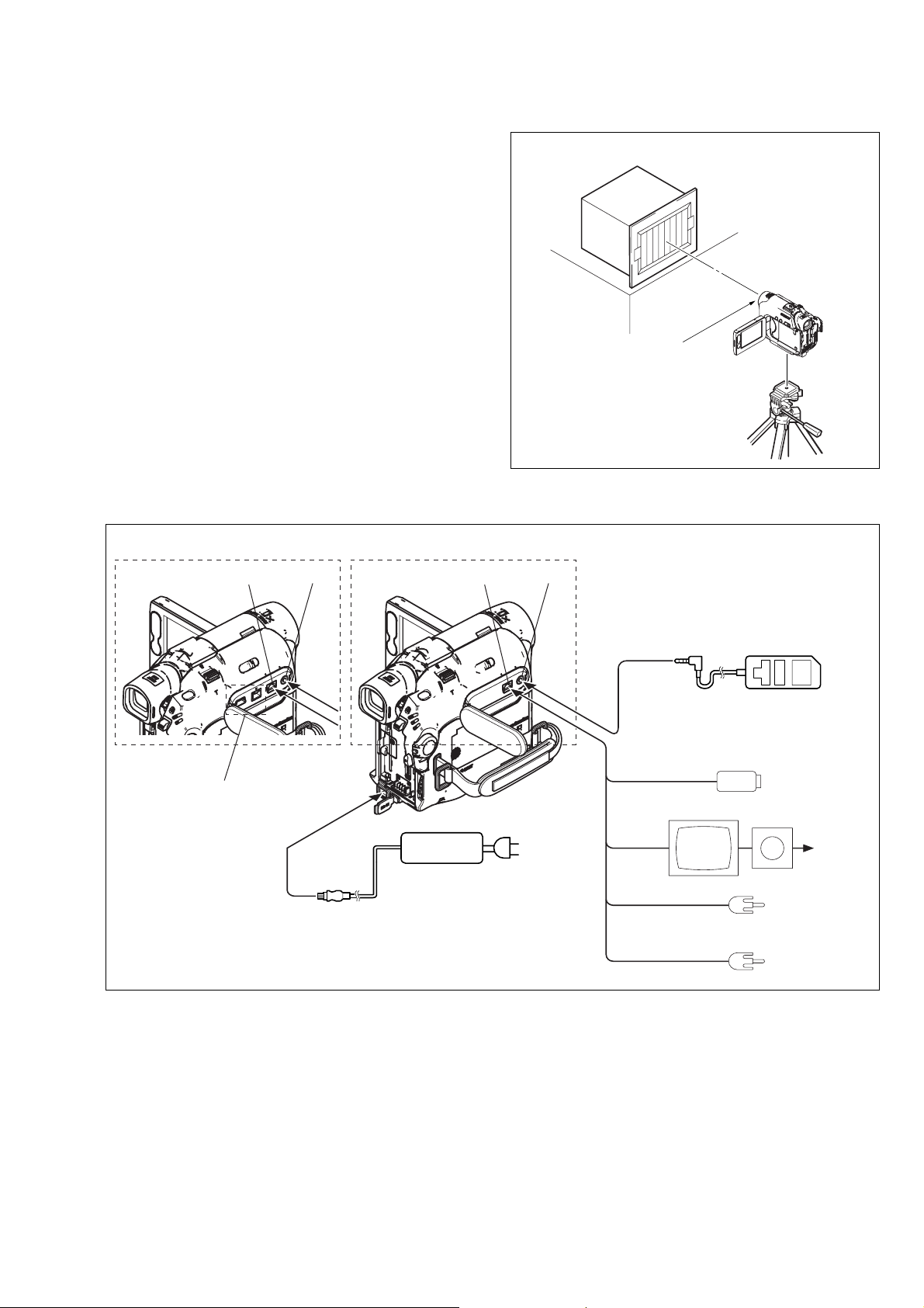
1-1-2. Preparations
Note: Before perform the adjustment, check that the data of page:
0, address: 10 is “00”.
If not, select page: 0, address: 10, and set data “00”.
1) Connect the equipment for adjustments according to Fig. 6-1-3.
Pattern box
Front of the lens
L = 1m (PTB-450)
L = 40cm (PTB-1450)
Fig. 6-1-2
L
(Non MS model)
A/V OUT jack
Except DCR-HC22E
Note: Non MS model: DCR-HC17E/HC19E/HC21/HC21E/HC22E
MS model: DCR-HC32/HC32E/HC33/HC33E
LANC jack
To DC IN jack
(MS model)
AC adaptor
A/V jack
LANC jack
AC IN
S Video
(Black)
Video
(yellow)
Audio L
(White)
Audio R
(Red)
Adjustment remote commander
Color monitor
(RM-95)
Vectorscope
Terminated
75 Ω
DCR-HC17E/HC19E/HC21/HC21E/HC22E/HC32/HC32E/HC33/HC33E
Fig. 6-1-3
6-7
Page 11
1-1-3. Precaution
1. Setting the Switch
Unless otherwise specified, set the switches as follows and perform adjustments without loading cassette.
Note : Non MS model: DCR-HC17E/HC19E/HC21/HC21E/HC22E
MS model: DCR-HC32/HC32E/HC33/HC33E
(Non MS model)
1. POWER switch (SS10300 block) .........................CAMERA
2. LENS COVER switch (Lens block) ........................... OPEN
3. NIGHTSHOT PLUS switch (Lens block) ..................... OFF
4. BACK LIGHT (FP-187 flexible) ................................... OFF
5. PROGRAM AE (MENU setting)................................ AUTO
9. D ZOOM (MENU setting) ............................................. OFF
10. WIDE SEL (MENU setting) .............................................4:3
11. STEADY SHOT (MENU setting).................................. OFF
12. P EFFECT (MENU setting) ........................................... OFF
13. DEMO MODE (MENU setting) .................................... OFF
6. EXPOSURE (MENU setting) ..................................... AUTO
7. WHITE BAL (MENU setting).................................... AUTO
8. FOCUS (MENU setting) ...................................... MANUAL
(MS model)
1. POWER switch (SS10300 block) ..............CAMERA-TAPE
2. LENS COVER switch (Lens block) ........................... OPEN
3. NIGHTSHOT PLUS switch (Lens block) ..................... OFF
4. BACK LIGHT (FP-187 flexible) ................................... OFF
5. PROGRAM AE (MENU setting)................................ AUTO
6. EXPOSURE (MENU setting) ..................................... AUTO
7. WHITE BAL. (MENU setting)................................... AUTO
9. COLOR SLOW S (MENU setting)................................ OFF
10. DIGITAL ZOOM (MENU setting) ................................ OFF
11. WIDE SELECT (MENU setting) .....................................4:3
12. STEADY SHOT (MENU setting).................................. OFF
13. D EFFECT (MENU setting) .......................................... OFF
14. PICT EFFECT (MENU setting) .................................... OFF
15. DEMO MODE (MENU setting) .................................... OFF
8. FOCUS (MENU setting) ...................................... MANUAL
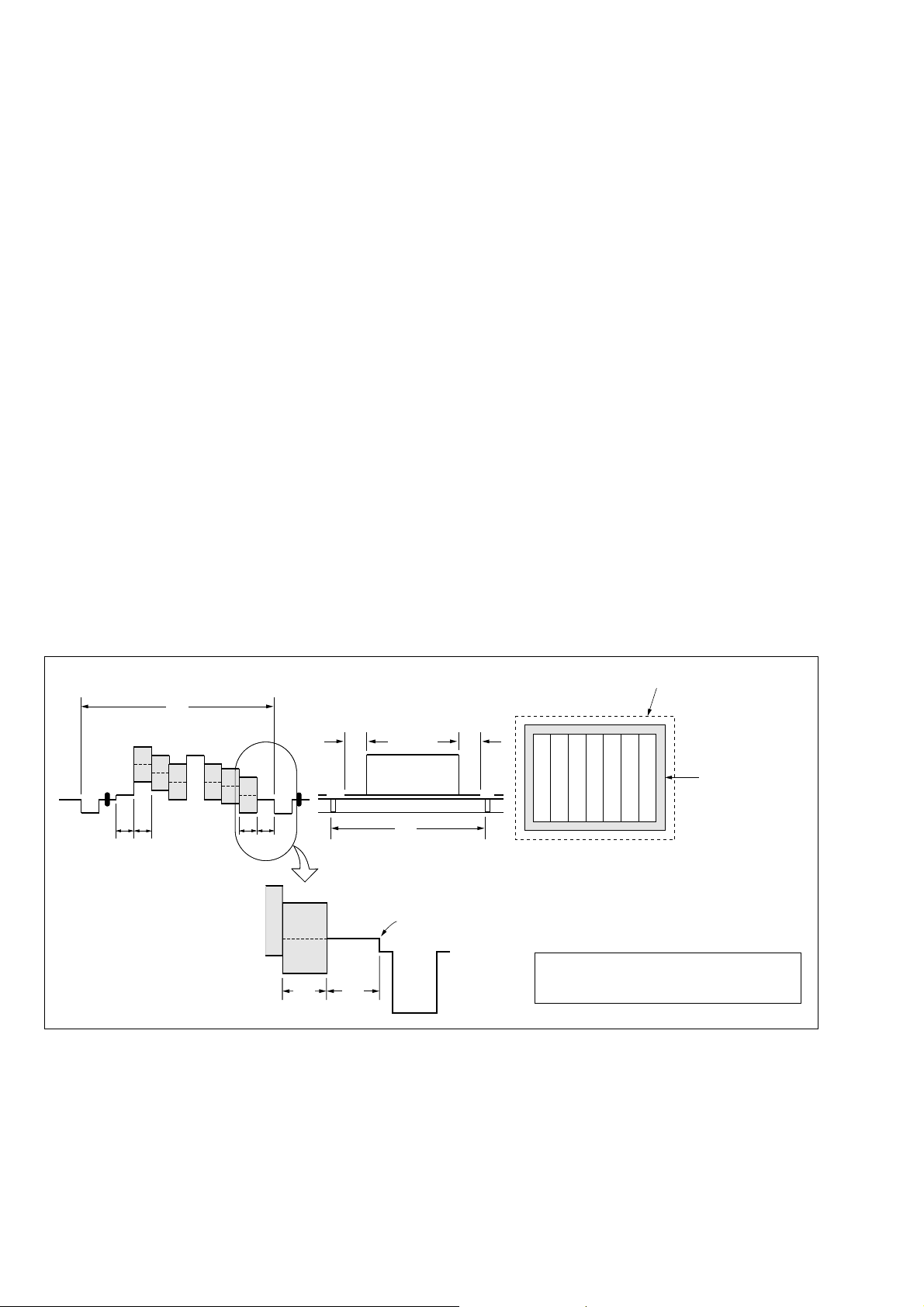
2. Order of Adjustments
Basically carry out adjustments in the order given.
Color bar chart (Color reproduction adjustment frame)
H
Yellow
Cyan
Green
AB B
Fig. a
(VIDEO terminal of A/V jack
output waveform)
A=B
White
Magenta
Red
Blue
A
B
CD
Enlargement
A
C=D
V
Difference in level
Fig. 6-1-4
Electronic beam scanning frame
Red
Cyan
White
Green
Yellow
Fig. b (monitor TV picture)
Adjust the camera zoom and direction to
obtain the output wavef orm shown in Fig. a and
the monitor TV display shown in Fig. b.
Blue
Magenta
CRT picture frame
DCR-HC17E/HC19E/HC21/HC21E/HC22E/HC32/HC32E/HC33/HC33E
6-8
Page 12

3. Subjects
1) Color bar chart (Color reproduction adjustment frame)
When performing adjustments using the color bar chart, adjust
the picture frame as shown in Fig. 6-1-4. (Color reproduction
adjustment frame)
2) Mixed color compensation chart (Color reproduction
adjustment frame)
Remove the color bar chart from the pattern box and insert a
mixed color compensation chart in its place. (Do not perform
zoom operations during this time)
3) Chart for flange back adjustment
Join together a piece of white A0 size paper (1189mm × 841
mm) and a piece of black paper to make the chart shown in
Fig. 6-1-5.
Note: Use a non-reflecting and non-glazing vellum paper. The
size must be A0 or larger and the joint between the white
and black paper must not have any undulations.
White
841 mm
Black
1189 mm
Fig. 6-1-5
DCR-HC17E/HC19E/HC21/HC21E/HC22E/HC32/HC32E/HC33/HC33E
6-9
Page 13
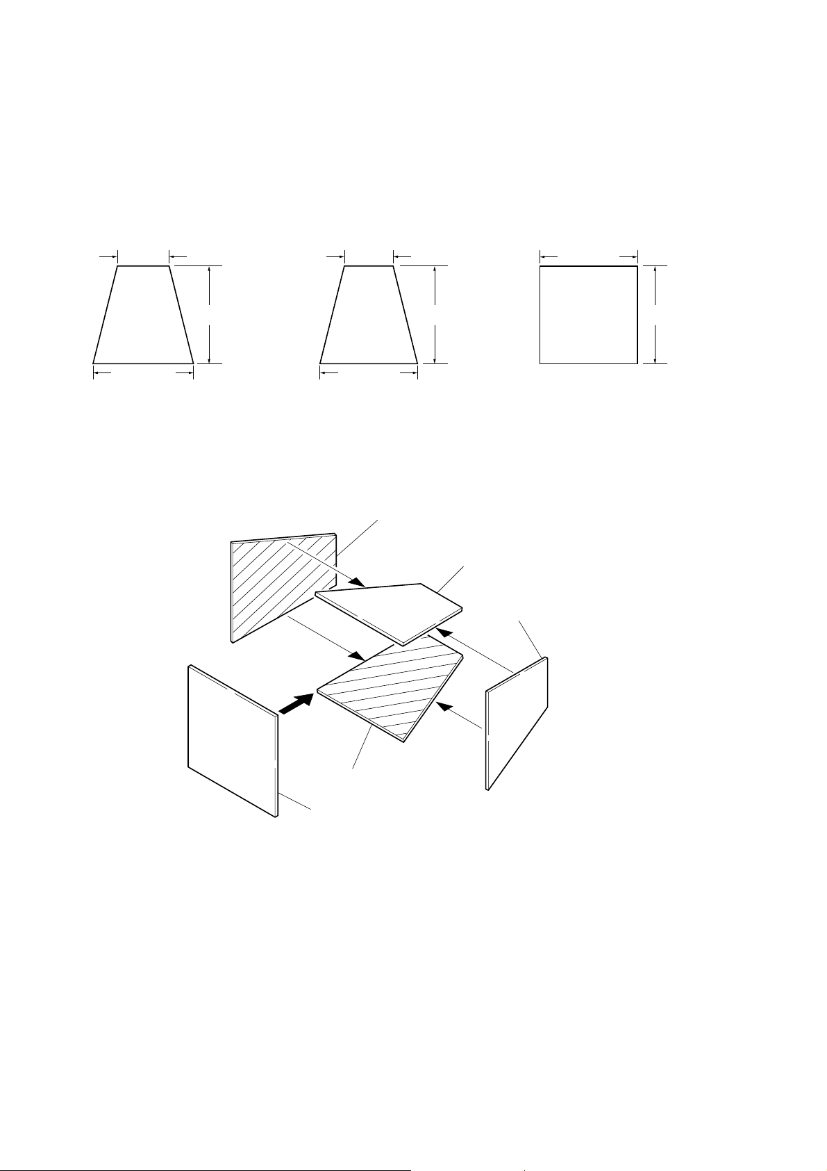
4. Preparing the Flash Adjustment Box
A dark room is required to provide an accurate flash adjustment.
If it is not available, prepare the flash adjustment box as given
below;
1) Provide woody board A, B and C of 15 mm thickness.
woody board A (2)
400 mm
513 mm 513 mm 700 mm
woody board B (2)
370 mm
700 mm730 mm
Fig. 6-1-6
2) Apply black mat paint to one side of woody board A and B.
3) Attach background paper (J-2501-130-A) to woody board C.
4) Assemble so that the black sides and the background paper
side of woody board A, B and C are internal. (Fig. 6-1-7)
woody board C (1)
700 mm
woody board A
woody board B
woody board A
woody board C
DCR-HC17E/HC19E/HC21/HC21E/HC22E/HC32/HC32E/HC33/HC33E
woody board B
Fig. 6-1-7
6-10
Page 14
1-2. INITIALIZATION OF 8, A, C, D, E, F, 1C, 1F
PAGE DATA (Non MS model)
Note 1: If reading/writing data on pages 1C, 1F, set data: 01 to
page: 0, address: 10, and then select pages C, F. By this
data setting, the pages 1C, 1F can be selected.
After the data reading/writing finished, return the data
on page: 0, address: 10 to “00”.
Note 2: Non MS model: DCR-HC17E/HC19E/HC21/HC21E/
HC22E
1-2-1. Initialization of A, D Page Data
Note: Check that the data of page: 0, address: 10 is “00”.
1. Initializing of A, D Page Data
Note 1: If “Initialization of Pages A, D” is executed, all data on
pages A, D are initialized.
Note 2: If the A, D page data has been initialized, the following
adjustments need to be performed again.
1) Modification of A, D page data
2) Touch panel adjustment
Note 3: NTSC model: DCR-HC21/HC32/HC33
PAL model: DCR-HC17E/HC19E/HC21E/HC22E/
HC32E/HC33E
Adjustment Page A
Adjustment Address 10 to FF
Adjustment Page D
Adjustment Address 10 to 7F
Initializing method:
Order Page Address Data Procedure
10 0101
20 1000
Set the following data.
37 03
47 00
57 01
67 02
7
01: NTSC model
81: PAL model
Set the following data.
20: Initializing A page
22: Initializing D page
28: Initializing A and D pages
Set the following data, and
press PAUSE button.
20: Initializing A page
22: Initializing D page
28: Initializing A and D pages
Check the data changes to
“01”.
Perform “Modification of A,
D Page Data”
2. Modification of A, D Page Data
If the A, D page data has been initialized, change the data of
the“Fixed data-2” address shown in the following table b y manual
input.
Modifying method:
1) Before changing the data, select page: 0, address: 01, and set
data: 01.
2) New data for changing are not shown in the tables because
they are different in destination. When changing the data, cop y
the data built in the same model.
Note 1: If copy the data built in the different model, the
camcorder may not operate.
3) When changing the data, press the PAUSE button of the adjustment remote commander each time when setting new data
to write the data in the non-volatile memory.
4) Check that the data of adjustment addresses is the initial value.
If not, change the data to the initial value.
Processing after completing modification A, D page data:
Order Page Address Data Procedure
12 0029
22 01 29 Press PAUSE button.
Note 2: If the following symptoms occur after completing of
the“Modification A, D page data”, check that the data of
the “Fixed data-2” addresses of A, D page are same as
those of the same model of the same destination.
1) The power is shut off so that unit cannot operate.
DCR-HC17E/HC19E/HC21/HC21E/HC22E/HC32/HC32E/HC33/HC33E
6-11
Page 15

3. A Page Table
Note 1: Check that the data of page: 0, address: 10 is “00”.
Note 2: Fixed data-1: Initialized data. (Refer to “1. Initializing
the A, D Page Data”)
Fixed data-2: Modified data. (Refer to “2. Modification
of A, D Page Data”)
4. D Page Table
Note 1: Check that the data of page: 0, address: 10 is “00”.
Note 2: Fixed data-1: Initialized data. (Refer to “1. Initializing
the A, D Page Data”)
Fixed data-2: Modified data. (Refer to “2. Modification
of A, D Page Data”)
Address
Initial value
NTSC PAL
Remark
10 to 19 Fixed data-1 (Initialized data)
1A
1B
Fixed data-2
1C to 30 Fixed data-1 (Initialized data)
31
32
Fixed data-2
33 to 38 Fixed data-1 (Initialized data)
39 Fixed data-2
3A to 43 Fixed data-1 (Initialized data)
44 Fixed data-2
45 to 4A Fixed data-1 (Initialized data)
4B Fixed data-2
4C Fixed data-1 (Initialized data)
4D Fixed data-2
4E Fixed data-1 (Initialized data)
4F Fixed data-2
50 to 52 Fixed data-1 (Initialized data)
53
54
Fixed data-2
55
56 to 79 Fixed data-1 (Initialized data)
7A
7B
Fixed data-2
7C to 7F Fixed data-1 (Initialized data)
80
81
Fixed data-2
82 CB CC
83 20 1D
Touch panel adj
84 CF C4
85 1C 28
86 to 8F Fixed data-1 (Initialized data)
90 Fixed data-2
91 to F0 Fixed data-1 (Initialized data)
F1
F2
Fixed data-2
F3
F4 to FF Fixed data-1 (Initialized data)
Address
Initial value
NTSC PAL
Remark
10 00 00 Test mode
11 Fixed data-1 (Initialized data)
12
13
Fixed data-2
14 to 16 Fixed data-1 (Initialized data)
17
18
Fixed data-2
19
1A to 21 Fixed data-1 (Initialized data)
22
23
24 Fixed data-2
25
26
27 to 29 Fixed data-1 (Initialized data)
2A
2B
Fixed data-2
2C to 36 Fixed data-1 (Initialized data)
37 Fixed data-2
38, 39 Fixed data-1 (Initialized data)
3A Fixed data-2
3B, 3C Fixed data-1 (Initialized data)
3D Fixed data-2
3E, 3F Fixed data-1 (Initialized data)
40 Fixed data-2
41 to 54 Fixed data-1 (Initialized data)
55
56 Fixed data-2
57
58 to 6E Fixed data-1 (Initialized data)
6F Fixed data-2
70 to 7F Fixed data-1 (Initialized data)
DCR-HC17E/HC19E/HC21/HC21E/HC22E/HC32/HC32E/HC33/HC33E
6-12
Page 16
1-2-2. Initialization of 8, C, 1C Page Data
Note: If reading/writing data on pages 1C, set data: 01 to page:
0, address: 10, and then select pages C. By this data setting, the pages 1C can be selected.
After the data reading/writing finished, return the data on
page: 0, address: 10 to “00”.
1. Initializing of 8, C, 1C Page Data
Note 1: If “Initialization of Pages 8, C, 1C” is executed, all data
on pages 8, C, 1C are initialized. (Only an individual
page cannot be initialized)
Note 2: If the 8, C, 1C page data has been initialized, the follow-
ing adjustments need to be performed again.
1) Modification of 8, C, 1C page data
2) Electronic viewfinder system adjustments
3) LCD system adjustments
4) Node unique ID No. input
5) Servo, RF system adjustments
6) Video system adjustments.
Adjustment Page 8
Adjustment Address 00 to FF
Adjustment Page C
Adjustment Address 10 to FF
Adjustment Page 1C
Adjustment Address 00 to FF
Initializing method:
Order Page Address Data Procedure
10 0101
20 1000
33 81 Check that the data is “00”.
43 80 0C Press PAUSE button.
53 80
6
Check the data changes to
“1C”.
Perform “Modification of 8,
C, 1C Page Data”
2. Modification of 8, C, 1C Page Data
If the 8, C, 1C page data has been initialized, change the data of
the “Fixed data-2” address shown in the following table by manual
input.
Modifying method:
1) Before changing the data, select page: 0, address: 01, and set
data: 01.
2) If modification of data on pages 8, C, set data: 00 to page: 0,
address: 10, and then select pages 8, C.
3) If modification of data on pages 1C, set data: 01 to page: 0,
address: 10, and then select pages C. After the modif ication of
data finished, return the data on page: 0, address: 10 to “00”.
4) New data for changing are not shown in the tables because
they are different in destination. When changing the data, cop y
the data built in the same model.
Note: If copy the data built in the different model, the
camcorder may not operate.
5) When changing the data, press the PAUSE button of the adjustment remote commander each time when setting new data
to write the data in the non-volatile memory.
6) Check that the data of adjustment addresses is the initial value.
If not, change the data to the initial value.
Processing after completing modification 8, C, 1C page data:
Order Page Address Data Procedure
10 1000
22 0029
32 01 29 Press PAUSE button.
DCR-HC17E/HC19E/HC21/HC21E/HC22E/HC32/HC32E/HC33/HC33E
6-13
Page 17
3. 8 Page Table
Note 1: Check that the data of page: 0, address: 10 is “00”.
Note 2: Fixed data-1: Initialized data. (Refer to “1. Initializing
the 8, C, 1C Page Data”)
Fixed data-2: Modified data. (Refer to “2. Modification
of 8, C, 1C Page Data”)
4. C Page Table
Note 1: Check that the data of page: 0, address: 10 is “00”.
Note 2: Fixed data-1: Initialized data. (Refer to “1. Initializing
the 8, C, 1C Page Data”)
Fixed data-2: Modified data. (Refer to “2. Modification
of 8, C, 1C Page Data”)
Address
Initial value
NTSC PAL
Remark
00 to 3F Fixed data-1 (Initialized data)
40 Fixed data-2
41 to 4C Fixed data-1 (Initialized data)
4D Fixed data-2
4E to 79 Fixed data-1 (Initialized data)
7A
7B
Fixed data-2
7C to 89 Fixed data-1 (Initialized data)
8A Fixed data-2
8B to 8D Fixed data-1 (Initialized data)
8E
8F
Fixed data-2
90 to B2 Fixed data-1 (Initialized data)
B3 Fixed data-2
B4 to BE Fixed data-1 (Initialized data)
BF Fixed data-2
C0 to C3 Fixed data-1 (Initialized data)
C4
C5
C6 Fixed data-2
C7
C8
C9 Fixed data-1 (Initialized data)
CA
CB
Fixed data-2
CC to D5 Fixed data-1 (Initialized data)
D6
D7
Fixed data-2
D8 to FF Fixed data-1 (Initialized data)
Address
Initial value
NTSC PAL
Remark
10 EE EE
11 00 00
12 00 00
Switching position adj.
13 00 00
14, 15 Fixed data-1 (Initialized data)
16 E0 E0 CAP FG duty adj.
17 to 24 Fixed data-1 (Initialized data)
25 80 80 S VIDEO OUT Y level adj.
26 90 90
27 65 65
S VIDEO OUT chroma level adj.
28 to 3B Fixed data-1 (Initialized data)
3C Fixed data-2
3D, 3E Fixed data-1 (Initialized data)
3F 6C 6C
40 90 90
EVF automatic adj. (VCO adj.)
41 to 44 Fixed data-1 (Initialized data)
45
46
Fixed data-2
47 28 28 EVF automatic adj. (Contrast adj.)
48 to 4C Fixed data-1 (Initialized data)
4D
4E
Fixed data-2
4F
50 6C 6C
51 90 90
LCD automatic adj. (VCO adj.)
52 BC BC V-COM adj. (LCD)
53, 54 Fixed data-1 (Initialized data)
55 Fixed data-2
56 7D 7D Transmissive mode white balans
57 73 73 adj. (LCD)
58 52 52 LCD automatic adj. (Contrast adj.)
59 to 5E Fixed data-1 (Initialized data)
5F Fixed data-2
60 to 65 Fixed data-1 (Initialized data)
66
67
Fixed data-2
68
69 to 74 Fixed data-1 (Initialized data)
75 Fixed data-2
76 to A8 Fixed data-1 (Initialized data)
A9 Fixed data-2
DCR-HC17E/HC19E/HC21/HC21E/HC22E/HC32/HC32E/HC33/HC33E
6-14
Page 18
C Page Table
Address
Initial value
NTSC PAL
Remark
AA Fixed data-1 (Initialized data)
AB
AC
Fixed data-2
AD to AF Fixed data-1 (Initialized data)
B0
B1 Fixed data-2
B2
B3 Fixed data-1 (Initialized data)
B4
B5
Fixed data-2
B6 to D1 Fixed data-1 (Initialized data)
D2
D3 Fixed data-2
D4
D5 to DD Fixed data-1 (Initialized data)
DE
DF
Fixed data-2
E0 to E4 Fixed data-1 (Initialized data)
E5 00 00
E6 00 00 Node unique ID No. Input
E7 00 00
E8 to F3 Fixed data-1 (Initialized data)
F4 00 00
F5 00 00
F6 00 00
F7 00 00
F8 00 00
F9 00 00
FA 00 00
Emergency memory address
(Mechanism section)
FB 00 00
FC 00 00
FD 00 00
FE 00 00
FF 00 00
5. 1C Page Table
Note 1: If reading/writing data on pages 1C, set data: 01 to page:
0, address: 10, and then select pages C. By this data setting, the pages 1C can be selected.
After the data reading/writing finished, return the data
on page: 0, address: 10 to “00”.
Note 2: Fixed data-1: Initialized data. (Refer to “1. Initializing
the 8, C, 1C Page Data”)
Fixed data-2: Modified data. (Refer to “2. Modification
of 8, C, 1C Page Data”)
Address
Initial value
NTSC PAL
Remark
00 to B2 Fixed data-1 (Initialized data)
B3 00 00
B4 00 00
B5 00 00
B6 00 00
B7 00 00
B8 80 80
B9 00 00
BA 00 00
BC 00 00
BD 00 00
BE 00 00
SD error rate check (LP)
BF 00 00
C0 00 00
C1 00 00
C2 00 00
C3 80 80
C4 00 00
C5 00 00
C6 00 00
C7 00 00
C8 00 00
C9 to E5 Fixed data-1 (Initialized data)
E6 Fixed data-2
E7 to E9 Fixed data-1 (Initialized data)
EA
EB
Fixed data-2
EC to EE Fixed data-1 (Initialized data)
EF
F0
Fixed data-2
F1 to FF Fixed data-1 (Initialized data)
DCR-HC17E/HC19E/HC21/HC21E/HC22E/HC32/HC32E/HC33/HC33E
6-15
Page 19

1-2-3. Initialization of E, F, 1F Page Data
Note: Check that the data of page: 0, address: 10 is “00”.
1. Initializing of E, F, 1F Page Data
Note 1: If “Initialization of Pages E, F, 1F” is executed, all data
on pages E, F , 1F are initialized. (Only an individual page
cannot be initialized)
Note 2: If the E, F , 1F page da ta has been initialized, the follow-
ing adjustments need to be performed again.
1) Modification of E, F, 1F page data
2) Camera system adjustments
Note 3: NTSC model: DCR-HC21/HC32/HC33
PAL model: DCR-HC17E/HC19E/HC21E/HC22E/
HC32E/HC33E
Adjustment Page E
Adjustment Address 00 to FF
Adjustment Page F
Adjustment Address 10 to FF
Adjustment Page 1F
Adjustment Address 00 to FF
Initializing method:
Order Page Address Data Procedure
10 0101
20 1000
Set the following data, and
36 01
press PAUSE button.
2D: NTSC model
2F: PAL model
46 03 FF Press PAUSE button.
56 02
Check the data changes to
“01”.
66 01 00 Press PAUSE button.
7
Perform “Modification of E,
F, 1F Page Data”
2. Modification of E, F, 1F Page Data
If the E, F, 1F page data has been initialized, change the data of
the “Fixed data-2” address shown in the following table by manual
input.
Modifying method:
1) Before changing the data, select page: 0, address: 01, and set
data: 01.
2) If modification of data on pages E, F, set data: 00 to page: 0,
address: 10, and then select pages E, F.
3) If modification of data on pages 1F, set data: 01 to page: 0,
address: 10, and then select pages F. After the modification of
data finished, return the data on page: 0, address: 10 to “00”.
4) New data for changing are not shown in the tables because
they are different in destination. When changing the data, cop y
the data built in the same model.
Note: If copy the data built in the different model, the
camcorder may not operate.
5) When changing the data, press the PAUSE button of the adjustment remote commander each time when setting new data
to write the data in the non-volatile memory.
6) Check that the data of adjustment addresses is the initial value.
If not, change the data to the initial value.
Processing after completing modification E, F, 1F page data:
Order Page Address Data Procedure
10 1000
22 0029
32 01 29 Press PAUSE button.
Perform “36MHz Origin
4
Oscillation Adjustment” of
CAMERA SYSTEM
ADJUSTMENTS.
DCR-HC17E/HC19E/HC21/HC21E/HC22E/HC32/HC32E/HC33/HC33E
6-16
Page 20
3. E Page Table
Note 1: Check that the data of page: 0, address: 10 is “00”.
Note 2: Fixed data-1: Initialized data. (Refer to “1. Initializing
the E, F, 1F Page Data”)
Fixed data-2: Modified data. (Refer to “2. Modification
of E, F, 1F Page Data”)
Address
Initial value
NTSC PAL
Remark
00 to 11 Fixed data-1 (Initialized data)
12 F i xed data-2
13, 14 Fixed data-1 (Initialized data)
15
16 F i xed data-2
17
18 to 34 Fixed data-1 (Initialized data)
35 F i xed data-2
36 to 41 Fixed data-1 (Initialized data)
42
43
44
45
46 F i xed data-2
47
48
49
4A
4B Fixed data-1 (Initialized data)
4C Fixed data-2
4D to 55 Fixed data-1 (Initialized data)
56
57
Fixed data-2
58 to 68 Fixed data-1 (Initialized data)
69 F i xed data-2
6A to 8D Fixed data-1 (Initialized data)
8E
8F
Fixed data-2
90 Fixed data-1 (Initialized data)
91 F i xed data-2
92 to A3 Fixed data-1 (Initialized data)
A4 Fixed data-2
A5 to BD F ixed data-1 (Initialized data)
BE Fixed data-2
BF to DA Fixed data-1 (Initialized data)
DB Fixed data-2
DC to E4 Fixed data-1 (Initialized data)
E5 Fixed data-2
E6 to FF Fixed data-1 (Initialized data)
4. F Page Table
Note 1: Check that the data of page: 0, address: 10 is “00”.
Note 2: Fixed data-1: Initialized data. (Refer to “1. Initializing
the E, F, 1F Page Data”)
Fixed data-2: Modified data. (Refer to “2. Modification
of E, F, 1F Page Data”)
Address
Initial value
NTSC PAL
Remark
10 80 80 36MHz origin osillation adj.
11 Fixed data-1 (Initialized data)
12 50 50
13 50 50
14 89 89
15 00 00
Hall adj.
16 17 17
17 00 00
18 00 00
19 A8 A8 MAX GAIN adj.
1A 36 36
LV standard data input
1B 00 00
1C 00 00
1D 00 00
1E 00 00
1F 00 00
20 00 00
F No. standard data input
21 00 00
22 00 00
23 00 00
24 to 29 Fixed data-1 (Initialized data)
2A 27 27
2B 00 00
2C 08 08
Auto white balance standard data
input
2D 00 00
2E 18 18
2F 00 00
30 0E 0E
Auto white balance adj.
31 00 00
32 Fixed data-1 (Initialized data)
33 48 47 Color reproduction adj.
34 Fixed data-1 (Initialized data)
35 2A 2B Color reproduction adj.
36 to 39 Fixed data-1 (Initialized data)
3A 00 FF
3B EF ED
Color reproduction adj.
3C, 3D Fixed data-1 (Initialized data)
3E 2A 2A
3F 00 C0
Auto white balance adj.
40 5D 5C
41 00 00
42, 43 Fixed data-1 (Initialized data)
DCR-HC17E/HC19E/HC21/HC21E/HC22E/HC32/HC32E/HC33/HC33E
6-17
Page 21
F Page Table
Address
Initial value
NTSC PAL
Remark
44 3A 3A
45 74 74
46 3F 3F
47 2C 2C
48 17 17
49 4A 4A
4A 00 00
4B 00 00
4C 00 00
Flange back adj.
4D 00 00
4E 4F 4F
4F 19 19
50 00 00
51 30 30
52 04 04
53 00 00
54 00 00
55 to 57 Fixed data-1 (Initialized data)
58
59
Fixed data-2
5A FF FF Optical axis adj.
5B to 67 Fixed data-1 (Initialized data)
68 00 00
69 00 00
6A 00 00
6B 00 00
6C 00 00
6D 00 00
6E 00 00
6F 00 00
70 00 00
71 00 00
72 00 00
73 00 00
Mechanical shutter adj.
74 00 00
75 00 00
76 00 00
77 00 00
78 00 00
79 00 00
7A 00 00
7B 00 00
7C 00 00
7D 00 00
Address
Initial value
NTSC PAL
Remark
7E to 8B Fixed data-1 (Initialized data)
8C
8D
8E
Fixed data-2
8F
90
91, 92 Fixed data-1 (Initialized data)
93
94
Fixed data-2
95
96
97, 98 Fixed data-1 (Initialized data)
99 Fixed data-2
9A to A8 Fixed data-1 (Initialized data)
A9
AA
AB
AC
AD
Fixed data-2
AE
AF
B0
B1 to EA Fixed data-1 (Initialized data)
EB Fixed data-2
EC, ED Fixed data-1 (Initialized data)
EE Fixed data-2
EF to FA Fixed data-1 (Initialized data)
FB Fixed data-2
FC to FF Fixed data-1 (Initialized data)
DCR-HC17E/HC19E/HC21/HC21E/HC22E/HC32/HC32E/HC33/HC33E
6-18
Page 22

5. 1F Page Table
Note 1: If reading/writing data on pages 1F , set data: 01 to page:
0, address: 10, and then select pages F. By this data setting, the pages 1F can be selected.
After the data reading/writing finished, return the data
on page: 0, address: 10 to “00”.
Note 2: Fixed data-1: Initialized data. (Refer to “1. Initializing
the E, F, 1F Page Data”)
Fixed data-2: Modified data. (Refer to “2. Modification
of E, F, 1F Page Data”)
Address
Initial value
NTSC PAL
Remark
00 to 07 Fixed data-1 (Initialized data)
08 F i xed data-2
09 to 59 Fixed data-1 (Initialized data)
5A 00 00 Emergency memory address
5B 00 00 (Camera section)
5C 00 00
5D 00 00
5E to FF Fixed data-1 (Initialized data)
DCR-HC17E/HC19E/HC21/HC21E/HC22E/HC32/HC32E/HC33/HC33E
6-19
Page 23

1-3. INITIALIZATION OF 8, A, B, C, D, E, F, 18, 19,
1A, 1B, 1C, 1E, 1F PAGE DATA (MS model)
Note 1: If reading/writing data on pages 18, 19, 1A, 1B, 1C, 1E,
1F, set data: 01 to page: 0, address: 10, and then select
pages: 8, 9, A, B, C, E, F.
By this data setting, the pages 18, 19, 1A, 1B, 1C, 1E,
1F, can be selected.
After the data reading/writing finished, return the data
on page: 0, address: 10 to “00”.
Note 2: MS model: DCR-HC32/HC32E/HC33/HC33E
1-3-1. Initialization of A, B, D, 1A, 1B Page Data
Note: Check that the data of page: 0, address: 10 is “00”.
1. Initializing of A, B, D, 1A, 1B Page Data
Note 1: If the A, B, D, 1A, 1B page data has been initialized, the
following adjustments need to be performed again.
1) Modification of A, B, D, 1A, 1B page data
2) Touch panel adjustment
Note 2: NTSC model: DCR-HC32/HC33
PAL model: DCR-HC32E/HC33E
Adjustment Page A
Adjustment Address 10 to FF
Adjustment Page B
Adjustment Address 00 to FF
Adjustment Page D
Adjustment Address 10 to 70
Adjustment Page 1A
Adjustment Address 00 to FF
Adjustment Page 1B
Adjustment Address 00 to FF
Initializing method:
Order Page Address Data Procedure
10 0101
20 1000
37 04
47 01
57 00 01 Press PAUSE button.
67 02
7
Set the following data
20: NTSC model
21: PAL model
Set the following data
20: Initializing A page
21: Initializing B page
22: Initializing D page
23: Initializing 1A page
24: Initializing 1B page
25: Initializing A and 1A
page
26: Initializing B and 1B
page
28: Initializing A, B, D, 1A
and 1B page
Check the data changes to
“01”.
Perform “Modification of A,
B, D, 1A, 1B Page Data”
2. Modification of A, B, D, 1A, 1B Page Data
If the A, B, D, 1A, 1B page data has been initialized, change the
data of the “Fixed data-2” address shown in the follo wing table by
manual input.
Modifying Method:
1) Before changing the data, select page: 0, address: 01, and set
data: 01.
2) If modification of data on pages A, B, D, set data: 00 to page:
0, address: 10, and then select pages A, B, D.
3) If modification of data on pages 1A, 1B, set data: 01 to page:
0, address: 10, and then select pages A, B.
After the modification of data finished, return the data on page:
0, address: 10 to “00”.
4) New data for changing are not shown in the tables because
they are different in destination. When changing the data, cop y
the data built in the same model.
Note 1: If copy the data built in the different model, the
camcorder may not operate.
5) When changing the data, press the PAUSE button of the adjustment remote commander each time when setting new data
to write the data in the non-volatile memory.
6) Check that the data of adjustment addresses is the initial value.
If not, change the data to the initial value.
Processing after Completing Modification A, B, D, 1A, 1B
page data:
Order Page Address Data Procedure
10 1000
22 0029
32 01 29 Press PAUSE button.
Note 2: If following symptoms occur after completing of the
“Modification A, B, D, 1A, 1B page data”, check that
the data of the “Fixed data-2” address of A, B, D, 1A, 1B
page are same as those of same model of same destination.
1) The power is shut off so that unit cannot operate.
DCR-HC17E/HC19E/HC21/HC21E/HC22E/HC32/HC32E/HC33/HC33E
6-20
Page 24
3. A Page table
Note 1: Check that the data of page: 0, address: 10 is“00”.
Note 2: Fixed data-1: Initialized data. (Refer to“1. Initializing the
A, B, D, 1A, 1B Page Data”)
Fixed data-2: Modified data. (Refer to“2. Modification
of A, B, D, 1A, 1B Page Data”)
Address
Initial value
NTSC PAL
Remark
10 00 00 Test mode
11 to 17 Fixed data-1 (Initialized data)
18 F i xed data-2
19 to 2E Fixed data-1 (Initialized data)
2F Fixed data-2
30 Fixed data-1 (Initialized data)
31 F i xed data-2
32 to 60 Fixed data-1 (Initialized data)
61
62 F i xed data-2
63
64 to 8F Fixed data-1 (Initialized data)
90 E0 DD
91 1D 1C
92 D4 C7
Touch panel adj
93 24 2A
94 to CF Fixed data-1 (Initialized data)
D0
D1 Fixed data-2
D2
D3, D4 Fixed data-1 (Initialized data)
D5 Fixed data-2
D6 Fixed data-1 (Initialized data)
D7 Fixed data-2
D8 Fixed data-1 (Initialized data)
D9 Fixed data-2
DA to F0 Fixed data-1 (Initialized data)
F1
F2 Fixed data-2
F3
F4 to FF Fixed data-1 (Initialized data)
4. B Page table
Note 1: Check that the data of page: 0, address: 10 is “00”.
Note 2: Fixed data-1: Initialized data. (Refer to “1. Initializing
the A, B, D, 1A, 1B Page Data”)
Fixed data-2: Modified data. (Refer to “2. Modification
of A, B, D, 1A, 1B Page Data”)
Address
Initial value
NTSC PAL
Remark
00 to FF Fixed data-1 (Initialized data)
5. D Page table
Note 1: Check that the data of page: 0, address: 10 is “00”.
Note 2: Fixed data-1: Initialized data. (Refer to “1. Initializing
the A, B, D, 1A, 1B Page Data”)
Fixed data-2: Modified data. (Refer to “2. Modification
of A, B, D, 1A, 1B Page Data”)
Address
Initial value
NTSC PAL
Remark
10 to 13 Fixed data-1 (Initialized data)
14 Fixed data-2
15 Fixed data-1 (Initialized data)
16
17
Fixed data-2
18 to 27 Fixed data-1 (Initialized data)
28
29
2A Fixed data-2
2B
2C
2D Fixed data-1 (Initialized data)
2E
2F Fixed data-2
30
31, 32 Fixed data-1 (Initialized data)
33 Fixed data-2
34 to 44 Fixed data-1 (Initialized data)
45 Fixed data-2
46, 47 Fixed data-1 (Initialized data)
48 Fixed data-2
49 Fixed data-1 (Initialized data)
4A
4B
Fixed data-2
4C Fixed data-1 (Initialized data)
4D
4E
Fixed data-2
4F to 56 Fixed data-1 (Initialized data)
57 Fixed data-2
58 to 70 Fixed data-1 (Initialized data)
DCR-HC17E/HC19E/HC21/HC21E/HC22E/HC32/HC32E/HC33/HC33E
6-21
Page 25

6. 1A Page table
Note 1: If reading/writing data on pages 1A, set data: 01 to page:
0, address: 10, and then select pages: A. By this data setting, the pages 1A can be selected.
After the data reading/writing finished, return the data
on page: 0, address: 10 to “00”.
Note 2: Fixed data-1: Initialized data. (Refer to “1. Initializing
the A, B, D, 1A, 1B Page Data”)
Fixed data-2: Modified data. (Refer to “2. Modification
of A, B, D, 1A, 1B Page Data”)
Address
Initial value
NTSC PAL
Remark
00 to FF Fixed data-1 (Initialized data)
7. 1B Page table
Note 1: If reading/writing data on pages 1B, set data: 01 to page:
0, address: 10, and then select pages: B. By this data setting, the pages 1B can be selected.
After the data reading/writing finished, return the data
on page: 0, address: 10 to “00”.
Note 2: Fixed data-1: Initialized data. (Refer to “1. Initializing
the A, B, D, 1A, 1B Page Data”)
Fixed data-2: Modified data. (Refer to “2. Modification
of A, B, D, 1A, 1B Page Data”)
Address
Initial value
NTSC PAL
Remark
00 to FF Fixed data-1 (Initialized data)
DCR-HC17E/HC19E/HC21/HC21E/HC22E/HC32/HC32E/HC33/HC33E
6-22
Page 26

1-3-2. Initialization of 8, C, 18, 1C Page Data
1. Initializing of 8, C, 18, 1C Page Data
Note1: If “Initialization of Pages 8, C, 18, 1C” is executed, all
data on pages 8, C, 18, 1C are initialized. (Only an individual page cannot be initialized)
Note2 : If the 8, C, 18, 1C page data has been initialized, the
following adjustments need to be performed again.
1) Modification of 8, C, 18, 1C page data
2) Electronic viewfinder system adjustments (if all areas
were initialized)
3) LCD system adjustments (if all areas were initialized)
4) Node unique ID No. input (if all areas were initialized)
5) Servo, RF system adjustments (if all areas were initialized)
6) Video system adjustments (if all areas were initialized)
Adjustment Page 8
Adjustment Address 00 to FF
Adjustment Page C
Adjustment Address 10 to FF
Adjustment Page 18
Adjustment Address 00 to FF
Adjustment Page 1C
Adjustment Address 00 to FF
Initializing method:
Order Page Address Data Procedure
10 0101
20 1000
33 81 Check the data is “00”.
43 80 0C Press PAUSE button.
53 80
6
Check the data changes to
“1C”.
Perform “Modification of 8,
C, 18, 1C Page Data”
Note 3: If other than adjustment address was initialized, the ad-
justed data is not initialized.
2. Modification of 8, C, 18, 1C Page Data
If the 8, C, 18, 1C page data has been initialized, change the data
of the “Fixed data-2” address shown in the following table by
manual input.
Modifying Method:
1) Before changing the data, select page: 0, address: 01, and set
data: 01.
2) If modification of data on pages 8, C, set data: 00 to page: 0,
address: 10, and then select pages 8, C.
3) If modification of data on pages 18, 1C, set data: 01 to page:
0, address: 10, and then select pages 8, C.
After the modification of data finished, return the data on page:
0, address: 10 to “00”.
4) New data for changing are not shown in the tables because
they are different in destination. When changing the data, cop y
the data built in the same model.
Note: If copy the data built in the different model, the
camcorder may not operate.
5) When changing the data, press the PAUSE button of the adjustment remote commander each time when setting new data
to write the data in the non-volatile memory.
6) If all areas were initialized, check that the data at the addresses
for adjustment are initial values (adjustment initial values)
listed in the table.
If different, change them to the adjustment initial values.
Processing after Completing Modification 8, C, 18, 1C page
data:
Order Page Address Data Procedure
10 1000
22 0029
32 01 29 Press PAUSE button.
DCR-HC17E/HC19E/HC21/HC21E/HC22E/HC32/HC32E/HC33/HC33E
6-23
Page 27
3. 8 Page table
Note 1: Check that the data of page: 0, address: 10 is“00”.
Note 2: Fixed data-1: Initialized data. (Refer to “1. Initializing
the 8, C, 18, 1C Page Data”)
Fixed data-2: Modified data. (Refer to “2. Modification
of 8, C, 18, 1C Page Data”)
Address
Initial value
NTSC PAL
Remark
00 to 29 Fixed data-1 (Initialized data)
2A Fixed data-2
2B to 3F Fixed data-1 (Initialized data)
40 Fixed data-2
41 to 4C Fixed data-1 (Initialized data)
4D Fixed data-2
4E to 79 Fixed data-1 (Initialized data)
7A
7B
Fixed data-2
7C to 83 Fixed data-1 (Initialized data)
84
85
86
87
Fixed data-2
88
89
8A to 8D Fixed data-1 (Initialized data)
8E
8F
Fixed data-2
90 to A8 Fixed data-1 (Initialized data)
A9 Fixed data-2
AA, AB Fixed data-1 (Initialized data)
AC Fixed data-2
AD to B1 Fixed data-1 (Initialized data)
B2
B3 Fixed data-2
B4
B5 Fixed data-1 (Initialized data)
B6 Fixed data-2
B7 Fixed data-1 (Initialized data)
B8
B9
BA
Fixed data-2
BB
BC, BD Fixed data-1 (Initialized data)
BE
BF
Fixed data-2
C0 to C2 Fixed data-1 (Initialized data)
C3
C4 Fixed data-2
C5
Address
Initial value
NTSC PAL
Remark
C6 Fixed data-1 (Initialized data)
C7
C8
C9
CA Fixed data-2
CB
CC
CD
CE to D5 Fixed data-1 (Initialized data)
D6
D7
Fixed data-2
D8 to DF Fixed data-1 (Initialized data)
E0 Fixed data-2
E1 Fixed data-1 (Initialized data)
E2
E3
E4
E5
Fixed data-2
E6
E7
E8 to EF Fixed data-1 (Initialized data)
F0 Fixed data-2
F1 to F9 Fixed data-1 (Initialized data)
FA
FB
Fixed data-2
FC to FF Fixed data-1 (Initialized data)
DCR-HC17E/HC19E/HC21/HC21E/HC22E/HC32/HC32E/HC33/HC33E
6-24
Page 28

4. C Page table
Note 1: Check that the data of page: 0, address: 10 is “00”.
Note 2: Fixed data-1: Initialized data. (Refer to “1. Initializing
the 8, C, 18, 1C Page Data”)
Fixed data-2: Modified data. (Refer to “2. Modification
of 8, C, 18, 1C Page Data”)
Address
Initial value
NTSC PAL
Remark
10 EE EE
11 00 00
Switching position adj.
12 00 00
13 00 00
14, 15 Fixed data-1 (Initialized data)
16 E0 E0 CAP FG duty adj.
17 to 24 Fixed data-1 (Initialized data)
25 80 80 S VIDEO OUT Y level adj.
26 54 54
27 3D 3D
S VIDEO OUT chroma level adj.
28 to 3B Fixed data-1 (Initialized data)
3C
3D Fixed data-2
3E
3F A0 A0
40 B0 B0
EVF automatic adj. (VCO adj.)
41 Fixed data-1 (Initialized data)
42 F i xed data-2
43 Fixed data-1 (Initialized data)
44
45 F i xed data-2
46
47 28 28 EVF automatic adj. (Contrast adj.)
48
49
Fixed data-2
4A, 4B Fixed data-1 (Initialized data)
4C
4D
4E
Fixed data-2
4F
50 A0 A0
51 B0 B0
LCD automatic adj. (VCO adj.)
52 BC BC V-COM adj. (LCD)
53, 54 Fixed data-1 (Initialized data)
55 F i xed data-2
56 88 88
Transmissive mode white balans
57 71 71 adj. (LCD)
58 50 50 LCD automatic adj. (Contrast adj.)
59 F i xed data-2
5A to 5E Fixed data-1 (Initialized data)
5F Fixed data-2
Address
Initial value
NTSC PAL
Remark
60, 61 Fixed data-1 (Initialized data)
62
63
Fixed data-2
64, 65 Fixed data-1 (Initialized data)
66
67 Fixed data-2
68
69, 6A Fixed data-1 (Initialized data)
6B Fixed data-2
6C to 74 Fixed data-1 (Initialized data)
75 Fixed data-2
76 to 78 Fixed data-1 (Initialized data)
79
7A
7B
Fixed data-2
7C
7D Fixed data-1 (Initialized data)
7E Fixed data-2
7F to A0 Fixed data-1 (Initialized data)
A1
A2
A3
Fixed data-2
A4
A5 to A8 Fixed data-1 (Initialized data)
A9
AA
AB
Fixed data-2
AC
AD to B1 Fixed data-1 (Initialized data)
B2
B3
B4
Fixed data-2
B5
B6 to CB Fixed data-1 (Initialized data)
CC
CD
CE
CF
D0 Fixed data-2
D1
D2
D3
D4
D5 to DD Fixed data-1 (Initialized data)
DE
DF
Fixed data-2
DCR-HC17E/HC19E/HC21/HC21E/HC22E/HC32/HC32E/HC33/HC33E
6-25
Page 29

C Page table
Address
Initial value
NTSC PAL
Remark
E0 to E4 Fixed data-1 (Initialized data)
E5 00 00
E6 00 00 Node unique ID No. Inputs
E7 00 00
E8 to F3 Fixed data-1 (Initialized data)
F4 00 00
F5 00 00
F6 00 00
F7 00 00
F8 00 00
F9 00 00
FA 00 00
Emergency memory address
(Mechanism section)
FB 00 00
FC 00 00
FD 00 00
FE 00 00
FF 00 00
5. 18 Page table
Note 1: If reading/writing data on pages 18, set data: 01 to page:
0, address: 10, and then select pages: 8. By this data setting, the pages 18 can be selected.
After the data reading/writing finished, return the data
on page: 0, address: 10 to“00”.
Note 2: Fixed data-1: Initialized data. (Refer to “1. Initializing
the 8, C, 18, 1C Page Data”)
Fixed data-2: Modified data. (Refer to “2. Modification
of 8, C, 18, 1C Page Data”)
Address
Initial value
NTSC PAL
Remark
00 Fixed data-1 (Initialized data)
01 Fixed data-2
02 to FF Fixed data-1 (Initialized data)
DCR-HC17E/HC19E/HC21/HC21E/HC22E/HC32/HC32E/HC33/HC33E
6-26
Page 30

6. 1C Page table
Note 1: If reading/writing data on pages 1C, set data: 01 to page:
0, address: 10, and then select pages: C. By this data setting, the pages 1C can be selected.
After the data reading/writing finished, return the data
on page: 0, address: 10 to“00”.
Note 2: Fixed data-1: Initialized data. (Refer to “1. Initializing
the 8, C, 18, 1C Page Data”)
Fixed data-2: Modified data. (Refer to “2. Modification
of 8, C, 18, 1C Page Data”)
Address
Initial value
NTSC PAL
Remark
00 to B2 Fixed data-1 (Initialized data)
B3 00 00
B4 00 00
B5 00 00
B6 00 00
B7 00 00
B8 80 80
B9 00 00
BA 00 00
BB 00 00
BC 00 00
BD 00 00
BE 00 00
SD error rate check (LP)
BF 00 00
C0 00 00
C1 00 00
C2 00 00
C3 80 80
C4 00 00
C5 00 00
C6 00 00
C7 00 00
C8 00 00
C9 to E5 Fixed data-1 (Initialized data)
E6 Fixed data-2
E7 Fixed data-1 (Initialized data)
E8
When IC5301 is Type A.
(This data vary according to the
00 00
type of the IC5301 of VC-37
board.) (Note 3)
When IC5301 is Type B.
(This data vary according to the
1E 1E
type of the IC5301 of VC-377
board.) (Note 3)
E9 Fixed data-1 (Initialized data)
EA
EB
Fixed data-2
EC to EE Fixed data-1 (Initialized data)
Address
EF
F0
Initial value
NTSC PAL
Remark
Fixed data-2
F1 to F7 Fixed data-1 (Initialized data)
When IC5301 is Type A.
(This data vary according to the
00 00
F8
type of the IC5301 of VC-377
board.) (Note 3)
When IC5301 is Type B.
(This data vary according to the
60 60
type of the IC5301 of VC-377
board.) (Note 3)
F9 to FF Fixed data-1 (Initialized data)
Note 3: By checking the data of page: 6, address: FF, the type of
IC5301 of VC-377 board can be discriminated.
Order Page Address Data Procedure
10 1000
Check the data.
26 FF
01: Type A
02 or more: Type B
DCR-HC17E/HC19E/HC21/HC21E/HC22E/HC32/HC32E/HC33/HC33E
6-27
Page 31

1-3-3. Initialization of E, F, 19, 1E, 1F Page Data
1. Initializing of E, F, 19, 1E, 1F Page Data
Note 1: If “Initialization of Pages E, F, 19, 1E, 1F” is executed,
all data on pages E, F , 19, 1E, 1F are initialized. (Only an
individual page cannot be initialized)
Note 2: If the E, F, 19, 1E, 1F page data has been initialized, the
following adjustments need to be performed again.
1) Modification of E, F, 19, 1E, 1F page da ta
2) Camera system adjustment (if all areas were initialized)
Note 3: NTSC model: DCR-HC32/HC33
PAL model: DCR-HC32E/HC33E
Adjustment Page E
Adjustment Address 00 to FF
Adjustment Page F
Adjustment Address 10 to FF
Adjustment Page 19
Adjustment Address 00 to 33
Adjustment Page 1E
Adjustment Address 00 to FF
Adjustment Page 1F
Adjustment Address 00 to FF
Initializing method:
Order Page Address Data Procedure
10 0101
20 1000
Set the following data
36 01 2D: NTSC model
2F: PAL model
46 03 FF Press PAUSE button.
56 02
Check the data changes to
“01”.
66 01 00 Press PAUSE button.
7
Perform “Modification of E,
F, 19, 1E, 1F Page Data”
2. Modification of E, F, 19, 1E, 1F Page Data
If the E, F, 19, 1E, 1F page data has been initialized, change the
data of the “Fixed data-2” address shown in the follo wing table by
manual input.
Modifying Method:
1) Before changing the data, select page: 0, address: 01, and set
data: 01.
2) If modification of data on pages E, F, set data: 00 to page: 0,
address: 10, and then select pages E, F.
3) If modification of data on pages 19, 1E, 1F, set data: 01 to
page: 0, address: 10, and then select pages 9, E, F.
After the modification of data finished, return the data on page:
0, address: 10 to “00”.
4) New data for changing are not shown in the tables because
they are different in destination. When changing the data, cop y
the data built in the same model.
Note: If copy the data built in the different model, the
camcorder may not operate.
5) When changing the data, press the PAUSE button of the adjustment remote commander each time when setting new data
to write the data in the non-volatile memory.
6) If all areas were initialized, check that the data at the addresses
for adjustment are initial values (adjustment initial values)
listed in the table.
If different, change them to the adjustment initial values.
Processing after Completing Modification E, F, 19, 1E, 1F
page data:
Order Page Address Data Procedure
10 1000
22 0029
32 01 29 Press PAUSE button.
Perform “36MHz Origin
4
Oscillation Adjustment” of
CAMERA SYSTEM
ADJUSTMENTS.
DCR-HC17E/HC19E/HC21/HC21E/HC22E/HC32/HC32E/HC33/HC33E
6-28
Page 32

3. E Page table
Note 1: Check that the data of page: 0, address: 10 is “00”.
Note 2: Fixed data-1: Initialized data. (Refer to“1. Initializing the
E, F, 19, 1E, 1F Page Data”)
Fixed data-2: Modified data. (Refer to“2. Modification
of E, F, 19, 1E, 1F Page Data”)
Address
Initial value
NTSC PAL
Remark
00 to 07 Fixed data-1 (Initialized data)
08
09
Fixed data-2
0A to 11 Fixed data-1 (Initialized data)
12 F i xed data-2
13, 14 Fixed data-1 (Initialized data)
15
16 F i xed data-2
17
18 to 34 Fixed data-1 (Initialized data)
35 F i xed data-2
36 to 68 Fixed data-1 (Initialized data)
69 F i xed data-2
6A to 8D Fixed data-1 (Initialized data)
8E
8F
Fixed data-2
90 Fixed data-1 (Initialized data)
91 F i xed data-2
92 to A3 Fixed data-1 (Initialized data)
A4 Fixed data-2
A5 to AA Fixed data-1 (Initialized data)
AB Fixed data-2
AC to AF Fixed data-1 (Initialized data)
B0 Fixed data-2
B1 Fixed data-1 (Initialized data)
B2
B3
Fixed data-2
B4 to BD Fixed data-1 (Initialized data)
BE Fixed data-2
BF to E2 Fixed data-1 (Initialized data)
E3
E4 Fixed data-2
E5
E6 to FF Fixed data-1 (Initialized data)
4. F Page table
Note 1: Check that the data of page: 0, address: 10 is “00”.
Note 2: Fixed data-1: Initialized data. (Refer to“1. Initializing the
E, F, 19, 1E, 1F Page Data”)
Fixed data-2: Modified data. (Refer to“2. Modification
of E, F, 19, 1E, 1F Page Data”)
Address
Initial value
NTSC PAL
Remark
10 80 80 36MHz origin osillation adj.
11 Fixed data-1 (Initialized data)
12 50 50
13 50 50
14 89 89
15 00 00
Hall adj.
16 17 17
17 00 00
18 19 19
19 9A 9A MAX GAIN adj.
1A 36 36
1B 00 00
LV standard data input
1C 00 00
1D 00 00
1E 00 00
1F 00 00
F No. standard data input
20 00 00
21 00 00
22 00 00
23 00 00
24 to 29 Fixed data-1 (Initialized data)
2A 1B 1B
2B 00 00
2C 07 07
Auto white balance standard data
input
2D 00 00
2E 0E 0E
2F 00 00
Auto white balance adj.
30 0D 0D
31 00 00
32 Fixed data-1 (Initialized data)
33 22 22 Color reproduction adj.
34 Fixed data-1 (Initialized data)
35 27 24 Color reproduction adj.
36 to 39 Fixed data-1 (Initialized data)
3A 00 00
3B F1 EF
Color reproduction adj.
3C, 3D Fixed data-1 (Initialized data)
3E 2C 2C
3F B0 B0
40 5F 5F
Auto white balance adj.
41 A0 A0
42, 43 Fixed data-1 (Initialized data)
DCR-HC17E/HC19E/HC21/HC21E/HC22E/HC32/HC32E/HC33/HC33E
6-29
Page 33

F Page table
Address
Initial value
NTSC PAL
Remark
44 3A 3A
45 74 74
46 3F 3F
47 2C 2C
48 17 17
49 4A 4A
4A 00 00
4B 00 00
4C 00 00
4D 00 00
Flange back adj.
4E 4F 4F
4F 19 19
50 00 00
51 30 30
52 04 04
53 00 00
54 00 00
55 00 00
56 to 63 Fixed data-1 (Initialized data)
64
65
Fixed data-2
66 FF FF Optical axis adj.
67 Fixed data-1 (Initialized data)
68 80 80
69 80 80
6A 80 80
6B 80 80
6C 80 80
6D 80 80
6E 40 40
6F 00 00
70 34 34
71 00 00
72 30 30
73 00 00
Mechanical shutter adj.
74 2A 2A
75 00 00
76 14 14
77 00 00
78 70 70
79 80 80
7A 80 80
7B 80 80
7C 80 80
7D 1E 1E
Address
Initial value
NTSC PAL
Remark
7E to 8B Fixed data-1 (Initialized data)
8C
8D
8E Fixed data-2
8F
90
91, 92 Fixed data-1 (Initialized data)
93
94
95 Fixed data-2
96
97
98 Fixed data-1 (Initialized data)
99 Fixed data-2
9A to A8 Fixed data-1 (Initialized data)
A9
AA
AB
AC
AD
Fixed data-2
AE
AF
B0
B1 to E4 Fixed data-1 (Initialized data)
E5 Fixed data-2
E6 to EA Fixed data-1 (Initialized data)
EB Fixed data-2
EC, ED Fixed data-1 (Initialized data)
EE
EF
F0
F1 Fixed data-2
F2
F3
F4
F5 Fixed data-1 (Initialized data)
F6
F7
F8
F9
FA
FB
Fixed data-2
FC
FD
FE
FF
DCR-HC17E/HC19E/HC21/HC21E/HC22E/HC32/HC32E/HC33/HC33E
6-30
Page 34

5. 19 Page table
Note 1: If reading/writing data on pages 19, set data: 01 to
page: 0, address: 10, and then select pages: 9. By this
data setting, the pages 19 can be selected.
After the data reading/writing finished, return the data
on page: 0, address: 10 to “00”.
Note 2: Fixed data-1: Initialized data. (Refer to“1. Initializing the
E, F, 19, 1E, 1F Page Data”)
Fixed data-2: Modified data. (Refer to“2. Modification
of E, F, 19, 1E, 1F Page Data”)
Address
Initial value
NTSC PAL
Remark
00 to 33 Fixed data-1 (Initialized data)
6. 1E Page table
Note 1: If reading/writing data on pages 1E, set data: 01 to
page: 0, address: 10, and then select pages: E. By this
data setting, the pages 1E can be selected.
After the data reading/writing finished, return the data
on page: 0, address: 10 to “00”.
Note 2: Fixed data-1: Initialized data. (Refer to“1. Initializing the
E, F, 19, 1E, 1F Page Data”)
Fixed data-2: Modified data. (Refer to“2. Modification
of E, F, 19, 1E, 1F Page Data”)
Address
Initial value
NTSC PAL
Remark
00 to FF Fixed data-1 (Initialized data)
DCR-HC17E/HC19E/HC21/HC21E/HC22E/HC32/HC32E/HC33/HC33E
6-31
Page 35

7. 1F Page table
Note 1: If reading/writing data on pages 1F, set data: 01 to
page: 0, address: 10, and then select pages: F. By this
data setting, the pages 1F can be selected.
After the data reading/writing finished, return the data
on page: 0, address: 10 to “00”.
Note 2: Fixed data-1: Initialized data. (“Refer to 1. Initializing
the E, F, 19, 1E, 1F Page Data”)
Fixed data-2: Modified data. (“Refer to 2. Modification
of E, F, 19, 1E, 1F Page Data”)
Address
Initial value
NTSC PAL
Remark
00 to 07 Fixed data-1 (Initialized data)
08 Fixed data-2
09 to 1B Fixed data-1 (Initialized data)
1C 00 00
1D 00 00
1E 00 00
Emergency memory address
(Camera section)
1F 00 00
20 to 29 Fixed data-1 (Initialized data)
2A
2B
Fixed data-2
2C Fixed data-1 (Initialized data)
2D
2E
Fixed data-2
2F to 6B Fixed data-1 (Initialized data)
6C Fixed data-2
6D Fixed data-1 (Initialized data)
6E Fixed data-2
6F to 84 Fixed data-1 (Initialized data)
85
86 Fixed data-2
87
88 to 8A Fixed data-1 (Initialized data)
8B Fixed data-2
8C to A8 Fixed data-1 (Initialized data)
A9
AA
AB
AC
AD Fixed data-2
AE
AF
B0
B1
B2 Fixed data-1 (Initialized data)
B3 Fixed data-2
B4 to FF Fixed data-1 (Initialized data)
DCR-HC17E/HC19E/HC21/HC21E/HC22E/HC32/HC32E/HC33/HC33E
6-32
Page 36

1-4. CAMERA SYSTEM ADJUSTMENTS
Before perform the camera system adjustments, check that the
specified values of “VIDEO SYSTEM ADJUSTMENTS” are satisfied. (Except “36MHz Origin Oscillation Adjustment”)
Check that the data of page: 0, address: 10 is “00”.
If not, select page: 0, address: 10, and set the data “00”.
Note : Non MS model: DCR-HC17E/HC19E/HC21/HC21E/
HC22E
MS model: DCR-HC32/HC32E/HC33/HC33E
1. 36MHz Origin Oscillation Adjustment
(VC-376 board (Non MS model))
(VC-377 board (MS model))
Set the frequency of the clock for synchronization.
If deviated, the synchronization will be disrupted and the color
will become inconsistent.
Subject Not required
Measurement Point Pin qs of IC3001 (Non MS model)
Pin qs of IC3101 (MS model)
Measuring Instrument Frequency counter
Adjustment Page F
Adjustment Address 10
Specified value f = 18000000 ± 90 Hz
Non MS model
VC-376 board (SIDE A)
MS model
VC-377 board (SIDE A)
25
36
37
48
24
IC3001
13
12
1
Note 1: Check that the data of page: 0, address: 10 is “00”.
Adjusting method:
Order Page Address Data Procedure
10 0101
Change the data and set the
2F 10
frequency (f) to the specified
value.
3F 10 Press PAUSE button.
40 0100
37
48
2536
1
12
Fig. 6-1-8
24
13
IC3101
DCR-HC17E/HC19E/HC21/HC21E/HC22E/HC32/HC32E/HC33/HC33E
6-33
Page 37

2. HALL Adjustment
For detecting the position of lens iris, adjust the hall AMP gain
and offset.
Subject Not required
Measurement Point Displayed data of page: 1 (Note 3)
Measuring Instrument Adjusting remote commander
Adjustment Page F
Adjustment Address 12 to 18
Specified value Non MS model:
Note 1: Check that the data of page: 0, address: 10 is “00”.
Note 2: Check that the data of page: 6, address: 02 is “00”.
If not, select page: 6, address: 01, set data: 00, and press
the PAUSE button.
Note 3: The right two digits of the page: 1 displayed data of the
adjusting remote commander.
1:00:XX
Note 4: Non MS model: DCR-HC17E/HC19E/HC21/HC21E/
MS model: DCR-HC32/HC32E/HC33/HC33E
RadarWRadarWRadarW
87 to 8B during IRIS OPEN
15 to 19 during IRIS CLOSE
MS model:
15 to 19 during IRIS OPEN
87 to 8B during IRIS CLOSE
Displayed data
HC22E
Processing after completing adjustment:
Order Page Address Data Procedure
16 01 00 Press PAUSE button.
20 0300
30 0100
Switch setting:
1) POWER.............................CAMERA mode (Non MS model)
CAMERA-TAPE mode (MS model)
Adjusting method:
Order Page Address Data Procedure
10 0101
26 D0 40 Non MS model only. (Note 4)
36 01 6D Press PAUSE button. (Note 5)
46 02
Note 5: The adjustment data will be automatically input to page:
F, address: 12 to 18.
Checking method:
Order Page Address Data Procedure
10 0303
26 01 01 Press PAUSE button.
31
46 01 03 Press PAUSE button.
51
Check the data changes to
“01”.
Check that the displayed data
(Note 3) during IRIS OPEN
satisfied the specified value.
Check that the displayed data
(Note 3) during IRIS CLOSE
satisfied the specified value.
DCR-HC17E/HC19E/HC21/HC21E/HC22E/HC32/HC32E/HC33/HC33E
6-34
Page 38

RadarW
RadarW
RadarW
Minipattern box
Below 3 cm
Camcorder
Red (+)
Black (–)
Yellow (SENS +)
White (SENS –)
Black (GND)
Need not connected
Regulated power supply
Output voltage : Specified voltage ±0.01 Vdc
Output current : more than 3.5 A
Flange back adjustment jig
Below 3 cm
Camera
RadarW
3. Flange Back Adjustment
RadarW
(Using the minipattern box or flange back adjustment
jig)
The inner focus lens flange back adjustment is carried out
automatically. In whichever case, the focus will be deviated during auto focusing/manual focusing.
Subject Siemens star chart with ND filter for
minipattern box (Note 1) or flange
back adjustment jig
Measurement Point Check operation on monitor TV
Measuring Instrument
Adjustment Page F
Adjustment Address Non MS model: 44 to 54
MS model: 44 to 55
Specified value Data of page: 6, address: 0C is “00”
Note 1: Dark Siemens star chart.
Note 2: Check that the data of page: 0, address: 10 is “00”.
Note 3: Check that the data of page: 6, address: 02 is “00”.
If not, select page: 6, address: 01, set data: 00, and press
the PAUSE button.
Note 4: Perform the adjustment with the camcorder in horizon-
tal state.
Note 5: Perform “HALL Adjustment” before this adjustment.
Note 6: Non MS model: DCR-HC17E/HC19E/HC21/HC21E/
HC22E
MS model: DCR-HC32/HC32E/HC33/HC33E
Preparations (Using the minipattern box)
1) The minipattern box is installed as shown in the following figure.
Note 8: The attachment lenses are not used.
2) Install the minipattern box so that the distance between it and
the front of lens of camcorder is less than 3 cm.
3) Make the height of minipattern box and the camera equal.
4) Check the output voltage of the regulated power supply is the
specified voltage ± 0.01 Vdc.
5) Check that the center of Siemens star chart meets the center of
shot image screen with the zoom lens at TELE end and WIDE
end respectively.
Specified voltage: The specified voltage varies according to the
minipattern box, so adjust the power supply
output voltage to the specified voltage written
on the sheet which is supplied with the
minipattern box.
Switch setting:
1) POWER............................ CAMERA mode (Non MS model)
CAMERA-TAPE mode (MS model)
2) NIGHTSHOT PLUS........................................................ OFF
3) COLOR SLOW S (Menu setting) ...............OFF (MS model)
Adjusting method:
Order Page Address Data Procedure
10 0101
26 4801
36 01 13 Press PAUSE button.
46 01 27 Press P AUSE button. (Note 7)
56 02
Check the data changes to
“01”.
66 0C Check the data is “00”.
Note 7: The adjustment data will be automatically input to page:
F, address: 44 to 54 (Non MS model)/44 to 55 (MS
model).
Processing after completing adjustment:
Order Page Address Data Procedure
16 01 00 Press PAUSE button.
26 01 25 Press PAUSE button.
36 01 00 Press PAUSE button.
46 4800
DCR-HC17E/HC19E/HC21/HC21E/HC22E/HC32/HC32E/HC33/HC33E
50 0100
6
Perform “Flange Back
Check”.
Fig. 6-1-9
PPreparation (Using the flange back adjustment jig)
(Luminance: about 300 lux)
1) Install the flange back adjustment jig so that the distance between it and the front of lens of camera is less than 3 cm.
2) Make the height of flange back adjustment jig and the camera
equal.
3) Check that the center of chart meets the center of shot image
screen with the zoom lens at TELE end and WIDE end respectively.
Fig. 6-1-10
6-35
Page 39

4. Flange Back Adjustment
(Using the flange back adjustment chart and
subject more than 500 m away)
The inner focus lens flange back adjustment is carried out automatically. In whichever case, the focus will be deviated during
auto focusing/manual focusing.
4-1. Flange Back Adjustment (1)
Subject Flange back adjustment chart
(2.0 m from the front of lens)
(Luminance: 300 to 400 lux)
Measurement Point Check operation on monitor TV
Measuring Instrument
Adjustment Page F
Adjustment Address Non MS model: 44 to 54
MS model: 44 to 55
Specified value Data of page: 6, address: 0C is “00”
Note 1: Check that the data of page: 0, address: 10 is “00”.
Note 2: Check that the data of page: 6, address: 02 is “00”.
If not, select page: 6, address: 01, set data: 00, and press
the PAUSE button.
Note 3: Perform the adjustment with the camcorder in horizon-
tal state.
Note 4: Perform “HALL Adjustment” before this adjustment.
Note 5: Non MS model: DCR-HC17E/HC19E/HC21/HC21E/
MS model: DCR-HC32/HC32E/HC33/HC33E
RadarWRadarWRadarW
HC22E
Processing after completing adjustment:
Order Page Address Data Procedure
16 01 00 Press PAUSE button.
26 01 25 Press PAUSE button.
36 01 00 Press PAUSE button.
46 4800
50 0100
6
Perform “Flange Back
Adjustment (2)”.
Switch setting:
1) POWER............................CAMERA mode (Non MS model)
CAMERA-TAPE mode (MS model)
2) NIGHTSHOT PLUS........................................................ OFF
3) COLOR SLOW S (Menu setting) ...............OFF (MS model)
Preparations before adjustments:
1) Place the Flange back adjustment chart 2.0 m from the front
of the lens.
2) Check that the center of Flange back adjustment chart meets
the center of shot image screen with the zoom lens at TELE
end and WIDE end respectively.
Adjusting method:
Order Page Address Data Procedure
10 0101
26 4801
36 01 13 Press PAUSE button.
46 01 15 Press PAUSE button. (Note 6)
56 02
66 0C Check the data is “00”.
Note 6: The adjustment data will be automatically input to page:
F, address: 44 to 54 (Non MS model)/44 to 55 (MS
model).
Check the data changes to
“01”.
DCR-HC17E/HC19E/HC21/HC21E/HC22E/HC32/HC32E/HC33/HC33E
6-36
Page 40

RadarW
RadarW
RadarW
RadarW
4-2. Flange Back Adjustment (2)
Perform this adjustment after performing “Flange Back Adjustment (1)”.
Subject Subject more than 500 m away
(Subject with clear contrast such as
buildings, etc.)
Measurement Point Check operation on monitor TV
Measuring Instrument
Adjustment Page F
Adjustment Address Non MS model: 44 to 54
MS model: 44 to 55
Specified value Data of page: 6, address: 0C is “00”
Note 1: Check that the data of page: 0, address: 10 is “00”.
Note 2: Check that the data of page: 6, address: 02 is “00”.
If not, select page: 6, address: 01, set data: 00, and press
the PAUSE button.
Note 3: Non MS model: DCR-HC17E/HC19E/HC21/HC21E/
MS model: DCR-HC32/HC32E/HC33/HC33E
Switch setting:
1) POWER............................ CAMERA mode (Non MS model)
CAMERA-TAPE mode (MS model)
2) NIGHTSHOT PLUS........................................................ OFF
3) COLOR SLOW S (Menu setting) ...............OFF (MS model)
Preparations before adjustments:
1) Set the zoom lens to the TELE end and expose a subject that is
more than 500 m away.
(subjects with clear contrast such as building, etc.)
(Nearby subjects less than 500 m away should not be in the
screen)
Adjusting method:
Order Page Address Data Procedure
10 0101
26 4801
36 01 13 Press PAUSE button.
4
56 01 29 Press P AUSE button. (Note 4)
66 02
76 0C Check the data is “00”.
Note 4: The adjustment data will be automatically input to page:
F, address: 44 to 54 (Non MS model)/44 to 55 (MS
model).
RadarW
HC22E
Place ND filter on the lens so
that the optimum image is
obtain.
Check the data changes to
“01”.
5. Flange Back Check
Subject Siemens star
(2.0 m from the front of the lens)
(Luminance: approx. 200 lux)
Measurement Point Check operation on monitor TV
Measuring Instrument
Specified value Focused at the TELE end and WIDE
end
Note 1: Check that the data of page: 0, address: 10 is “00”.
Note 2: Non MS model: DCR-HC17E/HC19E/HC21/HC21E/
HC22E
MS model: DCR-HC32/HC32E/HC33/HC33E
Switch setting:
1) POWER............................ CAMERA mode (Non MS model)
CAMERA-TAPE mode (MS model)
2) NIGHTSHOT PLUS........................................................ OFF
Note 3: When the auto focus is ON, the lens can be checked if it
is focused or not by observing the data on the page: 1 of
the adjusting remote commander.
1 : 00 :
XX
Odd: Focused
Even: Unfocused
Checking method:
Order Page Address Data Procedure
1
2
36 4001
46 4101
5
6Turn on the auto focus.
70 030F
81
96 2110
10
11
Place the Siemens star 2.0 m
from the front of the lens.
To open the IRIS, decrease
the luminous intensity to the
Siemens star up to a point before noise appear on the image.
Shoot the Siemens star with
the zoom TELE end.
Check that the lens is
focused. (Note 3)
Shoot the Siemens star with
the zoom WIDE end.
Observe the TV monitor and
check that the lens is
focused.
Processing after completing adjustment:
Order Page Address Data Procedure
16 01 00 Press PAUSE button.
26 01 25 Press PAUSE button.
36 01 00 Press PAUSE button.
46 4800
50 0100
6
DCR-HC17E/HC19E/HC21/HC21E/HC22E/HC32/HC32E/HC33/HC33E
Perform “Flange Back
Check”.
Processing after completing adjustment:
Order Page Address Data Procedure
16 2100
26 4000
36 4100
40 0300
6-37
Page 41

6. Optical Axis Adjustment
Correct a deviation of optical axis between the lens and the CCD
imager.
If deviated, the screen center will be shifted when the lens is
zoomed from TELE end to WIDE end.
Subject Siemens Star
Measurement Point
Measuring Instrument
Adjustment Page F
Adjustment Address Non MS model: 5A
Note 1: Check that the data of page: 0, address: 10 is “00”.
Note 2: “Flange Back Adjustment” must be already finished.
Note 3: Check that the data of page: 6, address: 48 is “00”. If
not, set data: 00 to this address.
Note 4: Non MS model: DCR-HC17E/HC19E/HC21/HC21E/
MS model: DCR-HC32/HC32E/HC33/HC33E
Note 5: NTSC model: DCR-HC21/HC32/HC33
PAL model: DCR-HC17E/HC19E/HC21E/HC22E/
Switch setting:
1) POWER............................CAMERA mode (Non MS model)
2) DIGITAL ZOOM (Menu setting).................................... OFF
3) STEADYSHOT (Menu setting) ...................................... OFF
Preparation for adjustment:
1) Play a monoscope portion of the System Check tape (XH5-5
(NTSC) or XH5-5P (PAL)).
2) Stick the optical axis deviation specification frame to the monitor screen so that the center of monoscope coincides with the
center of specification frame.
3) Select the CAMERA mode (Non MS model) or CAMERATAPE mode (MS model).
Adjusting method:
1) Select page: 0, address: 01, and set data: 01.
2) Select page: F, address: 5A (Non MS model) or address: 66
(MS model), and set data: 00, then press the P A USE b utton on
the adjusting remote commander.
3) Place the Siemens Star at 2 m position away from the lens.
4) Shoot the Siemens Star with the zoom at TELE end.
5) Change the lens direction so that the center of Siemens Star
coincides with the center of optical axis deviation specification frame.
6) Shoot the Siemens Star with the zoom at WIDE end.
7) Check on the monitor TV which area the center of Siemens
Star exists of the optical axis deviation specification frame.
At this time, measure the amount of deviation “L1” (distance
from the center of Siemens Star to the center of optical axis
deviation specification frame).
8) From the following table, read correction data according to
the area.
9) Select page: F, address: 5A (Non MS model) or address: 66
(MS model), and set correction data, then press the PAUSE
button on the adjusting remote commander.
10) Shoot the Siemens Star with the z oom at TELE end.
11) Change the lens direction so that the center of Siemens Star
coincides with the center of optical axis deviation specification frame.
12) Shoot the Siemens Star with the z oom at WIDE end.
Check operation on monitor TV
MS model: 66
HC22E
HC32E/HC33E
CAMERA-TAPE mode (MS model)
13) Measure the amount of de viation “L2” (distance from the center of Siemens Star to the center of optical axis deviation specification frame).
14) Compare L1 and L2, and make sur e that the L2 is smaller than
L1.
If large, select page: F, address: 5A (Non MS model) or address: 66 (MS model), and set data: 00, then press the PA USE
button on the adjusting remote commander.
Area
Processing after completion of adjustment:
1) Select page: 0, address: 01, and set data: 00.
Deviation Phase
1
2
3
4
5
6
7
8
67.6° to 112.5°
112.6° to 157.5°
157.6° to 202.5°
202.6° to 247.5°
247.6° to 292.5°
292.6° to 337.5°
337.6° to 22.5°
22.6° to 67.5°
337.5
Correction Data
01
02
03
04
05
06
07
08
0
22.5
8
1
67.5
90
112.5
3
270
292.5
7
62
247.5
5
4
202.5
180
Fig. 6-1-11
157.5
DCR-HC17E/HC19E/HC21/HC21E/HC22E/HC32/HC32E/HC33/HC33E
6-38
Page 42

7. Picture Frame Setting
E=F
V
EF
(Color reproduction adjustment frame)
Subject Color bar chart
(Color reproduction adjustment
frame)
(1 m (PTB-450) or 40 cm (PTB-
1450) from the front of lens)
Measurement Point Video terminal of A/V OUT jack or
A/V jack (75 Ω terminated)
Measuring Instrument Oscilloscope and monitor TV
Specified Value A=B, C=D, E=F
Note 1: Check that the data of page: 0, address: 10 is “00”.
Note 2: Perform “Flange Back Adjustment” and “Optical Axis
Adjustment” before this adjustment.
Note 3: Non MS model: DCR-HC17E/HC19E/HC21/HC21E/
HC22E
MS model: DCR-HC32/HC32E/HC33/HC33E
Switch setting:
1) POWER............................ CAMERA mode (Non MS model)
CAMERA-TAPE mode (MS model)
2) NIGHTSHOT PLUS........................................................ OFF
3) DIGITAL ZOOM (Menu setting).................................... OFF
4) STEADYSHOT (Menu setting) ...................................... OFF
Setting method:
1) Select page: 6, address: 48, and set data: 02.
2) Adjust the zoom and the camera direction, and set to the speci-
fied position.
3) Mark the position of the picture frame on the monitor display,
and adjust the picture frame to this position in following adjustments using “Color reproduction adjustment frame”.
Check on the oscilloscope
1. Horizontal period
A=B
BC
A
Fig. 6-1-12
2. Vertical period
C=D
D
Processing after completing camera system adjustments:
1) Select page: 6, address: 48, and set data: 00.
Fig. 6-1-13
Check on the monitor TV (Underscanned mode)
Color bar chart picture frame
Fig. 6-1-14
Monitor TV picture frame
DCR-HC17E/HC19E/HC21/HC21E/HC22E/HC32/HC32E/HC33/HC33E
6-39
Page 43

8. Picture Frame Setting (Center frame)
Subject Clear chart
(Center frame)
(1 m (PTB-450) or 40 cm (PTB-
1450) from the front of lens)
Measurement Point Video terminal of A/V OUT jack or
A/V jack (75 Ω terminated)
Measuring Instrument Monitor TV
Specified Value Whole of the screen is white
Note 1: Check that the data of page: 0, address: 10 is “00”.
Note 2: Non MS model: DCR-HC17E/HC19E/HC21/HC21E/
HC22E
MS model: DCR-HC32/HC32E/HC33/HC33E
Switch setting:
1) POWER............................CAMERA mode (Non MS model)
CAMERA-TAPE mode (MS model)
2) NIGHTSHOT PLUS........................................................ OFF
3) ZOOM .................................................................... WIDE end
4) DIGITAL ZOOM (Menu setting).................................... OFF
5) STEADYSHOT (Menu setting) ...................................... OFF
9. F No. Standard Data Input
RadarWRadarWRadarW
Adjust the dispersion of the lens iris every F mumber, and compensate the exposure.
Subject Clear chart (Center frame)
Measuring Instrument Adjusting remote commander
Adjustment Page F
Adjustment Address 1C to 23
Note 1: Perform “HALL Adjustment” and “Flange Back Adjust-
ment” before this adjustment.
Note 2: Check that the data of page: 0, address: 10 is “00”.
Note 3: Check that the data of page: 6, address: 02 is “00”.
If not, select page: 6, address: 01, set data: 00, and press
the PAUSE button.
Note 4: If the pattern box (PTB-450) is used, the stability of
brightness is reduced, and thus the adjustment value will
be shifted a little.
The use of small pattern box (PTB-1450) is recommended.
Note 5: Non MS model: DCR-HC17E/HC19E/HC21/HC21E/
HC22E
MS model: DCR-HC32/HC32E/HC33/HC33E
Setting method:
1) Select page: 6, address: 48, and set data: 02.
2) Shoot a clear chart in the center of screen with the zoom at
WIDE end.
3) Check with the zoom at WIDE end that the clear chart is shot
larger than the size shown in the figure. (Fig.6-1-15)
4) In the following adjustment, if the “Center frame” is used, ad-
just the clear chart to thisposition.
Processing after completing camera system adjustments:
1) Select page: 6, address: 48, and set data: 00.
With the zoom at WIDE end, shoot the clear chart
larger than this size.
Fig. 6-1-15
Switch setting:
1) POWER............................CAMERA mode (Non MS model)
CAMERA-TAPE mode (MS model)
2) NIGHTSHOT PLUS........................................................ OFF
3) ZOOM .................................................................... WIDE end
4) DIGITAL ZOOM (Menu setting).................................... OFF
5) STEADYSHOT (Menu setting) ...................................... OFF
Adjusting method:
Order Page Address Data Procedure
Check that the picture frame
1
is “Center frame”. If not,
perform “8. Picture Frame
Setting (Center Frame)”.
20 0101
36 4802
46 01 BB Press P AUSE button. (Note 6)
56 02
Check the data changes to
“01”.
66 0C Check the data is “00”.
Note 6: The adjustment data will be automatically input to page:
F, address: 1C to 23.
Processing after completing adjustment:
Order Page Address Data Procedure
16 01 00 Press PAUSE button.
26 4800
30 0100
DCR-HC17E/HC19E/HC21/HC21E/HC22E/HC32/HC32E/HC33/HC33E
6-40
Page 44

10. Mechanical Shutter Adjustment (DCR-HC32/HC32E/
RadarW
RadarW
HC33/HC33E)
Adjustment Page F
Adjustment Address 68 to 7D
Note 1: Check that the data of page: 0, address: 10 is “00”.
Note 2: NTSC model: DCR-HC32/HC33
PAL model: DCR-HC32E/HC33E
Adjusting method:
1) Select page: 0, address: 01, and set data: 01.
2) Input the following data to page: F, address: 76 to 8B.
Note: Press the PAUSE button of the adjustment remote com-
mander each time to set data.
RadarW
RadarW
RadarW
Address
68 7D 80
69 80 80
6A 80 80
6B 80 80
6C 80 80
6D 7C 7F
6E 38 38
6F B5 6C
70 29 2A
71 EC 5C
72 24 25
73 5C 3C
74 21 22
75 BD 3A
76 1F 20
77 AB 60
78 60 5E
79 78 77
7A 85 84
7B 87 85
7C 7B 7A
7D 1D 1C
Data
NTSC PAL
3) Select page: 0, address: 01, and set data: 00.
DCR-HC17E/HC19E/HC21/HC21E/HC22E/HC32/HC32E/HC33/HC33E
6-41
Page 45

11. Color Reproduction Adjustment
Adjust the color separation matrix coefficient so that proper color
reproduction is produced.
Subject Color bar chart
(Color reproduction adjustment
frame)
Measurement Point Video terminal of A/V OUT jack or
A/V jack (75 Ω terminated)
Measuring Instrument Vectorscope
Adjustment Page F
Adjustment Address 33, 35, 3A, 3B
Specified Value All color luminance points should
settle within each color reproduction
frame.
Note 1: Check that the data of page: 0, address: 10 is “00”.
Note 2: Perform “Flange Back Adjustment” and “F No. Standard
Data Input” before this adjustment.
Note 3: Non MS model: DCR-HC17E/HC19E/HC21/HC21E/
HC22E
MS model: DCR-HC32/HC32E/HC33/HC33E
Note 4: NTSC model: DCR-HC21/HC32/HC33
PAL model: DCR-HC17E/HC19E/HC21E/HC22E/
HC32E/HC33E
Switch setting:
1) POWER............................CAMERA mode (Non MS model)
CAMERA-TAPE mode (MS model)
2) NIGHTSHOT PLUS........................................................ OFF
3) DIGITAL ZOOM (Menu setting).................................... OFF
4) STEADYSHOT (Menu setting) ...................................... OFF
Processing after completing adjustment:
Order Page Address Data Procedure
16 01 00 Press PAUSE button.
26 4800
36 9D00
40 0100
NTSC model
R-Y
M
R
Y
E
G
G
B
C
Y
Burst
B-Y
Adjusting method:
Order Page Address Data Procedure
10 0101
26 4802
Set the following data.
Non MS model
7E: NTSC model
36 9D
86: PAL model
MS model
80: NTSC model
89: PAL model
46 01 3D Press PAUSE button.
Set the following data, and
5F 80
press PAUSE button.
77: NTSC model
F7: P AL model
Adjust the GAIN and PHASE
of the vectorscope, and set to
6
the burst luminance point to
the burst position of color reproduction frame.
7F
33
35
3A
3B
Change the data and settle each
color luminance point in each
color reproduction frame.
(Note 5)
Note 5: Be sure to press the PAUSE button of the adjusting re-
mote commander before changing the addresses. If not,
the new data will not be written to the memory.
PAL model
Burst
R-Y
M
R
Y
E
G
G
B-Y
B
C
Y
Fig. 6-1-16
DCR-HC17E/HC19E/HC21/HC21E/HC22E/HC32/HC32E/HC33/HC33E
6-42
Page 46

RadarW
RadarW
12. Auto White Balance Standard Data Input
RadarW
RadarW
Adjust the white balance reference at 3200K.
RadarW
RadarW
RadarW
RadarW
RadarW
13. LV Standard Data Input
Adjust the normal coefficient of the light value.
RadarW
Subject Clear chart
(Color reproduction adjustment frame)
Adjustment Page F
Adjustment Address 2A to 2D
Note 1: Perform “Color Reproduction Adjustment” before this
adjustment.
Note 2: Check that the data of page: 0, address: 10 is “00”.
Note 3: Check that the data of page: 6, address: 02 is “00”.
If not, select page: 6, address: 01, set data: 00, and press
the PAUSE button.
Note 4: Non MS model: DCR-HC17E/HC19E/HC21/HC21E/
HC22E
MS model: DCR-HC32/HC32E/HC33/HC33E
Switch setting:
1) POWER............................ CAMERA mode (Non MS model)
CAMERA-TAPE mode (MS model)
2) NIGHTSHOT PLUS........................................................ OFF
3) DIGITAL ZOOM (Menu setting).................................... OFF
4) STEADYSHOT (Menu setting) ...................................... OFF
Adjusting method:
Order Page Address Data Procedure
Check that the picture frame
is “Color Reproduction
1
20 0101
3Wait for 2 seconds.
46 4802
56 01 11 Press PAUSE button.
66 01 0B Press P AUSE button. (Note 5)
76 02
Note 5: The adjustment data will be automatically input to page:
F, address: 2A to 2D.
Processing after completing adjustment:
Order Page Address Data Procedure
16 01 00 Press PAUSE button.
26 4800
30 0100
Adjustment Frame”. If not,
perform “7. Picture Frame
Setting (Color Reproduction
Adjustment Frame)”.
Check the data changes to
“01”.
Subject Clear chart
(Color reproduction adjustment frame)
Measurement Point Displayed data of page: 1 (Note 4)
Measuring Instrument Adjusting remote commander
Adjustment Page F
Adjustment Address 1A, 1B
Specified Value 0FB0 to 1050
Note 1: Perform “Flange Back Adjustment” and “F No. Stan-
dard Data Input” before this adjustment.
Note 2: Check that the data of page: 0, address: 10 is “00”.
Note 3: Check that the data of page: 6, address: 02 is “00”.
If not, select page: 6, address: 01, set data: 00, and press
the PAUSE button.
Note 4: The right four digits of the page: 1 displayed data of the
adjusting remote commander.
1:XX:XX
Displayed data
Note 5: Non MS model: DCR-HC17E/HC19E/HC21/HC21E/
HC22E
MS model: DCR-HC32/HC32E/HC33/HC33E
Switch setting:
1) POWER............................ CAMERA mode (Non MS model)
CAMERA-TAPE mode (MS model)
2) NIGHTSHOT PLUS........................................................ OFF
3) DIGITAL ZOOM (Menu setting).................................... OFF
4) STEADYSHOT (Menu setting) ...................................... OFF
Adjusting method:
Order Page Address Data Procedure
Check that the picture frame
is “Color Reproduction
1
20 0101
36 4802
46 01 0D Press PAUSE button. (Note 6)
56 02
60 031E
71
Note 6: The adjustment data will be automatically input to page:
F, address: 1A and 1B.
Adjustment Frame”. If not,
perform “7. Picture Frame
Setting (Color Reproduction
Adjustment Frame)”.
Check the data changes to
“01”.
Check that the displayed data
(Note 4) satisfied specified
value.
DCR-HC17E/HC19E/HC21/HC21E/HC22E/HC32/HC32E/HC33/HC33E
Processing after completing adjustment:
Order Page Address Data Procedure
16 01 00 Press PAUSE button.
26 4800
30 0300
40 0100
6-43
Page 47

14. Auto White Balance Adjustment
Adjust to the proper auto white balance output data.
If it is not correct, auto white balance and color reproducibility
will be poor.
Subject Clear chart
(Color reproduction adjustment
frame)
Filter Filter C14 for color temperature
correction
Adjustment Page F
Adjustment Address 2E to 31, 3E to 41
Note 1: Perform “ Auto White Balance Standard Data Input” be-
fore this adjustment.
Note 2: Check that the data of page: 0, address: 10 is “00”.
Note 3: Check that the data of page: 6, address: 02 is “00”.
If not, select page: 6, address: 01, set data: 00, and press
the PAUSE button.
Note 4: Non MS model: DCR-HC17E/HC19E/HC21/HC21E/
MS model: DCR-HC32/HC32E/HC33/HC33E
Note 5: NTSC model: DCR-HC21/HC32/HC33
PAL model: DCR-HC17E/HC19E/HC21E/HC22E/
Switch setting:
1) POWER............................CAMERA mode (Non MS model)
CAMERA-TAPE mode (MS model)
2) NIGHTSHOT PLUS........................................................ OFF
3) DIGITAL ZOOM (Menu setting).................................... OFF
4) STEADYSHOT (Menu setting) ...................................... OFF
RadarWRadarWRadarW
HC22E
HC32E/HC33E
Processing after completing adjustment:
Order Page Address Data Procedure
16 01 00 Press PAUSE button.
26 4800
30 0100
4
Remove the C14 filter on the
lens.
Adjusting method:
Order Page Address Data Procedure
Check that the picture frame
is “Color Reproduction
1
2
30 0101
46 4802
5F 3E
6F 3F
7F 40 5B Press PAUSE button.
8F 41 20 Press PAUSE button.
96 01 83 Press PAUSE button.
10 60181Press PAUSE button. (Note 6)
11 6 02
Note 6: The adjustment data will be automatically input to page:
F, address: 2E to 31.
Adjustment Frame”. If not,
perform “7. Picture Frame
Setting (Color Reproduction
Adjustment Frame)”.
Place the C14 filter on the
lens.
Set the following data, and
press PAUSE button.
29: NTSC model
2A: PAL model
Set the following data, and
press PAUSE button.
F8: NTSC model
B8: PAL model
Check the data changes to
“01”.
DCR-HC17E/HC19E/HC21/HC21E/HC22E/HC32/HC32E/HC33/HC33E
6-44
Page 48

RadarW
RadarW
RadarW
R-Y
2 mm
B-Y
2 mm
RadarW
15. Auto White Balance Check
RadarW
Subject Clear chart
(Color reproduction adjustment frame)
Filter Filter C14 for color temperature
correction
ND filter 1.0, 0.4 and 0.1
Measurement Point Video terminal of Displayed data of
A/V OUT jack or page: 1 (Note 3)
A/V jack
(75 Ω terminated)
Measuring Instrument Vectorscope Adjusting remote
commander
Specified Value Fig. 6-1-17 NTSC model
(A) and (B) R ratio:
29B8 to 2A38
B ratio:
5AE0 to 5B60
InOut data:
8000 to 8BC0
PAL model
R ratio:
2A78 to 2AF8
B ratio:
5AE0 to 5B60
InOut data:
8000 to 8BC0
Note 1: Check that the data of page: 0, address: 10 is “00”.
Note 2: Perform “Auto White Balance Adjustment” before this
adjustment.
Note 3: The right four digits of the page: 1 displayed data of the
adjusting remote commander.
1:XX:XX
Displayed data
Note 4: Non MS model: DCR-HC17E/HC19E/HC21/HC21E/
HC22E
MS model: DCR-HC32/HC32E/HC33/HC33E
Note 5: NTSC model: DCR-HC21/HC32/HC33
PAL model: DCR-HC17E/HC19E/HC21E/HC22E/
HC32E/HC33E
Order Page Address Data Procedure
36 4802
INDOOR check
46 01 0F Press PAUSE button.
Check that the center of the
5
white luminance point within
the circle shown Fig. 6-1-17
(A)
66 01 00 Press PAUSE button.
OUTDOOR check
7
Place the C14 filter on the
lens.
86 01 3F Press PAUSE button.
Check that the center of the
9
white luminance point within
the circle shown Fig. 6-1-17
(B)
10 0 03 04
Check that the displayed data
11 1
(Note 3) satisfied the R ratio
specified value.
12 0 03 05
Check that the displayed data
13 1
(Note 3) satisfied the B ratio
specified value.
14 Remove the C14 filter
InOut data check
15
Place the ND filter 1.5 (1.0 +
0.4 + 0.1) on the lens.
16 6 01 00 Press PAUSE button.
17 0 03 06
Check that the displayed data
18 1
(Note 3) satisfied the InOut
data specified value.
Switch setting:
1) POWER............................ CAMERA mode (Non MS model)
CAMERA-TAPE mode (MS model)
2) NIGHTSHOT PLUS........................................................ OFF
3) DIGITAL ZOOM (Menu setting).................................... OFF
4) STEADYSHOT (Menu setting) ...................................... OFF
Checking method:
Order Page Address Data Procedure
1
2
DCR-HC17E/HC19E/HC21/HC21E/HC22E/HC32/HC32E/HC33/HC33E
Check that the picture frame
is “Color Reproduction
Adjustment Frame”. If not,
perform “7. Picture Frame
Setting (Color Reproduction
Adjustment Frame)”.
Check that the lens is not
covered with either filter.
6-45
0.5 mm
Fig. 6-1-17 (A)
R-Y
1 mm
B-Y
3 mm
3 mm
Fig. 6-1-17 (B)
Page 49

Processing after completing adjustment:
Order Page Address Data Procedure
16 01 00 Press PAUSE button.
26 4800
30 0300
4
Remove the ND filter 1.5
(1.0 + 0.4 + 0.1) on the lens.
16. MAX GAIN Adjustment
Setting the minimum illumination.
If it is not consistent, the image level required for taking subjects
in low illuminance will not be produced (dark).
Subject Clear chart
Adjustment Page F
Adjustment Address 19
Note 1: Perform “Flange Back Adjustment” before this adjust-
ment.
Note 2: Check that the data of page: 0, address: 10 is “00”.
Note 3: Check that the data of page: 6, address: 02 is “00”.
If not, select page: 6, address: 01, set data: 00, and press
the PAUSE button.
Note 4: Non MS model: DCR-HC17E/HC19E/HC21/HC21E/
MS model: DCR-HC32/HC32E/HC33/HC33E
Note 5: NTSC model: DCR-HC21/HC32/HC33
PAL model: DCR-HC17E/HC19E/HC21E/HC22E/
Switch setting:
1) POWER............................CAMERA mode (Non MS model)
2) NIGHTSHOT PLUS........................................................ OFF
3) ZOOM .................................................................... WIDE end
4) DIGITAL ZOOM (Menu setting).................................... OFF
5) STEADYSHOT (Menu setting) ...................................... OFF
RadarWRadarWRadarW
(Center frame)
HC22E
HC32E/HC33E
CAMERA-TAPE mode (MS model)
DCR-HC17E/HC19E/HC21/HC21E/HC22E/HC32/HC32E/HC33/HC33E
Adjusting method:
Order Page Address Data Procedure
Check that the picture frame
1
20 0101
36 4802
46 96
56 9700
66 01 6F Press PAUSE button. (Note 6)
76 02
Note 6: The adjustment data will be automatically input to page:
F, address: 19.
Processing after completing adjustment:
Order Page Address Data Procedure
16 4800
26 9600
36 9700
46 01 00 Press PAUSE button.
50 0100
6Wait for 3 seconds.
is “Center Frame”. If not,
perform “8. Picture Frame
Setting (Center Frame)”.
Set the following data.
Non MS model
26: NTSC model
1B: PAL model
MS model
24: NTSC model
1B: PAL model
Check the data changes to
“01”.
6-46
Page 50

17. Steadyshot Check
Precautions on the parts replacement
There are two types of repair parts.
Type A ENC03MA
Type B ENC03MB
Replace the broken sensor with a same type sensor. If replace with
other type parts, the image will vibrate up and down or left and
right during hand-shake correction operations.
Precautions on angular velocity sensor
The sensor incorporates a precision oscillator. Handle it with care
as if it dropped, the balance of the oscillator will be disrupted and
operations will not be performed properly.
Subject Not required
Measurement Point Displayed data of page: 1 (Note 2)
Measuring Instrument Adjusting remote commander
Specified value PITCH data: 2680 to 5080
Note 1: Check that the data of page: 0, address: 10 is “00”.
Note 2: The right four digits of the page: 1 displayed data of the
adjusting remote commander.
1:
XX:XX
Note 3: Non MS model: DCR-HC17E/HC19E/HC21/HC21E/
MS model: DCR-HC32/HC32E/HC33/HC33E
RadarWRadarWRadarW
YAW data: 2680 to 5080
Displayed data
HC22E
Switch setting:
1) POWER............................ CAMERA mode (Non MS model)
CAMERA-TAPE mode (MS model)
2) ZOOM ..................................................................... TELE end
3) STEADYSHOT (Menu setting) ........................................ ON
Checking method:
Order Page Address Data Procedure
PITCH sensor output check (SE601 of SI-042 board)
10 0311
With the set in still state,
21
YAW sensor output check (SE602 of SI-042 board)
30 0312
41
50 0300
Steadyshot operation check
6
check that the displayed data
(Note 2) satisfies the PITCH
data specified value.
With the set in still state,
check that the displayed data
(Note 2) satisfies the YAW
data specified value.
Shake the set vertically and
horizontally to check that the
steadyshot function operates
normally.
DCR-HC17E/HC19E/HC21/HC21E/HC22E/HC32/HC32E/HC33/HC33E
6-47
Page 51

1-5.. ELECTRONIC VIEWFINDER SYSTEM
RadarW
RadarW
ADJUSTMENTS
Before perform the electronic viewfinder system adjustments,
check that the data of page: 0, address: 10 is “00”. If not, select
page: 0, address: 10, and set the data “00”.
Note 1: Taken an extreme care not to destroy the liquid crystal
display module by static electricity when replacing it.
Note 2: Perform the following data setting before the viewfinder
system adjustments.
1) Select page: 3, address: C4, and set data: 67.
2) Select page: 3, address: C5, and set data: 01.
Reset the data after completing adjustment.
1) Select page: 3, address: C4, and set data: 00.
2) Select page: 3, address: C5, and set data: 00.
1. EVF Automatic Adjustment (LB-109 board)
RadarW
RadarW
RadarW
This adjustment does the following items automatically.
VCO Adjustment
Contrast Adjustment
Mode VTR stop (PLAY/EDIT mode)
Signal No signal
Adjustment Page C
Adjustment Address 3F, 40 (VCO Adjustment)
47 (Contrast Adjustment)
Note 1: Check that the data of page: 0, address: 10 is “00”.
Note 2: NTSC model: DCR-HC21/HC32/HC33
PAL model: DCR-HC17E/HC19E/HC21E/HC22E/
HC32E/HC33E
Adjusting method:
Order Page Address Data Procedure
10 0101
2C 71 00 Press PAUSE button.
33 01 5A Press PAUSE button. (Note 3)
43 02 Check the data changes to “00”.
53 03 Check the data is “00”. (Note 4)
6C 3F
Read the data and this data is
named D3F.
Convert D3F to decimal
7
notation, and obtain D
(Note 5)
’.
3F
Calculate D40’ using
8
following equations.
(decimal calculation)
’ = D3F’ + 10 (NTSC model)
D
40
D40’ = D3F’– 10 (PAL model)
Convert D40’ to a hexadeci-
9
mal number, and obtain D
.
40
(Note 5)
10 C 40 D40Press PAUSE button.
11 C 71 41 Press PAUSE button.
12 0 01 00
Note 3: The adjustment data will be automatically input to page:
C, address: 3F and 47.
Note 4: If the data change to “01”, adjustment has error . Contents
of error is written into page: 3, address: C6. See the following table.
Note 5: Refer to table 6-4-1. “Hexadecimal-decimal conversion
table”.
DCR-HC17E/HC19E/HC21/HC21E/HC22E/HC32/HC32E/HC33/HC33E
Data of page: 3, address: C6 Contents of error
5E VCO adjustment error
61 Contrast adjustment error
6-48
Page 52

RadarW
RadarW
1-6.. LCD SYSTEM ADJUSTMENTS
Before perform the LCD system adjustments, check that the data
of page: 0, address: 10 is “00”.
If not, select page: 0, address: 10, and set the data “00”.
Note 1: Taken an extreme care not to destroy the liquid crystal
display module by static electricity when replacing it.
Note 2: Set the “LCD BRIGHT”, “LCD COLOR” to the center
with the menu settings of the touch panel.
Note 3: Open the LCD panel during the LCD system adjustment.
Note 4: NTSC model: DCR-HC21/HC32/HC33
PAL model: DCR-HC17E/HC19E/HC21E/HC22E/
HC32E/HC33E
1. LCD Automatic Adjustment (PD-237 board)
RadarW
RadarW
RadarW
This adjustment does the following items automatically.
VCO Adjustment
Contrast Adjustment
Mode VTR stop (PLAY/EDIT mode)
Signal No signal
Adjustment Page C
Adjustment Address 50, 51 (VCO Adjustment)
58 (Contrast Adjustment)
Note 1: Check that the data of page: 0, address: 10 is “00”.
Adjusting method:
Order Page Address Data Procedure
10 0101
2C 70 00 Press PAUSE button.
33 01 5A Press PAUSE button. (Note 2)
43 02 Check the data changes to “00”.
53 03 Check the data is “00”. (Note 3)
6C 50
7
Read the data and this data is
named D50.
Convert D
to decimal
50
notation, and obtain D50’.
(Note 4)
Calculate D
8
following equations.
(decimal calculation)
’ using
51
D51’ = D50’ + 10 (NTSC model)
D51’ = D50’ – 10 (PAL model)
Convert D
9
mal number, and obtain D51.
’ to a hexadeci-
51
(Note 4)
10 C 51 D51Press PAUSE button.
11 C 70 41 Press PAUSE button.
12 0 01 00
Note 2: The adjustment data will be automatically input to page:
C, address: 50 and 58.
Note 3: If the data change to “01”, adjustment has error. Con-
tents of error is written into page: 3, address: C6. See the
following table.
Note 4: Refer to table 6-4-1. “Hexadecimal-decimal conversion
table”.
DCR-HC17E/HC19E/HC21/HC21E/HC22E/HC32/HC32E/HC33/HC33E
Data of page: 3, address: C6 Contents of error
58 VCO adjustment error
60 Contrast adjustment error
6-49
Page 53

2. V-COM Adjustment (PD-237 board)
Set the DC bias of the common electrode drive signal of LCD to
the specified value.
If deviated, the LCD display will be move, producing flicker and
conspicuous vertical lines.
Mode VTR stop (PLAY/EDIT mode)
Signal No signal
Measurement Point Check on LCD screen
Measuring Instrument
Adjustment Page C
Adjustment Address 52
Specified Value The brightness difference between
the section-A and section-B is
minimum
Note 1: Perform “LCD Automatic Adjustment” before this ad-
justment.
Note 2: Check that the data of page: 0, address: 10 is “00”.
Switch setting:
LCD BACKLIGHT ................................................................. ON
3. Transmissive Mode White Balance Adjustment
(PD-237 board)
Correct the white balance at transmissive mode.
If deviated, the LCD screen color cannot be reproduced.
Mode VTR stop (PLAY/EDIT mode)
Signal No signal
Measurement Point Check on LCD screen
Measuring Instrument
Adjustment Page C
Adjustment Address 56, 57
Specified Value LCD screen must not be colored
Note 1: Check that the data of page: 0, address: 10 is “00”.
Note 2: Check the white balance only when replacing the fol-
lowing parts. If necessary, adjust them.
1. LCD block
2. Light induction plate
3. IC602
Note 3: Non MS model: DCR-HC17E/HC19E/HC21/HC21E/
HC22E
MS model: DCR-HC32/HC32E/HC33/HC33E
Adjusting method:
Order Page Address Data Procedure
10 0101
2C 61 CD Press PAUSE button.
Change the data so that
3C 52
brightness of the section A
and section B is equal.
4C 52 Subtract 5 from the data.
5C 52 Press PAUSE button.
6C 61 C5 Press PAUSE button.
70 0100
A
B
A
B
B
A
A
B
Switch setting:
LCD BACKLIGHT................................................................. ON
Adjusting method:
Order Page Address Data Procedure
10 0101
Set the following data, and
2C 56
Press PAUSE button.
7D: Non MS model
88: MS model
Set the following data, and
3C 57
Press PAUSE button.
73: Non MS model
71: MS model
Check that the LCD screen is
4
not colored. If not colored,
proceed to step 6.
Change the data so that the
LCD screen is not colored.
(Note 4)
5C
56
57
60 0100
Note 4: To write in the non-volatile memory (EEPROM), press
the PAUSE button each time to set the data.
Fig. 6-1-18
DCR-HC17E/HC19E/HC21/HC21E/HC22E/HC32/HC32E/HC33/HC33E
6-50
Page 54

6-2. MECHANISM SECTION ADJUSTMENTS
On the mechanism section adjustment
For details of mechanism section adjustments, checks, and replacement of mechanism parts, refer to the separate volume “DV MECHANICAL ADJUSTMENT MANU AL V III Z (Z200) Mechanism ”.
Note 1: Before performing the adjustments, check the data of
page: 0, address: 10 is “00”. If not, set data: 00 to this
address.
Note 2: Non MS model: DCR-HC17E/HC19E/HC21/HC21E/
HC22E
MS model: DCR-HC32/HC32E/HC33/HC33E
5) Playback the alignment tape for tracking. (XH2-1)
6) Select page: 3, address: 33, and set data: 08.
7) Select page: 3, address: 26, set data: 31, and press the PAUSE
button.
8) Check that the oscilloscope RF waveform is normal at the entrance and exit.
If not normal, adjust according to the separate volume
“DV MECHANICAL ADJUSTMENT MANUAL VIII
Z (Z200) Mechanism ” .
CN1007 of VC-376 board (Non MS model) or VC-377
board (MS model)
2-1. HOW TO ENTER RECORD MODE WITHOUT
CASSETTE
1) Connect the adjustment remote commander to the LANC jack.
2) Turn the HOLD switch of the adjustment remote commander
to the ON position.
3) Close the cassette compartment without the cassette.
4) Select page: 3, address: 01, set data: 0C, and press the P AUSE
button of the adjustment remote commander.
(The mechanism enters the record mode automatically.)
Note: The function buttons become inoperable.
5) To quit the record mode, select page: 3, address: 01, set data:
00, and press the P A USE button of the adjustment remote commander. (Whene ver you want to quit the record mode, be sure
to quit following this procedure.)
2-2. HOW TO ENTER PLA YBA CK MODE WITHOUT
CASSETTE
1) Connect the adjustment remote commander to the LANC jack.
2) Turn the HOLD switch of the adjustment remote commander
to the ON position.
3) Close the cassette compartment without the cassette.
4) Select page: 3, address: 01, set data: 0B, and press the P AUSE
button of the adjustment remote commander.
(The mechanism enters the playback mode automatically.)
Note: The function buttons become inoperable.
5) To quit the playback mode, select page: 3, address: 01, set
data: 00, and press the PAUSE button of the adjustment remote commander. (Whenever you want to quit the playback
mode, be sure to quit following this procedure.)
Pin No.
Signal Name
1 RF_MON
2SWP
3 GND
4 XCS EEP
5 EEP SCK
6 EEP SO
7 EEP SI
8 GND
2. Procedure after operations
1) Connect the adjustment remote commander to the LANC jack
and set the HOLD switch to the ON position.
2) Select page: 3, address: 26, set data: 00, and press the PAUSE
button.
3) Select page: 3, address: 33, and set data: 00.
Entrance side Exit side
CH1
Check this section
(Normal waveform)
2-3. TAPE PATH ADJUSTMENT
1. Preparation for Adjustment
1) Clean the tape running side (tape guide, drum, capstan shaft,
pinch roller, etc.).
2) Connect the adjustment remote commander to the LANC jack.
3) Turn the HOLD switch of the adjustment remote commander
to the ON position.
4) Connect an oscilloscope to CN1007 of VC-376 board (Non
MS model) or VC-377 board (MS model) via CPC-15 (J-6082564-A) and I/F unit for LANC control (J-6082-521-A).
Channel 1: VC-376 board (Non MS model) or VC-377
board (MS model), CN1007 Pin 1 (Note)
External trigger: VC-376 board (Non MS model) or
VC-377 board (MS model), CN1007 Pin 2
Note: Connect a 75 Ω resistor between pins 1 of CN1007
and 3 (GND).
75 Ω resistor (Parts code: 1-247-804-11)
DCR-HC17E/HC19E/HC21/HC21E/HC22E/HC32/HC32E/HC33/HC33E
CH2
(Trigger)
3.3msec
Fig. 6-2-1
6-51
Page 55

6-3. VIDEO SECTION ADJUSTMENTS
3-1. PREPARATIONS BEFORE ADJUSTMENTS
Use the following measuring instruments for video section adjustments.
3-1-1. Equipment Required
3-1-2. Precautions on Adjusting
Note: Before performing the adjustment, check the data of page:
0, address: 10 is “00”. If not, select page: 0, address: 00,
and set data “00”.
1) The adjustments of this unit are performed in the VTR mode
(PLA Y/EDIT mode) or camera mode (CAMER mode or CAMERA-TAPE mode).
1) TV monitor
2) Oscilloscope (dual-phenomenon, band above 30 MHz with
delay mode) (Unless specified otherwise, use a 10 : 1 probe.)
3) Pattern generator with video output terminal.
4) Audio generator
5) Audio level meter
6) Audio distortion meter
7) Audio attenuator
8) AC power adapter
9) Alignment tapes
•Tracking standard (XH2-1)
Parts code: 8-967-997-01
• SW/OL standard (XH2-3)
Parts code: 8-967-997-11
• Audio operation check for NTSC (XH5-3)
Parts code: 8-967-997-51
• System operation check for NTSC (XH5-5)
Parts code: 8-967-997-61
•Audio operation check for PAL (XH5-3P)
Parts code: 8-967-997-55
• System operation check for PAL (XH5-5P)
Parts code: 8-967-997-66
10) Adjustment remote commander (J-6082-053-B)
11) CPC connecting jigs
• CPC-15 (J-6082-564-A)
• I/F unit for LANC control (J-6082-521-A)
3-1-3. Adjusting Connectors
The measuring point of the playback RF signal is CN1007 of VC376 board or VC-377 board. Connect the measuring instruments
via the CPC-15 jig (J-6082-564-A) and I/F unit for LANC control
(J-6082-521-A). Refer to “MECHANISM SECTION ADJUSTMENT” for the measuring method. The following table lists the
pin numbers and signal names of CN1007.
Pin No.
Signal Name
1 RF_MON
2SWP
3 GND
4 XCS EEP
5 EEP SCK
6 EEP SO
7 EEP SI
8 GND
Table 6-3-1
DCR-HC17E/HC19E/HC21/HC21E/HC22E/HC32/HC32E/HC33/HC33E
6-52
Page 56

3-1-4. Connecting the Equipment
Connect the measuring instruments as shown in Fig. 6-3-1, and
perform the adjustments.
(Non MS model)
For tape path adjustment
CN001
647
Not used
BATT
5
1
3
3
2
LANC
Not used
CN002
1
RF MON
2
SWP
3
GND
4
XSC EEP
5
EEP SCK
6
EEP SO
7
EEP SI
Not used.
to these connectors.
CPC-15
(J-6082-564-A)
Not used
*1
*1
I/F unit for LANC control
(J-6082-521-A)
*1: Don't connect any cable
CPC lid
8
1
(MS model)
A/V OUT jack
Except DCR-HC22E
A/V jack
LANC jack
LANC jack
Adjustment remote
commander (RM-95)
S Video
(Black)
Screw (M1.7)
To DC IN jack
Note: Non MS model: DCR-HC17E/HC19E/HC21/HC21E/HC22E
MS model: DCR-HC32/HC32E/HC33/HC33E
Fig. 6-3-1
AC adaptor
AC IN
Video
(yellow)
Audio L
(White)
Audio R
(Red)
Color monitor
DCR-HC17E/HC19E/HC21/HC21E/HC22E/HC32/HC32E/HC33/HC33E
6-53
Page 57

3-1-5. Alignment Tapes
Use the alignment tapes shown in the following table.
Use tapes specified in the signal column of each adjustment.
Name
Tracking standard (XH2-1)
SW/OL standard (XH2-3)
Audio operation check
(XH5-3 (NTSC), XH5-3P (PAL))
System operation check
(XH5-5 (NTSC), XH5-5P (PAL))
Tape path adjustment
Switching position adjust-
ment
Audio system adjustment
Operation check
Use
Fig. 6-3-2 shows the 75% color bar signals recorded on the alignment tape for Audio Operation Check.
Note: Measure with video terminal (Terminated at 75 Ω)
For NTSC model
White (75%)
0.714 V
1 V
0.286 V
White (100%)
Yellow
Cyan
Q
I
Green
Magenta
Red
Burst signal
Blue
0.286 V
(75%)
White
Q
Red
Cyan
Yellow
I
Green
Magenta
Black
Blue
Horizontal sync signal
Color bar signal waveform Color bar pattern
For PAL model
White (100%)
Yellow
Cyan
Green
1 V
0.7 V
0.3 V
Horizontal sync signal
Color bar signal waveform
Fig. 6-3-2. Color bar signal of alignment tapes
3-1-6. Input/Output Level and Impedance
Video input/output
A/V jack
Video signal: 1 Vp-p, 75 Ω unbalanced,
sync negative
S video input/output
A/V jack
Luminance signal: 1 Vp-p, 75 Ω unbalanced,
sync negative
Chrominance signal: 0.286 Vp-p, 75Ω unbalanced (NTSC)
: 0.300 Vp-p, 75Ω unbalanced (PAL)
Magenta
Red
Blue
0.3 V
Burst signal
(100%)
Audio input/output
A/V jack
Input level: 327mV
Input impedance: More than 47 kΩ
Output level: 327mV (at load impedance 47 kΩ)
Output impedance: Below 2.2 kΩ
White
(100%)
Cyan
Yellow
White
Color bar pattern
Green
Red
Magenta
Blue
Black
DCR-HC17E/HC19E/HC21/HC21E/HC22E/HC32/HC32E/HC33/HC33E
6-54
Page 58

3-2. SYSTEM CONTROL SYSTEM ADJUSTMENTS
Note : Non MS model: DCR-HC17E/HC19E/HC21/HC21E/
HC22E
MS model: DCR-HC32/HC32E/HC33/HC33E
1. Initialization of 8, A, C, D, E, F, 1C, 1F Page Data
(Non MS model)
If the 8, A, C, D, E, F, 1C, 1F page data is erased due to some
reason, perform “1-2. INITIALIZATION OF 8, A, C, D, E, F, 1C,
1F PAGE DATA” of “CAMERA SYSTEM ADJUSTMENTS”.
Check that the data of page: 0, address: 10 is “00”.
If not, select page: 0, address: 10, and set the data “00”.
2. Touch Panel Adjustment (Non MS model)
Adjust the calibration of touch panel.
Mode VTR stop (PLAY/EDIT mode)
Signal Arbitrary
Adjustment Page A
Adjustment Address 82 to 85
Note 1: This adjustment should be carried out upon completetion
of the LCD system adjustments.
Note 2: Check that the data of page: 0, address: 10 is “00”.
Note 3: Check that the LCD panel is not reverse mode.
Note 4: Adjustment must be performed while observing the LCD
screen from the front.
Preparation:
Order Page Address Data Procedure
17 0501
Check that the touch panel
2
adjustment screen is
displayed.
3Perform “Adjusting method”.
Adjusting method:
1) Using a ball-point pen etc., push the center of “ ” indicated
in the part A.
2) Using a ball-point pen etc., push the center of “ ” indicated
in the part B.
3) Using a ball-point pen etc., push the center of “ ” indicated
in the part C.
A
C
B
Fig. 6-3-3
DCR-HC17E/HC19E/HC21/HC21E/HC22E/HC32/HC32E/HC33/HC33E
6-55
Page 59

3. Initialization of 8, A, B, C, D, E, F, 18, 19, 1A, 1B, 1C,
1E, 1F Page Data (MS model)
If the 8, A, B, C, D, E, F, 18, 19, 1A, 1B, 1C, 1E, 1F page data is
erased due to some reason, perform “1-3. INITIALIZATION OF
8, A, B, C, D, E, F, 18, 19, 1A, 1B, 1C, 1E, 1F PAGE DATA” of
“CAMERA SYSTEM ADJUSTMENTS”.
Check that the data of page: 0, address: 10 is “00”.
If not, select page: 0, address: 10, and set the data “00”.
4. Touch Panel Adjustment (MS model)
Adjust the calibration of touch panel.
Mode VTR stop (PLAY/EDIT mode)
Signal Arbitrary
Adjustment Page A
Adjustment Address 90 to 93
Note 1: This adjustment should be carried out upon completetion
of the LCD system adjustments.
Note 2: Check that the data of page: 0, address: 10 is “00”.
Note 3: Check that a Memory Stick Duo is not insteted.
Note 4: Check that the LCD panel is not reverse mode.
Note 5: Adjustment must be performed while observing the LCD
screen from the front.
Preparation:
Order Page Address Data Procedure
15 0101
25 0500
35 06C7
45 0700
55 0800
65 0900
75 0AFF
85 0B00
95 0C00
10 5 0D 00
11 5 0E 01
12 5 00 01 Press PAUSE button.
Check that the touch panel
13
adjustment screen is
displayed.
14 Perform “Adjusting method”.
Adjusting method:
1) Using a ball-point pen etc., push the center of “ ” indicated
in the part A.
2) Using a ball-point pen etc., push the center of “ ” indicated
in the part B.
3) Using a ball-point pen etc., push the center of “ ” indicated
in the part C.
A
C
B
Fig. 6-3-4
DCR-HC17E/HC19E/HC21/HC21E/HC22E/HC32/HC32E/HC33/HC33E
6-56
Page 60

5. Node Unique ID No. Input
Write the serial No. and model code to the EEPROM (non v olatile
memory).
In writing the serial No., a decimal number should be converted
into a hexadecimal number.
Note 1: Check that the data of page: 0, address: 10 is “00”.
Note 2: Perform “Node Unique ID No. Input” if the data on page
C has been cleared and the node unique ID No. is not
found.
Page C
Address E5, E6, E7
1) Select page: 0, address: 01, and set data: 01.
2) Read the serial No. from the model name label, and it is assumed to be D1.
Example: If serial No. is “77881”,
D1 = 77881
3) From Table 6-3-2, obtain D2 and H1 that correspond to D1.
Example: If D1 = 77881,
D2 = D1 – 65536 = 12345
H1 = FE
D1 (decimal) D2 (decimal) H1 (hexadecimal)
(Service model code)
00001 to 65535 D
65536 to 131071 D
131072 to196607 D
196608 to 262143 D
262144 to 327679 D
327680 to 393215 D
393216 to 458751 D
458752 to 524287 D
524288 to 589823 D
589824 to 655359 D
655360 to 720895 D
720896 to 786431 D
786432 to 851967 D
851968 to 917503 D
917504 to 983039 D
983040 to 999999 D
1
– 65536 FE
1
– 131072 FE
1
– 196608 FE
1
– 262144 FE
1
– 327680 FE
1
– 393216 FE
1
– 458752 FE
1
– 524288 FE
1
– 589824 FE
1
– 655360 FE
1
– 720896 FE
1
– 786432 FE
1
– 851968 FE
1
– 917504 FE
1
– 983040 FE
1
FE
Table 6-3-2
4) Enter H1 to address: E5 on page: C.
Example: If H1 = FE,
select page: C, address: E5, and set data: FE, then press the
PAUSE button.
5) From Table 6-3-3, obtain the maximum decimal number less
than D2, and it is assumed to be D3.
Example: If D2 = 12345.
D3 = 12288
6) From Table 6-3-3, obtain a hexadecimal number that corresponds to D3, and it is assumed to be H3.
Example: If D3 = 12288,
H3 = 3000
7) Caluculate D4 using following equations (decimal
caluculation). (0
D4 = D2 – D
D
225)
4
3
Example: If D2 = 12345 and D3 = 12288,
D4 = 12345 – 12288 = 57
8) Convert D4 into a hexadecimal number to obtain H4. (See T able
6-4-1 “Hexadecimal - decimal conversion table” in 6-4. Service Mode)
Example: If D4 = 57,
H4 = 39
9) Enter higher two digits of H3 to address: E6 on page: C.
Example: If H3 = 3000,
select page: C, address: E6, and set data: 30, then press the
PAUSE button.
10) Enter H4 to address: E7 on page: C.
Example: If H4 = 39,
select page: C, address: E7, and set data: 39, then press the
PAUSE button.
11) Select page: 0, address: 01, and set data: 00.
DCR-HC17E/HC19E/HC21/HC21E/HC22E/HC32/HC32E/HC33/HC33E
6-57
Page 61

D3 H3 D3 H3 D3
H3 D3 H3
D3
H3 D3 H3
D3
H3 D3 H3
0 0000 8192 2000 16384 4000 24576 6000 32768 8000 40960 A000 49152 C000 57344 E000
256 0100 8448 2100 16640 4100 24832 6100 33024 8100 41216 A100 49408 C100 57600 E100
512 0200 8704 2200 16896 4200 25088 6200 33280 8200 41472 A200 49664 C200 57856 E200
768 0300 8960 2300 17152 4300 25344 6300 33536 8300 41728 A300 49920 C300 58112 E300
1024 0400 9216 2400 17408 4400 25600 6400 33792 8400 41984 A400 50176 C400 58368 E400
1280 0500 9472 2500 17664 4500 25856 6500 34048 8500 42240 A500 50432 C500 58624 E500
1536 0600 9728 2600 17920 4600 26112 6600 34304 8600 42496 A600 50688 C600 58880 E600
1792 0700 9984 2700 18176 4700 26368 6700 34560 8700 42752 A700 50944 C700 59136 E700
2048 0800 10240 2800 18432 4800 26624 6800 34816 8800 43008 A800 51200 C800 59392 E800
2304 0900 10496 2900 18688 4900 26880 6900 35072 8900 43264 A900 51456 C900 59648 E900
2560 0A00 10752 2A00 18944 4A00 27136 6A00 35328 8A00 43520 AA00 51712 CA00 59904 EA00
2816 0B00 11008 2B00 19200 4B00 27392 6B00 35584 8B00 43776 AB00 51968 CB00 60160 EB00
3072 0C00 11264 2C00 19456 4C00 27648 6C00 35840 8C00 44032 AC00 52224 CC00 60416 EC00
3328 0D00 11520 2D00 19712 4D00 27904 6D00 36096 8D00 44288 AD00 52480 CD00 60672 ED00
3584 0E00 11776 2E00 19968 4E00 28160 6E00 36352 8E00 44544 AE00 52736 CE00 60928 EE00
3840 0F00 12032 2F00 20224 4F00 28416 6F00 36608 8F00 44800 AF00 52992 CF00 61184 EF00
4096 1000 12288 3000 20480 5000 28672 7000 36864 9000 45056 B000 53248 D000 61440 F000
4352 1100 12544 3100 20736 5100 28928 7100 37120 9100 45312 B100 53504 D100 61696 F100
4608 1200 12800 3200 20992 5200 29184 7200 37376 9200 45568 B200 53760 D200 61952 F200
4864 1300 13056 3300 21248 5300 29440 7300 37632 9300 45824 B300 54016 D300 62208 F300
5120 1400 13312 3400 21504 5400 29696 7400 37888 9400 46080 B400 54272 D400 62464 F400
5376 1500 13568 3500 21760 5500 29952 7500 38144 9500 46336 B500 54528 D500 62720 F500
5632 1600 13824 3600 22016 5600 30208 7600 38400 9600 46592 B600 54784 D600 62976 F600
5888 1700 14080 3700 22272 5700 30464 7700 38656 9700 46848 B700 55040 D700 63232 F700
6144 1800 14336 3800 22528 5800 30720 7800 38912 9800 47104 B800 55296 D800 63488 F800
6400 1900 14592 3900 22784 5900 30976 7900 39168 9900 47360 B900 55552 D900 63744 F900
6656 1A00 14848 3A00 23040 5A00 31232 7A00 39424 9A00 47616 BA00 55808 DA00 64000 FA00
6912 1B00 15104 3B00 23296 5B00 31488 7B00 39680 9B00 47872 BB00 56064 DB00 64256 FB00
7168 1C00 15360 3C00 23552 5C00 31744 7C00 39936 9C00 48128 BC00 56320 DC00 64512 FC00
7424 1D00 15616 3D00 23808 5D00 32000 7D00 40192 9D00 48384 BD00 56576 DD00 64768 FD00
7680 1E00 15872 3E00 24064 5E00 32256 7E00 40448 9E00 48640 BE00 56832 DE00 65024 FE00
7936 1F00 16128 3F00 24320 5F00 32512 7F00 40704 9F00 48896 BF00 57088 DF00 65280 FF00
Note: D3: Decimal
H3: Hexadecimal
DCR-HC17E/HC19E/HC21/HC21E/HC22E/HC32/HC32E/HC33/HC33E
Table 6-3-3
6-58
Page 62

3-3. SERVO AND RF SYSTEM ADJUSTMENTS
RadarW
RadarW
Before perform the servo and RF system adjustments, check that
the specified values of “36MHz Origin Oscillation Adjustment”
of “1-3. CAMERA SYSTEM ADJUSTMENTS” is satisfied.
Check that the data of page: 0, address: 10 is “00”. If not, select
page: 0, address: 10, and set the data “00”.
Note : Non MS model: DCR-HC17E/HC19E/HC21/HC21E/
HC22E
MS model: DCR-HC32/HC32E/HC33/HC33E
Adjusting Procedure:
1. CAP FG duty adjustment
2. Switching position adjustment
3. Error rate check
1. CAP FG Duty Adjustment
(VC-376 board (Non MS model))
(VC-377 board (MS model))
RadarW
RadarW
RadarW
Set the CAP FG signal duty cycle to 50% to establish an appropriate capstan servo. If deviated, the uneven rotation of capstan and
noise can occur in the LP mode.
Mode VTR stop (PLAY/EDIT mode)
Signal No signal
Measurement Point Displayed data of page: 3, address:
03
Measuring Instrument Adjusting remote commander
Adjustment Page C
Adjustment Address 16
Specified value The data of page: 3, address: 03 is
“00”
Note 1: Check that the data of page: 0, address: 10 is “00”.
Adjusting method:
Order Page Address Data Procedure
Close the cassette compart-
1
20 0101
33 01 1B Press PAUSE button.
43 02
53 03 Check the data is “00”. (Note 2)
60 0100
Note 2: If the data is “01”, adjustment has errors or the mecha-
nism deck is defective.
ment without inserting
cassette.
Check the data changes in
the following order
“1B” t “2B” t “00”
DCR-HC17E/HC19E/HC21/HC21E/HC22E/HC32/HC32E/HC33/HC33E
6-59
Page 63

2. Switching Position Adjustment
(VC-376 board (Non MS model))
(VC-377 board (MS model))
RadarWRadarWRadarW
Mode VTR playback (PLAY/EDIT mode)
Signal SW/OL standard (XH2-3)
Measurement Point Displayed data of page: 3, address:
03
Measuring Instrument Adjusting remote commander
Adjustment Page C
Adjustment Address 10, 11, 12, 13
Specified value The data of page: 3, address: 03 is
“00”
Note 1:Check that the data of page: 0, address: 10 is “00”.
Adjusting method:
Order Page Address Data Procedure
Insert the SW/OL standard
1
20 0101
3C 10 EE Press PAUSE button.
43 21 Check the data is “02”. (Note 2)
53 01 0D Press PAUSE button.
63 02 Check the data changes to “00”.
73 03 Check the data is “00”. (Note 3)
80 0100
Note 2: If the data is “72”, the tape top being played. After play-
ing the tape for 1 to 2 seconds, stop it, perform step 5
and higher.
If the data is “62”, the tape end being played. After rewind the tape, perform step 5 and higher.
Note 3: If bit0 of the data is “1”, the EVEN channel is defective.
If bit1 of the data is “1”, the ODD channel is defective.
Contents of the defect is see written into page: C, address: 10 and 12. See following table.
(For the bit values, refer to “6-4. SERVICE MODE”, “4-
3. 5. Bit value discrimination”.)
If bit3 of the data is “1”, the tape end being played, so
rewind the tape and perform the adjustment again.
tape and enter the VTR stop
mode.
When the ODD channel is defective
Data of page: C,
address: 12
EE
E8 Adjustment data is out of range
E7
Note 4: Non MS model: DCR-HC17E/HC19E/HC21/HC21E/
MS model: DCR-HC32/HC32E/HC33/HC33E
Contents of defect
Writing into EEP ROM (IC8602 (Non
MS model) or IC5302 (MS model)) is
defective
No data is returned from IC6001 (Non
MS model) or IC4201 (MS model)
HC22E
When the EVEN channel is defective
Data of page: C,
address: 10
EE
E8 Adjustment data is out of range
E7
DCR-HC17E/HC19E/HC21/HC21E/HC22E/HC32/HC32E/HC33/HC33E
Contents of defect
Writing into EEP ROM (IC8602 (Non
MS model) or IC5302 (MS model)) is
defective
No data is returned from IC6001 (Non
MS model) or IC4201 (MS model)
6-60
Page 64

3. Error Rate Check
RadarW
RadarW
(VC-376 board (Non MS model))
(VC-377 board (MS model))
RadarW
RadarW
RadarW
Note: Check that the data of page: 0, address: 10 is “00”.
3-1. Preparations before adjustments
Mode Camera recording
(CAMERA mode (Non MS model))
(CAMERA-TAPE (MS model))
Subject Arbitrary
Note : Non MS model: DCR-HC17E/HC19E/HC21/HC21E/
HC22E
MS model: DCR-HC32/HC32E/HC33/HC33E
Adjusting method:
Order Page Address Data Procedure
10 0101
20 1001
3C 0D C8 Press PAUSE button.
40 1000
5
3-2. Error Rate Check
Mode VTR playback (PLAY/EDIT mode)
Subject
Measurement Point
Measuring Instrument
Adjustment Page 1C
Adjustment Address B3 to C8
Specified value
Note 1: If reading/writing data on pages 1C, set data: 01 to page:
0, address: 10, and then select pages: C. By this data setting, the pages 1C can be selected.
After the data reading/writing finished, return the data
on page: 0, address: 10 to “00”.
Record the camera signal for
2 minutes.
Recorded signal at “Preparations
before adjustments”
Displayed data of page: 3, address:
03
Adjusting remote commander
The data of page: 3, address: 03 is
“00”
Adjusting method:
Order Page Address Data Procedure
10 0101
Check that the data of page:
2
3
43 01 40 Press PAUSE button.
53 02
63 03 Check the data is “00”. (Note 2)
7
Note 2: If the data is other than “00”, Error rate is abnormal.
For the contents of the abnormality, see the following
table.
Data of page: 3,
address: 03
01 EVEN channel is abnormal.
02 ODD channel is abnormal.
03
Note 3: If Error rate is abnormal, Check the use tape, clean the
tape running surface. And after inputting initial values to
page 1C: address: B3 to C8, perform re-adjustment. (See
Table 6-3-4)
Processing after Completing Adjustment:
Order Page Address Data Procedure
10 0101
20 1001
3C 0D 00 Press PAUSE button.
40 1000
50 0100
Contents of defect
EVEN channel and ODD channel are
abnormal.
1C, address: B3 to C8 is the
initial value. (See Tab le 6-3-
4)
Playback the recorded signal
at “Preparations before
adjustments”.
Check the data changes to
“00”.
Perform “Processing after
Completing Adjustments”.
Initial Value of Page 1C: Address: B3 to C8
Address
B3 00 BB 00 C3 80
B4 00 BC 00 C4 00
B5 00 BD 00 C5 00
B6 00 BE 00 C6 00
B7 00 BF 00 C7 00
B8 80 C0 00 C8 00
B9 00 C1 00
BA 00 C2 00
Initial
value value value
Address
Table 6-3-4
DCR-HC17E/HC19E/HC21/HC21E/HC22E/HC32/HC32E/HC33/HC33E
Initial
Address
Initial
6-61
Page 65

3-4. VIDEO SYSTEM ADJUSTMENTS
Before perform the video system adjustments, check that the specified values of “36 MHz Origin Oscillation Adjustment” of “1-3.
CAMERA SYSTEM ADJUSTMENTS” is satisfied.
Check that the data of page: 0, address: 10 is “00”.
If not, select page: 0, address: 10, and set the data “00”.
Note : Non MS model: DCR-HC17E/HC19E/HC21/HC21E/
HC22E
MS model: DCR-HC32/HC32E/HC33/HC33E
Adjusting Procedure:
1. S VIDEO OUT Y level adjustment
2. S VIDEO OUT chroma level adjustment
3. VIDEO OUT level check
1. S VIDEO OUT Y Level Adjustment
(VC-376 board (Non MS model))
(VC-377 board (MS model))
Mode CAMERA (Non MS model)
CAMERA-TAPE (MS model)
Subject Arbitrary
Measurement Point Y signal terminal of S VIDEO plug
of A/V jack (75 Ω terminated)
Measuring Instrument Oscilloscope
Adjustment Page C
Adjustment Address 25
Specified value A = 1000 ± 14 mVp-p
Note 1: Check that the data of page: 0, address: 10 is “00”.
Adjusting method:
Order Page Address Data Procedure
10 0101
(Non MS model only)
A0
28
4C
Set the bit value of bit3 is
“1”, and press PAUSE
button. (Note 2)
(MS model only)
Set the bit value of bit1 is
“0”, and press PAUSE
button.(Note 2)
33 0C 02 Press PAUSE button.
Change the data and set the Y
4C 25
signal level (A) to the
specified value.
5C 25 Press PAUSE button.
63 0C 00 Press PAUSE button.
(Non MS model only)
Set the bit value of bit3 is
A0
78
“0”, and press PAUSE
button. (Note 2)
(MS model only)
Set the bit value of bit1 is
4C
“1”, and press PAUSE
button.(Note 2)
80 0100
Note 2: For the bit values, refer to “6-4. SERVICE MODE”, “4-
3. 5. Bit value discrimination”.
Switch setting:
1) DEMO MODE (Menu setting) ...................................... OFF
A
H
Fig. 6-3-5
DCR-HC17E/HC19E/HC21/HC21E/HC22E/HC32/HC32E/HC33/HC33E
6-62
Page 66

2. S VIDEO OUT Chroma Level Adjustment
(VC-376 board (Non MS model))
(VC-377 board (MS model))
Mode CAMERA (Non MS model)
CAMERA-TAPE (MS model)
Subject Arbitrary
Measurement Point Chroma signal terminal of S VIDEO
plug of A/V jack (75 Ω terminated)
External trigger: Y signal terminal of
S VIDEO plug of A/V jack (75 Ω
terminated)
Measuring Instrument Oscilloscope
Adjustment Page C
Adjustment Address 26, 27
Specified value Cr level: A = 714 ± 14 mVp-p(NTSC)
A = 700 ± 14 mVp-p(PAL)
Cb level: B = 714 ± 14 mVp-p(NTSC)
B = 700 ± 14 mVp-p(PAL)
Burst level: C = 286 ± 6 mVp-p(NTSC)
C = 300 ± 6 mVp-p(PAL)
Note 1: Check that the data of page: 0, address: 10 is “00”.
Switch setting:
1) DEMO MODE (Menu setting) ........................................ OFF
H
A
0.28μsec(NTSC)
0.23μsec(PAL)
Fig. 6-3-6
C
B
0.28μsec(NTSC)
0.23μsec(PAL)
Adjusting method:
Order Page Address Data Procedure
10 0101
(Non MS model only)
A0
28
Set the bit value of bit3 is
“1”, and press PAUSE button.
(Note 2)
(MS model only)
4C
Set the bit value of bit1 is
“0”, and press PAUSE button.
(Note 2)
33 0C 02 Press PAUSE button.
Change the data and set the
4C 26
Cr signal level (A) to the
specified value.
5C 26 Press PAUSE button.
Change the data and set the
6C 27
Cb signal level (B) to the
specified value.
7C 27 Press PAUSE button.
8
Check the burst signal (C) to
the specified value.
93 0C00
(Non MS model only)
A0
10 8
Set the bit value of bit3 is
“0”, and press PAUSE button.
(Note 2)
(MS model only)
4C
Set the bit value of bit1 is
“1”, and press PAUSE button.
(Note 2)
11 0 01 00
Note 2: For the bit values, refer to “6-4. SERVICE MODE”, “4-
3. 3. Bit value discrimination”.
DCR-HC17E/HC19E/HC21/HC21E/HC22E/HC32/HC32E/HC33/HC33E
6-63
Page 67

3. VIDEO OUT Level Check
(VC-376 board (Non MS model))
(VC-377 board (MS model))
Mode CAMERA (Non MS model)
CAMERA-TAPE (MS model)
Subject Arbitrary
Measurement Point Video terminal of A/V jack (75 Ω
terminated)
Measuring Instrument Oscilloscope
Specified value Sync level: A = 286 ± 18 mVp-p(NTSC)
A = 300 ± 18 mVp-p (PAL)
Burst level: B = 286 ± 18 mVp-p(NTSC)
B = 300 ± 18 mVp-p(PAL)
Note: Check that the data of page: 0, address: 10 is “00”.
Switch setting:
1) DEMO MODE (Menu setting)........................................ OFF
Checking method:
Order Page Address Data Procedure
13 0C 02 Press PAUSE button.
2
3
Check the sync signal level
(A) to the specified value.
Check the burst signal level
(B) to the specified value.
43 0C 00 Press PAUSE button.
A
H
Fig. 6-3-7
DCR-HC17E/HC19E/HC21/HC21E/HC22E/HC32/HC32E/HC33/HC33E
B
6-64
Page 68

3-5. AUDIO SYSTEM ADJUSTMENTS
(Non MS model)
Note : Non MS model: DCR-HC17E/HC19E/HC21/HC21E/
HC22E
[Connecting the measuring instruments for the audio]
Connect the audio system measuring instruments in addition to
the video system measuring instruments as shown in Fig. 6-3-8.
In Recording (PLAY/EDIT mode)
Pattern generator
Video output
(75 Ω)
Audio
oscillator
600 Ω (270 Ω (1-249-410-11) +330 Ω (1-249-411-11))
600 Ω
Attenuator
Video
Audio
(L)
Audio
(R)
Main unit
A/V OUT
jack
1. Playback Level Check
Mode Playback (PLAY/EDIT mode)
Alignment tape:
Signal
For audio operation check
(XH5-3 (NTSC))
(XH5-3P (PAL))
Measurement Point
Measuring Instrument
Audio left or right terminal of A/V
jack
Audio level meter and frequency
counter
32 kHz mode: 1 kHz, + 3.0 ± 2.0 dBs
48 kHz mode: 1 kHz, + 3.0 ± 2.0 dBs
44.1 kHz mode:
Specified V alue
The 7.35 kHz signal level during EMP
OFF is +2.0 ± 2.0 dBs.
The 7.35 kHz signal level during EMP
ON is −6 ± 2 dB from the signal level
during EMP OFF.
Note : NTSC model: DCR-HC21
PAL model: DCR-HC17E/HC19E/HC21E/HC22E
Checking Method:
1) Check that the playback signal level is the specified value.
Main unit
A/V OUT
jack
In Playback (PLAY/EDIT mode)
Audio level meter or
distortion meter
Audio (L)
Audio (R)
TV monitor
Video
47 k Ω
47 k Ω: 1-249-437-11
Fig. 6-3-8
2. Overall Level Characteristics Check
Mode Recording and playback (PLAY/
EDIT mode)
Signal 400 Hz, −7.5 dBs signal:
Audio left and right terminal of A/V
OUT jack
Measurement Point Audio left or right terminal of A/V
OUT jack
Measuring Instrument Audio level meter
Specified V alue –7.5 ± 3.0 dBs
Checking Method:
1) Select page: 7, address: 05, and set the bit value of bit 7 to “1”.
2) Input the 400 Hz, –7.5 dBs signal in the audio left and right
terminal of A/V OUT jack.
3) Record the signal.
4) Remove the input signal.
5) Playback the recorded section.
6) Check that the 400 Hz signal level is the specified value.
7) Select page: 7, address: 05, and set the bit value of bit 7 to “0”.
DCR-HC17E/HC19E/HC21/HC21E/HC22E/HC32/HC32E/HC33/HC33E
6-65
Page 69

3. Overall Distortion Check
Mode Recording and playback (PLAY/
EDIT mode)
Signal 400 Hz, –7.5 dBs signal:
Audio left and right terminal of A/V
OUT jack
Measurement Point Audio left or right terminal of A/V
OUT jack
Measuring Instrument Audio distortion meter
Specified Value Below 0.4%
(200 Hz to 6 kHz BPF ON)
Checking Method:
1) Select page: 7, address: 05, and set the bit value of bit 7 to “1”.
2) Input the 400 Hz, –7.5 dBs signal in the audio left and right
terminal of A/V OUT jack.
3) Record the signal.
4) Remove the input signal.
5) Playback the recorded section.
6) Check that the distortion is the specified value.
7) Select page: 7, address: 05, and set the bit value of bit 7 to “0”.
4. Overall Noise Level Check
Mode Recording and playback (PLAY/
EDIT mode)
Signal
No signal:
Audio left and right terminal of A/V
OUT jack
Measurement Point
Audio left or right terminal of A/V
OUT jack
Measuring Instrument Audio level meter
Specified Value
Below −45 dBs
(IHF-A filter ON, 20 kHz LPF ON)
5. Overall Separation Check
Mode Recording and playback (PLAY/
EDIT mode)
Signal 400 Hz, −7.5 dBs signal:
Audio <right> [left] terminal of A/V
OUT jack
No signal:
Audio <left> [right] terminal of A/V
OUT jack
Measurement Point Audio <left> [right] terminal of A/V
OUT jack
Measuring Instrument Audio level meter
Specified Value Below −40 dBs
< > : Left channel check
[ ] : Right channel check
Checking Method:
1) Select page: 7, address: 05, and set the bit value of bit 7 to “1”.
2) Input the 400 Hz, −7.5 dBs signal in the audio <right> [left]
terminal of A/V OUT jack.
Connect the audio <left> [right] terminal of A/V OUT jack to
GND using a jumper wire.
3) Record the signal.
4) Remove the input signal, and remove the jumper wire.
5) Playback the recorded section.
6) Check that the signal level of the audio <left> [right] terminal
is the specified value.
7) Select page: 7, address: 05, and set the bit value of bit 7 to “0”.
Checking Method:
1) Select page: 7, address: 05, and set the bit value of bit 7 to “1”.
2) Connect the audio left terminal of A/V OUT jack to GND using a jumper wire.
Connect the audio right terminal of A/V OUT jack to GND
using a jumper wire.
3) Record the signal.
4) Remove the jumper wires.
5) Playback the recorded section.
6) Check that the noise level is the specified value.
7) Select page: 7, address: 05, and set the bit value of bit 7 to “0”.
DCR-HC17E/HC19E/HC21/HC21E/HC22E/HC32/HC32E/HC33/HC33E
6-66
Page 70

3-6. AUDIO SYSTEM ADJUSTMENTS
(MS model)
Note : MS model: DCR-HC32/HC32E/HC33/HC33E
[Connecting the measuring instruments for the audio]
Connect the audio system measuring instruments in addition to
the video system measuring instruments as shown in Fig. 6-3-9.
In Recording (PLAY/EDIT mode)
Audio
oscillator
Audio
600 Ω
Attenuator
600 Ω (270 Ω (1-249-410-11) +330 Ω (1-249-411-11))
Audio
(L)
(R)
Main unit
A/V jack
1. Playback Level Check
Mode Playback (PLAY/EDIT mode)
Alignment tape:
Signal
For audio operation check
(XH5-3 (NTSC))
(XH5-3P (PAL))
Measurement Point
Measuring Instrument
Audio left or right terminal of A/V
jack
Audio level meter and frequency
counter
32 kHz mode: 1 kHz, + 3.0 ± 2.0 dBs
48 kHz mode: 1 kHz, + 3.0 ± 2.0 dBs
44.1 kHz mode:
Specified V alue
The 7.35 kHz signal level during EMP
OFF is +2.0 ± 2.0 dBs.
The 7.35 kHz signal level during EMP
ON is −6 ± 2 dB from the signal level
during EMP OFF.
Note : NTSC model: DCR-HC32/HC33
PAL model: DCR-HC32E/HC33E
Checking Method:
1) Check that the playback signal level is the specified value.
Main unit
A/V jack
In Playback (PLAY/EDIT mode)
Audio level meter or
distortion meter
Audio (L)
Audio (R)
TV monitor
Video
47 k Ω
47 k Ω: 1-249-437-11
Fig. 6-3-9
2. Overall Level Characteristics Check
Mode Recording and playback (PLAY/
EDIT mode)
Signal 400 Hz, −7.5 dBs signal:
Audio left and right terminal of A/V
jack
Measurement Point Audio left or right terminal of A/V
jack
Measuring Instrument Audio level meter
Specified V alue –7.5 ± 3.0 dBs
Checking Method:
1) Input the 400 Hz, –7.5 dBs signal in the audio left and right
terminal of A/V jack.
2) Record the signal.
3) Remove the input signal.
4) Playback the recorded section.
5) Check that the 400 Hz signal level is the specified value.
DCR-HC17E/HC19E/HC21/HC21E/HC22E/HC32/HC32E/HC33/HC33E
6-67
Page 71

3. Overall Distortion Check
Mode Recording and playback (PLAY/
EDIT mode)
Signal 400 Hz, –7.5 dBs signal:
Audio left and right terminal of A/V
jack
Measurement Point Audio left or right terminal of A/V
jack
Measuring Instrument Audio distortion meter
Specified Value Below 0.4%
(200 Hz to 6 kHz BPF ON)
Checking Method:
1) Input the 400 Hz, –7.5 dBs signal in the audio left and right
terminal of A/V jack.
2) Record the signal.
3) Remove the input signal.
4) Playback the recorded section.
5) Check that the distortion is the specified value.
4. Overall Noise Level Check
Mode Recording and playback (PLAY/
EDIT mode)
Signal
No signal:
Audio left and right terminal of A/V
jack
Measurement Point
Audio left or right terminal of A/V
jack
Measuring Instrument Audio level meter
Specified Value
Below −45 dBs
(IHF-A filter ON, 20 kHz LPF ON)
5. Overall Separation Check
Mode Recording and playback (PLAY/
EDIT mode)
Signal 400 Hz, −7.5 dBs signal:
Audio <right> [left] terminal of A/V
jack
No signal:
Audio <left> [right] terminal of A/V
jack
Measurement Point Audio <left> [right] terminal of A/V
jack
Measuring Instrument Audio level meter
Specified Value Below −40 dBs
< > : Left channel check
[ ] : Right channel check
Checking Method:
1) Input the 400 Hz, −7.5 dBs signal in the audio <right> [left]
terminal of A/V jack.
Connect the audio <left> [right] terminal of A/V jack to GND
using a jumper wire.
2) Record the signal.
3) Remove the input signal, and remove the jumper wire.
4) Playback the recorded section.
5) Check that the signal level of the audio <left> [right] terminal
is the specified value.
Checking Method:
1) Connect the audio left terminal of A/V jack to GND using a
jumper wire.
Connect the audio right terminal of A/V jack to GND using a
jumper wire.
2) Record the signal.
3) Remove the jumper wires.
4) Playback the recorded section.
5) Check that the noise level is the specified value.
DCR-HC17E/HC19E/HC21/HC21E/HC22E/HC32/HC32E/HC33/HC33E
6-68
Page 72

6-4. SERVICE MODE
4-1. ADJUSTMENT REMOTE COMMANDER
The adjustment remote commander is used for changing the calculation coefficient in signal processing, EVR data, etc. The adjustment remote commander performs bi-directional
communication with the unit using the remote commander signal
line (LANC). The resultant data of this bi-directional communication is written in the non-volatile memory.
1. Using the Adjustment Remote Commander
1) Connect the adjustment remote commander to the LANC terminal.
2) Set the HOLD switch of the adjustment remote commander to
“HOLD” (SERVICE position). If it has been properly connected, the LCD on the adjustment remote commander will
display as shown in Fig. 6-4-1.
Address
Page
Data
2. Precautions Upon Using
the Adjustment Remote Commander
Mishandling of the adjustment remote commander may erase the
correct adjustment data at times. T o prev ent this, it is recommended
that all adjustment data be noted down before beginning adjustments and new adjustment data after each adjustment.
Fig. 6-4-1
3) Operate the adjustment remote commander as follows.
• Changing the page
The page increases when the EDIT SEARCH+ button is
pressed, and decreases when the EDIT SEARCH– button is
pressed. There are altogether 16 pages, from 0 to F.
Hexadecimal
notation
LCD Display
Decimal notation
conversion value
0123456789ABCDEF
0123456789AbcdEF
0123456789101112131415
• Changing the address
The address increases when the FF (M) button is pressed,
and decreases when the REW (m) button is pressed. There
are altogether 256 addresses, from 00 to FF.
• Changing the data (Data setting)
The data increases when the PLAY (N) button is pressed,
and decreases when the STOP (x) button is pressed. There
are altogether 256 data, from 00 to FF.
• Writing the adjustment data
The P AUSE button must be pressed to write the adjustment
data in the nonvolatile memory . (The ne w adjusting data will
not be recorded in the nonvolatile memory if this step is not
performed)
4) After completing all adjustments, turn off the main power supply (8.4 V) once.
DCR-HC17E/HC19E/HC21/HC21E/HC22E/HC32/HC32E/HC33/HC33E
6-69
Page 73

4-2. DATA PROCESS
The calculation of the DDS display and the adjustment remote
commander display data (hexadecimal notation) are required for
obtaining the adjustment data of some adjustment items. In this
case, after converting the hexadecimal notation to decimal notation, calculate and convert the result to hexadecimal notation, and
use it as the adjustment data. Indicates the hexadecimal-decimal
conversion table.
Hexadecimal-decimal Conversion Table
Lower digit of
hexadecimal
Upper digit
of hexadecimal
0
1
2
3
4
5
6
7
8
9
A (
)
A
)
B (
1
b
C (c)
)
D (
d
E (E)
F (F)
Note: The characters shown in the parenthesis ( ) shown the display on the adjustment remote commander.
(Example) If the DDS display or the adjustment remote commander shows BD (
0123456789A
0
0
)B(b)C(c)D(d)E(
(
A
0123456789101112131415
16 17 18 19 20 21 22 23 24 25 26 27 28 29 30 31
32 33 34 35 36 37 38 39 40 41 42 43 44 45 46 47
48 49 50 51 52 53 54 55 56 57 58 59 60 61 62 63
64 65 66 67 68 69 70 71 72 73 74 77 76 77 78 79
80 81 82 83 84 85 86 87 88 89 90 91 92 93 94 95
96 97 98 99 100 101 102 103 104 105 106 107 108 109 110 111
112 113 114 115 116 117 118 119 120 121 122 123 124 125 126 127
128 129 130 131 132 133 134 135 136 137 138 139 140 141 142 143
144 145 146 147 148 149 150 151 152 153 154 155 156 157 158
176
192 193 194 195 196 197 198 199 200 201 202 203 204 205 206 207
208 209 210 211 212 213 214 215 216 217 218 219 220 221 222 223
224 225 226 227 228 229 230 231 232 233 234 235 236 237 238 239
240 241 242 243 244 245 246 247 248 249 250 251 252 253 254 255
Because the upper digit of the adjustment number is B (
“189” of 1 and 2 in the above table is the corresponding decimal number.
178 179 180 181 182 183 184 185 186 187 188 189 190 191
177
);
), and the lower digit is D (d), the meeting point
b
bd
2
E
174
F
)
)
(
F
159
175160 161 162 163 164 165 166 167 168 169 170 171 172 173
DCR-HC17E/HC19E/HC21/HC21E/HC22E/HC32/HC32E/HC33/HC33E
Table 6-4-1
6-70
Page 74

4-3. SERVICE MODE
2. Emergence Memory Address (Non MS model)
Note 1: Before performing the adjustment, check the data of
page: 0, address: 10 is “00”. If not, select page: 0, ad
dress: 00, and set data “00”.
Note 2: Non MS model: DCR-HC17E/HC19E/HC21/HC21E/
HC22E
MS model: DCR-HC32/HC32E/HC33/HC33E
1. Setting the Test Mode
1-1. Setting the Test Mode (Non MS model)
Page D Address 10
Data Function
00 Normal
01 Forced camera power ON (CAMERA mode)
02 Forced VTR power ON (PLAY/EDIT mode)
03 Forced camera + VTR power ON
1-2. Setting the Test Mode (MS model)
Page A Address 10
Data Function
00 Normal
01 Forced camera power ON (CAMERA-TAPE mode)
02 Forced VTR power ON (PLAY/EDIT mode)
03 Forced camera + VTR power ON
05 Forced memory power ON (CAMERA-MEMOR Y mode)
• Before setting the data , select page: 0, address: 01, and set data:
01.
•For page A, the data set will be recorded in the non-volatile
memory by pressing the PAUSE button of the adjustment remote commander. In this case, take note that the test mode will
not be exited even when the main po wer is turned of f (8.4 Vdc).
• After completing adjustments/repairs, be sure to return the data
of this address to 00, and press the PA USE button of the adjustment remote commander. And select page: 0, address: 01, and
set data: 00.
2-1. Emergency Memory Address (Camera section)
Page 1F Address 5A to 5D
Note: If reading/writing data on pages 1F, set data: 01 to page: 0,
address: 10, and then select pages: F. By this data setting,
the pages 1F can be selected.
After the data reading/writing finished, return the data on
page: 0, address: 10 to “00”.
Address Contents
5A EMG code when first error occurs
5B EMG code when second error occurs
5C EMG code when third error occurs
5D EMG code when last error occurs
When no error occurs in this unit, data “00” is written in the above
addresses (5A to 5D). when first error occurs in the unit, the data
corresponding to the error is written in the first emergency address (5A). In the same way, when the second error occurs, the
data corresponding to the error is written in the second emergency
address (5B).
Finally, when the last error occurs, the data corresponding to the
error is written in the last emergency address (5D).
Note: After completing adjustments, be sure to initialize the data
of addresses 5A to 5D to “00”.
Initializing method:
Order Page Address Data Procedure
10 0101
26 01 FD Press PAUSE button.
36 02
46 01 00 Press PAUSE button.
50 0100
2-2. EMG Code (Emergency Code)
Codes corresponding to the errors which occur are written in 1F
page, addresses 5A to 5D. The type of error indicated by the code
are shown in the following table.
Code Emergency Type
00 No error
Check the data changes to
“01”.
DCR-HC17E/HC19E/HC21/HC21E/HC22E/HC32/HC32E/HC33/HC33E
6-71
Page 75

3. Emergence Memory Address (MS model)
3-1. Emergency Memory Address (Camera section)
Page 1F Address 1C to 1F
Note: If reading/writing data on pages 1F, set data: 01 to page: 0,
address: 10, and then select pages: F. By this data setting,
the pages 1F can be selected.
After the data reading/writing finished, return the data on
page: 0, address: 10 to “00”.
Address Contents
1C EMG code when first error occurs
1D EMG code when second error occurs
1E EMG code when third error occurs
1F EMG code when last error occurs
When no error occurs in this unit, data “00” is written in the above
addresses (1C to 1F). when first error occurs in the unit, the data
corresponding to the error is written in the first emergency address (1C). In the same way, when the second error occurs, the
data corresponding to the error is written in the second emergency
address (1D).
Finally, when the last error occurs, the data corresponding to the
error is written in the last emergency address (1F).
Note: After completing adjustments, be sure to initialize the data
of addresses 1C to 1F to “00”.
Initializing method:
Order Page Address Data Procedure
10 0101
26 01 FD Press PAUSE button.
36 02
Check the data changes to
“01”.
46 01 00 Press PAUSE button.
50 0100
3-2. EMG Code (Emergency Code)
Codes corresponding to the errors which occur are written in 1F
page, addresses 1C to 1F. The type of error indicated by the code
are shown in the following table.
Code Emergency Type
00 No error
4. Emergence Memory Address (Mechanism
section)
Page C Address F4 to FF
Address Contents
F4 EMG code when first error occurs
Upper: MSW code when shift starts when first error
F6
occurs
Lower: MSW code when first error occurs
Lower:MSW code to be moved when first error
F7
occurs
F8 EMG code when second error occurs
Upper: MSW code when shift starts when second
FA
error occurs
Lower: MSW code when second error occurs
Lower:MSW code to be moved when second error
FB
occurs
FC EMG code when last error occurs
Upper: MSW code when shift starts when last error
FE
occurs
Lower:MSW code when last error occurs
Lower: MSW code to be moved when last error
FF
occurs
When no error occurs in this unit, data “00” is written in the above
addresses (F4 to FF). when first error occurs in the unit, the data
corresponding to the error is written in the first emergency address (F4 to F7). In the same way, when the second error occurs,
the data corresponding to the error is written in the second emergency address (F8 to FB).
Finally, when the last error occurs, the data corresponding to the
error is written in the last emergency address (FC to FF).
Note: After completing adjustments, be sure to initialize the data
of addresses F4 to FF to “00”.
Initializing method:
Order Page Address Data Procedure
10 0101
23 01 37 Press PAUSE button.
33 02
Check the data changes to
“00”.
40 0100
DCR-HC17E/HC19E/HC21/HC21E/HC22E/HC32/HC32E/HC33/HC33E
6-72
Page 76

4-1. EMG Code (Emergency Code)
Codes corresponding to the errors which occur are written in C
page, addresses F4, F8 and FC . The type of error indicated by the
code are shown in the following table.
Code Emergency Type
00 No error
10 Loading motor emergency during loading
11 Loading motor emergency during unloading
22 T reel emergency during normal rotation
23 S reel emergency during normal rotation
T reel emergency (Short circuit between S reel
24
terminal and T reel terminal)
30 FG emergency at the start up of the capstan
40 FG emergency at the start up of the drum
42 FG emergency during normal rotation of the drum
DCR-HC17E/HC19E/HC21/HC21E/HC22E/HC32/HC32E/HC33/HC33E
6-73
Page 77

4-2. MSW Code
MSW when errors occur:
Information on MSW (mode SW) when errors occur
MSW when movement starts:
Information on MSW when movements starts when the mechanism position is moved (When the L motor is moved)
MSW of target of movement:
Information on target MSW of movement when the mechanism position is moved
Mechanical Position
← UNLOAD
BL
EJ
0100=4
1110=E
BL
ULE
0110=6
SR
1110=E
LS chassis movement section
0010=2
BL
1110=E
BL
HL
1010=A
1110=E
STOP
LOAD →
BL
1000=8
R/P
1110=E
1100=C
← A (MSB)
← B
← C
← D (LSB) (Fixed at 0 )
Lock released
Cassette compartment
Position
EJ
BL
ULE
SR
HL
STOP
R/P
NULL
Code
4
E
6
2
A
8
C
0
F
Pinch roller pressing
Contents
Position at which the cassette component lock is released, at the farthest unload side mechanically
at which the mechanism can move no further in the UNLOAD direction.
BLANK code, at the boundary between codes.
EJECT completion position. when the cassette is ejected, the mechanism will stop at this position.
Cassette IN standby. The guide will start protruding out as the mechanism moves towards the
LOAD position.
Position at which it is possible to release the S ratchet.
Guide loading are performed here.
Stop position in the loading state. The pinch roller separates, the tension regulator returns, and the
brake is imposed on both reels.
PB, REC, CUE, REVIEW, PAUSE, FF, REW positions. When pinch roller is pressed, and the
tension regulator is ON, the mechanism is operating at this position in modes in which normal
images are shown.
Code not existing in the MD. Default value.
Status before finding any mechanism position.
DCR-HC17E/HC19E/HC21/HC21E/HC22E/HC32/HC32E/HC33/HC33E
6-74
Page 78

5. Bit Value Discrimination
Bit values must be discriminated using the display data of the adjustment remote commander for the following items. Us the table
below to discriminate if the bit value is “1” or “0”.
Display on the adjustment remote commander
Address
Page
(Example) If the remote commander display is “8E”, bit value from
bit 7 to bit 4 can be discriminated from the column A,
and those from bit 3 to bit 0 from column B.
bit3 to bit0 discrimination
bit7 to bit4 discrimination
6. Jack Check (Non MS model)
6-1. Jack Check (1) (Handycam station) (DCR-HC22E)
Display on the
adjustment
remote
commander
A
A (A)
B (b)
C (C)
D (d)
E (E)
B
F (F)
Bit values
bit3
or
bit7
0
1
2
3
4
5
6
7
8
9
0
0
0
0
0
0
0
0
1
1
1
1
1
1
1
1
bit2
or
bit6
0
0
0
0
1
1
1
1
0
0
0
0
1
1
1
1
bit1
or
bit5
0
0
1
1
0
0
1
1
0
0
1
1
0
0
1
1
bit0
or
bit4
0
1
0
1
0
1
0
1
0
1
0
1
0
1
0
1
Page 7 Address 80
Note: Check that the data of page: 0, address: 10 is “00”.
Bit Function When bit value = 1 When bit value = 0
0 CRADLE MULTI jack (CR-050 board CN002) Used Not used
Using method:
1) Select page: 7, address: 80.
2) By discriminating the bit value of display data, the state of jack can be discriminated.
6-2. Jack Check (2)
Page 7 Address 0C
Note: Check that the data of page: 0, address: 10 is “00”.
Bit Function When bit value = 1 When bit value = 0
2 A/V OUT jack (JK-278 board CN701) Used Not used
3 A/V OUT jack (JK-278 board CN701) Used Not used
Using method:
1) Select page: 7, address: 0C.
2) By discriminating the bit value of display data, the state of jack can be discriminated.
DCR-HC17E/HC19E/HC21/HC21E/HC22E/HC32/HC32E/HC33/HC33E
6-75
Page 79

7. Jack Check (MS model)
7-1. Jack Check (1) (Handycam station)
Page 7 Address FB
Note: Check that the data of page: 0, address: 10 is “00”.
Bit Function When bit value = 1 When bit value = 0
0 CRADLE MULTI jack (CR-050 board CN002) Used Not used
Using method:
1) Select page: 7, address: FB.
2) By discriminating the bit value of display data, the state of jack can be discriminated.
7-2. Jack Check (2)
Page 7 Address F3
Note: Check that the data of page: 0, address: 10 is “00”.
Bit Function When bit value = 1 When bit value = 0
0 A/V jack (JK-278 board CN701) Used Not used
Using method:
1) Select page: 7, address: F3.
2) By discriminating the bit value of display data, the state of jack can be discriminated.
8. Switch Check (Non MS model)
8-1. Switch Check (1)
Page 2 Address 81
Note: Check that the data of page: 0, address: 10 is “00”.
Bit Function When bit value = 1 When bit value = 0
0POWER (SS10300 block) ON OFF
1 MODE CHANGE (SS10300 block) ON OFF
2 DISP/BATT INFO (FP-187 fleible S001) ON OFF
3 EJECT (SS10300 block S001) ON OFF
4 CC DOWN (Mechanism chassis) ON (DOWN) OFF (UP)
Using method:
1) Select page: 2, address: 81.
2) By discriminating the bit value of display data, the state of switch can be discriminated.
8-2. Switch Check (2)
Page 7 Address 08
Note: Check that the data of page: 0, address: 10 is “00”.
Bit Function When bit value = 1 When bit value = 0
0 Lens Cover (SI-042 board S601) Close Open
Using method:
1) Select page: 7, address: 08.
2) By discriminating the bit value of display data, the state of switch can be discriminated.
DCR-HC17E/HC19E/HC21/HC21E/HC22E/HC32/HC32E/HC33/HC33E
6-76
Page 80

8-3. Switch Check (3)
Page 7 Address 5C
Note: Check that the data of page: 0, address: 10 is “00”.
Bit Function When bit value = 1 When bit value = 0
3 REC PROOF SW (Mechanism chassis) SAVE REC
Using method:
1) Select page: 7, address: 5C.
2) By discriminating the bit value of display data, the state of switch can be discriminated.
8-4. Switch Check (4)
Page 2 Address 60 to 67
Note: Check that the data of page: 0, address: 10 is “00”.
Using method:
1) Select page: 2, address: 60 to 67.
2) By discriminating the display data, the pressed key can be discriminated.
Address
60
(KEY AD0)
(IC8001 tl)
61
(KEY AD1)
(IC8001 y;)
62
(KEY AD2)
(IC8001 ya)
63
(KEY AD3)
(IC8001 yg)
64
(KEY AD4)
(IC8001 yh)
65
(KEY AD5)
(IC8001 yj)
00 to 0C
ST ART/STOP
(SS10300 block)
(S004)
2nd
ST ART/STOP
(SB9000 block)
(S001)
PHOTO
(REC)
(SS10300 block)
(S002)
EASY
(FP-187 flexible)
(S002)
0D to 24
ZOOM W
(SB9000 block)
(S003)
BACK LIGHT
(FP-187 flexible)
(S003)
25 to 3F
ZOOM T
(SB9000 block)
(S002)
PHOTO
(FREEZE)
(SS10300 block)
(S003)
PANEL
CLOSE
(FP-187 flexible)
(S004)
Data
40 to 5D
PANEL
REVERSE
(FP-186 flexble)
(S101)
5E to 81 82 to AA AB to D7 D8 to FF
No key input
PANEL
NORMAL
(FP-186 flexble)
(S101)
No key input
PANEL
OPEN
(FP-187 flexble)
(S004)
66
(KEY AD6)
(IC8001 yk)
A/V OUT jack
Used
(JK-278 board)
(CN701)
67
(KEY AD7)
(IC8001 yl)
DCR-HC17E/HC19E/HC21/HC21E/HC22E/HC32/HC32E/HC33/HC33E
A/V OUT jack
Not used
(JK-278 board)
(CN701)
No key input
6-77
Page 81

9. Switch Check (MS model)
9-1. Switch Check (1)
Page 2 Address 81
Note: Check that the data of page: 0, address: 10 is “00”.
Bit Function When bit value = 1 When bit value = 0
0POWER (SS10300 block) ON OFF
1 MODE CHANGE (SS10300 block) ON OFF
3 EJECT (SS10300 block S001) ON OFF
4 CC DOWN (Mechanism chassis) ON (DOWN) OFF (UP)
5 DISP/BATT INFO (FP-187 flexible S001) ON OFF
Using method:
1) Select page: 2, address: 81.
2) By discriminating the bit value of display data, the state of switch can be discriminated.
9-2. Switch Check (2)
Page 7 Address 0F
Note: Check that the data of page: 0, address: 10 is “00”.
Bit Function When bit value = 1 When bit value = 0
0 Lens cover (SI-042 board S601) Close Open
Using method:
1) Select page: 7, address: 0F.
2) By discriminating the bit value of display data, the state of switch can be discriminated.
9-3. Switch Check (3)
Page 7 Address F4
Note: Check that the data of page: 0, address: 10 is “00”.
Bit Function When bit value = 1 When bit value = 0
4 REC PROOF SW (Mechanism chassis) SAVE REC
Using method:
1) Select page: 7, address: F4.
2) By discriminating the bit value of display data, the state of switch can be discriminated.
DCR-HC17E/HC19E/HC21/HC21E/HC22E/HC32/HC32E/HC33/HC33E
6-78
Page 82

9-4. Switch Check (4)
Page 7 Address 65 to 6B
Note: Check that the data of page: 0, address: 10 is “00”.
Using method:
1) Select page: 7, address: 65 to 6B.
2) By discriminating the display data, the pressed key can be discriminated.
Address
65
(KEY AD0)
(IC5102 <zc.)
66
(KEY AD1)
(IC5102 <zv/)
67
(KEY AD2)
(IC5102 <zvz)
68
(KEY AD3)
(IC5102 <zvx)
69
(KEY AD4)
(IC5102 <zvc)
6A
(KEY AD5)
(IC5102 <zvv)
00 to 0C
START/STOP
(SS10300 block)
(S004)
2nd
START/STOP
(SB9000 block)
(S001)
PHOTO
(REC)
(SS10300 block)
(S002)
EASY
(FP-187 flexible)
BACK LIGHT
(FP-187 flexible)
(S002)
0D to 26
ZOOM W
(SB9000 block)
(S003)
(S003)
27 to 43
ZOOM T
(SB9000 block)
(S002)
PHOTO
(FREEZE)
(SS10300 block)
(S003)
PANEL
CLOSE
(FP-187 flexible)
(S004)
Data
44 to 63
PANEL
REVERSE
(FP-186 board)
(S101)
64 to 8A 8B to B6 B7 to E6 E7 to FF
No key input
No key input
No key input
PANEL
OPEN
(FP-187 flexible)
(S004)
6B
(KEY AD6)
(IC5102 <zvb)
DCR-HC17E/HC19E/HC21/HC21E/HC22E/HC32/HC32E/HC33/HC33E
6-79
Page 83

10. LED, IR Light Check (Non MS model)
Page 7 Address 07 Bit5
Note: Check that the data of page: 0, address: 10 is “00”.
Using method:
1) Set the unit to camera mode.
2) Select page: 7, address: 07, and set the bit value of bit5 to “1”.
3) Check that all LED are lit, and that the IR light is lit.
4) Select page: 7, address: 07, and set the bit value of bit5 to “0”.
11. LED, IR Light Check (MS model)
Page 7 Address 00, 01 and 04
Note: Check that the data of page: 0, address: 10 is “00”.
Using method:
Order Page Address Data Procedure
1
Set the unit to CAMERA-
TAPE mode.
27 0190
37 0401
47 00 01 Press PAUSE button.
5
Check that the all LED are
lit, and that the IR light is lit.
67 0190
77 0400
87 00 01 Press PAUSE button.
97 0000
10 7 01 00
12. Record of Use Check (1)
Page 7 Address A4 to AF
Note 1: This data will not be erased (reset) when the lithium 3 V
power supply (MS-249 board BT501) is removed.
Note 2: When the drum was replaced, initialize the drum rota-
tion counted time.
Note 3: Check that the data of page: 0, address: 10 is “00”.
Address
A4
A5
A6
A7
A8
A9
AA
AB
AC
AD
AE
AF
Power supplying Hour (H)
time Hour (M)
(BCD code) Minute
Drum rotation Hour (H)
counted time Hour (M)
(BCD code) Minute
Tape run time Hour (H)
(BCD code) Minute
Function
Hour (L)
Hour (L)
Hour (M)
Hour (L)
100000th place digit and 10000th place digit of counted time (decimal digit)
1000th place digit and 100th place digit of counted time (decimal digit)
10th place digit and 1st place digit of counted time (decimal digit)
100000th place digit and 10000th place digit of counted time (decimal digit)
1000th place digit and 100th place digit of counted time (decimal digit)
10th place digit and 1st place digit of counted time (decimal digit)
100000th place digit and 10000th place digit of counted time (decimal digit)
1000th place digit and 100th place digit of counted time (decimal digit)
10th place digit and 1st place digit of counted time (decimal digit)
Remarks
DCR-HC17E/HC19E/HC21/HC21E/HC22E/HC32/HC32E/HC33/HC33E
6-80
Page 84

Using method:
1) The record of use data is displayed at page: 7, addresses: A4 to
AF.
Initializing method:
Order Page Address Data Procedure
17 A4 00 Press PAUSE button.
27 A5 00 Press PAUSE button.
37 A6 00 Press PAUSE button.
47 A7 00 Press PAUSE button.
57 A8 00 Press PAUSE button.
67 A9 00 Press PAUSE button.
77AA 00 Press PAUSE button.
87 AB 00 Press PAUSE button.
97 AC 00 Press PAUSE button.
10 7 AD 00 Press PAUSE button.
11 7 AE 00 Press PAUSE button.
12 7 AF 00 Press PAUSE button.
13. Record of Use Check (2) (Non MS model)
Page 7 Address D0 to D5
Note 1: This data will not be erased (reset) when the lithium 3 V
power supply (MS-249 board BT501) is removed.
Note 2: When the drum was replaced, initialize the drum rota-
tion counted time.
Note 3: Check that the data of page: 0, address: 10 is “00”.
Address
D0
D1
D2
D3
D4
D5
Eject count without Count (H)
tape Count (M)
(BCD code) Count (L)
Eject count with tape Count (H)
(BCD code) Count (L)
Function
Count (M)
100000th place digit and 10000th place digit of
1000th place digit and 100th place digit of Eject count (decimal digit)
10th place digit and 1st place digit of Eject count (decimal digit)
100000th place digit and 10000th place digit of
1000th place digit and 100th place digit of Eject count (decimal digit)
10th place digit and 1st place digit of Eject count (decimal digit)
Using method:
1) The record of use data is displayed at page: 7, addresses: D0
to D5.
Initializing method:
Order Page Address Data Procedure
17 D0 00 Press PAUSE button.
27 D1 00 Press PAUSE button.
37 D2 00 Press PAUSE button.
47 D3 00 Press PAUSE button.
57 D4 00 Press PAUSE button.
67 D5 00 Press PAUSE button.
Remarks
Eject count
Eject count
(decimal digit)
(decimal digit)
DCR-HC17E/HC19E/HC21/HC21E/HC22E/HC32/HC32E/HC33/HC33E
6-81
Page 85

14. Record of Use Check (3) (MS model)
Page 7 Address 90 to 95
Note 1: This data will not be erased (reset) when the lithium 3 V
power supply (MS-249 board BT501) is removed.
Note 2: When the drum was replaced, initialize the drum rota-
tion counted time.
Note 3: Check that the data of page: 0, address: 10 is “00”.
Address
90
91
92
93
94
95
Eject count with tape Count (H)
(BCD code) Count (L)
Eject count without Count (H)
tape Count (M)
(BCD code) Count (L)
Function
Count (M)
100000th place digit and 10000th place digit of
1000th place digit and 100th place digit of Eject count (decimal digit)
10th place digit and 1st place digit of Eject count (decimal digit)
100000th place digit and 10000th place digit of
1000th place digit and 100th place digit of Eject count (decimal digit)
10th place digit and 1st place digit of Eject count (decimal digit)
Using method:
1) The record of use data is displayed at page: 7, addresses: 90 to
95.
Initializing method:
Order Page Address Data Procedure
17 90 00 Press PAUSE button.
27 91 00 Press PAUSE button.
37 92 00 Press PAUSE button.
47 93 00 Press PAUSE button.
57 94 00 Press PAUSE button.
67 95 00 Press PAUSE button.
Remarks
Eject count
Eject count
(decimal digit)
(decimal digit)
15. Record of Use Check (4)
Page 7 Address C8 to CD
Note 1: This data will not be erased (reset) when the lithium 3 V
power supply (MS-249 board BT501) is removed.
Note 2: Check that the data of page: 0, address 10 is “00”.
Address
C8
C9
CA
CB
CC
CD
User initial power Year
on date Month
(BCD code) Day
Final condensation Year
occurrence date Month
(BCD code) Day
Function
After setting the clock, set the date of power on next
Using method:
1) The record of use data is displayed at page: 7, addresses: C8 to
CD.
Remarks
DCR-HC17E/HC19E/HC21/HC21E/HC22E/HC32/HC32E/HC33/HC33E
6-82
Page 86

16. Record of Self-diagnosis Check
Page 7 Address B0 to C6
Note 1: This data will not be erased (reset) when the lithium 3 V
power supply (MS-249 board BT501) is removed.
Note 2: Check that the data of page: 0, address 10 is “00”.
Address
B0
B1
B2
B4
B5
B6
B8
B9
BA
BC
BD
BE
C0
C1
C2
C4
C5
C6
Self-diagnosis code
“Repaired by” code (Occurred 1st time) *1
“Block function” code (Occurred 1st time)
“Detailed” code (Occurred 1st time)
“Repaired by” code (Occurred 2nd time) *1
“Block function” code (Occurred 2nd time)
“Detailed” code (Occurred 2nd time)
“Repaired by” code (Occurred 3rd time) *1
“Block function” code (Occurred 3rd time)
“Detailed” code (Occurred 3rd time)
“Repaired by” code (Occurred 4th time) *1
“Block function” code (Occurred 4th time)
“Detailed” code (Occurred 4th time)
“Repaired by” code (Occurred 5th time) *1
“Block function” code (Occurred 5th time)
“Detailed” code (Occurred 5th time)
“Repaired by” code (Occurred the last time) *1
“Block function” code (Occurred the last time)
“Detailed” code (Occurred the last time)
*1 : “01” t “C”, “03” t “E”
Using method:
1) The past self-diagnosis codes are displayed at page: 7, address: BC to C6. Refer to “1-4. SELF-DIAGNOSIS FUNCTION” of “SERVICE MANU AL, LEVEL 2 (987678231.pdf)”
for detail of the self-diagnosis code.
Initializing method:
Order Page Address Data Procedure
17 01C0
27 00 01 Press PAUSE button.
37B0 to C6 Check that the data is “00”.
47 0000
57 0100
DCR-HC17E/HC19E/HC21/HC21E/HC22E/HC32/HC32E/HC33/HC33E
6-83
Page 87

FOR CAMERA OPTICAL AXIS ADJUSTMENT
Take a copy of CAMERA OPTICAL AXIS
FRAME with a clear sheet for use.
0
270
292.5
247.5
337.5
22.5
8
7
62
5
1
67.5
90
112.5
3
202.5
DCR-HC17E/HC19E/HC21/HC21E/HC22E/HC32/HC32E/HC33/HC33E
4
157.5
180
✄
6-84
Page 88

FOR CAMERA COLOR REPRODUCTION ADJUSTMENT
Take a copy of CAMERA COLOR
REPRODUCTION FRAME with a
clear sheet for use.
For NTSC model
R-Y
M
R
Y
E
G
B-Y
B
G
C
Y
✄
For PAL model
DCR-HC21/HC32/HC33
R-Y
M
R
Y
E
G
B-Y
B
G
C
Y
✄
DCR-HC17E/HC19E/HC21/HC21E/HC22E/HC32/HC32E/HC33/HC33E
DCR-HC17E/HC19E/HC21E/HC22E/
HC32E/HC33E
6-85
Page 89

Reverse
987678251.pdf
Revision History
Ver.
1.0
Date
2005.01
History
Official Release
Contents
—
S.M. Rev.
issued
—
DCR-HC17E/HC19E/HC21/HC21E/HC22E/HC32/HC32E/HC33/HC33E
 Loading...