

Page 1

PROFESSIONAL FLAT DISPLAY MONITOR
GXD-L52H1
FLAT WIDE DISPLAY MONITOR
FWD-S47H1
FWD-S42H1
GXD-L65H1
PROTOCOL MANUAL
1st Edition (Revised 1)
Page 2

Page 3

Table of Contents
Overview
Search Function ............................................................................ 3
1. RS-232C
1-1. Communication Parameters ............................................1-1
1-2. Pin Assignment ................................................................ 1-1
1-3. Communication Data Format .......................................... 1-1
1-4. Outline of Communication ..............................................1-3
2. SNMP
2-1. SNMP .............................................................................. 2-1
2-2. Specifi cations of SNMP Installation ...............................2-2
2-3. Installation .......................................................................2-2
2-4. Operation of SNMP Setting Window .............................. 2-2
2-4-1. Community ............................................................ 2-3
2-4-2. Authentication Trap ............................................... 2-4
2-4-3. IP Restriction of Host.............................................2-4
2-5. MIB to Be Installed ......................................................... 2-5
2-6. Information to Be Notifi ed on Trap ................................. 2-5
3. ID Talk
Appendix 1 Command Examples
RS232 Command Examples ................................................... A1-1
ID Talk Command Examples .................................................. A1-2
Appendix 2 Common Command
1. General Function .......................................................... A2-1
2. Analog Signal Detect Function .................................... A2-4
3. Priority Signal Select Function .................................... A2-5
4. RGB Signal ..................................................................A2-5
5. Picture/Sound ............................................................... A2-9
6. Size/Shift .................................................................... A2-12
7. Status Enquiry ............................................................ A2-17
8. User Reset .................................................................. A2-23
Appendix 3 Difference for Each Model
GXD-L52H1 ........................................................................... A3-1
FWD-S42H1/S47H1 ............................................................... A3-3
GXD-L65H1 ........................................................................... A3-8
3-1. Default Setting................................................................. 3-1
3-2. Setting Items .................................................................... 3-1
3-3. Packet Structure............................................................... 3-2
3-4. Requests and Responses ..................................................3-3
3-5. Items ................................................................................ 3-4
3-6. Error Codes .....................................................................3-6
GXD-L52H1
1
Page 4

Page 5
Overview
This protocol manual explains the basic confi guration and operation for describing various commands that are used for a
fl at wide display monitor and professional fl at display monitor (hereinafter referred to as a display). The display (this unit)
can be controlled using commands described in Appendix.
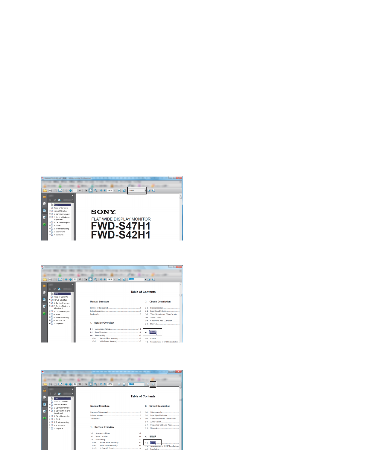
Search Function
m
. The following shows the example when using Adobe Reader 8.
. If you cannot fi nd the search function, select Edit → Search from the pull-down menu.
A function, menu, and command are searched using a service/protocol manual.
1. Open a fi le, enter the words, to be searched, in the frame indicated by the arrow on the screen below, and press the
[Enter] key.
2. Search the corresponding words in a document fi le.
3. Click the button in the enclosed portion.
Search the corresponding place.
GXD-L52H1
Acrobat, Acrobat Readeri is a trademark of Adobe Systems Incorporated in the
United States and/or other countries
3
Page 6

Page 7
1-1. Communication Parameters
Communication method RS-232C
Synchronous method Asynchronous
Baud rate 9600bps
Character length 8bit
Parity None
Start bit length 1bit
Stop bit length 1bit
Flow control None
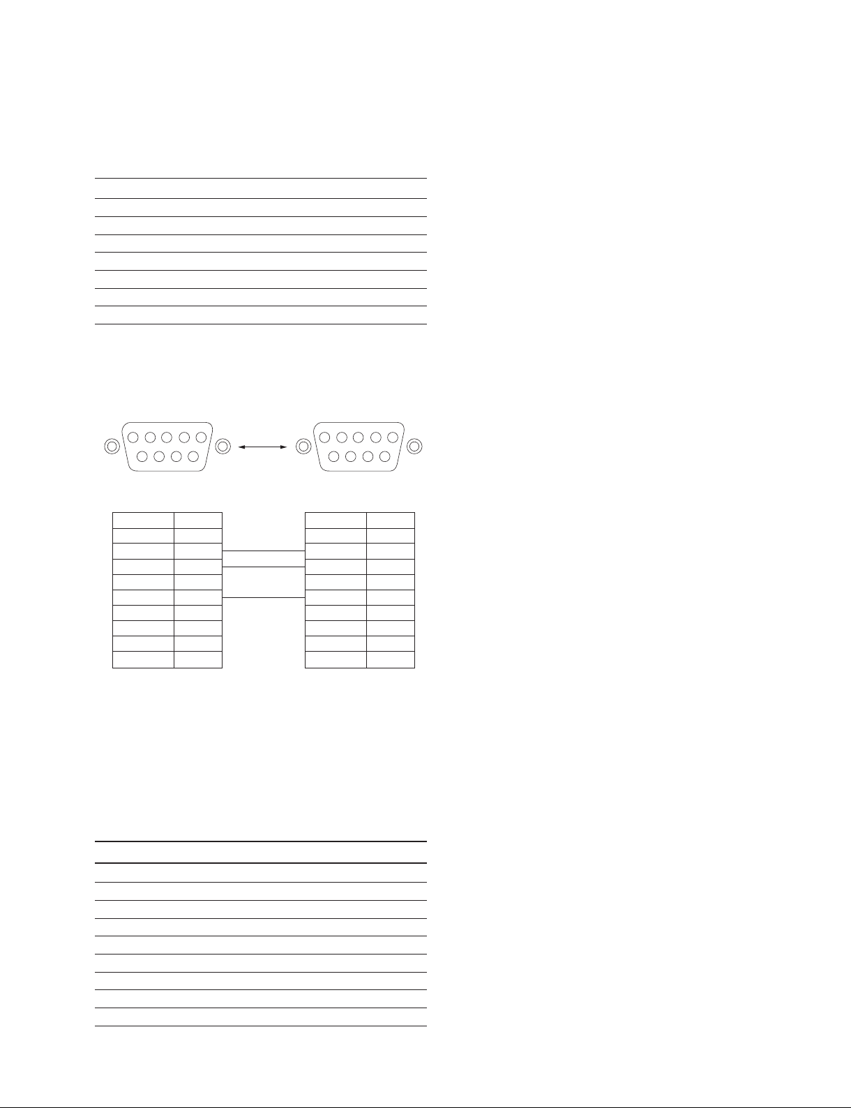
1-2. Pin Assignment
Section 1
RS-232C
Monitor side (D-sub 9-pin)
12345
6789
_ External view _
Pin No. Function
1 NC
2 TXD
3 RXD
4 NC
5 GND
6 NC
7 NC
8 NC
9 NC
Host side (D-sub 9-pin)
_ External view _
Pin No. Function
1 NC
2 RXD
3 TXD
4 NC
5 GND
6 NC
7 NC
8 NC
9 NC
n
Use the RS-232C straight cable.
1-3. Communication Data Format
12345
6789
(a) Control message
No. Item Value
1 Header 0x8C: Control
2 Category 0xXX
3 Function 0xXX
4 Data1 (Length) 0xXX
5 Data2 (Data1) 0xXX
: : 0xXX
: : 0xXX
X DataX 0xXX
X+1 Check Sum 0xXX
* Check Sum: Sum total of 1 to X. Lower one-byte data is validated when a value exceeds 255 (1byte).
GXD-L52H1
1-1
Page 8

(b) Enquiry message
No. Item Value
1 Header 0x83: Enquiry
2 Category 0xXX
3 Function 0xXX
4 Data1 0xFF
5 Data2 0xFF
6 Check Sum 0xXX
* Check Sum: Sum total of 1 to X, lower one-byte data is validated when a value exceeds 255 (1byte).
(c) Answer message
Control answer
No. Item Value
1 Header 0x70: Answer
2 Answer
0x01: Limit Over
0x02: Limit Under
0x03: Command Canceled
3 Check Sum 0xXX
* 0x00: Completed Packet is correctly received and process is also correctly completed.
0x01: Limit Over Packet is correctly received, but the data value is over the upper limit.
0x02: Limit Under Packet is correctly received, but the data value under the lower limit.
0x03: Command Canceled Packet is correctly received, but the data value is not correct. The request cannot be accepted in the current host state.
*
0x00: Completed
* Check Sum: Sum total of 1 to X, lower one-byte data is validated when a value exceeds 255 (1byte).
Enquiry answer (Complete)
No. Item Value
1 Header 0x70: Answer
2 Answer 0x00: Completed
3 Return Data Size 0xXX
4 Return Data1 0xXX
: : 0xXX
: : 0xXX
X Return DataX 0xXX
X+1 Check Sum 0xXX
* 0x00: Completed Packet is correctly received and process is also correctly completed.
* Return Data: Returns the read value.
* Check Sum: Sum total of 1 to X, lower one-byte data is validated when a value exceeds 255 (1byte).
Enquiry answer (Command cancel)
No. Item Value
1 Header 0x70: Answer
2 Answer 0x03: Command Canceled
3 Check Sum 0x73
0x03: Command Canceled Packet is correctly received, but the data value is not correct. The request cannot be accepted in the current host state.
1-2
GXD-L52H1
Page 9

Error answer
No. Item Value
1 Header 0xE0: Answer
2 Answer
0x01: Check Sum Error
0x02: Data Length Error
3 Check Sum 0xXX
* 0x00: No Function Error Packet header, category or function code are not included in this protocol.
0x01: Check Sum Error Check sum value of received packet is not correct.
0x02: Data Length Error The data size of received packet is not correct.
*
0x00: No Function Error
1-4. Outline of Communication
A controller (PC) communicates with a display according to the communication data format. Communication is started by
issuing a command from the controller. Communication is terminated when the display sends return data (an answer message) to the controller after it receives the issued command.
It is inhibited that a controller sends multiple commands at a time.
Therefore, a controller cannot send other commands until return data is sent back from a display after it sends one command. The display sends return data after command processing is completed.
GXD-L52H1
1-3
Page 10

Page 11

Section 2
SNMP
2-1. SNMP
This unit installs SNMP (Simple Network Management Protocol). SNMP is a standard protocol for
network management that was standardized in IETF (Internet Engineer Task Force).
By using SNMP, the management information of equipment connected to a network can be gotten via a
network. The information of multiple equipment gotten using SNMP can also be unitarily managed by
using SNMP management software.
The equipment corresponding to SNMP has a “management information database” called MIB (Management Information Base) in the inside of equipment. In SNMP, the bidirectional communication of data
contained in MIB is realized between a “management system” and “management object system” that exist
in a network.
In MIB, there is the standard MIB prescribed by RFC. Especially, MIB-II is its representative MIB.
MIB-II was established to manage a network. MIB-II is installed in much network equipment such as a
PC, router, and switch as a standard feature. This unit installs this MIB-II.
Monitoring and monitored sides exist when equipment is monitored via a network using SNMP. The
monitoring side is called an “SNMP manager”. It is mainly constituted by the software of PC. For the
monitored side, a module called an “SNMP agent” is installed. SNMP-compatible equipment transmits
MIB information to an SNMP manager via this SNMP agent. This unit installs this SNMP agent. This
unit can realize the communication with a general-purpose SNMP manager using this SNMP agent.
Basically, an SNMP agent replies only when an inquiry is sent from an SNMP manager.
The SNMP manager periodically inquires the equipment, which it manages, about MIB information. This
way to get information is called “polling”. In polling, equipment replies using a response command when
an SNMP manger sends a request command to equipment. By polling, therefore, equipment can be
monitored without applying a high load to the equipment.
On the other hand, notifi cation can also be done from the equipment side to an SNMP manager. This noti-
fi cation is called a “trap”. Using this trap, when a serious trouble occurred in equipment, it can be notifi ed
to the SNMP manager in a short time.
This unit is compatible with the two polling and trap protocols described above. Equipment can be
effi ciently monitored using these protocols.
GXD-L52H1
2-1
Page 12
2-2. Specifi cations of SNMP Installation
The specifi cations of the SNMP agent installed in this unit are shown in below.
. SNMP version: SNMPv1
. MIB defi nition: SMIv2
. Support PDU: GetRequesat
SetRequest
GetNextRequest
Trap
. Standard MIB to be installed: MIB-II
2-3. Installation
The setting below is required to use the SNMP function of this unit. (Set according to your network
environment and SNMP management environment.)
. Community and its Community property
. Authentication trap
. Host restriction
The Web server function of this unit is used for setting. Refer to the Operation Manual of this unit for the
operation of the Web server.
The contents of each item and the setting of SNMP are fully described in this specifi cation.
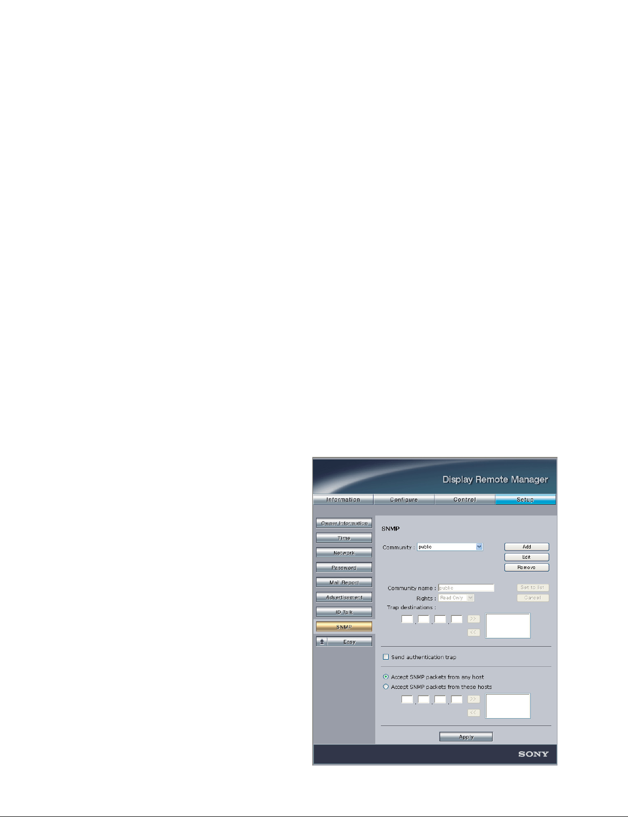
2-4. Operation of SNMP Setting Window
This section describes the procedure and contents for
setting of SNMP.
Open the Web page of this unit and click the [SNMP]
button in the Advanced setting item on the Setup page
(where an administrator’s password is necessary). The
SNMP setting window is displayed.
. User name: root
. Password: pudadm
\
2-2
SNMP Setting window (on Web Page)
GXD-L52H1
Page 13

2-4-1. Community
A Community name is used as the password for SNMP access. The request received from an SNMP manager is accepted when the Community name contained in the request coincides with the Community name
set. The request is rejected when the former does not coincide with the latter.
A maximum of three Communities can be set.
There are “Rights” and “Trap destinations” items in the property of Community. The property can be set
for each set Community.
n
When multiple Communities are set, all set Communities are validated.
1. Rights
The rights that can be set are as follows:
Read Only: An SNMP manager can reference MIB information using this Community name.
Read Write: This Community must be set when a write request is sent from an SNMP manager.
Other: Do not set this option because it is used for the function extension in future.
2. Trap destinations
When Trap destinations are set, during trap occurrence, a trap is notifi ed to the equipment set as trap desti-
nations using the Community name set.
Up to four Trap destinations can be set to one Community.
Trap destinations are not set in default.
n
This product can be set on only the Web screen because it does not install the automatic setting function
of Trap destinations.
3. Setting procedure of Community
Community can be added, edited, and removed.
The addition, editing, and removal procedures of Community are described below.
Addition of Community
1. Click the [Add] button.
The “Community name”, “Rights”, and “Trap destinations” text boxes, and [Set|to|List] and
[Cancel] buttons are validated.
2. Type the Community name you want to add.
3. Set the Rights of Community and the Trap destinations you want to add.
When you want to save the setting, click the [Set|to|List] button and then click the [Apply] button at
the bottom of the window.
m
. Click the [Cancel] button when you want to discard the setting during setting.
. When you want to save setting, be sure to click the [Set|to|List] button and then click the [Apply]
button.
GXD-L52H1
2-3
Page 14

Editing of Community
1. Select the Community, you want to edit, from a drop-down list.
2. Click the [Edit] button.
The “Community name”, “Rights”, and “Trap destinations” text boxes, and [Set|To|List] and
[Cancel] buttons are validated.
Edit the Community name when you want to edit a Community name.
3. Set the Rights of Community and the Trap destinations you want to edit.
m
. Click the [Cancel] button when you want to discard the setting during setting.
. When you want to save the setting, click the [Set|to|List] button and then click the [Apply] button
at the bottom of the window.
Removal of Community
1. Select the Community, you want to remove, from a drop-down list.
2. Click the [Remove] button and then click the [Apply] button at the bottom of the window.
n
Be sure to click the [Remove] button and then click the [Apply] button.
2-4-2. Authentication Trap
An authentication trap is the trap for making it detect by an SNMP manager that an illegal access was
gained to this unit using an SNMP protocol.
. The authentication trap is validated when this check box is selected. A trap is transmitted when an
illegal access is gained.
. The authentication trap is invalidated when this check box is not selected. A trap is not transmitted even
if an illegal access is gained.
n
Be sure to click the [Apply] button when you edited setting.
2-4-3. IP Restriction of Host
It is possible to put restrictions on the IP address of an SNMP manager, as one of the security countermeasures, which communicates using an SNMP protocol.
. IP address restriction is invalidated when you select “Accept packets from any host”.
. Only the SNMP access from an SNMP manager that has the set IP address is accepted when you select
“Accept packets from those hosts”. The SNMP access from an IP address that has not been set is rejected.
m
. Up to four IP restrictions can be set.
. Be sure to click the [Apply] button when you edited setting.
2-4
GXD-L52H1
Page 15

2-5. MIB to Be Installed
This unit installs MIB-II.
MIB-II is the most representative standard MIB. It is installed in various network products.
The statistical information on the amount of network traffi c or the number of transmitted and received
packets is defi ned, and the change or transition can be monitored by polling the information periodically.
Additionally, the management items to be installed can be defi ned using a TCP/IP device so as to get the
information effective for the monitoring of the network communication state.
Refer to RFC1213 for the detailed defi nition of MIB-II.
2-6. Information to Be Notifi ed on Trap
In software version 2.0 or later, the software have a function that transmits error information to this unit.
The error trap and authentication trap are installed.
GXD-L52H1
2-5
Page 16

Page 17

Section 3
ID Talk
ID Talk is set as described below. ID Talk is a protocol for operating the function of this unit via a network.
3-1. Default Setting
Item Description
Transport TCP
Port number 53484 (Factory setting)
TCP connection time-out 30 seconds (Factory setting)
3-2. Setting Items
The items that can be set to ID Talk are shown in the table below.
Item Description
Start ID Talk Service Select the check box when using ID Talk. Clear the check box when using no ID Talk.
(default setting: OFF)
Port No. Changes the port number. A port number have to change port number 53484 cannot
be used because it has been already used for another purpose.
Timeout Specify the timeout time of connection.
Connection is automatically disconnected when communication is not done for the
specifi ed time.
IP address of client Executes only the request from the specifi ed IP address.
(Host Address) ID Talk does not have the security function such as user authentication. During
installation, safety can be improved by setting this item.
Multiple host addresses can be set.
Community Changes the community of a header. Four (upper-or-lower case) alphanumeric
characters can be set.
(default setting: SONY)
Set the items described above properly on the SETUP → ID Talk page of the Web page when using ID
Talk.
Enter the SETUP page using the user name and password below.
. User name: root
. Password: pudadm
GXD-L52H1
3-1
Page 18
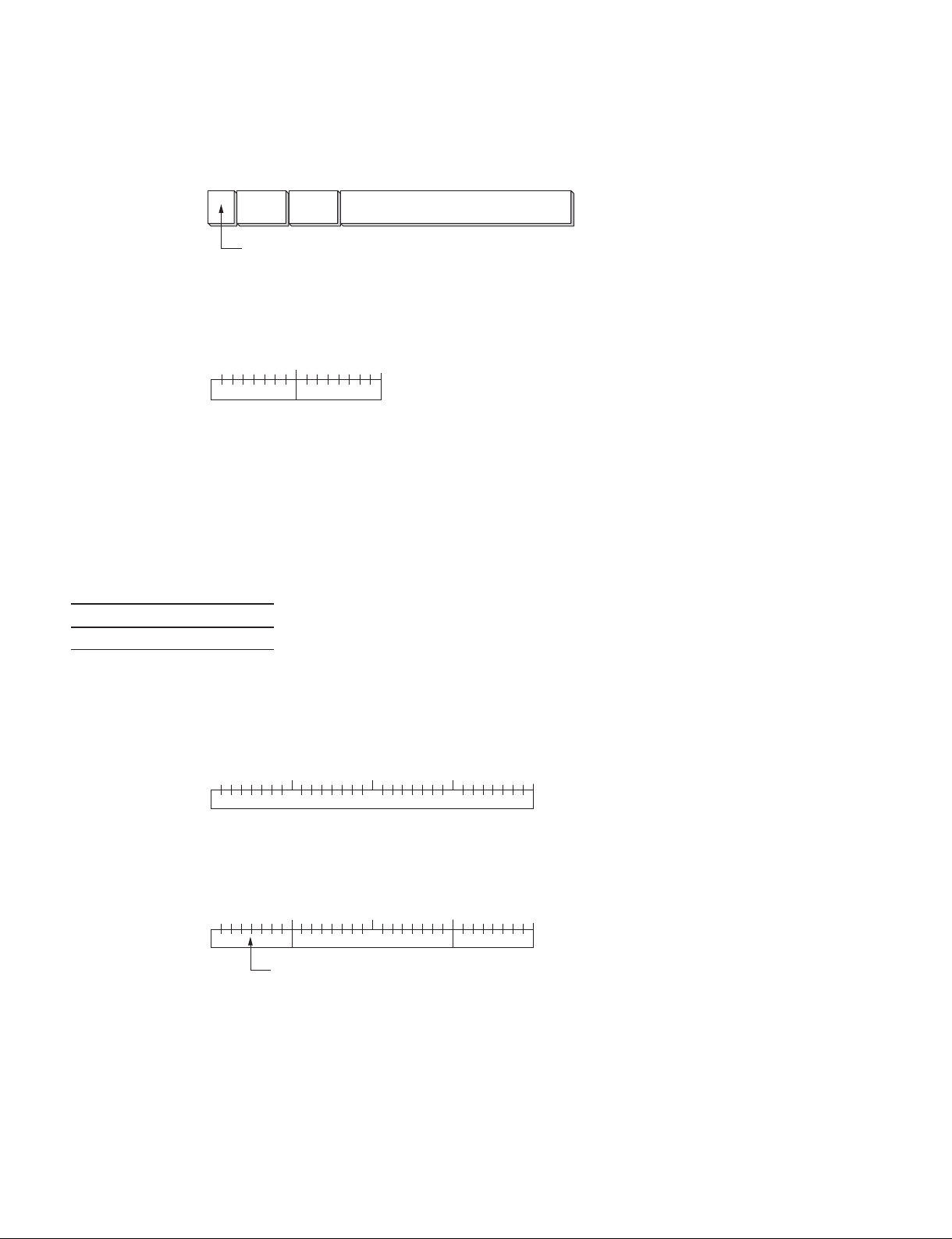
3-3. Packet Structure
The packet structure of ID Talk is described below.
Community
(4)
Header
(2)
Command
(4)
Data
(n)
Packet structure
1. Header
The header is constituted by two bytes consisting of a version (8 bits) and category (8 bits).
0
0
1 2 3 4 5 6 7 8 9 0 1 2 3 4 5
Version (8) Category (8)
1 (Bit position)
Header structure
Version
Indicates the version number of an ID Talk protocol.
This version is fi xed to 02h (version 2).
Category
Contains the category number of display equipment to be controlled. A category number is confi rmed on
the display equipment side. A request is ignored when a different category number is contained.
Code Category
10h Information Display
2. Community
A request is executed when community coincides with the community set in display equipment. Community consists of four (upper- or lower-case) alphanumeric characters. “SONY” is a factory-setting value.
The set character can be changed on the Web page.
0
0
1 2 3 4 5 6 7 8 9 0 1 2 3 4 5 6
1
Community (32)
23
7 8 9 0 1 2 3 4 5 6 7 8 9 0 1
Community packet
(Bit position)
3. Command
The format of a request packet and response packet is described below.
0
0
1 2 3 4 5 6 7 8 9 0 1 2 3 4 5 6
1
Request/Response(8)
23
7 8 9 0 1 2 3 4 5 6 7 8 9 0 1
Item No(16) Data Length(8)
Command packet
(Bit position)
3-2
GXD-L52H1
Page 19

4. Request
The format when sending a request from a host to display equipment is described below.
Community
This is the same alphanumeric character as the community set in display equipment that sends a request.
Request
This is a request for display equipment.
Item No.
This is the item number to be treated for request.
Data Length
This is the length of data incident to a request. The maximum length is 128 bytes. The length of data is
“0” when no data exists.
Data
This is data incident to a request.
5. Response
The format when display equipment returns a response to the request from a host is described below.
Community
This contains the same alphanumeric character as a request. For a short header and short community, this
is embedded with 00h.
Response
This contains the result of a request.
Item No.
This is the item number to be treated for response.
Data Length
This is the length of data incident to a response. The maximum length is 128 bytes. The length of data is
“0” when no data exists.
Data
This is data incident to a response.
3-4. Requests and Responses
Requests and responses are described below.
1. Requests
Requests are only a GET request that gets the display information or state and a SET request that changes
the setting of display equipment.
Request Contents
SET (00h) Writes data in the register of display equipment.
GET (01h) Gets the installation information, equipment state, or setting values.
SET command:
Communication with the main microcomputer of display equipment can be done via a network by using
the protocol dedicated to this unit as well as an ID Talk protocol. Use a SET command in this case. (Also,
use a SET command when receiving information from the display equipment.)
GXD-L52H1
3-3
Page 20

2. Responses
A response returns the result of execution to the request from a host.
Response Contents
NG (00h) Indicates that a request is invalid or could not be executed.
OK (01h) Indicates that a request could be executed normally.
3. SET request
The SET request sets a new value to the specifi ed item. A request and its response are described in details
below.
Request
Request Item No. Data
Response
Response to SET request
Data
Length
SET request
Set Data(n byte)00h Item No. n
Get Data(n byte)OK(01h) Item No. n
4. GET request
The GET request gets the value of the specifi ed item. A request and its response are described in details
below.
Request
Request Item No.
01h Item No. 0
Response
Response to GET request
Data
Length
GET request
Get Data(n byte)OK(01h) Item No. n
5. ERROR response
An NG message is returned as a response when an error occurs in the contents of a request or the result of
execution.
Error Code(16)NG(00h) Item No. 2
ERROR response
3-5. Items
Category Contents SET GET
80**h Gets the information of this unit O O
90**h Gets the network setting information. _ O
F100h FWD-S42H1/S47H1 dedicated protocol O _
3-4
GXD-L52H1
Page 21

1. 80**h
This item gets the information of the connected display equipment.
Lower byte Contents SET GET
00h Category Code _ O
01h Model Name _ O
02h Serial Number _ O
03h Installation Place O O
0x8000 Category code
1 byte
0x8001 Model name
12 alphanumeric characters
For under 12 alphanumeric characters, the remaining section is set as 00h.
0x8002 Serial number
4 bytes
0x8003 Installation place
24 alphanumeric characters
For under 24 alphanumeric characters, the remaining section is set as 00h.
2. 90**h
This item gets the network setting information.
Lower byte Contents SET GET
00h MAC Address _ O
01h IP Address _ O
02h Subnet Mask _ O
03h Default Gateway _ O
04h DHCP _ O
0x9000 MAC Address
6 bytes
0x9001 IP Address
4 bytes
0x9002 Subnet Mask
4 bytes
0x9003 Default Gateway
4 bytes
0x9004 DHCP
1 byte
DHCP invalid data value: 0
DHCP valid data value: 1
3. F100h
This unit dedicated protocol packets can be transmitted to the main microcomputer of this unit as ID Talk
data according to this unit dedicated protocol. The response of protocol is returned as the data of ID Talk
response packets.
GXD-L52H1
3-5
Page 22

3-6. Error Codes
An error code list and its details are shown in the table below.
Category Error Error code
Item Error (01**h) Invalid Item 01h
Invalid Item Request 02h
Invalid Length 03h
Invalid Data 04h
Short Data 11h
Not Applicable Item 80h
Community Error (02**h) Different Community 01h
Request Error (10**h) Invalid Version 01h
Invalid Category 02h
Invalid Request 03h
Short Header 11h
Short Community 12h
Short Command 13h
Network Error (20**h) Timeout 01h
Comm Error (F0**h) Timeout 01h
Check Sum Error 10h
Framing Error 20h
Parity Error 30h
Over Run Error 40h
Other Comm Error 50h
Unknown Response F0h
NVRAM Error (F1**h) Read Error 10h
Write Error 20h
1. Item errors
An item error occurs when the Item No. or Data of a request is invalid. The conditions under which each
error occurs are described below.
Invalid Item
When Item No. that is not supported is specifi ed
Invalid Item Request
When Item No. is supported, but Request that is not supported is requested
Invalid Length
When the Data Length of the specifi ed Item No. is too long
Invalid Data
When the Data of the specifi ed Item No. differs in the setting range
Short Data
When the length of data differs from the value specifi ed using Data Length
Not Applicable Item
When an item that is not valid at present is specifi ed
2. Community error
This error occurs when community differs.
3-6
GXD-L52H1
Page 23

3. Request errors
These errors occur when a header or command is invalid. The conditions under which each error occurs
are described below.
Invalid Version
When the version of a header is other than 2
Invalid Category
When a category differs
Invalid Request
When a request that is not supported is specifi ed
Short Header
When the received data is 1 byte
Short Community
When the received data is 2 to 5 bytes
Short Command
When the received data is 6 to 9 bytes
4. Network error
This error occurs in TCP/IP. The conditions under which an error occurs are described below.
Timeout
When communication was interrupted halfway
5. Comm error
This is an error that occurs during communication with the main control microcomputer of display equipment.
Timeout
When the received data is not sent after data transmission
Check Sum Error
When a check sum error occurs in the main control microcomputer
Framing Error
When a framing error occurs
Parity Error
When a parity error occurs
Over Run Error
When an overrun error occurs
Other Comm Error
When other errors occur
Unknown Response
When data that cannot be processed is received
6. NVRAM error
Read Error
When the read operation from NVRAM fails
Write Error
When the write operation to NVRAM fails
GXD-L52H1
3-7
Page 24

Simultaneous processing is not performed when one unit is controlled from multiple hosts via a network
in Section 1.
A cancel command is returned to connection when access is gained from another host during processing
of one command.
(0x02 0x10 0x53 0x4F 0x4E 0x59 0x00 0xF1 0x00 0x03 0x70 0x03 0x73)
3-8
GXD-L52H1
Page 25

Appendix 1
Command Examples
RS232 Command Examples
(1) Power On
Header Category Function Data1 Data2 Check Sum
Command 0x8C 0x00 0x00 0x02 0x01 0x8F
Control Mode Control Power FIX ON = 0x8C + 0x00 + 0x00 + 0x02 +
Header Answer Check Sum
Answer 0x70 0x00 0x70 : When a command is completed
Control Complete
Header Answer Check Sum
0x70 0x03 0x73 : When a command is canceled
Control Command
Canceled
0x01
(2) INPUT SELECT HD15 RGB
Header Category Function Data1 Data2 Check Sum
Command 0x8C 0x00 0x01 0x02 0x08 0x97
Control Mode Control Input Select FIX HD15 RGB = 0x8C + 0x00 + 0x01 + 0x02 +
0x08
Header Answer Check Sum
Answer 0x70 0x00 0x70 : When a command is completed
Control Complete
(3) MULTI DISPLAY BATCH
Header Category Function Data1 Data2 Data3 Data4
Command 0x8C 0x20 0x11 0x08 0x01 0x03 0x00
Control Size/Shift Mullti Display
Batch
Data5 Data6 Data7 Data8 Check Sum
0x1E 0x1E 0x1E 0x1E 0x41
H Size H Shift V Size V Shift = 0x8C + 0x20 + 0x11 + 0x08 + 0x01 + 0x03 +
Arbitrary numbers in the range of 0x00 (minimum) to 0x3C
(maximum)
FIX 2 x 2 Position 4 Tiles
0x00 + 0x1E + 0x1E + 0x1E + 0x1E = 0x141
* Lower one-byte data “41” is validated because
the sum total exceeds 255 (0xFF).
Header Answer Check Sum
Answer 0x70 0x00 0x70 : When a command is completed
Control Complete
GXD-L52H1
Set to position 4 by multi-display 2 x 2.
12
34
A1-1
Page 26

ID Talk Command Examples
(1) Power On
Header Community Request/
Response
Command 0x02 0x10 0x53 0x4F 0x4E 0x59 0x00 0xF1 0x00
FIX
(Version)
Data
Length
0x06 0x8C 0x00 0x00 0x02 0x01 0x8F
Data length
after the
above.
Header Community Request/
Answer 0x02 0x10 0x53 0x4F 0x4E 0x59 0x00 0xF1 0x00
FIX
(Version)
Data
Length
0x03 0x70 0x00 0x70 : When a command is completed
Data length
after the
above.
FIX
(Category)
Header Category Function Data1 Data2 Check Sum
Control Mode
FIX
(Category)
Header Answer Check
Control Complete
FIX
(S)
Control
FIX
(S)
FIX
(O)
Power Data
FIX
(O)
Sum
FIX
(N)
length
after the
above.
FIX
(N)
FIX
(Y)
ON = 0x8C + 0x00 + 0x00 + 0x02 + 0x01
FIX
(Y)
Set FIX FIX
Response
Set FIX FIX
Item No
Item No
Header Community Request/
Response
0x02 0x10 0x53 0x4F 0x4E 0x59 0x00 0xF1 0x00
FIX
(Version)
Data
Length
0x03 0x70 0x03 0x73 : When a command is canceled
Data length
after the
above.
FIX
(Category)
Header Answer Check
Control Command
FIX
(S)
Canceled
FIX
(O)
Sum
FIX
(N)
FIX
(Y)
Set FIX FIX
Item No
A1-2
GXD-L52H1
Page 27

(2) INPUT SELECT HD15 RGB
Header Community Request/
Response
Command 0x02 0x10 0x53 0x4F 0x4E 0x59 0x00 0xF1 0x00
FIX
(Version)
Data
Length
0x06 0x8C 0x00 0x01 0x02 0x08 0x97
Data length
after the
above.
Header Community Request/
Answer 0x02 0x10 0x53 0x4F 0x4E 0x59 0x00 0xF1 0x00
FIX
(Version)
Data
Length
0x03 0x70 0x00 0x70 : When a command is completed
Data length
after the
above.
FIX
(Category)
Header Category Function Data1 Data2 Check Sum
Control Mode
FIX
(Category)
Header Answer Check
Control Complete
FIX
(S)
Control
FIX
(S)
FIX
(O)
Input
Select
FIX
(O)
Sum
FIX
(N)
Data
length
after the
above.
FIX
(N)
FIX
(Y)
HD15
RGB
FIX
(Y)
Set FIX FIX
= 0x8C + 0x00 + 0x01 + 0x02 + 0x08
Response
Set FIX FIX
Item No
Item No
GXD-L52H1
A1-3
Page 28

(3) MULTI DISPLAY BATCH
Header Community Request/
Response
Command 0x02 0x10 0x53 0x4F 0x4E 0x59 0x00 0xF1 0x00
FIX
(Version)
Data
Length
0x0C 0x8C 0x20 0x11 0x08 0x01 0x03 0x00
Data length
after the
above.
Data5 Data6 Data7 Data8 Check
0x1E 0x1E 0x1E 0x1E 0x41
H Size H Shift V Size V Shift = 0x8C + 0x20 + 0x11 + 0x08 + 0x01 + 0x03 + 0x00 + 0x1E +
Arbitrary numbers in the range of 0x00 (minimum) to
0x3C (maximum)
FIX
(Category)
Header Category Function Data1 Data2 Data3 Data4
Control Size/Shift Mullti
FIX
(S)
FIX
(O)
Display
Batch
FIX
(N)
Data
length
after the
above.
Sum
0x1E + 0x1E + 0x1E = 0x141
* Lower one-byte data “41” is validated because the sum total
exceeds 255 (0xFF).
Set to position 4 by multi-display 2 x 2.
12
FIX
(Y)
2 x 2 Position 4 Tiles
Set FIX
Item No
34
Header Community Request/
Response
Answer 0x02 0x10 0x53 0x4F 0x4E 0x59 0x00 0xF1 0x00
FIX
(Version)
Data
Length
0x03 0x70 0x00 0x70 : When a command is completed
Data length
after the
above.
FIX
(Category)
Header Answer Check
Control Complete
FIX
(S)
FIX
(O)
Sum
FIX
(N)
FIX
(Y)
Set FIX FIX
Item No
A1-4
GXD-L52H1
Page 29

Appendix 2
Common Command
n The item, in a table, described below varies depending on the model used.
Example) (Refer to Appendix 3 “General information”.)
Check the reference and make necessary changes according to the model to be used.
1. General Function
(a) Mode Control
Syntax Header Category Function Data1 Data2 Check Sum
Control 0x8C 0x00 Code Table(1-a)[a] 0x02 Code Table (1-a)[b] 0xXX
Enquiry 0x83 0xFF 0xFF 0xXX
Answer Header Answer Check Sum
Control 0x70 0x00 0x70 Completed
0x70 0x01 0x71 Limit Over
0x70 0x02 0x72 Limit Under
0x70 0x03 0x73 Command Canceled
Answer Header Answer Return to Data Size Return Data1 Check Sum
Enquiry 0x70 0x00 0x02 Code Table (1-a)[b] 0xXX Completed
Code Table(1-a)
[a]Function [b]Range/Switch Code Command
Control Enquiry Standby Power On
0x00 Power 0x00 OFF Yes Yes Enable Enable
0x01 ON
0x01 Input Select
0x02 Force Status Display 0x00 ON Yes Yes Disable Enable
0x01 OFF
0x03 Audio Mute 0x00 OFF Yes Yes Disable Enable
0x01 ON
0x04 Auto Status Display 0x00 ON Yes Yes Enable Enable
0x01 OFF
0x06 Color System 0x00 Auto Yes Yes Disable Enable
0x01 NTSC
0x02 NTSC4.43
0x03 PAL
0x05 PAL-M
0x06 PAL-N
0x07 PAL60
0x0F Language 0x00 Japanese Yes Yes Disable Enable
0x01 English
0x02 Deutsch
0x03 Français
0x04 Español
0x05 Italiano
0x10 Index Number 0x01-0xFF Yes Yes Disable Enable
*1
(Refer to Appendix 3 “General Function”.)
(Continued)
GXD-L52H1
A2-1
Page 30

Code Table(1-a)
[a]Function [b]Range/Switch Code Command
Control Enquiry Standby Power On
0x12 Standby Power 0x00 Standard Yes Yes Disable Enable
0x01 Low
0x13 ECO Mode 0x00 Off Yes Yes Disable Enable
(Power Saving) 0x01 ECO High
0x02 ECO Low
0x14 Speaker Out 0x00 ON Yes Yes Disable Enable
0x01 OFF
0x18 Sync Mode 0x00 H/Comp Yes Yes Disable Enable
0x01 Video
0x1B Clock Display 0x00 OFF Yes Yes Disable Enable
0x01 ON
0x1D Color Matrix (Refer to Appendix 3 “General Function”.)
FWD-S42H1/S47H1 and GXD-L65H1 are not used this command.
0x22 Time Set H: 0x00-0x17, M: 0x00-0x3B
(Hour, minute)
0x23 Time Set (Week) (Refer to Appendix 3 “General Function”.)
0x24 Input Detect(Option) (Refer to Appendix 3 “General Function”.)
FWD-S42H1/S47H1 and GXD-L65H1 are not used this command.
0x26 Auto Shut OFF 0x00 OFF Yes Yes Disable Enable
0x01 ON
0x27 Auto Screen Adjust 0x00 OFF Yes Yes Disable Enable
0x01 ON
0x30 PAP 0x00 OFF Yes Yes Disable Enable
0x01 P&P
0x02 PinP
0x31 Active Picture 0x00 Left(P&P)/Main(PinP) Yes Yes Disable Enable
0x01 Right (P&P)/Sub (PinP)
0x02 Swap
0x32 Picture Size(P&P) 0x00-0x0E Yes Yes Disable Enable
0x33 Sub Picture Size 0x00 Large Yes Yes Disable Enable
(PinP) 0x01 Small
0x34 Picture Position 0x00 Position1 Yes Yes Disable Enable
(PinP) 0x01 Position2
0x02 Position3
0x03 Position4
0x35 PAP Input Detect (Refer to Appendix 3 “General Function”.)
(Left/Main)
0x36 PAP Input Detect (Refer to Appendix 3 “General Function”.)
(Right/Sub)
0x40 Screen Saver (Refer to Appendix 3 “General Function”.)
0x43 BackLight 0x00-0x64 Yes Yes Disable Enable
0x44 Logo Illumination & 0x00 Logo Off Yes Yes Enable Enable
Status LED 0x01 Logo On (Low)
0x02 Logo On (High)
0x45 Control Mode 0x00 Main+Remocon Yes Yes Disable Enable
0x01 Main
0x02 Remocon
0x03 All Off
(Continued)
A2-2
GXD-L52H1
Page 31

Code Table(1-a)
[a]Function [b]Range/Switch Code Command
Control Enquiry Standby Power On
0x47 On Timer Enable bit0 Sunday 1: Enable, 0: Disable Yes Yes Enable Enable
bit1 Monday 1: Enable, 0: Disable
bit2 Tuesday 1: Enable, 0: Disable
bit3 Wednesday 1: Enable, 0: Disable
bit4 Thursday 1: Enable, 0: Disable
bit5 Friday 1: Enable, 0: Disable
bit6 Saturday 1: Enable, 0: Disable
bit7 Every day 1: Enable, 0: Disable
0x48 Off Timer Enable bit0 Sunday 1: Enable, 0: Disable Yes Yes Enable Enable
bit1 Monday 1: Enable, 0: Disable
bit2 Tuesday 1: Enable, 0: Disable
bit3 Wednesday 1: Enable, 0: Disable
bit4 Thursday 1: Enable, 0: Disable
bit5 Friday 1: Enable, 0: Disable
bit6 Saturday 1: Enable, 0: Disable
bit7 Every day 1: Enable, 0: Disable
0x65 IP Setting Mode 0x00 DHCP Yes Yes Enable Enable
0x01 Manual
0x02 Speed
0x68 Speed Setting 0x00 100Mbps/Full Duplex Yes Yes Enable Enable
0x01 100Mbps/Half Duplex
0x02 10Mbps/Full Duplex
0x03 10Mbps/Half Duplex
0x04 Auto
0x70 Input Skip (Refer to Appendix 3 “General Function”.)
0x71 Default Input 0x00 Last Memory Yes Yes Enable Enable
0x01 Option1
0x74 Digital Signal Detect 0x00 VIDEO No Yes Disable Enable
*2
(DVI/HDMI/etc.)
0x75 Signal Status
0x01 PC
*3
0x00 Stable No Yes Disable Enable
0x01 Unstable/No Signal
0x76 VIDEO Signal Detect 0x00 NTSC No Yes Disable Enable
0x01 PAL
0x77 Priority Level of (Refer to Appendix 3 “General Function”.)
Signal select
GXD-L52H1 and FWD-S42H1/S47H1 are used for only Enquiry.
0x7A Logo Position 0x00 Auto Yes Yes Enable Enable
0x01 Landscape
0X02 Portrait
0x7D Power Management 0x00 OFF Yes Yes Disable Enable
*4
Mode
0x01 ON
0x7E On Screen Logo 0x00 OFF Yes Yes Enable Enable
0x01 ON (Default)
0x7F LED 0x00 OFF Yes Yes Disable Enable
0x01 ON
0x80 Standby Screen (Refer to Appendix 3 “General Function”.
Saver Time
GXD-L52H1 is not used this command.
(Continued)
GXD-L52H1
A2-3
Page 32

Code Table(1-a)
[a]Function [b]Range/Switch Code Command
Control Enquiry Standby Power On
0x81 Power On Delay (Refer to Appendix 3 “General Function”.)
GXD-L52H1 is not used this command.
0x82 Audio Delay (Refer to Appendix 3 “General Function”.)
GXD-L52H1 is not used this command.
0x83 IP Address (Player) (Refer to Appendix 3 “General Function”.)
GXD-L52H1 is not used this command.
0x85 Power On Batch (Refer to Appendix 3 “General Function”.)
GXD-L52H1 is not used this command.
0x86 HD15 Out (Refer to Appendix 3 “General Function”.)
GXD-L52H1 is not used this command.
0x89 Light Sensor (Refer to Appendix 3 “General Function”.)
GXD-L52H1 and FWD-S42H1/S47H1 are not used this command.
0x8A RGB Signal (Refer to Appendix 3 “General Function”.)
GXD-L52H1 and FWD-S42H1/S47H1 are not used this command.
0x8B Warm Up Mode (Refer to Appendix 3 “General Function”.)
GXD-L52H1 and FWD-S42H1/S47H1 are not used this command.
0x8C Warm Up Time (Refer to Appendix 3 “General Function”.)
GXD-L52H1 and FWD-S42H1/S47H1 are not used this command.
0x8D Picture Mute (Refer to Appendix 3 “General Function”.)
*1: Auto Signal Detect becomes Disable. When Option Slot is connected, Option command is Enable.
*2: Digital Signal Status is Enable for Digital Input Signal Detect Function only in Stable.
*3: Digital Signal or VIDEO Signal is Enable. Return Signal Status of Active Window.
*4: Only the panel power supply is turned off at the standby when setting it “ON”.
2. Analog Signal Detect Function
(a) Mode Control
Syntax Header Category Function Data1 Data2 Check Sum
Enquiry 0x83 0x00 Code Table (1-a) [a] Code Table (1-d) 0xFF 0xXX
Answer Header Answer Return to Data Size Return Data1 Data2 Check Sum
Enquiry 0x70 0x00 0x02 Code Table (1-a) [b] 0xFF 0xXX Completed
Code Table (1-a)
[a]Function [b]Range/Switch Code Command
Control Enquiry Standby Power On
0x78 Analog Signal Detect 0x00 VIDEO No Yes Disable Enable
0x01 PC
Code Table (1-d)
Input Select
0x00 Main
0x01 Sub
0xFF Present input
1-a[b]
When input is no signal or not supported signal, return value become
Video (0x00).
A2-4
GXD-L52H1
Page 33

3. Priority Signal Select Function
(a) Mode Control
(Refer to Appendix 3 “General Function”.)
4. RGB Signal
(a) Mode Control
(Refer to Appendix 3 “RGB Signal”.)
GXD-L52H1 and FWD-S42H1/S47H1 are not used this command.
(b) Time Control
Data Set (Month, Date)
Syntax Header Category Function Data1 Data2 Data3 Check Sum
Control 0x8C 0x00 0x7C 0x03 Month: 0x01-0x0C Date: 0x01-0x1F 0xXX
Syntax Header Category Function Data1 Data2 Check Sum
Enquiry 0x83 0x00 0x7C 0xFF 0xFF 0xFD
Answer Header Answer Check Sum
Control 0x70 0x00 0x70 Completed
0x70 0x01 0x71 Limit Over
0x70 0x02 0x72 Limit Under
0x70 0x03 0x73 Command Canceled
Answer Header Answer Return to Data Size Return Data1 Return Data2 Check Sum
Enquiry 0x70 0x00 0x03 Month: 0x00-0x0C Date: 0x01-0x1F 0xXX Completed
Year Set
Syntax Header Category Function Data1 Data2 Check Sum
Control 0x8C 0x00 0x7B 0x02 Year: 0x00-0x63 0xXX
Syntax Header Category Function Data1 Data2 Check Sum
Enquiry 0x83 0x00 0x7B 0xFF 0xFF 0xFC
Answer Header Answer Check Sum
Control 0x70 0x00 0x70 Completed
0x70 0x01 0x71 Limit Over
0x70 0x02 0x72 Limit Under
0x70 0x03 0x73 Command Canceled
Answer Header Answer Return to Data Size Return Data1 Check Sum
Enquiry 0x70 0x00 0x02 Year: 0x00-0x63 0xXX Completed
GXD-L52H1
A2-5
Page 34

Clock Set (Hour, Minute)
Syntax Header Category Function Data1 Data2 Data3 Check Sum
Control 0x8C 0x00 0x22 0x03 Hour: 0x00-0x17 Minute: 0x00-0x3B 0xXX
Syntax Header Category Function Data1 Data2 Check Sum
Enquiry 0x83 0x00 0x22 0xFF 0xFF 0xA3
Answer Header Answer Check Sum
Control 0x70 0x00 0x70 Completed
0x70 0x01 0x71 Limit Over
0x70 0x02 0x72 Limit Under
0x70 0x03 0x73 Command Canceled
Answer Header Answer Return to Data Size Return Data1 Return Data2 Check Sum
Enquiry 0x70 0x00 0x03 Hour: * Minute: 0x00-0x3B 0xXX Completed
0x00-0x17
Clock Set (Week)
Syntax Header Category Function Data1 Data2 Check Sum
Enquiry 0x83 0x00 0x23 0xFF 0xFF 0xA4
Answer Header Answer Return to Data Size Return Data1 Check Sum
Enquiry 0x70 0x00 0x02 Week: Code Table (1-e) 0xXX Completed
Code Table (1-e)
Week Select
0x00 Sunday
0x01 Monday
0x02 Tuesday
0x03 Wednesday
0x04 Thursday
0x05 Friday
0x06 Saturday
On Timer, Off Timer
Syntax Header Category Function Data1 Data2 Data3 Check Sum
Control 0x8C 0x00 Code Table (1-f) [a] 0x03 Hour: 0x00-0x17 Minute: 0x00-0x3B 0xXX
Syntax Header Category Function Data1 Data2 Check Sum
Enquiry 0x83 0x00 Code Table (1-f) [a] 0xFF 0xFF 0xXX
A2-6
GXD-L52H1
Page 35

Answer Header Answer Check Sum
Control 0x70 0x00 0x70 Completed
0x70 0x01 0x71 Limit Over
0x70 0x02 0x72 Limit Under
0x70 0x03 0x73 Command Canceled
Answer Header Answer Return to Data Size Return Data1 Return Data2 Check Sum
Enquiry 0x70 0x00 0x03 Hour: 0x00-0x17 Minute: 0x00-0x3B 0xXX Completed
Code Table (1-f)
[a]Function [b]Range/Switch Code Command
Control Enquiry Standby Power On
On Timer
0x50 Sunday _ Yes Yes Disable Enable
0x51 Monday _
0x52 Tuesday _
0x53 Wednesday _
0x54 Thursday _
0x55 Friday _
0x56 Saturday _
0x57 Every day _
Off Timer
0x58 Sunday _ Yes Yes Disable Enable
0x59 Monday _
0x5A Tuesday _
0x5B Wednesday _
0x5C Thursday _
0x5D Friday _
0x5E Saturday _
0x5F Every day _
GXD-L52H1
A2-7
Page 36

(c) IP Address Setting
IP Address
Syntax Header Category Function Data1 Data2 Data3 Data4 Data5 Check Sum
Control 0x8C 0x00 0x42 0x05 Address 0 Address 1 Address 2 Address 3 0xXX
0x00-0xFF 0x00-0xFF 0x00-0xFF 0x00-0xFF
Syntax Header Category Function Data1 Data2 Check Sum
Enquiry 0x83 0x00 0x42 FFh FFh 0xC3
Subnet Mask
Syntax Header Category Function Data1 Data2 Data3 Data4 Data5 Check Sum
Control 0x8C 0x00 0x61 0x05 Address 0 Address 1 Address 2 Address 3 0xXX
0x00-0xFF 0x00-0xFF 0x00-0xFF 0x00-0xFF
Syntax Header Category Function Data1 Data2 Check Sum
Enquiry 0x83 0x00 0x61 FFh FFh 0xE2
Gateway Address
Syntax Header Category Function Data1 Data2 Data3 Data4 Data5 Check Sum
Control 0x8C 0x00 0x62 0x05 Address 0 Address 1 Address 2 Address 3 0xXX
0x00-0xFF 0x00-0xFF 0x00-0xFF 0x00-0xFF
Syntax Header Category Function Data1 Data2 Check Sum
Enquiry 0x83 0x00 0x62 FFh FFh 0xE3
DNS Primary
Syntax Header Category Function Data1 Data2 Data3 Data4 Data5 Check Sum
Control 0x8C 0x00 0x63 0x05 Address 0 Address 1 Address 2 Address 3 0xXX
0x00-0xFF 0x00-0xFF 0x00-0xFF 0x00-0xFF
Syntax Header Category Function Data1 Data2 Check Sum
Enquiry 0x83 0x00 0x63 FFh FFh 0xE4
DNS Secondary
Syntax Header Category Function Data1 Data2 Data3 Data4 Data5 Check Sum
Control 0x8C 0x00 0x64 0x05 Address 0 Address 1 Address 2 Address 3 0xXX
0x00-0xFF 0x00-0xFF 0x00-0xFF 0x00-0xFF
Syntax Header Category Function Data1 Data2 Check Sum
Enquiry 0x83 0x00 0x64 FFh FFh 0xE5
A2-8
GXD-L52H1
Page 37

Player IP Address
Syntax Header Category Function Data1 Data2 Check Sum
Enquiry 0x83 0x00 0x83 FFh FFh 0x04
Answer Header Answer Check Sum
Control 0x70 0x00 0x70 Completed
0x70 0x03 0x73 Command Canceled
Answer Header Category Function Data1 Data2 Data3 Data4 Data5 Check Sum
Enquiry 0x8C 0x00 Code Table 0x05 Address 0 Address 1 Address 2 Address 3 0xXX
(1-a)[a] 0x00-0xFF 0x00-0xFF 0x00-0xFF 0x00-0xFF
IP Address ex)
192.128.14.1 → 192 (0xC0) Address 0
128 (0x80) Address 1
14 (0x0E) Address 2
1 (0x01) Address 3
* IP address command can be carried out even in the standby state.
Code Table (1-a)
[a]Function [b]Range/Switch Code Command
Control Enquiry Standby Power On
0x42 IP Address _ Enable Enable Enable Enable
0x61 Subnet Mask _
0x62 Gateway Address _
0x63 DNS Primary _
0x64 DNS Secondary _
0x83 IP Address (Player) _ Disable Enable Enable Enable
5. Picture/Sound
(a) Picture/Sound
Syntax Header Category Function Data1 Data2 Check Sum
Control 0x8C 0x10 Code Table (2-a) [a] 0x02 Code Table (2-a) [b] 0xXX
Enquiry 0x83 0xFF 0xFF 0xXX
Answer Header Answer Check Sum
Control 0x70 0x00 0x70 Completed
0x70 0x01 0x71 Limit Over
0x70 0x02 0x72 Limit Under
0x70 0x03 0x73 Command Canceled
Answer Header Answer Return to Data Size Return Data1 Check Sum
Enquiry 0x70 0x00 0x02 Code Table (2-a) [b] 0xXX Completed
GXD-L52H1
A2-9
Page 38

Code Table (2-a)
[a]Function [b]Range/Switch code Command
Control Enquiry Standby Power On
0x00 Contrast 0x00-0x64 Yes Yes Disable Enable
0x01 Brightness 0x00-0x64 Yes Yes Disable Enable
0x02 Chroma 0x00-0x32 Yes Yes Disable Enable
0x03 Phase 0x00-0x64 Yes Yes Disable Enable
0x04 Color Temp 0x00 Cool Yes Yes Disable Enable
0x01 Neutral
0x02 Warm
0x03 Custom
0x09 Sharpness 0x00-0x14 Yes Yes Disable Enable
0x0A NR 0x00 OFF Yes Yes Disable Enable
0x01 Low
0x02 Mid
0x03 High
0x0B Cinema Drive 0x00 Auto Yes Yes Disable Enable
0x01 OFF
0x0C Dynamic Picture 0x00 OFF Yes Yes Disable Enable
0x01 ON
0x02 Reserve
0x0E Gamma Correct (Refer to Appendix 3 “Picture/Sound”.)
0x10 Picture Mode 0x00 Standard Yes Yes Disable Enable
0x01 Vivid
0x02 Custom
0x05 TC Control
0x06 Conference
0x11 Brightness Boost
GXD-L52H1 is not used this command.
0x12 Option Gamma (Refer to Appendix 3 “General Function”.)
FWD-S42H1/S47H1 and GXD-L65H1 are not used this command.
0x30 Volume 0x00-0x64 Yes Yes Enable Enable
*2
0x31 Treble
0x32 Bass
0x00-0x64 Yes Yes Disable Enable
*2
0x00-0x64 Yes Yes Disable Enable
0x33 Balance 0x00-0x64 Yes Yes Disable Enable
0x34 Surround 0x00 OFF Yes Yes Disable Enable
0x01 Hall
0x02 Simulate
0x35 Sound Mode 0x00 Dynamic Yes Yes Disable Enable
0x01 Standard
0x03 Custom
0x36 Default Volume Set 0x00-0x64 Yes Yes Enable Enable
0x37 Volume Select 0x00 Last Memory Yes Yes Enable Enable
0x01 Default Setting
0x38 Max Volume Set 0x32 50 Yes Yes Enable Enable
0x46 70
0x64 100
*1 Picture Mode = Vivid Only is Enabled.
*2 Sound Mode = Custom Only is Enabled.
*1
(Refer to Appendix 3 “Picture/Sound”.)
A2-10
GXD-L52H1
Page 39

(b) Color Temp
Syntax Header Category Function Data1 Data2 Data3 Check Sum
Control 0x8C 0x10 Code Table (2-b) [a] 0x03 Code Table (2-c) Code Table (2-b) [b] 0xXX
Syntax Header Category Function Data1 Data2 Check Sum
Enquiry 0x83 0x10 Code Table (2-b) [a] Code Table (2-c) 0xFF 0xXX
Answer Header Answer Check Sum
Control 0x70 0x00 0x70 Completed
0x70 0x03 0x73 Command Canceled
Answer Header Answer Return to Data Size Return Data1 Return Data2 Check Sum
Enquiry 0x70 0x00 0x03 Code Table (2-c) Code Table (2-b) [b] 0xXX Completed
Code Table (2-b)
[a]Function [b]Range/Switch code Command
Control Enquiry Standby Power On
0x05 Red Gain 0x00-0x1E Yes Yes Disable Enable
0x06 Green Gain
0x07 Blue Gain
Code Table (2-c)
Format Select
0x00 Cool
0x01 Neutral
0x02 Warm
0x03 Custom
GXD-L52H1
A2-11
Page 40

6. Size/Shift
(a) 8Bits Register
Syntax Header Category Function Data1 Data2 Check Sum
Control 0x8C 0x20 Code Table (3-b) [a] 0x02 Code Table (3-b) [b] 0xXX
Enquiry 0x83 0xFF 0xFF 0xXX
Answer Header Answer Check Sum
Control 0x70 0x00 0x70 Completed
0x70 0x01 0x71 Limit Over
0x70 0x02 0x72 Limit Under
0x70 0x03 0x73 Command Canceled
Answer Header Answer Return to Data Size Return Data1 Check Sum
Enquiry 0x70 0x00 0x02 Code Table (3-b) [b] 0xXX Completed
Code Table (3-b)
[a]Function [b]Range/Switch code Command
Control Enquiry Standby Power On
0x00 H Size 0x00-0x3C Yes Yes Disable Enable
0x01 H Shift 0x00-0x3C Yes Yes Disable Enable
0x02 V Size 0x00-0x3C Yes Yes Disable Enable
0x03 V Shift 0x00-0x3C Yes Yes Disable Enable
0x04 Aspect 0x00 Wide Zoom Yes Yes Disable Enable
(VIDEO Only)
0x01 Zoom
(VIDEO Only)
0x02 Full
(VIDEO Only)
0x04 Normal
(PC: Real, VIDEO: 4:3)
0x05 Full 1 (PC Only)
0x06 Full 2 (PC Only)
0x05 Multi Display 0x00 OFF Yes Yes Disable Enable
0x01 2 x 2
0x02 3 x 3
0x03 4 x 4
0x04 1 x 2
0x05 1 x 3
0x06 1 x 4
0x07 2 x 1
0x08 3 x 1
0x09 4 x 1
(Continued)
A2-12
GXD-L52H1
Page 41

Code Table (3-b)
[a]Function [b]Range/Switch code Command
Control Enquiry Standby Power On
0x06 Auto Pixel Adjust 0xFF Execute Yes No Disable Enable
0x07 Dot Phase 0x00-0x1F Yes Yes Disable Enable
0x0B Multi Position 0x00 Position1 Yes Yes Disable Enable
(2 x 2, 1 x 2, 2 x 1)*1 0x01 Position2
0x02 Position3
0x03 Position4
0x0C Multi Position 0x00 Position1 Yes Yes Disable Enable
(3 x 3, 1 x 3, 3 x 1)
0x02 Position3
0x03 Position4
0x04 Position5
0x05 Position6
0x06 Position7
0x07 Position8
0x08 Position9
0x0D Multi Position 0x00 Position1 Yes Yes Disable Enable
(4 x 4, 1 x 4, 4 x 1)*1 0x01 Position2
0x02 Position3
0x03 Position4
0x04 Position5
0x05 Position6
0x06 Position7
0x07 Position8
0x08 Position9
0x09 Position10
0x0A Position11
0x0B Position12
0x0C Position13
0x0D Position14
0x0E Position15
0x0F Position16
0x0E Over Scan 0x00 OFF Yes Yes Disable Enable
0x01 ON
0x02 AUTO
0x0F Multi Display 0x00 Tiles Yes Yes Disable Enable
Output Format 0x01 Window
0x11 Multi Display Batch (Refer to Appendix 3 “Size/Shift”.)
GXD-L52H1 is not used this command.
*1
0x01 Position2
GXD-L52H1
A2-13
Page 42

*1 Arrangement of Multi Position.
Multi Position (2 x 2) Multi Position (1 x 2) Multi Position (2 x 1)
12
43
1
12
2
Multi Position (3 x 3) Multi Position (1 x 3) Multi Position (3 x 1)
1253
8 97
1
64
2
3
123
Multi Position (4 x 4) Multi Position (1 x 4) Multi Position (4 x 1)
1263
10 11
14 15 1613
4
75
8
129
1
123 4
2
3
4
(b) Multi Display Batch
(Refer to Appendix 3 “Size/Shift”.)
GXD-L52H1 is not used this command.
A2-14
GXD-L52H1
Page 43

Code Table(1-a)
Multi Display[a] 0x00 OFF
0x01 2 x 2
0x02 3 x 3
0x03 4 x 4
0x04 1 x 2
0x05 1 x 3
0x06 1 x 4
0x07 2 x 1
0x08 3 x 1
0x09 4 x 1
Multi Position[b] 0x00 Position1
0x01 Position2
0x02 Position3
0x03 Position4
0x04 Position5
0x05 Position6
0x06 Position7
0x07 Position8
0x08 Position9
0x09 Position10
0x0A Position11
0x0B Position12
0x0C Position13
0x0D Position14
0x0E Position15
0x0F Position16
Multi Display Output Format[c] 0x00 Tiles
0x01 Window
H Size[d] 0x00-0x3C
H Shift[e] 0x00-0x3C
V Size[f] 0x00-0x3C
V Shift[g] 0x00-0x3C
GXD-L52H1
A2-15
Page 44

(C) PIP/PAP Batch
Syntax Header Category Function Data1 Data2 Data3 Data4 Data5
Control 0x8C 0x00 0x84 0x05 PIP/PAP setting Input (Left/Main) Input (Right/Sub) Active Picture
Code Table(2-a)[a] Code Table(2-a)[b] Code Table(2-a)[b] Code Table(2-a)[c]
Syntax Header Category Function Data1 Data2 Check Sum
Enquiry 0x83 0x00 0x84 0xFF 0xFF 0xXX
Answer Header Answer Check Sum
Control 0x70 0x00 0x70 Completed
0x70 0x01 0x71 Limit Over
0x70 0x02 0x72 Limit Under
0x70 0x03 0x73 Command Canceled
Answer Header Answer Return to Data2 Data3 Data4 Data5
Data Size
Enquiry 0x70 0x00 0x05 PIP/PAP setting Input (Left/Main) Input (Right/Sub) Active Picture
Code Table(2-a)[a] Code Table(2-a)[b] Code Table(2-a)[b] Code Table(2-a)[c]
Code Table(2-b)
[a]Function [b]Range/Switch code Command
Control Enquiry Standby Power On
0x84 PIP/PAP Batch Yes Yes Disable Enable
Code Table(2-a)
PIP/PAP Setting [a] 0x00 OFF
0x01 P&P
0x02 PinP
0x03 Special PinP
PIP/PAP Input [b] 0x08 HD15 RGB
0x09 IHD15 YUV
0x0E OPTION RGB
0x0F OPTION COMPONENT
0x20 DVI
0x30 Video
0x31 S-Video
0x84 Option Digital1(HDMI1/SDI/FW55)
0x85 Option Digital2(HDMI2)
Active Picture [c] 0x00 Left(P&P)/Main(PinP)
0x01 Right(P&P)/Sub(PinP)
(d) Power On Batch
(Refer to Appendix 3 “Size/Shift”.)
GXD-L52H1 is not used this command.
A2-16
GXD-L52H1
Page 45

7. Status Enquiry
(a) Model Name
Syntax Header Category Function Data1 Data2 Check Sum
Enquiry 0x83 0x30 0x00 0xFF 0xFF 0xB1
Answer Header Answer Return to Data Size Return Data1 Check Sum
Enquiry 0x70 0x00 0x02 Code Table (4-a) 0xXX Completed
Code Table (4-a)
Format Select
0x26 GXD-L52H1
0x27 GXD-L65H1
0x28 FWD-S42H1
0x29 FWD-S47H1
(b) Serial Number
Syntax Header Category Function Data1 Data2 Check Sum
Enquiry 0x83 0x30 0x01 0xFF 0xFF 0xB2
Answer Header Answer Return to Return Data1 Return Data2 Return Data3 Return Data4 Check Sum
Data Size
Enquiry 0x70 0x00 0x05 Upper 8bit Middle Upper Middle Lower Lower 8bit 0xXX Completed
Data Data Data Data
Return Data1-Data4: 0x00000000-0x0098967F (0,000,000-9,999,999)
(c) Operation Time
Syntax Header Category Function Data1 Data2 Check Sum
Enquiry 0x83 0x30 0x02 0xFF 0xFF 0xB3
Answer Header Answer Return to Return Data1 Return Data2 Return Data3 Return Data4 Check Sum
Data Size
Enquiry 0x70 0x00 0x05 Upper 8bit Middle Upper Middle Lower Lower 8bit 0xXX Completed
Data Data Data Data
Return Data1-Data4: 0x00000000-0xD693A3FF (0sec.-3,599,999,999sec.)
(d) Light Sensor Value
(Refer to Appendix 3 “Status Enquiry”.)
GXD-L52H1 and FWD-S42H1/S47H1 are not used this command.
GXD-L52H1
A2-17
Page 46

(e) Soft Version (Main CPU/LAN)
Syntax Header Category Function Data1 Data2 Check Sum
Enquiry 0x83 0x30 0x03 0xFF 0xFF 0xB4
Answer Header Answer Return to Data Size Return Data1 Return Data2 Check Sum
Enquiry 0x70 0x00 0x03 Upper 8bit Data Lower 8bit Data 0xXX Completed
ex) In Version0.100, it is set to 01 and 00.
(f) LAN Soft Version
(Refer to Appendix 3 “Status Enquiry”.)
GXD-L52H1 is not used this command.
(g) 8bits Register
Syntax Header Category Function Data1 Data2 Check Sum
Enquiry 0x83 0x30 Code Table (4-b) 0xFF 0xFF 0xXX
Answer Header Answer Return to Data Size Return Data1 Check Sum
Enquiry 0x70 0x00 0x02 Code Table (4-b) 0xXX Completed
Code Table (4-b)*
Function Return Data Unit
0x07 Digital 3.3 V 0x00-0xFF
0x08 Analog 24 V 0x00-0xFF
0x09 Digital 5 V 0x00-0xFF
0x0A Temp1 0x00-0xFF
0x0B Temp2 0x00-0xFF
0x0C Temp3 0x00-0xFF
(FWD-S42H1/S47H1 is not used this command.)
0x0D Temp P/S 0: Normal, 1: Abnormal
0x0E Inverter Alarm 0: Normal, 1: Abnormal
0x0F Soft Version (Scaler/LAN) 0x0000-0x9999
(GXD-L52H1 is not used this command.)
0x11 Shutdown Log 0x00-0xFF
0x12 Digital 3.3 V (Failure) 0x00-0xFF
0x13 Digital 5 V (Failure) 0x00-0xFF
0x14 Analog 12 V (Failure) 0x00-0xFF
0x16 Analog 12 V 0x00-0xFF
0x18 Light Sensor 0: Normal, 1: Abnormal
(GXD-L52H1 and FWD-S42H1/S47H1 are not used
this command.)
*
. For function 0x07, 0x08, 0x09, 0x11, 0x12, 0x13,
0x14 and 0x16 in the left table
When the display value is 3.0 V, “0x1E” (30) is re-
turned.
. For function 0x0A, 0x0B and 0x0D in the left table
When the display value is 50 dC, “0x32” (50) is
returned.
When the display value is _20 dC, “0xEC” is returned.
. Inverter Alarm: 00 → Normal
01, 10, 11 → Abnormal
(h) Shutdown Log
Syntax Header Category Function Data1 Data2 Check Sum
Enquiry 0x83 0x30 0x11 0xFF 0xFF 0xC2
Answer Header Answer Return to Data Size Return Data1 Check Sum
Enquiry 0x70 0x00 0x02 Shutdown Log Code Table (4-c) 0xXX Completed
Return Data1: 0x00-0xFF
A2-18
GXD-L52H1
Page 47

(i) Shutdown Log Clear
Syntax Header Category Function Data1 Data2 Check Sum
Control 0x8C 0x30 0x11 0x02 0x00 0xCF
Answer Header Answer Check Sum
Control 0x70 0x00 0x70 Completed
0x70 0x03 0x73 Command Canceled
Code Table (4-c)
Shutdown Information
bit0 Reserved
bit1 1: FAN Sensor Abnormal 0: Normal
bit2 1: Panel Temperature Abnormal 0: Normal
bit3 1: Temperature Sensor Abnormal 0: Normal
bit4 Reserved
bit5 1: Power Abnormal (3.3 V, 5 V) 0: Normal
bit6 1: Analog Power Abnormal (12 V, 9 V, 24 V) 0: Normal
bit7 Reserved
(j) Auto Input Detect
Syntax Header Category Functi on Data1 Data2 Check Sum
Enquiry 0x83 0x30 0x30 0xFF 0xFF 0xE1
Answer Header Answer Return to Return Data1 Return Data2 Return Data3 Return Data4 Return Data5
Data Size
Enquiry 0x70 0x00 0x0C Input1 Input2 Input3 Input4 Input5
Input Type Input Type Input Type Input Type Input Type
Code Table Code Table Code Table Code Table Code Table
(4-e) (4-e) (4-e) (4-e) (4-e)
Return Data6 Return Data7 Return Data8 Return Data9 Return Data10
Option1 Option1 Option2 Option2 Option3
Option Type Input Type Option Type Input Type Option Type
Code Table Code Table Code Table Code Table Code Table
(4-e) (4-e) (4-e) (4-e) (4-e)
Return Data11 Check Sum
Option3 0xXX Completed
Input Type
Code Table
(4-e)
GXD-L52H1
A2-19
Page 48

Code Table (4-e)
Input Input Type (Basic) Option Type Input Type (Option)
INPUT1 0x02 S-Video
INPUT2 0x01 Video
INPUT3 0x06 RGB/YUV(Analog)
INPUT4 0x07 DVI
INPUT5 0x00 HDMI (FWD-S42H1/S47H1 is not used this command.)
OPTION1 0x00 Analog Only 0x00 No Input
0x00 Analog Only 0x03 Video/S-Video
0x00 Analog Only 0x06 RGB/YUV (Analog)
0x00 Analog Only 0x07 Video/S-Video/RGB/YUV (Analog)
0x01 Analog/Com 0x04 RGB
0x03 Com Only 0x00 No Input
0x04 Digital Only 0x0E Digital/Digital
0x04 Digital Only 0x0D Digital
OPTION2 0x00 Analog Only 0x00 No Input
OPTION3 0x00 Analog Only 0x00 No Input
(k) Auto Panel Type Detect
Syntax Header Category Function Data1 Data2 Check Sum
Enquiry 0x83 0x30 0x31 0xFF 0xFF 0xE2
Answer Header Answer Return to Data Size Return Data1 Check Sum
Enquiry 0x70 0x00 0x02 Code Table (4-h) 0x72 Completed
Code Table (4-h)
Panel Type
0x00 LCD
Code Table (4-i)
H_Resolution 0x0780(1920)
V_Resolution 0x0438(1080)
Code Table (4-j)
Input Quantity 0x05
Option Slot Quantity 0x01
A2-20
GXD-L52H1
Page 49

(L) Auto Plug Detect
Syntax Header Category Function Data1 Data2 Check Sum
Enquiry 0x83 0x30 0x32 0xFF 0xFF 0xE3
Answer Header Answer Return to Data Size Return Data1 Return Data2 Return Data3
Enquiry 0x70 0x00 0x21 Panel Type H_Resolution (H) H_Resolution (L)
Code Table (4-h) Code Table (4-i) Code Table (4-i)
Return Data4 Return Data5 Return Data6 Return Data7
V_Resolution (H) V_Resolution (L) Input Quantity Input1
Code Table (4-i) Code Table (4-i) Code Table (4-j) Input Type
Code Table (4-e)
Return Data8 Return Data9 Return Data10 Return Data11
Input2 Input3 Input4 Input5
Input Type Input Type Input Type Input Type
Code Table (4-e) Code Table (4-e) Code Table (4-e) Code Table (4-e)
Return Data12 Return Data13 Return Data14 Return Data15
Option Slot Quantity Option1 Option1 Option2
Code Table (4-j) Option Type Input Type Option Type
Code Table (4-e) Code Table (4-e) Code Table (4-e)
Return Data16 Return Data17 Return Data18 Return Data19
Option2 Option3 Option3 (Reserve)
Input Type Option Type Input Type 0xFF
Code Table (4-e) Code Table (4-e) Code Table (4-e)
Return Data20 Return Data21 Return Data22 Return Data23
(Reserve) (Reserve) (Reserve) (Reserve)
0xFF 0xFF 0xFF 0xFF
Return Data24 Return Data25 Return Data26 Return Data27
(Reserve) (Reserve) (Reserve) (Reserve)
0xFF 0xFF 0xFF 0xFF
Return Data28 Return Data29 Return Data30 Return Data31
(Reserve) (Reserve) (Reserve) (Reserve)
0xFF 0xFF 0xFF 0xFF
Return Data32 Check Sum
(Reserve) 0xXX
0xFF
GXD-L52H1
A2-21
Page 50

Code Table (4-d)
[a]Function [b]Range/Switch code Command
Control Enquiry Standby Power On
0x00 Model Name 0x27 No Yes Enable Enable
0x01 Serial Number 0x00000000-0x0098967F
(0,000,000-9,999,999)
0x02 Operation Time 0x00000000-0xD693A3FF
(0sec.-3,599,999,999sec.)
0x03 Soft Version (Main) 0x0000-0x9999
0x07 Digital 3.3V 0x00-0xFF
0x08 Analog 24V 0x00-0xFF
0x09 Digital 5V 0x00-0xFF
0x0A Temp1 0x00-0xFF
0x0B Temp2 0x00-0xFF
0x0C Temp3 (Refer to Appendix 3 “Status Enquiry”.)
FWD-S42H1/S47H1 is not used this command.
0x0D Temp P/S 0x00-0xFF
0x0E Inverter Alarm 0:Normal, 1:Abnormal
0x0F Soft Version (LAN) (Refer to Appendix 3 “Status Enquiry”.)
GXD-L52H1 is not used this command.
0x11 Shutdown Log 0x00-0xFF
0x12 Digital 3.3V (Failure) 0x00-0xFF
0x13 Digital 5V (Failure) 0x00-0xFF
0x14 Analog 12V (Failure) 0x00-0xFF
0x16 Analog 12V 0x00-0xFF
0x17 Light Sensor Value (Refer to Appendix 3 “Status Enquiry”.)
GXD-L52H1 and FWD-S42H1/S47H1 are not used this command.
0x18 Light Sensor (Failure) (Refer to Appendix 3 “Status Enquiry”.)
GXD-L52H1 and FWD-S42H1/S47H1 are not used this command.
0x30 Auto Input Detect
0x31 Auto Panel Type Detect
A2-22
GXD-L52H1
Page 51

8. User Reset
Syntax Header Category Function Data1 Data2 Check Sum
Control 0x8C 0x50 Code Table (5) 0x02 0xFF 0xXX
Answer Header Answer Check Sum
Control 0x70 0x00 0x70 Completed
0x70 0x03 0x73 Command Canceled
Code Table (5)
Function Range/Switch code Command
Control Enquiry Standby Power On
0x00 Picture Reset Yes No Disable Enable
0x01 Audio Reset
0x02 Size Reset Size, Shift
0x03 Picture Reset2 Contrast, Brightness,
(FW50) Chroma, Phase
0x04 All Reset
GXD-L52H1
A2-23
Page 52

Page 53

Appendix 3
Difference for Each Model
GXD-L52H1
General Function
[a]Function [b]Range/Switch Code Command
Control Enquiry Standby Power On
0x01 Input Select 0x08 HD15 RGB Yes Yes Disable Enable
0x09 HD15 YUV
0x0E OPTION RGB
0x0F OPTION COMPONENT
0x20 DVI
0x30 Video
0x31 S-Video
0x44 HDMI
0x84 Option Digital1
(HDMI1/SDI/FW50)
0x85 Option Digital2 (HDMI2)
0x1D Color Matrix 0x00 YCbCr 0x00 480P Yes Yes Disable Enable
0x01 1080i
0x02 720P
0x03 480i
0x01 YPbPr 0x00 480P
0x01 1080i
0x02 720P
0x03 480i
0x23 Time Set (Week) Week: 0x00-0x06 Yes Yes Disable Enable
0x24 Input Detect (Option) 0x00 FW12 (HD15) No Yes Disable Enable
0x02 FW11 (BNC)
0x05 FW50 (RGB)
0x06 FW20/21 (UART + CTRL-S)
0x08 FW15 (HDMI x 2)
0x09 FW16 (Digital x 1)
0x0F Not Connect
0x35 PAP Input Detect 0x08 HD15 RGB No Yes Disable Enable
(Left/Main) 0x09 IHD15 YUV
0x0E OPTION RGB
0x0F OPTION COMPONENT
0x20 DVI
0x30 Video
0x31 S-Video
0x44 HDMI
0x84 Option Digital1
(HDMI1/SDI/FW50)
0x85 Option Digital2 (HDMI2)
(Continued)
GXD-L52H1
A3-1
Page 54

[a]Function [b]Range/Switch Code Command
Control Enquiry Standby Power On
0x36 PAP Input Detect 0x08 HD15 RGB No Yes Disable Enable
(Right/Sub) 0x09 IHD15 YUV
0x0E OPTION RGB
0x0F OPTION COMPONENT
0x20 DVI
0x30 Video
0x31 S-Video
0x44 HDMI
0x84 Option Digital1
(HDMI1/SDI/FW50)
0x85 Option Digital2 (HDMI2)
0x40 Screen Saver 0x00 OFF Yes Yes Disable Enable
0x01 All White ON
0x02 Sweep ON
0x70 Input Skip bit0 HD15 Yes Yes Disable Enable
bit1 DVI
bit2 HDMI
bit3 Video
bit4 S-Video
Code Table (2-a)
[a]Function [b]Range/Switch Code Command
Control Enquiry Standby Power On
0x77 Priority Signal Select 0x00 Input1 Auto No Yes Disable Enable
0x01 Input1 RGB
0x02 Input1 YPbPr
Syntax Header Category Function Data1 Data2 Data3 Check
Sum
Control 0x8C 0x00 Code Table (2-a) [a] 0x03 Code Table (2-d) Code Table (2-a) [b] 0xXX
Answer Header Answer Check Sum
Control 0x70 0x00 0x70 Completed
0x70 0x01 0x71 Limit Over
0x70 0x02 0x72 Limit Under
0x70 0x03 0x73 Command Canceled
Syntax Header Category Function Data1 Data2 Check Sum
Enquiry 0x83 0x00 Code Table (2-a) [a] Code Table (2-d) 0xFF 0xXX
Answer Header Answer Return to Data Size Return Data1 Data2 Check Sum
Enquiry 0x70 0x00 0x02 Code Table (2-a) [b] 0xFF 0xXX Completed
A3-2
GXD-L52H1
Page 55

Code Table (2-d)
Input Select
0x00 HD15
0x01 Option
[a]Function [b]Range/Switch Code Command
Control Enquiry Standby Power On
0x8D Picture Mute 0x00 OFF (Mute Cancel) Yes Yes Enable Enable
Used in fi rmware 0x01 ON
Ver. 1.16 or higher.
Picture/Sound
[a]Function [b]Range/Switch Code Command
Control Enquiry Standby Power On
0x0E Gamma Correct 0x00 High Yes Yes Disable Enable
0x01 Mid
0x02 Low
0x12 Option Gamma 0x00 Off
Used in fi rmware 0x01 On
Ver. 1.5 or higher.
FWD-S42H1/S47H1
General Function
[a]Function [b]Range/Switch Code Command
Control Enquiry Standby Power On
0x01 Input Select 0x08 HD15 RGB Yes Yes Disable Enable
0x09 HD15 YUV
0x0E OPTION RGB
0x0F OPTION COMPONENT
0x20 DVI
0x30 Video
0x31 S-Video
0x84 Option Digital1
(HDMI1/SDI/FW50)
0x85 Option Digital2 (HDMI2)
0x23 Time Set (Week) Week: 0x00-0x06 No Yes Enable Enable
(Function provided
only for Enquiry)
(Continued)
GXD-L52H1
A3-3
Page 56

[a]Function [b]Range/Switch Code Command
Control Enquiry Standby Power On
0x35 PAP Input Detect 0x08 HD15 RGB No Yes Disable Enable
(Left/Main) 0x09 IHD15 YUV
0x0E OPTION RGB
0x0F OPTION COMPONENT
0x20 DVI
0x30 Video
0x31 S-Video
0x84 Option Digital1
(HDMI1/SDI/FW50)
0x85 Option Digital2 (HDMI2)
0x36 PAP Input Detect 0x08 HD15 RGB No Yes Disable Enable
(Right/Sub) 0x09 IHD15 YUV
0x0E OPTION RGB
0x0F OPTION COMPONENT
0x20 DVI
0x30 Video
0x31 S-Video
0x84 Option Digital1
(HDMI1/SDI/FW50)
0x85 Option Digital2 (HDMI2)
0x40 Screen Saver 0x00 OFF Yes Yes Disable Enable
0x01 All White ON
0x02 Sweep ON
0x03 Standby
0x70 Input Skip bit0 HD15 Yes Yes Disable Enable
bit1 DVI
bit2 FWD-S42H1/S47H1 is not
used this command.
bit3 Video
bit4 S-Video
Code Table (2-a)
[a]Function [b]Range/Switch Code Command
Control Enquiry Standby Power On
0x77 Priority Signal Select 0x00 Input1 Auto No Yes Disable Enable
0x01 Input1 RGB
0x02 Input1 YPbPr
Syntax Header Category Function Data1 Data2 Data3 Check
Sum
Control 0x8C 0x00 Code Table (2-a) [a] 0x03 Code Table (2-d) Code Table (2-a) [b] 0xXX
Answer Header Answer Check Sum
Control 0x70 0x00 0x70 Completed
0x70 0x01 0x71 Limit Over
0x70 0x02 0x72 Limit Under
0x70 0x03 0x73 Command Canceled
A3-4
GXD-L52H1
Page 57

Syntax Header Category Function Data1 Data2 Check Sum
Enquiry 0x83 0x00 Code Table (2-a) [a] Code Table (2-d) 0xFF 0xXX
Answer Header Answer Return to Data Size Return Data1 Data2 Check Sum
Enquiry 0x70 0x00 0x02 Code Table (2-a) [b] 0xFF 0xXX Completed
Code Table (2-d)
Input Select
0x00 HD15
0x01 Option
[a]Function [b]Range/Switch Code Command
Control Enquiry Standby Power On
0x80 Standby Screen 0x00 0.5H Yes Yes Enable Enable
Saver Time Data 1h*Data (Data: 0x01-0x17)
0x81 Power On Delay 0x00 OFF Yes Yes Enable Enable
0x01-0x78: 1sec*Data
0x82 Audio Delay 0x00-0x18: 5msec*Data Yes Yes Enable Enable
0x83 IP Address (Player) IP Address 0-3 (Read) No Yes Enable Enable
0x86 HD15 Out 0x00 Main (Default) Yes Yes Enable Enable
0x01 Option
0x02 Mute
0x8D Picture Mute 0x00 OFF (Mute Cancel) Yes Yes Enable Enable
Used in fi rmware 0x01 ON
Ver. 1.16 or higher.
Picture/Sound
[a]Function [b]Range/Switch Code Command
Control Enquiry Standby Power On
0x0E Gamma Correct 0x00 High Yes Yes Disable Enable
0x01 Mid
0x02 Low
0x03 DICOM GSDF Sim.
0x11 Brightness Boost 0x00 On
0x01 Off
(Possible only for Picture mode = Vivid.)
GXD-L52H1
A3-5
Page 58

Size/Shift
[a]Function [b]Range/Switch Code Command
Control Enquiry Standby Power On
0x11 Multi Display Batch Yes Yes Disable Enable
Syntax Header Category Function Data1 Data2 Data3 Data4
Control 0x8C 0x20 0x11 0x08 Multi Setting Position Code Output Format
Code Table (1-a) [a] Table (1-a) [b] Code Table (1-a) [c]
Data5 Data6 Data7 Data8 Check Sum
H-Size Code H-Shift Code V-Size Code V-Shift Code 0xXX
Table (1-a) [d] Table (1-a) [e] Table (1-a) [f] Table (1-a) [g]
Syntax Header Category Function Data1 Data2 Check Sum
Enquiry 0x83 0x20 0x11 0xFF 0xFF 0xXX
Answer Header Answer Check Sum
Control 0x70 0x00 0x70 Completed
0x70 0x01 0x71 Limit Over
0x70 0x02 0x72 Limit Under
0x70 0x03 0x73 Command Canceled
Answer Header Answer Return to Data Size Data2 Data3 Data4
Enquiry 0x70 0x00 0x08 Multi Setting Code Position Code Output Format
Table (1-a) [a] Table (1-a) [b] Code Table (1-a) [c]
Data5 Data6 Data7 Data8 Check Sum
H-Size Code H-Shift Code V-Size Code V-Shift Code 0xXX
Table (1-a) [d] Table (1-a) [e] Table (1-a) [f] Table (1-a) [g]
[a]Function [b]Range/Switch code Command
Control Enquiry Standby Power On
0x85 Power On Batch Yes Yes Enable Control/Disable
Enquiry/Enable
Syntax Header Category Function Data1 Data2 Data3 Check Sum
Control 0x8C 0x00 0x85 0x03 Input Select Code Volume Code 0xXX
Table (1-a) [a] Table (1-a) [b]
Syntax Header Category Function Data1 Data2 Check Sum
Enquiry 0x83 0x00 0x85 0xFF 0xFF 0xXX
A3-6
GXD-L52H1
Page 59

Answer Header Answer Check Sum
Control 0x70 0x00 0x70 Completed
0x70 0x01 0x71 Limit Over
0x70 0x02 0x72 Limit Under
0x70 0x03 0x73 Command Canceled
Answer Header Answer Return to Data Size Data2 Data3 Check Sum
Enquiry 0x70 0x00 0x03 Input Select Code Volume Code 0xXX
Table (1-a) [a] Table (1-a) [b]
Code Table (1-a)
Input Select [a]*2 0x08 HD15 RGB
0x09 HD15 YUV
0x0E OPTION RGB
0x0F OPTION COMPONENT
0x20 DVI
0x30 Video
0x31 S-Video
0x84 Option Digital1 (HDMI1/SDI/FW50)
0x85 Option Digital2 (HDMI2)
Volume [b] 0x00-0x64
*1 When this control command is received, the power of a set will be turned on fi rst.
*2 Input Select setting, Auto Signal Detect becomes Disable. When Option Slot is connected, Option command is Enable.
[a]Function [b]Range/Switch Code Command
Control Enquiry Standby Power On
0x0F Soft Version (LAN) 0x0000-0x9999 No Yes Enable Enable
Syntax Header Category Function Data1 Data2 Data3 Check Sum
Control 0x8C 0x30 0x0F 0x03 Upper Lower 8bit Data 0xXX
8bit Data
ex)In Version1.000, Data2 and 3 are set to 10 and 00.
Syntax Header Category Function Data1 Data2 Check Sum
Enquiry 0x83 0x30 0x0F 0xFF 0xFF 0xC0
Answer Header Answer Check Sum
Control 0x70 0x00 0x70 Completed
0x70 0x03 0x73 Command Canceled
Answer Header Answer Return to Data Size Return Data1 Return Data2 Check Sum
Enquiry 0x70 0x00 0x03 Upper 8bit Data Lower 8bit Data 0xXX Completed
Return Data1-2: ex) In Version1.000, Data1 and 2 are set to 10 and 00.
GXD-L52H1
A3-7
Page 60

GXD-L65H1
General Function
[a]Function [b]Range/Switch Code Command
Control Enquiry Standby Power On
0x01 Input Select 0x08 HD15 RGB Yes Yes Disable Enable
0x09 HD15 YUV
0x0E OPTION RGB
0x0F OPTION COMPONENT
0x20 DVI
0x30 Video
0x31 S-Video
0x44 HDMI
0x84 Option Digital1
(HDMI1/SDI/FW50)
0x85 Option Digital2 (HDMI2)
0x23 Time Set (Week) Week: 0x00-0x06 No Yes Enable Enable
(Function provided
only for Enquiry)
0x35 PAP Input Detect 0x08 HD15 RGB No Yes Disable Enable
(Left/Main) 0x09 IHD15 YUV
0x0E OPTION RGB
0x0F OPTION COMPONENT
0x20 DVI
0x30 Video
0x31 S-Video
0x44 HDMI
0x84 Option Digital1
(HDMI1/SDI/FW50)
0x85 Option Digital2
(HDMI2)
0x36 PAP Input Detect 0x08 HD15 RGB No Yes Disable Enable
(Right/Sub) 0x09 IHD15 YUV
0x0E OPTION RGB
0x0F OPTION COMPONENT
0x20 DVI
0x30 Video
0x31 S-Video
0x44 HDMI
0x84 Option Digital1
(HDMI1/SDI/FW50)
0x85 Option Digital2 (HDMI2)
0x40 Screen Saver 0x00 OFF Yes Yes Disable Enable
0x01 All White ON
0x02 Sweep ON
0x03 Standby
0x70 Input Skip bit0 HD15 Yes Yes Disable Enable
bit1 DVI
bit2 HDMI
bit3 Video
bit4 S-Video
(Continued)
A3-8
GXD-L52H1
Page 61

[a]Function [b]Range/Switch Code Command
Control Enquiry Standby Power On
0x77 Priority Signal Select 0x00 Input1 Auto Yes Yes Disable Enable
0x01 Input1 RGB
0x02 Input1 YPbPr
Syntax Header Category Function Data1 Data2 Data3 Check
Sum
Control 0x8C 0x00 Code Table (2-a) [a] 0x03 Code Table (2-d) Code Table (2-a) [b] 0xXX
Answer Header Answer Check Sum
Control 0x70 0x00 0x70 Completed
0x70 0x01 0x71 Limit Over
0x70 0x02 0x72 Limit Under
0x70 0x03 0x73 Command Canceled
Syntax Header Category Function Data1 Data2 Check Sum
Enquiry 0x83 0x00 Code Table (2-a) [a] Code Table (2-d) 0xFF 0xXX
Answer Header Answer Return to Data Size Return Data1 Data2 Check Sum
Enquiry 0x70 0x00 0x02 Code Table (2-a) [b] 0xFF 0xXX Completed
Code Table (2-d)
Input Select
0x00 HD15
0x01 Option
[a]Function [b]Range/Switch Code Command
Control Enquiry Standby Power On
0x80 Standby Screen 0x00 0.5H Yes Yes Enable Enable
Saver Time Data 1h*Data (Data: 0x01-0x17)
0x81 Power On Delay 0x00 OFF Yes Yes Enable Enable
0x01-0x78: 1sec*Data
0x82 Audio Delay 0x00-0x18: 5msec*Data Yes Yes Enable Enable
0x83 IP Address (Player) IP Address 0-3 (Read) No Yes Enable Enable
0x85 Power On Batch Refer to Manual
0x86 HD15 Out 0x00 Main (Default) Yes Yes Enable Enable
0x01 Option
0x02 Mute
0x89 Light Sensor 0x00 OFF Yes Yes Disable Enable
0x01 ON
GXD-L52H1
A3-9
Page 62

[a]Function [b]Range/Switch Code Command
Control Enquiry Standby Power On
0x8A RGB Signal 0x00 VIDEO Yes Yes Disable Enable
0x01 PC
Syntax Header Category Function Data1 Data2 Data3 Check
Sum
Control 0x8C 0x00 Code Table (3-a) [a] 0x03 Code Table (3-d) Code Table (3-a) [b] 0xXX
Answer Header Answer Check Sum
Control 0x70 0x00 0x70 Completed
0x70 0x01 0x71 Limit Over
0x70 0x02 0x72 Limit Under
0x70 0x03 0x73 Command Canceled
Syntax Header Category Function Data1 Data2 Check Sum
Enquiry 0x83 0x00 Code Table (3-a) [a] Code Table (3-d) 0xFF 0xXX
Answer Header Answer Return to Data Size Return Data1 Data2 Check Sum
Enquiry 0x70 0x00 0x02 Code Table (3-a) [b] 0xFF 0xXX Completed
Code Table (3-d)
Input Select
0x00 HD15
0x01 DVI
0x02 HDMI
[a]Function [b]Range/Switch Code Command
Control Enquiry Standby Power On
0x8B Warm Up Mode 0x00 OFF Yes Yes Enable Enable
0x01 On (TIMER)
0x02 On (ALL)
0x8C Warm Up Time 0x01-0x0C Yes Yes Enable Enable
0x8D Picture Mute 0x00 OFF (Mute Cancel) Yes Yes Enable Enable
0x01 ON
Picture/Sound
[a]Function [b]Range/Switch Code Command
Control Enquiry Standby Power On
0x0E Gamma Correct 0x00 High Yes Yes Disable Enable
0x01 Mid
0x02 Low
0x03 DICOM GSDF Sim.
0x11 Brightness Boost 0x00 On
0x01 Off
(Possible only for
Picture mode = Vivid.)
A3-10
GXD-L52H1
Page 63

Size/Shift
[a]Function [b]Range/Switch Code Command
Control Enquiry Standby Power On
0x11 Multi Display Batch Yes Yes Disable Enable
Syntax Header Category Function Data1 Data2 Data3 Data4
Control 0x8C 0x20 0x11 0x08 Multi Setting Position Code Output Format
Code Table (1-a) [a] Table (1-a) [b] Code Table (1-a) [c]
Data5 Data6 Data7 Data8 Check Sum
H-Size Code H-Shift Code V-Size Code V-Shift Code 0xXX
Table (1-a) [d] Table (1-a) [e] Table (1-a) [f] Table (1-a) [g]
Syntax Header Category Function Data1 Data2 Check Sum
Enquiry 0x83 0x20 0x11 0xFF 0xFF 0xXX
Answer Header Answer Check Sum
Control 0x70 0x00 0x70 Completed
0x70 0x01 0x71 Limit Over
0x70 0x02 0x72 Limit Under
0x70 0x03 0x73 Command Canceled
Answer Header Answer Return to Data Size Data2 Data3 Data4
Enquiry 0x70 0x00 0x08 Multi Setting Code Position Code Output Format
Table (1-a) [a] Table (1-a) [b] Code Table (1-a) [c]
Data5 Data6 Data7 Data8 Check Sum
H-Size Code H-Shift Code V-Size Code V-Shift Code 0xXX
Table (1-a) [d] Table (1-a) [e] Table (1-a) [f] Table (1-a) [g]
GXD-L52H1
A3-11
Page 64

[a]Function [b]Range/Switch code Command
Control Enquiry Standby Power On
0x85 Power On Batch Yes Yes Enable Control/Disable
Enquiry/Enable
Syntax Header Category Function Data1 Data2 Data3 Check Sum
Control 0x8C 0x00 0x85 0x03 Input Select Code Volume Code 0xXX
Table (1-a) [a] Table (1-a) [b]
Syntax Header Category Function Data1 Data2 Check Sum
Enquiry 0x83 0x00 0x85 0xFF 0xFF 0xXX
Answer Header Answer Check Sum
Control 0x70 0x00 0x70 Completed
0x70 0x01 0x71 Limit Over
0x70 0x02 0x72 Limit Under
0x70 0x03 0x73 Command Canceled
Answer Header Answer Return to Data Size Data2 Data3 Check Sum
Enquiry 0x70 0x00 0x03 Input Select Code Volume Code 0xXX
Table (1-a) [a] Table (1-a) [b]
Code Table (1-a)
Input Select [a]*2 0x08 HD15 RGB
0x09 HD15 YUV
0x0E OPTION RGB
0x0F OPTION COMPONENT
0x20 DVI
0x30 Video
0x31 S-Video
0x84 Option Digital1 (HDMI1/SDI/FW50)
0x85 Option Digital2 (HDMI2)
Volume [b] 0x00-0x64
*1 When this control command is received, the power of a set will be turned on fi rst.
*2 Input Select setting, Auto Signal Detect becomes Disable. When Option Slot is connected, Option command is Enable.
A3-12
GXD-L52H1
Page 65

Status Enquiry
[a]Function [b]Range/Switch Code Command
Control Enquiry Standby Power On
0x0F Soft Version (LAN) 0x0000-0x9999 No Yes Enable Enable
Syntax Header Category Function Data1 Data2 Data3 Check Sum
Control 0x8C 0x30 0x0F 0x03 Upper Lower 8bit Data 0xXX
8bit Data
ex)In Version1.000, Data2 and 3 are set to 10 and 00.
Syntax Header Category Function Data1 Data2 Check Sum
Enquiry 0x83 0x30 0x0F 0xFF 0xFF 0xC0
Answer Header Answer Check Sum
Control 0x70 0x00 0x70 Completed
0x70 0x03 0x73 Command Canceled
Answer Header Answer Return to Data Size Return Data1 Return Data2 Check Sum
Enquiry 0x70 0x00 0x03 Upper 8bit Data Lower 8bit Data 0xXX Completed
Return Data1-2: ex) In Version1.000, Data1 and 2 are set to 10 and 00.
[a]Function [b]Range/Switch Code Command
Control Enquiry Standby Power On
0x17 Light Sensor Value 0x00000000-0xFFFFFFFF (lux) No Yes Enable Enable
Syntax Header Category Function Data1 Data2 Check Sum
Enquiry 0x83 0x30 0x17 0xFF 0xFF 0xC8
Answer Header Answer Return to Return Return Return Return Check Sum
Data Size Data1 Data2 Data3 Data4
Enquiry 0x70 0x00 0x05 Upper 8bit Middle Upper Middle Lower Lower 8bit 0xXX Completed
Data Data Data Data
Return Data1-Data4: 0x00000000-0xFFFFFFFF (lux)
[a]Function [b]Range/Switch Code Command
Control Enquiry Standby Power On
0x18 Light Sensor 0x00-0xFF No Yes Enable Enable
(Failure)
GXD-L52H1
A3-13
Page 66

Page 67

このマニュアルに記載されている事柄の著作権は当社に
あります。
従って,当社の許可なしに無断で複写したり,説明内容
(操作,保守等)と異なる目的で本マニュアルを使用する
ことを禁止します。
The material contained in this manual consists of
information that is the property of Sony Corporation.
Sony Corporation expressly prohibits the duplication
of any portion of this manual or the use thereof for any
purpose other than the operation or maintenance of the
equipment described in this manual without the express
written permission of Sony Corporation.
Le matériel contenu dans ce manuel consiste en
informations qui sont la propriété de Sony Corporation.
Sony Corporation interdit formellement la copie de
quelque partie que ce soit de ce manuel ou son emploi
pour tout autre but que des opérations ou entretiens de
l’équipement à moins d’une permission écrite de Sony
Corporation.
Das in dieser Anleitung enthaltene Material besteht aus
Informationen, die Eigentum der Sony Corporation sind.
Die Sony Corporation untersagt ausdrücklich die
Vervielfältigung jeglicher Teile dieser Anleitung oder den
Gebrauch derselben für irgendeinen anderen Zweck
als die Bedienung oder Wartung der in dieser Anleitung
beschriebenen Ausrüstung ohne ausdrückliche
schriftliche Erlaubnis der Sony Corporation.
GXD-L52H1
Page 68

GXD-L65H1 (SY)
GXD-L52H1 (WW)
FWD-S47H1 (SY)
FWD-S42H1 (SY) E
9-968-408-02
Sony Corporation
Printed in Japan
2009. 4 22
©2008
 Loading...