

Page 1
SONY.
Video Recorder/Monitor
GV-S50
Operating Instructions
Before operating the unit, piease read this manual thoroughly
and retain it for future reference.
WALKMAI
3-755-6
© 1992 by Sony Corporation
Page 2
WARNING
To prevent fire or shock hazard,
do not expose the unit to rain or
moisture.
CAUTION TO REDUCE THE RISK OF ELECTRIC SHOCK.
DO NOT REMOVE COVER (OR BACK).
NO USER-SERVICEABLE PARTS INSIDE
REFER SERVICING TO OUALIFIEO SERVICE PERSONNEL.
This symbol is intended to alert
the user to the presence of
uninsulated ‘dangerous voltage'
within the product’s enclosure that
may be of sufficient magnitude to
constitute a risk of electric shock
to persons.
This symbol is intended to alert
the user to the presence of
important operating and
maintenance (servicing)
instructions in the literature
accompanying the appliance.
You are cautioned that any changes or
modifications not expressly approved in this manual
could void your authority to operate this equipment.
NOTE
This equipment has been tested and found to
comply with the limits for a Class B digital device,
pursuant to Part IS of the FCC Rules. These limits
are designed to provide reasonable protection
against harmful interfereiKe in a residential
installation. This equipment generates, uses and
can radiate frequency energy and, if not installed
and used in accordance with the instructions, may
cause harmful interference to radio
communications. However, there is no guarantee
that interference will not <Kcur in a particular
installation. If this equipment does cause harmful
interference to radio or television reception, which
can be determined by turning the equipment off and
on, the user is encouraged to try to correct the
interference by one or more of the following
measures:
• Reorient or relocate the receiving antenna.
• Increase the separation between the equipment
and receiver.
• Conrrect the equipment into an outlet on a circuit
different from that to which the receiver is
connected.
• Consult the dealer or an experienced radioTTV
technician for help.
Television programs, films, video tapes and other
materials may be copyrighted. Unauthorized
recording of such materiai may be contrary to the
provisions of the copyright laws.
For detailed safely precautions, see the leaflet
“IMPORTANT SAFEGUARDS."
For the customer in Canada
This apparatus compilies with Class B limits for
radio noise emmissions set out in Radio
Interference Regulations.
Owner’s Record
The model and serial numbers are located on the bottom. Record the serial number in the space
provided below. Refer to these numbers whenever you call upon your Sony dealer regarding this
product.
Model No. GV-S50
Serial No.
Page 3
Table of Contents
Overview of the GV-S60.......................................................................................5
Features........................................................................................................5
Menu Screen................................................................................................. 6
Location of Parts and Controis
Parts and Controls for Adjusting the LCD and for Using the Menu Screen . 7
On-Screen Displays....................................................................................... 8
Preliminary
Basic Operations
Operations with
Other Equipment
Parts and Controls for Playback and Recording
Parts for Connections
Power Sources................................................................................................. 11
Using a Wall Outlet for Indoor Use
Using a Battery Pack for Outdoor Use...........................................................13
Using the Battery Pack Efficiently
Using a Car Battery......................................................................................17
Playing Back Tapes........................................................................................... 18
Inserting a Cassette
Ejecting a Cassette
Watching Video Tapes
Listening to Stereo and Dynamic Bass (MEGABASS) Sound
Various Playback Modes.............................................................................. 22
Adjusting the Picture....................................................................................23
Using the Tape Counter
Settings on the Menu Screen............................................................................. 25
Menu Screen List......................................................................................... 26
Recording a TV program....................................................................................27
Editing Tapes.................................................................................................... 30
Editing from Another VCR............................................................................ 30
Editing from the VCR Equipped with the CONTROL L
(LANCO ) Terminal............................................................................................ 32
Editing with an Editing Controller.................................................................. 33
Editing from This Unit to Another VCR
VIDEO/AUDIO Input/Output Jacks.................................................................35
............................................................................
..............................................
..................................................................................
................................................................
.................................................................
.....................................................................................
......................................................................................
.................................................................................
........................
...............................................................................
..........................................................
7
9
10
12
15
18
19
20
21
24
34
Connecting Other Video Equipment...................................................................36
Connecting a TV or Monitor.......................................................................... 36
Connecting a Video Camera Recorder.......................................................... 37
Connecting a VCR........................................................................................37
Maintenance......................................................................................................38
Main Unit..................................................................................................... 38
Video Head Cleaning....................................................................................38
Built-in Lighting System............................................................................... 38
LCD.............................................................................................................38
Moisture Condensation................................................................................39
Using Your Video Recorder/Monitor Abroad.......................................................39
Specifications....................................................................................................40
List of Recommended Accessories..............................................................41
Troubleshooting................................................................................................42
Warning Displayed on the Screen
......................................................................
43
Page 4

Precautions
• Operate the unit on 6.0 V (battery pack)/7.5 V (AC power adaptor)/6.5 V (DC pack OCP-77).
• Do not operate the unit where the temperature is below O^C (32°^ or above AOX (104°F).
• For DC or AC power supply, use the accessories supplied or recommended in this manual.
• Should any solid object or liquid fall into the cabinet, unplug the unit and have it checked by qualified
personnel before operating it any further.
• Avoid rough handling or mechanical shock to the unit.
• Do not apply excessive force to the LCD (Liquid Crystal Display).
• Remove and store video cassettes after recording or playback.
• Do not wrap up the unit and operate it because heat may build up internally.
• Avoid using and storing the unit in the following locations:
- susceptible to vibration
-exposisd to strong magnetic fields
- near TV or radio transmitters where strong radio waves are generated
-on the sand
Page 5

Prellminaryl
Overview of the GV-S50
The Video Walkman GV-S50 is an 8 mm video recorder/monitor with a 4-inch LCD (Liquid Crystal
Display). Its compact and lightweight design allows you to play back video tapes anywhere and any time
you like.
Only with this video recorder/monitor, you can watch playback pictures of 8 mm video tapes, but, with the
supplied TGV-3 tuner timer unit installed, you can watch and record TV programs anywhere and anytime
you like.
A variety of optional accessories or equipment allows you to make the best use of the GV-S50.
• By connecting another VCR, you can edit video tapes.
• By connecting a video camera recorder (not supplied), you can use this unit as a monitor, and play back
the recorded pictures immediately.
Features
• Easy-to-use Menu screen
• AFM Hi-fi stereo for high quaiity sound*
• CRYSTAL-CLEAR still/slow picture on LCD
• MEGABASS circuit for dynamic bass sound
• Piayback of tapes recorded in Hi8 video system**
• Remaining battery capacity indication
Shows you the remaining capacity of the battery.
• REMOTE terminal
Allows remote control of this unit by other Sony video equipment.
The GV-S50 uses 8 mm video format cassettes. It records in SP mode (approximately 1.43 cm/second)
and LP mode (Approximately 0.72 cm/second) and can play back in SP and LP modes. The quality of the
playback picture in LP mode, however, will not be as good as that in SP mode.
PCM (Pulse Code Modulation) recording/playback, that is, digital recording/playback, is not possible with
this unit. The PCM sound recorded with another recorder cannot be played back with this unit.
For using this unit abroad, see page 39.
Page 6

Overview of the GV-S50
• AFM Hi-fi Stereo System
On the 8 mm video standard track, the sound is recotded/played back in AFM Hi-fi monaural. The PCM
digital stereo sound is recorded/played back on the PCM track as an option. With this unit, AFM Hi-fi
stereo sound can be recorded on the standard track.
To maintain compatibility with the conventional AFM Hi-fi monaural equipment, the AFM Hi-fi stereo sound
is recorded as L - R sound using the 1.7 MHz carrier and L R sound using the 1.5 MHz carrier as the
FM audio signal.
To playback the tape recorded by its AFM Hi-fi stereo system, this unit uses a matrix circuit to produce the
L and R stereo sounds separately. When conventional Hi-fi monaural equipment is used to play back a
tape recorded in AFM Hi-fi stereo, it will produce the L -i- R monaural sound because it can reproduce only
the 1.5 MHz carrier.
The AFM Hi-fi stereo system of this unit provides a live stereo sound atmosphere even when using the 8
mm video standard track.
** Hi8 playback
Playback of tapes recorded in SP mode of Hi8 video system is possible on this unit.
• Recording in Hi8 video system is impossible.
• Playback of tapes recorded in LP mode of Hi8 system is impossible.
• High resolution which a conventional Hi8 VCR give the picture cannot be obtained.
• Noise may appear on the screen during playback.
Menu Screen
You can perform certain operations by selecting them from the menu screen.
The menu appears on the screen when you press MENU. Select the desired item on the menu screen.
For more details, see reference pages in the tables below.
Menu screen
Menu item
SOUND
REC MODE To select the tape speed (SP or LP)
HUE
COLOR
SLOW TRACKING
Setting purpose
To obtain dynamic bass sound
To adjust tints
To adjust the depth of colors
To adjust the tracking for still picture
or slow picture search
Reference page
21,25-26,28,30,32
25-26,28, 30, 32
23, 25-26
23, 25-26
22,25-26
Page 7
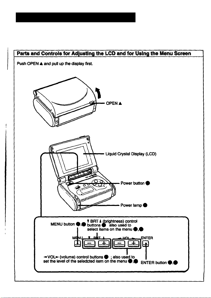
Location of Parts and Controls
For details, refer to the pages indicated in circles.
Page 8
Location of Parts and Controls
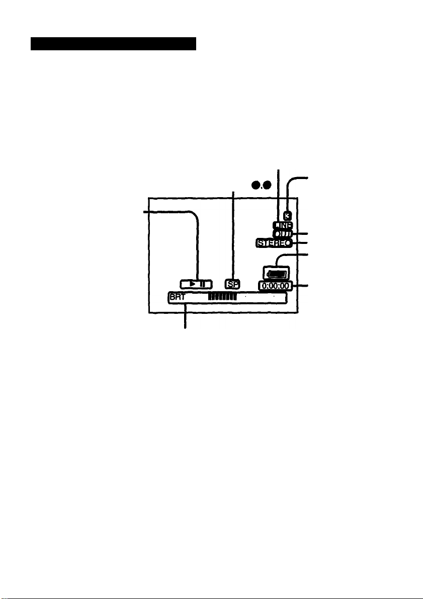
On-Screen Displays
Operating mode indication
# : Recording
• II : Recording pause
► ; Playback
► II ; Playback pause
►► : Fast fonward
: Rewinding
; Cueing
t2l
; Reviewing
: Slow
LINE/ACC PACK indication (
Tape speed indication
Volume or brightness level indication t
VOL
BRT
Channel indication
(only when the TGV-3
is installed)
Inputroutput indication (
Stereo indication
Remaining battery
capacity indication
Tape counter
indication 9
Note
Ail indications are illustrated as if they were actually displayed at the same time; however some of
them are not displayed at the same time.
8
Page 9
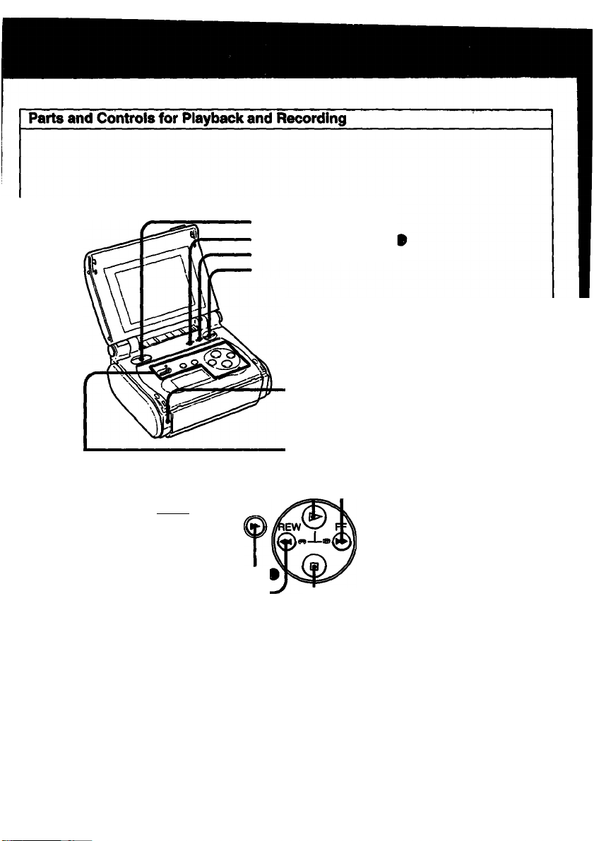
PAUSE U button I
REC->* Pi^ESLOW
REC (recording) • knob
and iamp #,## SLOW button
REW «(rewind) button
POWER button#
COUNTER RESET button (
OISPUY button #,#
EJECT A button###
POWER lamp I
O (play) button #
FF PP (fast winding) button
©
□ (stop) button (
Page 10
V.-:. . -
Location of Parts and Controls
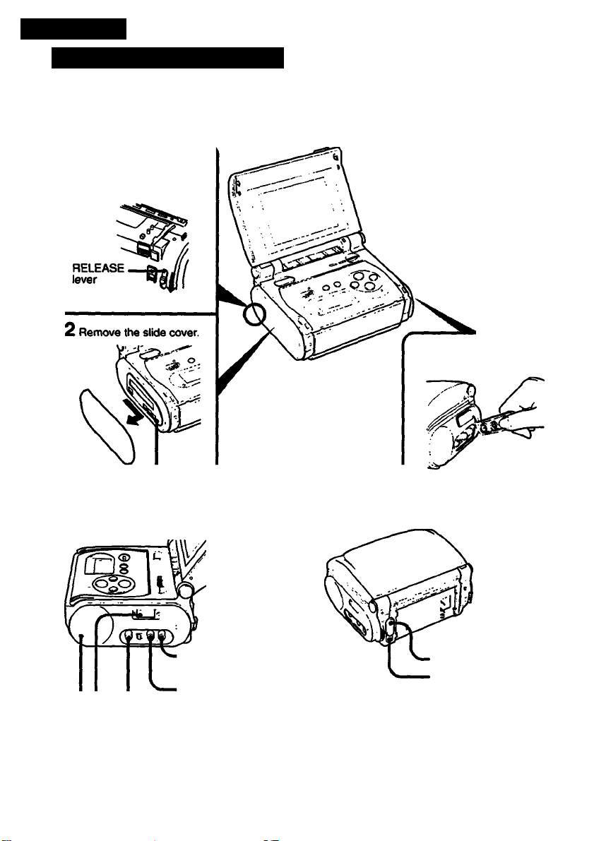
Parts for Connections
1 Slide the RELEASE lever
in the direction of the arrow.
Remove the terminal
protection cover.
Terminal for tuner timer unit.
10
AUDIO R INAJUTjack
^OTO^fWUT jack
■VIDEO inout/outputjack
• AA/ OUT terminal (for future use)
•Speaker
i^TOU^u^aj
n (phones) jack #
REMOTE terminal (
Page 11
Getting Started
Power Sources
You can select the best power source for your own needs.
Place Power source
Indoors
Outdoors
in a car
AC power adaptor
AC'SIO (supplied)
Battery pack
NP-55H (supplied), NP-60D, NP-66H, NP-77HD, NP-77H,
NP-80orNP-800
DC pack OCP-77 or Car battery charger/adaptor OC-S10
NP-55H
Page
12
To a wall outlet
13
NP-80
17
Only the AC-S10 and the NP-55H are supplied; the other accessories for your special needs are available
from your Sony dealer.
Disconnecting the power source during recording or piayback operations may damage the inserted
cassette tape. If this should happen, supply power again immediately and turn on the power.
Page 12
^wer èources
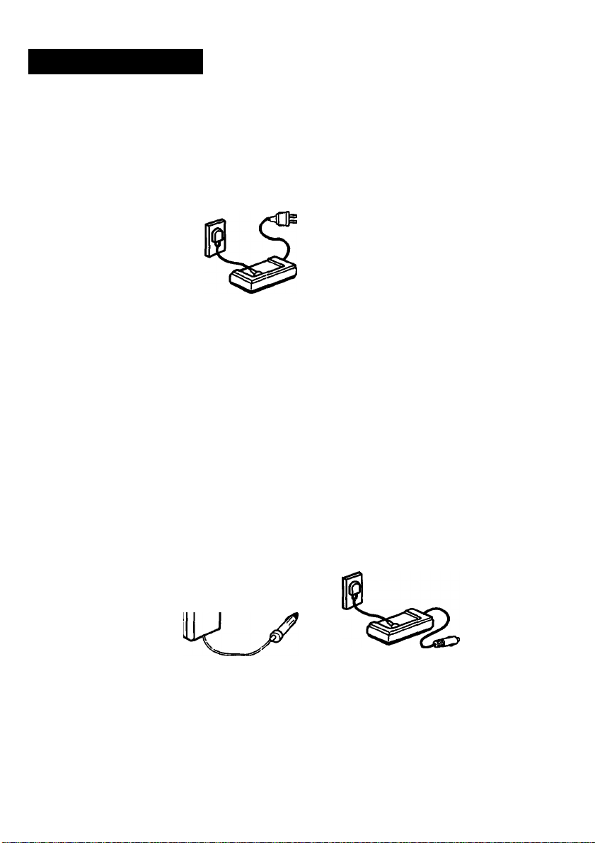
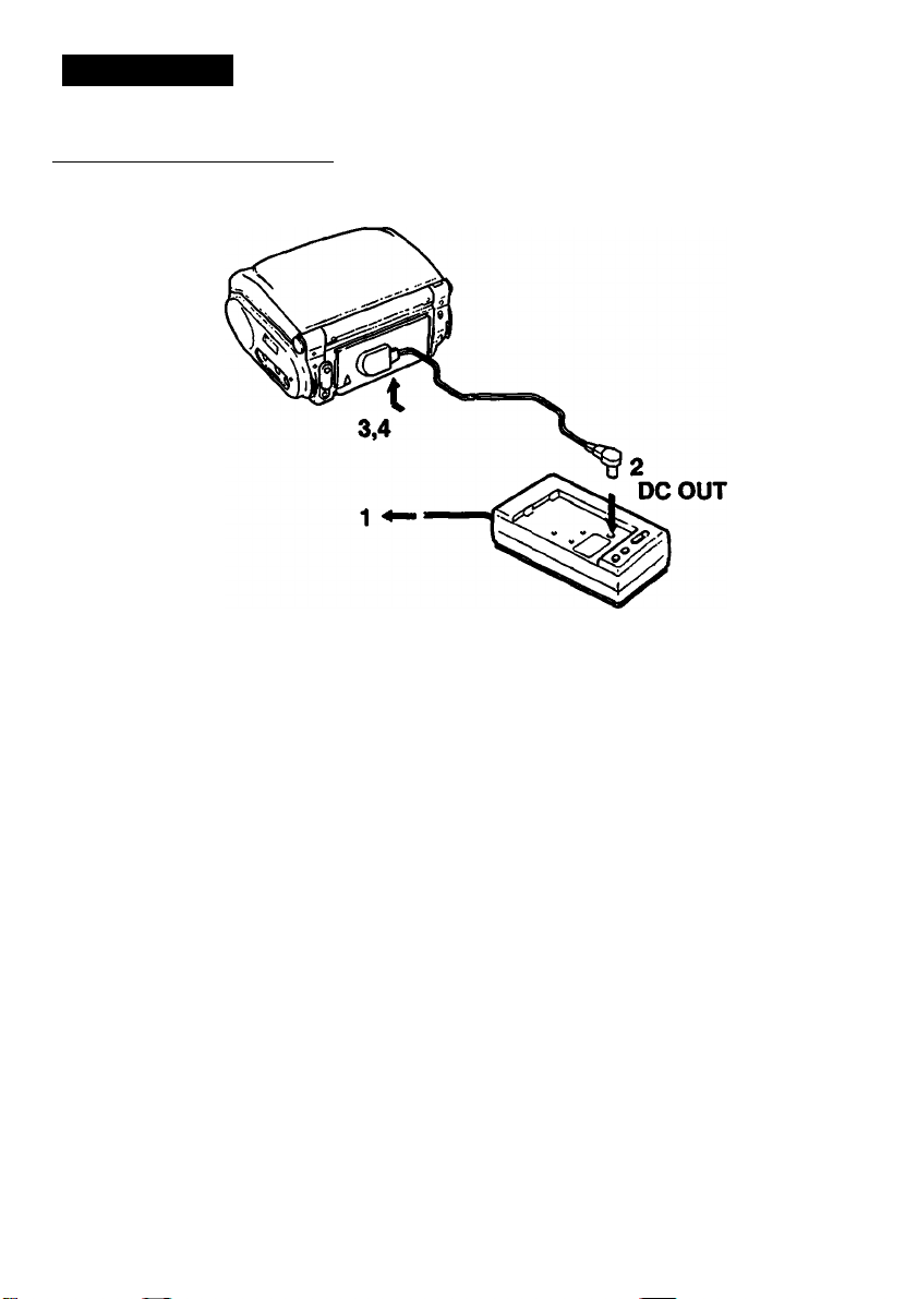
Using a Wall Outlet for Indoor Use
Use the supplied AC-S10 AC power adaptor.
1 Plug in the AC power adaptor to a wall outlet.
The POWER lamp (green) on the AC-S10 lights up and the power turns on.
2 Insert one end of the connecting cord (supplied with the AC-S10) into the DC OUT jack of the
AC-S10.
3 Align the upper side edge of the connecting plate with the white line printed on the video
recorder/monitor so that the slots of the connecting plate (the other end of the connecting
cord) are postitioned over the tabs of the battery mounting surface.
4 Press the connecting plate and slide it in the direction of the >■ mark.
To remove the connecting plate
Slide out the connecting plate while sliding the ВАТТ release knob.
CAUTION
TO PREVENT ELECTRIC SHOCK. DO NOT USE THIS POLARIZED AC PLUG WITH AN EXTENSION
CORD. RECEPTACLE OR OTHER OUTLET UNLESS THE BLADES CAN BE FULLY INSERTED TO
PREVENT BLADE EXPOSURE.
• The unit is not disconnected from the AC power source as long as it is connected to a wall outlet.
• One blade of the plug is wider than the other for the purpose of safety and will fit into a wall outlet only
one way. If you are unable to insert the plug fully into the outlet, contact your dealer.
• While the unit is in use. particularly during charging, keep it away from AM receivers and video
equipment because it will disturb AM reception and video operation.
12
Page 13
Using a Battery Pack for Outdoor Use
To charge a battery pack
Before using a battery pack, make sure to charge it first even if it is newly purchased. Beside the
supplied NP-S5H battery pack, optional NF-60D, NP-66H, NP-77HD, NP-77H, NP-80 and NP-80D
battery packs, as describ^ on page 11, are available.
Use the supplied AC.S10 AC power adaptor to charge a battery pack.
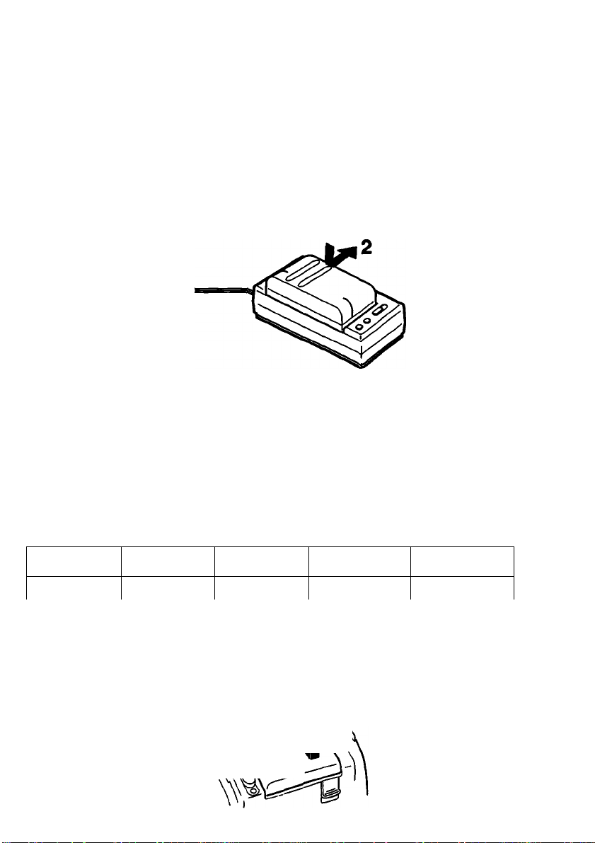
1 Plug in the AC power adaptor to a wall outlet.
The POWER lamp (green) on the AC-S10 lights up and the power turns on.
Install the battery pack in the AC-S10.
Align the flat side of the battery pack with the line on the AC-S10. Then push down and siide the
battery pack in the direction of the arrow. The REFRESH lamp (red) lights up first and then it goes
out. When the CHARGE lamp (orange) lights up, battery charging begins. When the battery is
charged, the CHARGE lamp goes out. Unplug the AC power adaptor and the POWER lamp goes
out. (Refer to the instructions provided for the AC-S10 as well.)
Required charging time:
NP-SSH
(supplied)
70 min. 80 min.
(Approx, minutes using AC^IO)
• The battery pack cannot be charged when using the AC power adaptor is used to operate the unit.
• An NP-55H, NP-60D, NP-66H, NP-77HD, NP-77H, NP-80 and NP-80D battery pack can also be
charged with the BC-S10 or BC-77 battery charger.
To attach a battery pack to this unit
Align the upper side edge of the battery with the white line printed on the video tecorder/monitor so
that the slots of the battery are positioned over the tabs of the battery mounting surface, and slide the
battery pack while pressing it. Jfe—n \ ^
NP-60D
NP-66H
100 min. 140 min.
NP-77H/77HD
NP-80f80D
155 min.
Page 14

To check the remaining battery capacity
When a battery pack is installed, press DISPLAY to show on the screen the remaining battery capac
as well as other indications (see page 8 for other indications).
To cancel this display, press DISPLAY again.
A fullyKtharged battery pack lasts for approximately:
NP-55H NP-60D NP-66H
Playback
(with TGV>3 connected)
Recording
(without TGV-3 connected)
Watching TV programs
Recording TV program 50 min. 55 min. 75 min. 100 min. 110 min.
SO min.
60 min. 65 min. 90 min. 120 min.
60 min.
55 min.
65 min. 90 min. 120 min. 130 min.
75 min. 100 min. 110 min.
NP-77H/77HD NP-80/80D
130 min.
If you use the NP-60D, NP-77HD, NP-80D battery pack which has the battery life indicator, the remaining
battery capacity indicated on the LCD may be different from that indicated by the NP-60D, NP-77HD,
NP-6(X) battery pack. The indicator on the NP-60D, NP-77HD, NP-80D battery pack is more accurate.
14
Page 15

Using the Battery Pack Efficiently
Preparing battery packs
Prepare 2 or 3 times more battery power than you plan to use.
The published battery capacity is measured in a continuously playing VCR
at room temperature starting with a fully charged battery. Fast winding or
rewinding uses much power than normal playing. Consequently, battery
consumption becomes faster when these operations are performed
frequently.
Battery consumption is faster in a cold climate
Cold climates reduce the efficiency of a battery and cause it to run out
more quickly.
When to replace battery packs
When a battery pack is fully discharged, the POWER lamp starts blinking
slowly. During recording, “BATTERY” also starts lighting on the screen.
Replace the battery when the POWER lamp starts blinking rapidly.
Turn off the video recorder/monitor power before replacing the battery.
Especially during recording, keep the cassette inside the cassette holder
while replacing the battery. When a fresh battery is attached, recording can
be resumed smoothly without any picture distortion.
Notes on charging
Before using a battery pack, charge it fully. A newly purchased battery pack
also needs to be charged before its first use.
Recharge a battery pack only when it is fully used out
Avoid recharging only partly used battery packs. Repeated charging of
partly discharged battery packs reduces their capacity and shortens their
overall life span. The original capacity can sometimes be recovered by fully
discharging and then fully recharging the battery pack.
Page 16

Power Source
Rechargeable battery packs
Battery pack care
• Remove the battery pack from the video recorder/monitor after use, and keep it in a cool place. When
the battery pack is installed on a video recorder/monitor, a small amount of current flows to the recorder
even if the POWER switch is turned off. This causes overdischarge and so shortens battery life.
• The battery pack is always discharging a little even when not in use. Thus, the battery should be
charged before each use.
• If the terminals (metal parts on the back) are dirty, the battery capacity will be reduced. When the
terminals are dirty, or when the battery pack has not been used for a long time, attach and remove it
several times. This will improve the contact between the battery pack and the video recorder/monitor.
Also, wipe the + and - terminals with a soft cloth or paper.
• If the battery pack is not used for a long time (about 1 year) and you charge it again, the battery capacity
will be reduced. After several charging and discharging cycles, the battery will recover its original
capacity.
How to use the switch on the battery pack "\ Switch
Use this switch as a reminder of charging.
Set the switch to the no-marked position when the charging is completed.
Set the switch to the red-marked position when the battery is discharged.
Battery life
A battery can be fully charged and discharged about 500 times under nonnal temperatures. If “BATTERY”
appears just after turning on the recorder, even though a fully charged battery pack has been installed,
replace the battery pack with a new one.
Best temperature for charging
A lower temperature requires a longer charging time.
Charging under a temperature ranging from lO'^C to 30°C (S0°F to 86’F) is recommended.
Why a battery pack heats up
While a battery pack is being charged or used, the chemical change occurring inside the battery pack
release heat. The battery pack becomes warm, but this is normal and not dangerous.
Warning
If the + and - terminals are short-circuited with a piece of metal, the battery heats up abnormally. This
is very dangerous. Never put an uncovered battery pack in a pocket together with a key holder or
other metals.
16
Page 17

Using a Car Battery
DCP-77 (not supplied)
1 Attach the DC pack to the video recorder/monitor by aligning the upper side edge of the DC
pack with the white line on the video recorder/monitor and slide the DC pack in the direction
of the ^ mark while pressing it.
2 Plug the power cord into the cigarette lighter socket.
• Only connect the DCP-77 to a car with a negative ground 12 V or 24 V battery.
• The DCP-5S is not recommended for this unit because its power is not enough to operate this unit.
Notes
• Be careful not to let any metal object touch the metal projection on the battery pack. When the battery
pack is not in use, keep it in its case.
• Keep the video recorder/monitor away from any power source. Such sources may cause noise to appear
on the screen.
Cautions on using this unit in a car
• For your safety, do not watch video tapes or operate the controls while driving.
• Avoid leaving the unit in a place with very high temperatures. If you do, it may cause distortion of the
cabinet or malfunction of the unit.
• If you use this unit while the car engine is stopped, the car battery will be discharged. Avoid running
this unit from the car battery more than 12 hours without recharging it.
• Remove the car battery cord from the cigarette lighter socket if you do not use the unit for a long
time.
17
Page 18

I
Basic Operations!
Playing Back Tapes
Make sure that the power source is attached to this unit.
Inserting a Cassette
1 Push OPEN A and open the display.
2 Press EJECTS.
The cassette holder opens automatically.
Do not open the cassette holder forcibly.
aB EJECT
3 Insert a cassette with the window side facing up.
4 Press the PUSH mark.
The cassette holder closes automatically.
When you press EJECT A, power is supplied and the cassette holder opens even if the power is turned
off. After the cassette holder opens, the power goes off automatically. Press POWER if you want to
continue the operation.
18
Page 19

Ejecting a Cassette
1 Press EJECT a.
Make sure the tape is not running.
EJECT
2 Remove the cassette.
3 Press the PUSH mark.
The cassette holder closes automatically.
Cassette care
• Store cassettes in their cases when they are not in use and keep them in an upright position to keep out
dust and prevent uneven winding.
• Never insert a cassette upside down into the cassette holder.
• Never cover the small holes on the rear of a cassette or insert anything into the holes.
• Remove a cassette from the video recorder/monitor when it is not in use.
19
Page 20

Playing Back Tapes
If power supply Is interrupted
The levels of volume and brightness are automatically set to the center point on the level indication bars
on the screen.
20
Page 21

To turn off the power to this unit
Press POWER again so that the POWER lamp goes off.
To rewind the tape and piay it back automatically — Auto play
Press > (play) while pressing REW '^'4.
To mute the picture and sound
Close the LCD so that the LCD turns off and that sounds are not heard from the speaker.
To restore the picture and sound, push OPEN A and pull the LCD up.
For private listening in stereo
Connect the supplied stereo earphones to the 0 (phones) Jack. No sound will be heard from the speaker.
Listening to Stereo and Dynamic Bass (MEGABASS) Sound
You can listen to dynamic bass sound in stereo by using the supplied stereo earphones; however, you
cannot listen to this sound though the speaker.
Relation between outputs and sound effects
Stereo effect
Earphones Active
Speaker Inactive
Line output Active
MEGABASS effect
Active
Inactive
Inactive
To activate MEGABASS Sound
Select “MEGABASS” from “SOUND” on the menu screen. For details on the procedure, see pages 25 and
26.
To inactivate MEGABASS. select “NORMAL” from “SOUND” on the menu screen.
Page 22

Playing Back Tapes
Various Playback Modes
To stop the tape for a
moment — Still picture
To view the slow
playback picture
To locate a particular
point while viewing the
picture
— Picture search
To view the picture at
high speed
— FR picture search
During
playback
During
playback
During
playback
During
playback
During
rewinding
During
fonwarding
rAU9C
©
SLOW
©
BEW
©
FF
©
BEW
©
FF
©
► II
To resume normal
playback, press > or
PAUSE II. This mode will
be automatically released
and the unit will stop after
five minutes.
To resume normal
playback, press >.
(or normal playback
resumes automatically after
one minute.)
When you release the
button, the unit will return to
the previous mode.
If streaks appear In slow playback pictures on LCD
Adjust the pictures during slow playback, by using the menu saeen. so that streaks disappear from the
pictures. For details on the procedure to adjust “SLOW TRACKING* on the menu screen, see pages 25
and 26.
When the playback picture Is viewed on another TV or monitor
The pictures may possibly become black and white or shakes vertically in picture search and FR picture
search modes. Moreover, noise appears in the still and slow pictures
22
Page 23

Adjusting the Picture
You can adjust tints and the depth of colors on the menu screen.
1 Press MENU.
The menu screen appears.
MENU
Q
SOUt40 NORMAL
P RECMOOE $P
HUE
COLOR
Slow TRACKING
♦ 8R LP
S6L(V «1 S(TU»| (6NT)
2 Press ▼ or ▲ to select the item to adjust.
3 Press ^ or to make adjustments.
Each time you press 4 or P, the selected item is
To adjust tints
MENU
SOUND N0RL1AL
- VOL ►
(ZDS
RECMODE SR
R HUE
COLOR
SLOWTRACKINO
RED GREEN
SELip *1 m(PP| lENTj
red.
4 Press ENTER.
T BRT 4
SB
as shown below.
green less depth i
ENTER
□
MENU
SOUND
RECMOOE
HUE
P COLOR
aOW TRACKING
LIGHT
SELip *1 SETlppl ENn
1
NORMAL
SP
To adjust the depth of colors
MENU
SOUND NORMAL
RECMODE SR
HUE
P COLOR
SLOWTRACKINO
LIGHT ^ DEER
SEL(P At ^l«P| lENTJ
. more depth
Page 24

Playing Back Tapes
Using the Tape Counter
The counter indicates the tape transport in hours, minutes and seconds.
During playback or recording, it shows you the playback or recording time.
1 Press DISPLAY.
The tape counter appears on the screen.
2 Press COUNTER RESET during playback or recording at the point you want to locate later.
The counter is reset to 0:00:00.
COUNTER RESET
Hours Minutes Seconds
Notes
• When you play back a blank tape, the tape counter does not function.
• The counter reading and the point on the tape may not correspond exactly. Use the counter as a guide.
• The difference between the counter reading and the point on the tape may increase by several seconds
in the following cases:
- after repeated fast-forward and rewinding
-when playing back a tape recorded both in SP and LP modes
-when playing back a tape having a blank portion between recorded portions
24
Page 25

Settings on the Menu Screen
You can set five items on the menu screen. You can use this unit with the settings preset at the factory
(indicated by • in the list on page 26).
If you want to change the settings, follow the procedure described below.
Opeixrtlon
1 Press MENU.
The menu screen appears.
MENU
Q
MENU
P SOUND
RECMOOE
HUE
COLON
SkOWTNACKlNO
seti» 4l
2 Press ▼ or A to select the item to adjust.
T BRT A
SS
3 Press '4 or to select the setting you want
Each time you press < or P, the selected setting
changes and is indicated by • . . yQJ- *T .
HUE
COLOR
SLOWTRACKMG
•8A LP
SEl(« «I S6TUAI
MENU
P RECMOOE
SSI
4 Press ENTER.
ENTER
Q
Note
You cannot cancel the setting procedure once you start changing the setting.
NORMAL
Sf>
• NORMAL MEGASASS
SETIapI (ENTI
SOUND
HUE
COLON
SLOW TRACKING
8P • LP
SEUv Al SET |4P)
NORMAL
LP
—A-
ISNTI
red
Page 26

Settings on the Menu Screen
Menu Screen List
items Settings
SOUND
REC MODE e sp
HUE
COLOR
SLOW
TRACKING
#: factory setting
* Levels are set at the middle of the bar at the factory.
e NORMAL To inactivate the
MEGABASS To emphasize bass sound
LP
Level indication bar' To adjust tints
Level indication bar
Level indication bar' To adjust the tracking for
Setting purpose
MEGABASS effect
To record at normal speed
To record at double normal
soeed
To adjust the depth of color
slow motion playback picture
When to use
When emphasizing bass sound
When recording
When the colors of picture are strange
When watching slow motion pictures
26
Page 27

I
Operations with other equipment
Recording a TV program
You cannot watch or record a TV program on this unit since this unit does not have a built-in tuner.
However, if you instail the suppiied TGV-3 tuner timer unit to this unit, you can watch and record a TV
program.
Here's only explanation of how to record a TV program after connecting the tuner to this unit. For
installation, channel preset, channel selection, etc., refer to the instruction manuals supplied with the
TGV-3.
Operation
1 Install the TGV-3 tuner timer unit to this unit, and carry out the necessary setting, such as
channel preset, on the TGV-3. (For more details, refer to the instruction manual supplied with
the TGV-3.)
2 Set the TUNER/LINE selector on the rear of the TGV-3 to TUNER.
3 Turn on the power of this unit
‘ACC PACK” appears on the screen for several seconds.
4 Press CH-/+ on the TGV-3 to select the TV program to be recorded.
5 Insert a cassette as explained on page 18.
EJECT
(ACC PACK POWER OFF)
LINE
CH
i-i ((+]
27
Page 28

Recx)rding a TV Program
6 Select the tape speed (“SP” or “LP” from *‘REC MODE”) on the menu screen of this unit.
See ‘Settings on the Menu Saeen” on pages 25 and 26.
7 Slide REC on this unit in the direction of the arrow.
Recording starts.
To pause recording
Press PAUSE II.
To resume recording
Press PAUSE II again.
If you do not press PAUSE II again within five minutes, the pause
mode wili be released automatically and the unit will stop.
When changing the channel while recording
Set this unit in recording pause mode and then select another channel. You cannot watch another
program while recording.
When recording from the beginning of the tape
Advance the tape for about 15 seconds before recording. This will prevent missing the starting point when
piaying back on another VCR.
When the tape is recorded to the end
The tape stops automatically, but'the unit is not turned off. If you are not going to continue operation, turn
off the power by pressing POWER.
About recorded sound
Recording level Is always fixed automatically.
The VOL - and have no effect on the recorded sound level.
REoio»
(c=ii)
To stop recording
Presso (stop).
If power supply is interrupted while recording
Recording stops.
28
J
Page 29

Recording/playback time
Two tape speeds (SP/LP) can be selected on the menu screen (see pages 25 and 26).
The recording time in LP mode is twice as long as that in SP mode. For better picture and sound,
recording in SP mode is recommended. During playback, the mode in which the tape has been recorded
is selected automatically.
Difference in coior systems
There are different formats of the TV color broadcast and electricity system: NTSC, PAL and SECAM.
Video cassette tapes are made to correspond to one of these formats. Use NTSC format cassette tapes
for this unit. You will find ''P6'' on the package of NTSC cassettes.
To prevent accidentai erasure
Slide out the tab on the back of the cassette so that red color is visible.
To re-record on the cassette, slide the tab back.
Rear side of a cassette
________
Recording cannot Recording can
be made.
Note
If you record, using this unit, on a tape that has been recorded with PCM sound, and then if you play back
this tape on a VCR with PCM function, the sound may be cut off occasionally. If this happens, set the
audio monitor switch of the VCR to the standard position.
_________
1
_______
□
be made.
29
Page 30

Editing Tapes
You can not record a TV program since this unit does not have a built-in tuner. However, you can edit a
tape with the another VCR (8 mm, Beta, or VHS format) connected through the VIOEO/AUOlO input/
output jacks of this unit.
Editing from Another VCR
Connection
VCR
s
To VIDEO
(yellow)
If the other VCR is monaural type, use the VMC-910MS or VMC-920MS (not supplied).
Operation
,To AUDIO UR
(white/red)
AudkWideo cord VMC-910S/920S*
(not supplied)
To VIDEO
OUT
(yellow)
To AUDIO
OUT
(white(L)red(R))
1 Turn on the power of both units.
2 Insert a source tape into the other unit (playback) and a tape for recording into this unit
(recording).
If the supplied TVG-3 tuner timer unit is installed, set the TUNER/LINE selector to LINE.
3 Select the tape speed (“SP” or “LP” from “REC MODE”) on menu screen of this unit.
See ‘Settings on the Menu Screen” on pages 25 and 26.
4 Activate the EDIT function* if it is provided with the other unit.
5 Locate the playback start point and press the pause button on the other unit.
6 Slide REC in the direction of the arrow and press PAUSE H on this unit.
This unit is now put in recording pause mode.
REO*o^
PAUSE
(™) ^ 0
30
à
Page 31

7 Press the pause buttons (PAUSE II on this unit) on both units to release the pauses.
8 Press the pause buttons on both units to pause the units again.
9 Repeat steps 7 and 8 to edit more scenes.
10 After editing Is completed, press the stop buttons (□ on this unit) on both units to
playback and recording.
* Although this unit does not have an EDIT function, using this function on a VCR connected to this unit
for editing will avoid deterioration of the picture on the duplicated tape.
Notes on connection
Note that cord plugs and jacks are color coded. Red plugs and jacks are for the right audio channel, white
ones are for the left audio channel and yellow ones are for video signals.
Page 32

Editing Tapes
Editing from the VCR Equipped with the CONTROL L (LANC tt ) Terminal
Connect the REMOTE terminal on this unit and the CONTROL L terminal on the other unit, and then set
the other unit's LANC mode to “M.”
PlaybacK/pause on the other unit and recording/pause on this unit can be operated simultaneously from
the other unit by pressing only one button.
Connection
To REMOTE (LANC)
VK-820 (not supplied)
To VIDEO
(yellow)
* If the other VCR is monaural type, use the VMC-910MS or VMC-920MS (not supplied).
Operation
To AUDIO L/R
(white/red)
Audio/Video cord VMC-910S/920S*
To CONTROLLA
r
(not supplied)
VCR
To VIDEO
OUT
(yellow)
iE
To AUDIO
OUT
(whne(L)red(R))
1 Turn on the power of both units.
2 Insert a source tape into the other VCR (playback) and a tape for recording into this unit
(recording).
3 Select the tape speed (“SP” or "LP” from “REC MODE") on the menu screen of this unit.
See “Settings on the Menu Screen” on pages 25 and 26.
4 Activate the EDIT function if it is provided with the other VCR.
5 Locate the playback start point and press the pause button on the other VCR.
6 Slide REC in the direction of the arrow and press PAUSE II on this unit.
This unit is now in recording pause mode.
REO*o^ PAUSE
(^1 ^ 0
V
32
Page 33

7 Press SYNCHRO EDIT on the other equipment to release the pause.
8 Press SYNCHRO EDIT on the other equipment to pause both units again.
9 Repeat steps 7 and 8 to edit other scenes.
10 After editing is completed, press the stop buttons (□ on this unit) on both units to stop
playback and recording.
About tt(LANC)
LANC stands for Local Application Control Bus System. The LANC terminal is used for controliing the tape
transport of video equipment and peripherals connected to it. This terminal has the same function as
those indicated as CONTROL L or REMOTE.
Editing with an Editing Controller
By adding an editing controlier to the video equipment connected through the LANC terminais, the
various piece of equipment can be operated with the controller.
AudioArideo cord VMC-910S/920S
Edinting controller
To VIDEO
OUT
To AUDIO
OUT
To e REMOTE
Connecting Cord
o
^ .j j .je
a o o OBB
To CONTROL L
(LANC)
•)PO
è^To
T
To VIDEO,
CONTROLL
(LANC)
Connecting Cord To REMOTE
(yellow)
Page 34

Editing Tapes
Editing from This Unit to Another VCR
Connection
GV-S50
C fcJK« »f«W
-
--------------—inrr-T^r~nB irfrliniJKL'
To VIDEO
(yellow)
* If the other VCR is monaural type, use the VMC-910MS or VMC-920MS (not supplied).
Operation
To AUDIO UR
(white/red)
AudioA/ideo cord VMC-910S/920S*
(not supplied)
To VIDEO IN
(yellow)
To AUDIO IN
(white (L)/red (R))
1 Turn on the power of both units.
2 Insert a source tape into this unit (playback) and a tape for recording Into the other VCR
(recording).
3 Select the tape speed (SP/LP) on the other VCR.
4 Activate the EDIT function if it is provided with the other VCR.
5 Locate the playback start point and press PAUSE II on this unit.
6 Put the other VCR into recording pause mode
7 Press the pause buttons (PAUSE H on this unit) on both units to release the pause.
8 Press the pause buttons on both units to pause the units again.
9 Repeat steps 7 and 8 to edit more scenes.
10 After editing is completed, press the stop buttons O on this unit) on both units to stop
playback and recording.
34
Page 35

VIDEO/AUDIO Input/Output Jacks
The VIDEO/AUDIO input/output jacks automatically become either input or output jacks according to the
operating modes of this unit.
Relation between the operating mode and the input/output status
© When the LINE/TUNER selector on the TGV-3 is set to LINE or the TGV-3 is not installed.
Operating Mode Input/Output Status
Stop
Playback Output
Recording
© When the LINE/TUNER selector on the TGV-3 is set to TUNER (power is supplied).
Input
Input
Operating Mode
Stop
Playback Output
Recording Output
The current status will appear on the screen for five seconds in the following cases:
• when the status has changed
• when vou Dress DISPLAY
Input/Output Status
Output
Page 36

Connecting Other Video Equipment
You can connect other video equipment such as a TV, monitor, video camera recorder, VCR, etc. through
the VIDEO/AUDIO input/output jacks.
For additional information, refer to the operating manuals of the equipment you want to connect.
Connecting a TV or Monitor
This ailows you to view playback pictures on larger screen.
® TV or monitor with audioArideo inputs
TV or monitor
To VIDEO n fl fl To AUDiO L/R
(yellow) |f|ffl(white/red) ^eliowf°
Audio/Video cord VMC-910S/920S*
(not supplied)
* If your TV or monitor is monaural type, use the VMC-910MS or VMC>920MS (not supplied).
_______________________
(D TV without audio/video inputs
Use the RFU-89UCKA RFU kit (not suppiied).
if the VHF input terminal of your TV
is a 300-ohm twin-lead plug, use №e
antenna selector adaptor supplied
with the RFU kit.
RFU unit selector
Set to 3CH or 4CH
Note
The RFU 89UCKA includes the following accessories:
• RFU adaptor (1)
• Antenna selector (1)
• Antenna selector adaptor
GV-S50
To AUDIO
(white (L)/red (R))
RF OUT connector
—OO-^ To your TV
To set the channel for this unit
To view the playback picture of this unit, set the selector of the RFU adaptor to channel 3 or 4, whichever
channel is not active in your area, and select the same channel on the connected TV.
36
Page 37

Connecting a Video Camera Recorder
This allows you to monitor the pictures actually being taken.
Video camera recorder
To VIDEO
(yellow)
* If your camera recorder is monaural type, use the VMC-910MS or VMC-920MS (not supplied).
To audio
(white (L)/red (R)) Joy'D^O
'Audio/Video cord VMC-910S/920S*
(not supplied)
____________
(yellow)
Connecting a VCR
This allows you to dub or edit tapes as explained before. See pages 30 - 35.
To AUDIO L/R
(white/red)
Page 38

other Information
Maintenance
Main Unit
' When the unit is not used for a long period of time, periodically turn on the power and play back a tape
for about three minutes.
Clean the cabinet with a dry, soft cloth, or a soft cloth lightly moistened with a mild detergent solution. Do
not use any type of solvent which may damage the finish.
Video Head Cieaning
To ensure a dear picture, dean the video heads periodically.
If playback pidures are noisy or hardly visible, the video heads may be contaminated. If this happens,
clean the video heads with the Sony V8-25CLH cleaning cassette (not supplied) referring to the
instrudions supplied with it.
Caution
Do not use commercially available wet-type cleaning cassettes.
They may damage the video heads.
Note
If the V8-25CLH cleaning cassette is not available in your area, consult your Sony service facility.
Video Head Replacement
When playback pictures are not dear even after using the cleaning cassette, the video head may be
damaged. If this happens, the video head needs to be replaced with a new one. Consult your Sony
service fadlity for repladng the video head.
Built-in Lighting System
A built-in lighting system is installed inside the liquid crystal screen of this unit. Eventually the small
fluorescent tube used for this built-in lighting system wears out. If the tube becomes dim or goes off
immediately after you turn on the unit, even with new batteries, replace the tube with a new one. To
replace the tube, consult the dealer where you purchased the unit, or a Sony service facility. The expeded
life of the small fluorescent tube is about three years if this unit is used for an hour each day. When you
use this unit in a cold environment, the fluorescent tube will be dimmer at first. As soon as the temperature
of the tube rises, it will regain its original brightness.
LCD
’ Do not push the display forcibly.
’ If the unit is used in a cold place, a residual image may appear on the screen. This is not a maHundion
of the unit.
• Constant bright points of light (red, blue, or green) may appear on the screen. This is not a malfunction
of the unit.
38
Page 39

Moisture Condensation
If this unit is brought directly from a cold place to a warm place, moisture may condense inside the unit or
on the surface of the tape. If this happens, the tape may stick to the head drum, damaging both the tape
and the unit. Although this unit is furnished with a moisture sensor to prevent possible damage from
condensation, it cannot prevent damage if a tape is left inside the unit. It is best to remove the tape if you
are not using the unit.
If moisture condenses inside the unit
“DEW” appears on the screen.
No button will function except EJECT
Eject the cassette, turn off the unit and leave the cassette holder open for at least an hour.
The unit can be used again if “DEW” does not appear when one of the tape transport buttons 0>, □,
PAUSE II, FF ►► or REW «) is pressed.
Using Your Video Recorder/Monitor Abroad
If you prepare fully charged battery packs and the supplied AC power adaptor (which can be used in all
areas with a local power supply ranging from 100 V - 240 V), you can use your video recorder/monitor in
any country. However, since the shape of the outlet differs widely in the world, you may need an AC plug
adaptor.
Each country has special TV color broadcast and electricity systems. This unit Is designed to play back
and record using the NTSC color video signals. Playback and recording of video sources of other color
signals (PAL and SECAM) cannot be guaranteed.
Countries using NTSC color signal
Bahama Islands, Canada, Central America, Japan, Korea, Mexico, Taiwan, the Philippines, U.S.A., etc.
Page 40

Specifications
System
Video recording system
Audio recording system Rotary head, FM stereo system
Video signal
Usable cassettes
Tape speed
Recording time SP mode; 2 hours
Playback time SP mode; 2 hours
Fast forward/rewinding time
LCD section
Picture
On-screen display
Inputs/outputs
VIDEO/AUDIOIN/OUT
Video input
Video output
Audio input
Audio output
Speaker
Phones
« REMOTE (UNO)
Rotary two-head helical scanning FM system
EIA standard, NTSC color
8 mm video format cassettes
SP: approx. 1.43 cm/sec.
LP: approx. 0.72 cm/sec.
LP mode; 4 hours
(with Sony P6-120 cassette)
LP mode; 4 hours
(with Sony P6-120 cassette)
Approx. 8 minutes
(with Sony P6-120 cassette)
4 inches measured diagonally
8.2 X 6.2 cm (3'/4 x 2'h inches)
TN LCD/TFT active matrix method
Total dot number; 89.856 (384 x 234)
Selectable automatically according to the operation
Phono jack, 1 Vp-p, 75 ohms, unbalanced, sync negative
Phono jack, 1 Vp-p, 75 ohms, unbalanced, sync negative
Phono jack, -7.5 dBs (0 dBs=0.775 Vrms). input impedance
more than 47 kilohms
Phono jack. -7.5 dBs (330 mV) at load impedance 47 kilohms.
output impedance less than 10 kilohms
7.2 ohms, 200 mW
Minijack, 8 ohms
Stereo mini-minijack
General
Power requirements
Power consumption
Operating temperature
Storage temperature
Dimensions
Weight
Accessories supplied
40
Battery mounting surface input; 6.0 V (battery pack).
7.5 V (AC power adaptor), 6.5 V (DC pack DCP-77)
6.7 W (for continuous playback)
OX to 40X (32°F to 104°F)
-20X to OO'C (-^''F to 140®F)
148.5 X 83 X127 mm (w/h/d)
(5V* X 3*/» X 5 inches)
Approx. 980 g (2 lb 3 oz) not including battery pack
Tuner timer unit TGV-3 (1)
Battery pack NP-55H (1)
AC power adaptor AC-S10 (1)
Stereo earphones (1)
Signal splitter (1)
Lithium battery CR2032 (1)
Page 41

AC-S10
Power consumption
Power requirements
Output voltage
Battery charge terminal:
Operating temperature
Storage temperature
Dimensions
20 W
100-240 VAC. 50/60 Hz
DC OUT: 7.5 V, 1.6 A in operating mode
10 V, 1.3 A in charge mode
0°C to 40*C (32®F to 104°F)
-20®C to +60®C (-4<>F to 140'F)
Approx. 72 X 39 X141 mm (w/h/d)
(27a X 17i6 X 5Va inches) including projecting parts and controls
Weight
Design and specifications are subject to change without notice.
Approx. 330 g (12 oz.)
List of Recommended Accessories
Model Name
Battery pack NP-80D, NP-80, NP-77HD, NP-77H, NP-66H
Battery charger
Car battery charger DC-S10
DC pack DCP-77
Connecting cord
Cleaning cassette V8-25CLH
orNP-60D
BC-S10orBC-77
VMC-910S/920S (1 m/2 m) 30,32,34,35,36,37
Page
13
13
17
17
38
Page 42

Troubleshooting
If you have a problem with this unit, first check the power supply source, then go through the list below
before calling the Sony service facility. Should the problem persist, consult your Sony service facility.
Symptom
The unit does not work
even though the
POWER switch is
turned on.
Power turns off
automatically during
1
operation.
The battery pack is
quickly discharged.
The playback picture is
not clear.
a>
e
f
8
Recording cannot be
s
made.
C
«
0
1
The cassette cannot be
£
ejected.
The picture does not
appear.
The picture appears but
no sound is heard.
o
3
Snow and noise • Adjust “SLOW TRACKING” on the menu screen (pages 25 and
No color
• The battery pack is not attached.
• The battery pack is exhausted.
• AC power adaptor or car battery cord is disconnected.
• The battery pack is exhausted.
• The temperature is too low.
• The battery pack is worn out.
• The battery pack has not been charged fully.
• The video heads may be contaminated. Clean the heads using the
• The video heads may be damaged.
• The safety tab on the cassette is slid out to expose the red mark.
• Moisture condensation has occurred.
• The tape is at its end.
• A cassette is not inserted.
• Moisture condensation has occurred.
• No power is supplied to the unit.
• The battery pack is exhausted.
• Incorporated flourescent tube is worn out.
• Adjust the volume.
• Disconnected the earphones.
* Adjust “COLOR” on the menu screen (pages 25 and 26).
Possible causes and/or corrections
Charge it. (page 10)
Sony V8-25CLH cleaning cassette (not supplied).
Have the video heads replaced with new ones.
Use a fully charged battery, (page 10)
26).
42
Page 43

Warning Displayed on the Screen
The following indications appear on the screen indicating the operating environments and cautions.
These indications are not recorded on the tape, but are generated by the unit and only exist on the
screen.
Indication
Meaning
Although you are trying to
record.
• No cassette is inserted.
• The tape is at its end.
• The red mark on the
cassette is exposed
The battery is used up
(seepage 15).
Moisture condensation
occurs (see page 39).
 Loading...