

Page 1
SONV
Video Recorder/Monitor m
GV-M20
Operating Instructions
WIIIMII
i 1992 by Sony Corporation
mm m
Page 2

WARNING
To prevent fire or shock hazard,
do not expose the unit to rain
or moisture.
Tinis symool is intended to alert
the user to the presence of
uninsulated dangerous voltage'
e product's enclosure that
may be of sufficient magnitude to
constitute a risk of electric shock
This symbol is intended to alert
the user to the presence of
important operating and
maintenance (servicing)
instructions in the literature
accompanying the appliance.
Owner’s Record
The model and señal numbers are located on the bottom. Record the senai number m the space
' provided below. Refer to these numbers whenever you call upon your Sony dealer regarding this
j product.
I Model No. GV-M20 Serial No
INFORMATION
This equipment has been tested and found to
comply with the limits for a Class B digital device,
pursuant to Part 15 of the FCC Rules These limits
are designed to provide reasonable protection
against harmful inierference in a residential
installation. This equipment generates, uses and
can radiate frequency energy and. if not installed
and used m accordance with the instructions, may
cause harmful interference to radio
communications. However, there is no guarantee
that interference will not occur m a particular
installation, if this equipment does cause harmful
interference to radio or television reception, which
can be determined by turning the equipment off and
on. the user is encouraged to try to correct the
interference by one or more of the following
measures:
• Reorient or relocate the receiving antenna.
• Increase ihe separation between the equipment
• Connect the equipment into an outlet on a circuit
different from that to which the receiver is
connected.
• Consult the dealer or an experienced radio/TV
technician for help.
'/ou are cautioned that any changes or
moCthcaiions not expressly approved m this rnanual
could void your authority to operate this equipment.
Television programs, films, video tapes and other
materials may be copynghted Unauthorized
recording of such matenaJ may be contrary to the
provisions of the copyrght laws.
For the customer In Caiwda
This apparatus compilies with Class B limits lor
radio noise emmissions set out m Radio
Interference Regulations.
Precautions
• Operate the unit on 6.0 V (battery pack)/? 5 V (AC power adapior)/6 5 V (DC pack DCP-77),
• Oo not operate the unit where the temperature is below O^C (32°F) or above 40-C (tCW^F).
• For DC or AC power supply, use the accessones supplied or recommended m ihis manual.
• Should any solid cb)ect or liquid fall into the cabinet, unplug the unit and have it checked by qualified
personnel before operating it any further
• Avoid rough handling or mechanical shock to the unit.
• Do not apply excessive force to the LCD (Liquid Crystal Display).
• Remove and store video cassettes after recording or playback
• Do not wrap up the unit and operate it because heal may build up internally.
• Avoid using and storing the unit m the following locations.
-susceptible to vibration
- exposed to strong magnetic fields
- near TV or radio transmitters where strong radio waves are generated
-on the sand
Page 3
Table of Contents
[ Ovefwew of the GV-M20 .....................................................................................................5
Menu Screen .....................................................................................................................S
Localion of Parts arKl Conirois .........................................................................................6
PartsanoControIsfor Adjusting itie LCD and tor Using (tie Menu Screen .6
On-Screen Display
Parts and Controls for Playback and Recording
Parts for Connections.....................................................................................................9
Power Sources ......................................................................................................................10
Using a Wall Outlet lor Indoor Use.......................................................................11
Using a Battery Pack for Outdoor Use.................................................................12
Using tne Battery Pack Efficiently...........................................................................14
Using a Car Battery.......................................................................................................16
Playing Back Tapes
Inserting a Cassette
Electing a Cassette .............
Watching Video Tapes
Various Playback Modes...
Adjusting the Picture
Using the Tape Counter....
Recording or Editing Tapes ............................................................................................23
UV'
Editing from Another VCR
-
- Ч Editing from the VCR Equipped with the CONTROL L
(LANC C ) Terminal..................................................................................
.............Hill iWhi
Editing with an Editing Controller
Editing from This Unit to Another VCR...........................................
VIDEO/AUDIO Inpul/Outpot Jacks
i* . 1
Connecting Other Video Equipment ........................................................
Connecting a TV or Monitor
Conneamg a Video Camera Recorder
Connecting a VCR ......................................................................................
Maintenance
Mam Unit
Video Head Cleaning
Built-in Lighting System
LCD............................................................................
Moisture Condensation
Using Your Video Recorder/Monitor Abroad ...
Specifications............................................
List of Recommended Accessones
Troubleshooting.........................................................
Warning Displayed on the Screen .....................
......
7
.......
.........
......
........
......................................................................
.......................................................
......................................................
..................................................................
..............................................
.....................................
.......................................
.................................
..................................
..............
.................................................
.................
...........
...............
................
. . 30
Overview of the GV-M20
The Video Walkman GV-M20 is an 8 rnm video recorder/monitor vnth a 3-incn LCD (Liquid Crystal
Display). Its compact and lightweight design allows you to play back video tapes anywhere and anytime
you like; however, it can not be used to watch and record a TV program since no tuner is incorporated
By conhectmg another VCR to this unit through VIDEO and AUDIO jacks, you can edit video tapes
A variety of optional accessones enable you to make the best use of this unit; for example, by connecting
It to a video camera recorder (not supplied), you can use this unit as a mon«or, and play back the
recorded pictures immediately.
8
• Easy-to-use menu screen
• Remainirtg battery capacity indication
Shows you the remaining capacity of the battery.
• REMOTE terminat
..17
23
25
27
. .28
29
30
31
.31
Allows remote control of this unit by other Sony video equipment.
The GV-M20 uses 8 mm video format cassettes. It records in SP mode (approximately i 43 cnVsecond)
and LP mode (approximately 0.72 cm/second) and can play back in SP and LP modes. The quality of the
playback picture in LP mode, however, will not be as good as that In SP mode.
lit abroad, see page 34.
You can choose the tape speed and adjust hues and colors by selecting them from the rr
The mam menu appears on the screen when you press MENU Select the desired item o
screen. For more details, see reference pages in the table below.
Menu screen !
Menu Item
REC MODE
HUE To adjust tints
COLOR
Setting purpoee Reference page
To select the tape speed (SP or LP) 21,23, 2$
To adjust the depth of colors
.i]____________________________________i
2'’ I
Page 4
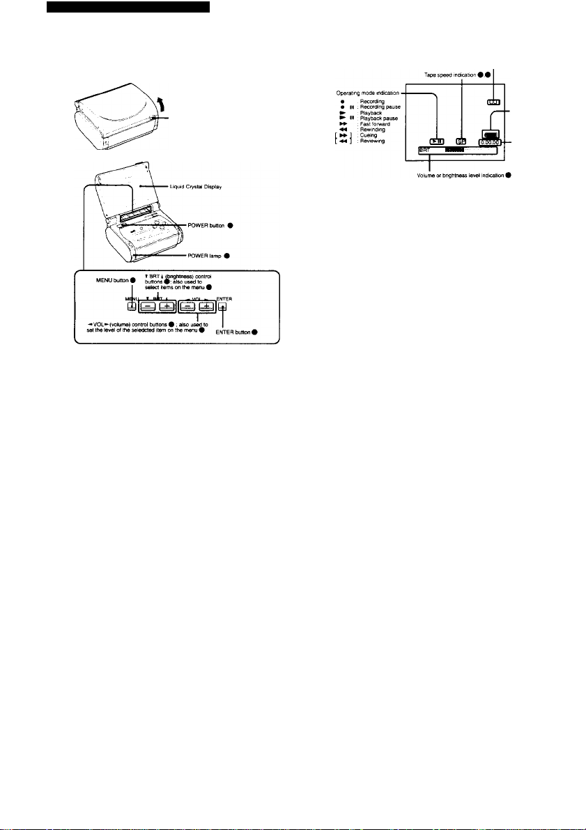
Location of Parts and Controls
For (details, refer to the pages indicated in circles.
Push OPEN A and pull up the display hrst.
Input/output irxiication 0
• Battery life indicaton #
VOL
BRT
Note
All indications are illustrated on one display as if they were actually displayed at the same time:
however, some of them are not displayed at the same time.
Page 5
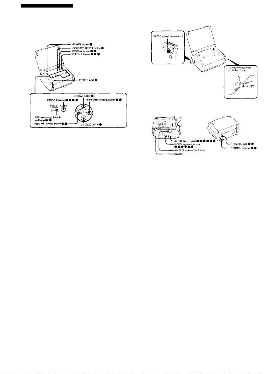
Location of Parts and Controls
J
Page 6
Power Sources
You can select the best power source tor your own r>ee<ls.
! Outdoors Battery pack
Power tource
» To a wall outlet
NP-55H (supplied)
ff
NP-55H
Only ihe AC-S10 anO the NP-55H are supplì
from your Sony òealer
Disconnecting the power source during recording or playback operations may damage ihe inserted
cassette tape. If this should happen, supply power again immediately and turn on the power
*P-77H
accessories for your special needs are available
Use the supplied AC-S10 AC power adaptor.
3 Align the upper side edge ol the connecting plate with the white line printed on the video
recorder/monltor^o that the slots ot the connecting ptete (the other end of the connecting
cord) are positioned over the tabs of Ihe battery mounting surfece.
4 Press the connecting plate and allde it in the direction of the ^ m
To remove the connecting plate
Slide out the connecting plate while sliding the BATT release knob.
CAUTION
TO PREVENT ELECTRIC SHOCK, DO NOT USE THIS POLARIZED AC PLUG WITH AN EXTENSION
CORD, RECEPTACLE OR OTHER OUTLET UNLESS THE BLADES CAN BE FULLY INSERTED TO
PREVENT BLADE EXPOSURE.
• The unit IS not disconnected from the AC power source as iong as it is connected to a wall outlet.
• One blade ot the plug is wider than the other lor Ihe purpose of safety and will f>i into a wait outlet only
one way. It you are unable to insert the plug fully into the outlet, contact your dealer
• While the unit is m use. particularly during charging, keep it away from AM receivers and video
eguipment because It will disturb AM reception and video operation. ....
Page 7

13влпщшBüÉiwjfPàaiht
То charge a battery pack
Befofe using a Danary раск, make sure to charge it first even
supplied NP-55H Dattery раек, optional NP-66H, NP-77HD a
on page 10. are avaiiaole.
Use Ihe suppliefl AC-SIO AC power aaaptor to charge a battery pack.
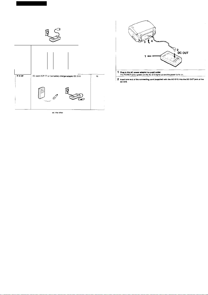
1 Plug in №• AC power adaptor to a wall outlet.
The POWER lamp (green) on the AC-St 0 (ignis up and the power tu
2 Inatall the battery pack in the AC-SIO.
Align me flat side of the battery pack with the line on the AC-St 0. Then push down and slide tne
battery pack m the direction of the arrow. The REFRESH lamp (red) lights up first and then it goes
out. When the CHARGE lamp (orange) lights up, battery charging begins When the battery is
charged, the CHARGE lamp goes out Unplug the AC power adaptor and the POWER larhp goes
out. (Refer to the instructions provided tor the AC-StO as well.)
NP-eSH
(supplied)
70 mm.
(Approx, mnjiss using AC-SIO)
• The battery pack cannot be charged when using the AC power adaptor is used to operate the unit
• An NP-S5H. NP-66H. NP-77HD or NP-77H battery pack can also be charged with the BC-StO or BC-77
battery charger.
To anach a battery pack to this unit
Align the upper side edge of the battery with the white line prinied on the video recorder/moniior so
that the slots of the battery are positioned over the tabs of the battery mounting surface, and slide the
battery pack while pressing it
NP-66H
100 mm. 140 ГТ11П.
NP-77H
NP-77HD
140 mm.
________
__________________________
To cheek the remaining battery capacity
When a battery pack i$ installed, press DISPLAY to show on th
I as well as other indications (see page 7 for other indications)
I To cancel this display, press DISPLAY again.
A fullycharged battery pack laatt lor:
Playback Approx. 70 m
Recording I Аррюх. 70 m
I To remove the battery pack
j
While slidirtg the ВАТТ release knob m the direction ot the ai
I
illustrated
Note
It you use the NP-77HD battery pack which has the battery hte indicator, the remaining battery capacity
intlicateO on tne LCD may be different trom that indicated by the NP-77HD battery pack. The indicator c
the NP-77HD battery pack is more accurate.
Approx. 106 m
Approx. 105 rn
• screen the remaining battery capacity
Approx. 140 m
; Approx. 140 m
Approx. 140 m
I Approx. 140 m
w, slide out (he battery pack a:
Page 8

Preparing battery packa
Prepare 2 or 3 timea more battery power then you plan to uae.
The published battery capacity is measured m a continuously playing VCR
at room lemperaiure starting with a fully charged battery. Fast winding or
rewinding uses much power than normal playing Conseguently, battery
consumption Oecomes taster whert these operations are performed
frequently.
Battery conaumption is faater in a cold climate
Cold climates reduce the efficiency of a battery and cause it to run out
more quickly
When to replace battery packs
When a battery pack is fully discharged, the POW€H lamp starts ohnking
slowly. Dunng recording, 'BATTERY' also starts lighting on the screen.
Replace the battery when the POWER lamp starts blinking rapidly
Turn off the video recorderfmonitor power before replacing the battery.
Especially during recording, keep the cassette inside the cassette holder
while replacing the battery. When a Iresh battery is attached, recording
can be resumed snnoothly without any picture distortion.
Notes on charging
Before using a battery pack, charge it fully A newly purchased battery
pack also needs to be charged before its first use.
Recharge a battery pack only whan it is fully uaed out
Avoid recharging only partly used battery packs. Reoealed charging of
partly discharged battery packs reduces their capacity and shortens their
overall life span. The original capacity can sometimes be recovered by
fully discharging and then fully recharging the battery pack.
Rechargeable battery packs
Battery pack care
• Remove the battery pack from the video recorder/monitor after use, and keep it m a cool place. When
the battery pack is installed on a video recorderrmcniior. a small amount of current flows to the recorder
even if the POWER switch is turned oft This causes overdiseharge and so shortens battery life.
• The battery pack is always discharging a little even when not in use Thus, the battery should be
charged before each use
• It the terminals (metal parts on the back! are dirty, the battery capacity wilt be reduced. When the
terminals are dirty, or when the battery pack has not been used for a long time, attach and remove it
several times. This will improve the contact between the battery pack and the video recorder/monitor
Also, wipe the ♦ and - terminals with a soft cloth or paper
• If the battery pack is not used fqr a long time (about 1 year) and you charge it again, the battery capacity
will be reduced. After several charging and discharging cycles, the battery will recover its onginal
capacity.
How to UM the switch on the battery pack
Use this switch as a reminder of charging.
Set the switch to the no-marked position when the charging is completed
Set the switch to the red-marked position when the battery is discharged.
Battery life
A battery can be fully charged and discharged about 500 in
lights up just after turning on the video recorder/monitor, ev
been instailed, replace the battery pack with a new one
Best temperature for charging
A lower temperature requires a longer charging time.
Charging under a temperature ranging from IC'D to 30°C (50°F to S6°F) is recommended.
Why a battery pack heats up
While a battery pack Is being charged or used, the chemical change occurring inside the battery pack
release heat. The battery pack becomes warm, but this Is normal anO not dangerous.
Warning
If the and • terminals are short-circuited with a piece of metal, the battery heats up abnormally. This
IS very dangerous. Never put an uncovered battery pack m a pocket together with a key holder or
other metals
9S under normal temperatures. If ‘'BATTERY'
1 though a fully charged battery pack has
___________________
______________________
__
Page 9

1 Attach the DC pack to the video recorder/monttor by aligning the upper side edge of the DC
pack with the white line on the video recorder/monitor and elide the DC pack in the direction .
of the ^ mark while preeeing It.
2 Plug the power cord into the cigarette lighter socket.
Notes
• Be careful not to let any metal object touch the metal projection on the battery pack. When the battery
pack IS not in use, keep <t in its case.
• Keep the video recorder/monitor away from any power source. Such sources may cause noise to appea
on the screen.
Cautions on using this unit in a car
• For your safety, do riot watch video tapes or operate the controls while driving.
• Avoid leaving the unit in a place with very high temperatures. If you do. it may cause distortion of the
cabinet or malfunction of the unit.
• If you use this unit while the car engine is stopped, the car battery will be discharged. Avoid runnir>g
this unit from the car battery more than 12 hours without recharging it.
• Remove the car bailery cord from the cigarette lighter socket if you do not use the unit for a long
Playing Back Tapes
Make Sure №at trie power source is attached to this ut
1 Press OPEN A and open the display.
. 2 Press EJECT*.
The cassette holder opens automatically
Do not open the cassette holder forcibly.
3 Insert a cassette with the window side fecirvg up.
4 Press the PUSH mark.
The cassette holder closes automatically.
When you press EJECT *. power Is supplied and the cassette holder opens even if me power <s turned
off. After the cassette holder opens, the power goes oft automaticaHy. Press POWER if you want to
continue the operation.
Page 10

Playing Back Tapes
! WilcWnfl WiMh TItMif'
1 Press POWER.
The POWER lamp lights.
fj PQWER^
The cassette hoiOer closes aytomatically.
Notes on opening and ctoslng it
• Do not insert your tinger into the cabinet while the cassette holder is open.
• Be caretui not to gel your finger caught m the cassette hoider.
Cassette care
• Store cassettes m their cases when they are not in use and keep them m
Oust and prevent uneven winding.
• Never insert a cassette upside down into the cassette holder.
• Never cover the small holes on the rear of a cassette or insert anything m
• Remove a cassette from the video recorder/momtor when it is not in use.
n upnght position to keep oi
) the small holes.
2 Insert a recorded taps (aes page 17).
3 Press > (ptay).
Playback starts.
4 Press BRT - or * and VOL - or + to adjust the brightness and the volume rsspectivsiy.
The bnghtness or volume level indication appears on the screen.
To stop playback
Press n ¡stop).
If power supply It intsrruptsd
The levels of bnghtnesa and volume are automabcally si
on the screen
T BRT 1 — VOL -
1 To rewind the tape
1 Press REW
EJECT
©
To advance the tape
Press FF ►».
le center point on the level indication tu
ii
Page 11

Playing Back Tapes
To turn off tfw power to this unit
Press POWER again so ttiat tne POWER lamp goes of(.
To rewind the tape and play It back automatically — Auto play
Press E> (play) while pressing REW ee.
To mute the pictures and sounds
Close the LCD SO that the LCD turns oH and sounds are not heard from the Speyer.
To restore the picture and sound, push OPEN & and pull the LCD up.
For private listening
Cortnect an earphone to the 0 (phones) lack. No sound will be heard from the speaker.
Vtttoiw PImkMfc ModM
To resume normal
playback, press O (play)
During I
playback |
To locate a particular
point wNIa viewing the
ptciure
— Picture aeareh
To view the picture et
high speed
— FR picture search
Whert the playtiack picture is viewed on another TV or monitor
Horizontal bands appear in picture search and FR picture search modes.
I Ounng I ^
I playback |
Dunng I
playback I
I During I PEW
I rewinding |
I Dunng I
I
torwardingl (»A
or PAUSE II. This mode
will be automatically
released and the unit will
stop after five minutes.
The menu screen appears.
Q
2 Press A or ▼ to select the item to ad)ust.
T BHT i
3 Press 4 or P to make adjustments.
Each time you press 4 ore. the seiected item is adfusted as shown below.
green^B red less depth A
4 PrsM ENTER. enter
To adjust the depth of colors
□
Page 12

Playing Back Tapes
The counter indicates the tape transport m hours, mirtutes and seconds.
Ounng playbacK or recording, it shows you the playback or recording lime
1 PrMaOISPUy.
The tape counter appears on the screen.
Recording or Editing Tapes
You can not record a TV progr^ since (hrs unit does not have a 0ui(t-m tuner However, you can edit a
tape with another VCR (8 mm, 8eta, or VHS format) connected through the VIOEO/AUOlO inputioutput
jacks ot this unit.
Editing from Another VCD
2 Press COUNTER RESET during playbeck or recording al tti
The counter 15 reset to 0:00:00.
Notts
• When you play back a blank tape, the tape counter does not tunction.
• The counter reading artd the point on the tape may not correspond exгtctly Use the counter as a guide.
• The dilferertce between the counter reading and the point on the tape may increase by several secortds
in №e lollowiitg cases;
- Alter repeated fast-torward and rewinding
- When playirrg back a tape recorded both m SP and LP modes
-When playing back a tape having a blank portion between recorded portions
It you want to locete later.
Hours Minutes Seconds
22
Page 13

Recording or Editing Tapes
I 4 Act/V4t0 Hm EOTT function' ff ft fs provfdsd with ttw ctfwr VCR.
I 5 Locals ths playback start point and prsss tha pause button on the other VCR.
I 6 Slide REC in ths direction of ths arrow and prsss PAUSEN on this unit.
This unit IS now put in recorOing pause mode.
7 Preee the p«uM button» (PAUSE N on thi» unit} on both units to reiesss ths pauses.
If you do not press PAUSE II again on this unit wihiin five minutes, the pause mode ot this ur
released automatically and this unit stops.
8 Press the pause buttons on both units to pause the units again.
9 Rapaai steps 7 and S to edit mora aceñas.
10 After editirvg ia comptatad, prase the stop buttons o on this unit) on both units to stop
I playback and recording.
• Although this unit does not have an EDIT lutKlion. using this functon on a VCR connected to this unit
lor dubbing will avoid detenoraiion of me picture on me duplicated tape.
When the tape is recorded to the end
The tape slops automatically, but me unit <$ not turned off. If you are not going to continue operation, turn
oft the power by pressing POWER.
When racordir>g from the beginning of tha tap#
Advance the tape (or about 15 seconds before recording. This will prevent missing the starling point when
pfayirvg bach on another VCR.
About recorded sound
Recording level is always fixed automatically.
The VOL - and ♦ have no effect on the recorded sound level.
ft power supply is Interrupted while recording
Recording stops.
Recording^layback time
Two tape speeds (SP/L.P) can be selected on the menu screen a
The recording lime in LP mode is twice as long as mat in SP mo<
recording in SP mode is recommended. During playback, the mo
IS selected automatically.
Difference in coior systeme
There are different formats of the TV color broadcast and eiecincity system NTSC, PAL and SECAM
Video cassette tapes are made to correspond to one of these formats. Use NTSC format cassette lapes
for this unit. You will find "P6" on the package of NTSC cassettes
To re-record on the cesMtte, slide the ts
Note
II you record, using this unit, on a tape that has been recorded with PCM sound, and then it you play ba
this tape on a VCR with PCM function, the sound may be cut off occasionally, if this happens, set the
audio monitor switch of the VCR to the standard position.
10 that red color is visible
Rear side ot a cassette
explained on page 23.
9. For better picture and sound,
le m which me lape has been recorded
Page 14

Recording or Editing Tapes
Conriect the REMOTE terminal on this unit and the CONTROL L
(he other VCR's LANC mode to 'M.'
PiayDacWpause on the other VCR and recordmgrpause on this ui
the other VCR Dy pressing only one button.
2 Press * or ▼ to select 'REC MODE."
3 Press ^ or ► to select "SP" or “LP.'
■« VOL
ENTER
Q
inal on the other VCR, and then st
n Be operated simultaneously Iron
4 Activate the EDIT luiKtIon It It it provided with the other VCfl.
5 Locate the playbacit at«t point and presa the pause button on the other VCR.
C in the direction of the arrow and press PAUSE N
IS now in recording pause mode
©
7 Press SYNCHRO EDIT on the other VCR to raleaee the pauae.
8 Prase SYNCHRO EDIT on the other VCR to psuee both units again.
9 Repeat steps 7 and 8 to edit other scenes.
i 10 After editing is completed, praea the stop buttons O Oh this unit) on both units to stop
I playback at>d recording.
About U <LANC)
1-ANC stands tor Local Applicalion Control Bus System. The LANC terminal is used for controlling the tape
transport of video equipment and peripherals connected to it This terminal has the same function as
those indicated as CONTROL L or REMOTE.
I
By adding an editing controller to the video equipment connected through the LANC terminals, ih
: various piece of equipmenf can be operated iviTh the controOer.
________________________________________________________________________________
Page 15

Recording or Editing Tapes
e other VCR is stereo type, use the VMC-910MS or VMC-920MS (not supplied)
vtoeoAWK) 1
The VIDEO/AUDIO input/outpul jacks automatically become ei
operating modes of this unit.
Relation between the operating mode and the input/output status
r input or output jacks according to the
AUDIO input/outpui
VIDEO input/outpu!
' 1 Turn on the power of t>oth unite.
2 Insert e source tape Into this unit (playback) and a tape for recording into the other VCR
(recording).
3 Select the tape apeed (SPA^) on the other VCR.
4 Activate the EDIT function if it ie provided with the other VCR.
5 Locate the playbacli start point artd press PAUSE N on this unit.
6 Put the other VCR Into recording pause mode
7 Press the pause buttons (PAUSE ■ on this unK) on both units to release the pause.
8 Press the pause buttons on both units to pause the units again.
I
9 Repeat steps 7 and 8 to edit more scenes.
; 10 After editing la completed, press the stop buttons (□ on this unit) on both units to stop
, playback and recording.
The current status will appear on the screen tor five seconds m the loilowing cases:
• When the status has changed
• When you press DiSPLAV
1
Page 16

Connecting Other Video Equipment
Vou can connect other equipmenl such as a TV, monrtor, video camera recorder, VCR, etc., through the
VlDEiyAODlO inpufoutput lacks.
For additional information, refer to the operating manuals of the eauipment you want to connect.
CowHctinB • 1V^ Monitor
RF OUT connector
zsTIFTl To your TV
If the VHF input terminal of your TV
IS a 300-Ohm tvnn-iead plug, use the
antenna seiector adaptor supplied
with the RFU tot.
Mote
The RFU-89UCKA includes tne following accessones.
• BFU adaptor (fl
• Antenna selector (1)
• Antenna selector adaptor(i)
To set the channel tor thia unit
To view the playback picture ot this unit, set the selector of the RFU adaptor to channel 3 oi
channel IS not active in your area, and select the same channel on the connected TV.
________
This allows you to monitor the pictures actually oeing ta
Video camera recorder
" If your video camera recorder is stereo type, use the VMC-910MS ot VMC-92QMS (notsuppwedl.
OOnWFttlli# V68l|/lt -«t.- . •
This allows you to edit tapes as explaihed Oefore. See pages 23 - 29
ÉÈÈm
Page 17

Maintenance
IWaWpe-' • -■, ,.v> /
• When the unit Is not used for a long period ot time, penoaically turn on me power and play bacK a tape
tor aoout three minutes.
• Clean the caDinei with a dry. soft cloth, or a soft cloth lightly moistened with a mild detergent solution. Do
not use any type ot solvent which may damage the limsh.
VW>o H—d Cl—ntng
To ensure a clear picture, clean the video heads periodically
It piayPacK pictures are noisy or hardly visible, the video heads rnay De contaminated. It this happens,
Clean ihe video heads with the Sony V8-2SCI-H cleamng cassette (not supplied) referring to the
instruciions supplied with it. ■■
Caution
Oo noi use commercially available wet-type cleaning cassettes
They may damage the video heads.
If fhe y8-25Cl-H cleartmg cassede is not available m yaur area, consult your Sony service facrlify.
Video Head Replacement
When playbacK pictures are not clear even after using the cleaning cassette, me video head may be
damaged. II this happens, the video head needs to be replaced with a new one. Consult your Sony
service facility tor replacing the video head.
Dull»lw UghilUgyilWII
A buiit-in lignting system is installed inside the liquid crystal screen ol this unit. Eventually the small
ifuorescertt tube used for this bui(t-irt itghtmg system wears out. ff the tube becomes drm or goes off
immediately aRar you lum on the unit, even with new Oattenes, replace me tube with a new one. To
replace the tube, cortsull the dealer where you purchased the unit, or a Sony service facility. The expected
life cf me small fluorescent tube is about three years if this unit is used for ah hour each day. Whan you
use this unit in a cold environment, the fluorescent tube will be dimmer at first. As soon as the temperafure
of the tube nses, it will regain its onginal bnghtness.
>t push the display forcibly
•It IS used m a coW place, a residual image may appear on the screen. This is not a maffurtct/on
^ nht points of light (red, blue, or green) may appear on me screen. This is not a malfunction
30
•i'.-v; ' r. ^ —,V .,v ■■
If this unit IS brought directly from a cold place to a warm place, moisture may condense msde the unit or
on the surface of the tape, if this happens. Ihe tape may siicK to the head drum, damaging both the tape
and me unit. Although this unit is furnished with a moisture sensor to prevent possible damage from
condensation, it cannot prevent damage if a tape is left inside the unit. R is best to remove the lape if you
are not using Ihe unit
If moisture condenses inside the unit
■DEW" appears on tha screen.
No button will function except EJECT
Elect (he cassette, tum off the unit and leave (he cassette hotder open for at (east an npur.
The unit can be used again if 'DEW" does not appear when one of the tape transport Duttons (D>, i~.
PAUSE M, FF ►► Of PIEW is pressed.
Page 18

Using Your Video Recorder/Wlonitor Abroad
It you prepare fulty charged battery packs and ttie suppkeC AC power adaptor (wbic/r can be used in aU
areas witti a Keal power supply ranging trom 100 V - 240 V), you can use your viOeo recofder/monitor m
any country. However, sitKe tr>e shape of the outlet differs widely m the world, you may need an AC plug
adaptor
Each country has special TV color broadcast and electricity systems. This unit is designed to play back
and record using the NTSC color video signals Playpack and recording of video sources of other color
signals (PAL and SECAM) cannot be guaranteed
Countries using NTSC color signal
Bahama islands. Canada, Central America. Japan, Korea. Mexico. Taiwan, the Philippines. U S A., etc.
Specifications
Video recording system
Audio recording system
Video signal
usable cassettes
Tape speed
Recording time
Fast forward/rewinding tit
LCD section
Picture
On-screen display
Inputs/outputs
VI06Q(AUDI0 irtpuVautput
Video input
Video output
Audio Input
Audio output
Speakers
Phones
tt REMOTE (LANC)
Generei
Power requirements
Power consumption
Operating temperature
Storage temperature
Dimensions
Weight
Accessories supplied
1
Roiary two-head helical scanmrrg FM system
Fixed head, monaural system
EIA standard, NTSC color
8 mm video format cassettes
SP approx 5 .43crr)/sec
LP: approx. 0.72 cm/sec
SP mode: 2 hours
LP mode: A noufS
(with Sony P6-120 cassette)
SP mode: 2 hours
LP mode; 4 hours
(with Sony P6-120 cassette I
Approx, a minutes
(with Sony P6-120 cassette)
3 inches measured diagonally
6.2 X 4.4 cm (2'/! X 1V. inches)
TN LCD/TFT active matrix method
Total dot number: 75,616 (324 x 234)
Selectab<e automatically accord«^ to the opetation
Phono lack, 1 Vp-p, 75 ohms, unbalanced, sync negative
Phono lack, t Vp-p. 75 ohms, unbalanced, sync negative
Phono (ack, -7.5 dBs (0 dBs=0.775 Vrms), input impedance
more than 47 xilohms
Phono jack, -7.5 dBs (330 mV) at load impedance 47 kiiohms,
ou^t impedance less than 10 kilohms
7.2 ohms, 150 mW
Miniiack. 6 ohms
Slereo mini-mini)ack
Battery mourning surface input: 6.0 V (battery pack),
7.5 V (AC power adaptor). 6 5 V (DC pack DCP-77)
5.8 W (for continuous playback)
0«C to 40“C (Зг^РЮ 104°F)
-20X to 60°C (-4°F to 140°F)
148.5x63x127 mm (wih/d)
(5Vt X 3Vs X 5 inches)
Approx. 940 g <1 lb I ог) not including Canary pack
Battery pack NP-55H(1)
AC power adaptor AC-siO (t)
Earphone (1)
i
wtipawii
Page 19

AC-S1Q
Power consumption
Power requirements
Output voltage
Battery onarge terminal:
Operating temperature
Storage temperature
Dimensions
Weight
Design and specifications are suOiect to change without notice.
20 W
100-240 VAC, 50/60 Hz
DC OUT- 7.5 V. t .6 A in operating mode
10 V. 1.3 A in charge mode
O’C to 40°C (32 F to 1(M=F>
-20°C to *SOV M F to )4£>-'F)
Approx, 72 X 39 X 141 mm (w/h/d)
(2'/e X t’/.6 X 5V« inchest including protecting parts and controls
Approx. 330g (12oz.)
List of HooofmiMndocI Accoooortoo-
I
NP-77HO, NP-77H, Or NP-66H
Car Battery charger
lC-SlOoreC-77
VMC-710M7720M (1 m/2 m)
36
23, 26. 27, 26
If you have a problem with this unit, first check the power supply source, then go through the list below
Delore calling the Sony service facility Should the problem persist, consult your Sony service facility.
Symptom
The unit does not work
even though the
POWER switch IS
turned on.
Power turns otf
1
automatically during
&
operation.
The battery pack is • The temperature is too low
quickly discharged. • The battery pack is worn out.
The playback picture is
not dear
?
Recording cannot be
1
1
i
The cassette cannot be
Ù,
e/eated.
The picture does not
appear.
u
The picture appears but ♦ Adjust the volume.
no sound IS heard • Disconnected the earphones.
No color
L_
PoMttM eausM шпО/ог comctloM
• The battery pack is not attached.
• The battery pack is exhausted.
Charge it (page 121
• AC power adaptor or car battery cord is disconnected.
* The battery pack is exhausted.
• The battery pack has not been charged tuHy
• The video heads may be contaminated. Clean me heads using the
Sony V8-25CLH cleaning cassette (not supphed).
• The video heads may be damaged.
Have the video heads replaced with new ones.
• The safety tab on the cassette is slid out to expose the red mark
• Moisture condensation has occurred.
• The tape is at its end.
• A cassette is not inserted.
• Moisture condensation has occurred
• No power IS supplied to the unit.
• The battery pack is exhausted
Use a fully charged battery, (page 12)
* Incorporated flouresceni tube is worn out.
• Adjust "COLOR" on the menu screen (page 2t).
Page 20

Warning Displayed on the Screen
The following indications appear on the screen indicating the operating environments and cautions
These indicaiions are not recorded on the tape. Out are generated by the unit and only exist on the
screen
Indication Meaning
Although you i
• No cassette
• The tape is i
• The red mark on the
cassette is exposed.
The battery is us
(seepage U|
1
 Loading...