

Page 1
SONY.
Trinitron® Color Video Monitor
GVM-1310
Operating Instructions page 2
Before operating the unit, piease read this manuai
thoroughiy and retain it for future reference.
Mode d’emploi page 12
Avant ia mise en service de cet appareil, prière de lire
attentivement ce mode d'emploi que l'on conservera pour
toute référence ultérieure.
3-753-817-21 (1)
i) 1991 by Sony Corporation
Page 2
Owner’s Record
Table of Contents
The model and serial numbers are located at the rear.
Record the serial number in the space provided below.
Refer to them whenever you call upon your Sony dealer
regarding this product.
Model No. GVM-1310
Serial No. .
WARNING
To prevent fire or shock hazard, do not ex
pose the unit to rain or moisture.
CAUTION
RISK OF ELECTRIC SHOCK
DO NOT OPEN
CAUTION : TO REDUCE THE RISK OF ELECTRIC SHOCK,
DO NOT REMOVE COVER (OR BACK).
NO USER-SERVICEABLE PARTS INSIDE.
REFER SERVICING TO QUALIFIED SERVICE PERSONNEL.
This symbol is intended to alert the
user to the presence of uninsulated
“dangerous voltage” within the prod
uct’s enclosure that may be of suffi
cient magnitude to constitute a risk of
electric shock to persons.
This symbol is intended to alert the
user to the presence of important
operating and maintenance (servicing)
instructions in the literature accompa
nying the appliance.
Precautions............................................................................3
Features.................................................................................3
Location and function os parts and controls...........................4
Specifications
Timing chart ........................................................................11
For the customers in the USA
This equipment has been tested and found to comply with
the limits for a Class A digital device, pursuant to Part 15 of
the FCC Rules. These limits are designed to provide
reasonable protection against harmful interference when the
equipment is operated in a commercial environment. This
equipment generates, uses, and can radiate radio frequency
energy and, if not installed and used in accordance with the
instruction manual, may cause harmful interference to radio
communications. Operation of this equipment in a
residential area is likely to cause harmful interference in
which case the user will be required to correct the
interference at his own expense.
You are cautioned that any changes or modifications not
expressly approved in this manual could void your authority
to operate this equipment.
For the customers in Canada
This apparatus complies with the Class A limits for radio
noise emissions set out in Radio Interference Regulations.
.........................................................................
8
Page 3

Precautions
Features
On safety
• Operate the unit only on 120 V AC.
• Should any solid object or liquid fall into the cabinet,
unplug the unit and have it checked by qualified personnel
before operating it any further.
• Unplug the unit from the wall outlet if it is not to be used for
several days or more.
• To disconnect the AC power cord, puli it out by grasping
the plug. Never pull the cord itself.
On Installation
• Allow adequate air circulation to prevent internal heat
build-up.
Do not place the unit on surfaces (rugs, blankets, etc.) or
near materials (curtains, draperies) that may block the
ventilation holes.
• Do not install the unit in a location near heat sources such
as radiators or air ducts, or in a place subject to direct
sunlight, excessive dust, mechanical vibration or shock.
On cloning
To keep the unit looking brand-new, periodically clean it with
a soft cloth. Stubborn stains may be removed with a cloth
lightly dampened with a mild detergent solution. Never use
strong solvents such as thinner or benzine, or abrasive
cleansers since these will damage the cabinet. As a safety
precaution, unplug the unit before cleaning it.
On repacking
Do not throw away the carton and packing materials. They
make an ideal container in which to transport the unit.
When shipping the unit to another location, repack it as
illustrated on the carton.
If you have any questions about this unit, contact your
authorized Sony dealer.
Note on equipment to be connected
A good-quality picture can be obtained when the GVM-
1310 is connected to equipment with the timing indicated
in the “Timing Chart” on page 11. If the monitor is
connected to equipment with the timing not indicated in the
chart, the picture quality may not be assured.
The GVM-1310 is a high-resolution color video monitor for
use with video or RGB video equipment. Monitoring RGB
signals of 15 kHz to 36 kHz horizontal scanning freqencies
and 50 Hz to 100 Hz vertical scanning frequencies, and
NTSC video signals is possible with one unit.
Multiscan color monitor
The monitor, which accepts 15 kHz to 36 kHz horizontal
scanning frequencies and 50 Hz to 100 Hz vertical scanning
frequencies, and detects the frequencies automatically, is
compatible with a wide range of video equipment.
VGA Auto size
The AUTO SIZE switch automatically fixes the right picture
size and picture center for a VGA signal from the D-sub 9pin input connector.
Analog/digital RGB multi connectors
Analog and digital RGB input signals can be fed through the
D-sub 9-pin and 25-pin multi connectors.
Compatible with RGB equipment using 64 colors (RGB A)
The monitor allows reproduction of 8, 16 or 64 color for
digital RGB input signals with the 16/64 or 8 COLOR
selector and by sync polarity.
RGB A SELECT connector
Input signals fed through the RGB A connector can be
selected with external equipment.
Automatic termination of the BNC-type video input
connector
The BNC-type video input connector is automatically
terminated at 75 ohms when no cable is connected to the
output connector. When a cable is connected to the output
connector, the signal input through the corresponding IN
connector is output from the output connector.
CONTROL S input connector
Connecting this connector to the CONTROL S output of
video equipment enables remote control operations of the
power on/off, input select, volume and picture settings
through the video equipment.
Y/C connector
A video signal split into the chrominance (C) signal and the
luminance (Y) signal can be input through this connector,
eliminating the interference between the two signals, which
tends to occur in a composite video signal, and also
assuring the picture quality.
Page 4
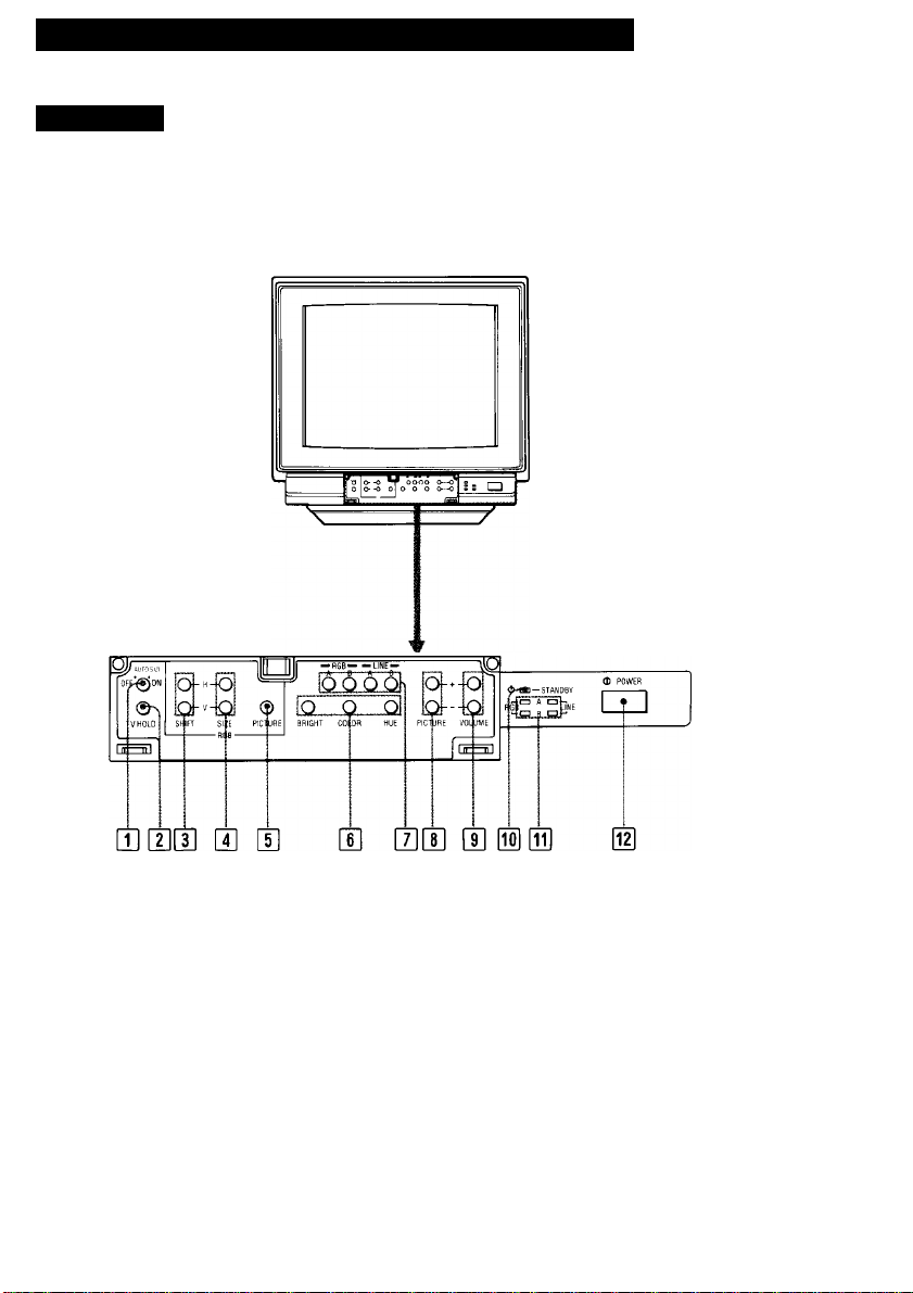
Location and Function of Parts and Controls
Front panel
Q] AUTO SIZE switch (only RGB A input)
ON: The right picture size and center are fixed in the
VGA modes. The H/V SiZE and HAf SHIFT
controls do not work. For other modes, the picture
size and phase are not guaranteed.
OFF: The HA/ SIZE and H/V SHIFT controls can be
freely set. The VGA modes have the same picture
size.
The above does not apply to RGB B input.
[T| V HOLD (vertical hold) control
If the video input picture rolls vertically, use this control
to stabilize it.
Control [|] does not function for RGB Input pictures.
Page 5

U] RGB H/V SHIFT (horizontal/vertical shift)
controls
Turn the H-SHIFT control to adjust the horizontal
position of the RGB input picture, it it is off center. Turn it
clockwise to shift the picture toward the right and
counterciockwise to shift the picture toward the left.
Turn the V-SHIFT control to adjust the vertical position of
the RGB input picture, if it is off center. Turn it clockwise
to shift the picture upward and counterclockwise to shift
the picture downward.
[U RGB H/V SIZE (horizontal/vertical size) controls
Turn the H-SIZE control to adjust the horizontal size.
Turn the V-SIZE control to adjust the vertical size.
[H RGB PICTURE control
Adjust this control it the picture level of RGB inputs
differs significantly from that of video inputs.
Turn this control clockwise to make the contrast and
color intensity of the RGB input picture stronger, or
counterclockwise to make them weaker.
• Controls H] to [|] function only for RGB input pictures.
However, they do not function when the RGB B input is
selected with the SUPERIMPOSE switch on the rear
panel set to ON.
• When turning the controls Q] to [J], use the supplied
screwdriver (attached to the panel cover).
[U Picture adjustment controls
BRIGHT (brightness) control
Normally keep this control at the center detent position.
Turn it clockwise to make the picture brighter or
counterclockwise to make it darker.
COLOR control
Turn this control clockwise to make the picture more
vivid or counterclockwise to make it paler.
HUE control
Use this control to obtain the most natural skin tones.
Turn it clockwise to add green to the skin tones or
counterclockwise to add purple/red hues.
[U Input select buttons
Press to select the input source to be monitored.
RGB A: for input signals fed through the RGB A
connector and the RGB A AUDIO jack
RGB B: for input signals fed through the RGB B
connector
LINE A: for input signals fed through the LINE A
connectors
LINE B; for input signals ted through the LINE B
connectors
[8] PICTURE +/- buttons
Press the + button to make the contrast and color
intensity stronger or press the - button to make them
weaker.
[U VOLUME +/- buttons
Press the + button for more volume or press the button for less volume.
® STANDBY Indicator
Lights when the power is turned off by remote control
through CONTROL S signal.
While the unit is operating, this indicator functions as the
response indicator.
It blinks when the VOLUME or PICTURE buttons are
pressed.
It lights steadily at the highest or lowest level of volume
or picture level.
OH Input select indicators
(RGB A/RGB B/LINE A/LINE B)
When the input source is selected, the corresponding
indicator lights.
@ POWER switch
Depress to turn on the monitor. Press again to turn it off.
The COLOR and HUE controls work for VIDEO signals
only.
Page 6

Location and Function of Parts and Controis
O
C)
® o @
[nj AC IN connector
Connect the supplied power cord.
0 LINE A
To monitor the input signal fed through this line input,
press the LINE A input select button on the front panel.
VIDEO IN connector(BNC type)
AUDIO IN jack(monaural)(phono type)
Connect to the video and audio outputs of video
equipment such as VCRs or video disc players.
For a loop-through connection, connect to the video and
audio outputs of another monitor.
VIDEO OUT connector(BNC type)
AUDIO OUT jack(monaural)(phono type)
For a loop-through connection, connect to the video and
audio inputs of another monitor.
When a connecting cord is connected to the VIDEO
OUT connector, the 75-ohm termination of the input is
automatically released and the signal input to the
VIDEO IN connector is output from this connector.
e/64 COLOR a DIGITAL
HO □□
Y/C 750
OFF [g ON
INauDIO oyj
8 COLOR CL ANALOG
[E oil (i [i BS oil
LINE B
To monitor the input signal fed through this line input,
press the LINE B input select button.
Y/C 75 n termination switch
When only the Y/C IN connector is connected (i.e.
nothing is connected to the Y/C OUT connector), set this
switch to ON.
When both Y/C IN and OUT connectors are connected
together for a loop-through connection, set this switch to
OFF.
Y/C IN connector(4-pin mini-DIN)
Connect to the Y/C output of video equipment.
AUDIO IN jack(monaural)(phono type)
Y/C OUT connector(4-pin mini-DIN)
For a loop-through connection, connect to the Y/C input
of another monitor.
AUDIO OUT jack(monaural)(phono type)
Page 7

[i^ RGB A interface unit
16, 64 COLOR/8 COLOR selector
Depress this selector when digital RGB equipment
having 16- or 64-color mode is connected to the RGB A
connector. The 16- or 64-color mode is automatically
selected by sync polarity. Keep the selector released for
digital RGB equipment having the 8-color mode.
DIGITAL/ANALOG selector
Depress this selector when video equipment having
digital RGB output is connected to the RGB A
connector. Release the selector for equipment having
analog RGB output.
RGB A connector (D-sub 9-pin)
Connect to video equipment having either digital or
analog RGB output.
To monitor the input signal fed through this connector,
press the RGB A input select button.
0 SUPERIMPOSE switch
Set this switch to ON (j=i) to display the composite video
signal from a laser disc player, etc., or to perform
superimposition. In this case, the RGB H/V SHIFT, RGB
HA/ SIZE and RGB PICTURE controls do not function.
Set this switch to OFF (n) to display the RGB signal
from a microcomputer, etc. In this case, the sync signal
should be supplied to pin 3 (H. sync) or pin 11 (V. sync)
of the RGB B connector.
' When the RGB B/NORMAL mode select signal is
supplied to pin 10 of the RGB B connector with the
SUPERIMPOSE switch set to ON, the previously
selected LINE A or LINE B indicator lights together
with the RGB B indicator.
I Synchronize the line signal of the video equipment that
is superimposing with the signal of RGB equipment.
RGB A AUDIO input jack (phono type)
Connect to the audio outputs of the RGB equipment
connected to the RGB A connector.
I RGB A SELECT connector (minijack)
When ground potential is applied to this connector,
signal input from the RGB A connector will be monitored
regardless of the setting of the input select buttons on
the front panel. If a power supply of 5 V is applied to the
connector or the circuit is open, the input signal selected
with the input select buttons will be monitored.
This connector allows the input source monitored to be
selected with external equipment.
] CONTROL S input connector (minijack)
Connect to the CONTROL S output of video equipment.
The power on/off, input select, volume and picture
settings can be remotely controlled through the
equipment connected.
Mutual interference of deflection may occur when
several monitors are ranged side by side tor a loopthrough connection, as this unit is compatible with the
signals of high horizontal frequencies. In such a
situation, allow adequate space between each unit.
] Earphone jacks
Phone 1 :When the earphone is connected,
Phone 2 (Switched) ;When the earphone is connected,
the sound through the speaker is
also audible.
the sound through the speaker is
not audible.
RGB B connector (D-sub 25-pin)
Connect to video equipment having either digital or
analog RGB output.
To monitor the input signal fed through this connector,
press the RGB B input select button.
7
Page 8

Specifications
Color system NTSC system
Picture tube Trinitron tube
Resolution Video inputs: 600 TV lines
Color temperature
Frequency response
Linearity
Line full range Composite video input
Overscan of the picture
Audio 0.5 W monaural
Anti-glare dark screen
Approx. 35.56 cm (13 inches) picture
measured diagonally, 90-degree
deflection
AG Pitch 0.25 mm
RGB inputs: 1024 dots x 768 lines
9300 К + 8MPCD
8 MHz (-6 dB, composite video)
30 MHz (-3 dB, RGB)
Horizontal: less than ±5%
Vertical; less than ±5%
Horizontal: 15.734 kHz ±500 Hz
Vertical; 50 to 60 Hz
RGB input
Horizontal: 15 to 36 kHz
Vertical: 50 to 100 Hz
Composite video input
less than +7%
RGB input
Horizontal: -7% to +5% variable
Vertical: -7% to +5% variable
Inputs VIDEO IN (LINE A): BNC connector (1)
Outputs VIDEO OUT (LINE A): BNC connector (1)
Power requirements
Power consumption
Operating temperature range
Humidity
Dimensions Approx. 379 x 365.1 x 411 mm (w/h/d)
Weight
Accessory supplied
Optional accessory
Design and specifications are subject to change without
notice.
composite video, 1 Vp-p ± 3dB, sync
negative, automatic termination at
75 ohms
Y/C IN (LINE B): 4-pin, mini-DIN (1)
Y(luminance signal): 1 Vp-p, sync
negative, 75-ohm termination
switchable
C (chrominance signal): 0.286Vp-p
(burst signal), 75-ohm termination
switchable
RGB A: D-sub 9-pin connector (1)
Analog RGB: 0.7Vp-p, 75 ohm
terminated
Digital RGB : TTL level
RGB B: D-sub 25-pin connector (1)
Analog RGB; 0.7Vp-p, 75 ohm
terminated
Digital RGB: TTL level
AUDIO IN (LINE A/LINE B/RGB A):
phono jack (3)
-5 dBs, high impedance
CONTROL S: minijack (1)
RGB A SELECT: minijack (1)
Y/C OUT (LINE B): 4-pin mini-DIN (1)
AUDIO OUT (LINE A/LINE B): phono
jack (2)
120 VAC, 50/60 Hz
95 vy Max.
0°C - 35°C (32°F - 95°F)
20% - 90%
(15x14Ye X 16V4 Inches)
Approx. 17 kg (37 lb 8 oz)
AC power cord (1)
D-sub 9-pin adaptor (1)
Display stand SU-552/W
Remote control unit RM-787
Earphone ME-20
8
Page 9
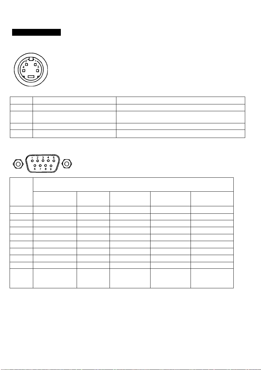
Pin assignment
Y/C (Y/C separate) IN connector (4-pin)
Pin No.
1 Y-input
2
CHROMA sub-carrier-input
3 GND for Y-input
4
GNDforCHROMA-input
RGB multi connector (9-pin)
Pin
No.
1 GND
2
3 R R R
4
5
6 (NC) (NC)
7
8 H/HV H/HV H/HV
9
Sync
level
GND: Ground
(NC): No connection
H: Horizontal sync
HV: Composite sync
r: Secondary red
Analog Digital
TTL level
(Positive or
Negative)
Signal Description
8-color
GND GND
(NC) (NC)
G
B
(NC) (NC) (NC)
V
R: Red
V: Vertical sync
I: Intensity
g: Secondary green
G G G
B B
V V
TTL level
(Positive or
Negative)
G: Green
B: Blue
b: Secondary blue
1 Vp-p, sync negative, 75 ohms
286 mVp-p, burst signal
Delay time between Y and C: within 0+100 nsec., 75 ohms
Ground
Ground
Signal
Digital
16-color
(NC)
1
TTL level
(HPositive
V:Positive)
Digital
64-color
GND
r
R
B
9
b
H/HV
V
TTL level
(HPositive
V:Negative)
Digital
monochrome
GND
(NC)
(NC)
(NC)
(NC)
1
G
H/HV
V
TTL level
(HPositive
V:Negative)
Page 10

RGB multi connector (25-pin)
000000000000
50000000000
5 16 17 18 19 20 21 22 23 24 25
Pin No.
1
IBM select
2
Audio select H (5 V or open): Audio inputs from #13
3 Video input
(composite video signal)
H. sync or composite sync
4
Blue input Positive polarity
5 Green input
6
Red input
7
NC
8
NC
9
Analog/digital mode select H (open): Analog signal (0.7 Vp-p)
10
RGB B/NORMAL mode select
(Function switch)
11
V.sync TTL level
12 Blanking input
13
Audio input Input level -5 dBs (normal), input impedance more than 47 kilo ohms
14
EXT/INT video select Functions with the SUPERIMPOSE switch set to ON.
15
Video input return
16
Blue input return
17 Green input return
18 Red input return
19 Ground
20 Video output
(composite sync output)
(
Signal Signal level
H (5 V): IBM mode L:3BitTTL
L (less than 0.4 V): Audio inputs from the LINE AUDIO IN jacks
When the high state is selected at #9:
1 Vp-p, 75 ohm terminated (Negative polarity sync),with the
SUPERIMPOSE switch set to ON
1.2-4 Vp-p, 75 ohm terminated (Negative or Positive), with the
SUPERIMPOSE switch set to OFF
When the low state is selected at #9: TTL level
When the high state is selected at #9:
Analog signal (0.7 Vp-p, 75 ohm terminated, non sync
1 Vp-p, 75 ohm terminated, with sync on G signal)
When the low state is selected at #9:
Digital signal (TTL level)
L (ground): Digital signal (TTL level)
H (3 V to 12 V): Signal input from the 25 pin D-sub
L (less than 2 V): Composite video inputs from LINE or Y/C
input impedance more than 22 kilo ohms
When the high state is selected at #9:
H (1 V to 3 V): RGB input from the 25 pin D-sub
L (less than 0.4 V): Composite or Y/C video inputs, 75 ohm terminated
(Rapid switch)
When the low state is selected at #9:
H (5 V or open): RGB input from the 25 pin D-sub
L (ground): Composite video input from LINE VIDEO IN
H (open): Sync signal input from #3
L (ground): Sync signal input from LINE or Y/ C
Output level 1.0 Vp-p, within sync 0.3 Vp-p output impedance 75 ohm
10
Page 11

Pin No.
21 Video output return
22 Audio common return
Audio output Output level -5 dBs (normal) output impedance less than 10 kilo ohm
23
24 Blanking input return
25 IBM luminance signal
Timing Chart
Sync
TJ
Signal
Positive polarity
When the high state is selected at #1: TTL level
When the low state is selected at #1: Low state (GND)
Horizontal Vertical
Signal level
Video
Sync
Sync
Polarity
fH
A(ps)
B (ps)
C(ps)
D (ps)
E (ps)
fV
F (ms)
G (ms)
H (ms)
I (ms)
J (ms)
H
V
CGA compatible
15.68 kHz
4.45 4.92 3.81 3.92
8.03 1.65 1.91 1.25
44.83 39.32 25.42 22.81
6.47
63.78
60 Hz 60 Hz
0.19 0.60 0.064 0.064
2.11 0.10 1.02 1.08 1.87 0.563/0.577
12.74
1.64 0.04
16.68 16.75 16.69
+
+
EGA compatible VGA compatible 1024x768 interlace
21.86 kHz
-0.14
45.75 31.78 28.15
60 Hz
16.01
15.26
0.349 0.416
+
- -
31.47 kHz 35.52 kHz
0.64 0.18
70 Hz 70 Hz 87 Hz
0.064
12.71 11.13 10.81
1,206 0/0,014
14.27 14.27
- -
+
+
-
0.113
11.50
+
+
11
 Loading...