

Page 1
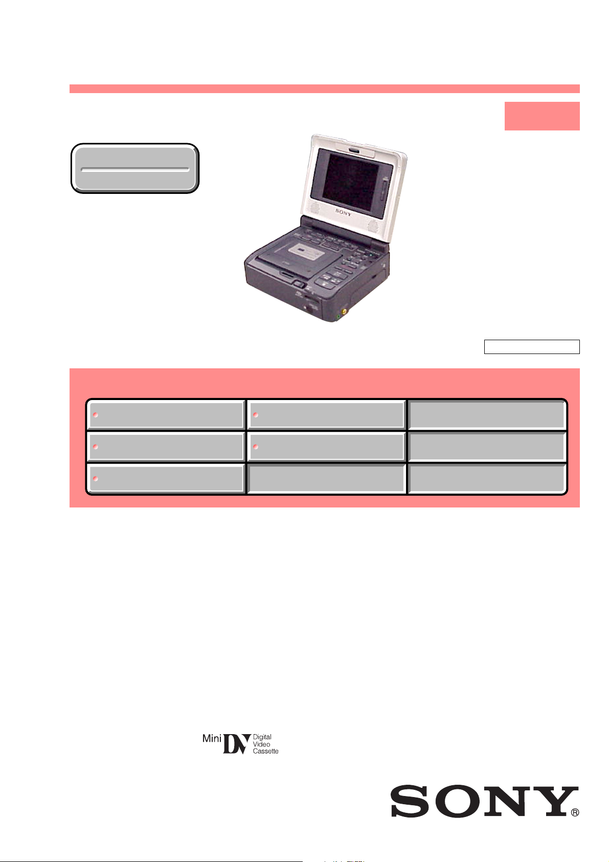
GV-D1000E
RMT-811
SERVICE MANUAL
Ver 1.0 2002. 01
Revision History
Revision History
Link
Link
SPECIFICATIONS
SPECIFICATIONS
DISASSEMBLY
DISASSEMBLY
LEVEL 1
AEP Model
UK Model
J200 MECHANISM
SERVICE NOTE
SERVICE NOTE
ORNAMENTAL PARTS
ORNAMENTAL PARTS
• For INSTRUCTION MANUAL, refer to separate file (992992972.pdf).
REPAIR PARTS LIST
REPAIR PARTS LIST
DIGITAL VIDEO CASSETTE RECORDER
Page 2
GV-D1000E
COVER
COVER
SPECIFICATIONS
VCR
System
Video recording system
2 rotary heads
Helical scanning system
Audio recording system
Rotary heads, PCM system
Quantization: 12 bits (Fs 32 kHz,
stereo 1, stereo 2),
16 bits (Fs 48 kHz, stereo)
Video signal
PAL colour, CCIR standards
Usable cassette
Mini DV cassette with the
mark printed
Tape speed
SP: Approx. 18.81 mm/s
LP: Approx. 12.56 mm/s
Recording/playback time (using
cassette DVM60)
SP: 1 hour
LP: 1.5 hours
Fastforward/rewind time (using
cassette DVM60)
Approx. 2 min.
Input/output
connectors
S video input
4-pin mini DIN
Luminance signal: 1 Vp-p, 75 Ω
(ohms), unbalanced
Chrominance signal: 0.3 Vp-p,
75 Ω (ohms), unbalanced
S video output
4-pin mini DIN
Luminance signal: 1 Vp-p, 75 Ω
(ohms), unbalanced
Chrominance signal: 0.3 Vp-p,
75 Ω (ohms), unbalanced
Audio/Video input
AV MINIJACK
Video: 1 Vp-p, 75 Ω (ohms),
unbalanced, sync negative
Audio: 327 mV, input impedance
more than 47 kΩ (kilohms)
Video output
Phono jack, 1 Vp-p, 75 Ω (ohms),
unbalanced, sync negative
Audio output
Phono jacks (2) 327 mV, output
impedance less than 1 kΩ
(kilohms)
DV jack
4-pin connector: S100
Headphone jack
Stereo minijack (ø 3.5 mm)
LANC jack
Stereo minijack (ø 2.5 mm)
USB jack
Mini-B
LCD screen
Picture
10 cm (4.0 type)
80.6 × 60.5 mm (3 1/4 × 2 1/2 in.)
Total dot number
123 200 (560 × 220)
General
Power requirements
8.4 V (AC power adaptor)
7.2 V (battery pack)
Average power consumption
During playback using LCD
5.2 W
During playback when you close
the LCD panel
3.5 W
Operating temperature
0 °C to 40 °C (32 °F to 104 °F)
Storage temperature
–20 °C to +60 °C (–4 °F to +140 °F)
Dimensions (Approx.)
148 × 65 × 133 mm
(5 7/8 × 2 5/8 × 5 1/8 in.)
(w/h/d)
Mass (approx.)
880 g (1 lb 15 oz)
excluding the battery pack and
cassette
Supplied accessories
See page 3.
AC power adaptor
Power requirements
100 - 240 V AC, 50/60 Hz
Output voltage
DC OUT: 8.4 V, 1.5 A in the
operating mode
Operating temperature
0 °C to 40 °C (32 °F to 104 °F)
Storage temperature
–20 °C to +60 °C (–4 °F to +140 °F)
Dimensions (approx.)
125 × 39 × 62 mm
(5 ×1 9/16 × 2 1/2 in.) (w/h/d)
excluding projecting parts
Mass (approx.)
280 g (9.8 oz)
excluding power cord
Design and specifications are
subject to change without notice.
— 2 —
Page 3
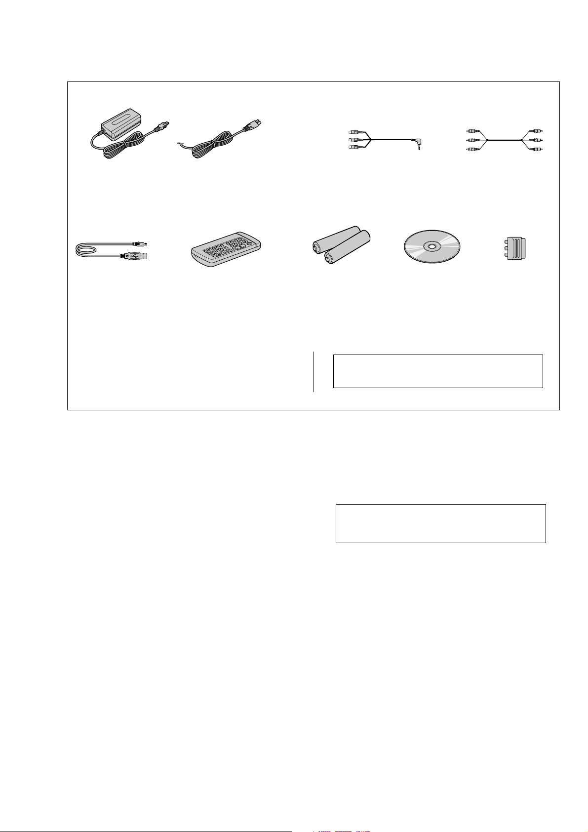
Checking supplied accessories.
Make sure that the following accessories are supplied with your camcorder.
GV-D1000E
AC power adaptor (1)
(AC-L10A)
0
1-475-599-11
USB cable (1)
1-757-293-11
Power cord (Mains lead)(1) (AEP model)
0
1-769-608-11
Power cord (Mains lead)(1) (UK model)
0
1-783-374-11
Wireless Remote Commander (1)
RMT-811
1-475-950-21
Lid, Battery Case (for RMT-811)
3-053-056-01
Other accessories
3-071-571-11 MANUAL, INSTRUCTION (ENGLISH/RUSSIAN)
3-071-571-21 MANUAL, INSTRUCTION (FRENCH/SPANISH) (AEP)
3-071-571-31 MANUAL, INSTRUCTION (GERMAN/DUTCH) (AEP)
3-071-571-41 MANUAL, INSTRUCTION (ITALIAN/PORTUGUESE) (AEP)
A/V converting cable (1.5m) (1)
1-790-690-11
Size R6 (AA) battery for
Remote Commander (2)
(not supplied)
Note : The components identified by mark 0 or dotted
line with mark 0 are critical for safety.
Replace only with part number specified.
CD-ROM
(SPVD-008
USB Driver)(1)
3-072-414-01
A/V connecting cable
(1.5m) (1)
1-757-334-11
21-pin adaptor (1)
1-573-291-11
SAFETY-RELATED COMPONENT WARNING!!
COMPONENTS IDENTIFIED BY MARK 0 OR DOTTED LINE WITH
MARK 0 ON THE SCHEMATIC DIAGRAMS AND IN THE PARTS
LIST ARE CRITICAL TO SAFE OPERATION. REPLACE THESE
COMPONENTS WITH SONY PARTS WHOSE PART NUMBERS
APPEAR AS SHOWN IN THIS MANUAL OR IN SUPPLEMENTS
PUBLISHED BY SONY .
SAFETY CHECK-OUT
After correcting the original service problem, perform the following
safety checks before releasing the set to the customer.
1. Check the area of your repair for unsoldered or poorly-soldered
connections. Check the entire board surface for solder splashes
and bridges.
2. Check the interboard wiring to ensure that no wires are
"pinched" or contact high-wattage resistors.
3. Look for unauthorized replacement parts, particularly
transistors, that were installed during a previous repair. Point
them out to the customer and recommend their replacement.
CAUTION :
Danger of explosion if battery is incorrectly replaced.
Replace only with the same or equivalent type.
4. Look for parts which, through functioning, show obvious signs
of deterioration. Point them out to the customer and
recommend their replacement.
5. Check the B+ voltage to see it is at the values specified.
6. Flexible Circuit Board Repairing
• Keep the temperature of the soldering iron around 270˚C
during repairing.
• Do not touch the soldering iron on the same conductor of the
circuit board (within 3 times).
• Be careful not to apply force on the conductor when soldering
or unsoldering.
— 3 —
Page 4

GV-D1000E
TABLE OF CONTENTS
SERVICE NOTE
1. POWER SUPPLY DURING REPAIRS ····························· 5
2. TO TAKE OUT A CASSETTE WHEN NOT EJECT
(FORCE EJECT) ································································ 5
SELF-DIAGNOSIS FUNCTION
1. SELF-DIAGNOSIS FUNCTION······································· 6
2. SELF-DIAGNOSIS DISPLAY ·········································· 6
3. SERVICE MODE DISPLAY ············································· 6
3-1. Display Method ·································································· 6
3-2. Switching of Backup No. ··················································· 6
3-3. End of Display···································································· 6
4. SELF-DIAGNOSIS CODE TABLE··································· 7
1. MAIN PARTS
1. ORNAMENTAL PARTS···················································· 8
2. DISASSEMBLY································································· 9
2-1. LCD CABINET ASSEMBLY·········································· 10
2-2. PD-130 BOARD, LS-56 BOARD ···································· 10
2-3. LCD WINDOW CABINET ASSEMBLY
(LCD901, ND901, SP901, SP902)··································· 11
2-4. BOTTOM CABINET ASSEMBLY, FP-571 FLEXIBLE
BOARD (V/L RECHARGEABLE BATTERY) ·············· 12
2-5. VC-275 BOARD ······························································ 12
2-6. BATTER Y TERMINAL BOARD ···································· 13
2-7. FP-575 FLEXIBLE BOARD (LANC), PR-41 BOARD,
IO-69 BOARD··································································13
2-8. MS-95 BOARD································································ 14
2-9. MECHANISM DECK······················································ 14
2-10. EJ-35 BOARD·································································· 15
2-11. EX-39 BOARD ································································ 16
2-12. MEMORY STICK CONNECTOR (10P),
FK-81 BOARD································································· 17
2-13. FP-602 FLEXIBLE BOARD (DV IN/OUT),
LCD BLOCK ASSEMBLY·············································· 18
2-14. HINGE UNIT, FP-569 FLEXIBLE BOARD··················· 19
3. REPAIR PARTS LIST ······················································ 20
3-1. EXPLODED VIEWS ······················································· 20
3-1-1.OVERALL SECTION······················································ 20
3-1-2.CABINET (UPPER) SECTION-1 ··································· 21
3-1-3.CABINET (UPPER) SECTION-2 ··································· 22
3-1-4.LCD SECTION ································································ 23
— 4 —
Page 5
GV-D1000E
)
COVER
COVER
SERVICE NOTE
1. POWER SUPPLY DURING REPAIRS
In this unit, about 10 seconds after power is supplied (8.4V) to the battery terminal, the power is shut off so that the unit cannot operate.
These following two methods are available to prevent this. Take note of which to use during repairs.
Method 1:
Use the DC IN terminal. (Use the AC power adaptor. (AC-L10, AC-VQ800 etc.))
Method 2:
Connect the adjustment remote commander RM-95 (J-6082-053-B) to the LANC jack, and set the HOLD switch to the “ADJ” side.
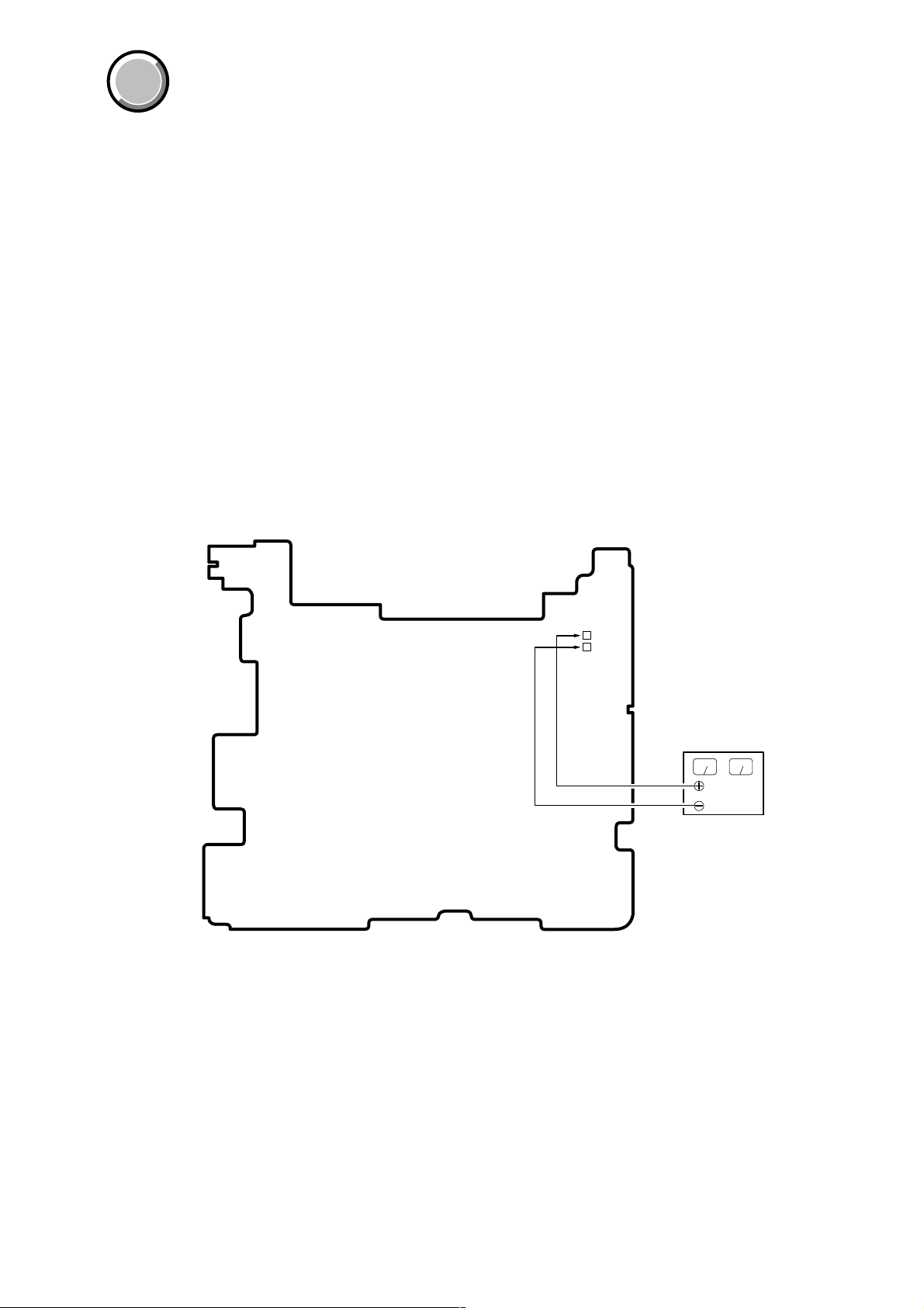
2. TO TAKE OUT A CASSETTE WHEN NOT EJECT (FORCE EJECT)
1 Remove the power supply (Battery or AC power adaptor).
2 Push the EJECT switch and open the cassette lid.
3 Refer to 2-4. to remove the cabinet (lid) assembly.
4 Refer to 2-4. to remove the cabinet (bottom) assembly.
5 Add 5V from the regulated power supply between ULD 5V + (Pin 3, 4 of CN936) and ULD 5V – (Pin 1, 2 of CN936), and unload
the cassette.
VC-275 board
ULD5V
+
–
Regulated
power supply (+5V
— 5 —
Page 6
GV-D1000E
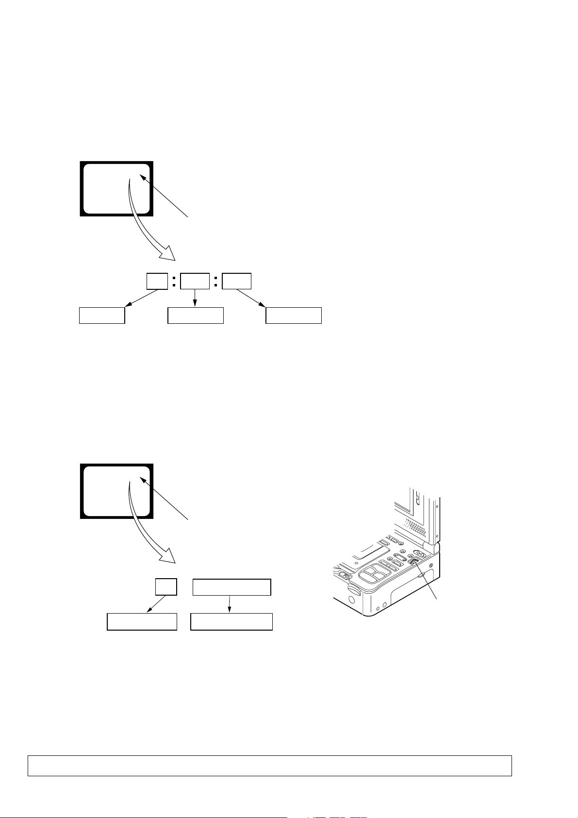
SELF-DIAGNOSIS FUNCTION
1. SELF-DIAGNOSIS FUNCTION
When problems occur while the unit is operating, the self-diagnosis
function starts working, and displays on the LCD screen what to
do. This function consists of two display; self-diagnosis display and
service mode display.
Details of the self-diagnosis functions are provided in the Instruction
manual.
LCD screen or monitor TV
C : 3 1 : 1 1
Blinks at 3.2Hz
1 1
Repaired by:
C : Corrected by customer
H : Corrected by dealer
E : Corrected by service
engineer
3 1C
Block
Indicates the appropriate
step to be taken.
E.g.
31 ....Reload the tape.
32 ....Turn on power again.
2. SELF-DIAGNOSIS DISPLAY
When problems occur while the unit is operating, the counter of the
LCD screen shows a 4-digit display consisting of an alphabet and
numbers, which blinks at 3.2 Hz. This 5-character display indicates
the “repaired by:”, “block” in which the problem occurred, and
“detailed code” of the problem.
Detailed Code
Refer to page 7.
Self-diagnosis Code Table.
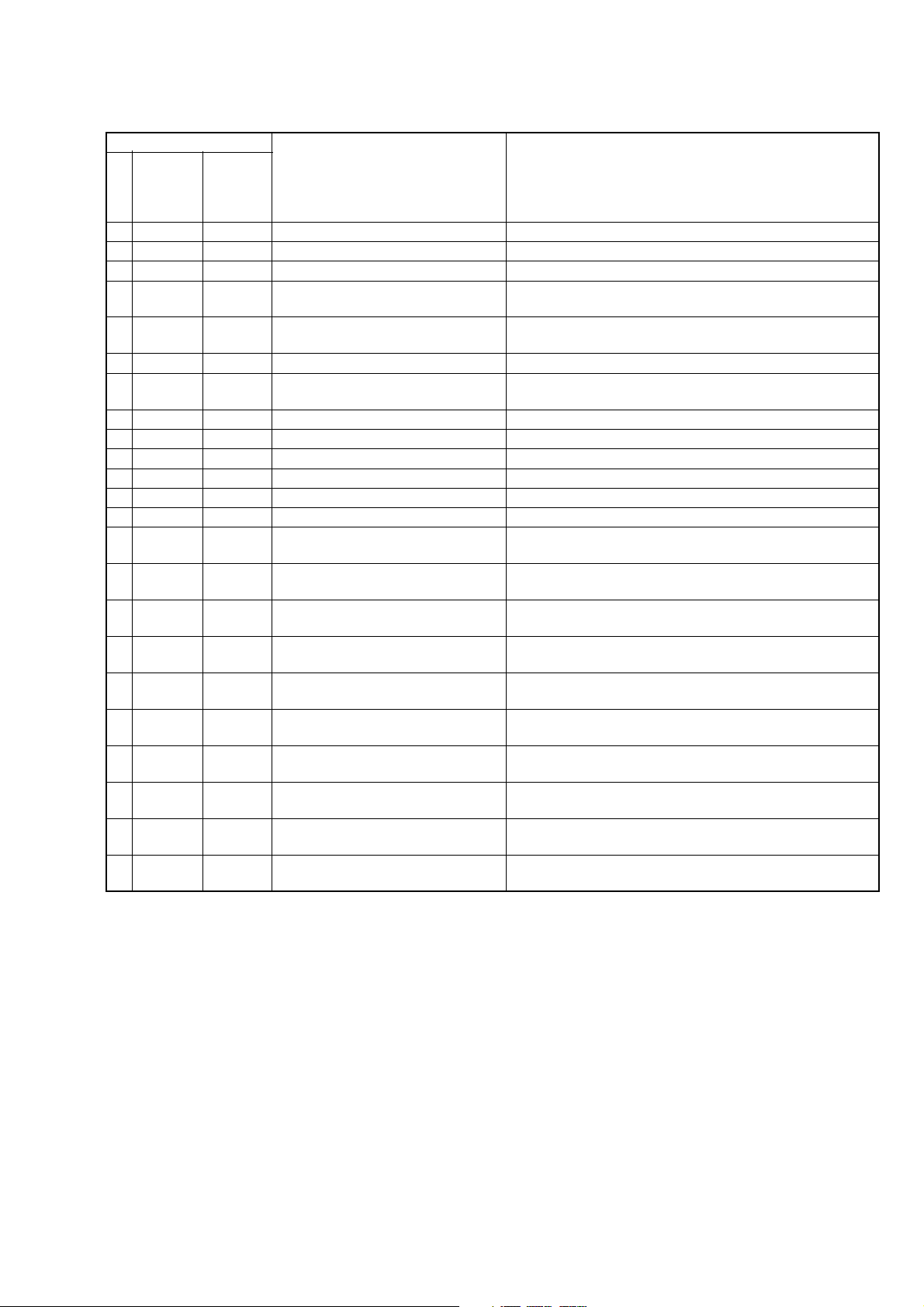
3. SER VICE MODE DISPLAY
The service mode display shows up to six self-diagnosis codes shown in the past.
3-1. Display Method
While pressing the “STOP” key , set the PO WER switch from OFF to ON, and continue pressing the “STOP” ke y for 10 seconds continuously .
The service mode will be displayed, and the counter will show the backup No. and the 5-character self-diagnosis codes.
LCD screen or monitor TV
[3] C : 3 1 : 1 1
Lights up
[3]
Backup No.
Order of previous errors
3-2. Switching of Backup No.
By rotating the control dial, past self-diagnosis codes will be shown in order. The backup No. in the [] indicates the order in which the
problem occurred. (If the number of problems which occurred is less than 6, only the number of problems which occurred will be shown.)
[1] : Occurred first time [4] : Occurred fourth time
[2] : Occurred second time [5] : Occurred fifth time
[3] : Occurred third time [6] : Occurred the last time
C : 3 1 : 1 1
Control dial
self-diagnosis codes
3-3. End of Display
Turning OFF the power supply will end the service mode display.
Note: The “self-diagnosis display” data will be backed up by the coin-type V/L rechargeable battery of FP-571 flexible board. When this coin-type
lithium battery is removed, the “self-diagnosis display” data will be lost by initialization.
— 6 —
Page 7
4. SELF-DIAGNOSIS CODE TABLE
Self-diagnosis Code
GV-D1000E
Repaired by:
C
C
C
C
C
C
C
C
C
C
C
C
C
C
C
C
C
C
C
C
C
C
C
Block
Function
04
21
22
31
31
31
31
31
31
31
31
31
31
31
31
32
32
32
32
32
32
32
32
Detailed
Code
00
00
00
10
11
20
21
22
23
24
30
40
42
10
11
20
21
22
23
24
30
40
42
Symptom/State
Non-standard battery is used.
Condensation.
Video head is dirty.
LOAD direction. Loading does not
complete within specified time
UNLOAD direction. Loading does not
complete within specified time
T reel side tape slacking when unloading
Winding S reel fault when counting the
rest of tape.
T reel fault.
S reel fault.
T reel fault.
FG fault when starting capstan.
FG fault when starting drum.
FG fault during normal drum operations.
LOAD direction loading motor time-
out.
UNLOAD direction loading motor
time-out.
T reel side tape slacking when
unloading.
Winding S reel fault when counting the
rest of tape.
T reel fault.
S reel fault.
T reel fault.
FG fault when starting capstan.
FG fault when starting drum
FG fault during normal drum
operations
Correction
Use the info LITHIUM battery.
Remove the cassette, and insert it again after one hour.
Clean with the optional cleaning cassette.
Load the tape again, and perform operations from the beginning.
Load the tape again, and perform operations from the beginning.
.
Load the tape again, and perform operations from the beginning.
Load the tape again, and perform operations from the beginning.
Load the tape again, and perform operations from the beginning.
Load the tape again, and perform operations from the beginning.
Load the tape again, and perform operations from the beginning.
Load the tape again, and perform operations from the beginning.
Load the tape again, and perform operations from the beginning.
Load the tape again, and perform operations from the beginning.
Remove the battery or power cable, connect, and perform
operations from the beginning.
Remove the battery or power cable, connect, and perform
operations from the beginning.
Remove the battery or power cable, connect, and perform
operations from the beginning.
Remove the battery or power cable, connect, and perform
operations from the beginning.
Remove the battery or power cable, connect, and perform
operations from the beginning.
Remove the battery or power cable, connect, and perform
operations from the beginning.
Remove the battery or power cable, connect, and perform
operations from the beginning.
Remove the battery or power cable, connect, and perform
operations from the beginning.
Remove the battery or power cable, connect, and perform
operations from the beginning.
Remove the battery or power cable, connect, and perform
operations from the beginning.
— 7 —
Page 8
GV-D1000E
)
1. MAIN PARTS
Note:
COVER
COVER
• Follow the disassembly procedure in the numerical order given.
• Items marked “*” are not stocked since they are seldom required for routine service.
Some delay should be anticipated when ordering these items.
• The parts numbers of such as a cabinet are also appeared in this section.
Refer to the parts number mentioned below the name of parts to order.
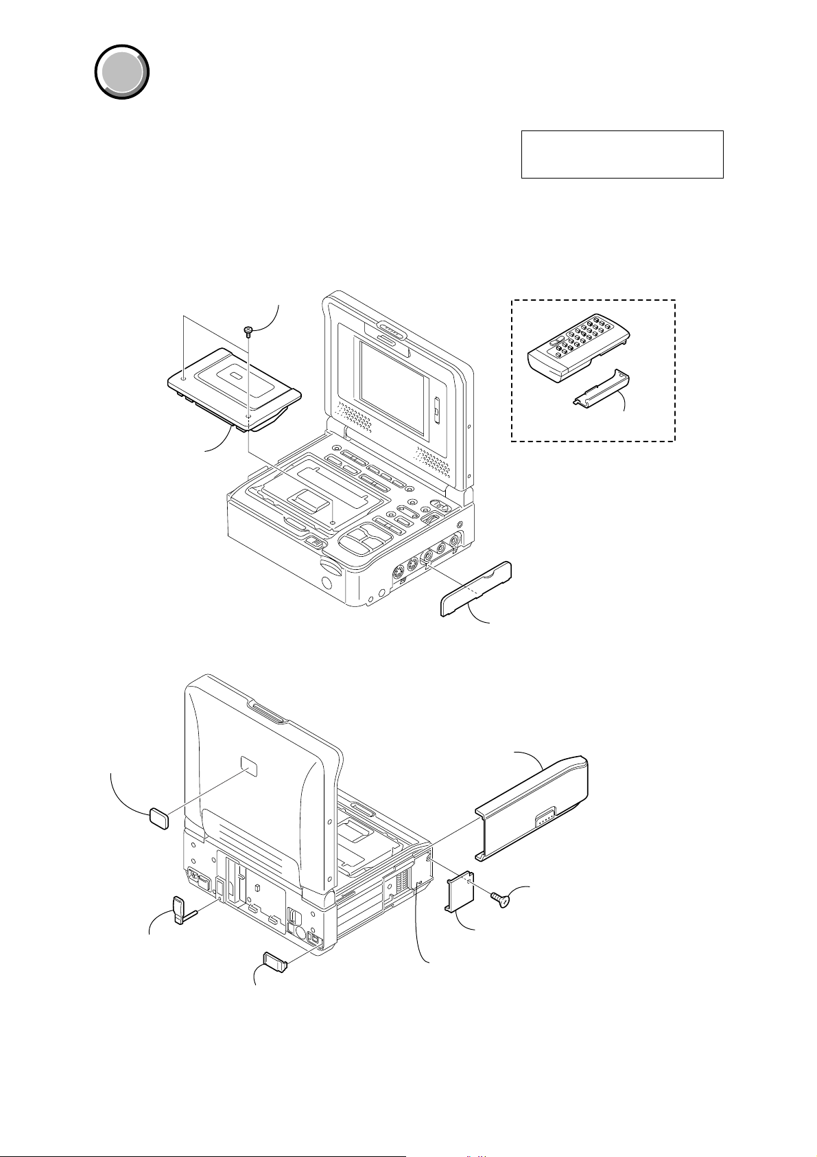
1. ORNAMENTAL PARTS
Two MI screws
(M2 × 4) (H)
3-067-347-01
Cassette lid assembly
X-3952-182-1
The components identified by mark 0 or
dotted line with mark 0 are critical for safety.
Replace only with part number specified.
Remote commander (RMT-811)
1-475-950-21
Battery case lid (for RMT-811)
3-053-056-01
MS mark
3-055-366-01
Terminal cover (DC)
3-072-524-01
Terminal cover (DV)
3-072-537-01
Jack lid
3-072-561-21
Cabinet lid assembly
X-3952-179-1
Tapping screw
(+k 2 × 6)
7-685-204-19
Lithium lid
3-072-566-01
FP-571 flexible board (4P) (V/L rechargeable battery
Note: Disassembling the main unit
is necessary to replace it.
— 8 —
Page 9

COVER
COVER
2. DISASSEMBLY
The following flow chart shows the disassembly procedure.
2-1. LCD cabinet assembly (See page 10)
2-2. PD-130 board, LS-56 board (See page 10)
2-3. LCD window cabinet assembly
(LCD901, ND901, SP901, SP902) (See page 11)
2-4. Bottom cabinet assembly, FP-571 flexible board
(V/L rechargeable battery) (See page 12)
GV-D1000E
GV-D1000E
2-5. VC-275 board (See page 12)
2-8. MS-95 board (See page 14)
2-9. Mechanism deck (See page 14)
2-10. EJ-35 board (See page 15)
2-11. EX-39 board (See page 16)
2-6. Battery terminal board (See page 13)
2-7. FP-575 flexible board (LANC),
PR-41 board, IO-69 board (See page 13)
2-12. MS connector, FK-81 board (See page 17)
2-13. FP-602 flexible board (DV IN/OUT),
LCD block assembly (See page 18)
2-14. Hinge unit , FP-569 flexible board
(See page 19)
— 9 —
Page 10

GV-D1000E
NOTE: F ollo w the disassembly procedure in the numerical order given.
2-1. LCD CABINET ASSEMBLY
2 Two screws (M2 × 4),
lock ace, p2
3 Two screws (M2 × 3),
lock ace, p2
4 Two
claws
6 Remove the LCD cabinet assembly
in the direction of the arrow.
1 Two screws (M2 × 4),
lock ace, p2
5 Two
claws
2-2. PD-130 BOARD, LS-56 BOARD
4 Harness (EP-51) (2P)
2 Two tapping screws
(B2 × 6)
3 FP-569 flexible
board (26, 32P)
9 Three screws (M2 × 3),
lock ace, p2
PD-130
Board
0 Remove the PD-130 board
in the direction of the arrow.
1 Harness (PL-53) (2P)
qd LS bracket
qf LS-56 board
qs Screw (M2 × 3),
lock ace, p2
qa Screw (M2 × 3),
lock ace, p2
5 SP902 (2P)
7 ND901 (10P)
8 LCD901 (24P)
6 SP901 (2P)
— 10 —
Page 11

2-3. LCD WINDOW CABINET ASSEMBLY (LCD901, ND901, SP901, SP902)
1 Two tapping screws
(B2 × 6)
2 Two tapping screws
(B2 × 6)
GV-D1000E
5 PD frame
6 LCD901
7 Two claws
9 ND901
4 LCD ground plate
3 Screw (M2 × 3),
lock ace, p2
8 Two claws
REMOVING THE LCD WINDOW
CABINET ASSEMBLY (SP901, 902)
3 SP ground plate
4 SP902
2 Remove the SP ground plate
in the direction of the arrow.
Dowel
Claw
1 Tapping screw
(B2 × 6)
5 Tapping screw
(B2 × 6)
6 SP ground plate
7 SP901
8 LCD window cabinet
assembly
— 11 —
Page 12

GV-D1000E
2-4. BOTTOM CABINET ASSEMBLY, FP-571 FLEXIBLE BOARD (V/L RECHARGEABLE BATTERY)
7 Bottom cabinet assembly
4 Three MI screws
(M2 × 4) (H)
6 Open the jack lid assembly
in the direction of the arrow B.
B
5 MI screw
(M2 × 4) (H)
2 Press the release button to remove
the cabinet lid assembly in the
direction of the arrow A.
0 FP-571 flexible board (4P)
(V/L rechargeable battery)
3 Three MI screws
(M2 × 4) (H)
A
Board
VC-275
8 Tapping screw
(+k 2 × 6)
2-5. VC-275 BOARD
9 Three screws (M2 × 3),
lock ace, p2
qa Remove the VC-275 board
in the direction of the arrow.
1 Two FP-404 flexible boards
(60P)
2 FP-570 flexible board
(40P)
C
1 Open the LCD panel little.
9 Remove the lithium lid in the
direction of the arrow C.
A
A
B
B
C
C
D
0 Three screws (M2 × 3),
lock ace, p2
qf DBB button
qd Switch cover assembly
D
qs Claw
7 FP-569 flexible board
(26, 32P)
8 FP-247 flexible board
(50P)
3 Harness (PL-53)
4 FP-602 flexible board
(5P)
5 Flexible flat cable
(5P)
— 12 —
6 Harness (EP-51)
A Flexible board (from DRUM HEAD) (10P)
B Flexible board (from MD MOTOR) (10P)
C Flexible board (from MD SENS) (27P)
D Flexible board (from MD CAP) (27P)
Page 13
2-6. BATTERY TERMINAL BOARD
y
GV-D1000E
3 Battery frame
5 Battery terminal board
4 Battery panel assembl
2 Two MI screws
(M2 × 4) (H)
1 MI screw
(M2 × 4) (H)
2-7. FP-575 FLEXIBLE BOARD (LANC), PR-41 BOARD, IO-69 BOARD
1 Three tapping screws
(B2 × 6)
8 Board to board connector
(10P)
7 Screw (M2 × 3),
lock ace, p2
9 PR-41 board
3 Five tapping screws
(B2 × 6)
qa Screw (M2 × 3),
lock ace, p2
A
2 FP-247 flexible board
(50P)
qs Jack frame
6 FP-575 flexible board (6P)
5 Screw (M2 × 3),
lock ace, p2
Note: To remove the IO-69 board,
remove the PR-41 board beforehand.
0 Two MI screws
A
(M2 × 4) (H)
qd IO-69 board
(Note)
4 Cabinet (R)
— 13 —
Page 14

GV-D1000E
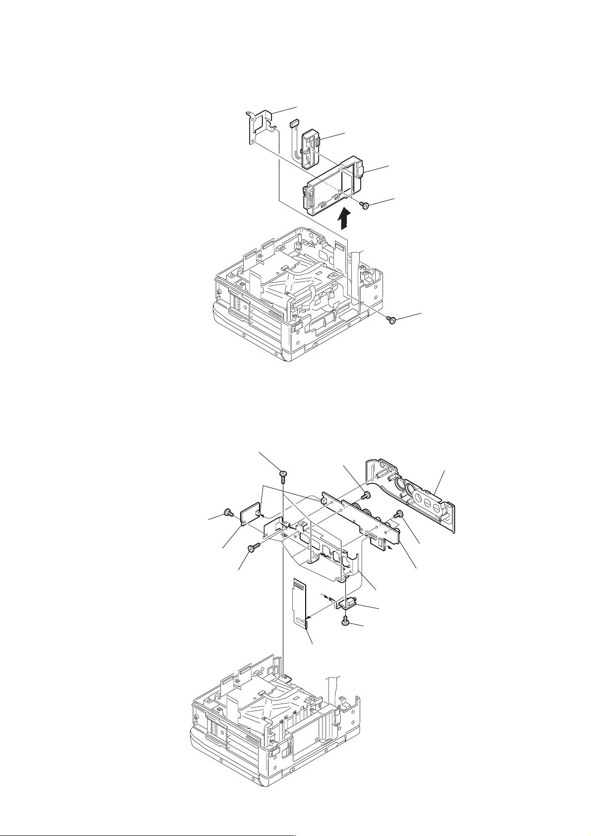
2-8. MS-95 BOARD
3 Two FP-404
flexible boards (60P)
2 Two screws (M2 × 3),
lock ace, p2
4 MS-95 board
1 FP-405 flexible board
(10P)
2-9. MECHANISM DECK
1 Screw (M2 × 3),
lock ace, p2
3 Harness (EX-CB)
4 Two tapping screws
(B2 × 6)
6 Tapping screw
(B2 × 6)
qg Mechanism deck
qf Cassette compartment
cover
2 Screw (M1.4 × 1.5)
qa Three screws (M1.4 × 1.5)
A
5 Tapping screw
(B2 × 6)
qs MD frame
8 Ferrite bead
A
0 FC holder
7 FP-405 flexible board
(10P)
PRECAUTION DURING
INSTALLATION
MD frame
Ferrite bead
FC holder
9 Screw (M2 × 3),
lock ace, p2
qd Two screws (M1.7 × 3),
lock ace, p2
— 14 —
Page 15

2-10. EJ-35 BOARD
y
2 Cassette lid assembly
GV-D1000E
1 Two MI screws
(M2 × 4) (H)
A
3 Press the cassette EJECT button
in the direction of the arrow A
and open the Lid frame assembly.
6 Harness (PL-53)
8 EJ-35 board
7 Screw (M2 × 3),
lock ace, p2
4 Four tapping screws
(B2 × 6)
5 Lid frame assembl
— 15 —
Page 16

GV-D1000E
y
2-11. EX-39 BOARD
1 Tapping screw
(B2 × 6)
4 FP-570 flexible board
3 Lid lock assembl
9 EX-39 board
7 Two screws (M2 × 3),
lock ace, p2
2 Two MI screws
(M2 × 4) (H)
5 MI screw
(M2 × 4) (H)
8 EX frame
6 Harness (EP-51)
— 16 —
Page 17

2-12. MEMORY STICK CONNECTOR (10P), FK-81 BOARD
d
4 Four tapping screws
(B2 × 6)
GV-D1000E
1 Three screws (M1.7 × 3),
lock ace, p2
3 Memory stick connector (10P)
2 FP-405 flexible boar
(10P)
7 FK frame
8 FK-81 board
6 Three screws (M2 × 3),
lock ace, p2
5 Flexible flat cable
(FFC-322) (10P)
— 17 —
Page 18

GV-D1000E
2-13. FP-602 FLEXIBLE BOARD (DV IN/OUT), LCD BLOCK ASSEMBLY
8 Hinge retainer bracket
4 Hinge retainer bracket
(L)
(R)
5 FP-602 flexible board
(5P)
3 Two screws (M2 × 3),
lock ace, p2
qa Remove the LCD block
assembly in the direction
of the arrow A.
9 Claw
2 Dowel
C
7 Two dowels
6 Two MI screws
(M2 × 4) (H)
1 Two MI screws
(M2 × 4) (H)
0 Claw
A
D
qg Shaft cover (R)
qd Remove the shaft cover (R), shaft cover
(L) in the direction of the arrow CD.
Claw
qf Shaft cover (L)
— 18 —
B
qs Open the LCD block
assembly in the direction
of the arrow B.
Page 19

2-14. HINGE UNIT, FP-569 FLEXIBLE BOARD
)
When attaching the hinge unit, wrap the
FP-569 flexible board hinge shaft as shown
while taking care so that the flexible board
must not be caught or pinched.
Hinge unit
FP-569 flexible
board (26, 32P)
Hinge shaft
GV-D1000E
3 FP-569 flexible
board (26, 32P)
4 Hinge unit
1 Two tapping screws
(B2 × 6)
LS-56 board
Hinge unit
Harness
(EP-51) (2P)
Hinge shaft
When attaching the hinge unit, route the
harness through the notch as shown while
taking care so that the harness must not
be caught or pinched.
2 Harness (PL-53) (2P
PD-130
Board
Harness (EP-51) (2P)
— 19 —
Page 20

GV-D1000E
COVER
COVER
3. REPAIR PARTS LIST
3-1. EXPLODED VIEWS
NOTE:
• -XX, -X mean standardized parts, so they may
have some differences from the original one.
• Items marked “*” are not stocked since they
are seldom required for routine service. Some
delay should be anticipated when ordering these
items.
3-1-1. OVERALL SECTION
ns : not supplied
• The mechanical parts with no reference number
in the exploded views are not supplied.
LCD section
8
(See page 23)
The components identified by mark 0 or
dotted line with mark 0 are critical for safety.
Replace only with part number specified.
8
9
7
E
8
Cabinet (upper)
section-1
(See page 21)
I
H
6
5
G
4
VC-275
Board
E
A
B
C
F
Mechanism deck
D
11
20
16
H
BT901
12
I
22
2
3
G
F
23
3
16
8
21
18
ns
ns
14
A
10
B
C
D
15
17
3
16
19
1
24
24
3
13
ns
8
Ref. No. Part No. Description Ref. No. Part No. Description
1 X-3952-164-1 CABINET (BOTTOM) ASSY
2 1-683-558-11 FP-404 FLEXIBLE BOARD
3 3-968-729-51 SCREW (M2), LOCK ACE, P2
4 not supplied MS-95 BOARD, COMPLETE (SERVICE)
5 1-667-399-11 FP-570 FLEXIBLE BOARD
6 X-3952-179-1 CABINET (LID) ASSY
7 X-3952-182-1 LID ASSY, CASSETTE
8 3-067-347-01 MI SCREW M2 (H)
9 X-3952-163-1 PANEL ASSY, BATTERY
10 3-072-524-01 COVER (DC), TERMINAL
11 3-072-565-01 FRAME, BATTERY
12 3-989-735-01 SCREW (M1.7), LOCK ACE, P2
13 3-072-561-21 LID, JACK
8
14 3-072-570-01 COVER, CASSETTE COMPARTMENT
15 X-3952-167-1 FRAME ASSY, MD
16 3-945-884-11 SCREW (2X6)
17 3-072-556-01 HOLDER, FC
18 1-500-227-31 BEAD, FERRITE
19 3-059-718-01 SCREW (M1.4X1.5)
20 X-3952-363-1 SWITCH COVER ASSY
21 1-959-237-21 HARNESS (EX-CB)
22 3-952-317-01 BUTTON, DBB
23 not supplied VC-275 BOARD, COMPLETE (SERVICE)
24 3-072-522-01 FOOT, RUBBER
BT901 1-694-772-21 TERMINAL BOARD, BATTERY
— 20 —
Page 21

3-1-2. CABINET (UPPER) SECTION-1
ns : not supplied
Cabinet (upper) section-2
(See page 22)
59
58
BT001
60
LCD section
(See page 23)
61
D
63
GV-D1000E
C
B
62
63
55
D
57
C
ns
56
A
68
B
55
67
68
A
63
55
55
54
53
51
52
: BT001 (V/L rechargeable battary) FP-571 flexible board on the mount position.
CAUTION :
Danger of explosion if battery is incorrectly replaced.
Replace only with the same or equivalent type.
64
65
66
Ref. No. Part No. Description Ref. No. Part No. Description
51 3-072-568-21 CABINET (R)
52 1-679-721-11 FP-247 FLEXIBLE BOARD
53 not supplied IO-69 BOARD, COMPLETE
54 not supplied PR-41 BOARD, COMPLETE
55 3-968-729-51 SCREW (M2), LOCK ACE, P2
56 3-072-569-01 FRAME, JACK
57 1-669-797-11 FP-602 FLEXIBLE BOARD
58 7-685-204-19 SCREW +KTP 2X6 TYPE2 NON-SLIT
59 3-072-566-01 LID, LITHIUM
60 1-667-400-11 FP-571 FLEXIBLE BOARD
61 3-064-401-11 COVER (L), SHAFT
62 3-064-402-11 COVER (R), SHAFT
63 3-067-347-01 MI SCREW M2 (H)
64 1-816-271-11 CONNECTOR, MEMORY STICK 10P
65 1-683-559-11 FP-405 FLEXIBLE BOARD
66 3-989-735-51 SCREW (M1.7), LOCK ACE, P2
67 1-667-404-11 FP-575 FLEXIBLE BOARD
68 3-945-884-11 SCREW (2X6)
BT001 1-528-724-21 BATTERY, V/L RECHARGEABLE
— 21 —
Page 22

GV-D1000E
3-1-3. CABINET (UPPER) SECTION-2
ns : not supplied
103
105
118
104
106
A
104
101
113
112
108
107
114
109
ns
104
111
110
A
116
115
117
101
ns
102
101
101
Ref. No. Part No. Description Ref. No. Part No. Description
101 3-945-884-11 SCREW (2X6)
102 3-072-564-01 FK FRAME
103 not supplied FK-81 BOARD, COMPLETE
104 3-968-729-51 SCREW (M2), LOCK ACE, P2
105 1-823-593-11 CABLE, FLEXIBLE FLAT (FFC-322)
106 X-3952-158-1 LOCK ASSY, LID
107 3-968-729-01 SCREW (M2), LOCK ACE, P2
108 3-072-537-01 COVER (DV), TERMINAL
109 X-3952-177-1 CABINET (UPPER) ASSY
110 3-072-563-01 FRAME, EX
111 not supplied EX-39 BOARD, COMPLETE
112 1-960-864-11 HARNESS (PL-53)
113 not supplied EJ-35 BOARD, COMPLETE
114 4-634-290-12 DAMPER
115 X-3952-159-1 FRAME ASSY, LID
116 7-624-104-04 STOP RING 2.0, TYPE -E
117 3-072-546-01 SPRING, EXTENSION
118 3-067-347-01 MI SCREW M2 (H)
— 22 —
Page 23

3-1-4. LCD SECTION
ns : not supplied
GV-D1000E
D
C
151
ns
153
E
SP901
152
153
154
170
B
A
ND901
155
156
LCD901
157
SP902
153
169
152
153
158
168
PD-130
Board
153
167
155
155
159
D
161
160
155
155
166
C
162
164
165
E
ns
B
171
A
163
160
Ref. No. Part No. Description Ref. No. Part No. Description
151 X-3952-180-1 CABINET ASSY, LCD WINDOW
152 3-064-405-01 PLATE, SP GROUND
153 3-948-339-61 TAPPING
154 3-064-400-01 SHEET (LCD BLIND)
155 3-968-729-51 SCREW (M2), LOCK ACE, P2
156 3-064-406-01 PLATE, LCD GROUND
157 3-064-403-01 FRAME, PD
158 not supplied PD-130 BOARD, COMPLETE
159 3-065-218-01 HINGE UNIT
160 3-968-729-71 SCREW (M2), LOCK ACE, P2
161 X-3952-181-1 CABINET ASSY, LCD
162 3-968-729-61 SCREW (M2X3), LOCK ACE, P2
163 3-945-884-11 SCREW (2X6)
— 23 —
164 1-960-864-11 HARNESS (PL-53)
165 3-064-404-01 BRACKET, LS
166 not supplied LS-56 BOARD, COMPLETE
167 1-667-398-11 FP-569 FLEXIBLE BOARD
168 1-958-004-11 HARNESS (EP-51)
169 3-064-766-01 SHEET (PD)
170 3-718-233-01 NUT, PLATE
171 3-055-366-01 MARK, MS
LCD901 not supplied INDICATOR MODULE, LIQUID CRYST
0 ND901 not supplied TUBE, FLUORESCENT,COLD CATHODE
SP901 1-505-862-71 SPEAKER (2.0 CM)
SP902 1-505-862-71 SPEAKER (2.0 CM)
Note : The components identified by mark 0 or dotted
line with mark 0 are critical for safety.
Replace only with part number specified.
Page 24

GV-D1000E
9-929-929-41
Sony EMCS Co.
— 24 —
2002A1600-1
©2002.1
Published by DI Customer Center
Page 25

Reverse
992992941.pdf
Revision History
Ver.
1.0
Date
2002.01
History
Official Release
Contents
—
S.M. Rev.
issued
—
 Loading...