

Sony DVW-790WSP, DVW-790WS, DVW-709WSP, DVW-709WS, DVW-707 User Manual
...
DIGITAL BETACAM CAMCORDER
DVW-707/707P
D VW-709WS/709WSP
/
D VW-790WS
SDI OUTPUT BOARD
BKDW-702
PICTURE CACHE BOARD
BKDW-703
IMAGE INVERTER BOARD
BKDW-704
790WSP
MAINTENANCE MANUAL Part 1
1st Edition (Revised 1)

! WARNING
This manual is intended for qualified service personnel only.
To reduce the risk of electric shock, fire or injury, do not perform any servicing other than that
contained in the operating instructions unless you are qualified to do so. Refer all servicing to
qualified service personnel.
! WARNUNG
Die Anleitung ist nur für qualifiziertes Fachpersonal bestimmt.
Alle Wartungsarbeiten dürfen nur von qualifiziertem Fachpersonal ausgeführt werden. Um die
Gefahr eines elektrischen Schlages, Feuergefahr und Verletzungen zu vermeiden, sind bei
Wartungsarbeiten strikt die Angaben in der Anleitung zu befolgen. Andere als die angegeben
Wartungsarbeiten dürfen nur von Personen ausgeführt werden, die eine spezielle Befähigung
dazu besitzen.
! AVERTISSEMENT
Ce manual est destiné uniquement aux personnes compétentes en charge de l’entretien. Afin
de réduire les risques de décharge électrique, d’incendie ou de blessure n’effectuer que les
réparations indiquées dans le mode d’emploi à moins d’être qualifié pour en effectuer d’autres.
Pour toute réparation faire appel à une personne compétente uniquement.
DVW-707 (SY) Serial No. 10001 and Higher
DVW-707P (SY) Serial No. 40001 and Higher
DVW-709WS (SY) Serial No. 10001 and Higher
DVW-709WSP (SY) Serial No. 40001 and Higher
DVW-790WS (SY) Serial No. 10001 and Higher
DVW-790WSP (SY) Serial No. 40001 and Higher
CAUTION
Danger of explosion if battery is incorrectly
replaced.
Replace only with the same or equivalent type
recommended by the manufacturer.
Dispose of used batteries according to the
manufacturer’s instructions.
Vorsicht!
Explosionsgefahr bei unsachgemäßem
Austausch der Batterie.
For the customers in the U.S.A. and Canada
RECYCLING NICKEL-CADMIUM
BATTERIES
Nickel Cadmium batteries are
recyclable. You can help preserve our
environment by returning your unwanted
batteries to your nearest point for
collection, recycling or proper disposal.
Note: In some areas the disposal of
nickel cadmium batteries in household or business trash
may be prohibited.
RBRC (Rechargeable Battery Recycling Corporation)
advises you about spent battery collection by the
following phone number.
Ersatz nur durch denselben oder einen vom
Hersteller empfohlenen ähnlichen Typ.
Entsorgung gebrauchter Batterien nach Angaben
des Herstellers.
ATTENTION
Il y a danger d’explosion s’il y a remplacement
incorrect de la batterie.
Remplacer uniquement avec une batterie du
même type ou d’un type équivalent recommandé
par le constructeur.
Mettre au rebut les batteries usagées
conformément aux instructions du fabricant.
ADVARSEL!
Lithiumbatteri-Eksplosionsfare ved fejlagtig
håndtering.
Udskiftning må kun ske med batteri
af samme fabrikat og type.
Levér det brugte batteri tilbage til leverandøren.
Call toll free number: 1-800-822-8837
(United States and Canada only)
Caution: Do not handle damaged or leaking nickelcadmium batteries.
Voor de klanten in Nederland
Dit apparaat bevat een MnO
back-up.
Raadpleeg uw leverancier over de verwijdering van de
batterij op het moment dat u het apparaat bij einde
levensduur afdankt.
Gooi de batterij niet weg. maar lever hem in als KCA.
Bij dit produkt zijn batterijen geleverd.
Wanneer deze leeg zijn, moet u ze niet
weggooien maar inleveren als KCA.
2-Li batterij voor memory


Table of Contents
Manual Structure
Purpose of this manual .............................................................................................. 5
Contents .....................................................................................................................6
Related manuals......................................................................................................... 6
1. Service Overview
1-1. Operating Conditions ..................................................................................1-1
1-2. Supplied Accessories ..................................................................................1-1
1-3. Main Part Locations and Circuit Functions ................................................1-2
1-3-1. Printed Circuit Board Locations................................................. 1-2
1-3-2. Circuit Functions ........................................................................ 1-4
1-3-3. Mechanical Part Locations ......................................................... 1-6
1-3-4. Sensor Locations and Functions................................................. 1-8
1-4. Matching Connectors ................................................................................1-10
1-5. Signal Inputs and Outputs .........................................................................1-11
1-6. Removing/Reinstalling Outside Panel ...................................................... 1-14
1-7. Opening/Closing Inside Panel...................................................................1-15
1-8. Removing/Reinstalling Cassette Compartment ........................................ 1-15
1-9. Removing/Reinstalling Plug-in Boards.....................................................1-17
1-9-1. DCP/DVP Board Assembly .....................................................1-17
1-9-2. SV-210 Board........................................................................... 1-17
1-10. Switch/Slit Land Settings and LED Functions on the Boards .................. 1-18
1-10-1. AXM-21 Board ........................................................................1-18
1-10-2. CNB-11 Board .........................................................................1-19
1-10-3. DCP-17 Board .......................................................................... 1-20
1-10-4. DVP-17 Board..........................................................................1-21
1-10-5. HN-260 Board .......................................................................... 1-22
1-10-6. TC-101 Board........................................................................... 1-23
1-10-7. TG-207 Board
(for DVW-790WS/790WSP/709WS/709WSP only)............... 1-24
1-10-8. DIF-75 Board (BKDW-702) ....................................................1-25
1-11. Ejecting the Cassette Tape Manually ........................................................1-26
1-12. Inserting the Cassette Tape With Outside Panel Removed....................... 1-27
1-13. Cleaning When the Heads are Clogged ....................................................1-27
1-14. Fixtures and Adjustment Equipment......................................................... 1-28
1-15. Battery for Memory Backup ..................................................................... 1-28
1-16. Replacing the DC-DC Converter ..............................................................1-28
DVW-790WS/709WS/707
DVW-790WSP/709WSP/707P P1
1

2. Diagnostics
2-1. Error Code ...................................................................................................2-1
2-1-1. Warning Indicators .....................................................................2-1
2-1-2. Error Codes ................................................................................2-1
2-2. Error Messages............................................................................................2-2
2-3. Display Panel and Lamp Operation Check .................................................2-2
2-4. Displaying the Servo Adjustment Data.......................................................2-3
2-5. Displaying the Slack Information in the Past.............................................. 2-4
3. Setup Menu
3-1. Engineer Mode (Setup Menu) .....................................................................3-1
3-1-1. Fundamental Operation of the Setup Menu ............................... 3-2
3-1-2. Contents of Setup Menu .............................................................3-3
3-1-3. Setup Menu List .......................................................................3-16
3-2. VTR (DIAG) Menu...................................................................................3-25
4. Camera System Electrical Alignment
(Only for DVW-790WS/790WSP/709WS/709WSP)
4-1. General Information for Electrical Adjustment .......................................... 4-1
4-1-1. Note for Adjustment...................................................................4-1
4-1-2. Equipment/Fixtures .................................................................... 4-1
4-1-3. Initial Setting for Switches .........................................................4-1
4-1-4. Maintaining the Grayscale Chart ...............................................4-3
4-2. ENC Level Adjustment ............................................................................... 4-5
4-3. TEST OUT Level Adjustment ....................................................................4-6
4-4. VA Gain Adjustment...................................................................................4-7
4-5. White Shading Adjustment .........................................................................4-8
4-6. Gamma Correction Adjustment .................................................................. 4-9
4-7. Black Set Adjustment................................................................................ 4-10
4-8. Flare Adjustment .......................................................................................4-11
4-9. Manual Knee and White Clip Adjustments ..............................................4-12
4-10. Crispening Adjustment (16:9)...................................................................4-13
4-11. Level Depandent Adjustment (16:9) .........................................................4-13
4-12. H/V Ratio Adjustment (16:9)....................................................................4-14
4-13. Detail Level Adjustment (16:9) ................................................................4-14
4-14. Crispening Adjustment (4:3).....................................................................4-15
4-15. Level Depandent Adjustment (4:3) ...........................................................4-15
4-16. H/V Ratio Adjustment (4:3)......................................................................4-16
4-17. Detail Level Adjustment (4:3) ..................................................................4-16
4-18. Skin Tone Adjustment...............................................................................4-17
4-19. Zebra Adjustment......................................................................................4-18
4-20. Automatic Iris Adjustment ........................................................................4-19
2
DVW-790WS/709WS/707
DVW-790WSP/709WSP/707P P1

5. Camera System Electrical Alignment
(Only for DVW-707/707P)
5-1. General Information for Electrical Adjustment .......................................... 5-1
5-1-1. Note for Adjustment...................................................................5-1
5-1-2. Equipment/Fixtures .................................................................... 5-1
5-1-3. Initial Setting for Switches .........................................................5-1
5-1-4. Maintaining the Grayscale Chart ...............................................5-2
5-2. ENC Level Adjustment ............................................................................... 5-4
5-3. TEST OUT Adjustment .............................................................................. 5-4
5-4. VA Gain Adjustment...................................................................................5-5
5-5. White Shading Adjustment .........................................................................5-6
5-6. Gamma Correction Adjustment .................................................................. 5-7
5-7. Black Set Adjustment.................................................................................. 5-8
5-8. Flare Adjustment .........................................................................................5-8
5-9. Manual Knee and White Clip Adjustments ................................................5-9
5-10. Crispening Adjustment...............................................................................5-10
5-11. Level Depandent Adjustment.....................................................................5-10
5-12. H/V Ratio Adjustment................................................................................5-11
5-13. Detail Level Adjustment ............................................................................5-11
5-14. Skin Tone Adjustment................................................................................5-12
5-15. Zebra Adjustment.......................................................................................5-13
5-16. Automatic Iris Adjustment .........................................................................5-14
6. Block Diagrams and Circuit Description
6-1. Circuit Description ...................................................................................... 6-1
6-2. Camera Overall Block Diagram..................................................................6-6
6-3. VTR Overall Block Diagrams..................................................................... 6-8
7. Periodic Maintenance and Inspection
7-1. Cleaning ...................................................................................................... 7-1
7-1-1. General Information for Cleaning .............................................. 7-1
7-1-2. Cleaning of Tape Running Surface of Upper Drum and
Video Heads ............................................................................... 7-3
7-1-3. Cleaning of Tape Running Surface of Lower Drum and
Lead Surface............................................................................... 7-4
7-1-4. Stationary Heads Cleaning ......................................................... 7-5
7-1-5. Cleaning of Tape Running System and Tape Cleaner ............... 7-6
7-1-6. Cares After Using at Special Environment ................................7-7
7-2. Periodic Check ............................................................................................7-8
7-2-1. Hours Meter ...............................................................................7-8
7-2-2. Periodic Check List .................................................................... 7-9
DVW-790WS/709WS/707
DVW-790WSP/709WSP/707P P1
3

8. Spare Parts
8-1. Notes on Repair Parts..................................................................................8-1
8-2. Recommended Replacement Parts ..............................................................8-2
9. Optional Boards Installation
9-1. BKDW-702 (DIF-75 board)........................................................................ 9-1
9-2. BKDW-703 (MY-93 board)........................................................................ 9-2
9-3. BKDW-704 (FM-65 board) ........................................................................ 9-4
4
DVW-790WS/709WS/707
DVW-790WSP/709WSP/707P P1

Purpose of this manual
Contents
Manual Structure
This manual is the Maintenance Manual Part 1 of the following models:
Digital Camcorder DVW-790WS/709WS/707,
DVW-790WSP/709WSP/707P
Sony SDI Output Board BKDW-702
Sony Picture Cache Board BKDW-703
Sony Image Inverter Board BKDW-704 (For DVW-790WS/790WSP/709WS/
709WSP only)
This manual is intended for use by trained system and service engineers, and
provides the information that is required to the primary services, maintenance of this
unit and installation of the optional boards (BKDW-702/703/704) .
This manual is organized by the following sections:
Section 1 Service Overview
Explains the locations of main parts, the functions of printed circuit boards, the
removal and reinstallation of cabinet, and the measures against troubles.
Section 2 Diagnostics
Explains the error messages and self-diagnostics.
Section 3 Setup Menu
Explains the setup menu (engineering mode) and VTR (DIAG) menu of this unit.
Section 4 Camera System Electrical Alignment
(Only for DVW-790WS/790WSP/709WS/709WSP)
Explains the electrical adjustments after installing/replacing the lens to/of the DVW790WS/790WSP/709WS/709WSP.
Section 5 Camera System Electrical Alignment
(Only for DVW-707/707P)
Explains the electrical adjustments after installing/replacing the lens to/of the DVW707/707P.
Section 6 Block Diagrams and Circuit Description
Describes the overall block diagrams and circuit description.
DVW-790WS/709WS/707
DVW-790WSP/709WSP/707P P1
Section 7 Periodic Maintenance and Inspection
Explains the cleaning procedures and periodic checks.
5

Related manuals
Section 8 Spare Parts
Describes the notes on spare parts and list of parts which need the periodic maintenance.
Section 9 Optional Boards Installation
Explains the installation procedure of optional boards (BKDW-702/703/704) to this
unit.
Besides this “Maintenance Manual Part 1”, the following manuals are available for
this unit:
..
. Operation Manual (Supplied with this unit)
..
This manual is necessary for application and operation of this unit.
..
. Maintenance Manual Part 2 (available on request)
..
Volume-1 : Service Instructions
Volume-2 : Parts List and Diagrams
These manuals describe the information that premises the parts level service
(adjustments, board layouts, schematic diagrams, detailed parts list, etc.) for this
unit.
If these manuals are required, contact your local Sony Sales Office/Service
Center.
..
. BVF-V10/V10CE or BVF-V20W/V20WCE
..
Maintenance Manual (available on request)
This manual describes the service information of the supplied viewfinder.
If this manual is required, contact your local Sony Sales Office/Service Center.
6
DVW-790WS/709WS/707
DVW-790WSP/709WSP/707P P1

Section 1
Service Overview
1-1. Operating Conditions
Operating temperature : 0 to 40 dC
Humidity : 25 to 85 % (Relative humidity)
Storage temperature : _20 to 60 dC
User under special environment (Measure for cold area) :
The unit is guaranteed its operation under the temperature
of 0 to 40 dC. When the unit is used under 0 dC, covercloth (part No. : 3-191-775-01) against the cold is recommended to use.
1-2. Supplied Accessories
Description Part No. Q’ty
Shoulder Belt Assembly A-6772-374-B 1
Microphone 1-542-295-11 1
Window Screen 3-709-104-01 1
XLR Cap (1) 3-741-727-01 2
XLR Cap (2) 3-741-726-03 2
Operation Manual _ 1
Maintenance Manual Part 1 _ 1
DVW-790WS/709WS/707
DVW-790WSP/709WSP/707P P1
1-1

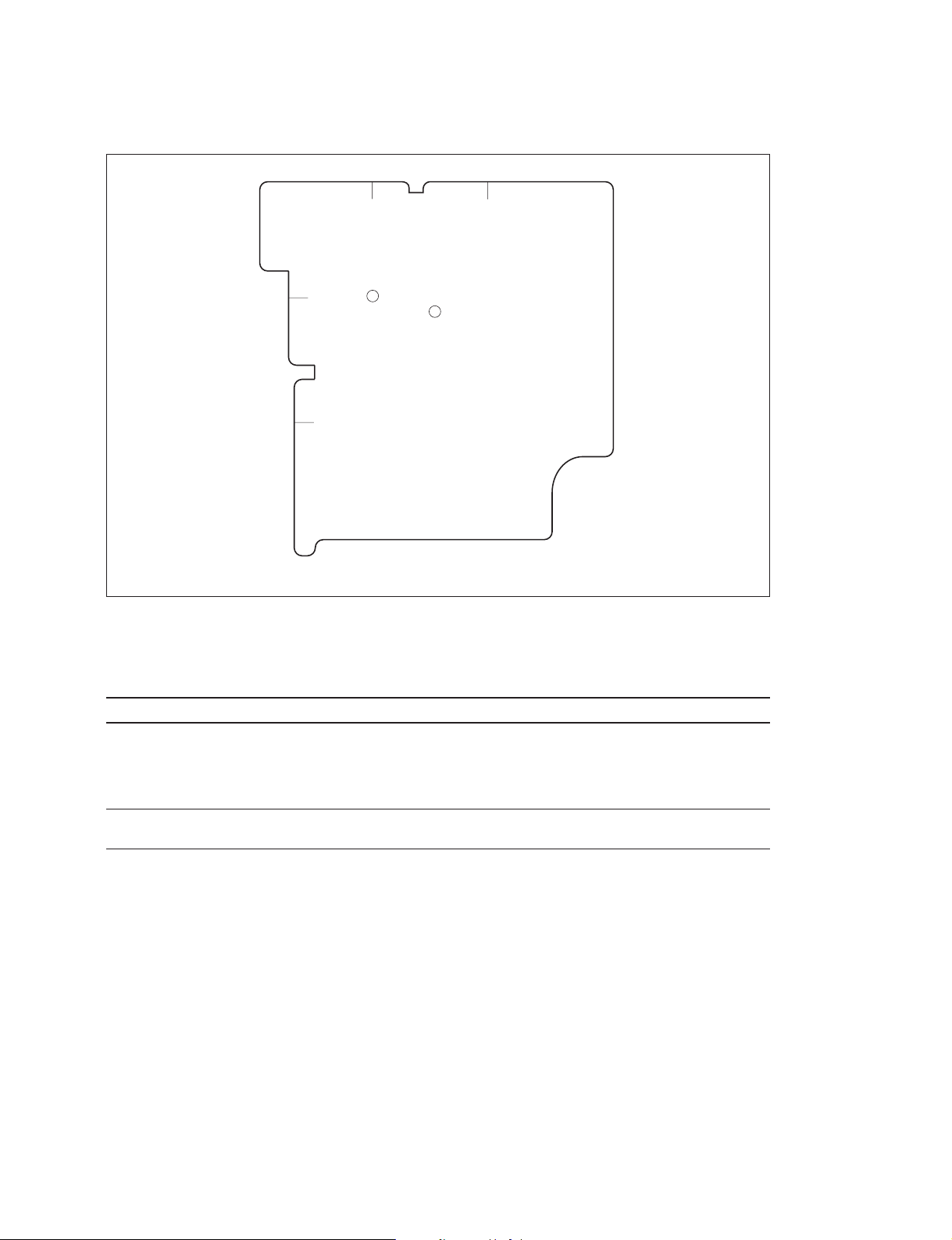
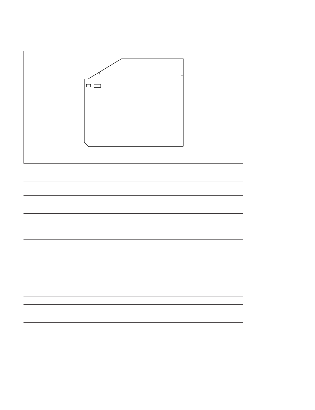
1-3. Main Part Locations and Circuit Functions
1-3. Main Part Locations and Circuit Functions
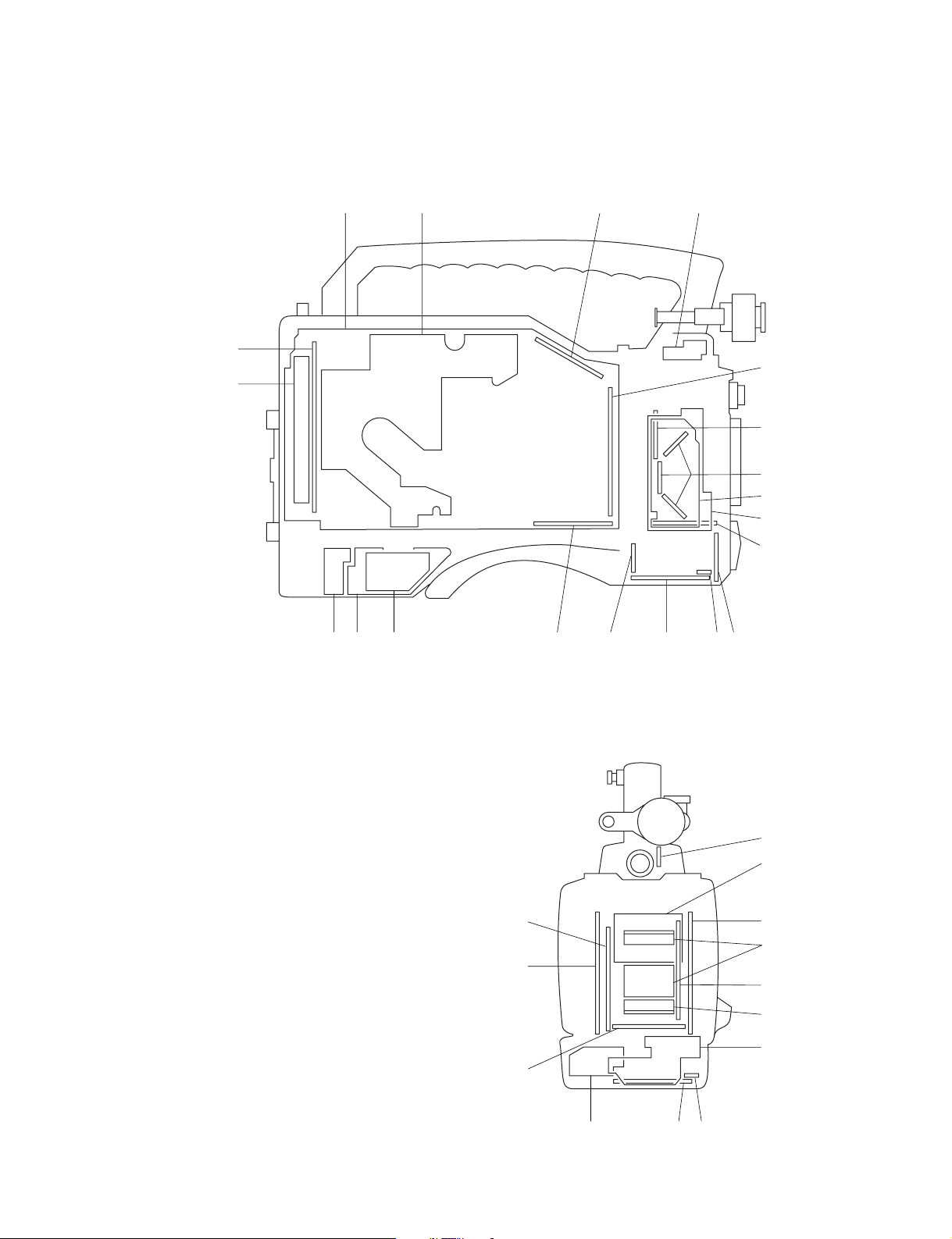
1-3-1. Printed Circuit Board Locations
AD-155 ........ 3
AXM-21 ......!]
BC-31*1........#;
BC-32*2........#;
BF-74 ........... 5
BI-96............#[
CI-20............!-
CI-21............0
CN-1183 ...... $,
CN-1573*1....!.
CNB-11........ !'
CP-329 ......... @[
CTL-10 ........ @.
CUE-2..........$-
DC-101 ........ !=
DC-106 ........ ![
DCP-17 ........ @=
DIF-75 ......... 9 (BKDW-702)
DR-387 ........ $'
DVP-14........@]
DVP-17........@\
ES-23 ...........@/
FM-65*3.......5 (BKDW-704)
HN-260 ........ #-
HP-93........... !;
IF-716 .......... #.
IO-178.......... $[
KY-293 ........ 4
LP-109 .........6
LP-111 .........!\
MA-94 ......... $/
MB-810........ !,
MB-811........ @;
MY-93 ......... @' (BKDW-703)
PA-228......... #]
PS-533 ......... 7
RC-69*2........!.
RC-75*2........!.
RE-160......... $;
RE-161......... $\
RM-180........ $]
SE-275 .........@,
SV-210......... 8
@[
SW-971........#'
SW-972........2
SW-973........#/
SW-983........#,
TC-101......... @-
TG-206*1......#=
TG-207*2......#=
VA-191 ........ #\
VR-248 ........ 1
VSE-32 ........ $=
3412
@= @-
< Inside Panel View >
5
!.
@-
5
!,
@/ !' !; !\!\!]
4
@=
!.
6
6
7
8
9
0
!-
!=
![
7
@]
@\
@;
@'
!=
!'
*1 : For DVW-707/707P only
*2 : For DVW-790WS/790WSP/709WS/709WSP only
*3 : Dedicated optional board for DVW-790WS/790WSP/709WS/709WSP
1-2
!;
![
< Rear Panel View >
!]
DVW-790WS/709WS/707
DVW-790WSP/709WSP/707P P1
#;
#;
#]
#\
#-
#/
#[
$,
#[
#'
$/ #. #,
#=
#/
$'
@.@; @,
$-
$/ #. #,
#'
$] $[ $=
$;
$\
#=
#[
#]
#\
1-3. Main Part Locations and Circuit Functions
Inside Panel View : 1 through @[
(Some boards are also indicated in
the Rear Panel View.)
Rear Panel View : @] through @'
Outside Panel View :@, through $;
(Some boards are also indicated in
the Front Panel View.)
Front Panel View : $' and $,
< Outside Panel View >
DVW-790WS/709WS/707
DVW-790WSP/709WSP/707P P1
< Front Panel View >
1-3

1-3. Main Part Locations and Circuit Functions
1-3-2. Circuit Functions
System Board Function
CCD BLOCK BI-96 CCD Imager (R, G, B)
CN-1183 Connector for BI-96
DR-387 CCD Driver
PA-228 Pre-amp (Sample & Hold)
TG-206*1/TG-207
VA-191 Video Amp
CAMERA/VIDEO AD-155 A/D Converter
BF-74 Connector for DCP-17
CN-1573
RC-69*2+RC-75
DCP-17 Camera Processor
DVP-14 Digital Bit Reduction Decoder, Digital Encoder, Digital Decoder,
DVP-17 RF, Digital Audio Processor, System Controller for VTR Block
ES-23 Composite Encoder
TC-101 Analog Audio Processor, Time Code Generator
HEAD/SERVO CTL-10 CTL/Erase Head Amp
CUE-2 CUE Head Amp
HN-260 Harness, Head Amp (REC Head PB)
SV-210 Servo Controller
MICROPHONE IF-716 Lens Control, Mic Amp
MA-94 Camera Mic Pre-amp
SW-971 Mic Level, Auto White/Black SW, VTR Start/Stop SW,
POWER SUPPLY DC-101 Battery DC Filter
PS-533 Power Supply (Light)
RE-160 Regulator
RE-161 Regulator, Switching Control
CONNECTOR BOX AXM-21 Connector (AUDIO IN/OUT), Audio Pre-amp
CNB-11 Circuit Breaker
DC-106 External DC Filter
IO-178 Connector (GEN LOCK IN, TEST OUT, TC IN, TC OUT)
LP-111 Rear Tally
RM-180 Connector (RM)
VSE-32 GENLOCK IN Filter
*1 : For DVW-707/707P only
*2 : For DVW-790WS/790WSP/709WS/709WSP only
*2
*1
*2
Timing Generator
Connector for DCP-17
Rate (16:9 to 4:3) Converter
Timing Clock Generator
Shutter On/Off Select SW
1-4
DVW-790WS/709WS/707
DVW-790WSP/709WSP/707P P1

System Board Function
OTHERS CI-20 Connector (40-pin)
CI-21 40-pin Adaptor Interface
CP-329 Switch Panel
HP-93 Earphone
KY-293 Function Key
LP-109 Back Tally, Back Tally Switch
MB-810 Motherboard
MB-811 Motherboard
SE-275 Sensor
SW-972 Turbo Gain Switch
SW-973 Menu and Light Auto/Manual Switch
SW-983 Rotary Encoder Switch
VR-248 Memory Card, Audio Select Switch, Alarm Level, Monitor Level
OPTION FM-65*3 (BKDW-704) Image Inverter Board
DIF-75 (BKDW-702) SDI Output Board
MY-93 (BKDW-703) Picture Cache Board
*3 : Dedicated optional board for DVW-790WS/790WSP/709WS/709WSP.
1-3. Main Part Locations and Circuit Functions
DVW-790WS/709WS/707
DVW-790WSP/709WSP/707P P1
1-5

1-3. Main Part Locations and Circuit Functions
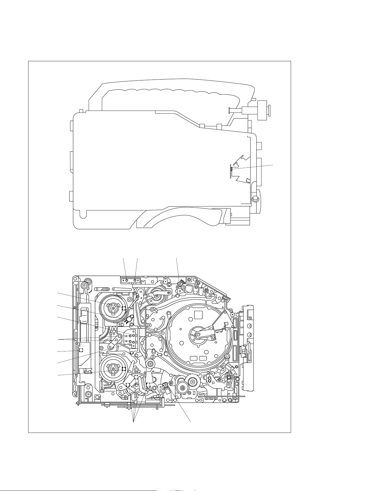
1-3-3. Mechanical Part Locations
2
1
Mechanical Deck
#=
#-
#/
@.
@,
34567890!-
!=
![
!]
!\
1-6
@' @; @\ @] @[ @= @- @/ !. !, !' !;
DVW-790WS/709WS/707
DVW-790WSP/709WSP/707P P1

1 CCD block
2 DC fan motor
3 Tension regulator arm
4 S1 tape guide (on S slider)
5 S2 tape guide (on S slider)
6 Tension regulator guide (S4 tape guide)
7 S5 tape guide
8 S3 tape guide
9 Full erase head
0 Tape cleaner
!- CTL head
!= Brush
![ Slip ring
!] Video head cleaner
!\ Upper drum
!; Lower drum
!' CUE head cleaner
!, CUE/TC head
!. Manual eject knob
@/ Threading motor
@- Capstan motor
@= T3 tape guide
@[ T drawer guide
@] Pinch roller
@\ T2 tape guide (on T slider)
@; T1 tape guide (on T slider)
@' T soft brake
@, T reel table
@. Timing belt
#/ Gear
#- S reel table
#= Brake band
1-3. Main Part Locations and Circuit Functions
DVW-790WS/709WS/707
DVW-790WSP/709WSP/707P P1
1-7
1-3. Main Part Locations and Circuit Functions
1-3-4. Sensor Locations and Functions
1
Mechanical Deck
!=
!-
0
(Spare)
8
9
7
6
32
4
5
1-8
DVW-790WS/709WS/707
DVW-790WSP/709WSP/707P P1

1-3. Main Part Locations and Circuit Functions
1 Temperature Detection Sensor
Detects the temperature, to perform the black correction.
2 Cassette-in Sensor
Detects the existence of a cassette.
3 REC INHIBIT Sensor
Detects the REC inhibiting plug of the cassette tape.
4 Tape End Sensor
Detects the end of the tape that runs in the forward direction.
5 Tape Top Sensor
Detects the end of the tape that runs in the reverse direction.
6 Function Cam Sensor
Detects the rotation position of a cam.
7 Take-up Reel Table Rotating Sensor
Detects the rotation of the take-up reel table. The FG output signal of this sensor is input to a servo
circuit so as to calculate the winding diameter of the tape.
8 Cassette Lock Sensor (Switch)
Detects that the cassette compartment was locked.
9 Tape Thickness Sensor
Using a tub on the back side of the cassette tape, this sensor detects the thickness of the tape wound
on a cassette tape that is being inserted into the unit.
0 Reel Hub Diameter Sensor
The reel hub diameter of a cassette tape varies depending on the length of the tape wound on the
cassette tape. The reel hub diameter sensor detects the reel hub diameter by the tab on the back side
of the cassette tape. The output signal of this sensor is input to a servo circuit so as to calculate the
winding diameter of the tape.
!- Condensation Sensor
Detects whether the dew condensation occurs in the unit.
!= Supply Reel Table Rotating Sensor
Detects the rotation of the supply reel table. The FG output signal of this sensor is input to a servo
circuit so as to calculate the winding diameter of the tape.
DVW-790WS/709WS/707
DVW-790WSP/709WSP/707P P1
1-9

1-4. Matching Connectors
1-4. Matching Connectors
When external cables are connected to the connector during maintenance, the hardware listed below (or
the equivalents) must be used:
Panel Indication Matching Connector/Cable
Name Part No.
AUDIO IN CH-1/CH-2 XLR 3-pin, male 1-508-084-00
AUDIO OUT Audio cable SONY CCXA-53 or equivalent
GENLOCK IN BNC 1-569-370-12
TC IN
TC OUT
TEST OUT
VIDEO OUT
DC IN XLR 4-pin, female 1-508-362-00
DC OUT 12 V DIN 4-pin, male 1-566-425-11
MIC IN +48 V XLR 3-pin, male 1-508-084-00
REMOTE 6-pin, male 1-560-078-00
EARPHONE Mini jack Available separately
LIGHT Power tap [OE] ANTONBAUER 33710 or equivalent
(XLR 5-pin _ XLR 3-pin, 2 m)
1-10
DVW-790WS/709WS/707
DVW-790WSP/709WSP/707P P1
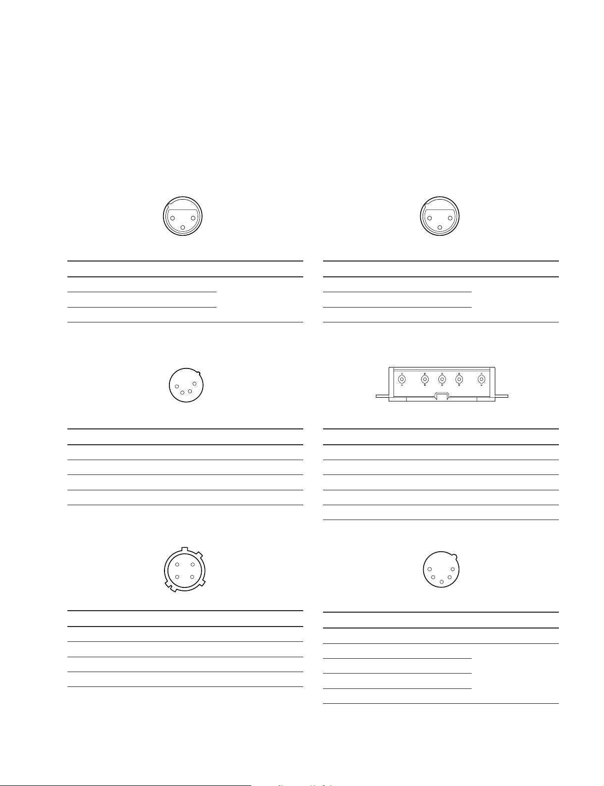
1-5. Signal Inputs and Outputs
12345
1-5. Signal Inputs and Outputs
Inputs
GENLOCK IN 1.0 V p-p, 75 Z
TC IN 0.5 V to 18 V p-p, 10 kZ
MIC IN : XLR 3-pin, female
2
1
3
<External View>
Pin No. Signal Specification
1 MIC IN (G) _60 dBu High
2 MIC IN (X)
impedance balance
3 MIC IN (Y)
(0 dBu=0.775 Vrms)
DC IN : XLR 4-pin, male
4
1
3
2
Outputs
TEST OUT 1.0 V p-p, 75 Z, unbalanced
TC OUT 1.0 V p-p, 75 Z
VIDEO OUT 1.0 V p-p, 75 Z, unbalanced
EARPHONE
_∞ to _18 dBu, adjustable, 8 Z
AUDIO IN CH1/CH2 : XLR 3-pin, female
2
1
3
<External View>
Pin No. Signal Specification
1 LINE/MIC IN (G)
2 LINE/MIC IN (X)
+4 dBu/_60 dBu High
impedance balance
3 LINE/MIC IN (Y)
(0 dBu=0.775 Vrms)
BATT IN : 5-pin, male
<External View>
Pin No. Signal Specification
1 GND
2 _
3 _
4 EXT DC IN DC 11 to 17 V
DC OUT 12V : DIN 4-pin, female
4
1
2
3
<External View>
Pin No. Signal Specification
1 UNREG GND
2 _
3 _
4 UNREG +12 V OUT 0.1 A MAX
<External View>
Pin No. Signal Specifications
1 BATT IN (_)
2 BATT IND IN
3 BATT REM IN
4 LIGHT CONT OUT
5 BATT IN (+) DC11 to 17 V
AUDIO OUT : XLR 5-pin, male
1
5
2
4
3
<External View>
Pin No. Signal Specifications
1 GND
2 CH1 (X) OUT 0 dBm
3 CH1 (Y) OUT
4 CH2 (X) OUT
5 CH2 (Y) OUT
(Terminated in 600 Z)
DVW-790WS/709WS/707
DVW-790WSP/709WSP/707P P1
1-11
1-5. Signal Inputs and Outputs
VF : 20-pin, female
3
1
4
9
13
18
<External View>
Pin No. Signal Specifications
1 VTR SAVE OUT L : Light on,
2 ABNORMAL OUT L : Light on,
3 16:9/4:3 OUT H : NORMAL (4:3)
4 REC (L) OUT H : Light on,
5 COLOR VF DET IN H : Color, L : B/W
6 CCIR/EIA OUT H : CCIR, L : EIA
7 DISPLAY ON IN OPEN : ON, L : OFF
8 G TALLY OUT H : Light on,
9 _
10 Y (X) OUT 1 Vp-p, VF : Zi=1 kZ
11 ZEBRA ON IN H : OFF, L : ON
12 VIDEO (X) OUT 1 Vp-p, VF : Zi=1 kZ
13 AUDIO CTL IN
14 B-Y (Y) OUT 700 mVp-p,
15 R-Y (X) OUT 700 mVp-p,
16 BATT IND OUT H : Light on,
17 REC/TALLY OUT H : Light on,
18 +9.3 OUT REG +9.3 V
19 GND
20 UNREG OUT +11 V to 17 V
8
12
17
20
OPEN : Light off
OPEN : Light off
L : WIDE (16:9)
L : Light off
L : Light off
VF : Zi=1 kZ,
75% color-bars
VF : Zi=1 kZ,
75% color-bars
L : Light off
L : Light off
REMOTE : 8-pin, female
1
7
2
8
6
3
4
5
<External View>
Pin No. Signal Specifications
1 RM TX (+) OUT
2 RM TX (_) OUT
3 RM RX (+) IN
4 RM RX (_) IN
5 UNREG GND
6 UNREG +12 V OUT +11 V to 17 V
7 RM TEST (G) OUT
8 RM TEST (X) OUT 1 Vp-p, Zo=75 Z
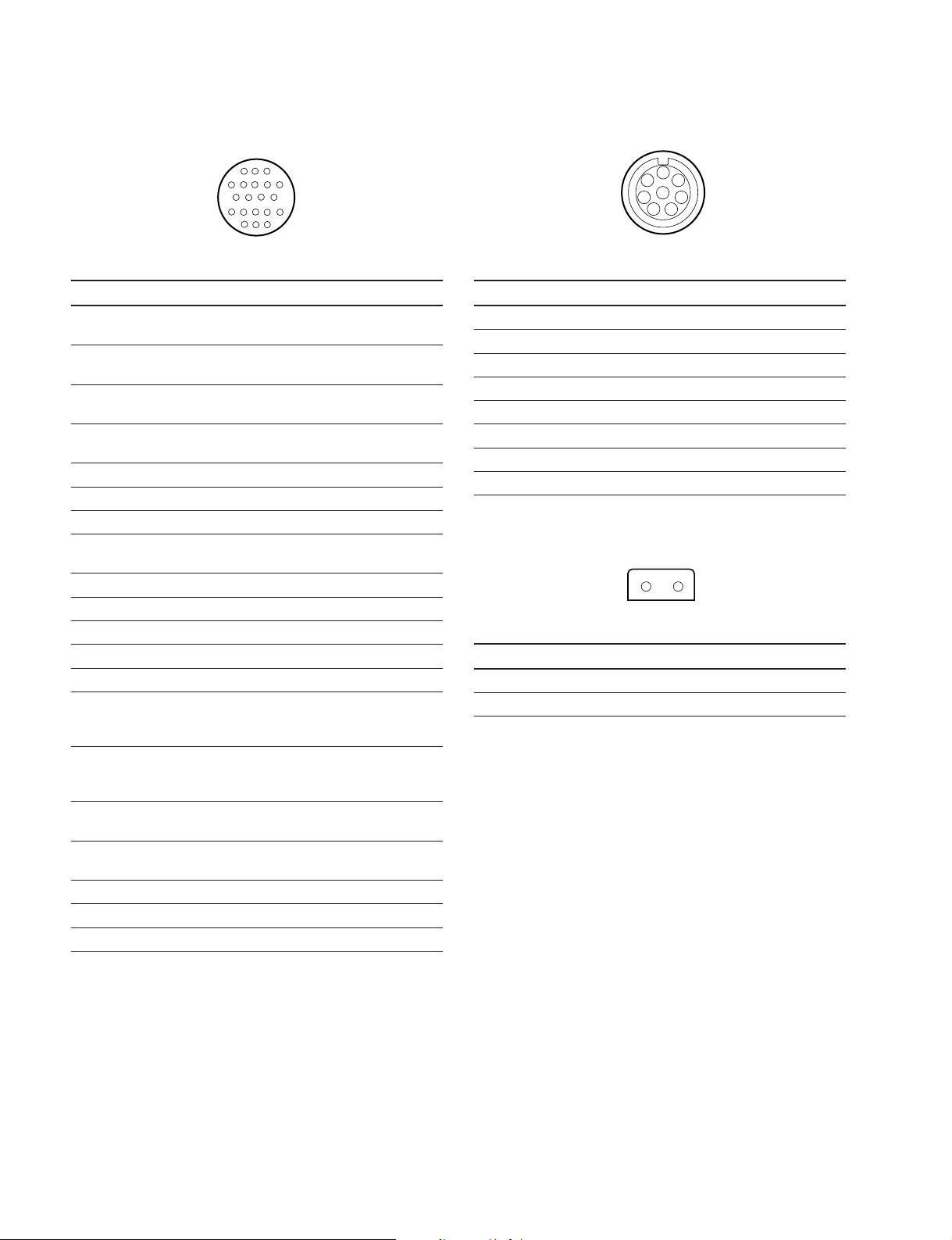
LIGHT : 2-pin, female
2
<External View>
Pin No. Signal Specifications
1 LIGHT +12 V OUT 50 W MAX
2 GND
1
1-12
DVW-790WS/709WS/707
DVW-790WSP/709WSP/707P P1

LENS: 12-pin, female
9
1
2
3
4
<External View>
Pin No. Signal Specifications
1 RET(SW) IN L : ON, OPEN : OFF
2 VTR TRIG IN L : ON
3 LENS GND
4 AUTO +5 V IN AUTO : +5 V
5 IRIS CONT OUT +3.4 V (F16) to
6 UNREG +12 V OUT +11 V to 17 V
7 IRIS POSITION IN +3.4 V (F16) to
8 REMOTE/LOCAL IN
9 EXTENDER IN EX 2 ON : 0 V
10 ZOOM POSITION IN WIDE : 2 V
11 N.C No connection
12 N.C No connection
8
10
12
7
11
6
5
MANU : 0 V or OPEN
+6.2 V (F2.8)
+6.2 V (F2.8)
EX 0.8 ON : +1.8 V
OFF : +4.8 V
TELE : 7 V
1-5. Signal Inputs and Outputs
DVW-790WS/709WS/707
DVW-790WSP/709WSP/707P P1
1-13

1-6. Removing/Reinstalling Outside Panel
1-6.
Removing/Reinstalling Outside Panel
Removing
n
Be sure to turn off the power, and then disconnect the
power cord and/or battery before performing the following
steps. If not, damage to internal circuit may result.
1. Fully loosen the left screw (with drop-safe) of the front
lid.
2. Fully loosen the four screws of the outside panel to
remove the panel.
Front lid
Outside panel
Reinstalling
1. Sliding the hook of the outside panel onto the guide
shaft of the cassette compartment, install the outside
panel.
2. Fasten the screws of the outside panel.
n
Tightening Torque : 140 x 10
_2
N.m {14.3 kgf.cm}
Screws
(with drop-safe)
Screws (with drop-safe)
Screws
(with drop-safe)
Guide shaft of the
cassette compartment
Screws (with drop-safe)
Hook of the outside panel
1-14
DVW-790WS/709WS/707
DVW-790WSP/709WSP/707P P1
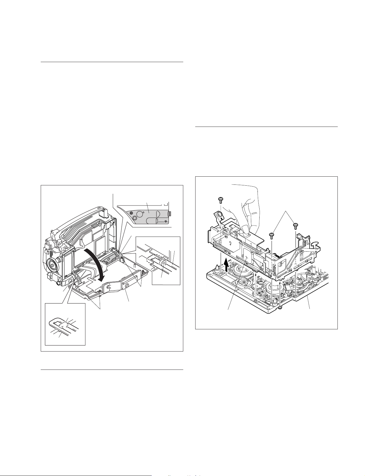
1-8. Removing/Reinstalling Cassette Compartment
1-7. Opening/Closing Inside Panel
1-7. Opening/Closing Inside Panel
Opening
m
. To avoid damage to internal circuit, be sure to turn off
the power, and then disconnect the power cord and/or
battery before following the steps below.
. To protect the connector box from a damage by rubbing
against the hinge, slip in a sheet of paper between the
box and hinge when opening the inside panel.
1. Fully loosen the four screws (with drop-safe), and then
open the inside panel in the direction of the arrow.
n
Be careful not to bend the flexible wires connected to
the TC-101 board intentionally.
Cover here
(with a sheet of paper).
1-8. Removing/Reinstalling Cassette
Compartment
m
. To avoid damage to internal circuit, be sure to turn off
the power, and then disconnect the power cord and/or
battery before following the steps below.
. The cassette compartment is removable in either of up or
down position.
Removing
1. Remove the outside panel. (Refer to Section 1-6.)
2. Remove the three screws of the cassette compartment.
3. Grasp the cassette compartment by the portion shown
in the figure and lift it out.
Screws
(
M 1.4x2.5
)
Screws
(
M 1.4x2.5
)
Hinge (R)
Closing (step 1)
Hinge (R)
Hook
Hinge (F)
Closing (step 1)
Hook
Hinge (F)
Screws
(with drop-safe)
Screws
(with drop-safe)
Inside panel
Closing
1. Ensure that the hinges (F) and (R) are properly hitched
on the hooks of chassis.
2. Close the inside panel, and then fasten the four screws
(with drop-safe) to install the panel.
m
. Tightening Torque : 140 x 10
_2
N.m {14.3 kgf.cm}
. Be careful not to pinch harnesses between the inside
panel and chassis.
Cassette compartment
Mechanical deck
assembly
DVW-790WS/709WS/707
DVW-790WSP/709WSP/707P P1
1-15
1-8. Removing/Reinstalling Cassette Compartment
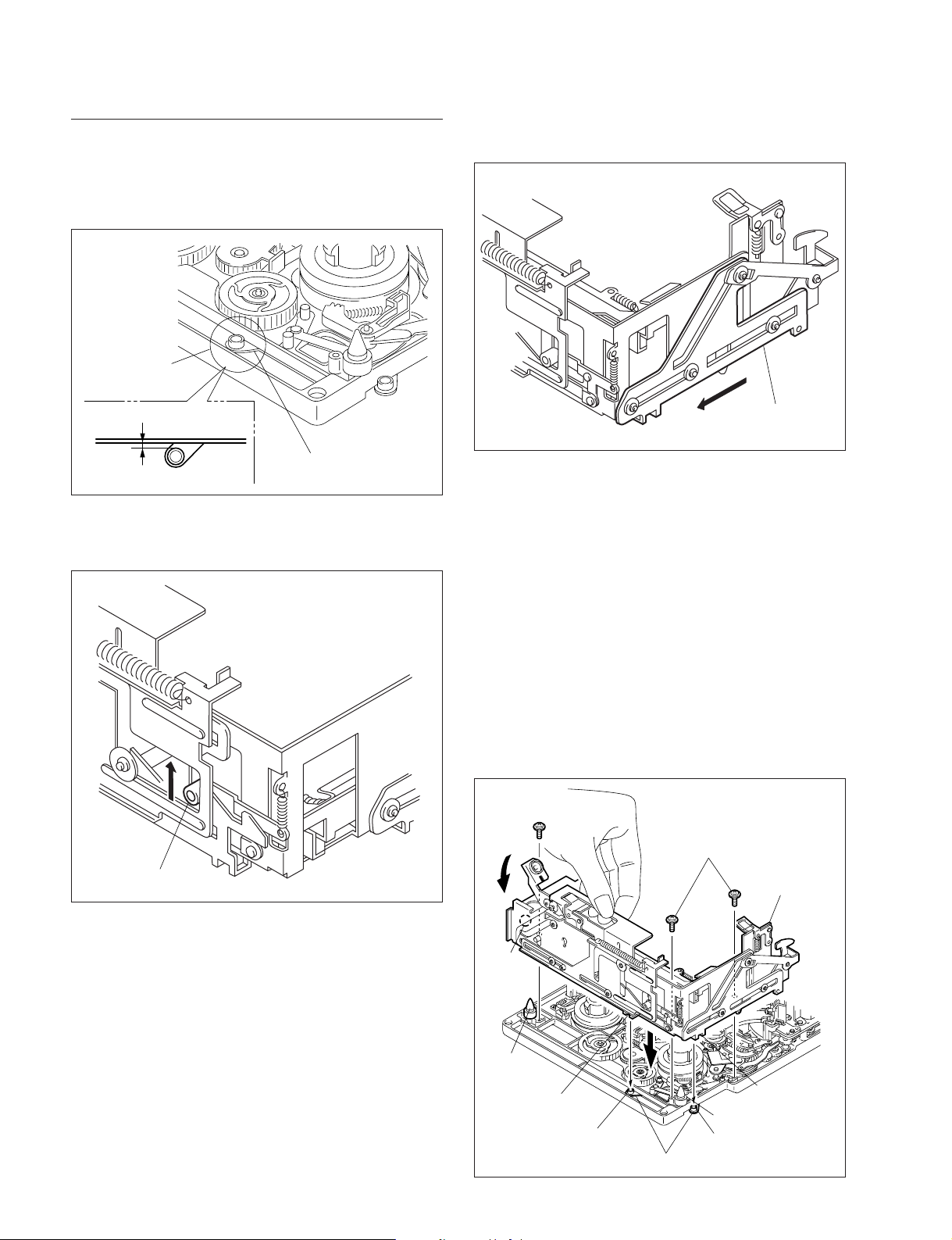
Reinstalling
1. To create a clearance of 0.5 mm between the white
roller of joint arm and the end face of mechanical
deck, adjust the position of the joint arm.
Roller (white)
End face of mechanical deck
0.5 mm
Outside surface of roller
Joint arm
2. Slide the white lock-roller of cassette compartment in
an upward direction.
3. Slide the cam plate (A) on the right of the cassette
compartment all the way of the arrow until it stops.
Cam plate (A)
4. Grasp the cassette compartment by the portion shown
in the figure and set it on the stage to insert the two
cassette-guide-pins onto the round hole of the stage.
Check that the other white-roller of joint arm positioned in step 1 is put in the notch of the cam plate (A)
on the right side.
5. Push down the lever of the cassette compartment and
check to see that the stage smoothly moves up and
down. If not moved smoothly, recheck the steps 1
through 4.
6. Fasten the cassette compartment using the three
screws.
n
Tightening Torque : 9 x 10
_2
N.m {0.9 kgf.cm}
Lock-roller (white)
1-16
Screw
(
M 1.4x2.5
Lever
Round
hole of
the stage
Cassetteguide-pin
Notch
White-roller in step 1
)
Screws
Joint arm
(
M 1.4x2.5
)
Stage
Notch of the
cam plate (A)
Cassette-guide-pin
Other white-roller
DVW-790WS/709WS/707
DVW-790WSP/709WSP/707P P1
1-9. Removing/Reinstalling Plug-in Boards
1-9.
Removing/Reinstalling Plug-in Boards
Be careful not to damage the board and to position and
orient the board correctly when removing/reinstalling the
plug-in boards.
1-9-1. DCP/DVP Board Assembly
m
. When replacing the board, set the switches on the new
board.
DCP-17 board : Refer to Section 1-10-3.
DVP-17 board : Refer to Section 1-10-4.
. After replacing the board, see the Maintenance Manual
Part 2 Vol.1 and perform adjustments as follows :
DCP-17 board : Sec. 7. Camera System Electrical
Alignment
DVP-17 board : Sec. 6-5. Video System Adjustment
(Automatic Equalizer Adjustment and
REC Current Adjustment)
Removing
Reinstalling
1. Stay opens the levers of the board in advance.
2. Insert the DCP or DVP board assembly along the
board guide rails.
3. After the shafts of levers get into the chassis, close the
levers and press in the board to firmly connect it to the
connector of the MB-810 board.
4. Reconnect the harnesses to the connectors CN12 and
CN13 on the DCP board assembly.
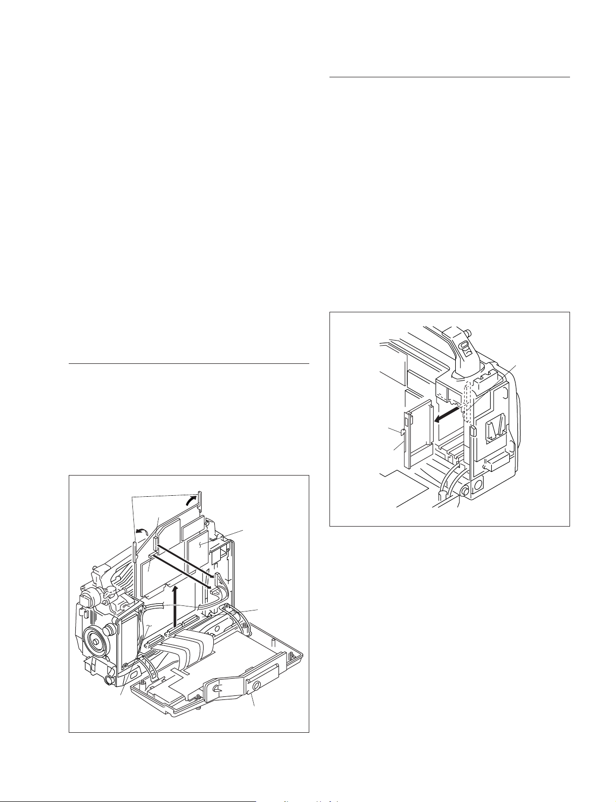
1-9-2. SV-210 Board
1. Open the inside panel. (Refer to Section 1-7.)
2. Grasp the board by the pull ring and pull it out to
disconnect the SV-210 board from the connectors of
MB-811 board.
MB-811 board
1. Open the inside panel. (Refer to Section 1-7.)
2. Remove the harnesses from the connectors CN12 and
CN13 on the DCP board assembly.
3. Open the levers to disconnect the DCP or DVP board
assembly from the connectors on the MB-810 board.
4. Lift the DCP or DVP board assembly out.
Levers
CN12
DCP board
assembly
CN13
MB-810
board
Pull ring
SV-210 board
DVP board
assembly
DVW-790WS/709WS/707
DVW-790WSP/709WSP/707P P1
Inside panel
1-17

1-10. Switch/Slit Land Settings and LED Functions on the Boards
1-10. Switch/Slit Land Settings and LED Functions on the Boards
As for the external-switch settings, see Section “2. Locations and Functions of the Parts and Controls” in
the Operation Manual.
n
Never change the settings of switches specified “Factory use”.
1-10-1. AXM-21 Board
SL301
SL300
AXM-21 B side
Slit Lands
Ref. No. Name Description Factory setting
SL300 AUDIO OUT Select OPEN : Output from the XLR 5-pin connector OPEN
SHORT : Output from the XLR 3-pin connector
SL301 AUDIO OUT Select OPEN : Output from the XLR 3-pin connector
SHORT : Output from the XLR 5-pin connector
*1 : If the AUDIO OUT connector (XLR 5-pin) is converted to XLR 3-pin connectors, set the slit lands as specified above. (The XLR 3-pin
connectors are not supplied. Ready them separately.)
*2 : This slit land is short-circuited by the traces on the board. Therefore, the traces must be cut using a knife when the setting is
changed.
*1
*1
SHORT
*2
1-18
DVW-790WS/709WS/707
DVW-790WSP/709WSP/707P P1
1-10-2. CNB-11 Board
1-10. Switch/Slit Land Settings and LED Functions on the Boards
A
1
SL1
2
3
BC
SL401
CNB-11 A side
Slit Lands
n
Set SL1 according to the destination when replacing the board.
Ref. No. Description Factory setting
SL1 Selects how the power is derived when the battery and external power supply OPEN
SL401 Destination Select OPEN : For the area except Japan
are used simultaneously :
OPEN : Always derived power from the external power supply.
SHORT : Automatically derived power from either of the battery or external
power supply which is in higher input-voltage.
OPEN (for except Japan)
SHORT : For Japan SHORT (for Japan)
DVW-790WS/709WS/707
DVW-790WSP/709WSP/707P P1
1-19
1-10. Switch/Slit Land Settings and LED Functions on the Boards
1-10-3. DCP-17 Board
S1
EDC
B
A
S4
DCP-17 B side
F
1
2
3
4
5
6
Switches
Ref. No. Name Description Factory
setting
S1 ENG Disable Select Switching ON/OFF of engineer mode OFF
S4-1 SVC Enable Select Switching ON/OFF of service mode OFF
S4-2 _ Factory use OFF
S4-3 VF CAM Select Output signal selection when the OUTPUT/DCC switch OFF
S4-4 CA Mode Function selection of the VTR START button OFF
S4-5 to 7 _ Not used OFF
S4-8 Data reset ON : Resets the setting menu when the power is OFF
ON : Disables
OFF : Enables
ON : Enables
OFF : Disables
is set to BARS
ON : Outputs the camera signal on the viewfinder.
OFF : Outputs the color bars signal on the viewfinder.
ON : Uses the VTR START button as the RET 2 button.
(The VTR SAVE/STBY switch is used as the
INCOM TALK ON button.)
OFF : Uses the VTR START button as the INCOM TALK
ON button.
turned on.
OFF : Not resets. (under normal use)
1-20
DVW-790WS/709WS/707
DVW-790WSP/709WSP/707P P1
 Loading...