

Sony DVW-709WS, DVW-790WS, DVW-707, DVW-709SP, DVW-790WSP User Manual
...
DIGITAL BETACAM CAMCORDER
DVW-707/707P
DVW-709WS/709WSP
DVW-790WS/790WSP
OPERATION MANUAL
1st Edition (Revised 1)
[English]

WARNING
To prevent fire or shock hazard, do not
expose the unit to rain or moisture.
To avoid electrical shock, do not open
the cabinet. Refer servicing to qualified
personnel only.
For the customers in the USA
This equipment has been tested and found to comply with
the limits for a Class B digital device, pursuant to Part 15
of th e FCC Rules. These limits are designed to provide
reasonable protection against harmful interference in a
residential installation. This equipment generates, uses,
and can radiate radio frequency energy and, if not installed
and used in accordance with the instructions, may cause
harmful interference to radio communications. However,
there is no guarantee that interference will not occur in a
particular installation. If this equipment does cause
harmful interference to radio or television reception, which
can be determined by turning the equipment off and on,
the user is encouraged to try to correct the interference by
one or more of the following measures:
— Reorient or relocate the receiving antenna.
— Increase the separation between the equipment and
receiver.
— Connect the equipment into an outlet on a circuit
different from that to which the receiver is connected.
— Consult the dealer or an experienced radio/TV
technician for help.

You are cautioned that any changes or modifications not
expressly approved in this manual could void your
authority to operate this equipment.
The shielded interface cable recommended in this manual
must be used with this equipment in order to comply with
the limits for a digital device pursuant to Subpart B of Part
15 of FCC Rules.
For the customers in the USA and Canada
RECYCLING NICKEL-CADMIUM BATTERIES
Nickel-Cadmium batteries are recyclable.
You can help preserve our environment
by returning your unwanted batteries to
your nearest point for collection,
recycling or proper disposal.
Note: In some areas the disposal of nickel-cadmium
batteries in household or business trash may be
prohibited.
RBRC(Rechargeable Battery Recycling Corporation)
advises you about spent battery collection by the following
phone number.
Call toll free number: 1-800-822-8837 (United States
and Canada only)
Caution: Do not handle damaged or leaking nickel
cadmium batteries.

For the customers in Europe
This product with the CE marking complies with the EMC
Directive(89/336/EEC) issued by the Commission of the
European Community.
Compliance with this directive implies conformity to the
following European standards:
• EN55103-1: Electromagnetic Interference(Emission)
• EN55103-2: Electromagnetic Susceptibility(Immunity)
This product is intended for use in the following
Electromagnetic Environment(s):
E1 (residential), E2 (commercial and light industrial), E3
(urban outdoors) and E4 (controlled EMC environment, ex.
TV studio)

Table of Contents
Chapter 1 Overview
1-1 Features .....................................................................................1-1
1-1-1 Camera Features .............................................................. 1-2
1-1-2 VTR Features ..................................................................1-4
1-2 Example of System Configuration ..........................................1-6
1-3 Precautions ................................................................................ 1-8
Chapter 2 Locations and Functions of Parts and
Controls
2-1 Power Supply ............................................................................2-1
2-2 Accessory Attachments ............................................................2-3
2-3 Audio Functions........................................................................2-5
2-4 Shooting and Recording/Playback Functions ......................2-14
2-5 Setup Menu Operating Section .............................................2-27
2-6 Time Code System ..................................................................2-29
2-7 Warnings and Indications......................................................2-35
2-8 Warnings and Indications on the Display Panel..................2-38
Chapter 3 Recording and Playback
3-1 About Cassettes.........................................................................3-1
3-1-1 Loading and Unloading a Cassette..................................3-1
3-1-2 Preventing Accidental Erasure ........................................3-4
3-2 Recording ..................................................................................3-5
3-2-1 Basic Procedure...............................................................3-5
3-2-2 Continuous Recording.....................................................3-9
3-2-3 Starting a Shoot with a Few Seconds of Pre-Stored Picture
Data (Loop Rec Function) (When Using a BKDW-703
Extension Board)...........................................................3-12
3-2-4 Reversing the picture orientation (vertically and
horizontally) (Using the BKDW-704 Extension Board)
(DVW-709WS/709WSP/790WS/790WSP only) ......... 3-18
3-3 Checking the Recording — Playback ...................................3-19
Table of Contents 1

3-3-1 Checking the Last Two Seconds of the Recording
— Recording Review .................................................... 3-19
3-3-2 Checking the Recording on the Color Video Monitor
— Playback in Color ..................................................... 3-20
Chapter 4 Adjustments and Settings for
Recording
4-1 Adjusting the Black Balance and the White Balance............4-1
4-1-1 Adjusting the Black Balance ...........................................4-2
4-1-2 Adjusting the White Balance .......................................... 4-5
4-2 Setting the Electronic Shutter ...............................................4-13
4-2-1 Shutter Modes ...............................................................4-13
4-2-2 Selecting the Shutter Mode and Speed..........................4-15
4-3 Changing the Reference Value for Automatic Iris Adjustment
..................................................................................................4-21
4-4 Adjusting the Audio Level .....................................................4-24
4-5 Setting the Time Data.............................................................4-27
4-5-1 Setting the User Bits......................................................4-27
4-5-2 Setting the Time Code...................................................4-29
4-5-3 Saving the Real Time in the Time Code .......................4-31
4-5-4 Synchronizing the Time Code.......................................4-32
4-5-5 Setting Cassette Numbers and Shot Numbers...............4-37
4-6 Setup Menu Display on the Viewfinder Screen ...................4-39
4-6-1 Setup Menu Configuration ............................................4-39
4-6-2 Basic Use of the Setup Menu ........................................4-43
4-7 Indicators in the Viewfinder..................................................4-48
4-7-1 Layout of Indicators in the Viewfinder .........................4-48
4-7-2 Setting the Indicator.................................................4-50
4-8 Status Display on the Viewfinder Screen .............................4-53
4-8-1 Layout of the Status Display on the Viewfinder Screen4-54
4-8-2 Selecting the Display Items...........................................4-58
4-8-3 Display Mode and Setting Change and Adjustment Progress
Messages .......................................................................4-61
Table of Contents2

4-8-4 Setting the Marker Display ........................................... 4-64
4-8-5 Recording Superimposed Shot Data in Color Bars ....... 4-66
4-8-6 Setting the Shot ID ........................................................4-69
4-8-7 Displaying Time Code and Other Information ............. 4-73
4-9 Adjustments and Settings From the Setup Menu................4-76
4-9-1 Setting the GAIN Selector Values ................................ 4-77
4-9-2 Selecting the Functions .................................................4-79
4-9-3 Selecting the Test Output ..............................................4-83
4-9-4 Selecting the Aspect Ratio (DVW-709WS/709WSP/
790WS/790WSP Only) .................................................4-85
4-9-5 Setting the color temperature manually ........................ 4-91
4-9-6 Specifying an offset for the auto white balance setting 4-93
4-9-7 Setting the CAMERAMAN menu ................................4-95
4-10 VTR Menu Display in the Display Panel..............................4-99
4-10-1Configuration and Functions of the VTR Menu ........... 4-99
4-10-2Using the VTR Menu ..................................................4-100
4-10-3Example Operations in the VTR Menu ....................... 4-106
4-11 Using the Setup Card ...........................................................4-113
4-11-1Handling the Setup Card .............................................4-113
4-11-2Using Data on the Setup Card .....................................4-115
Chapter 5 Setting Up the Camcorder
5-1 Power Supply ............................................................................5-1
5-1-1 Using a BP-L60A/L90A Battery Pack ............................5-1
5-1-2 Using an NP-1B Battery Pack ......................................... 5-4
5-1-3 Using a BP-90A Battery Pack ......................................... 5-5
5-1-4 Avoiding Breaks in Operation Due to Dead Batteries ....5-7
5-1-5 Using an AC Adaptor ...................................................... 5-8
5-1-6 Using the Anton Bauer Ultralight System ...................... 5-9
5-1-7 Using the Anton Bauer Intelligent Battery System ......... 5-9
5-2 Adjusting the Viewfinder.......................................................5-10
5-2-1 Adjusting the Viewfinder Position ................................ 5-10
5-2-2 Adjusting the Viewfinder Focus and Screen................. 5-12
Table of Contents 3

5-2-3 Detaching the Viewfinder .............................................5-13
5-2-4 Detaching the Eyepiece ................................................. 5-15
5-3 Mounting the Lens..................................................................5-17
5-4 Adjusting the Flange Focal Length.......................................5-18
5-5 Audio Input System ................................................................ 5-20
5-5-1 Using the Supplied Microphone....................................5-20
5-5-2 Using an External Microphone ..................................... 5-23
5-5-3 Attaching a UHF Portable Tuner (for a UHF Wireless
Microphone System) .....................................................5-28
5-5-4 Connecting Line Input Audio Equipment .....................5-33
5-6 Tripod Mounting ....................................................................5-34
5-7 Attaching the Shoulder Strap................................................5-36
5-8 Adjusting the Shoulder Pad Position .................................... 5-38
5-9 Putting On the Rain Cover ....................................................5-39
5-10 Connecting the Remote Control Unit ...................................5-42
Chapter 6 Maintenance
6-1 Testing the Camcorder Before Shooting ................................6-1
6-1-1 Preparations for Testing ..................................................6-1
6-1-2 Testing the Camera ......................................................... 6-3
6-1-3 Testing the VTR ..............................................................6-6
6-2 Maintenance ............................................................................ 6-10
6-2-1 Cleaning the Video Heads.............................................6-10
6-2-2 Cleaning the Viewfinder ...............................................6-10
6-3 Operation Warnings...............................................................6-12
Appendix
Specifications ..................................................................................... A-1
Video Camera Section ...............................................................A-2
VTR Section ..............................................................................A-5
Supplied Accessories ................................................................. A-8
Recommended Additional Equipment ...................................... A-8
Glossary ............................................................................................A-11
Index .................................................................................................... I-1
Table of Contents4

1-1 Features
The DVW-707/707P series 1) Digital Camcorder combines a color video
camera, which uses IT 2) type Power HADTM
Digital BETACAM series portable videocassette recorder. Its excellent
image quality, sensitivity, portability, and dust- and water-proof
construction make it ideal as a camcorder for ENG 5) and EFP 6) in the
same way the earlier DVW-700/700P. The introduction of a new method
of processing digital signals improves the image quality even further and
makes the camcorder far easier to use.
The DVW-790WS/790WSP employs FIT 7) type Power HAD sensor
CCDs featuring a lower smear level and the ability to switch between the
conventional aspect ratio of 4:3 and a wide screen aspect ratio of 16:9.
The DVW-709WS/709WSP is identical with the DVW-790WS/790WSP
except for its use of IT type Power HAD sensor CCDs and its lack of an
ECS (extended clear scan) mode.
....................................................................................................................................
1) The DVW-707/709WS/790WS is for the NTSC broadcast system. The DVW707P/709WSP/790WSP is for the PAL broadcast system. The descriptions given
in this manual apply to both models, any differences being clearly noted in the
text.
2) IT: Interline Transfer
3) Power HAD: Power Hole-Accumulated Diode
“Power HAD” is a registered trademark of Sony Corporation.
4) CCD: Charge-Coupled Device
5) ENG: Electronic News Gathering
6) EFP: Electronic Field Production
7) FIT: Frame Interline Transfer
3)
sensor CCDs 4), with a
Chapter 1 Overview 1-1
1
Overview

1-1-1 Camera Features
1
The features of the DVW-707/707P/709WS/709WSP/790WS/790WSP
series camera are described below.
• Power HAD sensor CCDs ensure high sensitivity and high image
quality.
• The 12 bit AD converter has improved picture quality, stability, and
reliability.
• A setup menu enables you to control features such as status displays,
messages, and markers; to select values or functions; and to operate a
setup card.
• The settable items in the CAMERAMAN menu allow you to create
your own custom menu.
• A setup card (not supplied) makes it easy to replicate the recorder setup
data appropriate to the shooting conditions, and ensures uniform
shooting 1).
• Use of a built-in sophisticated electronic shutter, which has selectable
modes, Clear ScanTM 2), Extended Clear Scan (for DVW-790WS/
790WSP only) and Super Enhanced Vertical Definition, ensures
shooting with little or no blurring.
• Selectable video gain ensures a noise-free image.
• A simple switch operation enables automatic adjustment of the black
set, black balance, and white balance. Memory functions make it easy
to replicate the settings appropriate for the lighting conditions.
• The ATW
3)
function automatically adjusts the white balance for the
varying lighting conditions during shooting.
....................................................................................................................................
1) The data saved in the setup card for the DVW-707/707P/709WS/709WSP/
790WS/790WSP is not interchangeable with the data saved in setup cards for
other camcorders.
2) Clear Scan: “Clear Scan” is a trademark of Sony Corporation.
3) ATW: Auto Tracing White balance
Chapter 1 Overview1-2

• The “TruEyeTM”
1)
process is used to ensure naturally colored pictures
even when shooting very bright subjects.
• The video gain can be boosted to 48dB instantly using the TURBO
GAIN button (factory setting: 42dB).
• A high-performance viewfinder is adjustable forward, backward and
sideways, and has full auxiliary equipment.
• Character display functions on the viewfinder indicate switch settings,
black and white balance adjustment, and warnings.
• Warning indicators and sound inform you of VTR faults, end of tape,
low battery, etc.
• The camcorder is provided with a filter disk for adjusting the filter
setting to the shooting conditions.
• Fine adjustment of the reference value for automatic iris control is
provided.
• A built-in circuit produces a SMPTE type color bar signal for easy
adjustment of the color monitor. An SNG 2) bar signal is also provided
for SNG uplink purposes.
• A super-cardioid directional microphone with an external power supply
system is supplied. Other types of microphones can also be connected.
• By connecting the BVF-VC10W Color Viewfinder (not supplied), you
can check both the camera image and a playback image in color.
• The RM-B150 Remote Control Unit (8 pin, not supplied) controls
some of the camera functions and the VTR functions. You can use the
RM-P9 (6 pin, not supplied) by connecting it through the CCA-86-0.4
conversion cable (not supplied).
• By connecting the CA-701 Camera Adaptor (not supplied), you can
input CH-3 and CH-4 audio signals and output SDI signals.
• By connecting the CA-702 Camera Adaptor (not supplied), the
camcorder can be connected to a portable VTR with a CCZ (26 pin)
cable, allowing you to record external analog video signals or serial
digital interface (SDI) signals (including an embedded audio signal).
....................................................................................................................................
1) “TruEye”: TruEye is a trademark of Sony Corporation.
2) SNG: Satellite News Gathering
1
Chapter 1 Overview 1-3

• You can add extra functions to the camcorder by attaching the
1
following extension boards (not supplied).
BKDW-702: This board allows you to output an SDI signal
(corresponding to EDH 1)) from the VIDEO OUT connector. The
setup menu is used to select either composite video signal output
or SDI signal output.
BKDW-704: When a cinema lens is attached to the camcorder, this
board allows you to reverse the picture orientation (vertically and
horizontally) through a setup menu operation (DVW-709WS/
709WSP/790WS/790WSP only).
1-1-2 VTR Features
The VTR features of this camcorder are described below.
• Digital BETACAM format gives improved signal-to-noise ratio,
frequency bandwidth, waveform characteristics, and detail playback
characteristics to ensure higher video and audio quality.
• The shooting date and time, camera ID, cassette number and other
information can be recorded on the tape as shot data.
• It is possible to record recording start markers and good shot markers
on the tape while shooting, and search automatically for required cuts
when editing.
• It is possible to automatically rewind and review the last few seconds
of the recording on the tape for a quick check immediately after
shooting.
• No playback adaptor is needed to see the color playback image.
• The five times normal speed search function provides quick positioning
of the tape.
....................................................................................................................................
1) EDH: Error Detection and Handling
Chapter 1 Overview1-4

• Both LTC 1) and VITC 2) recordings can be made, as can LTC
playback.
• The built-in time code generator is synchronized with an external
generator.
• A lithium battery is the back-up power supply for the time code
generator enabling the time code to be held for about 5 years without
charging the camcorder power supply.
• Optional long-life battery packs are available.
• Pressing the VTR START button on the camcorder or the VTR button
on the lens ensures recording continuity from the very next frame.
• By connecting the VA-DN1 Camcorder Interface Adaptor (not
supplied) to the 8-pin REMOTE connector, you can control some of
the VTR functions from a 9-pin remote control device.
(A CCA-86-0.4 conversion cable is needed for the connection.)
• The time code is displayed in the LCD window screen even when the
power is off. Automatic power shut-off function with five time code
indication settings.
• This board continuously stores a few seconds of the most recent picture
data. Recording is started with this data when the REC button is
pressed to prevent the loss of picture data (Loop Rec function) (when
the BKDW-703 is attached).
1
....................................................................................................................................
1) LTC: Longitudinal Time Code
2) VITC: Vertical Interval Time Code
Chapter 1 Overview 1-5
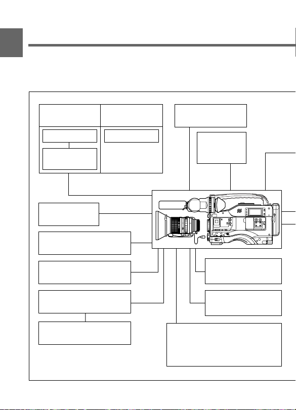
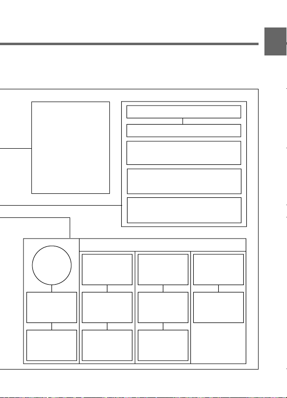
1-2 Example of System
1
Configuration
The diagram below shows a typical configuration of the camcorder for ENG and EFP.
For more information about connections of the additional equipment and accessories,
see Chapter 5, as well as the operation manuals for the connected equipment.
Video monitor
Color playback
Video monitor
Field pickup unit
Fog-proof filter
(Part No.1-547-341-11)
Servo Filter Unit
BKDW-701
RM-B150/RM-P9
Remote Control Unit
VA-DN1 Camcorder
Interface Adaptor
BVR-3
Remote Control Unit
a) For more information, see “Viewfinder and
related equipment” (page A8).
b) A CCA-86-0.4 conversion cable (not supplied) is required for connecting the RM-P9 and VA-DN1.
Color image check
while shooting
Video monitor
b)
Extension
Board
BKW-401 Viewfinder
Rotation Bracket
BVF-VC10W
Color Viewfinder
CA-701/702/702P/
755/755P
Camera Adaptor
BSC-1
Setup Card
BKDW-702 for outputting an SDI signal
BKDW-703 for Loop Rec function
BKDW-704 for reversing the picture
orientation
790WSP only)
(DVW-709WS/709WSP/790WS/
Chapter 1 Overview1-6
Lens assembly
(Part No. A-8262-537-A)
Lens assembly
(Part No. A-8262-538-A)
Lens assembly
a)
(−2.8 D to +2.0 D)
a)
(−3.6 D to −0.8 D)
a)
(−3.6 D to +0.4 D)
(Part No. A-8267-737-A)
Lens assembly
(3 × magnification)
(−2.4 D to +0.5 D)
(Part No. A-8314-798-A)
Power source
AC
c)
power
a)
Battery
BC-1WD/1WDCE
Battery Charger
Sound signal equipment
External microphone C-74, etc.
CAC-12 Microphone Holder
Audio equipment
WRR-28H/28M/28L/810A/ 860A
UHF Portable Tuner
CCXA-53 Audio Cable
BC-210/210CE/
410/410CE
Battery Charger
BC-L100/
L100CE Battery
Charger
1
AC-550/550CE
AC Adaptor
AC-DN1/DN2A
AC Adaptor
NP-1B
Battery Pack
DC-L1
Battery Adaptor
BP-90A
Battery Pack
DC-L90
Battery Adaptor
BP-L60A/L90A
Battery Pack
c) 120 V AC or
220 to 240
V AC
Chapter 1 Overview 1-7

1-3 Precautions
Use and Storage
1
Do not subject the camcorder to severe shocks
The internal mechanism may be damaged or the body warped.
After use
Always turn off the power.
Before storing the camcorder for a long period
Remove the battery pack.
Use and storage locations
Store in a ventilated place. Avoid using or storing the camcorder in the
following places.
• Places subject to temperature extremes
• Damp places
• Places subject to severe vibration
• Near strong magnetic fields
• In direct sunlight or close to heaters for extended periods
Chapter 1 Overview1-8
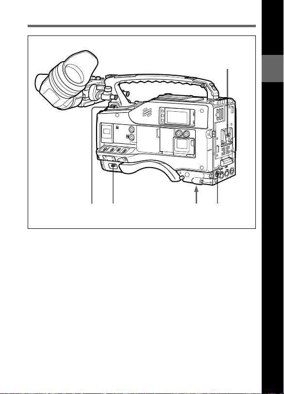
2-1 Power Supply
1
45 2
Power supply functions
1 Battery attachment
Attach a BP-L60A/L90A Battery Pack, a DC-L1 Battery Adaptor for
loading an NP-1B Battery Pack, or a DC-L90 Battery Adaptor for
loading a BP-90A Battery Pack.
Furthermore, by attaching an AC-DN1/DN2A AC Adaptor you can
operate the camcorder from AC power.
2 DC IN (external power input) connector (XLR type, 4-pin, male)
Connect an AC-550/550CE AC Adaptor with the DC output cable
supplied with the adaptor.
To use an external battery, connect its DC output cable to the DC IN
connector.
3
2
Locations and Functions of Parts and Controls
Chapter 2 Locations and Functions of Parts and Controls 2-1

3 BREAKER button
Excessive current in the internal circuitry, whatever the cause, will trip
the internal circuit breaker, automatically cutting off the power. If the
breaker trips, consult your Sony service personnel.
2
4 POWER switch
This switch turns the main power supply on and off.
5 LIGHT switch
This selects the way in which a video light connected to the LIGHT
connector is switched on and off.
AUTO: When the video light switch is turned on, starting recording with
the VTR turns on the light.
MANUAL: The video light switch controls the light, turning it on and
off manually.
Chapter 2 Locations and Functions of Parts and Controls2-2

2-2 Accessory Attachments
1 2
9
Lens cable clamps
Accessory attachments
1 Shoulder strap posts
Attach the supplied shoulder strap to these posts.
2 Light shoe
Attach a video light, etc. to this shoe.
2
3
4
5
6
7
8
Chapter 2 Locations and Functions of Parts and Controls 2-3

3 LIGHT connector
Connect the cable of a video light attached to the light shoe. The
maximum power consumption allowable for the video light is 50 W.
2
4 Lens mount
This is a special bayonet type lens mount.
5 Lens locking lever
After inserting the lens in the lens mount, rotate the lens mount ring with
this lever to lock the lens in position.
6 Lens mount cap
Remove this cap by pushing up on the lens locking lever. For protection
from dust, always insert this cap when no lens is mounted.
7 LENS connector (12-pin)
Fit the lens cable to this connector. Contact your Sony representative for
more information about the lens you are using.
8 Tripod mount
Fit the supplied tripod adaptor to mount the camcorder on a tripod.
9 Shoulder pad
You can move the shoulder pad forwards or backwards by loosening the
two screws. Do this to ensure the best balance when shooting with the
camcorder on your shoulder.
Chapter 2 Locations and Functions of Parts and Controls2-4
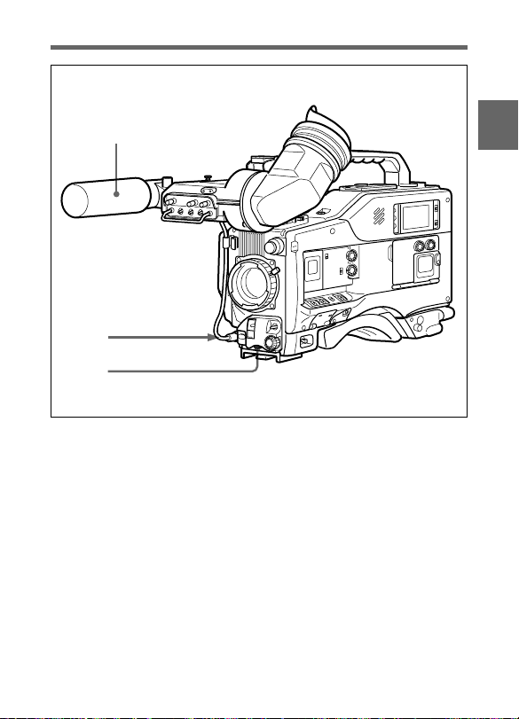
2-3 Audio Functions
1
2
3
Audio functions (1)
1 Microphone
This is a super-cardioid directional microphone with an external power
supply system. You can use it as an interview microphone by connecting
it to an extension cable (not supplied).
2 MIC IN (microphone input) connector (XLR type, 3-pin, female)
The supplied microphone connects to this connector. By using an
extension cable (not supplied), you can connect a microphone other than
the supplied one as long as it is provided with an external power supply
system. The connector supplies power (+48 V) to the microphone.
2
Chapter 2 Locations and Functions of Parts and Controls 2-5

3 MIC (microphone) AUDIO LEVEL control
If one or both of the AUDIO IN switches are set to FRONT, you can
adjust the recording level of the microphone.
When AUDIO is set to ON in the VF DISP 2/2 page of the setup menu,
2
the viewfinder DISPLAY switch is set to ON, MONITOR switch is set
to CH1, you can adjust the channel-1 audio level while watching the
indication in the viewfinder.
Chapter 2 Locations and Functions of Parts and Controls2-6
CH-1
CH-2
LEVEL
•
•
•
•
•
•
•
10
AUTO
MANUAL
AUDIO SELECT
AUDIO IN
FRONT
REAR
CUE IN
MIX
•
•
•
•
•
•
•
•
•
•
0
10
4
5
6
CH-2
7
•
•
•
•
•
0
TIME
NO.
CH-1
REGEN
PRESET
CLOCK
DIAG
DF
NDF
ADVANCE
F-RUN
R-RUN
U-BIT
SHOT
SET
DISPLAY
SHIFT
DATA
8
9
0
Illustration: DVW-707/709WS/790WS (for the NTSC broadcast system)
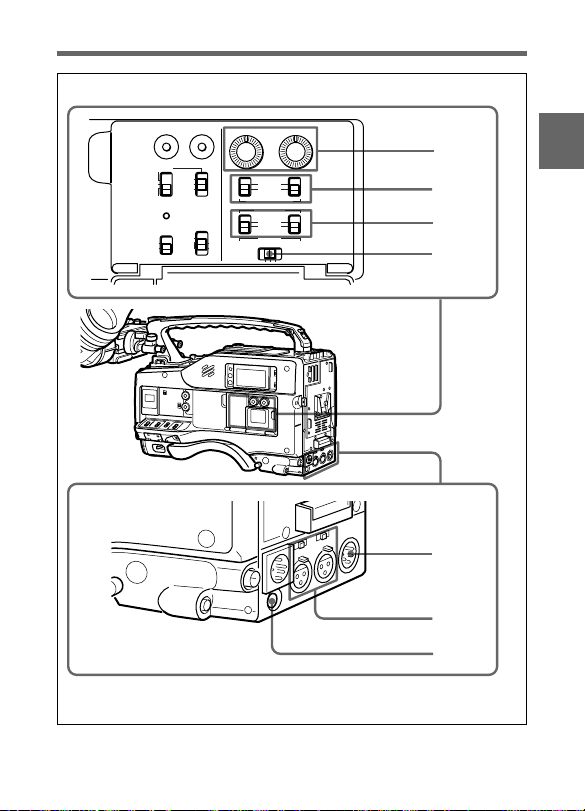
Audio functions (2)
2
Chapter 2 Locations and Functions of Parts and Controls 2-7

4 AUDIO LEVEL CH-1/CH-2 (audio channel 1 and channel 2
recording level) controls
These controls adjust the audio level of channels 1 and 2 when you set
the AUDIO SELECT CH-1/CH-2 switches to MANUAL.
2
5 AUDIO SELECT CH-1/CH-2 (audio channel-1 and channel-2
select) switches
These switches set the audio level adjustment for channels 1 and 2 to
MANUAL or AUTO.
AUTO: Select this setting for automatic adjustment.
MANUAL: Select this setting for manual adjustment.
6 AUDIO IN (audio input) switches
These switches select the audio input signals for audio channels 1 and 2.
The input signal source is one of:
FRONT: The input signal source is the MIC IN connector.
REAR: The input signal source is the AUDIO IN CH-1/CH-2
connectors.
The audio input signals from the MIC IN connector are always recorded
on audio channels 3 and 4, respectively, whether or not they are recorded
on audio channels 1 and 2 in accordance with the setting of this switch.
With the CA-701 (not supplied) connected to the camcorder, you can
record separate sounds to audio channels 3 and 4.
For more information, refer to “maintenance manual.”
7 CUE IN (cue track input) switch
This switch selects the input signals for recording the cue track.
CH-1 : Channel 1 input signal
MIX : Mixed input signal of channels 1 and 2
CH-2 : Channel 2 input signal
Chapter 2 Locations and Functions of Parts and Controls2-8

8 AUDIO OUT (audio output) connector (XLR type, 5-pin, male)
This connector outputs the stereo sound.
Using a CCXA-53 Audio Cable (not supplied), you can convert from a
5-pin connection to two 3-pin connections.
9 AUDIO IN CH-1/CH-2 (audio channel 1 and channel 2 input)
connectors (XLR type, 3-pin, female) and LINE/MIC/+48 V ON
(line input/microphone input/external power supply +48 V on)
selectors
These are the audio input connectors for channels 1 and 2, to which you
can connect a microphone or other audio sources.
The LINE/MIC/+48 V ON selectors select the audio input signal source
connected to these connectors, as follows:
LINE: Line input from an audio component
MIC: A microphone with internal batteries
+48 V ON: A microphone with an external power supply system
q; DC OUT (DC power output) connector
This connector supplies power for a WRR-28H/28M/28L/810/860A
UHF Portable Tuner (not supplied).
Alternatively, it can supply power for a BVR-3 Remote Control Unit
combined with a VA-DN1 Camcorder Interface Adaptor.
Note
The type of UHF portable tuner which can be connected depends on the
country where the camcorder is used.
For more information, consult your Sony representative.
2
Chapter 2 Locations and Functions of Parts and Controls 2-9
2
qd qaqs
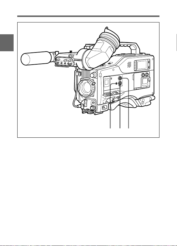
Audio functions (3)
qa ALARM volume control
This control adjusts the speaker or earphone alarm volume. At the
minimum position, no sound can be heard.
You can adjust the internal volume control so that the alarm is audible
even at the minimum setting of the ALARM volume control.
For more information, refer to “maintenance manual.”
Chapter 2 Locations and Functions of Parts and Controls2-10
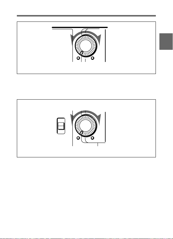
Minimum Maximum
ALARM volume control
qs MONITOR volume control
This control adjusts the speaker or earphone sound volume, excluding
the alarm sound. At the minimum position, no sound can be heard.
MONITOR
CH-1
MIX
CH-2
Minimum Maximum
MONITOR volume control
2
Chapter 2 Locations and Functions of Parts and Controls 2-11
qd MONITOR (audio channels select) switch
This switch selects the audio output to the speaker or earphone. The
audio level indication in the viewfinder screen switches automatically
according to the selection.
2
CH-1: Audio channel 1
MIX: Mixed sound of channels 1 and 2
CH-2: Audio channel 2
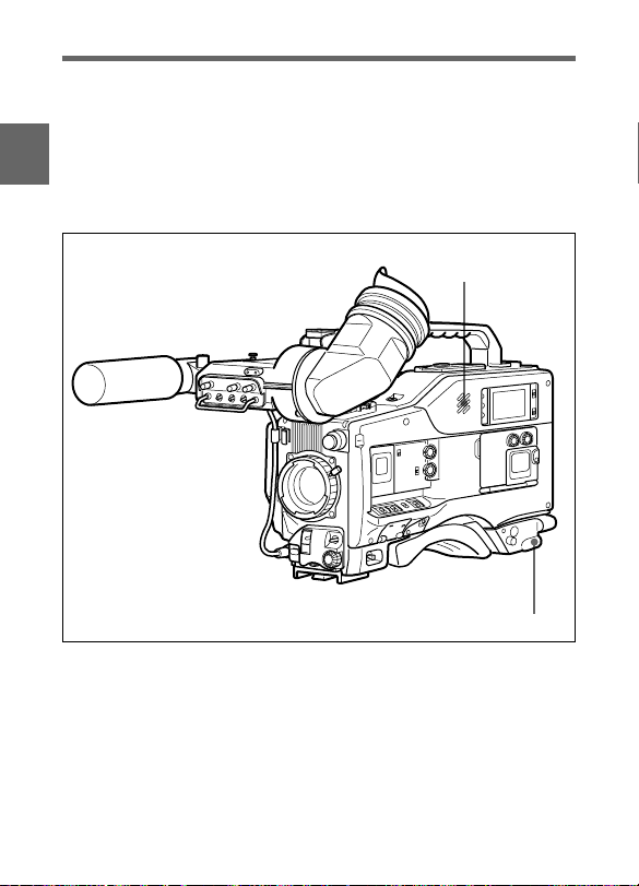
Audio functions (4)
qf
qg
Chapter 2 Locations and Functions of Parts and Controls2-12

qf Built-in speaker
During recording, the speaker can be used for monitoring the E-E sound 1),
and during playback for monitoring one or both audio channels. The
speaker also sounds alarms to reinforce visual warnings.
If an earphone is plugged into the EARPHONE jack, the speaker sound
is automatically cut off.
See Section 6-3 “Operation Warnings” (page 6-12) for information about alarms.
qg EARPHONE jack
Plugging an earphone into the jack automatically cuts off the built-in
speaker, and you hear the alarms about the camcorder’s operation and
status through the earphone.
....................................................................................................................................
1) E-E sound (Electric to Electric sound)
The term E-E sound refers to an audio signal that has passed through the
amplifier, but has not been recorded on the tape. In other words, you can directly
monitor the recording input signal, as opposed to the simultaneous playback
(output) signal.
2
Chapter 2 Locations and Functions of Parts and Controls 2-13
2-4 Shooting and Recording/
Playback Functions
2
1
2
3
4
5
7
8
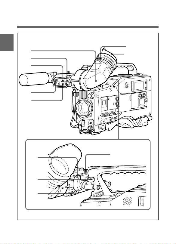
9
6
Eyecup
0
Shooting and recording/playback functions (1)
Chapter 2 Locations and Functions of Parts and Controls2-14
 Loading...