

Sony DVW-700P, DVW-700WSP, DVW-700, DVW-700WS User Manual

DIGITAL BETACAM CAMCORDER
DVW-700
DVW-700P
DVW-700WS
DVW-700WSP
Digital 1000
OPERATION MANUAL English
1st Edition (Revised 2)

WARNING
To prevent fire or shock hazard, do not
expose the unit to rain or moisture.
To avoid electrical shock, do not open
the cabinet.
LITHIUM BATTERY
Should only be changed by technical personnel.
There is a risk of explosion if handled improperly.
LITIUMBATTERI
Bör endast bytas av servicepersonal. Explosionsfara vid
felaktig hantering.
ADVARSEL!
Lithiumbatteri - Eksplosionsfare
Udskiftning må kun foretages af en sagkyndig, og
som beskrevet i servicemanualen.

For the customers in USA
This equipment has been tested and found to comply
with the limits for a Class A digital device, pursuant to
Part 15 of the FCC Rules. These limits are designed to
provide reasonable protection against harmful
interference when the equipment is operated in a
commercial environment. This equipment generates,
uses, and can radiate radio frequency energy and, if not
installed and used in accordance with the instruction
manual, may cause harmful interference to radio
communications. Operation of this equipment in a
residential area is likely to cause harmful interference in
which case the user will be required to correct the
interference at his own expense.
You are cautioned that any changes or modifications not
expressly approved in this manual could void your
authority to operate this equipment.
The shielded interface cable recommended in this
manual must be used with this equipment in order to
comply with the limits for a digital device pursuant to
Subpart B of Part 15 of FCC Rules.
For the customers in Canada
This apparatus complies with the Class A limits for radio
noise emissions set out in Radio Interference
Regulations.

Table of Contents
Chapter 1 Overview
1-1 Features .....................................................................................1-1
1-1-1 Camera Features ..............................................................1-1
1-1-2 VTR Features ..................................................................1-3
1-2 Example of System Configuration ..........................................1-4
1-3 Precautions ................................................................................1-6
Chapter 2 Locations and Functions of Parts and
Controls
2-1 Power Supply ............................................................................2-1
2-2 Accessory Attachments ............................................................2-3
2-3 Audio Functions ........................................................................ 2-5
2-4 Shooting and Record / Playback Functions .........................2-15
2-5 Setup Menu Operating Section .............................................2-27
2-6 Time Code System ..................................................................2-29
2-7 Warnings and Indications......................................................2-34
2-8 Warnings and Indications on the Display Panel..................2-37
Chapter 3 Recording and Playback
3-1 About Cassettes.........................................................................3-1
3-1-1 Loading and Unloading a Cassette .................................. 3-1
3-1-2 Preventing Accidental Erasure ........................................3-4
3-2 Recording ..................................................................................3-5
3-2-1 Basic Procedure ............................................................... 3-5
3-2-2 Continuous Recording ..................................................... 3-9
3-3 Checking the Recording — Playback ...................................3-12
3-3-1 Checking the Last Few Seconds of the Recording —
Recording Review .........................................................3-12
3-3-2 Checking the Recording on the Color Video Monitor —
Playback in Color ..........................................................3-13
Table of Contents 1

Chapter 4 Adjustments and Settings for
Recording
4-1 Adjusting the Black Balance and the White Balance............4-1
4-1-1 Adjusting the Black Balance ...........................................4-2
4-1-2 Adjusting the White Balance .......................................... 4-6
4-2 Setting the Electronic Shutter ...............................................4-12
4-2-1 Shutter Modes ...............................................................4-12
4-2-2 Selecting the Shutter Mode and Speed..........................4-14
4-3 Changing the Reference Value for Automatic Iris
Adjustment ..............................................................................4-20
4-4 Adjusting the Audio Level .....................................................4-22
4-5 Setting the Time Data.............................................................4-25
4-5-1 Setting the User Bits......................................................4-25
4-5-2 Setting the Time Code ................................................... 4-27
4-5-3 Saving the Real Time in the VITC ................................ 4-29
4-5-4 Synchronizing the Time Code ....................................... 4-31
4-6 Setup Menu Display on the Viewfinder Screen ...................4-36
4-6-1 Setup Menu Configuration ............................................4-36
4-6-2 Basic Use of the Setup Menu ........................................4-39
4-7 Indicators in the Viewfinder..................................................4-44
4-7-1 Layout of Indicators in the Viewfinder .........................4-44
4-7-2 Setting the Indicator................................................4-46
4-8 Status Display on the Viewfinder Screen .............................4-49
4-8-1 Layout of the Status Display on the Viewfinder
Screen ............................................................................4-50
4-8-2 Selecting the Display Items ........................................... 4-54
4-8-3 Display Mode and Setting Change and Adjustment
Progress Messages ........................................................4-57
4-8-4 Setting the Marker Display ...........................................4-59
4-8-5 Setting the Camera ID ...................................................4-61
4-9 Adjustments and Settings From the Setup Menu................4-66
4-9-1 Setting the GAIN Selector Values ................................4-67
2 Table of Contents

4-9-2 Selecting the Functions .................................................4-69
4-9-3 Selecting the Test Output ..............................................4-72
4-9-4 Selecting the Aspect Ratio (DVW-700WS / 700WSP
Only) ............................................................................. 4-74
4-10 Using the Setup Card .............................................................4-78
4-10-1Handling the Setup Card ...............................................4-78
4-10-2Using Data on the Setup Card .......................................4-80
Chapter 5 Setting Up the Camcorder
5-1 Power Supply ............................................................................5-1
5-1-1 Using a BP-L60 / L90 Battery Pack ................................ 5-1
5-1-2 Using an NP-1B / 1A Battery Pack .................................5-4
5-1-3 Using a BP-90A / 90 Battery Pack .................................. 5-6
5-1-4 Avoiding Breaks in Operation Due to Dead Batteries ....5-7
5-1-5 Using an AC Adaptor ......................................................5-8
5-1-6 Using the Anton Bauer Intelligent Battery System and
Ultralight System ............................................................ 5-9
5-2 Adjusting the Viewfinder ....................................................... 5-10
5-2-1 Adjusting the Viewfinder Position ................................5-10
5-2-2 Adjusting the Viewfinder Focus and Screen ................. 5-13
5-2-3 Detaching the Viewfinder .............................................5-14
5-2-4 Detaching the Eyepiece .................................................5-16
5-3 Mounting the Lens..................................................................5-18
5-4 Adjusting the Flange Focal Length ....................................... 5-19
5-5 Audio Input System ................................................................5-21
5-5-1 Using the Supplied Microphone....................................5-21
5-5-2 Using an External Microphone .....................................5-24
5-5-3 Attaching a UHF Portable Tuner (for a UHF Wireless
Microphone System) ..................................................... 5-29
5-5-4 Connecting Line Input Audio Equipment .....................5-33
5-6 Tripod Mounting ....................................................................5-34
5-7 Attaching the Shoulder Strap ................................................ 5-36
5-8 Adjusting the Shoulder Pad Position ....................................5-38
5-9 Putting On the Rain Cover ....................................................5-39
Table of Contents 3

5-10 Connecting the Remote Control Unit ................................... 5-42
Chapter 6 Maintenance
6-1 Testing the Camcorder Before Shooting ................................6-1
6-1-1 Preparations for Testing .................................................. 6-1
6-1-2 Testing the Camera ......................................................... 6-2
6-1-3 Testing the VTR ..............................................................6-6
6-2 Maintenance ............................................................................ 6-10
6-2-1 Cleaning the Video Heads ............................................. 6-10
6-2-2 Cleaning the Viewfinder ...............................................6-10
6-3 Operation Warnings...............................................................6-12
Appendix
Specifications......................................................................................A-1
Video Camera Section ...............................................................A-2
VTR Section ..............................................................................A-4
Supplied Accessories .................................................................A-7
Recommended Additional Equipment.......................................A-7
Glossary ............................................................................................A-10
Index.....................................................................................................I-1
4 Table of Contents

1-1 Features
The DVW-700 series 1) Digital BETACAM Camcorder combines a color
video camera, which uses FIT 2) type Hyper HAD
with a Digital BETACAM series portable videocassette recorder. Its
excellent image quality, sensitivity, portability, and dust- and waterproof construction make it ideal as a camcorder for ENG 5) and EFP 6) in
the same way as its predecessor, the BVW-400 / 400P. The introduction
of a new method of processing digital signals improves the image quality
even further and makes the camcorder far easier to use.
The DVW-700WS / 700WSP combine the basic design of its predecesor,
the DVW-700 / 700P, with a new switchable CCD that allows you to
select between a conventional ratio aspect of 4:3 and a wide screen ratio
aspect of 16:9.
3)
1000 sensor CCDs 4),
1-1-1 Camera Features
The features of the DVW-700 series camera are described below.
• FIT-type Hyper HAD sensor CCDs ensure the very best possible image
quality.
• Digital signal processing has improved picture quality, stability, and
reliability.
• A setup menu enables you to control features such as status displays,
messages, and markers; to select values or functions; and to operate a
setup card.
• A setup card makes it easy to replicate the recorder setup data
appropriate to the shooting conditions, and ensures uniform shooting.
....................................................................................................................................
1) The DVW-700 / 700WS are for the NTSC broadcast system. The DVW-700P /
700WSP are for the PAL broadcast system. The descriptions given in this
manual apply to both models, any differences being clearly noted in the text.
2) FIT : Frame Interline Transfer
3) Hyper HAD : Hyper Hole-Accumulated Diode
“Hyper HAD” is a trademark of Sony Corporation.
4) CCD : Charge-Coupled Device
5) ENG : Electronic News Gathering
6) EFP : Electronic Field Production
1
Overview
Chapter 1 Overview 1-1

• Use of a built-in sophisticated electronic shutter, which has selectable
1
modes, Clear Scan 1), Extended Clear Scan, and Super Enhanced
Vertical Definition, ensures shooting with little or no blurring.
• Selectable video gain ensures a noise-free image.
• A simple switch operation enables automatic adjustment of the black
set, black balance, and white balance. Memory functions make it easy
to replicate the settings appropriate for the lighting conditions.
• Automatic shading adjustment.
• A high-performance viewfinder is adjustable forward, backward and
sideways, and has full auxiliary equipment.
• Character display functions on the viewfinder indicate switch settings,
black and white balance adjustment, and warnings.
• Warning indicators and sound inform you of VTR faults, end of tape,
low battery, etc.
• A standard double-layer filter disc is provided to select the filter most
suitable for the brightness of the subject.
• Fine adjustment of the reference value for automatic iris control is
provided.
• The iris of the lens automatically closes during automatic black balance
adjustment and during operation of the built-in saw-tooth waveform
generator.
• A built-in circuit produces a color bar signal for easy adjustment of the
color monitor.
• A super-cardioid directional microphone with an external power supply
system is supplied. Other types of microphones can also be connected.
• A remote control unit controls some of the camera functions.
....................................................................................................................................
1) Clear Scan : “Clear Scan” is a trademark of Sony Corporation.
1-2 Chapter 1 Overview

1-1-2 VTR Features
The VTR features of the DVW-700 series are described below.
• Digital BETACAM format gives improved signal-to-noise ratio,
frequency bandwidth, waveform characteristics, and detail playback
characteristics to ensure higher video and audio quality.
• After the last few seconds of recording, the VTR automatically rewinds
and then plays back by pressing the RET button on the lens. This
function enables a quick check of the recording.
• No playback adaptor is needed to see the color playback image.
• The 5 times normal speed search function provides quick positioning
of the tape.
• Both LTC 1) and VITC 2) recordings can be made, as can LTC
playback.
• The built-in time code generator is synchronized with an external
generator.
• A lithium battery is the back-up power supply for the time code
generator enabling the time code to be held for about 5 years without
charging the camcorder power supply.
• Optional long-life battery packs are available.
• Pressing the VTR START button on the camcorder or the VTR button
on the lens ensures recording continuity from the very next frame.
1
....................................................................................................................................
1) LTC : Longitudinal Time Code
2) VITC : Vertical Interval Time Code
Chapter 1 Overview 1-3
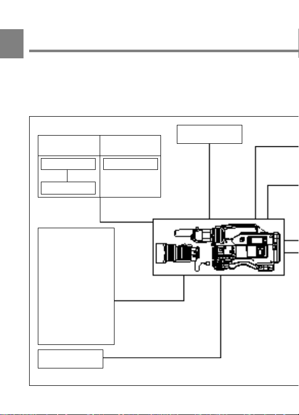
1-2 Example of System
1
Configuration
The diagram below shows a typical configuration of the camcorder for
ENG and EFP.
For more information about connections of the additional equipment and
accessories, see Chapter 5, as well as the operation manuals for the connected
equipment.
Video monitor
Color playback
Video monitor
Field pickup unit
Lens assembly
(−2.8 D to +2.0 D)
(Part No. A-8262-537-A)
Lens assembly
(−3.6 D to −0.8 D)
(Part No. A-8262-538-A)
Lens assembly
(−3.6 D to +0.4 D)
(Part No. A-8267-737-A)
Lens assembly
(3 × magnification)
(−3.6 D to +0.4 D)
(Part No. A-8314-798-A)
RM-P9
Remote Control Unit
a) For more information, see “Viewfinder and related equipment” (page A-8).
Color image check
while shooting
Video monitor
a)
a)
a)
a)
BKW-401 Viewfinder
Rotation Bracket
1-4 Chapter 1 Overview

1
Left-eye shooting
viewfinder slide guide
(Part No. A-8262-535-A)
Fog-proof filter
(Part No. 1-547-341-11)
Power source
AC
b)
power
AC-550 / 550CE
AC Adaptor
b) 120 V AC or 220
to 240 V AC
Battery
BC-1WD
Battery Charger
NP-1B / 1A
Battery Pack
DC-L1
Battery Adaptor
Sound signal source
External microphone
C-74, etc.
CAC-12
Microphone Holder
Audio equipment
WRR-28H / 28M / 28L /
810A / 860A
UHF Portable Tuner
BC-210 / 210CE /
410 / 410CE
Battery Charger
BP-90A / 90
Battery Pack
DC-L90
Battery Adaptor
BC-L100 /
L100CE Battery
Charger
BP-L60 / L90
Battery Pack
Chapter 1 Overview 1-5

1-3 Precautions
Use and Storage
1
Do not subject the camcorder to severe shocks
The internal mechanism may be damaged or the body warped.
After use
Always turn off the power.
Before storing the camcorder for a long period
Remove the battery pack.
Use and storage locations
Store in a ventilated place. Avoid using or storing the camcorder in the
following places.
• Places subject to temperature extremes
• Damp places
• Places subject to severe vibration
• Near strong magnetic fields
• In direct sunlight or close to heaters for extended periods
1-6 Chapter 1 Overview
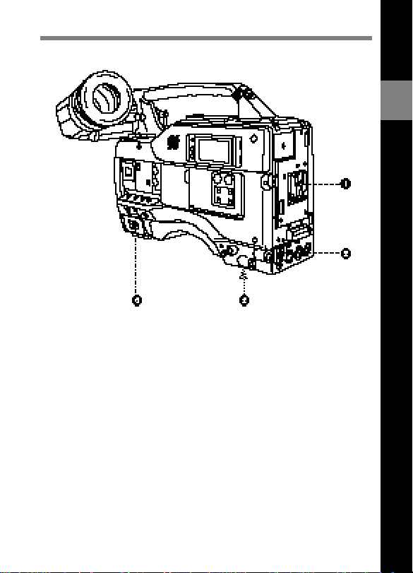
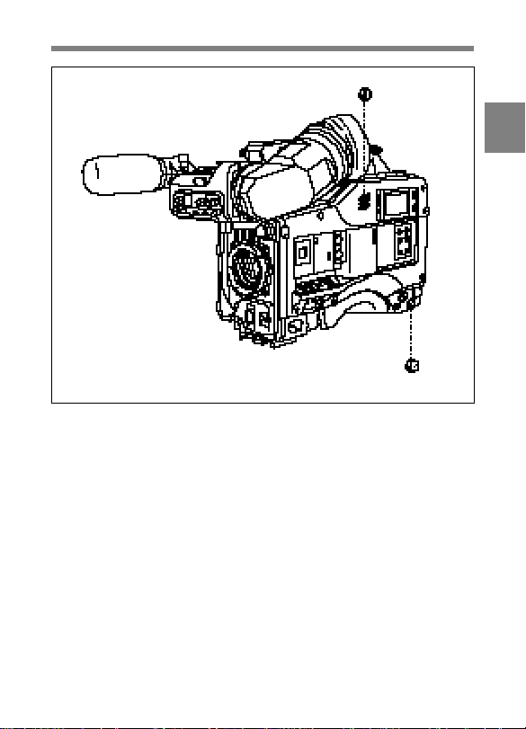
2-1 Power Supply
Power supply functions
1 Battery attachment
Attach a BP-L60 / L90 Battery Pack, a DC-L1 Battery Adaptor loaded
with an NP-1B / 1A Battery Pack, or a DC-L90 Battery Adaptor loaded
with a BP-90A / 90 Battery Pack.
2
Locations and Functions of Parts and Controls
2 DC IN (external power input) connector (XLR type, 4-pin, male)
Connect an AC-550 / 550CE AC Adaptor with the DC output cable
supplied with the adaptor.
To use an external battery, connect its DC output cable to the DC IN
connector.
Chapter 2 Locations and Functions of Parts and Controls 2-1

3 BREAKER button
Excessive current in the internal circuitry, whatever the cause, will trip
the internal circuit breaker, automatically cutting off the power. After
checking that the problem has been corrected, press this button. The
2
power should come on again.
4 POWER switch
This switch turns the main power supply on and off.
2-2 Chapter 2 Locations and Functions of Parts and Controls

2-2 Accessory Attachments
Lens cable clamps
Accessory attachments
1 Shoulder strap posts
Attach the supplied shoulder strap to these posts.
2 Light shoe
Attach a video light, etc. to this shoe.
2
3 Lens mount
This is a special bayonet type lens mount.
4 Lens locking lever
After inserting the lens in the lens mount, rotate the lens mount ring with
this lever to lock the lens in position.
Chapter 2 Locations and Functions of Parts and Controls 2-3

5 Lens mount cap
Remove this cap by pushing up on the lens locking lever. For protection
from dust, always insert this cap when no lens is mounted.
2
6 Tripod mount
Fit the supplied tripod adaptor to mount the camcorder on a tripod.
7 LENS connector (12-pin)
Fit the lens cable to this connector. Contact your Sony representative for
more information about the lens you are using.
8 Shoulder pad
You can move the shoulder pad forwards or backwards by loosening the
two screws. Do this to ensure the best balance when shooting with the
camcorder on your shoulder.
2-4 Chapter 2 Locations and Functions of Parts and Controls
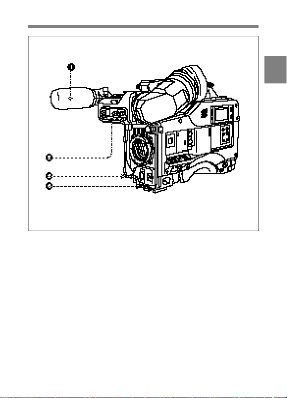
2-3 Audio Functions
Audio functions (1)
1 Microphone
This is a super-cardioid directional microphone with an external power
supply system. You can use it as an interview microphone by connecting
it to an extension cable (not supplied).
2
2 AUDIO IND (audio channel-1 recording level indicator) switch
This switch determines whether the recording level of audio channel-1 is
displayed on the viewfinder screen.
ON : The recording level is displayed.
OFF : The recording level is not displayed.
Chapter 2 Locations and Functions of Parts and Controls 2-5

3 MIC IN (microphone input) connector (mini XLR type, 3- pin,
female)
The supplied microphone connects to this connector. By using an
extension cable (not supplied), you can connect a microphone other than
2
the supplied one as long as it is a super cardioid microphone with an
external power supply system. The connector supplies power (+48 V) to
the microphone.
4 MIC (microphone) AUDIO LEVEL control
If the AUDIO IN switches are both set to FRONT, you can adjust the
recording level of the microphone.
If the AUDIO IND switch is set to ON, you can watch the audio level
display in the viewfinder while adjusting the level.
2-6 Chapter 2 Locations and Functions of Parts and Controls
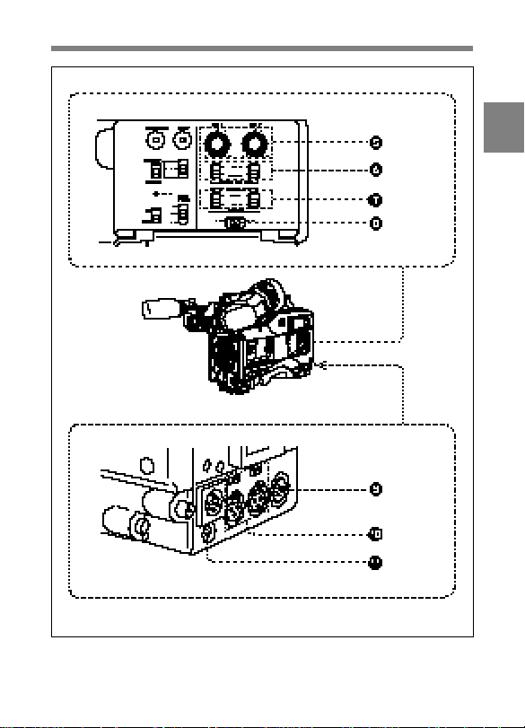
Audio functions (2)
2
Chapter 2 Locations and Functions of Parts and Controls 2-7

5 AUDIO LEVEL CH-1 / CH-2 (audio channel 1 and channel 2
recording level) controls
These controls adjust the audio level of channels 1 and 2 when you set
the AUDIO SELECT CH-1 / CH-2 switches to MAN.
2
6 AUDIO SELECT CH-1 / CH-2 (audio channel-1 and channel-2
select) switches
These switches set the audio level adjustment for channels 1 and 2 to
MANUAL or AUTO.
7 AUDIO IN (audio input) switches
These switches select the audio input signals for audio channels 1 and 2.
The input signal source is either:
FRONT : The input signal source is the MIC IN connector.
REAR : The input signal source is the AUDIO IN CH-1 / CH-2
connectors.
8 CUE IN (cue track input) switch
This switch selects the input signals for recording the cue track.
CH-1 : Channel 1 input signal
MIX : Mixed input signal of channels 1 and 2
CH-2 : Channel 2 input signal
9 AUDIO OUT (audio output) connector (XLR type, 3-pin, male)
This connector outputs the sound selected by the MONITOR switch.
2-8 Chapter 2 Locations and Functions of Parts and Controls

0 AUDIO IN CH-1 / CH-2 (audio channel 1 and channel 2 input)
connectors (XLR type, 3-pin, female) and LINE / MIC / +48 V
ON (line input / microphone input / external power supply +48 V
on) selectors
These are the audio input connectors for channels 1 and 2, to which you
can connect a microphone or other audio sources.
The LINE / MIC / +48 V ON selectors select the audio input signal
source connected to these connectors, as follows:
LINE : Line input audio equipment
MIC : A microphone with internal batteries
+48 V ON : A microphone with an external power supply system
!¡ DC OUT (DC power output) connector
This connector supplies power for a WRR-28H / 28M / 28L / 860A UHF
Portable Tuner (not supplied). Do not connect anything other than a UHF
portable tuner to this connector.
Note
The type of UHF portable tuner which can be connected depends on the
country where the camcorder is used.
For more information, consult your Sony representative.
2
Chapter 2 Locations and Functions of Parts and Controls 2-9

2
Audio functions (3)
2-10 Chapter 2 Locations and Functions of Parts and Controls

!™ ALARM volume control
This control adjusts the speaker or earphone alarm volume. At the
minimum position, no sound can be heard.
Minimum Maximum
ALARM volume control
You can adjust the internal volume control so that the alarm is audible
even at the minimum setting of the ALARM volume control.
Refer to the Maintenance Manual for more information.
2
Chapter 2 Locations and Functions of Parts and Controls 2-11

!£ MONITOR volume control
This control adjusts the speaker or earphone sound volume, excluding
the alarm sound. At the minimum position, no sound can be heard.
2
Minimum Maximum
MONITOR volume control
!¢ MONITOR (audio channels select) switch
This switch selects the audio output to the speaker or earphone.
CH-1 : Audio channel 1
MIX : Mixed sound of channels 1 and 2
CH-2 : Audio channel 2
2-12 Chapter 2 Locations and Functions of Parts and Controls
Audio functions (4)
!∞ Built-in speaker
During recording, the speaker can be used for monitoring the E-E sound 1),
and during playback for monitoring one or both audio channels. The
speaker also sounds alarms to reinforce visual warnings.
If an earphone is plugged into the EARPHONE jack, the speaker sound
is automatically cut off.
See Section 6-3 “Operation Warnings” (page 6-12) for information about alarms.
....................................................................................................................................
1) E-E sound (Electric to Electric sound)
The term E-E sound refers to an audio signal that has passed through the
amplifier, but has not been recorded on the tape. In other words, you can directly
monitor the recording input signal, as opposed to the simultaneous playback
(output) signal.
2
Chapter 2 Locations and Functions of Parts and Controls 2-13

!§ EARPHONE jack
Plugging an earphone into the jack automatically cuts off the built-in
speaker, and you hear the alarms about the camcorder’s operation and
status through the earphone.
2
2-14 Chapter 2 Locations and Functions of Parts and Controls
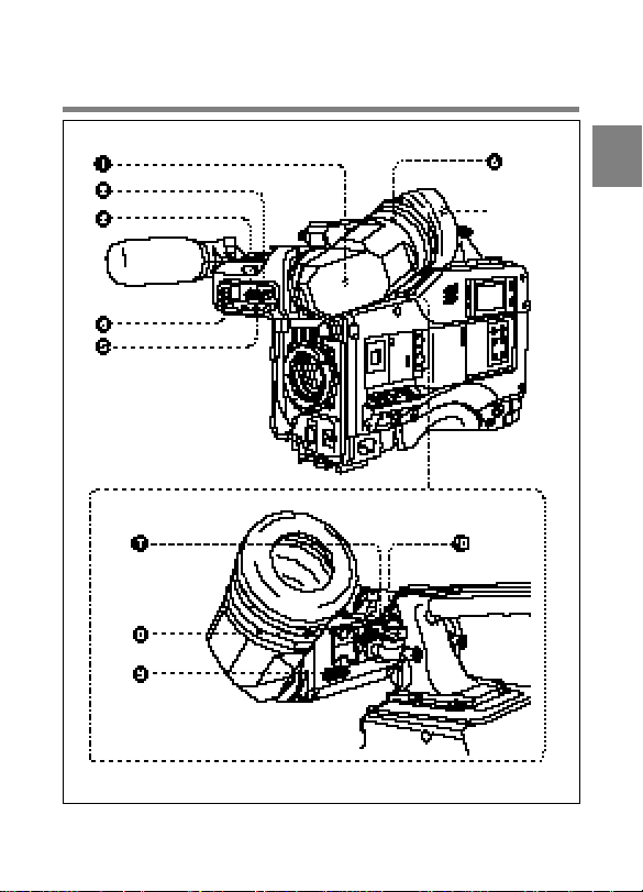
2-4 Shooting and Record /
Playback Functions
Eyecup
2
Shooting and record / playback functions (1)
Chapter 2 Locations and Functions of Parts and Controls 2-15

1 Viewfinder
The viewfinder lets you view the camera image in black and white while
shooting the picture and also see the playback picture from the VTR. It
also displays various warnings and other information, a zebra pattern 1),
2
safety zone marker 2), and center marker 3).
2 BRIGHT (brightness) control
This control adjusts the picture brightness on the viewfinder screen. It
has no effect on the camera output signal.
3 CONTRAST control
This control adjusts the picture contrast on the viewfinder screen. It has
no effect on the camera output signal.
4 PEAKING control
This control adjusts the sharpness of the picture on the viewfinder screen
to make focusing easier. It has no effect on the camera output signal.
....................................................................................................................................
1) Zebra pattern
The zebra pattern aids in manual iris adjustment by indicating areas of the
picture where the video level is approximately 70 % IRE (for the DVW-700 /
700WS) or 490 mV (for the DVW-700P / 700WSP).
2) Safety zone marker
The safety zone marker is a rectangle indicating the effective picture area which
is equivalent to 80 % or 90 % (the factory setting) of the entire viewfinder
screen area. A setup menu lets you change the effective picture area from 90 %
to 80 %.
For more information, see Section 4-8-4 “Setting the Marker Display” (page 4-
59).
3) Center marker
The center marker indicates the center of the picture with a crosshair.
2-16 Chapter 2 Locations and Functions of Parts and Controls

5 ZEBRA (zebra pattern) switch
This switch controls the zebra pattern on the viewfinder screen.
ON : The zebra pattern is displayed and stays.
OFF : No zebra pattern is displayed.
MOMENT : The zebra pattern is displayed and stays for a few seconds.
The zebra pattern display is factory set to indicate picture areas where
the video level is approximately 70 % IRE (for the DVW-700 /
700WS) or 490 mV (for the DVW-700P / 700WSP).
Note that a setup menu can be used to set it to simultaneously indicate
areas of 100 % IRE (for the DVW-700 / 700WS) and above, or 700
mV (for the DVW-700P / 700WSP) and above.
For more information, refer to the Maintenance Manual.
6 Diopter adjustment ring
Use this ring to adjust the viewfinder image for your vision.
7 Viewfinder left-right positioning ring
Use this ring to move the viewfinder sideways.
8 Viewfinder front-rear positioning lever
Use this lever to move the viewfinder forward or backward.
9 Cameraman tally indicator
This indicator lights while the camcorder is operating.
Slide the window open when you shoot, keeping your eye away from the
viewfinder.
0 Viewfinder stopper
Pull this stopper up to detach the viewfinder from the camera.
2
Chapter 2 Locations and Functions of Parts and Controls 2-17
 Loading...