

Page 1
SONy
DVS-7250
Product Guide
Page 2

SONy
DVS-7250 • Product Guide
Copyright
Part Number BC-00639
Revision A, October 1997
Printed in U.S.A.
© 1997 Sony Electronics Inc. All rights reserved.
Neither this guide nor the software described herein, in whole or in part, may be
reproduced, translated or reduced to any machine readable form without prior
written approval from Sony Electronics Inc.
• Sony is a registered trademark of Sony Electronics Inc.
• Betacam, Betacart, Jumbotron, and Umatic are registered trademarks
of Sony Electronics Inc.
• FineChroma, FlexiPad, Digital BETACAM, E-File, DME-LINK and
Library Management System are trademarks of Sony Electronics Inc.
• ISR (Interactive Status Reporting) is an equipment management
system developed by Sony Electronics Inc.
• Abekas is a registered trademark of Scitex Digital Video. Dveous is a
trademark of Scitex Digital Video.
• GVG is a registered trademark of The Grass Valley Group Inc.
Notice to Users
SONY PROVIDES NO WARRANTY WITH REGARD TO THIS GUIDE, THE
SOFTWARE OR OTHER INFORMATION CONTAINED HEREIN, AND
HEREBY EXPRESSLY DISCLAIMS ANY IMPLIED WARRANTIES OF
MERCHANTABILITY OR FITNESS FOR ANY PARTICULAR PURPOSE WITH
REGARD TO THIS GUIDE, THE SOFTWARE OR SUCH OTHER
INFORMATION. IN NO EVENT SHALL SONY BE LIABLE FOR ANY
INCIDENTAL, CONSEQUENTIAL OR SPECIAL DAMAGES, WHETHER
BASED ON TORT, CONTRACT, OR OTHERWISE, ARISING OUT OF OR IN
CONNECTION WITH THIS GUIDE, THE SOFTWARE OR OTHER
INFORMATION CONTAINED HEREIN OR THE USE THEREOF.
Sony reserves the right to make any modification to this guide or the information
contained herein at any time without notice.
The software described herein may also be governed by the terms of a separate end
use license agreement.
All features, functions, and specifications are subject to change without notice.
Page 3

Contents
Introduction 1
About This Guide................................................................................................................. 1
Features and Benefits 3
DVS-7250 Feature Overview................................................................................................3
Making Complex Tasks Simple............................................................................................4
Basic Tools ..........................................................................................................................5
Power Tools......................................................................................................................... 9
SONY
Control Panel .........................................................................................................5
Input Flexibility...................................................................................................... 5
V-Proc.................................................................................................................... 6
Output Flexibility...................................................................................................6
Effect Keyers and DSK........................................................................................... 6
Key Edge Adjustment ............................................................................................. 7
Enhanced Wipe Generator...................................................................................... 7
Snapshot, Effects Memory, and Storage.................................................................. 7
Superior Editor Interface........................................................................................8
Router Interface...................................................................................................... 8
Switchable System Standard...................................................................................9
Redundant Power Supplies .....................................................................................9
Timeline Effects..................................................................................................... 9
Integrated DME Control....................................................................................... 10
Key Modifiers....................................................................................................... 10
Advanced Chroma Keyer — FineChroma......................................................... 10
Dual Matte Generators with Color Mix Capability................................................ 11
Frame Memory ..................................................................................................... 11
Auxiliary Buses.................................................................................................... 12
Processed Key ...................................................................................................... 12
DME-LINK™...................................................................................................... 12
Bus Link Mode..................................................................................................... 13
GPI Link Mode .................................................................................................... 13
Configuration Guide 15
DVS-7250 Configuration...................................................................................................15
Basics ................................................................................................................................ 16
Video Effects Processor........................................................................................16
Control Panel — Euro Style ................................................................................. 16
Control Panel — American Style.......................................................................... 17
Operation Software with Manual.......................................................................... 17
Input Configuration ........................................................................................................... 18
12 Input Serial Digital Board................................................................................ 18
DVS-7250 • Product Guide Contents •• i
Page 4

SONY
Input “Mother Board” .......................................................................................... 18
Analog Composite “Daughter Board”................................................................... 18
Serial Digital “Daughter Board”........................................................................... 18
Chroma Key Analog Component Input Board ...................................................... 18
Output Configuration ......................................................................................................... 19
Analog Composite Output Module ....................................................................... 19
Digital Output Module ......................................................................................... 19
Control Panel Options........................................................................................................ 20
Memory Recall Control Panel............................................................................... 20
Key Frame Control Panel..................................................................................... 20
DME Control Panel.............................................................................................. 20
Operation Software and Manual (DME-3000)...................................................... 20
Operation Software and Manual (DME-7000)...................................................... 21
Control Panel Remote Adaptor............................................................................. 21
Remote Key Control Panel ................................................................................... 21
Remote Key Control Software .............................................................................. 21
Remote Panel Interface......................................................................................... 22
Shot Box Control Unit.......................................................................................... 22
Auxiliary Control Panel ....................................................................................... 22
M/E Auxiliary Control Panel................................................................................ 23
Auxiliary Panel Operation Software ..................................................................... 23
Switcher Control Panel Configuration.................................................................. 23
Options and Upgrades........................................................................................................ 24
Basic Chroma Key Board..................................................................................... 24
Chroma Key Upgrade Board ................................................................................ 24
Basic Frame Memory Board................................................................................. 24
Frame Memory Adaptor Board ............................................................................. 24
Enhanced Wipe Option ........................................................................................ 24
Program/Preset DSK Board (Required) ................................................................ 25
Key Border Option............................................................................................... 25
M/E Key Signal Preview Board............................................................................ 25
Control Port Expansion Board.............................................................................. 25
Redundant Power Supply — Control Panel .......................................................... 25
Redundant Power Supply — Processor................................................................. 25
Tally Interface Unit.............................................................................................. 26
Tally Interface Software ....................................................................................... 26
Expansion Module ............................................................................................... 26
Redundant Power Supply — Tally........................................................................ 26
Spare Parts Kit — Video Processor ...................................................................... 26
Spare Parts Kit — Control Panel.......................................................................... 27
System Cables, RS-422......................................................................................... 27
System Cables, Interconnect................................................................................. 27
Rack Mount Kit — Switcher................................................................................ 27
Rack Mount Kit — Tally...................................................................................... 27
Extender Cards .................................................................................................... 27
Training ............................................................................................................................ 28
Training — General Product................................................................................ 28
Order Guide — DVS-7250 ................................................................................................ 29
Instructions.......................................................................................................... 29
Request Forms................................................................................................................... 30
DVS-7250 Input Configuration Chart .................................................................. 30
DVS-7250 Output Configuration Chart................................................................ 31
DVS-7250 System Components Chart.................................................................. 32
ii •• Contents DVS-7250 • Product Guide
Page 5

SONY
Installation Guide 35
DVS-7250 Installation ....................................................................................................... 35
DVS-7250 Control Panel ................................................................................................... 36
Control Panel Top View — American Style ......................................................... 36
Control Panel Top View — Euro Style.................................................................41
Sub Panel Remote Installation with BKDS-7075 .................................................. 42
Control Panel External Dimensions ...................................................................... 43
Control Panel Specifications ................................................................................. 44
Control Panel Rear View...................................................................................... 45
Control Panel Connectors..................................................................................... 46
RS-422A Switcher Connector Specifications........................................... 46
RS-422A DSK Connector Specifications................................................. 47
RS-422A DME Connector Specifications ................................................ 47
RS-232C Terminal 1, 2 Connector Specifications ................................... 48
RS-422A Remote 1-5 Connector Specifications....................................... 48
GPI Connector Specifications ................................................................. 49
Option Panel Connector Specifications ................................................... 50
AUX Panel Connector Specifications...................................................... 51
Display Panel Connector Specifications .................................................. 52
Additional Control Panels.................................................................................................. 53
BKDS-2010 — M/E Auxiliary Control Panel....................................................... 54
BKDS-2010 Control Panel Top View...................................................... 54
BKDS-2010 Control Panel Rear View .................................................... 55
BKDS-2010 Control Panel External Dimensions .................................... 55
BKDS-2010 Control Panel Specifications ............................................... 56
BKDS-2010 Control Panel Connectors ................................................... 56
BKDS-7060 — Remote Key Control Panel ........................................................... 58
BKDS-7060 Control Panel Top View...................................................... 58
BKDS-7060 Control Panel External Dimensions .................................... 58
BKDS-7060 Control Panel Specifications ............................................... 59
BKDS-7060 Control Panel Rear View .................................................... 59
BKDS-7060 Control Panel Connectors ................................................... 60
BKDS-7060 Power Supply Front View ................................................... 60
BKDS-7060 Power Supply External Dimensions .................................... 61
BKDS-7060 Power Supply Specifications ............................................... 61
BKDS-7060 Power Supply Rear View..................................................... 62
BKDS-7060 Power Supply Connectors ................................................... 62
BKDS-8060 — Remote Panel Interface................................................................ 64
BKDS-8060 Front View.......................................................................... 64
BKDS-8060 Rear View........................................................................... 64
BKDS-8060 External Dimensions........................................................... 65
BKDS-8060 Specifications...................................................................... 65
BKDS-8060 Connectors.......................................................................... 66
BKDS-8061 — Shot Box Control Unit................................................................. 68
BKDS-8061 Front View.......................................................................... 68
BKDS-8061 Rear View........................................................................... 68
BKDS-8061 External Dimensions........................................................... 69
BKDS-8061 Specifications...................................................................... 69
BKDS-8061 Connectors.......................................................................... 70
BKDS-8062 — Auxiliary Control Panel............................................................... 71
BKDS-8062 Front View.......................................................................... 71
BKDS-8062 Rear View........................................................................... 71
BKDS-8062 External Dimensions........................................................... 72
DVS-7250 • Product Guide Contents •• iii
Page 6

SONY
BKDS-8062 Specifications ..................................................................... 72
BKDS-8062 Connectors ......................................................................... 73
DVS-7200 Chassis ............................................................................................................. 74
Chassis Front View.............................................................................................. 74
Chassis Rear View ............................................................................................... 75
Chassis External Dimensions............................................................................... 77
Chassis Specifications.......................................................................................... 77
System Timing Requirements............................................................................... 80
Chassis Connectors .............................................................................................. 81
RS-422A DSK Connector Specifications................................................. 81
RS-232C Terminal Connector Specifications.......................................... 82
RS-422A Serial Tally Connector Specifications...................................... 82
RS-422A Matrix Connector Specifications.............................................. 83
RS-422A DME Connector Specifications................................................ 83
RS-422A Panel 1 Connector Specifications............................................. 84
RS-422A Panel 2/Remote 3 Connector Specifications............................. 84
RS-422A Editor A/Remote 1 Connector Specifications........................... 85
RS-422A Editor B/Remote 2 Connector Specifications ........................... 85
GPI Connector Specifications ................................................................. 86
BKDS-7700 Chassis .......................................................................................................... 87
BKDS-7700 Chassis Front View .......................................................................... 87
BKDS-7700 Chassis Rear View ........................................................................... 88
BKDS-7700 Chassis External Dimensions ........................................................... 89
BKDS-7700 Chassis Specifications ...................................................................... 89
BKDS-7700 Chassis Connectors .......................................................................... 90
BKDS-7700 Terminal Connector Specifications..................................... 90
BKDS-7700 Switcher Connector Specifications...................................... 91
BKDS-7700 Through Out Connector Specifications ............................... 91
BKDS-7700 Serial Tally 1, 2 Connector Specifications........................... 92
BKDS-7700 Tally In/GPI Connector Specifications................................ 93
BKDS-7700 Tally Enable Connector Specifications ................................ 94
BKDS-7700 Tally Out 1-9 Connector Specifications............................... 95
System Interconnection Charts........................................................................................... 97
DVS-7250 System Interconnection Chart — Video.............................................. 98
DVS-7250 System Interconnection Chart — Control............................................ 99
DVS-7250 Control Panel Connections Chart .......................................................100
DVS-7250 Video Paths with Router Chart...........................................................101
DVS-7250 Switcher - Router Interface Chart.......................................................102
DVS-7250 with ScitexDV (Abekas) Dveous A-5100 ...........................................103
Appendix A. Feature List 105
DVS-7250 — Feature Review...........................................................................................105
DVS-7250 Features.............................................................................................105
Appendix B. Related Resources 109
Related Resources.............................................................................................................109
Printed Media .....................................................................................................109
Audio/Video Media.............................................................................................110
iv •• Contents DVS-7250 • Product Guide
Page 7

SONY
Appendix C. Sales and Service 111
General Information and Reference .................................................................................. 111
Regional Sales Offices...................................................................................................... 112
Regional Service Centers ................................................................................................. 113
National Parts Centers ..................................................................................................... 114
Emergency Response System............................................................................................ 115
SUPPORTNETSM........................................................................................................... 116
SOFTWAREPLUSSM ..................................................................................................... 116
Glossary 117
Index 123
DVS-7250 • Product Guide Contents •• v
Page 8

Page 9
Introduction
About This Guide
SONY
Based on the successful DVS-7000 series platform, Sony’s new DVS-7250 switcher
configuration adds a dynamic and powerful mid-range switcher to the product line.
The DVS-7250’s image quality, superb keying, timeline control, and overall
versatility pinpoints a broad range of applications, including studio production, post
production, and remote broadcast requirements. Above all, the DVS-7250 delivers
its broad range of features in a full-featured two M/E format (with Program/Preset)
— with all the input flexibility, customization capability, integrated performance,
and ease of use that you’ve come to expect from Sony digital switchers.
To assist you with configuring the optimum mid-range SDI switcher for your
customer’s needs, this guide is divided into the following chapters:
• Chapter 1 — Features and Benefits
This chapter provides detailed descriptions and concise explanations
of the DVS-7250’s basic and “power” features.
• Chapter 2 — Configuration Guide
This chapter describes the DVS-7250’s system components to assist
with configuration planning. A convenient quotation request form is
also included to simplify the ordering process.
• Chapter 3 — Installation Guide
This chapter offers information and diagrams to assist with facility
engineering and equipment integration requirements.
DVS-7250 • Product Guide Introduction •• 1
Page 10

SONY
• Appendix A — Feature List
This appendix provides a category-based description of DVS-7250
features and modes.
• Appendix B — Related Resources
This appendix lists additional written and visual reference material
available for further reading and research on the DVS-7250.
• Appendix C — Sales and Service
This appendix provides basic information about Sony sales, service,
emergency response, and software support.
• Glossary
The glossary provides a reference list of important video terms used
throughout this guide.
A comprehensive “Index” is also provided for your reference.
2 •• Introduction DVS-7250 • Product Guide
Page 11
Features and Benefits
DVS-7250 Feature Overview
SONY
BKGD
KEY
1
KEY
KEY
PRIOR
2
This chapter outlines the DVS-7250’s features, and includes discussions of the
functionality and benefits of the switcher’s basic and “power” tools. Concise
explanations relating to the importance of each feature are provided.
The following sections are included:
• The “Making Complex Tasks Simple” section discusses the overall
theme under which the DVS-7250 is designed.
• The “Basic Tools” section discusses a variety of important
fundamental DVS-7250 features.
• The “Power Tools” section outlines the features that producers,
editors and technical directors value the most on the DVS-7250.
For a finely focused approach to the switcher’s features, refer to Appendix A,
“Feature List.” This appendix provides item-by-item feature descriptions.
Note that some features described in the following sections may apply only when
Sony peripheral equipment is used.
DVS-7250 • Product Guide Features and Benefits •• 3
Page 12

SONY
Making Complex Tasks Simple
Regardless of the task, Sony has the right digital switcher for the application at
hand. And whether the switcher is large-scale, mid-range, or compact in size, one
important factor is constant across the product line — Sony switchers have the
power to make complex tasks simple.
That benchmark principle holds true with the new DVS-7250. Here are just a few
examples:
• DME-LINK™ — the ability to run the DME-3000 or DME-7000
effects timeline from the switcher. This function simplifies operations
with a simple push of the fader or the triggering of an E-File™.
• Processed Key — the ability to compose a key within the DVS-7250,
route it to an external device (such as the DME) for processing, and
re-enter it in the same DVS-7250 keyer. This feature reduces complex
patching to a simple button press.
• System Integration — provides powerful production and editing tools
in conjunction with the BVE-9100, BVE-2000, and DME-series
effects devices. Through status reporting and the editing system’s
ability to learn switcher functions, this high level “system” function
greatly simplifies the editor’s day-to-day requirements.
• Fingertip Menus — an extremely simple and logical method of
accessing menus. Simply double-press any control panel button that
has an associated menu, and the system instantly jumps to that
location on the display. Functions with associated menus such as
keying, color background, frame memory, and timeline control are at
your fingertips, without time-consuming menu navigation.
• Router Interface — the ability to control a Sony DVS-B Series
routing switcher directly through the switcher’s integral display. This
feature places up to 128 sources at your fingertips, with the superb
(and ultra-efficient) capability of storing router information along with
switcher setups and snapshots.
• Peripheral Interface — using a widely adopted industry standard
(Grass Valley Peripheral II), the DVS-7250 can control digital effects
devices, still stores, and character generators with convenience.
• Familiarity — the DVS-7250’s operating style simplifies the learning
curve and enhances creativity at every turn.
As you review the DVS-7250 feature descriptions that follow, keep in mind how
Sony’s overall digital switcher principle rings true — making complex tasks simple.
4 •• Features and Benefits DVS-7250 • Product Guide
Page 13

Basic Tools
SONY
This section describes basic DVS-7250 features used in day-to-day production and
post-production.
Control Panel
The DVS-7250 offers two different control panels. Each is compact and modular,
and similar in design and layout to the larger DVS-7000 series, but with two M/E
(mix-effects) banks rather than three, plus a powerful program/preset bus.
• The “American Style” panel (BKDS-7026) features staggered
FlexiPad control for each M/E, in a layout familiar to all freelance and
staff technical directors. The compact FlexiPad allows quick learning
and recall of snapshots, user DME functions, and user wipe functions.
• The “Euro Style” control panel (BKDS-7025) provides a source name
display plus in-line FlexiPad control on each M/E.
Regardless of the selected panel, the DVS-7200’s streamlined architecture includes
two keyers and a color background generator on each M/E and the program/preset
bus. As a fully-loaded system, six simultaneous key layers are possible.
Like all Sony digital switchers, the DVS-7250’s control panel is engineered for
simplicity and ease-of-use. A large-scale display screen offers easy access to
operational parameters, adjustments, and setup functions. Dedicated controls (with
associated displays) are provided on each M/E plus program/preset, offering
convenient access for keyer adjustments.
The control panel also supports a variety of optional sub-panels for memory recall
control, DME control, DSK control, and E-File control. All sub-panels are
identical in size, allowing their in-panel locations to be customized as required.
Optional sub-panels can also be mounted external to the panel, using a BKDS-7075
Remote Adaptor.
The control panel’s benefits are as clear as the design — familiar streamlined
operations, comfort, and flexibility.
Input Flexibility
The DVS-7250 can be equipped with 12, 24, or 36 primary inputs and up to four
component analog chroma key inputs. For flexibility, all SDI inputs can be
switched (from the panel) between component digital (4:2:2) and composite digital
(4fsc) operations. This versatile system allows you to edit, for example, with
component DVW-500’s in one session and composite DVR-20’s in the next —
seamlessly.
By adding the BKDS-7110 “Mother Board,” you can also customize your input
configuration with a mix of analog composite and serial digital input modules — up
to three BKDS-7110 boards can be installed, and up to 12 input modules can be
installed per board, in any combination. Even though the switcher’s internal
processing is fully digital, the analog composite input modules provide a convenient
gateway for existing composite equipment.
DVS-7250 • Product Guide Features and Benefits •• 5
Page 14

SONY
Note that with the hybrid composite analog/digital configuration, when you switch
to component digital operations, all composite analog inputs are temporarily
disabled.
6 •• Features and Benefits DVS-7250 • Product Guide
Page 15

SONY
The bottom line is that the DVS-7250 is not restricted to one or two input
configurations. You have the flexibility to configure the precise system to suit the
customer’s current requirements — and expand when future needs arise.
V-Proc
Because input configurations change from day-to-day, all inputs have an autotiming window with an adjustment range of ± .4H. For simplicity and convenience,
the “V-Proc” (Video Processing) feature allows adjustment of each input to
compensate for common errors in image acquisition. Adjustments are provided for
the following parameters:
• ± 200% adjustment range for video (4:2:2 / 4fsc)
• ± 200% adjustment range for luminance (4:2:2)
• ± 200% adjustment range for chrominance (4:2:2)
• -7.31 to +109.64 IRE adjustment range for black level (4:2:2)
• -42.86 to +140.00 IRE adjustment range for black level (4fsc)
• ± 180° adjustment range for hue (4:2:2)
V-Proc actually provides a greater control range than a TBC.
Output Flexibility
The DVS-7250 offers an impressive array of outputs:
• Four Program
• One Preview
• One Clean
• Fourteen Auxiliary outputs, including one Edit Preview
• Two M/E 1
• Two M/E 2
Best of all, by selecting the desired combination of output modules (BKDS-7161
Analog Composite or BKDS-7162 Digital Output), you can customize the format of
each output listed above.
Whether you need a mix of composite analog and digital Aux bus outputs, or an alldigital system, the DVS-7250 makes it easy. Compared to switchers with fixed
output configurations, the DVS-7250’s flexibility literally adapts to the production
or post production situation at hand.
Effect Keyers and DSK
In the DVS-7250, two powerful effect keyers are standard (per M/E). Up to two
DSKs (Down Stream Keyers) can also be added. A variety of creative key “types”
can be selected, as follows:
• Luminance — a high-gain key that derives the “hole-cutting”
information from the full range of source luminance values.
• Chroma — a key in which the hole-cutting information is derived
from a color rather than from a video level.
DVS-7250 • Product Guide Features and Benefits •• 7
Page 16

SONY
• Linear — a key that takes advantage of independent key signals
provided by external devices such as character generators. Linear
keyers have increased sensitivity to the key signal gain.
• Clean — a key that takes advantage of “shaped” video provided by
devices such as digital video effects. Whereas a linear key is
multiplicative in its ability to cut a hole, a “clean” key is additive.
• Pattern — a key that uses a wipe pattern (and all active pattern
modifiers) to generate a key signal.
Keyers truly make the difference in switchers. There’s rarely a production or
commercial today that doesn’t involve multi-layer keys — it’s a requirement that
can’t be overlooked in switcher design. The DVS-7250’s key processing capability
is powerful, yet it’s also simple to understand and operate. You can express your
creativity and make a storyboard come true — without getting lost in menus.
Key Edge Adjustment
One aspect of the DVS-7250’s high quality key processing is the ability to fine tune
and optimize the key signal — independent of the “fill.” Through the use of oversampling, the key signal’s width can be modified in sub-pixel units. Edges can be
trimmed to add dimension and overall realism, and adjustments can be performed
independently to the left and right key edges. Furthermore, because the process
follows the edge itself, even irregularly shaped key signals benefit from Key Edge
processing.
From simple mattes to complex chroma keys, the DVS-7250’s Key Edge processing
is another simple tool that yields visually powerful results.
Enhanced Wipe Generator
With the BKDS-2070 option, additional patterns (including matrix wipes) are
added. These include Star, Heart, and the popular “Diamond Dust” wipe. The
enhanced patterns can also be combined with the primary patterns — enabling you
to create new custom wipes.
Snapshot, Effects Memory, and Storage
As the natural by-product of computer controlled switchers, the ability to store and
recall control panel snapshots has become a fundamental production requirement.
Clients come back to change things — sometimes more than once! Producers like
their keys set up just one way — and always that way. And TDs (technical
directors) like to work with special and often highly customized setups — even if
the previous TD had a completely different control panel setup.
These typical situations are a breeze with the DVS-7250. TDs can store and recall
up to 99 “snapshot” memories from the Master E-File panel or M/E FlexiPad, and
recall up to 32 snapshots as dedicated functions from the optional Shot Box panel.
You can even transition between snapshots. The snapshot data (as well as setup
and effects data) can be archived on an integral floppy disk for long term storage.
For live use or post, snapshots are directly accessible through the Master E-File
panel, the Memory Recall panel or the Shot Box panel.
8 •• Features and Benefits DVS-7250 • Product Guide
Page 17

SONY
Superior Editor Interface
The DVS-7250 communicates with editing systems from most major manufacturers
via serial interface, including Sony’s BVE-2000 and BVE-9100. With most editors,
a variety of basic editor-switcher control modes are available, including:
• Crosspoint assignment.
• Pattern selection.
• Transition and duration control.
• Basic switcher “learn” capability, with storage in the editor’s EDL.
• GPI control for auto-transition and memory recall functions.
With the BVE-9100 specifically, Sony’s superb status reporting adds many
advanced modes:
• Precise Jog/Shuttle positioning of the switcher timeline.
• Advanced switcher timeline learn functions, with switcher status and
transition data stored in the editor’s EDL.
• Control of both switcher and DME keyframe data.
• Using the BKE-9402 Programmable Control Panel, virtually
everything that can be controlled or adjusted in the switcher can be
adjusted from the editor.
It’s another aspect of Sony’s system integration that contributes to the simplicity of
working with a Sony system — making complex tasks simple.
Router Interface
Switchers like the DVS-7250 typically have a limited group of inputs available on
the panel — facilities, however, typically have a very large pool of input sources
controlled by a routing switcher. Depending on the daily requirements of a
production, the TD is constantly called upon to change the array of switcher inputs.
In the past, this function was performed by manually operating external control
panels. Now, with the DVS-7250, you can control a Sony DVS-B Series routing
switcher directly from the DVS-7250’s display — allowing complete flexibility with
crosspoints, input assignments, and the switcher’s 14 auxiliary buses.
Depending on routing switcher’s configuration, up to 128 sources can be assigned
to the switcher’s 36 primary inputs and four analog component inputs. Router
information is also stored with switcher setups and snapshots — which in turn
provides operator convenience, efficiency, and highly precise effect recall functions.
And when the DVS-B Series router and DVS-7250 switcher are married to the
BVE-9100 (with its ability to store switcher setups in the EDL), effect recall
achieves yet another level of convenience and precision.
In the time it used to take to manually re-patch a switcher’s input configuration, on
the DVS-7250 you can recall a snapshot that re-maps crosspoints, sets up the M/Es
and initiates a transition — all with one button — making complex tasks simple.
DVS-7250 • Product Guide Features and Benefits •• 9
Page 18

SONY
Switchable System Standard
In addition to feature flexibility, the DVS-7250 also provides standard and format
flexibility, as follows:
• When configured for component digital operation (4:2:2), you can
operate in the 525 or 625 line standard. The appropriate system
reference is required.
• When configured for composite digital operation (4fsc), you can
operate in the 525 line standard.
• You can switch aspect ratios between 4:3 and 16:9.
Achieving this level of flexibility is equally easy — all standard and format
switching is performed on the integral display screen.
Redundant Power Supplies
Power supplies just sit there and work — no moving parts, no trouble ever, and no
need for a backup, right? Hindsight is wonderful, but not when the feed to Telco is
black! A little redundancy goes a long way.
To this end, Sony offers optional redundant power supplies for both the switcher
processor unit and the control panel. When a power supply problem is detected by
the system’s diagnostics, an operator warning appears and the automatic back-up
system switches power supplies — with no signal interruption or loss of output.
Power Tools
The DVS-7250 offers superb features, and a little peace-of-mind, too.
This section outlines the features that operators value the most on the DVS-7250.
Power tools not only simplify the daily job, but they add to that all-important
category of creativity — the area in which a switcher’s artistic and aesthetic
capabilities are greater than the sum of its parts.
Timeline Effects
The only thing better than creating a beautiful switcher event — is creating a series
of events along a timeline, and editing each event with exacting precision. The
DVS-7250’s timeline feature allows you to create and run switcher timelines for
each M/E — plus the DSK — plus user functions such as auxiliary bus control.
In much the same way that you program effects on the DME, switcher timeline
effects give you control over the path of wipe pattern position (including spline), the
duration of individual events (or “keyframes”), and the relative timing between the
various M/E and DSK timelines.
Up to 99 key frame registers are available. The feature allows you to copy, modify,
and delete events, save and recall timelines, and preview the completed effects
(individually or in combination) on the switcher’s display panel. With timeline
control, complex sequences that could not be performed live (nor repeated
accurately) can now be programmed, edited and used in a production with ease.
10 •• Features and Benefits DVS-7250 • Product Guide
Page 19

SONY
Integrated DME Control
Console space is definitely at a premium in modern control rooms. With each new
device taking up space, it seems that there’s barely enough room for the director’s
script, let alone a DME control panel. The DVS-7250 reverses this trend with the
addition of two optional switcher panels: the BKDS-7030 Key Frame Control Panel
and the BKDS-7031 DME Control Panel.
These switcher “insert” panels completely replace the DME’s own control panel.
Together, they eliminate unnecessary console footprints, and provide an economical
and highly convenient method of effects creation and control. In addition, the
switcher’s floppy drive can store DME setups, snapshots, and effects files — as well
as switcher data. (Tell the director there’s finally enough room for the script!)
In addition to Sony DME products, a wide variety of digital effects devices from
other manufacturers such as Scitex DV (Abekas) and Tektronix-GVG can be
controlled directly from the DVS-7250 control panel. This interface utilizes a
widely adopted industry standard protocol (Grass Valley Peripheral II), and requires
the BKDS-7001 control port expansion for the switcher’s control panel.
Key Modifiers
A keyer that simply keys isn’t good enough! When the client says “show me what
you can do with this key,” the technical director needs a creative toolbox from
which to offer as many visual options as possible — far beyond basic borders and
shadows.
To address this requirement, the DVS-7250 provides extensive key modifiers:
• Each keyer can access the M/E’s wipe pattern generator, and a
separate internal pattern generator for mask.
• Each keyer has an optional dual matte generator for border fill. This
dual matte generator in turn has its own pattern generator.
• With the optional Key Border Generator installed, Border, Drop
Border, Soft Edge, Shadow and Drop Shadow capabilities are added to
the effect keyer. The option also provides continuous color, position,
width, density and softness adjustments. The key border can be filled
with the dual matte generator, or a live video source from the
integrated M/E bank utility bus.
• Powerful “copy” functions allow you to transfer settings between
keyers and matte generators with ease.
Now, with the DVS-7250, when the client says “nice, but let’s see something else,”
the operator will never run out of creative ideas.
Advanced Chroma Keyer — FineChroma
Sony’s FineChroma technology, available with the optional BKDS-2031 and
BKDS-2032 boards together, provides an advanced level of chroma key processing
typically found in external chroma key devices only.
Each M/E can be equipped with a chroma keyer that delivers full 4:4:4:4 video and
key processing, auto and manual modes, color cancellation, spot color correction,
shadow and density control, plus a dual clip and gain feature that allows two
separate clips in a single image.
DVS-7250 • Product Guide Features and Benefits •• 11
Page 20

SONY
You can also generate a dedicated key source for up to two cameras, providing a
constant and convenient matte source as required.
Although the feature list is impressive, it’s the visual results that make the
difference. Whether you’re keying transparent glass or working with an unevenly
lit background, the DVS-7250’s FineChroma technology delivers clear edges and a
remarkable degree of visual realism on screen.
Dual Matte Generators with Color Mix Capability
Switchers stopped being just switchers (in the precise definition of the word) many
years ago. They’ve evolved into a combination switching device and artist’s
palette, with the ability to mix sources, colors, and patterns as required to bring a
storyboard or a production to life.
To this creative end, the DVS-7250 has provision for up to eight internal dual color
matte generators — for Key-1 edge and Key-2 edge (for each M/E plus DSK), in
addition to Wipe border and Color background (for each M/E). Each of these matte
generators has color mix and wash capability, its own dedicated pattern generator,
and extensive pattern modifiers. Rembrandt would be jealous.
Frame Memory
The highly versatile Frame Memory function provides storage and playback for two
individual frames, divided as needed between video only, or video and key signals.
A dedicated internal routing system is provided for each frame, independent of Aux
bus operation.
Frame memories can be used for the following creative applications:
• Grabbing fields or frames.
• Layering.
• Creating custom masks.
• Storing matte and fill signals.
• Painting from a user-supplied graphics tablet.
• Re-positioning live or frozen images as a snapshot or animated as a
keyframe effect. A mask can also be applied a live image using an
internal dedicated wipe generator.
• Storing and manipulating frozen z-axis images (in conjunction with a
DME’s Depth Key processing).
• Keying and mixing between frames, filling with video from an
internal auxiliary bus or matte generator, then routing the results to
any desired internal or external switcher destination.
In much the same way that audio boards allow you to create sub-mixes upstream of
the main mix, Frame Memories provide video sub-mix functions upstream of the
buses, with the resulting capability — and creativity.
12 •• Features and Benefits DVS-7250 • Product Guide
Page 21

SONY
Auxiliary Buses
There’s nothing special about Aux buses, right? Not true with the DVS-7250!
Fourteen auxiliary buses are available, with the standard set of primary and M/E
crosspoints as you might expect. Using a simple assignment menu, you can place
the Frame Memories, Key mattes and fills, and even the clean chroma composited
image on the Aux buses.
In fact, every signal that enters the switcher or is internally generated — can be
placed on an Aux bus.
The DVS-7250’s Aux bus feature is simple and logical. You can sometimes predict
the signals you’ll need before an edit session or production, but once you’re in the
midst of it, there’s a confidence in knowing that everything is accessible via the
Aux buses — on demand. Whether you’re routing to DMEs, monitors, recorders or
an Edit Preview feed, the DVS-7250 offers a total Aux bus delegation package.
Processed Key
The DVS-7250’s Processed Key function is an “effects pathway” that solves the
problem of routing signals to and from a DME digital effects system or color
corrector, without complex patching. You can compose a chroma key for example,
clip and adjust it, route it to the DME for manipulation, and then re-enter it in the
same DVS-7250 keyer — with the simple press of a button.
Whether you’re flying logos or re-sizing graphics, the Processed Key approach
clearly illustrates the benefits of Sony’s system integration concept. Best of all, the
feature works with most other major manufacturer’s DVEs that are equipped with a
key channel.
DME-LINK
For live field production and studio production, the DVS-7250’s DME-LINK
feature controls up to four Sony Digital Multi Effect systems through the switcher’s
control panel. Operators can run specified DME-3000 and DME-7000 effects by
the switcher’s fader or transition button — just like wipes and dissolves.
In post, it’s easy — the BVE-9100 editing system sends out serial commands to
initiate DME effects. But in live production, you simply don’t have enough hands
to trigger all the necessary devices.
With DME-LINK in the path, however, running the DME timeline is easy, and the
switcher’s internal transition rate overrides the rate programmed locally on the
DME. Over 30 basic effects are available for single and multi-channel DME
systems, and on the DME-7000 specifically, up to 12 user-defined digital effects can
be used.
DME-LINK once again underscores the DVS-7250’s benchmark principle —
making complex tasks simple.
™
DVS-7250 • Product Guide Features and Benefits •• 13
Page 22

SONY
Bus Link Mode
The Bus Link Mode allows you to establish a relationship between the crosspoints
of different switcher buses. The mode has valuable applications in both live and
post production situations:
• With a link established in a live broadcast, for example, selecting
camera one on M/E 2 could automatically select camera one on an
Aux bus. Offsets can also be established through the use of up to five
“link relationship tables” — allowing you to select the same source or
a different source on another bus, as required.
• In post production, for example, the Bus Link Mode would allow you
to automatically select M/E 2 key matte on Aux 13, each time M/E 2 is
used as the program output source.
GPI Link Mode
The GPI Link Mode allows you to establish a relationship between switcher
crosspoints and the switcher’s GPI output ports. A variable timing relationship can
be established between the crosspoint selection and GPI outputs. For a virtual
studio application, for example, selecting a camera (on a switcher bus) would
trigger a GPI pulse that in turn switches computer-generated virtual backgrounds.
This action also delays the actual video switch by a certain number of fields —
allowing the background and foreground to switch in sync.
In operation, the GPI Link can be advanced or delayed from the initial “press” of
the switcher crosspoint.
14 •• Features and Benefits DVS-7250 • Product Guide
Page 23

SONY
DVS-7250 • Product Guide Features and Benefits •• 15
Page 24

Page 25
Configuration Guide
DVS-7250 Configuration
SONY
To assist with configuration planning, this chapter describes the DVS-7250’s
system components. In addition, a convenient quotation request form is included to
assist with pre-sales planning and to simplify the DVS-7250 ordering process.
The following sections are included:
• Basics
• Input Configuration
• Output Configuration
• Control Panel Options
• Options and Upgrades
• Training
• Order Guide
• Request Form
DVS-7250 • Product Guide Configuration Guide •• 17
Page 26
SONY
Basics
DVS-7200 Video Effects Processor
This section describes the basic components that comprise a DVS-7250 system.
The DVS-7200 chassis houses the main video processing electronics,
communication ports, and all input/output connectors. Multiple slots are provided
for system options and upgrades. The processor can be equipped with up to 36
primary inputs and up to four component analog inputs for chroma key. In
addition, by adding the BKDS-7110 Input “Mother Board,” a customer-defined
portion of the 36 available inputs may be configured as composite analog. Refer to
the “Input Configuration” section below for details.
In the “Installation Guide” chapter, refer to the “DVS-7200 Chassis” section for a
chassis diagram and list of chassis specifications.
Note that RS-422 interconnect cables are not provided. In the “Options and
Upgrades” section, see the “System Cables, RS-422” heading for part numbers
and information. RS-422 interconnect cables have a maximum length of 100
meters.
BKDS-7025 Control Panel — Euro Style
The BKDS-7025 Control Panel presents all switcher functions, crosspoints,
auxiliary buses, and adjustments in a compact 2.5 M/E panel layout — easy to use
and easy to master. Standard features include the integral display screen, source
name display on each M/E (including program/preset and Aux bus), top menu
control panel, floppy disk drive, and in-line FlexiPad control for each M/E. Three
positions are provided for modular optional sub-panels such as the Shot Box and
the DME Control Panel.
In the “Installation Guide” chapter, refer to the “DVS-7250 Control Panel”
section for a control panel diagram and list of specifications.
Note that RS-422 interconnect cables are not provided. In the “Options and
Upgrades” section, see the “System Cables, RS-422” heading for part numbers
and information. RS-422 interconnect cables have a maximum length of 100
meters.
A 90-day delivery schedule applies to this panel (from receipt of order).
18 •• Configuration Guide DVS-7250 • Product Guide
Page 27

BKDS-7026 Control Panel — American Style
The BKDS-7026 American style control panel features staggered FlexiPad control
for each M/E, in a layout familiar to all freelance and staff technical directors. The
panel presents all switcher functions, crosspoints, auxiliary buses, and adjustments
in a compact 2.5 M/E panel layout — easy to use and easy to master. Standard
features include the integral display screen, top menu control panel, floppy disk
drive, and source name displays on the Aux bus. Three positions are provided for
modular optional sub-panels such as the Shot Box and the DME Control Panel.
In the “Installation Guide” chapter, refer to the “DVS-7250 Control Panel”
section for a control panel diagram and list of specifications.
Note that RS-422 interconnect cables are not provided. In the “Options and
Upgrades” section, see the “System Cables, RS-422” heading for part numbers
and information. RS-422 interconnect cables have a maximum length of 100
meters.
BZS-7060 Operation Software with Manual
SONY
The BZS-7060 operation software is required to initiate the DVS-7250. The
software also drives the switcher’s logical array of system, setup, and configuration
menus.
DVS-7250 • Product Guide Configuration Guide •• 19
Page 28
SONY
Input Configuration
This section describes the input boards that can be added to a DVS-7250 system.
In the “Request Forms” section, refer to the “DVS-7250 Input Configuration”
chart for a more detailed view of the switcher’s input configurations.
BKDS-7102 12 Input Serial Digital Board
The BKDS-7102 12 Input Serial Digital Board provides 12 serial digital SMPTE
259M input signals. The board can be used for Composite (4fsc) or Component
(4:2:2) signals, with all configuration performed from the control panel display.
BKDS-7110 Input “Mother Board”
• Three slots are provided for primary input boards (select any
combination of the BKDS-7102 and BKDS 7110 boards). Up to
three boards can be installed, for a maximum of 36 inputs.
• Two slots are provided for Chromakey Analog Component input
boards (BKDS-7133).
The BKDS-7110 is a blank adaptor board that accepts up to 12 analog composite
or serial digital “Daughter Boards” — in any combination. The board is required if
you wish to operate with a mixture of analog composite and digital input signals.
BKDS-7111 Analog Composite “Daughter Board”
The BKDS-7111 Analog Composite Daughter Board provides one analog
composite color or monochrome input signal. The board installs onto the BKDS-
7110 (which accepts up to 12 Daughter Boards, maximum).
BKDS-7112 Serial Digital “Daughter Board”
The BKDS-7112 Serial Digital Daughter Board provides one digital composite or
digital component input signal. The board installs onto the BKDS-7110 (which
accepts up to 12 Daughter Boards, maximum).
BKDS-7133 Chroma Key Analog Component Input Board
The BKDS-7133 Chroma Key Analog Component Input Board provides two
analog component inputs. The system accepts up to two boards, for a maximum
four analog component inputs. Inputs are software-switchable between 4 formats:
• B-CAM (0): Betacam without setup
• B-CAM (7.5): Betacam with setup
• SMPTE: SMPTE standard for component
• RGB: RGB plus sync, or sync on green
20 •• Configuration Guide DVS-7250 • Product Guide
Page 29
Output Configuration
This section describes the output boards that can be added to a DVS-7250. The
switcher has a total of 19 outputs (comprised of individual outputs and “groups”)
that can be configured individually:
Configuration is accomplished by installing the desired output module (either
Analog Composite or SDI) on the standard OUT-9 Mother Board included with the
DVS-7200 electronics. Output module options are described below.
BKDS-7161 Analog Composite Output Module
The BKDS-7161 Analog Composite Output Module provides one analog
composite output. The board installs onto the OUT-9 Mother Board (which is
standard with the DVS-7200 chassis).
SONY
• One Program group (four individual outputs, configured as one)
• One Preview
• One Clean
• Thirteen Auxiliary
• One Edit Preview/Aux 14
• One M/E 1 group (two individual outputs, configured as one)
• One M/E 2 group (two individual outputs, configured as one)
BKDS-7162 Digital Output Module
The BKDS-7162 Digital Output Module provides one SDI output. The board
installs onto the OUT-9 Mother Board (which is standard with the DVS-7200
chassis).
DVS-7250 • Product Guide Configuration Guide •• 21
Page 30
SONY
Control Panel Options
This section describes the control panel options that can be added to a DVS-7250.
In the “System Interconnection Charts” section, refer to the “DVS-7250 Control
Panel Connections Chart” for an illustration of DVS-7250 control panel
connections.
BKDS-7033 Memory Recall Control Panel
The BKDS-7033 Memory Recall Panel (with mounting hardware and interconnect
cables) can be installed in the DVS-7250 panel or in a BKDS-7075 Remote
Adaptor. The panel allows you to recall 32 snapshots, switcher setups, DME
timelines or switcher timelines. See the “Installation Guide” section for a panel
illustration.
BKDS-7030 Key Frame Control Panel
The BKDS-7030 Key Frame Control Panel (with mounting hardware and
interconnect cables) installs in the DVS-7250 panel or in a BKDS-7075 Remote
Adaptor. It provides keyframe timeline control for single and multi-channel DME
systems. The BZDM-3720 software is required to run the DME-3000; the BZDM-
7720 software is required to run the DME-7000. See “Switcher Control Panel
Configuration” for software details. See the “Installation Guide” section for a
panel illustration.
BKDS-7031 DME Control Panel
The BKDS-7031 DME Control Panel (with mounting hardware and interconnect
cables) installs in the DVS-7250 panel or in a BKDS-7075 Remote Adaptor. It
allows direct timeline control of both single and multi-channel DME systems. The
BZDM-3720 software is required to operate the DME-3000; the BZDM-7720
software is required to run the DME-7000. See “Switcher Control Panel
Configuration” for software details. See the “Installation Guide” section for a
panel illustration.
BZDM-3720 Operation Software and Manual (DME-3000)
(DME-3000 only)
The BZDM-3720 Operation Software and Manual (English) is required for
operating the BKDS-7030 and BKDS-7031 sub-panels. See the “Switcher
Control Panel Configuration” section below for important information.
22 •• Configuration Guide DVS-7250 • Product Guide
Page 31

SONY
BZDM-7720 Operation Software and Manual (DME-7000)
(DME-7000 only)
The BZDM-7720 Operation Software and Manual (English) is required for
operating the BKDS-7030 and BKDS-7031 sub-panels. See “Switcher Control
Panel Configuration” below for important software information.
BKDS-7075 Control Panel Remote Adaptor
The BKDS-7075 Control Panel Remote Adaptor allows you to locate the
switcher’s sub-panels (for example, the BKDS-7033, BKDS-7031, and BKDS-
7030) in remote locations near the main switcher control panel. A five meter
interconnect cable is required (P/N 1-574-993-11). The longest cable length that
can be connected with the Adaptor is ten meters (user supplied).
BKDS-7060 Remote Key Control Panel
The BKDS-7060 Remote Key Control Panel provides remote control for the M/E
keys, chroma keys, and downstream keys. Adjustment parameters for key source,
key fill, clip, gain, and edge modifiers may be accessed with the BKDS-7060. The
BZS-7360 software is required to operate the BKDS-7060.
Note that RS-422 interconnect cables are not provided. In the “Options and
Upgrades” section, see the “System Cables, RS-422” heading for part numbers
and information. RS-422 interconnect cables have a maximum length of 100
meters.
BZS-7360 Remote Key Control Software
The BZS-7360 Remote Key Control Software is required for operating the BKDS7060 Remote Key Control Panel.
DVS-7250 • Product Guide Configuration Guide •• 23
Page 32

SONY
BKDS-8060 Remote Panel Interface
The BKDS-8060 Remote Panel Interface is the support interface and electronics
for the BKDS-8061 Shot Box Control unit and BKDS-8062 Auxiliary Control
Panel.
The BKDS-8060 provides an RS-422 interface that can be used with several
connectors on the DVS-7200 electronics chassis and control panel. The following
configurations are possible with a single BKDS-8060:
• Two BKDS-8061 units.
• One BKDS-8061 and one BKDS-8062 units.
• Up to four BKDS-8062 units.
• Several BKDS-8060 units may be connected in series via RS-422A
looping connectors.
In the “Installation Guide” chapter, refer to the “System Interconnection Charts”
section for a diagram of several control panel connection examples.
Note that RS-422 interconnect cables are not provided. In the “Options and
Upgrades” section, see the “System Cables, RS-422” heading for part numbers
and information. RS-422 interconnect cables have a maximum length of 100
meters.
BKDS-8061 Shot Box Control Unit
The BKDS-8061 Shot Box Control Unit installs with the BKDS-8060 Remote
Panel Interface unit. Up to two BKDS-8061 panels can be housed (side-by-side) in
one rack unit. A single BKDS-8061 provides 20 buttons for recalling switcher
snapshots and effects. When two units are installed, 40 functions can be recalled.
Note that a one-meter 15-pin interconnect cable is provided (RCC-5A).
BKDS-8062 Auxiliary Control Panel
The BKDS-8062 Auxiliary Control panel installs with the BKDS-8060 Remote
Panel Interface unit. Up to 14 combined BKDS-8062 plus BKDS-8060 units can be
connected to the DVS-7200 chassis for remote control of Aux buses 1 through 14.
The DVS-7250 system supports five different configurations of crosspoint
assignments for the BKDS-7025/7026 control panel and BKDS-8062 — allowing
multiple users to have unique crosspoint configurations. A single BKDS-8062 can
access 20 dedicated crosspoints, or up to 38 dedicated crosspoints (via SHIFT
button). Note that a one-meter 15-pin interconnect cable is provided (RCC-5A).
24 •• Configuration Guide DVS-7250 • Product Guide
Page 33

BKDS-2010 M/E Auxiliary Control Panel
The BKDS-2010 M/E Auxiliary Control Panel effectively turns the DVS-7250 into
two switchers (a one-M/E switcher and a 1.5 M/E switcher). The Auxiliary Control
Panel (same as the DVS-2000C’s Control Panel) connects to the processor chassis
using an RS-422 interconnect. Note that RS-422 interconnect cables are not
provided. In the “Options and Upgrades” section, see the “System Cables, RS-
422” heading for part numbers and information. RS-422 interconnect cables have
a maximum length of 100 meters.
In addition to providing redundancy, this option makes several valuable production
configurations possible:
• For post production, you could run two edit bays — one controlling
M/E 1 and the other using M/E 2 plus program/preset.
• In a remote truck configuration, the director and TD could pre-tape
with M/E 1, while the graphics area could perform pre-production
tasks using M/E 2 plus program/preset.
The BKDS-2010 option requires the BZS-7220 operation software.
SONY
BZS-7220 Auxiliary Panel Operation Software
The BZS-7220 operation software is required to initiate the BKDS-2010 M/E 1
Auxiliary Control Panel. An operations manual is included.
Switcher Control Panel Configuration
Note the following important points regarding the installation configurations with
the BKDS-7030 and BKDS-7031 sub-panels:
• The BKDS-7030 and BKDS-7031 panels are recommended to be
installed as a set.
• The BKDS-7030 and BKDS-7031 panels eliminate the need for the
DME’s BKDM-3010 control panel (and associated software).
However, the BKDM-3010 may be included for greater flexibility.
• When the BZDM-3720 operation software is installed to control the
DME-3000, the BZDM-3020 software is not required in your DME3000 system — whether or not a BKDM-3010 panel is included in the
overall system configuration.
• When the BZDM-7720 operation software is installed to control the
DME-7000 system, the BZDM-7020 software is not required in your
DME-7000 — whether or not a BKDM-3010 panel is included in the
overall system configuration.
• In a system that includes both a DME-7000 and a DME-3000, the
BZDM-7020 software will function for both effects systems.
DVS-7250 • Product Guide Configuration Guide •• 25
Page 34

SONY
Options and Upgrades
This section describes the optional boards and system upgrades that can be added to
a DVS-7250 switcher.
BKDS-2031 Basic Chroma Key Board
The BKDS-2031 Basic Chroma Key Board offers 4:4:4 over-sampling of Chroma
Key signals for high quality FineChroma effects, including auto-adjust, color
window, color cancellation, and foreground video adjustment. The system accepts
one board per M/E.
BKDS-2032 Chroma Key Upgrade Board
The BKDS-2032 Chroma Key Upgrade Board adds enhanced capability to the
BKDS-2031 in each M/E. When installed, two basic chroma keys may be
performed (one per keyer per M/E). The BKDS-2031 and BKDS-2032 may also be
used in an enhanced mode that handles uneven backgrounds with varying
luminance levels. Enhancements for shadows and spot color correction are
provided. The system accepts one BKDS-2032 Chroma Key Upgrade board per
M/E. Note that the BKDS-2031 Basic Chroma Key Board is required.
The option also provides Clean Chroma Keys, which are composited signals
generated from a background and foreground signal. A Clean Chroma Key may be
assigned as a direct switcher crosspoint without the use of an M/E Keyer. The
Clean Chroma Key feature requires the BKDS-7133 Analog Component Input
Board.
BKDS-2041 Basic Frame Memory Board
The BKDS-2041 Basic Frame Memory Board provides two full color frame
memories. The option includes Frame/Field freeze capability (GPI controllable),
live picture placement, key mode for layering, last freeze recall, “paint” mode, and
dedicated routing for each frame memory. Requires the BKDS-7445 Frame
Memory Adaptor Board.
BKDS-7445 Frame Memory Adaptor Board
The BKDS-7445 Frame Memory Adaptor Board works in conjunction with the
BKDS-2041 Basic Frame Memory Board to provide two frames of storage. The
adaptor board permits the BKDS-2041 to be installed in the DVS-7200 chassis.
BKDS-2070 Enhanced Wipe Option
The BKDS-2070 Enhanced Wipe Option provides additional wipe patterns such as
the Matrix, Heart, Star, and Diamond Dust wipes.
26 •• Configuration Guide DVS-7250 • Product Guide
Page 35

BKDS-7250 Program/Preset DSK Board (Required)
The BKDS-7250 Program/Preset DSK Board provides processing electronics for
program/preset and DSK operations. This board is required to enable these DVS7250 functions.
BKDS-7270 Key Border Option
The BKDS-7270 Key Border Option provides key enhancements such as Shadow,
Drop Shadow, Border, Soft Edge and Outline. Each option also includes an
independent Dual Color Matte and Wipe generator that allows you to place a color
wash into the key’s edge. The system accepts one board per M/E plus the DSK.
BKDS-7280 M/E Key Signal Preview Board
The BKDS-7280 M/E Key Signal Preview Board provides selectable output of the
M/E mixed key preview signal to the Aux and Utility buses. The system accepts
one board per M/E plus the DSK.
SONY
BKDS-7001 Control Port Expansion Board
The BKDS-7001 Control Port Expansion Board (with mounting hardware and
interconnect cables) adds an additional four RS-422 control ports to the DVS-7250
system. The board is required if you wish to control two or more channels of DME
effects from the switcher panel, and is also required for the Peripheral II interface.
BKDS-7090 Redundant Power Supply — Control Panel
The BKDS-7090 Redundant Power Supply for the Control Panel (with mounting
hardware and interconnect cables) provides an auto-switching power source for the
DVS-7250 control panel.
BKDS-7690 Redundant Power Supply — Processor
The BKDS-7690 Redundant Power Supply for the Processor (with mounting
hardware and interconnect cables) provides an auto-switching power source for the
DVS-7250 electronics.
DVS-7250 • Product Guide Configuration Guide •• 27
Page 36

SONY
BKDS-7700 Tally Interface Unit
The BKDS-7700 Tally Interface Unit provides 72 standard programmed tally relay
outputs for the following switcher components:
• All 36 primary inputs
• 4 Analog Chroma Key inputs
• Up to 6 DME/DVE inputs
• Up to 48 External Devices
The unit can also be used to set conditional tallys for ISO record and other switcher
functions. Up to 4 relay states may be set for each tally function. The BKDS-7700
also provides an “S-Bus” interface to the Sony DVS “B” series routing switchers. In
this configuration, the “B” series is accessed directly from the DVS-7250’s display
for changing primary switcher crosspoints. Input labels and tally information
automatically follows all routing switcher changes.
Note that the BKDS-7700 is a separate rack mount chassis (3 RU) with power, and
connects to the DVS-7250 via RS-422. Note that RS-422 interconnect cables are
not provided. In the “Options and Upgrades” section, see the “System Cables,
RS-422” heading for part numbers and information. RS-422 interconnect cables
have a maximum length of 100 meters.
BZS-7720 Tally Interface Software
The BKDS-7720 Tally Interface Software is required for the BKDS-7700 Tally
Interface Unit and router interface. Note that this software is installed with a PC,
using an RS-232C interconnect cable (both items user-supplied).
BKDS-7701 Expansion Module
The BKDS-7701 Expansion Module option, when installed in the BKDS-7700,
increases the number of relay (tally) outputs from 72 to 216.
BKDS-7790 Redundant Power Supply — Tally
The BKDS-7790 Redundant Power Supply (with mounting hardware and
interconnect cables) provides an auto-switching power source for the BKDS-7700
Tally Interface Unit.
RPK-S7000K1 Spare Parts Kit — Video Processor
The RPK-S7000K1 Spare Parts Kit provides spare parts for the DVS-7200
chassis, including replacement boards for the CPU, crosspoint control and M/E
processors.
28 •• Configuration Guide DVS-7250 • Product Guide
Page 37

RPK-S7000K2 Spare Parts Kit — Control Panel
The RPK-S7000K2 Spare Parts Kit provides spare parts for the DVS-7250 control
panel (BKDS-7025 or BKDS-7026), including replacement boards and subassemblies.
RCC- System Cables, RS-422
SONY
5G, 10G, 30G
The RCC-series cables provide RS-422 interconnects for serial controlled devices.
Three lengths are available:
• RCC-5G, 5 meters
• RCC-10G, 10 meters
• RCC-30G, 30 meters
RCC cables are required to connect the switcher chassis to RS-422 devices. Note
that some devices include RS-422 cables as standard.
RCC-5A System Cables, Interconnect
The RCC-5A cable (5-meter) provides a 15-pin interconnect for the BKDS-8060,
BKDS-8061, and BKDS-8062.
BKD-RS15A
Rack Mount Kit — Switcher
RMM-18DV
The BKD-RS15A or RMM-18DV Rack Mount Kits allows the DVS-7200 chassis
to be rack-mounted in a standard 19" rack. Either kit can be used.
RMM-30 Rack Mount Kit — Tally
The RMM-30 Rack Mount Kit allows the BKDS-7700 Tally Interface Unit to be
rack-mounted in a standard 19" rack.
J-6189-230 Extender Cards
J-6189-960
DVS-7250 • Product Guide Configuration Guide •• 29
Extender cards are available through Sony Service. Refer to “Appendix C, Sales
and Service” for the location of your nearest Sony Service Center.
Page 38

SONY
Training
This section describes training courses that are available for the DVS-7250 system.
NN-TRNG/GEN1C
Training — General Product
This class provides one day (8 hours) of general BVE, DVS, or DME training at
the customers location. The class is limited to 3 students, and is a pre-requisite
for any additional DVS-7250 training. Additional training can be arranged by
your local Sony Account Manager, or your regional Product Specialist.
Note: Includes instructor travel and accommodations.
30 •• Configuration Guide DVS-7250 • Product Guide
Page 39

Order Guide — DVS-7250
To:
Fax #:
From:
Date:
Pages:
Message:
Customer Information
Company Name:
Address:
SONY
Fax Cover
Phone:
Fax:
Contact:
Title:
Instructions
The Request Form on the following page includes a table of all DVS-7250 system components. Use the table to
configure the customer’s optimum DVS-7250 switcher system.
Please perform the following steps:
• As a prerequisite, review the information in the “Installation Guide” chapter:
• Complete the customer information section above.
• In the Request Forms section, use the two charts as follows:
– In the “DVS-7250 Input Configuration” chart, check off the one input configuration required (both
quantity and format), then transfer the information and quantities to the “DVS-7250 System
Components” chart.
– In the “DVS-7250 System Components” chart, check off the basic and optional items required.
Recommended items for a basic DVS-7250 system are marked with an X in the “Rec” column. Mark
quantities (where appropriate), exceptions, and comments in the “Notes” column.
• Send the completed forms to your local Sony Sales Representative to receive a detailed DVS-7250 proposal.
Refer to “Appendix C. Sales and Service” for a list of Sony Regional Sales Offices.
• For submitting the completed proposal, the area at the top of this page can be used as a convenient fax cover
sheet.
DVS-7250 • Product Guide Configuration Guide •• 31
Page 40

SONY
Request Forms
This section includes the DVS-7250 Input Configuration chart, the DVS-7250 Output Configuration chart, and the
DVS-7250 System Components chart.
DVS-7250 Input Configuration Chart
Check off the one input configuration required, note the quantity and format of input boards that support the desired
configuration, then transfer the information (and quantities) to the “DVS-7250 System Components” chart.
Input
Configuration Required
12 SDI 1 — — —
12 SDI + 2 Analog Component 1 — — 1
12 SDI + 4 Analog Component 1 — — 2
12 SDI + up to 12 composite Analog / SDI 1 1
12 SDI + up to 12 composite Analog / SDI +
2 Analog Component
12 SDI + up to 12 composite Analog / SDI +
4 Analog Component
12 SDI + up to 24 composite Analog / SDI 1 2
12 SDI + up to 24 composite Analog / SDI +
2 Analog Component
12 SDI + up to 24 composite Analog / SDI +
4 Analog Component
24 SDI 2 — — —
24 SDI + 2 Analog Component 2 — — 1
24 SDI + 4 Analog Component 2 — — 2
24 SDI + up to 12 composite Analog / SDI 2 1
√√
BKDS-7102 BKDS-7110* BKDS-7111** BKDS-7133
12 SDI
Inputs
1 1
1 1
1 2
1 2
Input Mother
Board
BKDS-7112***
select up to 12 total
7111: ___ 7112: ___
select up to 12 total
7111: ___ 7112: ___
select up to 12 total
7111: ___ 7112: ___
select up to 24 total
7111: ___ 7112: ___
select up to 24 total
7111: ___ 7112: ___
select up to 24 total
7111: ___ 7112: ___
select up to 12 total
7111: ___ 7112: ___
2 Component
Analog Inputs
—
1
2
—
1
2
—
24 SDI + up to 12 composite Analog / SDI +
2 Analog Component
24 SDI + up to 12 composite Analog / SDI +
4 Analog Component
36 SDI 3 — — —
36 SDI + 2 Analog Component 3 — — 1
36 SDI + 4 Analog Component 3 — — 2
Up to 36 composite Analog / SDI 0 3
2 1
2 1
select up to 12 total
7111: ___ 7112: ___
select up to 12 total
7111: ___ 7112: ___
select up to 36 total
7111: ___ 7112: ___
1
2
—
Notes:
* One BKDS-7110 Input Mother Board accepts up to 12 daughter boards, in any combination of formats.
** Analog Composite “Daughter Board” installs on BKDS-7110 Board. One input provided per daughter
board.
*** SDI “Daughter Board” installs on BKDS-7110 Board. One input signal provided per daughter board.
32 •• Configuration Guide DVS-7250 • Product Guide
Page 41

SONY
DVS-7250 Output Configuration Chart
For each of the 19 configurable DVS-7250 outputs (comprised of individual outputs and “groups”), select the desired
output format, either composite analog (BKDS-7161) or SDI (BKDS-7162). Then transfer the information (and
quantities) to the “DVS-7250 System Components” chart. Output modules are installed on the OUT-9 Mother Board.
DVS-7250 Output Configuration
System Output BKDS-7161 BKDS-7162
Select one board for each system output:
Program group (four outputs, configured as one)
Preview output
Clean output
Edit Preview output / Auxiliary 14 output
Auxiliary 1 output
Auxiliary 2 output
Auxiliary 3 output
Auxiliary 4 output
Auxiliary 5 output
Auxiliary 6 output
Auxiliary 7 output
Auxiliary 8 output
Auxiliary 9 output
Auxiliary 10 output
Auxiliary 11 output
Auxiliary 12 output
Auxiliary 13 output
M/E 1 group (two outputs, configured as one)
M/E 2 group (two outputs, configured as one)
Analog Composite Output Module √√ Digital Output Module √√
Total BKDS-7161: ____ Total BKDS-7162: ____
Note: The total number of BKDS-7161 plus BKDS-7162 output modules are not to exceed 19.
DVS-7250 • Product Guide Configuration Guide •• 33
Page 42

SONY
DVS-7250 System Components Chart
Check off the basic and optional items required. Recommended items for a basic DVS-7250 system are marked with an
X in the “Rec” column. Mark quantities (where appropriate), exceptions, and comments in the “Notes” column.
DVS-7250 System Components
Part # Description Rec
√√
Notes
Basics
DVS-7200 Processor (Required)
BKDS-7025 Control Panel (Euro style)
BKDS-7026 Control Panel (American style)
BKDS-7250 Program/Preset DSK Board (Required)
BZS-7060 Operation Software with Manual
X
X
X
X
Required to initiate the DVS-7250
Input Configuration
BKDS-7102 12 Input Serial Digital Board
BKDS-7110 Input “Mother Board”
BKDS-7111 Analog Composite “Daughter Board” One input signal per board
BKDS-7112 Serial Digital “Daughter Board” One input signal per board
BKDS-7133 Chromakey Analog Component Input Board
X
Output Configuration
BKDS-7161 Analog Composite Output Module Quantity:
BKDS-7162 Digital Output Module Quantity:
Control Panel Options
BKDS-7033 Memory Recall Control Panel
BKDS-7030 Key Frame Control Panel Sold as a set with BKDS-7031
BKDS-7031 DME Control Panel Sold as a set with BKDS-7030
BZDM-3720 Operation Software and Manual (DME-3000) Required for operating the BKDS-7030
BZDM-7720 Operation Software and Manual (DME-7000) Required for operating the BKDS-7030
BKDS-7075 Control Panel Remote Adaptor
BKDS-7060 Remote Key Control Panel BZS-7360 software is required
BZS-7360 Remote Key Control Software Required for operating BKDS-7060
BKDS-8060 Remote Panel Interface
BKDS-8061 Shot Box Control Unit Requires BKDS-8060
BKDS-8062 Auxiliary Control Panel Requires BKDS-8060
BKDS-2010 M/E Auxiliary Control Panel Requires BZS-7220
BZS-7220 Auxiliary Panel Operation Software
and BKDS-7031
and BKDS-7031
continued ...
34 •• Configuration Guide DVS-7250 • Product Guide
Page 43

DVS-7250 System Components (continued)
SONY
Part # Description Rec
√√
Notes
Options and Upgrades
BKDS-2031 Basic Chroma Key Board System accepts 1 per M/E
BKDS-2032 Chroma Key Upgrade Board System accepts 1 per M/E.
BKDS-2041 Basic Frame Memory Board Requires BKDS-7445
BKDS-7445 Frame Memory Adaptor Board
BKDS-2070 Enhanced Wipe Option System accepts 1 per M/E.
BKDS-7270 Key Border Option System accepts 1 per M/E and P/P
BKDS-7280 M/E Key Signal Preview Board System accepts 1 per M/E and P/P
BKDS-7001 Control Port Expansion Board Required for P-II Interface
BKDS-7090 Redundant Power Supply — Control Panel
BKDS-7690 Redundant Power Supply — Processor
BKDS-7700 Tally Interface Unit Requires BZS-7720
BZS-7720 Software for BKDS-7700
BKDS-7701 Tally Relay Expansion Board for BKDS-7700
BKDS-7790 Redundant Power Supply — BKDS-7700
RPK-S7000K1 Spare Parts Kit — Video Processor
RPK-S7000K2 Spare Parts Kit — Control Panel
RCC-5G
RCC-10G
RCC-30G
RCC-5A 5 meter interconnect cable for BKDS-8060, BKDS-8061,
1-574-993-11 5 meter interconnect cable (25-pin) for BKDS-7075
BKD-RS15A
RMM-18DV
RMM-30 Rack Mount Kit for Tally Interface Unit
J-6189-230
J-6189-960
5 meter RS-422 cable
10 meters RS-422 cable
30 meters RS-422 cable
and BKDS-8062.
Rack Mount Kit for Switcher Either kit can be used.
Extender Cards
User
select
BKDS-2031 is required
Select one per RS-422 control device
interface
Training
NN-TRNG/GEN1C
1 day general BVE, DVS, or DME training at the customers
location. Class limited to 3 students.
X
Includes instructor travel and
accommodations.
Note: Refer to “Appendix B, Related Resources” for details on ordering additional DVS-7250 operations and
maintenance manuals.
DVS-7250 • Product Guide Configuration Guide •• 35
Page 44

SONY
36 •• Configuration Guide DVS-7250 • Product Guide
Page 45

Installation Guide
DVS-7250 Installation
SONY
This chapter provides information and diagrams to assist with facility engineering
and equipment integration requirements. The following sections are included:
• The “DVS-7250 Control Panel” section provides detailed control
panel diagrams (for both American and Euro models), external
dimensions, specifications, and detailed tables of connector pinouts.
• The “DVS-7200 Chassis” section provides detailed chassis diagrams,
external dimensions, specifications, system timing requirements, and
detailed tables of connector pinouts.
• The “BKDS-7700 Chassis” section provides detailed Tally Interface
Unit diagrams, external dimensions, specifications, and detailed tables
of connector pinouts.
At the end of this chapter, several detailed diagrams are also provided in the
“System Interconnection Charts” section.
DVS-7250 • Product Guide Installation Guide •• 37
Page 46

SONY
DVS-7250 Control Panel
This section includes the following areas:
• Control Panel Top View (American Style) and Sub-Panels
• Control Panel Top View (Euro Style)
• Sub Panel Remote Installation with BKDS-7075
• Control Panel External Dimensions
• Control Panel Specifications
• Control Panel Rear View
• Control Panel Connectors
Control Panel Top View — American Style
The figure below illustrates a top view of the DVS-7250 American Style Control
Panel (BKDS-7026).
4
3
2
1
13
DVS-7250 Control Panel (American Style) Top View
1) Program/Preset Bus 6) Menu Control Section 11) Master E-File Section
2) M/E Banks 1 and 2 7) Floppy Disk Drive 12) Downstream Keyer Section
3) Aux Bus Bank 8) M/E Keyer Section 13) FlexiPad
4) Transition Control Section 9) DME Control Panel
5) Top Menu Section 10) Key Frame Control Panel
5
6 7
8
9
10
11
12
38 •• Installation Guide DVS-7250 • Product Guide
Page 47
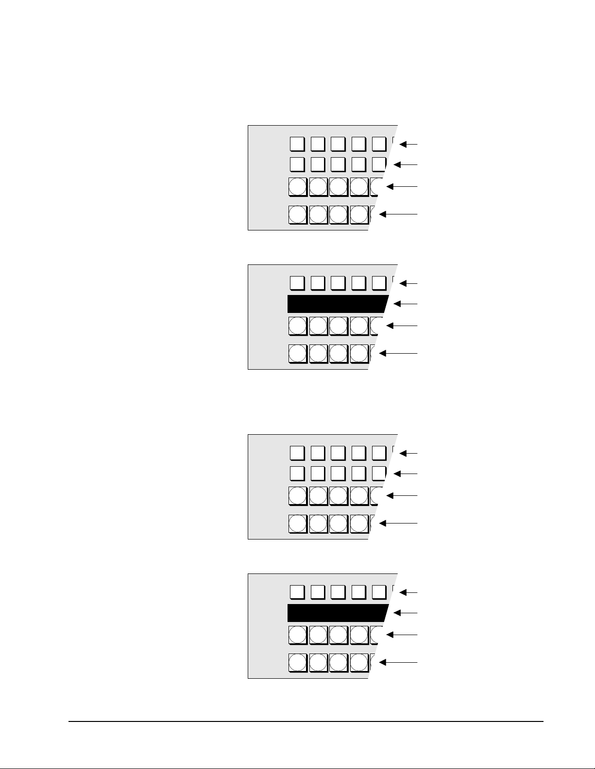
SONY
Front Control Panel components and sub-panels are listed (and illustrated) below:
1. Program/Preset Bus
• American Style (BKDS-7026)
PGM/PST
BLACK
DSK1
BLACK
DSK2
BLACK
A
BLACK
B
• Euro Style (BKDS-7025)
PGM/PST
BLACK
DSK
DSK Bus 1 crosspoints
DSK Bus 2 crosspoints
Program Bus crosspoints
Preset Bus crosspoints
DSK Bus crosspoints
BLK CAM1 CAM2 CAM3 CAM4
BLACK
A
BLACK
B
2. M/E (Mix/Effects) Banks 1 and 2
• American Style (BKDS-7026)
M/E 1
BLACK
K1
BLACK
K2
BLACK
A
BLACK
B
• Euro Style (BKDS-7025)
M/E 1
BLACK
K
Source Name Display
Program Bus crosspoints
Preset Bus crosspoints
M/E Keyer 1 crosspoints
M/E Keyer 2 crosspoints
M/E Bus "A" crosspoints
M/E Bus "B" crosspoints
M/E Keyer crosspoints
BLK CAM1 CAM2 CAM3 CAM4
BLACK
A
BLACK
B
Source Name Display
M/E Bus "A" crosspoints
M/E Bus "B" crosspoints
DVS-7250 • Product Guide Installation Guide •• 39
Page 48

SONY
3. Aux (Auxiliary) Bus Bank
AUX
BLACK
VTR1 VTR2 CAM2 CG1 DME1
AUX
AUX2AUX3AUX4AUX
1
CAM3 CAM4CAM1 CAM2 FM2
CG1 CG2 GFX1 GFX2 FM1VTR3 VTR4VTR1 VTR2
5
4. Transition Control Section
Key Status Indicators
Next Transition
Selection Buttons
Transition Type
Selection Buttons
Auto Transition
Control Section
BKGD
NEXT TRANSITION
MIX NAM
FRAMES
AUTO
TRANS
KEY1KEY2KEY
SUPER
MIX
DME1DME
TRANSITION TY PE
Source Name
Display
Aux Bus Delegation
buttons
Source Name
Display
Aux Bus crosspoints
Fader
PRIOR
WIPE
2
CUT
Transition
Indicator
5. Top Menu Section
KEY1KE Y
2
KEY1KE Y
2
KEY1KE Y
2
KEY
REGS DIS K M ISC SETU P DIAG
FRA ME
BK GD
FRE ZE
EDGE
RECU R
NO N-
GRAPH
LINEA R
TOP MENU
WIP E D ME
WIP E D ME
WIP E D ME
PG M/PST
SYSTEM
PIC
VIDEO
MO D
LIGH T
EFF
STA TS
UTILITY
M/E 1
M/E 2
FRA ME
MO DINOU T
DME
SETUP
CH R
KE Y
CH R
KE Y
ME M
DME
BK GD
TRANS
BK GD
TRANS
BK GD
TRANS
FRA ME
STA TS
ME M
1
2
40 •• Installation Guide DVS-7250 • Product Guide
Page 49

Item
Selection
Buttons
SONY
6. Menu Control Section
Menu Screen
1
2
3
4
5
Parameter Controls
KEY
PAD
KEY
PAD
KEY
PAD
KEY
PAD
SHIFT
Function Keys
7. Floppy Disk Drive
8. M/E Keyer Section
KEY CONTROL
KEY
KEY
MATTE
FILL
LUM
1
KEY
MIX
1 2 43
2
AUTO
SPLIT BORD
SEL
LIN
CLEAN CHR
KEY
ON
KEY 1 KEY 2
DROP
BORD
PTN
SHDW
KEY
INV
KEY
MIX
9. DME Control Panel (BKDS-7031)
PROC
KEY
ON
OUT
LINE
KEY
EXIT
F10F9F8F7F6F5F4F3F2F1
Cursor Keys
MENU SRCE TRGT
ASP
LOC
SIZE
AXIS
LOC
Y Z
CTR
LOC
XYZ
ROT
VELO
HOLD
SKEW
PERS
ORTH
X
CLR
WRK
BFR
DVS-7250 • Product Guide Installation Guide •• 41
Page 50

SONY
10. Key Frame Control Panel (BKDS-7030)
DEL
GO
TO
KF
KF
STOP
NEXT
KF
REV
RE
WIND
RUN
EDIT
EFF
ENBL
DURKFDUR
COPY PASTE DELAY
FROM
MOD
TO
GO
INS
TO
TC
PREVKFNEXT
SHIFT
11. Master E-File Section with Numeric Keypad
SNAP
DME
DME
DME
DME
EFF
1
2
3
4
SHOT
DME
GLBL
ALL
M/E
M/E
P/P
DSK
USER
TRANS
7 8 9
RATE
1
LASTX
STORE
LEARN
RCALL
4 5 6
1 2 3
0
2
TRANS
ENTER
12. Downstream Keyer Section (BKDS-7340)
EFF
DIS
CLR
AUTO
TRIM
XPT
DSBL
+/-
1 2
43
DSK1
1 2
43
DSK2
13. FlexiPad
DOWN STREAM KEYER
DSK
DSK
2
1
MATTE
AUTO
FILL
LUM
DSK
SPLIT BORD
SEL
LIN
CLEAN
DSK
MIX
ON
DSK 1 DSK 2
XPT
KEY
DSBL
DSBL
SHIFT
DME
WIPE
SNAP
SHOT
DROP
SHDW
BORD
KEY
PTN
INV
DSK
MIX
7 8 9
4 5 6
1 2 3
EFF
0
DISS
TRANS
AUTO
PROC
DSK
ON
OUT
LINE
KEY
FADE
TO
BLACK
42 •• Installation Guide DVS-7250 • Product Guide
Page 51

SONY
Control Panel Top View — Euro Style
The figure below illustrates a top view of the DVS-7250 Euro Style Control Panel
(BKDS-7025).
54
3
2
1
12
13
DVS-7250 Control Panel (Euro Style) Top View
1) Program/Preset Bus 6) Menu Control Section 11) Master E-File Section
2) M/E Banks 1 and 2 7) Floppy Disk Drive 12) Downstream Keyer Section
3) Aux Bus Bank 8) M/E Keyer Section 13) FlexiPad
4) Transition Control Section 9) DME Control Panel
5) Top Menu Section 10) Key Frame Control Panel
6 7
8
9
10
11
For illustrations of Euro Style switcher sections and sub panels, refer to the previous
“Control Panel Top View — American Style” section.
DVS-7250 • Product Guide Installation Guide •• 43
Page 52

SONY
Sub Panel Remote Installation with BKDS-7075
The figure below illustrates BKDS-7075 Remote Adaptor external dimensions and
cutout dimensions (in millimeters).
Hole for
Nylon Rivet
84
24
Side View
132
26 2-M4
55
Bottom View
212
Feet
Connectors
78.5
74
Slot for Joint Bracket
Cutout
Dimensions
Side View
Cable
Access
212
132
Note that the BKDS-7075 Control Panel Remote Adaptor can be used to install
switcher sub panels in both horizontal and vertical configurations. Two examples
are illustrated below, and larger arrays can be configured:
Horizontal Configuration Vertical Configuration
To accommodate the desired configuration, the BKDS-7075 remote adapter's
internal IF-629 board can be mounted in a variety of orientations. Refer to the
DVS-7000/7200 E1 Installation Guide for IF-629 board mounting instructions.
44 •• Installation Guide DVS-7250 • Product Guide
Page 53

SONY
Control Panel External Dimensions
The figure below illustrates external control panel dimensions and control panel
cutout dimensions (in millimeters). Note that the illustrations shows all control
panel options installed.
532
532
Side View
14.5
536
152
508
1290
Rear
View
1294
1265
216
11-M4
15
300 300 300 300 47
638 638
9
Control Console Cutout
Top View
Side View
186
82
15
DVS-7250 External Control Panel Dimensions
DVS-7250 • Product Guide Installation Guide •• 45
Page 54

SONY
Control Panel Specifications
The following table lists Control Panel specifications:
DVS-7250 Control Panel Specifications
Parameter Specification
Control Panel Dimensions mm:
inches:
EL Display Dimensions mm:
inches:
Cutout Dimensions (Outer) mm:
inches:
(Inner) mm:
inches:
Weight 40 kg
Operating temperature +5°C to +40°C
Power requirements AC 100 - 240V ± 10%, 50/60 Hz
Power consumption 7 to 3.5A
1290 (w) x 532 (h) x 152 (d)
50.79 (w) x 20.94 (h) x 5.98 (d)
499 (w) x 197 (h) x 45 (d)
19.65 (w) x 7.76 (h) x 1.77 (d)
1294 (w) x 536 (d)
50.94 (w) x 21.10 (d)
1265 (w) x 15 (h) x 508 (d)
49.80 (w) x 0.59 (h) x 20.00 (d)
88 lbs. 2 oz.
Connectors
GPI 25-pin D-sub connector, female
Option Panel 25-pin D-sub connector, female
Switcher 9-pin D-sub connector (RS-422A), female
DSK 9-pin D-sub connector (RS-422A), female
DME 9-pin D-sub connector (RS-422A), female
Terminal 1 9-pin D-sub connector (RS-232C), female
Terminal 2 9-pin D-sub connector (RS-232C), female
Remote 1 9-pin D-sub connector (RS-422A), female
Remote 2 9-pin D-sub connector (RS-422A), female
Remote 3 9-pin D-sub connector (RS-422A), female
Remote 4 9-pin D-sub connector (RS-422A), female
Remote 5 9-pin D-sub connector (RS-422A), female
AUX Panel 25-pin D-sub connector, female
Display Panel 25-pin D-sub connector, female
46 •• Installation Guide DVS-7250 • Product Guide
Page 55

SONY
Control Panel Rear View
The figure below illustrates a rear view of the DVS-7250 Control Panel.
1
GPI
OPTION PANEL
8
2
SWITCHER
REMOTE 1
9
3
DSK
REMOTE 2
10
4
DME
REMOTE 3
11
5
TERMINAL 1
REMOTE 4
12
6 7
TERMINAL 2
REMOTE 5
13
DVS-7250 Control Panel Rear View
Rear Control Panel components are listed below:
1. GPI (25-pin D-sub, female)
2. Switcher (9-pin D-sub, female) RS-422A
3. DSK (9-pin D-sub, female) RS-422A
4. DME (9-pin D-sub, female) RS-422A
5. Terminal 1 (9-pin D-sub, female) Wacom IV tablet or RS-232C
6. Terminal 2 (9-pin D-sub, female) Wacom IV tablet or RS-232C
7. AUX Panel (25-pin D-sub, female)
8. Option Panel (25-pin D-sub, female)
AUX PANEL
DISPLAY PANEL
14
AC IN
A
15 16 17
AC IN
B
9. Remote 1 (9-pin D-sub, female) RS-422A
10. Remote 2 (9-pin D-sub, female) RS-422A
11. Remote 3 (9-pin D-sub, female) RS-422A
12. Remote 4 (9-pin D-sub, female) RS-422A
13. Remote 5 (9-pin D-sub, female) RS-422A
14. Display Panel (25-pin D-sub, female)
15. AC In A, 3-pin AC connector (Main Power Supply)
16. Ground Terminal
17. AC In B, 3-pin AC connector (Optional Backup Power Supply)
DVS-7250 • Product Guide Installation Guide •• 47
Page 56

SONY
Control Panel Connectors
The following control panel connectors are listed in this section:
• Switcher
• DSK
• DME
• Terminal 1, 2
• Remote 1 - 5
• GPI (25-pin D-sub, female)
• Option Panel (25-pin D-sub, female)
• AUX Panel (25-pin D-sub, female)
• Display Panel (25-pin D-sub, female)
RS-422A Switcher Connector Specifications
The table below lists specifications for the control panel RS-422A Switcher
connector:
5 4 3 2 1
9 678
RS-422A Switcher Connector specifications (Female)
Pin # Signal Function
1 FG Frame Ground
2 RX-A Received data (–)
3 TX-B Transmitted data (+)
4 GND Common ground
5 Field (+) Field signal input (+)
6 GND Common ground
7 RX-B Received data (+)
8 TX-A Transmitted data (–)
9 Field (–) Field signal input (–)
Note that RS-422 interconnect cables are not provided. In the “Options and
Upgrades” section, see the “System Cables, RS-422” heading for part numbers
and information. RS-422 interconnect cables have a maximum length of 100
meters.
48 •• Installation Guide DVS-7250 • Product Guide
Page 57

SONY
RS-422A DSK Connector Specifications
The table below lists specifications for the control panel RS-422A DSK connector:
5 4 3 2 1
9 678
RS-422A DSK Connector Specifications (Female)
Pin # Signal Function
1 FG Frame Ground
2 RX-A Received data (–)
3 TX-B Transmitted data (+)
4 GND Common ground
5 — —
6 GND Common ground
7 RX-B Received data (+)
8 TX-A Transmitted data (–)
9 — —
RS-422A DME Connector Specifications
The table below lists specifications for the control panel RS-422A DME connector:
5 4 3 2 1
9 678
RS-422A DME Connector Specifications (Female)
Pin # Signal Function
1 FG Frame Ground
2 RX-A Received data (–)
3 TX-B Transmitted data (+)
4 GND Common ground
5 — NC
6 GND Common ground
7 RX-B Received data (+)
8 TX-A Transmitted data (–)
9 — —
DVS-7250 • Product Guide Installation Guide •• 49
Page 58

SONY
RS-232C Terminal 1, 2 Connector Specifications
The following table lists control panel RS-232C Terminal 1, 2 connector
specifications:
5 4 3 2 1
9 678
RS-232C Terminal 1, 2 Connector Specifications (Female)
Pin # Signal Function
1 DCD Received line detector signal *
2 RX Received data
3 TX Transmitted data
4 DTR Data terminal ready signal *
5 GND Signal ground
6 DSR Data set ready signal *
7 RTS Request to send signal **
8 CTS Clear to send signal **
9 — —
Note: * Pins 1, 4, and 6 are shorted together on the CN-1143 board.
** Pins 7 and 8 are shorted together on the CN-1143 board.
RS-422A Remote 1-5 Connector Specifications
The table below lists specifications for the control panel RS-422A Remote 1-5
connectors: *
5 4 3 2 1
9 678
RS-422A Remote 1 - 4 Connector Specifications (Female)
Pin # Signal Function
1 FG Frame Ground
2 RX-A Received data (–)
3 TX-B Transmitted data (+)
4 GND Common ground
5 — —
6 GND Common ground
7 RX-B Received data (+)
8 TX-A Transmitted data (–)
9 — —
Note: * Remote connectors 2, 3, 4, and 5 are active only if the
BKDS-7001 board is installed.
50 •• Installation Guide DVS-7250 • Product Guide
Page 59

GPI Connector Specifications
The following table lists control panel GPI connector specifications.
5 4 3 2 1
10 9111213
22 21232425
GPI Control Panel Connector Specifications (Female)
Pin # Signal Function
1 GND Ground
2 GND Ground
3 GPI In 2
4 GPI In 4 General purpose relay input
5 GPI In 6
6 GPI In 8
7 GPI Out 1B
8 GPI Out 2B General purpose relay output (B) *
9 GPI Out 3B
10 GPI Out 4B
11 GPI Out 6 General purpose open collector output **
12 GPI Out 8
13 GPI Out Com Ground
14 GND Ground
15 GPI In 1
16 GPI In 3 General purpose input
17 GPI In 5
18 GPI In 7
19 GPI Out 1A
20 GPI Out 2A General purpose relay output (A) *
21 GPI Out 3A
22 GPI Out 4A
23 GPI Out 5 General purpose open collector output **
24 GPI Out 7
25 GPI Out Com Ground
678
181920
14151617
SONY
Note: A and B of the same number constitute a pair of relay contacts.
(Relay)
*
GPI Out XB
GPI Out XA
X; 1-4
(Open
**
collector
output)
DVS-7250 • Product Guide Installation Guide •• 51
+V
GPI Out 5-8
GPI Out Com
Page 60

SONY
Option Panel Connector Specifications
The following table lists control panel Option Panel connector specifications.
5 4 3 2 1
10 9111213
22 21232425
Option Panel Connector Specifications (Female)
Pin # Signal Function
1 GND Ground
2 +12 V Power supply +12 V
3 SCLK Serial clock for switch read and LED light
4 GND Ground
5 WDT LED light data
6 IWLD Control signal for switch read and LED light
7 GND Ground
8 TCLK Serial clock for character display
9 TWDT Indicate data for character display
10 GND Ground
11 TBLANK Disable signal for character display
12 GND Ground
13 GND Ground
14 +12 V Power supply +12 V
15 +12 V Power supply +12 V
16 BLANK LED light disable signal
17 GND Ground
18 SEQ Control signal for switch read and LED light
19 RDT Switch read data
20 GND Ground
21 TSEQ Control signal for character display
22 TQCLK Control signal for character display
23 +12 V Power supply +12 V
24 +12 V Power supply +12 V
25 GND Ground
678
181920
14151617
52 •• Installation Guide DVS-7250 • Product Guide
Page 61

SONY
AUX Panel Connector Specifications
The following table lists control panel AUX Panel connector specifications.
5 4 3 2 1
10 9111213
22 21232425
AUX Panel Connector Specifications (Female)
Pin # Signal Function
1 GND Ground
2 +12 V Power supply +12 V
3 SCLK Serial clock for switch read and LED light
4 GND Ground
5 WDT LED light data
6 IWLD Control signal for switch read and LED light
7 GND Ground
8 TCLK Serial clock for character display
9 TWDT Indicate data for character display
10 GND Ground
11 TBLANK Disable signal for character display
12 GND Ground
13 GND Ground
14 +12 V Power supply +12 V
15 +12 V Power supply +12 V
16 BLANK LED light disable signal
17 GND Ground
18 SEQ Control signal for switch read and LED light
19 RDT Switch read data
20 GND Ground
21 TSEQ Control signal for character display
22 TQCLK Control signal for character display
23 +12 V Power supply +12 V
24 +12 V Power supply +12 V
25 GND Ground
678
181920
14151617
DVS-7250 • Product Guide Installation Guide •• 53
Page 62
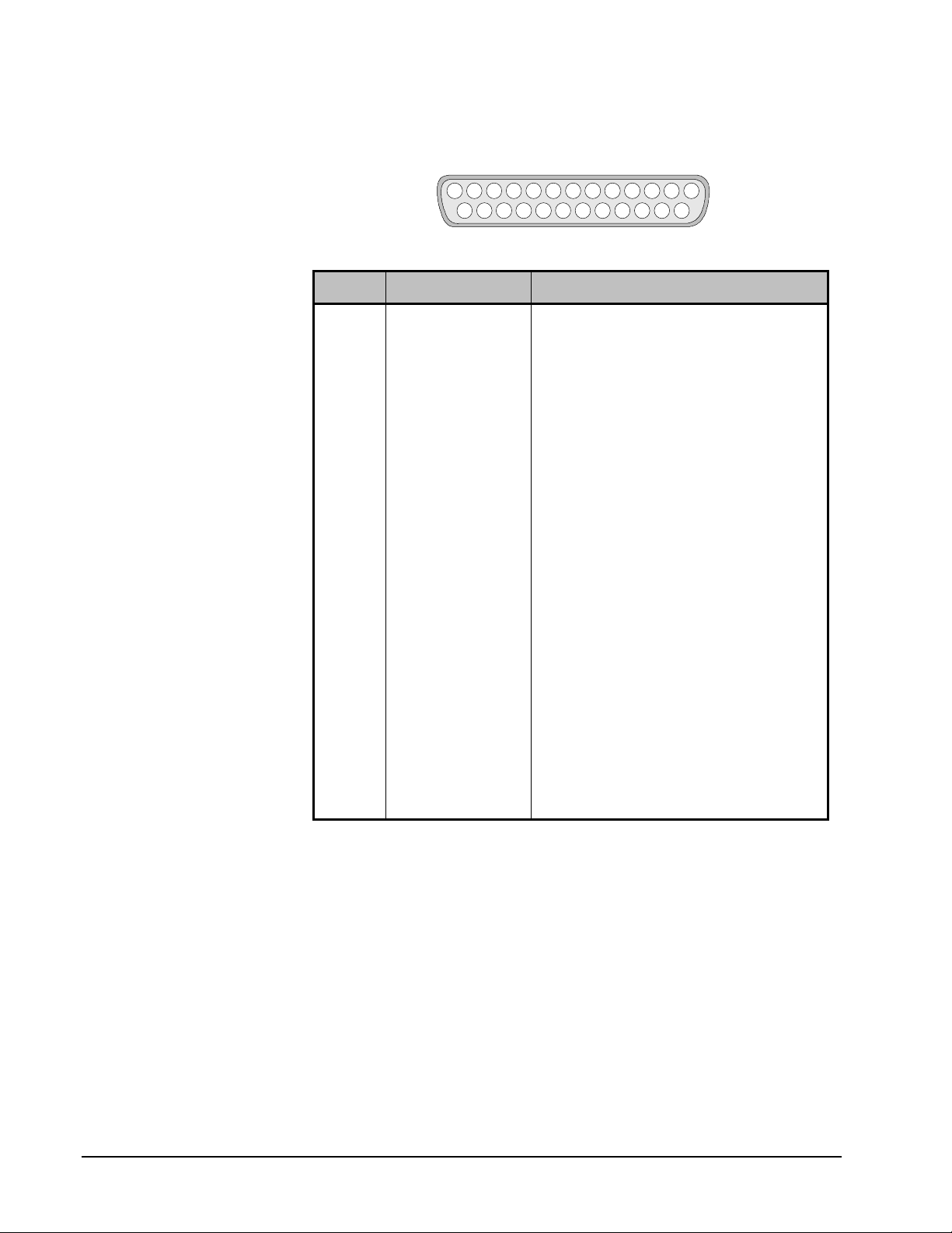
SONY
Display Panel Connector Specifications
The following table lists control panel Display Panel connector specifications.
5 4 3 2 1
10 9111213
22 21232425
Display Panel Connector Specifications (Female)
Pin # Signal Function
1 GND Ground
2 +12 V Power supply +12 V
3 SCLK Serial clock for switch read and LED light
4 GND Ground
5 WDT LED light data
6 IWLD Control signal for switch read and LED light
7 GND Ground
8 ELCK EL display indicate clock
9 EL DATA 0 EL display indicate data
10 GND Ground
11 ELVD EL display vertical sync signal
12 GND Ground
13 GND Ground
14 +12 V Power supply +12 V
15 +12 V Power supply +12 V
16 BLANK LED light disable signal
17 GND Ground
18 SEQ Control signal for switch read and LED light
19 RDT Switch read data
20 GND Ground
21 ELHD EL display horizontal sync signal
22 EL DATA 1 EL display indicate data 1
23 +12 V Power supply +12 V
24 +12 V Power supply +12 V
25 GND Ground
678
181920
14151617
54 •• Installation Guide DVS-7250 • Product Guide
Page 63

Additional Control Panels
This section discusses the following additional control panels that can be added to
the DVS-7250 system:
• BKDS-2010 — M/E Auxiliary Control Panel
• BKDS-7060 — Remote Key Control Panel
• BKDS-8060 — Remote Panel Interface
• BKDS-8061 — Shot Box Control Unit
• BKDS-8062 — Auxiliary Control Panel
SONY
DVS-7250 • Product Guide Installation Guide •• 55
Page 64

SONY
BKDS-2010 — M/E Auxiliary Control Panel
This section includes four areas:
• BKDS-2010 Control Panel Top View
• BKDS-2010 Control Panel Rear View
• BKDS-2010 Control Panel External Dimensions
• BKDS-2010 Control Panel Specifications
• BKDS-2010 Control Panel Connectors
BKDS-2010 Control Panel Top View
The figure below illustrates a top view of the BKDS-2010 Control Panel.
SONY
ENABLE
EDITOR DME GPI
SYSTEM
SETUP MEM MISC
USER MENU
1 2 3
MATTE KEY CONTROL
COLOR
2ND
MIX
MATTE
KEY
KEY
1
DSK
2
EDGE
KEY
KEY
1
DSK
2
FILL
SHIFT
BLACK
AUX BUSES
BLACK
KEY BUSES
BLACK
PGM BUS
BLACK
PST BUS
F1 F2 F3 F4 F5 F6
KEY
SELFMATTE AUTO SPLIT
BUS
FILL SOURCE
WIPE
BORD
TYPE
COLOR
BKGD
KEY
KEY
1
DSK
2
DELEGATION
FRAME
KEY
MEM
SRCE
CHRLINLUM CLEAN PTN
1
FRAME
MEM
WIPE
DIRECTION
NORM
NORM
MULTI
BORD SOFT ASPCT
EXIT
FINE
KEY
BORD
DROP
BORD
SHDW
OUT
LINE
AUTO
TRANS
EDGE
DEPTH
AUX
1
2
PROC
MAIN
KEY
MASK
KEY
AUX
AUX
3
2
COLOR
COLOR
SUB
MASK
MODIFY
21 3 4
UTILITY
EDIT
PVW
BKGD
BKGD
KEY
INV
LEARN
RECALL DIRECT ENTER
OVER OVER
KEY2
KEY1
KEY
PRIOR
BKGD
ON
KEY1KEY
ON
2
NEXT TRANSITION
COLOR
BKGD
MIX WIPE DME
TRANSITION TYPE
COLOR
BKGD
AUTO
TRANS
CUT
DSK
FTB
RATE
WIPE
ROTA-
REV
REV
MOD
TION
POS
ON
+/-
EFF
7
8 9
4 5 6
1 2 3
USER
DISS
CLEAR
AUTO
TRANS
TRIM
XPT
DSBL
0 .
FADE
TO
BLACK
DSK
PVW
DSK
DSK
MIX
CUT
BKDS-2010 Control Panel Top View
56 •• Installation Guide DVS-7250 • Product Guide
Page 65

BKDS-2010 Control Panel Rear View
The figure below illustrates a rear view of the BKDS-2010 Control Panel.
SWITCHER SPARE TERMINAL AC IN
1 2 3 4 5 6
BKDS-2010 Control Panel Rear View
SONY
Control Console Cutout
Top View
415
Rear Control Panel components are listed below:
1. Switcher (D-sub 9-pin) RS-422A
2. Spare (D-sub 9-pin) RS-422A. Not active.
3. Terminal (D-sub 9-pin) Wacom IV tablet or RS-232C
4. AC In, 3-pin AC connector
5. Ground terminal
6. Slot for optional Memory Pack
BKDS-2010 Control Panel External Dimensions
The figure below illustrates external BKDS-2010 dimensions (in millimeters):
more than 100
391
61.7
Side View
400
400
424
120
Top View
Rear View
BKDS-2010 External Control Panel Dimensions
DVS-7250 • Product Guide Installation Guide •• 57
Page 66

SONY
BKDS-2010 Control Panel Specifications
The following table lists BKDS-2010 Control Panel specifications:
BKDS-2010 Control Panel Specifications
Parameter Specification
Dimensions mm:
inches:
Cutout Dimensions mm:
inches:
Weight (approximate) 10.0 kg
Processor connector 9-pin D-sub connector (RS-422A)
Terminal connector 9-pin D-sub connector (RS-422A or RS-232C)
AC In 3-pin AC connector
Operating temperature +5° to +40°C
For operation within specifications +10° to +35°C
Power consumption Max. 0.5A/0.3A (100-120V/200-240V)
424 (w) x 120 (h) x 400 (d)
16.75 (w) x 4.75 (h) x 15.75 (d)
415 (w) x 391 (d)
16.34 (w) x 15.39 (d)
22 lb. 1 oz.
+41° to +104°F
50° to +95°F
BKDS-2010 Control Panel Connectors
The following BKDS-2010 control panel connectors are listed in this section:
• Switcher Connector
• Terminal Connector
The table below lists specifications for the BKDS-2010 control panel RS-422A
Switcher connector:
5 4 3 2 1
9 678
BKDS-2010 RS-422A Control Panel Switcher Connector Specifications (Female)
Pin # Signal Function
1 FG Frame Ground
2 RX-A Received data (–) from Processor
3 TX-B Transmitted data (+) to Processor
4 TX-COM Signal Ground
5 VD (+) VD signal input (+) from Processor
6 RX-COM Signal Ground
7 RX-B Received data (+) from Processor
8 TX-A Transmitted data (–) to Processor
9 VD (–) VD signal input (–) from Processor
58 •• Installation Guide DVS-7250 • Product Guide
Page 67

SONY
The table below lists specifications for the BKDS-2010 control panel RS-422A or RS232C Terminal connector:
5 4 3 2 1
9 678
BKDS-2010 RS-422A or RS-232C Control Panel Terminal Connector Specifications (Female)
Pin # Signal Function
1 DCD Received line signal detector signal
2 RX Received data
3 TX Transmitted data
4 DTR Data terminal ready signal
5 GND Signal ground
6 DSR Data set ready signal
7 RTS Request to send signal
8 CTS Clear to send signal
9 — —
DVS-7250 • Product Guide Installation Guide •• 59
Page 68

SONY
• BKDS-7060 Control Panel Top View • BKDS-7060 Power Supply Front View
• BKDS-7060 Control Panel External Dimensions• BKDS-7060 Power Supply External Dimensions
• BKDS-7060 Control Panel Specifications • BKDS-7060 Power Supply Specifications
• BKDS-7060 Control Panel Rear View • BKDS-7060 Power Supply Rear View
• BKDS-7060 Control Panel Connectors • BKDS-7060 Power Supply Connectors
BKDS-7060 — Remote Key Control Panel
This section includes the following areas:
BKDS-7060 Control Panel Top View
The figure below illustrates a top view of the BKDS-7060 Keyer Control Panel.
SONY
LAST
F1
MENU
BKDS-7060 Control Panel Top View
F2 F3 F4 F5 F6
KEYER REMOTE CONTROL PANEL
EXIT
HOME
BKDS-7060 Control Panel External Dimensions
The figure below illustrates external BKDS-7060 dimensions (in millimeters):
Top
View
132
132
Side View
64
BKDS-7060 External Control Panel Dimensions
325
Rear
View
60 •• Installation Guide DVS-7250 • Product Guide
Page 69

BKDS-7060 Control Panel Specifications
The following table lists BKDS-7060 Control Panel specifications:
BKDS-7060 Control Panel Specifications
Parameter Specification
SONY
Dimensions mm:
inches:
Weight (approximate) 1.2 kg
Pig Tail Connector 15-pin D-sub connector (RS-232C) Male
Operating environment +5°C to +40°C
Power consumption Supplied by BKDS-7060 Power Supply
325 (w) x 64 (h) x 132 (d)
12.80 (w) x 2.52 (h) x 5.20 (d)
2 lb. 11 oz.
BKDS-7060 Control Panel Rear View
The figure below illustrates a rear view of the BKDS-7060 Keyer Control Panel.
BKDS-7060 Control Panel Rear View
Rear Control Panel components are listed below:
1. Control Panel Connector (D-sub 15-pin male) RS-232C
1
CONTROL PANEL
DVS-7250 • Product Guide Installation Guide •• 61
Page 70

SONY
BKDS-7060 Control Panel Connectors
The table below lists specifications for the BKDS-7060 Control Panel RS-232C Pig
Tail Connector:
54321
6 7 8
9 10 11 12
BKDS-7060 Control Panel RS-232C Pig Tail Connector Specifications (Male)
Pin # Signal Function
1 TX0 Transmitted data 0
2 TX1 Transmitted data 1
3 TX2 Transmitted data 2
4 VD Transmitted VD signal
5 — —
6 — —
7 GND Ground
8 + 12V Power supply
9 RX0 Received data 0
10 RX1 Received data 1
11 RX2 Received data 2
12 GND Ground
13 — —
14 GND Ground
15 + 12V Power supply
13 14 15
SONY
BKDS-7060 Power Supply Front View
The figure below illustrates a front view of the Power Supply for the BKDS-7060.
21 3
POWER SUPPLY UNIT
TERMINAL
BKDS-7060 Power Supply Front View
Front Power Supply components are listed below:
1. Power Indicator
2. Terminal Connector (D-sub 9-pin female) RS-232C
3. Blank Panel for rack mounting
62 •• Installation Guide DVS-7250 • Product Guide
Page 71

SONY
BKDS-7060 Power Supply External Dimensions
The figure below illustrates external Power Supply dimensions (in millimeters):
120
120
Side
View
BKDS-7060 External Power Supply Dimensions
43.6
Top
View
212
Front
View
BKDS-7060 Power Supply Specifications
The following table lists BKDS-7060 Power Supply specifications:
BKDS-7060 Power Supply Specifications
Parameter Specification
Dimensions mm:
inches:
Weight (approximate) 1.2 kg
Terminal Connector (front panel) 9-pin D-sub connector (RS-232C) Female
Control Panel Connector (rear panel) 15-pin D-sub connector (RS-232C) Female
Control Out 1 Connector (rear panel) 9-pin D-sub connector (RS-422A) Female
Control Out 2 Connector (rear panel) 9-pin D-sub connector (RS-422A) Female
Operating environment +5°C to +40°C
Power requirements 100 to 240 V AC ± 10%, 50/60 Hz
Current consumption 0.4 A (max.)
212 (w) x 43.6 (h) x 120 (d)
8.35 (w) x 1.72 (h) x 4.72 (d)
2 lb. 11 oz.
DVS-7250 • Product Guide Installation Guide •• 63
Page 72
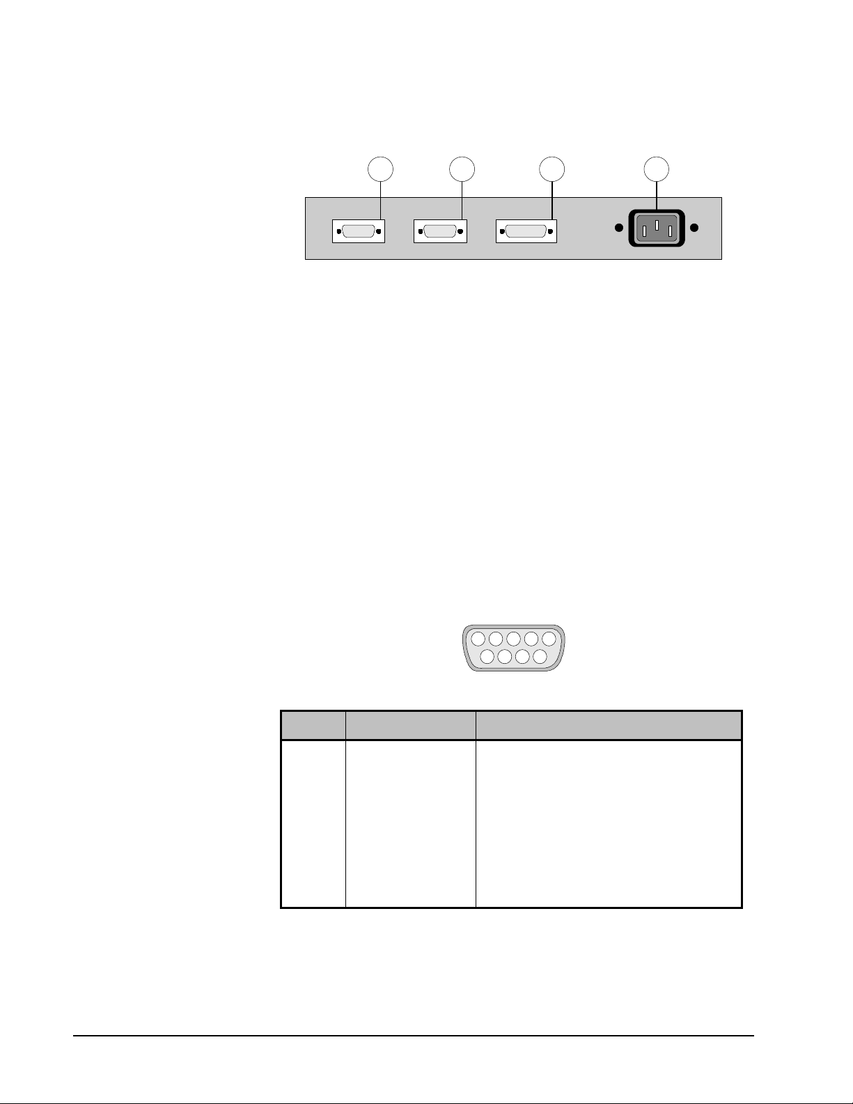
SONY
BKDS-7060 Power Supply Rear View
The figure below illustrates a rear view of the BKDS-7060 Power Supply.
1
CONTROL
OUT 2
234
CONTROL
OUT 1
BKDS-7060 Power Supply Rear View
CONTROL
PANEL
Rear Power Supply components are listed below:
1. AC Input
2. Control Panel Connector (D-sub 15-pin female) RS-232C
3. Control Out 1 Connector (D-sub 9-pin female) RS-422A
4. Control Out 2 Connector (D-sub 9-pin female) RS-422A
BKDS-7060 Power Supply Connectors
The following BKDS-7060 Power Supply connectors are listed in this section:
• Terminal Connector
• Control Panel Connector
• Control Out 1, 2 Connector
The table below lists specifications for the BKDS-7060 Power Supply RS-232C
Terminal connector:
5 4 3 2 1
9 678
BKDS-7060 Power Supply RS-232C Terminal Connector Specifications (Female)
Pin # Signal Function
1 DCD Data carrier detect
2 RXD Received data
3 TXD Transmitted data
4 DTR Data terminal ready
5 SG Signal ground
6 DSR Data set ready data
7 RTS Request to send data
8 CTS Clear to send data
9 — —
64 •• Installation Guide DVS-7250 • Product Guide
Page 73

SONY
The table below lists specifications for the BKDS-7060 Power Supply RS-232C
Control Panel connector:
5 4 3 2 1
678
131415
BKDS-7060 Power Supply RS-232C Control Panel Connector Specifications (Female)
Pin # Signal Function
1 RX0 Received data 0
2 RX1 Received data 1
3 RX2 Received data 2
4 VD Transmitted VD signal
5 — —
6 — —
7 GND Ground
8 + 12V Power supply
9 TX0 Transmitted data 0
10 TX1 Transmitted data 1
11 TX2 Transmitted data 2
12 GND Ground
13 — —
14 GND Ground
15 + 12V Power supply
9101112
The table below lists specifications for the BKDS-7060 Power Supply RS-422A
Control Out 1, 2 connectors:
5 4 3 2 1
9 678
BKDS-7060 Power Supply RS-422A Control Out 1, 2 Connector Specifications (Female)
Pin # Signal Function
1 FG Frame Ground
2 RX-A Received data (–)
3 TX-B Transmitted data (+)
4 GND Common ground
5 VD-B Received VD signal (+)
6 GND Common ground
7 RX-B Received data (+)
8 TX-A Transmitted data (–)
9 VD-A Received VD signal (–)
DVS-7250 • Product Guide Installation Guide •• 65
Page 74

SONY
BKDS-8060 — Remote Panel Interface
This section includes the following areas:
• BKDS-8060 Front View
• BKDS-8060 Rear View
• BKDS-8060 External Dimensions
• BKDS-8060 Specifications
• BKDS-8060 Connectors
BKDS-8060 Front View
The figure below illustrates a front view of the BKDS-8060 Remote Panel Interface.
1 432
SONY
REMOTE PANEL INTERFACE UNIT BKDS-8060
BKDS-8060 Remote Panel Interface Front View
TERMINAL
Front BKDS-8060 components are listed below:
1. Power Indicator.
2. Switch Cover (for access to DIP switches).
3. Terminal Connector (D-sub 9-pin female) RS-232C.
4. Blank Panel for rack mounting. Note that two BKDS-8060 units can
be rack-mounted together, side-by-side.
BKDS-8060 Rear View
The figure below illustrates a rear view of the BKDS-8060 Remote Panel Interface.
1
CONTROL
IN
CONTROL
OUT
234
PANEL
BKDS-8060 Remote Panel Interface Rear View
Rear BKDS-8060 components are listed below:
1. AC Input
2. Panel Connector (D-sub 15-pin female)
3. Control Out Connector (D-sub 9-pin female)
4. Control In Connector (D-sub 9-pin female)
66 •• Installation Guide DVS-7250 • Product Guide
Page 75

SONY
BKDS-8060 External Dimensions
The figure below illustrates external Remote Panel dimensions (in millimeters):
120
120
Side
View
BKDS-8060 External Remote Panel Interface Dimensions
43.6
Front
View
Top
View
212
BKDS-8060 Specifications
The following table lists BKDS-8060 Remote Panel Interface specifications:
BKDS-8060 Remote Panel Interface Specifications
Parameter Specification
Dimensions mm:
inches:
Weight (approximate) 1.2 kg
Terminal Connector (front panel) 9-pin D-sub connector (RS-232C) Female
Panel Connector (rear panel) 15-pin D-sub connector (Control) Female
Control In Connector (rear panel) 9-pin D-sub connector (RS-422A) Female
Control Out Connector (rear panel) 9-pin D-sub connector (RS-422A) Female
Operating temperature +5°C to +40°C
Storage temperature -20°C to +70°C
Humidity 10% to 90%
Power requirements 100 to 240 V AC ± 10%, 50/60 Hz
Current consumption 5 W (max.)
212 (w) x 43.6 (h) x 120 (d)
8.35 (w) x 1.72 (h) x 4.72 (d)
2 lb. 11 oz.
DVS-7250 • Product Guide Installation Guide •• 67
Page 76

SONY
BKDS-8060 Connectors
The following BKDS-8060 Remote Panel Interface connectors are listed:
• Terminal Connector • Control In Connector
• Panel Connector • Control Out Connector
The table below lists specifications for the BKDS-8060 RS-232C Terminal
connector:
5 4 3 2 1
9 678
BKDS-8060 Remote Panel Interface Terminal Connector Specifications (Female)
Pin # Signal Function
1 NC No connection
2 TXD Transmit data
3 RXD Request to send signal
4 NC No connection
5 GND Signal ground
6 NC No connection
7 CTS Clear to send signal
8 RTS Receive data
9 NC No connection
The table below lists specifications for the BKDS-8060 Panel control connector:
5 4 3 2 1
678
131415
BKDS-8060 Remote Panel Interface Panel Connector Specifications (Female)
9101112
Pin # Signal Function
1 L; SCLK Clock (negative logic)
2 GND Signal ground
3 L; LOAD Data latch signal (negative logic)
4 GND Signal ground
5 L; RST Reset signal (negative logic)
6 GND Signal ground
7 +5 V +5 V Power supply
8 +5 V +5 V Power supply
9 L; LED LED data (negative logic)
10 GND Signal ground
11 L; SW SW data (negative logic)
12 GND Signal ground
13 GND Signal ground
14 +5 V (LED) +5 V Power supply (for LED lighting)
15 +5 V (LED) +5 V Power supply (for LED lighting)
68 •• Installation Guide DVS-7250 • Product Guide
Page 77

SONY
The table below lists specifications for the BKDS-8060 RS-422A Control In
connector (controlled device):
5 4 3 2 1
9 678
BKDS-8060 Remote Panel Interface Control In Connector Specifications (Female)
Pin # Signal Function
1 GND Signal ground
2 TX0 (–) Transmit data (–) to switcher
3 RX0 (+) Receive data (+) from switcher
4 GND Signal ground
5 NC No connection
6 GND Signal ground
7 TX0 (+) Transmit data (+) to switcher
8 RX0 (–) Receive data (–) from switcher
9 GND Signal ground
The table below lists specifications for the BKDS-8060 RS-422A Control Out
connector (controlling device):
5 4 3 2 1
9 678
BKDS-8060 Remote Panel Interface Control Out Connector Specifications (Female)
Pin # Signal Function
1 GND Signal ground
2 RX1 (–) Receive data (–) from cascade connecting unit
3 TX1 (+) Transmit data (+) to cascade connecting unit
4 GND Signal ground
5 NC No connection
6 GND Signal ground
7 RX1 (+) Receive data (+) from cascade connecting unit
8 TX1 (–) Transmit data (–) to cascade connecting unit
9 GND Signal ground
DVS-7250 • Product Guide Installation Guide •• 69
Page 78

SONY
BKDS-8061 — Shot Box Control Unit
This section includes the following areas:
• BKDS-8061 Front View
• BKDS-8061 Rear View
• BKDS-8061 External Dimensions
• BKDS-8061 Specifications
• BKDS-8061 Connectors
BKDS-8061 Front View
The figure below illustrates a front view of the BKDS-8061 Shot Box Control Unit.
1
SO NY
1 2 3 4 5 6 7 8 9 10
1 2 3 4 5 6 7 8 9 10
MEMORY RECALL REMOTE PANEL BKDS-8061
BKDS-8061 Shot Box Control Unit Front View
Front BKDS-8061 components are listed below:
1. Memory recall buttons
2. Blank Panel for rack mounting. Note that two BKDS-8061 units can
be rack-mounted together, side-by-side.
BKDS-8061 Rear View
The figure below illustrates a rear view of the BKDS-8061 Shot Box Control Unit.
CASCADE
OUT
2
CASCADE
IN
1
2
BKDS-8061 Shot Box Control Unit Rear View
Rear BKDS-8061 components are listed below:
1. Cascade In Connector (D-sub 15-pin male)
2. Cascade Out Connector (D-sub 15-pin female)
70 •• Installation Guide DVS-7250 • Product Guide
Page 79

SONY
BKDS-8061 External Dimensions
The figure below shows external Shot Box Control Unit dimensions (in
millimeters):
47.5
47.5
Side
43.6
View
BKDS-8061 External Shot Box Control Unit Dimensions
Top
View
212
BKDS-8061 Specifications
The following table lists BKDS-8061 Shot Box Control Unit specifications:
BKDS-8061 Shot Box Control Unit Specifications
Parameter Specification
Dimensions mm:
inches:
Weight (approximate) 0.6 kg
Cascade In Connector 15-pin D-sub connector (Control) Male
Cascade Out Connector 15-pin D-sub connector (Control) Female
Operating temperature +5°C to +40°C
Storage temperature -20°C to +70°C
Humidity 10% to 90%
Power requirements Supplied by BKDS-8060
212 (w) x 43.6 (h) x 47.5 (d)
8.35 (w) x 1.72 (h) x 1.87 (d)
1 lb. 5 oz.
DVS-7250 • Product Guide Installation Guide •• 71
Page 80

SONY
BKDS-8061 Connectors
The following BKDS-8061 Shot Box Control Unit connectors are listed:
• Cascade In Connector
• Cascade Out Connector
The table below lists specifications for the BKDS-8061 Shot Box Cascade In and
Cascade Out control connectors. Pinouts are identical.
54321
6 7 8
9 10 11 12
Cascade In — Male
678
Cascade Out — Female
BKDS-8061 Shot Box Control Unit Cascade In, Out Connector Specifications
13 14 15
5 4 3 2 1
131415
9101112
Pin # Signal Function
1 L; SCLK Clock (negative logic)
2 GND Signal ground
3 L; LOAD Data latch signal (negative logic)
4 GND Signal ground
5 L; RST Reset signal (negative logic)
6 GND Signal ground
7 +5 V +5 V Power supply
8 +5 V +5 V Power supply
9 L; LED LED data (negative logic)
10 GND Signal ground
11 L; SW SW data (negative logic)
12 GND Signal ground
13 GND Signal ground
14 +5 V (LED) +5 V Power supply (for LED lighting)
15 +5 V (LED) +5 V Power supply (for LED lighting)
72 •• Installation Guide DVS-7250 • Product Guide
Page 81

SONY
BKDS-8062 — Auxiliary Control Panel
This section includes the following areas:
• BKDS-8062 Front View
• BKDS-8062 Rear View
• BKDS-8062 External Dimensions
• BKDS-8062 Specifications
• BKDS-8062 Connectors
BKDS-8062 Front View
The figure below illustrates a front view of the BKDS-8062 Auxiliary Control Unit.
1
SO NY
CASCADE
OUT
AUX BUS REMOTE PANEL BKDS-8062
BKDS-8062 Auxiliary Control Unit Front View
Front BKDS-8062 components are listed below:
1. Auxiliary Bus Crosspoints
BKDS-8062 Rear View
The figure below illustrates a rear view of the BKDS-8062 Auxiliary Control Unit.
CASCADE
IN
1
2
BKDS-8062 Auxiliary Control Unit Rear View
Rear BKDS-8062 components are listed below:
1. Cascade In Connector (D-sub 15-pin male)
2. Cascade Out Connector (D-sub 15-pin female)
DVS-7250 • Product Guide Installation Guide •• 73
Page 82

SONY
BKDS-8062 External Dimensions
The figure below shows external Auxiliary Control Unit dimensions (in
millimeters):
Top
View
424
47.5
Side
View
47.5
43.6
BKDS-8062 External Auxiliary Control Unit Dimensions
BKDS-8062 Specifications
The following table lists BKDS-8062 Auxiliary Control Unit specifications:
BKDS-8062 Auxiliary Control Unit Specifications
Parameter Specification
Dimensions mm:
inches:
Weight (approximate) 1.0 kg
Cascade In Connector 15-pin D-sub connector (Control) Male
Cascade Out Connector 15-pin D-sub connector (Control) Female
Operating temperature +5°C to +40°C
Storage temperature -20°C to +70°C
Humidity 10% to 90%
Power requirements Supplied by BKDS-8060
424 (w) x 43.6 (h) x 47.5 (d)
16.69 (w) x 1.72 (h) x 1.87 (d)
2 lb. 3 oz.
74 •• Installation Guide DVS-7250 • Product Guide
Page 83

SONY
BKDS-8062 Connectors
The following BKDS-8062 Auxiliary Control Unit connectors are listed:
• Cascade In Connector
• Cascade Out Connector
The table below lists specifications for the BKDS-8062 Auxiliary Control Unit
Cascade In and Cascade Out control connectors. Pinouts are identical.
54321
6 7 8
9 10 11 12
Cascade In — Male
678
Cascade Out — Female
BKDS-8062 Auxiliary Control Unit Cascade In, Out Connector Specifications
13 14 15
5 4 3 2 1
131415
9101112
Pin # Signal Function
1 L; SCLK Clock (negative logic)
2 GND Signal ground
3 L; LOAD Data latch signal (negative logic)
4 GND Signal ground
5 L; RST Reset signal (negative logic)
6 GND Signal ground
7 +5 V +5 V Power supply
8 +5 V +5 V Power supply
9 L; LED LED data (negative logic)
10 GND Signal ground
11 L; SW SW data (negative logic)
12 GND Signal ground
13 GND Signal ground
14 +5 V (LED) +5 V Power supply (for LED lighting)
15 +5 V (LED) +5 V Power supply (for LED lighting)
DVS-7250 • Product Guide Installation Guide •• 75
Page 84

SONY
DVS-7200 Chassis
This section includes the following areas:
Chassis Front View
The figure below illustrates a front view of the DVS-7200 chassis.
2
1 43
• Chassis Front View
• Chassis Rear View
• Chassis External Dimensions
• Chassis Specifications
• System Timing Requirements
• Chassis Connectors
SONY
DIGITAL VIDEO SWITCHER DVS-7200
DVS-7200 Chassis — Front View
Front chassis components are listed below:
1. Power Switch (Supply 1) 3. Power Switch (Supply 2, Backup)
2. Power Indicator (Supply 1) 4. Power Indicator (Supply 2, Backup)
76 •• Installation Guide DVS-7250 • Product Guide
Page 85
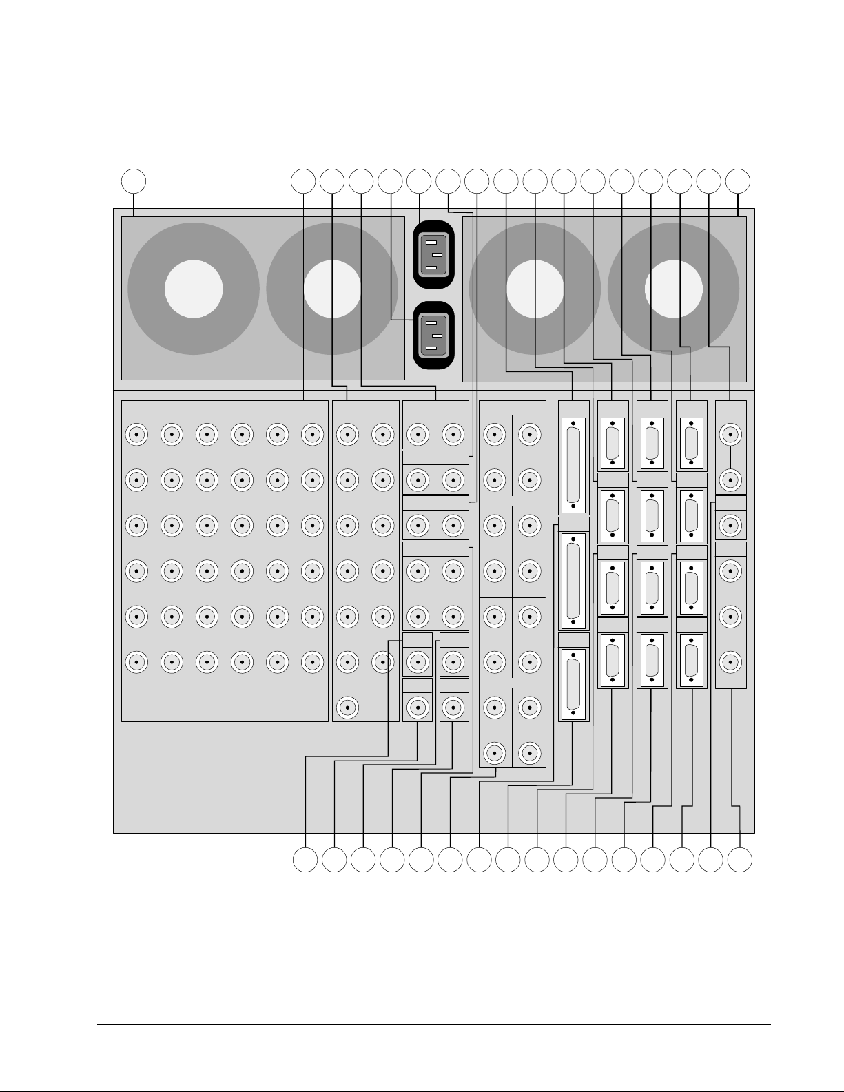
Chassis Rear View
The figure below illustrates a rear view of the DVS-7200 chassis.
SONY
3
AC IN
AC IN
AUX BUS
OUTPUTS
1
7
1
2
8
2
3
9
3
4
10
4
31
25
32
26
33
27
34
28
19
20
21
22
INPUTS
13
7
14
8
15
9
16
10
M/E 1
OUTPUTS
M/E 2
OUTPUTS
PROGRAM
OUTPUTS
3 1
9 20 2221 125 10242319245 6 7 8
B-Y/B
R-Y/R
SYNC
CRK INPUT/
D1 PRIMARY
Y/G
Y/G
B-Y/B
R-Y/R
SYNC
TERMINAL
GPI
CH 1CH 3
EXT
MATRIX
SERIAL
PANEL 1
TALLY
DSK DME 2 DME 1
DME 4 DME 3
REF
INPUTS
REF
OUTPUT
MONITOR
OUTPUT
1
Y/G
35
29
23
17
11
5
11
5
CLEAN
OUTPUT
EDIT PVW
OUTPUT
OUTPUT
DIRECT
INPUT
36
30
24
18
12
6
12
6
13
14131211
PVW
24
B-Y/B B-Y/B
R-Y/R R-Y/R
SYNC SYNC
Y/G Y/G
2
EDITOR A/
EDITOR B/
PANEL 2/
REMOTE 3
NETWORK
CH 2CH 4
REMOTE 2
REMOTE 1
B-Y/B
3
R-Y/R
181733323130292827261615
DVS-7200 Chassis — Rear View
Rear chassis components are listed below:
1. Cooling Fans (Supply 1)
2. AC In (Supply 1)
DVS-7250 • Product Guide Installation Guide •• 77
Page 86

SONY
3. Cooling Fans (Supply 2, Backup)
4. AC In (Supply 2, Backup)
5. Primary Inputs (1 - 36)
6. Auxiliary Bus Outputs (1 - 13)
7. M/E 1 Outputs (2, identical)
8. M/E 2 Outputs (2, identical)
9. Not active
10. Reference Video Input, Reference Loop
11. Clean Output
12. Edit Preview / Auxiliary Bus 14 Output
13. Preview Output
14. Direct Input
15. Program Outputs (4, identical)
16. Chroma Key Inputs (1 - 4), D1 Primary Inputs
17. Reference Video Output
18. Monitor Output. Not Active.
19. GPI (25-pin D-sub, female)
20. DSK (9-pin D-sub, female) RS-422A
21. Terminal (9-pin D-sub, female) RS-232C
22. DME 2 (9-pin D-sub, female) RS-422A
23. Serial Tally (9-pin D-sub, female) RS-422A
24. DME 1 (9-pin D-sub, female) RS-422A
25. Panel 1 (9-pin D-sub, female) RS-422A
26. EXT (25-pin D-sub, female). Not Active.
27. Network (15-pin D-sub, female). Not Active.
28. Matrix (9-pin D-sub, female) RS-422A
29. Panel 2 / Remote 3 (9-pin D-sub, female) RS-422A
30. DME 4 (9-pin D-sub, female) RS-422A
31. Editor B / Remote 2 (9-pin D-sub, female) RS-422A
32. DME 3 (9-pin D-sub, female) RS-422A
33. Editor A / Remote 1 (9-pin D-sub, female) RS-422A
78 •• Installation Guide DVS-7250 • Product Guide
Page 87

SONY
Chassis External Dimensions
The figure below illustrates external chassis dimensions (in millimeters):
450
Side View
DVS-7250 External Chassis Dimensions
443
Chassis Specifications
The following table lists chassis specifications:
Top View
424
DVS-7200 Chassis Specifications
Parameter Specification
Dimensions mm:
inches:
Weight 56 kg
Operating temperature +5°C to +40°C
Power requirement AC 100 - 240V ± 10%, 50/60 Hz
Power consumption 7 to 3.5A
Connectors
Primary Inputs
Signal level:
Return loss:
Chroma Key Inputs
Signal type:
Signal level:
DVS-7250 • Product Guide Installation Guide •• 79
424 (w) x 443 (h) x 450 (d)
16.69 (w) x 17.44 (h) x 17.72 (d)
123 lbs. 7 oz.
Serial digital video, BNC (x36), 75 ohms. Conforms to the
SMPTE specification PN-259M.
800 mV ±10%
15 dB min. (5 - 270 MHz)
Analog component video signal input, BNC (x16)
Y/B-Y/R-Y 9 (Betacam, SMPTE) / sync or G/B/R/sync
0 ±3 dB
Page 88

SONY
DVS-7200 Chassis Specifications (continued)
Parameter Specification
Connectors (continued)
Direct Input
With BKDS-7162 for EDIT PVW output
Signal level:
With BKDS-7161 for EDIT PVW output
Signal level:
Auxiliary Bus Outputs
With BKDS-7162
Signal level:
Transmission rate:
With BKDS-7161
Signal level:
Program Outputs
With BKDS-7162
Signal level:
Transmission rate:
With BKDS-7161
Signal level:
M/E 1, M/E 2 Outputs
With BKDS-7162
Signal level:
Transmission rate:
With BKDS-7161
Signal level:
Reference Video Input, Loop
Signal level:
SCH phase:
Reference Video Output
Signal level - Sync:
Burst:
SCH phase:
Signal level:
Clean Output
With BKDS-7162
Signal level:
Transmission rate:
With BKDS-7161
Signal level:
Edit Preview Output
With BKDS-7162
Signal level:
Transmission rate:
With BKDS-7161
Signal level:
Preview Output
With BKDS-7162
Signal level:
Transmission rate:
With BKDS-7161
Signal level:
GPI 25-pin D-sub, female
DSK 9-pin D-sub, female, RS-422A
Configurable, analog composite or digital
Serial digital video signal output, BNC (x1), 75 ohms
800 mV ±10%
Analog composite video signal output, BNC (x1), 75 ohms
0 ±3 dB
Configurable, analog composite or digital
Serial digital video signal output, BNC (x13), 75 ohms
800 mV ±10%
270 Mbps (component)/143 Mbps (composite)
Analog composite video signal output, BNC (x13), 75 ohms
1 Vp-p ±5%
Configurable, analog composite or digital
Serial digital video signal output, BNC (x4), 75 ohms
800 mV ±10%
270 Mbps (component)/143 Mbps (composite)
Analog composite video signal output, BNC (x4), 75 ohms
1 Vp-p ±5%
Configurable, analog composite or digital
Serial digital video signal output, BNC (x2), 75 ohms
800 mV ±10%
270 Mbps (component)/143 Mbps (composite)
Analog composite video signal output, BNC (x2), 75 ohms
1 Vp-p ±5%
Analog black burst or analog sync signal input, BNC (x2), 75
ohms, with loop-through.
0 ± 3 dB
0° ± 30°
Analog black burst signal output, BNC (x1), 75 ohms.
285 mVp-p ±14 mV
285 mVp-p ±14 mV
0° ± 30°
Analog sync signal output, BNC (x1), 75 ohms.
2 V ±0.5 V
Configurable, analog composite or digital
Serial digital video signal output, BNC (x1), 75 ohms
800 mV ±10%
270 Mbps (component)/143 Mbps (composite)
Analog composite video signal output, BNC (x1), 75 ohms
1 Vp-p ±5%
Configurable, analog composite or digital
Serial digital video signal output, BNC (x1), 75 ohms
800 mV ±10%
270 Mbps (component)/143 Mbps (composite)
Analog composite video signal output, BNC (x1), 75 ohms
1 Vp-p ±5%
Configurable, analog composite or digital
Serial digital video signal output, BNC (x1), 75 ohms
800 mV ±10%
270 Mbps (component)/143 Mbps (composite)
Analog composite video signal output, BNC (x1), 75 ohms
1 Vp-p ±5%
80 •• Installation Guide DVS-7250 • Product Guide
Page 89

DVS-7200 Chassis Specifications (continued)
Parameter Specification
Connectors (continued)
Matrix 9-pin D-sub, female, RS-422A
Terminal 9-pin D-sub, female, RS-232C
Serial Tally 9-pin D-sub, female, RS-422A
DME 1 9-pin D-sub, female, RS-422A
DME 2 9-pin D-sub, female, RS-422A
DME 3 9-pin D-sub, female, RS-422A
DME 4 9-pin D-sub, female, RS-422A
Panel 1 9-pin D-sub, female, RS-422A
Panel 2 / Remote 3 9-pin D-sub, female, RS-422A
Editor A / Remote 1 9-pin D-sub, female, RS-422A
Editor B / Remote 2 9-pin D-sub, female, RS-422A
Adjustable Parameters
Key Edge Left / Right Key Edges: ± 2 clock pulses
V-Proc Video Gain:
Luminance Gain:
Chrominance Gain:
Black Level:
Analog Composite Video Characteristics
-200 to +200 IRE (4:2:2 / 4fsc)
-200 to +200 IRE (4:2:2)
-200 to +200 IRE (4:2:2)
-7.31 to +109.64 IRE (4:2:2)
-42.86 to +140.00 IRE (4fsc)
Hue:
-180 degrees to + 180 degrees (4:2:2)
SONY
Dynamic Phase < 1°
Dynamic Gain < 1.5 %
Sampling Frequency 14.32 MHz
Frequency Response ± .5 dB (5 Hz to 5 MHz)
K Factor < 1 %
SN Ratio -55 dB minimum
Quantization 10-bit
DVS-7250 • Product Guide Installation Guide •• 81
Page 90

SONY
System Timing Requirements
The chart below shows input and output timing for the DVS-7250.
-0.5H
-0.4H +0.4H
REF
0H +0.5H +1.0H +1.5H +2.0H
INPUT
Window
-127CK +128CK
Input Phase
-30µSec +90µSec
OUTPUT
DVS-7250 System Phase Timing Chart
Please note the following important points:
• Values apply to input video, input key, and external input signals.
• Switcher video outputs are delayed by 1H to the reference signal. Note
that 1H = one horizontal line. One horizontal line = 63.5 µSec.
• Reference video output phase control is provided in the setup menu
within a range of -30 µSec to +90 µSec from input video reference.
Reference
Video Output
• The input video signals can be automatically corrected for a range of
±0.4H relative to input video reference.
• Fine adjustment is possible for independent input channels from 127 clocks to +128 clocks relative to input video reference. Note
that one clock = 74 nSec.
82 •• Installation Guide DVS-7250 • Product Guide
Page 91

Chassis Connectors
The following chassis connectors are listed in this section:
• DSK
• Terminal
• Serial Tally
• Matrix
• DME 1 - 4
• Panel 1
• Panel 2 / Remote 3
• Editor A / Remote 1
• Editor B / Remote 2
• GPI
RS-422A DSK Connector Specifications
The following table lists DVS-7200 Chassis RS-422A DSK connector
specifications:
SONY
5 4 3 2 1
9 678
RS-422A DSK Connector Specifications (Female)
Pin # Signal Function
1 FG Frame Ground
2 DSK TX-A Transmitted data (–)
3 DSK RX-B Received data (+)
4 GND Common ground
5 — —
6 GND Common ground
7 DSK TX-B Transmitted data (+)
8 DSK RX-A Received data (–)
9 FG Frame Ground
DVS-7250 • Product Guide Installation Guide •• 83
Page 92

SONY
RS-232C Terminal Connector Specifications
The following table lists DVS-7200 Chassis RS-232C Terminal connector
specifications:
5 4 3 2 1
9 678
RS-232C Terminal Connector Specifications (Female)
Pin # Signal Function
1 DCD Data Carrier detect *
2 RXD Received data
3 TXD Transmitted data
4 DTR Data terminal ready *
5 SG Signal ground
6 DSR Data set ready *
7 RTS Request to send
8 CTS Clear to send
9 — —
Note: * Pins 1, 4, and 6 are shorted together on the CN-1146 board.
RS-422A Serial Tally Connector Specifications
The following table lists DVS-7200 Chassis RS-422A Serial Tally connector
specifications:
5 4 3 2 1
9 678
RS-422A Serial Tally Connector Specifications (Female)
Pin # Signal Function
1 FG Frame ground
2 Serial Tally RX-A Received data (–)
3 Serial Tally TX-B Transmitted data (+)
4 GND Common ground
5 — —
6 GND Common ground
7 Serial Tally RX-B Received data (+)
8 Serial Tally TX-A Transmitted data (–)
9 FG Frame ground
84 •• Installation Guide DVS-7250 • Product Guide
Page 93

SONY
RS-422A Matrix Connector Specifications
The following table lists DVS-7200 Chassis RS-422A Matrix connector
specifications:
5 4 3 2 1
9 678
RS-422A Matrix Connector Specifications (Female)
Pin # Signal Function
1 FG Frame Ground
2 MTX TX-A Received data (–)
3 MTX RX-B Transmitted data (+)
4 GND Common ground
5 — —
6 GND Common ground
7 MTX TX-B Received data (+)
8 MTX RX-A Transmitted data (–)
9 FG Frame Ground
RS-422A DME Connector Specifications
The following table lists specifications for the DVS-7200 Chassis RS-422A DME
connectors 1 - 4:
5 4 3 2 1
9 678
RS-422A DME Connectors (1 - 4) Specifications (Female)
Pin # Signal Function
1 FG Frame Ground
2 DME 1 - 4 TX-A Transmitted data (–)
3 DME 1 - 4 RX-B Received data (+)
4 GND Common ground
5 — —
6 GND Common ground
7 DME 1 - 4 TX-B Transmitted data (+)
8 DME 1 - 4 RX-A Received data (–)
9 FG Frame Ground
DVS-7250 • Product Guide Installation Guide •• 85
Page 94

SONY
RS-422A Panel 1 Connector Specifications
The following table lists specifications for the DVS-7200 Chassis RS-422A Panel
1 connector:
5 4 3 2 1
9 678
RS-422A Panel 1 Connector Specifications (Female)
Pin # Signal Function
1 GND Frame Ground
2 CON TX-A Transmitted data (–)
3 CON RX-B Received data (+)
4 GND Common ground
5 VD-B Transmitted VD signal (+)
6 GND Common ground
7 CON TX-B Transmitted data (+)
8 CON RX-A Received data (–)
9 VD-A Transmitted VD signal (–)
RS-422A Panel 2/Remote 3 Connector Specifications
The following table lists DVS-7200 Chassis RS-422A Panel 2/Remote 3
connector specifications:
5 4 3 2 1
9 678
RS-422A Panel 2/Remote 3 Connector Specifications (Female)
Pin # Signal Function
1 GND Frame Ground
2 CON TX-A Transmitted data (–)
3 CON RX-B Received data (+)
4 GND Common ground
5 VD-B Transmitted VD signal (+)
6 GND Common ground
7 CON TX-B Transmitted data (+)
8 CON RX-A Received data (–)
9 VD-A Transmitted VD signal (–)
86 •• Installation Guide DVS-7250 • Product Guide
Page 95

SONY
RS-422A Editor A/Remote 1 Connector Specifications
The table below lists specifications for the DVS-7200 Chassis RS-422A Editor
A/Remote 1 connector:
5 4 3 2 1
9 678
RS-422A Editor A/Remote 1 Connector Specifications (Female)
Pin # Signal Function
1 FG Frame Ground
2 Edit A TX-A Transmitted data (–)
3 Edit A RX-B Received data (+)
4 GND Common ground
5 — —
6 GND Common ground
7 Edit A TX-B Transmitted data (+)
8 Edit A RX-A Received data (–)
9 FG Frame Ground
RS-422A Editor B/Remote 2 Connector Specifications
The table below lists specifications for the DVS-7200 Chassis RS-422A Editor
B/Remote 2 connector:
5 4 3 2 1
9 678
RS-422A Editor B/Remote 2 Connector Specifications (Female)
Pin # Signal Function
1 FG Frame Ground
2 Edit B TX-A Transmitted data (–)
3 Edit B RX-B Received data (+)
4 GND Common ground
5 — —
6 GND Common ground
7 Edit B TX-B Transmitted data (+)
8 Edit B RX-A Received data (–)
9 FG Frame Ground
DVS-7250 • Product Guide Installation Guide •• 87
Page 96

SONY
GPI Connector Specifications
The following table lists DVS-7200 Chassis GPI connector specifications.
5 4 3 2 1
10 9111213
22 21232425
GPI Connector Specifications (Female)
Pin # Signal Function
1 GND Ground
2 GND Ground
3 GPI In 2
4 GPI In 4 General purpose relay input
5 GPI In 6
6 GPI In 8
7 GPI Out 1B
8 GPI Out 2B General purpose relay output (B) *
9 GPI Out 3B
10 GPI Out 4B
11 GPI Out 6 General purpose open collector output **
12 GPI Out 8
13 GPI Out Com Ground for open collector output
14 GND Ground
15 GPI In 1
16 GPI In 3 General purpose input
17 GPI In 5
18 GPI In 7
19 GPI Out 1A
20 GPI Out 2A General purpose relay output (A) *
21 GPI Out 3A
22 GPI Out 4A
23 GPI Out 5 General purpose open collector output **
24 GPI Out 7
25 GPI Out Com Ground for open collector output
678
181920
14151617
Note: A and B of the same number constitute a pair of relay contacts.
(Relay)
*
GPI Out XB
GPI Out XA
X; 1-4
(Open
**
collector
output)
88 •• Installation Guide DVS-7250 • Product Guide
+V
GPI Out 5-8
GPI Out Com
Page 97

BKDS-7700 Chassis
This section includes the following areas:
• BKDS-7700 Chassis Front View
• BKDS-7700 Chassis Rear View
• BKDS-7700 Chassis External Dimensions
• BKDS-7700 Chassis Specifications
• BKDS-7700 Chassis Connectors
BKDS-7700 Chassis Front View
The figure below illustrates a front view of the BKDS-7700 chassis.
2
1 43 5
SONY
SONY
TALLY INTERFACE UNIT BKDS-7700
BKDS-7700 Chassis — Front View
Front chassis components are listed below:
1. Power Switch (Supply 1)
2. Power Indicator (Supply 1)
3. Power Switch (Supply 2, Backup)
4. Power Indicator (Supply 2, Backup)
5. Operations Status and Program Selector Button
DVS-7250 • Product Guide Installation Guide •• 89
Page 98

SONY
BKDS-7700 Chassis Rear View
The figure below illustrates a rear view of the BKDS-7700 chassis.
57 4 8
TALLY IN / GPI
TALLY ENABLE
SERIAL TALLY 2SERIAL TALLY 1
SWITCHER THROUGH OUT
TERMINAL
9 101311 12 3 2
REMOTE
REF IN
9
6
3
TALLY OUT
8
5
2
7
4
1
AC IN
B
16
BKDS-7700 Chassis — Rear View
Rear chassis components are listed below:
1. Cooling Fans
2. AC In (Supply 1)
3. AC In (Supply 2, Backup)
4. Tally In / GPI (50-pin D-sub, female)
AC IN
A
5. Tally Enable (50-pin D-sub, female)
6. Tally Out (1 - 9) 50-pin D-sub, female
7. Serial Tally 1 (9-pin D-sub, female) RS-422A
8. Serial Tally 2 (9-pin D-sub, female) RS-422A
9. Switcher (9-pin D-sub, female) RS-422A
10. Through Out (9-pin D-sub, female) RS-422A
11. Terminal (9-pin D-sub, female) RS-232C
12. Remote (BNC)
13. Reference In, Loop (BNC)
90 •• Installation Guide DVS-7250 • Product Guide
Page 99

SONY
BKDS-7700 Chassis External Dimensions
The figure below illustrates external BKDS-7700 chassis dimensions (in
millimeters):
450
Side View
BKDS-7700 External Chassis Dimensions
132
Top View
424
BKDS-7700 Chassis Specifications
The following table lists BKDS-7700 chassis specifications:
BKDS-7700 Chassis Specifications
Parameter Specification
Dimensions mm:
inches:
Weight 13 kg (28 lbs. 11 oz.) with all option boards installed
Operating temperature +5°C to +40°C
Power requirement AC 100 - 240V ± 10%, 50/60 Hz
Power consumption 1.0 Amps (maximum) with all option boards installed
Connectors
424 (w) x 132 (h) x 450 (d)
16.69 (w) x 5.20 (h) x 17.72 (d)
Reference In BNC
Remote BNC
Tally In / GPI 50-pin D-sub, female, RS-422A
Tally Enable 50-pin D-sub, female, RS-422A
Tally Out (1 - 9) 50-pin D-sub, female, RS-422A
Terminal 9-pin D-sub, female, RS-232C
Switcher 9-pin D-sub, female, RS-422A
Through Out 9-pin D-sub, female, RS-422A
Serial Tally 1 9-pin D-sub, female, RS-422A
Serial Tally 2 9-pin D-sub, female, RS-422A
DVS-7250 • Product Guide Installation Guide •• 91
Page 100

SONY
BKDS-7700 Chassis Connectors
The following BKDS-7700 chassis connectors are listed in this section:
• Terminal
• Switcher
• Through Out
• Serial Tally 1, 2
• Tally In / GPI
• Tally Enable
• Tally Out 1 - 9
BKDS-7700 Terminal Connector Specifications
The following table lists BKDS-7700 RS-232C Terminal connector specifications:
5 4 3 2 1
9 678
RS-232C Terminal Connector Specifications (Female)
Pin # Signal Function
1 DCD Data carrier detect
2 RXD Receive data
3 TXD Transmitted data
4 DTR Data terminal ready
5 GND Ground
6 DSR Data set ready
7 RTS Request to send
8 CTS Clear to send
9 — —
92 •• Installation Guide DVS-7250 • Product Guide
 Loading...