

Sony DSC-F55, DSC-F55E Service Manual
DSC-F55/F55E
SERVICE MANUAL
Ver 1.0 1999. 04
Photo : DSC-F55E
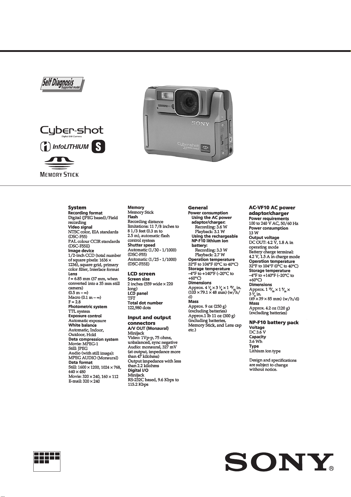
SPECIFICATIONS
US Model
Canadian Model
Tourist Model
DSC-F55
E Model
DSC-F55/F55E
AEP Model
UK Model
Australian Model
Hong Kong Model
Chinese Model
DSC-F55E
MICROFILM
DIGITAL STILL CAMERA
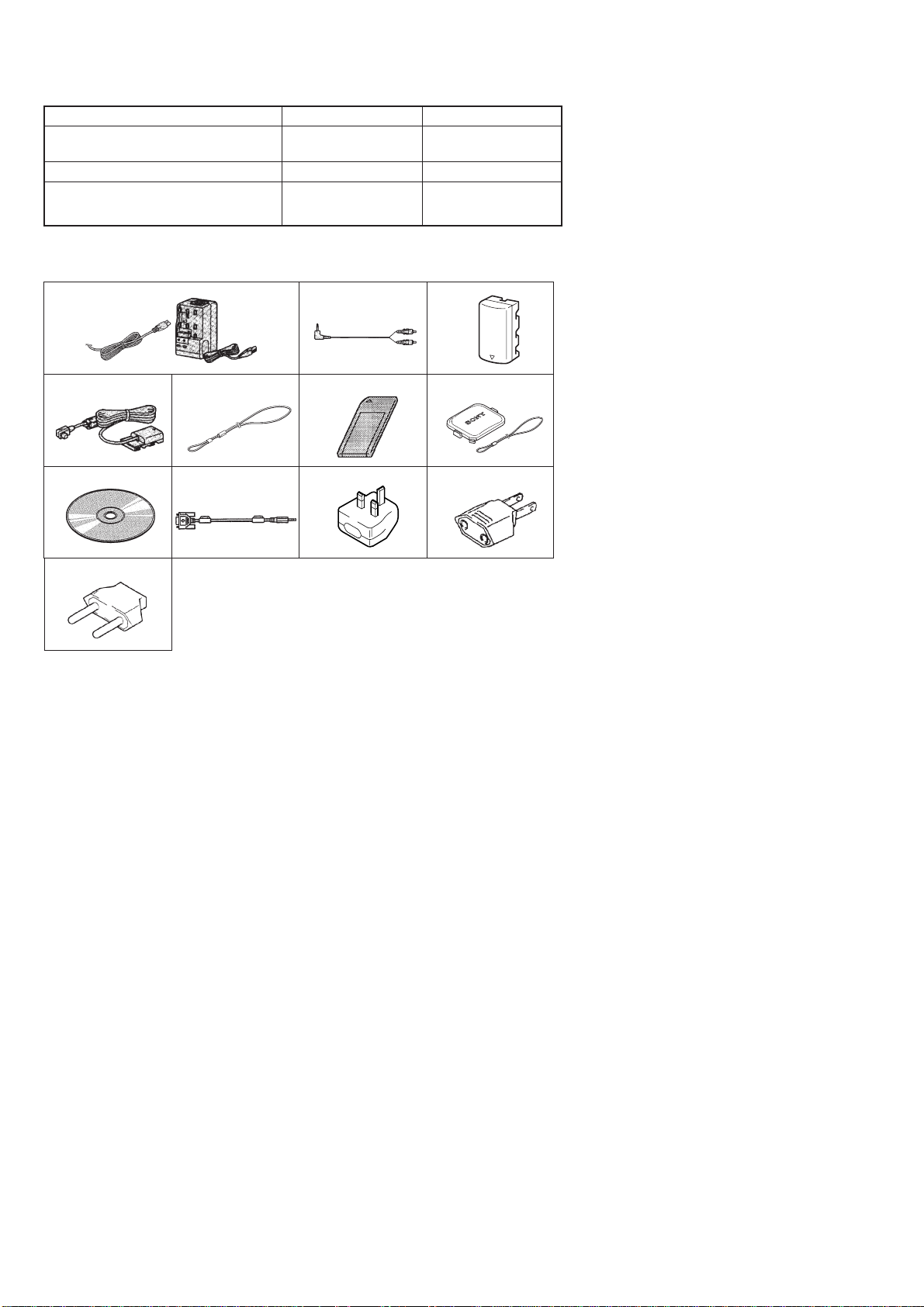
Table for differences of function
Model
Destination
Video signal
Shutter speed
DSC-F55
US, Canadian, Tourist, E
NTSC
Automatic
(1/30 – 1/10000)
DSC-F55E
AEP, UK, Australian,
Hong Kong, Chinese, E
PAL
Automatic
(1/25 – 1/10000)
Supplied accessories
123
4567
89!º!¡
!™
1 AC-VF10 AC power adaptor/charger,
Power cord (1)
2 A/V connecting cable (1)
3 NP-F10 Battery pack (1)
4 DK-115 connecting cord (1)
5 Hand strap (1)
6 Memory Stick (4MB) (1)
7 Lens cap/Lens cap strap (1)
8 Sony Picture Gear 3.2Lite (1)
(Compact Disk)
9 PC serial cable (1)
!º Conversion plug 3P adaptor (1)
UK, Hong Kong model
!¡ 2-pin conversion adaptor (1)
E model
!™ 2-pin conversion adaptor (1)
Tourist model
SAFETY-RELATED COMPONENT WARNING!!
COMPONENTS IDENTIFIED BY MARK ! OR DO TTED LINE WITH
MARK ! ON THE SCHEMATIC DIAGRAMS AND IN THE PARTS
LIST ARE CRITICAL TO SAFE OPERATION. REPLACE THESE
COMPONENTS WITH SONY PARTS WHOSE PART NUMBERS
APPEAR AS SHOWN IN THIS MANUAL OR IN SUPPLEMENTS
PUBLISHED BY SONY.
SAFETY CHECK-OUT
After correcting the original service problem, perform the following
safety checks before releasing the set to the customer.
1. Check the area of your repair for unsoldered or poorly-soldered
connections. Check the entire board surface for solder splashes
and bridges.
2. Check the interboard wiring to ensure that no wires are
"pinched" or contact high-wattage resistors.
3. Look for unauthorized replacement parts, particularly
transistors, that were installed during a previous repair . Point
them out to the customer and recommend their replacement.
ATTENTION AU COMPOSANT AYANT RAPPORT
À LA SÉCURITÉ!
LES COMPOSANTS IDENTIFÉS P AR UNE MARQUE ! SUR LES
DIAGRAMMES SCHÉMA TIQUES ET LA LISTE DES PIÈCES SONT
CRITIQUES POUR LA SÉCURITÉ DE FONCTIONNEMENT. NE
REMPLACER CES COMPOSANTS QUE PAR DES PIÈSES SONY
DONT LES NUMÉROS SONT DONNÉS DANS CE MANUEL OU
DANS LES SUPPÉMENTS PUBLIÉS PAR SONY.
4. Look for parts which, through functioning, show obvious signs
of deterioration. Point them out to the customer and
recommend their replacement.
5. Check the B+ voltage to see it is at the values specified.
6. Flexible Circuit Board Repairing
• Keep the temperature of the soldering iron around 270˚C
during repairing.
• Do not touch the soldering iron on the same conductor of the
circuit board (within 3 times).
• Be careful not to apply force on the conductor when soldering
or unsoldering.
— 2 —

TABLE OF CONTENTS
SERVICE NOTE ····································································· 5
1. GENERAL
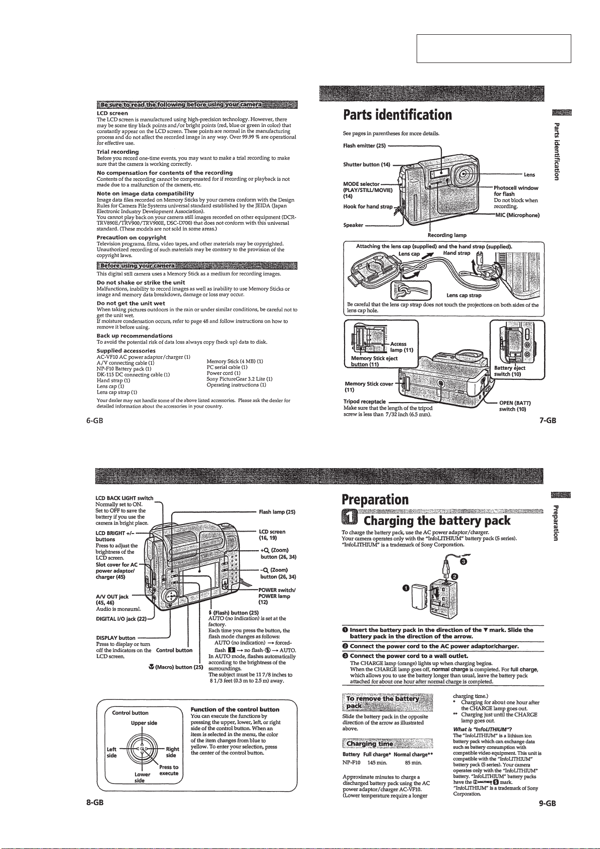
Parts identification·····································································1-1
Preparation·················································································1-1
1 Charging the battery pack ···················································1-1
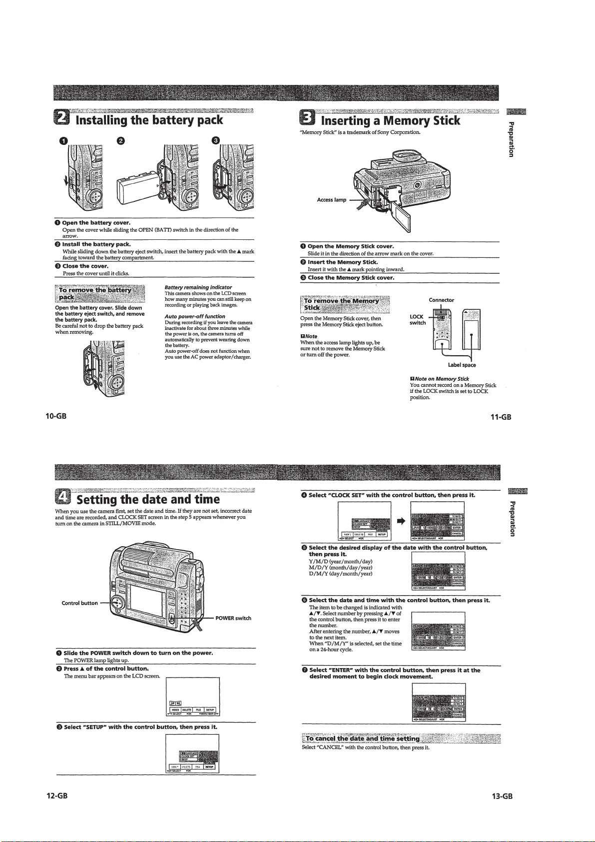
2 Installing the battery pack···················································1-2
3 Inserting a Memory Stick ···················································1-2
4 Setting the date and time·····················································1-2
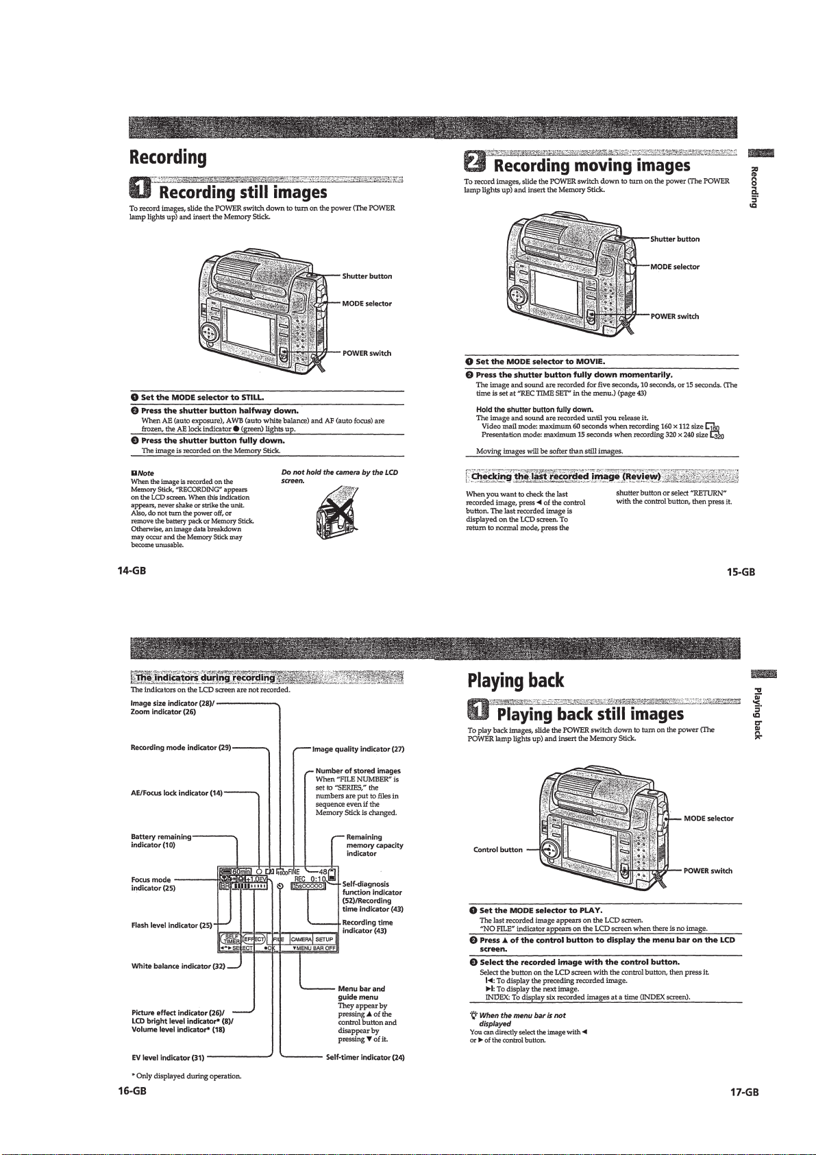
Recording ·················································································· 1-3
1 Recording still images ························································1-3
2 Recording moving images ··················································1-3
Playing back ··············································································1-3
1 Playing back still images ····················································1-3
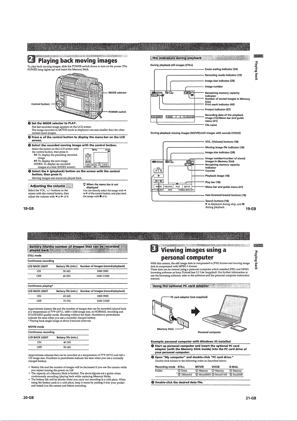
2 Playing back moving images ··············································1-4
3 Viewing images using a personal computer························1-4
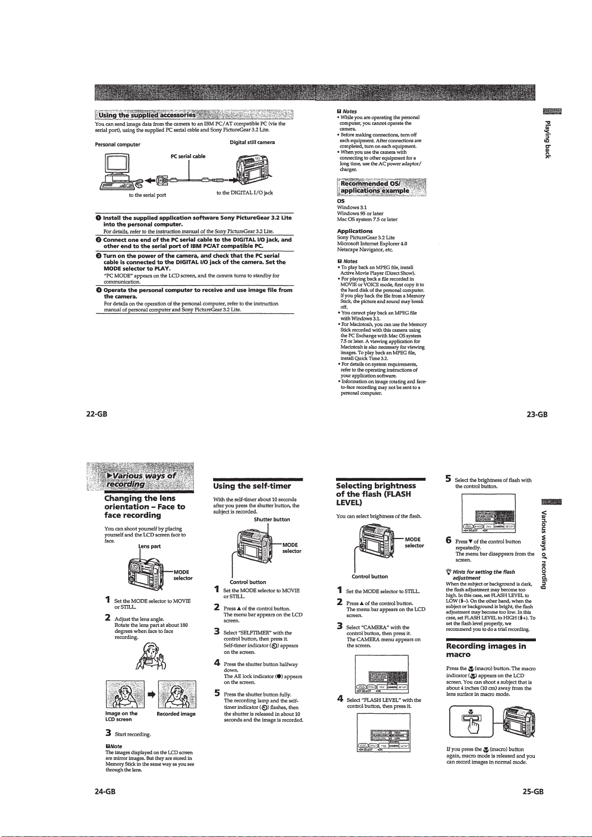
Various ways of recording ·························································1-5
Changing the lens orientation – Face to face recording·········1-5
Using the self-timer ·······························································1-5
Selecting brightness of the flash (FLASH LEVEL) ··············1-5
Recording images in macro ···················································1-5
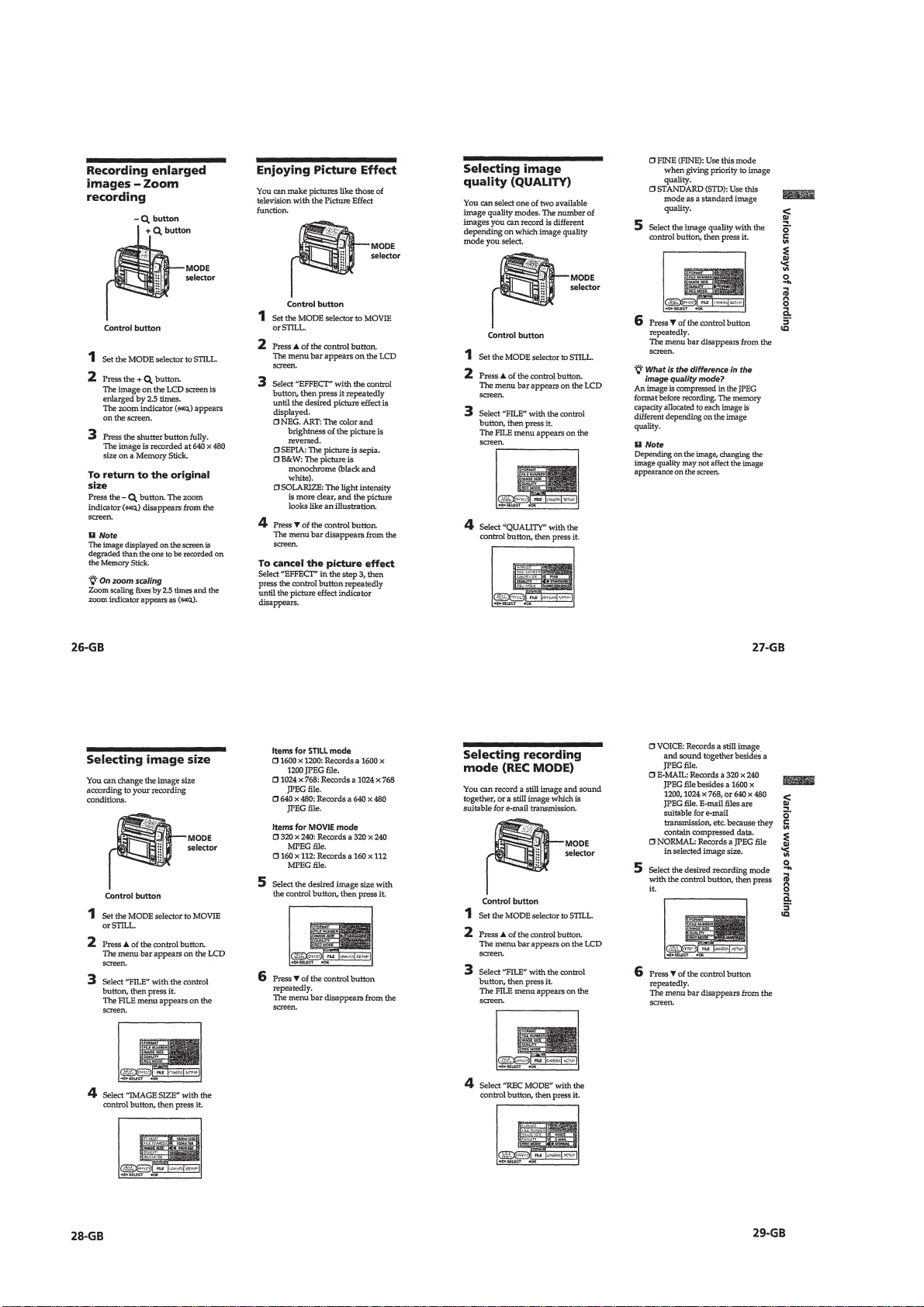
Recording enlarged images – Zoom recording······················1-6
Enjoying Picture Effect··························································1-6
Selecting image quality (QUALITY) ····································1-6
Selecting image size ······························································ 1-6
Selecting recording mode (REC MODE) ······························1-6
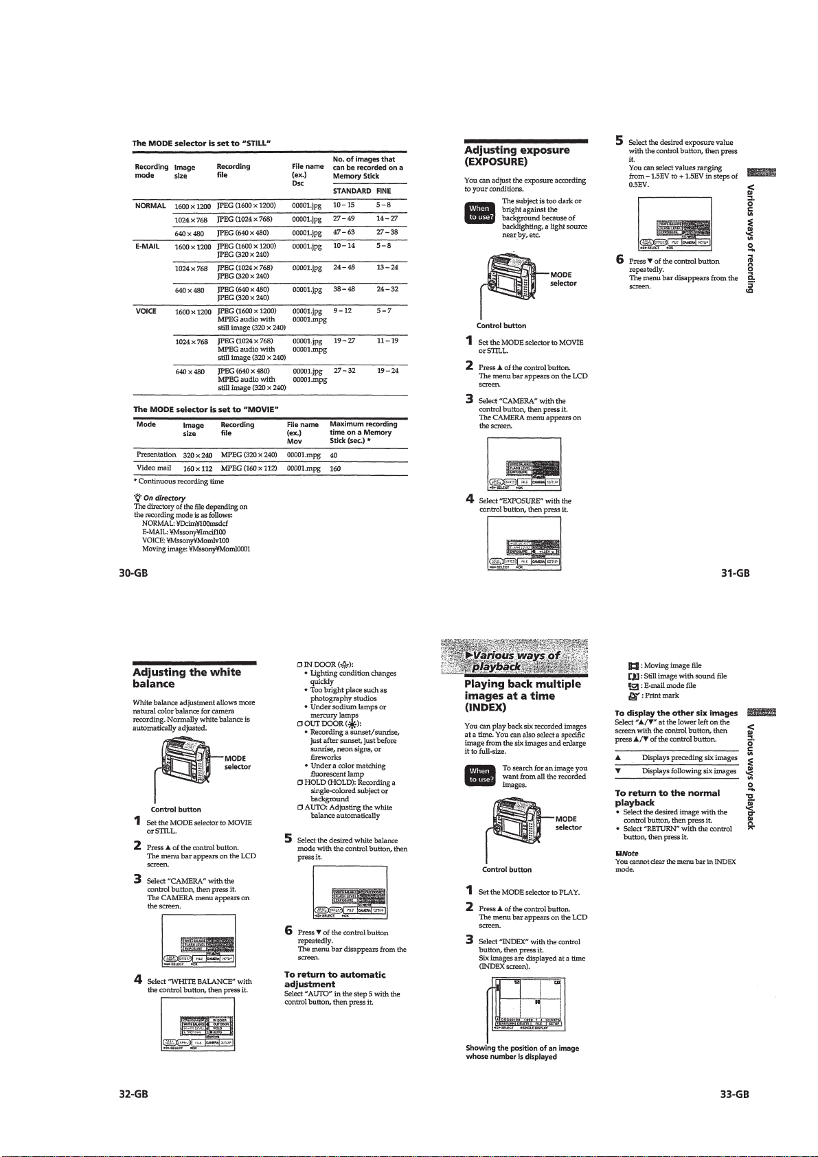
Adjusting exposure (EXPOSURE)········································1-7
Adjusting the white balance···················································1-7
Various ways of playback ··························································1-7
Playing back multiple images at a time (INDEX) ·················1-7
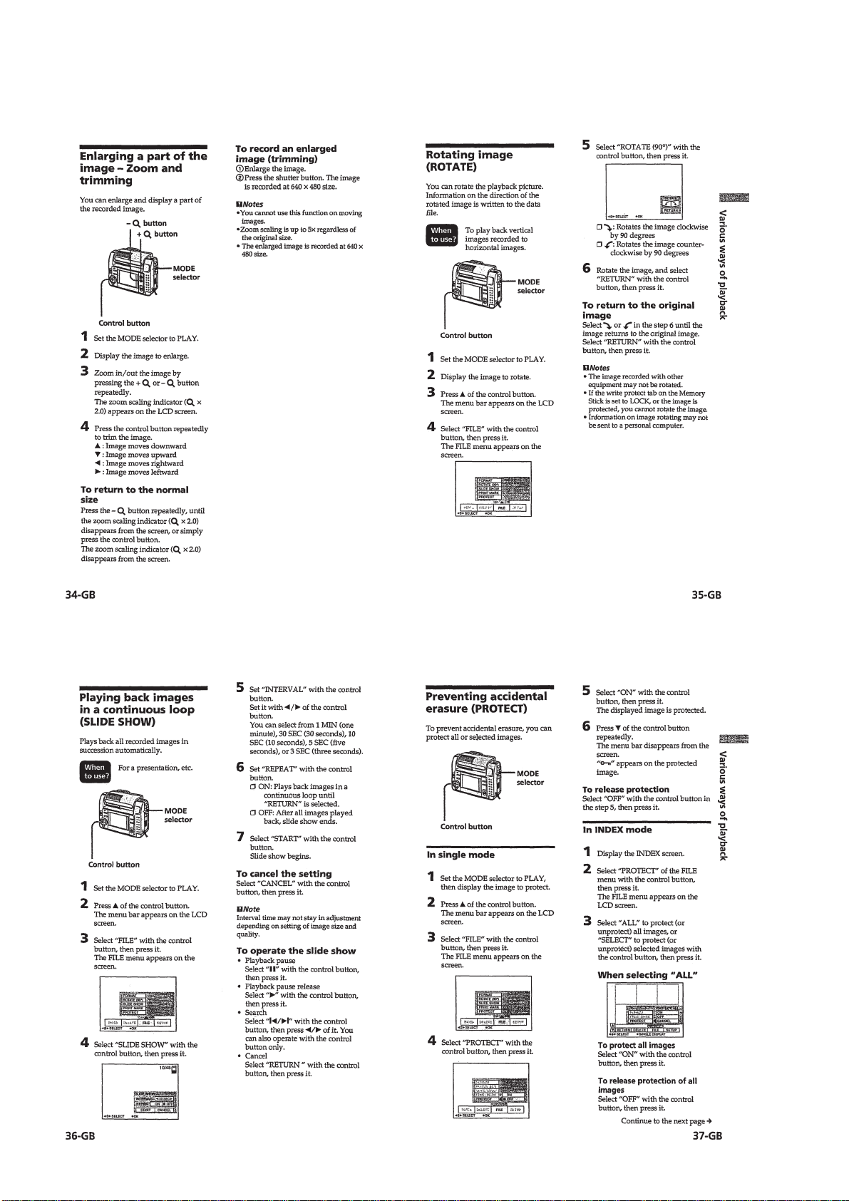
Enlarging a part of the image – Zoom and trimming ············1-8
Rotating image (ROTATE) ····················································1-8
Playing back images in a continuous loop (SLIDE SHOW)··1-8
Preventing accidental erasure (PROTECT) ···························1-8
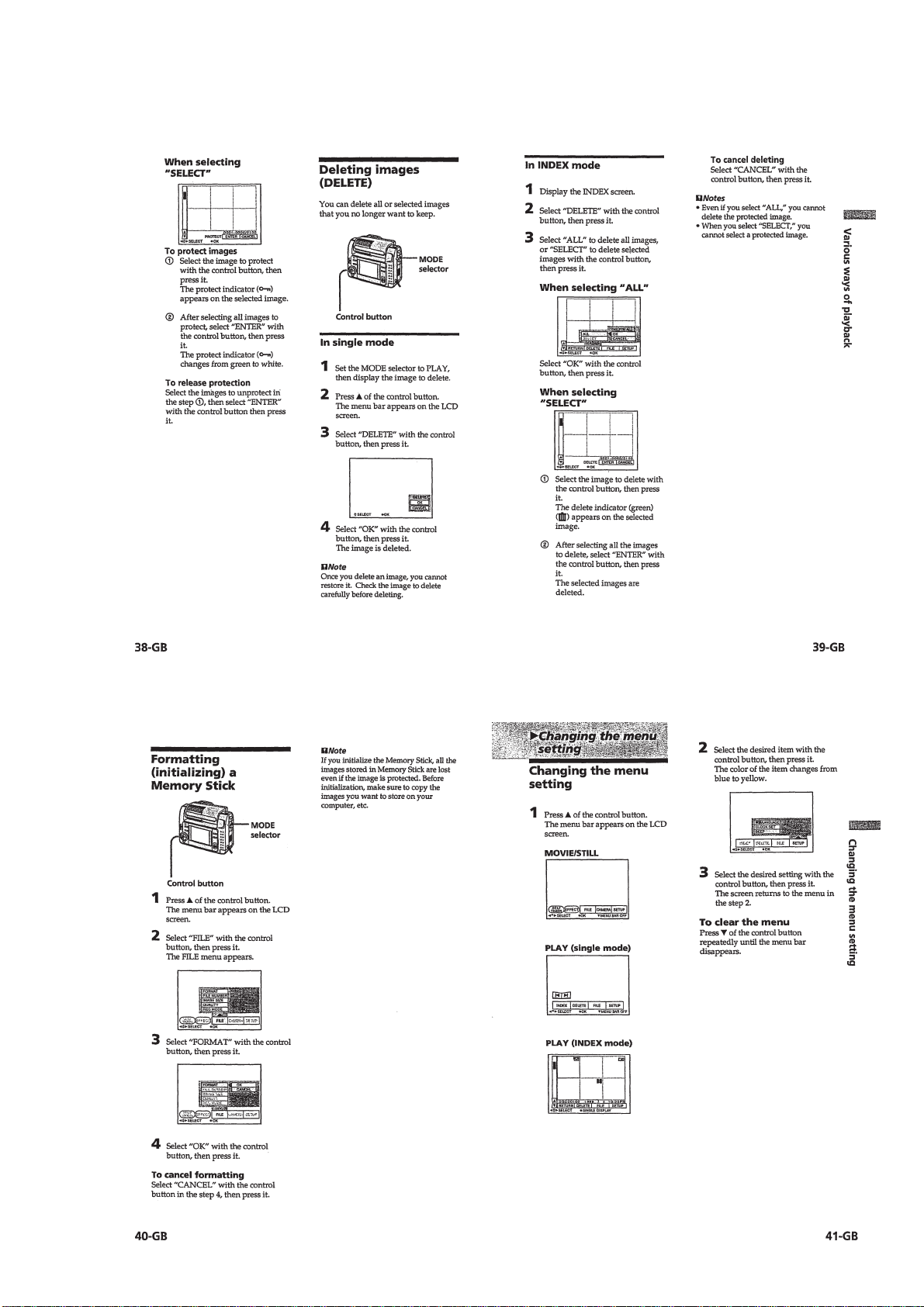
Deleting images (DELETE) ·················································· 1-9
Formatting (initializing) a Memory Stick······························1-9
Changing the menu setting ························································1-9
Changing the menu setting ····················································1-9
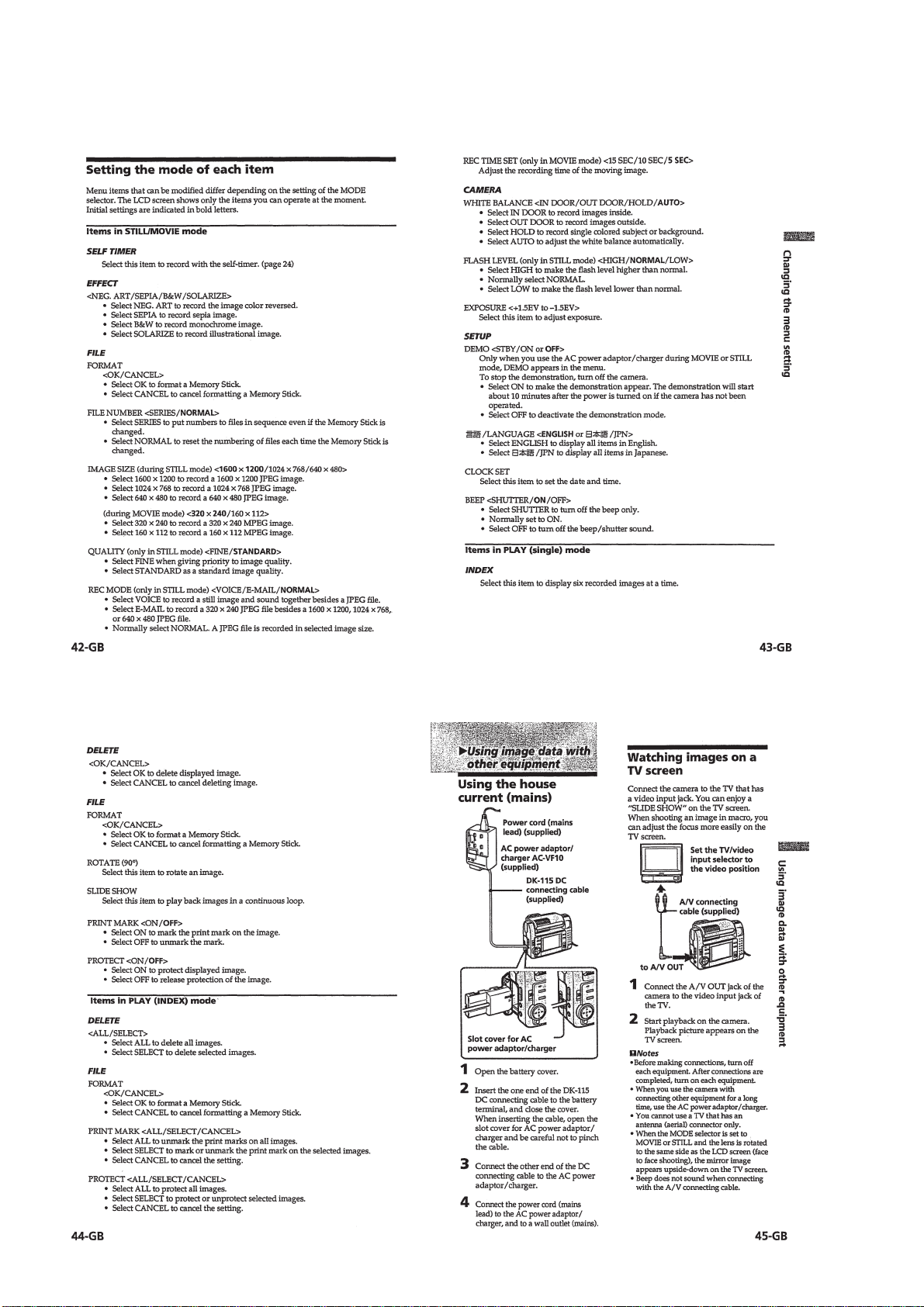
Setting the mode of each item ············································· 1-10
Using image data with other equipment ··································1-10
Using the house current (mains) ·········································· 1-10
Watching images on a TV screen ········································ 1-10
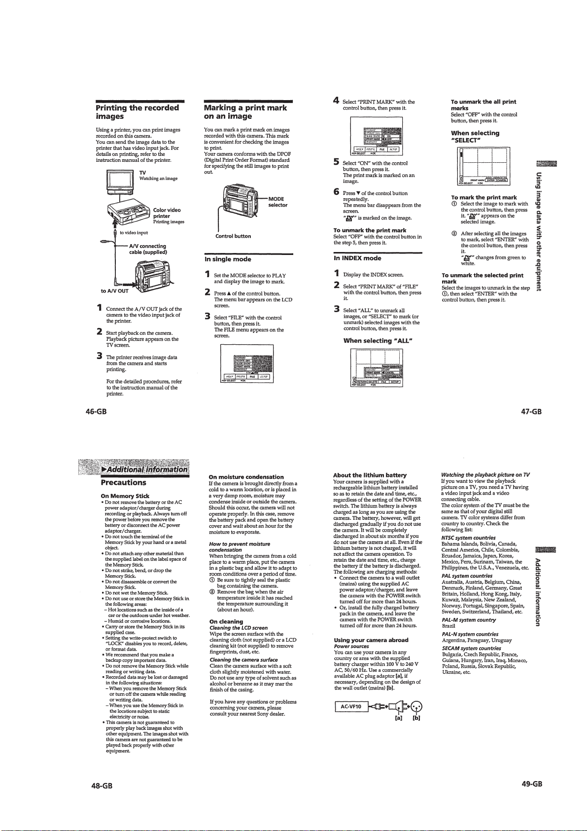
Printing the recorded images ···············································1-11
Marking a print mark on an image ······································ 1-11
Additional information ····························································1-11
Precautions···········································································1-11
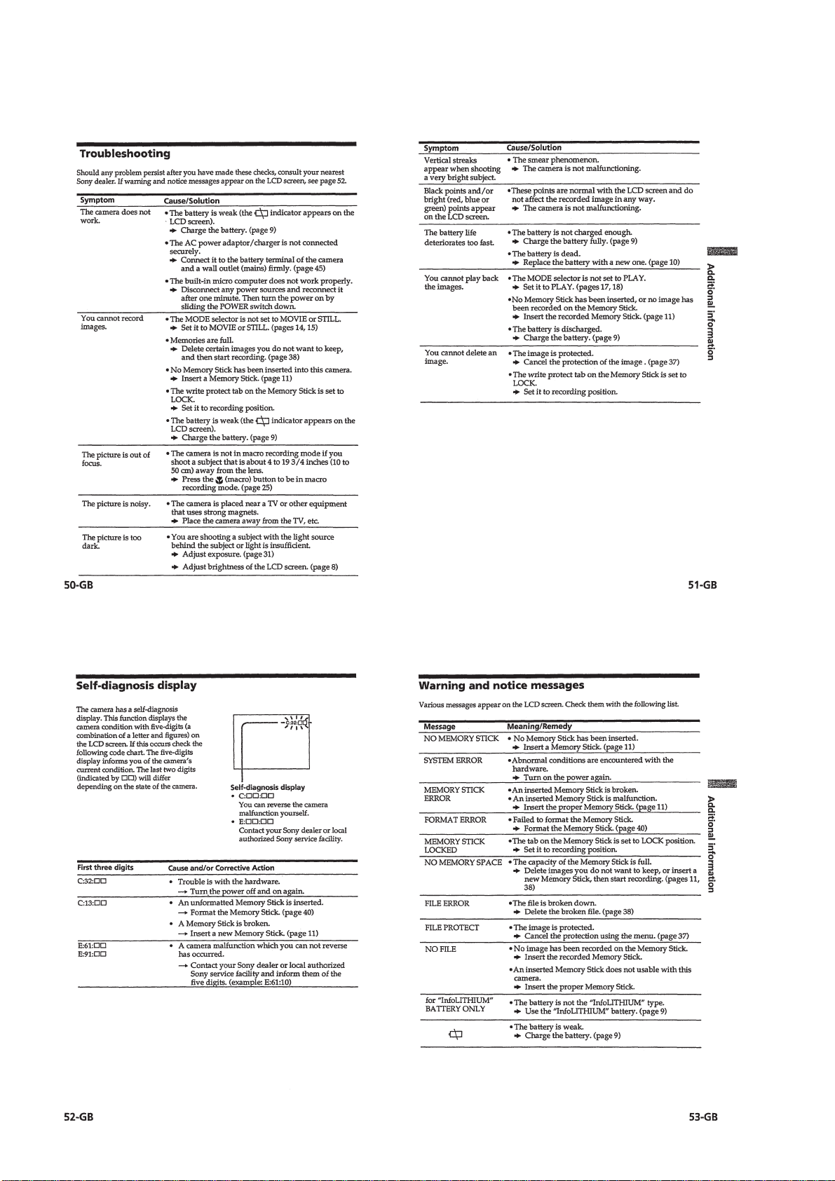
Troubleshooting ···································································1-12
Self-diagnosis display ··························································1-12
Warning and notice messages ··············································1-12
2. DISASSEMBLY
2-1. Cabinet (front) Assembly and Check Cover ····················2-1
2-2. DD-126 Board ·································································2-2
2-3. Lens Cabinet Assembly···················································2-2
2-4. Lens Assembly, Microphone, Flash Unit ························2-3
2-5. MM-39, SY-54 Boards ···················································· 2-4
2-6. Control Switch Block (MS)/(HF)····································2-4
2-7. LCD Panel Block·····························································2-5
2-8. Circuit Boards Location ··················································2-6
2-9. Flexible Boards Location ················································2-6
3. BLOCK DIAGRAMS
3-1. Overall Block Diagram ··················································· 3-1
3-2. Camera/Memory Stick Block Diagram (1) ·····················3-4
3-3. Camera/Memory Stick Block Diagram (2) ·····················3-7
3-4. Mode Control Block Diagram ·······································3-11
3-5. LCD Block Diagram ·····················································3-13
3-6. Power Block Diagram ···················································3-16
4. PRINTED WIRING BOARDS AND
SCHEMATIC DIAGRAMS
4-1. Frame Schematic Diagram ··············································4-1
4-2. Printed Wiring Boards and Schematic Diagrams············4-4
• CD-224 (CCD Imager)
Printed Wiring Board and
Schematic Diagram ·········································4-5
• SY-54 (Camera)(1/10)
Schematic Diagram ·········································4-7
• SY-54 (Camera DSP)(2/10)
Schematic Diagram ·······································4-10
• SY-54 (LCD Drive)(3/10)
Schematic Diagram ·······································4-13
• SY-54 (Timing Generator)(4/10)
Schematic Diagram ·······································4-16
• SY-54 (VIDEO)(5/10)
Schematic Diagram ·······································4-19
• SY-54 (SH DSP)(6/10)
Schematic Diagram ·······································4-22
• SY-54 (Serial I/O)(7/10)
Schematic Diagram ·······································4-25
• SY-54 (Audio)(8/10)
Schematic Diagram ·······································4-27
• SY-54 (Lens Motor Drive)(9/10)
Schematic Diagram ·······································4-29
• Control Switch Block (MS/HF)
Schematic Diagram ·······································4-31
• SY-54 (HI Control)(10/10)
Schematic Diagram ·······································4-34
• SY-54 (Camera, Camera DSP, LCD Drive, Timing
Generator, Video, SH DSP, Serial I/O, Audio,
Lens Motor Drive, HI Control)
Printed Wiring Board ····································4-37
• VL-27 (Back Up Battery)
Printed Wiring Board and
Schematic Diagram ·······································4-42
• MM-39 (Memory)
Printed Wiring Board ····································4-43
• MM-39 (Memory)
Schematic Diagram ·······································4-45
• DD-126 (DC-DC Converter)
Printed Wiring Board ····································4-49
• DD-126 (DC-DC Converter)
Schematic Diagram ·······································4-51
5. ADJUSTMENTS
1. Before starting adjustment···············································5-1
1-1. Adjusting items when replacing main parts and boards ····5-2
5-1. ADJUSTMENTS·····························································5-3
1-1. Preparations before Adjustment ······································5-3
1-1-1.List of Service Tools························································5-3
1-1-2.Preparations ·····································································5-4
1-1-3.Discharging of the strobe power supply ··························5-4
1-1-4.Precaution ········································································5-6
1. Setting the Switch····························································5-6
2. Order of Adjustments ······················································5-6
3. Subjects ···········································································5-6
1-2. Initialization of B, D, E, F Page Data······························5-7
1-2-1.Initialization of D Page Data ···········································5-7
1. Initializing the D Page Data ············································5-7
2. Modification of D Page Data···········································5-7
3. D Page Table ····································································5-7
1-2-2.Initializing the B, E, F Page Data ·································· 5-10
1. Initializing the B, E, F Page Data ··································5-10
2. Modification of B, E, F Page Data ································5-10
3. F Page Table ··································································5-10
4. E Page Table ··································································5-13
5. B Page Table ··································································5-15
— 3 —

1-3. Video System Adjustments ············································5-18
1. Video Sync Level Adjustment (SY-54 board) ···············5-18
2. Video Burst Level Adjustment (SY-54 board)···············5-18
3. Video Y Level Check (SY-54 board) ·····························5-18
1-4. Camera System Adjustments·········································5-19
1. HALL Adjustment ·························································5-19
2. Flange Back Adjustment (Using Minipattern Box)······· 5-20
3. Flange Back Adjustment
(Using Flange Back Adjustment Chart) ························5-21
4. Flange Back Check························································5-21
5. Picture Frame Setting ····················································5-22
6. F No. Standard Data Input·············································5-22
7. Mechanical Shutter Adjustment ····································5-22
8. Light Level Adjustment ·················································5-23
9. Auto White Balance Standard Data Input ····················· 5-23
10. Auto White Balance Adjustment ···································5-24
11. Color Reproduction Adjustment····································5-25
11-1. Color Reproduction Adjustment····································5-25
11-2. Color Reproduction Check ············································ 5-25
11-3. Processing after Completing Adjustments ····················5-25
12. White Balance Check ····················································5-26
13. Strobe White Balance Adjustment·································5-26
14. Strobe Light Level and White Balance Check ·············· 5-27
15. CCD Defect Compensation ··········································· 5-27
16. CCD Defect Compensation Check································5-28
1-5. LCD System Adjustment···············································5-29
1. LCD Initial Data Input ··················································5-29
2. VCO Adjustment (SY-54 board) ···································5-30
3. D Range Adjustment (SY-54 board) ······························5-30
4. Bright Adjustment (SY-54 board)··································5-31
5. Contrast Adjustment (SY-54 board) ······························5-31
6. Color Adjustment (SY-54 board) ···································5-32
7. V-COM Level Adjustment (SY-54 board) ·····················5-32
8. V-COM Adjustment (SY-54 board) ······························· 5-33
9. White Balance Adjustment (SY-54 board) ····················5-33
1-6. System Control System Adjustment······························5-34
1. Battery End Adjustment (SY-54 board)·························5-34
5-2. SERVICE MODE ··························································5-35
2-1. Adjustment Remote Commander ··································5-35
1. Using the Adjustment Remote Commander··················5-35
2. Precautions Upon Using the Adjustment Remote
Commander ···································································5-35
2-2. Data Process ··································································5-36
2-3. Service Mode·································································5-37
1. Setting the Test Mode ····················································5-37
2. Bit V alue Discrimination ···············································5-37
3. Switch Check (1) ···························································5-38
4. Switch Check (2) ···························································5-38
5. LED Check ····································································5-38
6. REPAIR PARTS LIST
6-1. Exploded Vie ws ·······························································6-1
6-1-1.Overall Section ································································6-1
6-1-2.Cabinet (front) Section ····················································6-2
6-1-3.Camera Block Section ·····················································6-3
6-1-4.Cabinet (rear) Section······················································6-4
6-2. Electrical Parts List ························································· 6-5
* The color reproduction frame is shown on page 153.
— 4 —
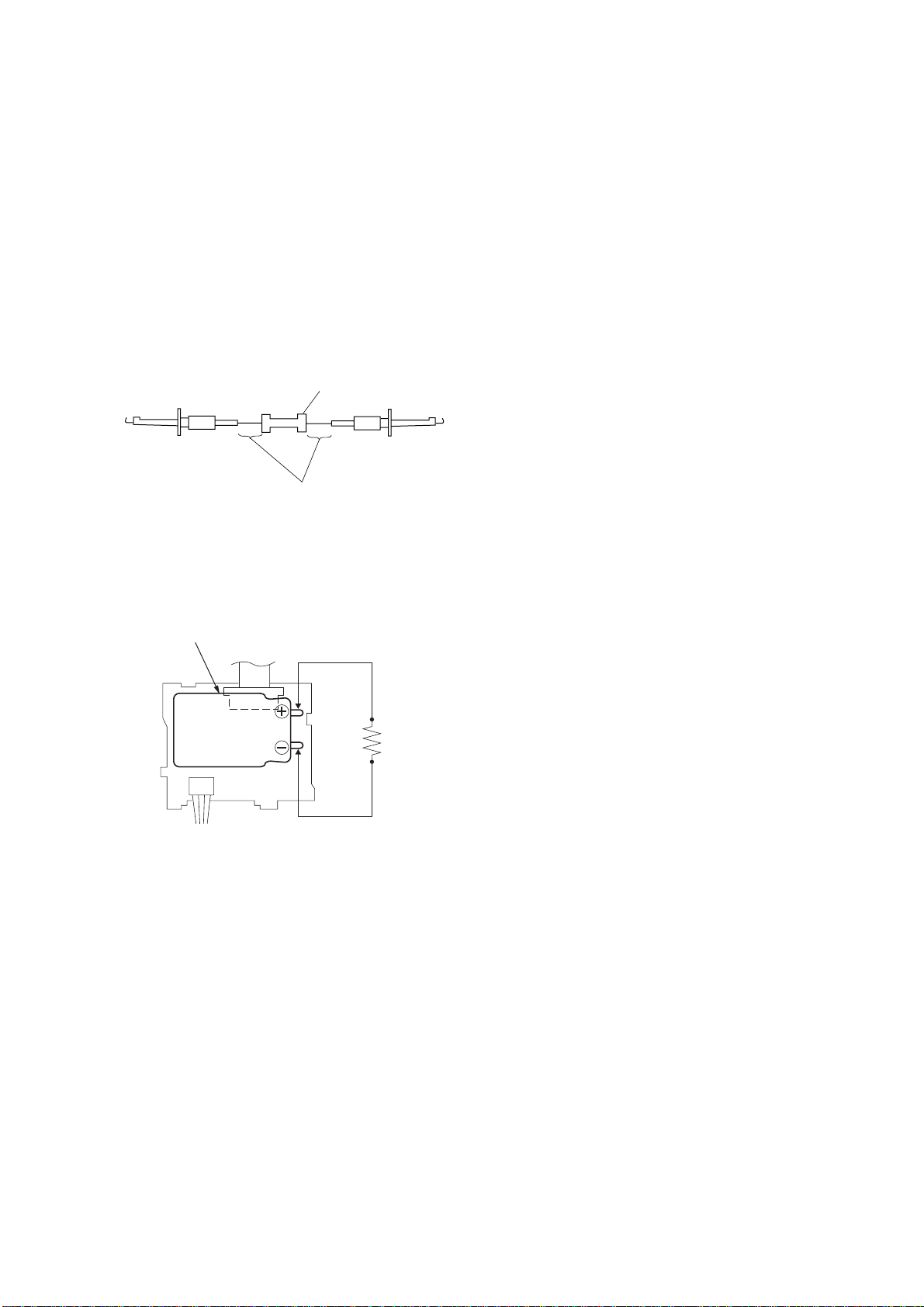
SERVICE NOTE
[Discharging of the FLASH unit’s charging capacitor]
The charging capacitor of the FLASH unit is charged up to the
maximum 300 V potential.
There is a danger of electric shock by this high voltage when the
capacitor is handled by hand. The electric shock is caused by the
charged voltage which is kept without discharging when the main
power of the DSC-F55/F55E is simply turned off. Therefore, the
remaining voltage must be discharged as described below.
Preparing the Short Jig
To preparing the short jig. a small clip is attached to each end of a
resistor of 1kΩ /1W (1-215-869-11)
Wrap insulating tape fully around the leads of the resistor to prevent
electrical shock.
1kΩ/1W
Wrap insulating tape.
Discharging the Capacitor
Short circuits between the positive and the negative terminals of
charged capacitor with the short jig about 10 seconds.
Capacitor
Short jig
FLASH UNIT
— 5 —
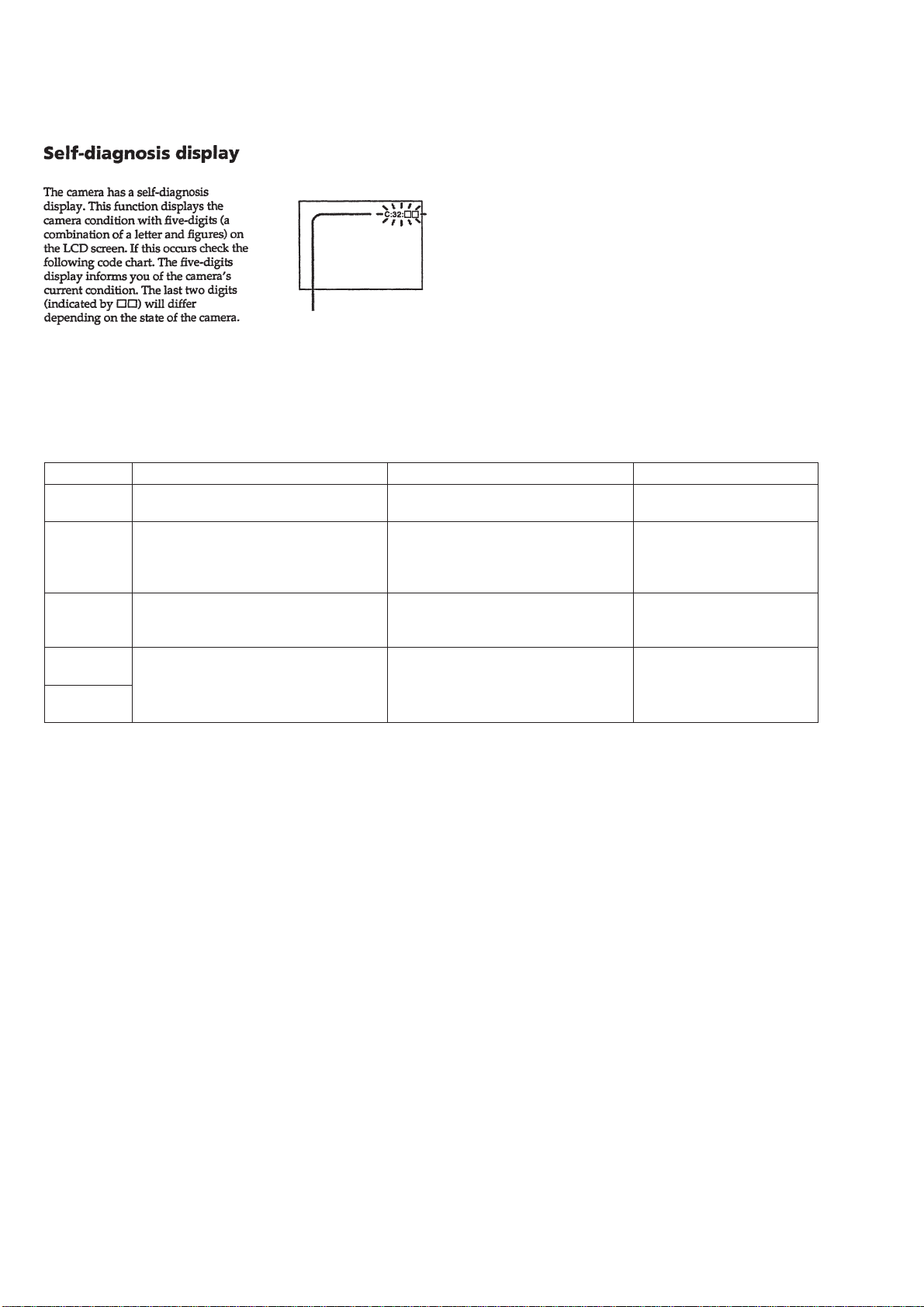
[Description on Self-diagnosis Display]
Self-diagnosis display
• C: ππ: ππ
The contents which can be handled
by customer, are displayed.
• E: ππ: ππ
The contents which can be handled
by engineer, are displayed.
Note : The “Self-diagnosis” data is backed up by the coin lithium
battery.The data will be lost and initialized when the coin lithium
battery is removed.
Display Code
C:32:01
C:13:01
E:91:01
E:61:00
E61:10
Countermeasure
Turn off the main power then back on.
Replace the memory stick.
Format the memory stick with the DSCF55/F55E.
Checking of flash unit or replacement of
flash unit
Checking of lens drive circuit
Cause
Trouble with hardware.
• The type of memory stick that cannot
be used by this machine, is inserted.
• Data is damaged.
• Unformatted memory stick is inserted.
Abnormality when flash is being
charged.
When failed in the focus initialization.
Caution Display During Error
SYSTEM ERROR
MS ERROR
Flash LED
Flash display
Flashing at 3.2 Hz
—
— 6 —
SECTION 1
GENERAL
DSC-F55/F55E
This section is extracted from
instruction manual. (DSC-F55/F55E)
1-1
1-2
1-3
1-4
1-5
1-6
1-7
1-8
1-9
1-10
1-11
1-12E
SECTION 2
DISASSEMBLY
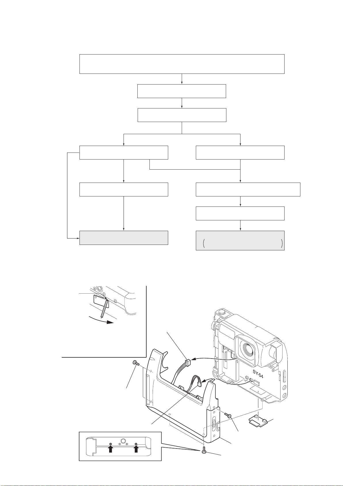
The following flow chart shows the disassembly procedure.
DSC-F55/F55E
2-1. CABINET (FRONT) ASSEMBLY AND CHECK COVER
2-2. DD-126 BOARD
2-3. LENS CABINET ASSEMBLY 2-5. MM-39, SY-54 BOARDS
DSC-F55/F55E
2-4. LENS ASSEMBLY,
MICROPHONE, FLASH UNIT
SERVICE POSITION 1
(FLASH UNIT, LENS BLOCK)
2-6. CONTROL SWITCH BLOCK (MS) / (HF)
2-7. LCD PANEL BLOCK
SERVICE POSITION 2
DD-126 BOARD, MM-39 BOARD,
SY-54 BOARD, LCD PANEL BLOCK
NOTE: Follow the disassembly procedure in the numerical order given.
2-1. CABINET (FRONT) ASSEMBLY AND CHECK COVER
P
(Fig 1)
Remove the check cover by rotating
the metal bar in the direction of the
arrow of ø1.6 or less centering around
the point “P”.
Note: Do not reuse the check cover
that is once removed.
4
Connector
CN001 3P (MM-39 board)
3
Two screws (lock ace M1.7)
5
Harness (SV-110)
CN605 2P (SY-54 board)
2-1
7
(Refer to Fig 1)
1
Screw (lock ace M1.7)
6
Cabinet (front) assembly
2
Two screws (lock ace M1.7)
Check cover
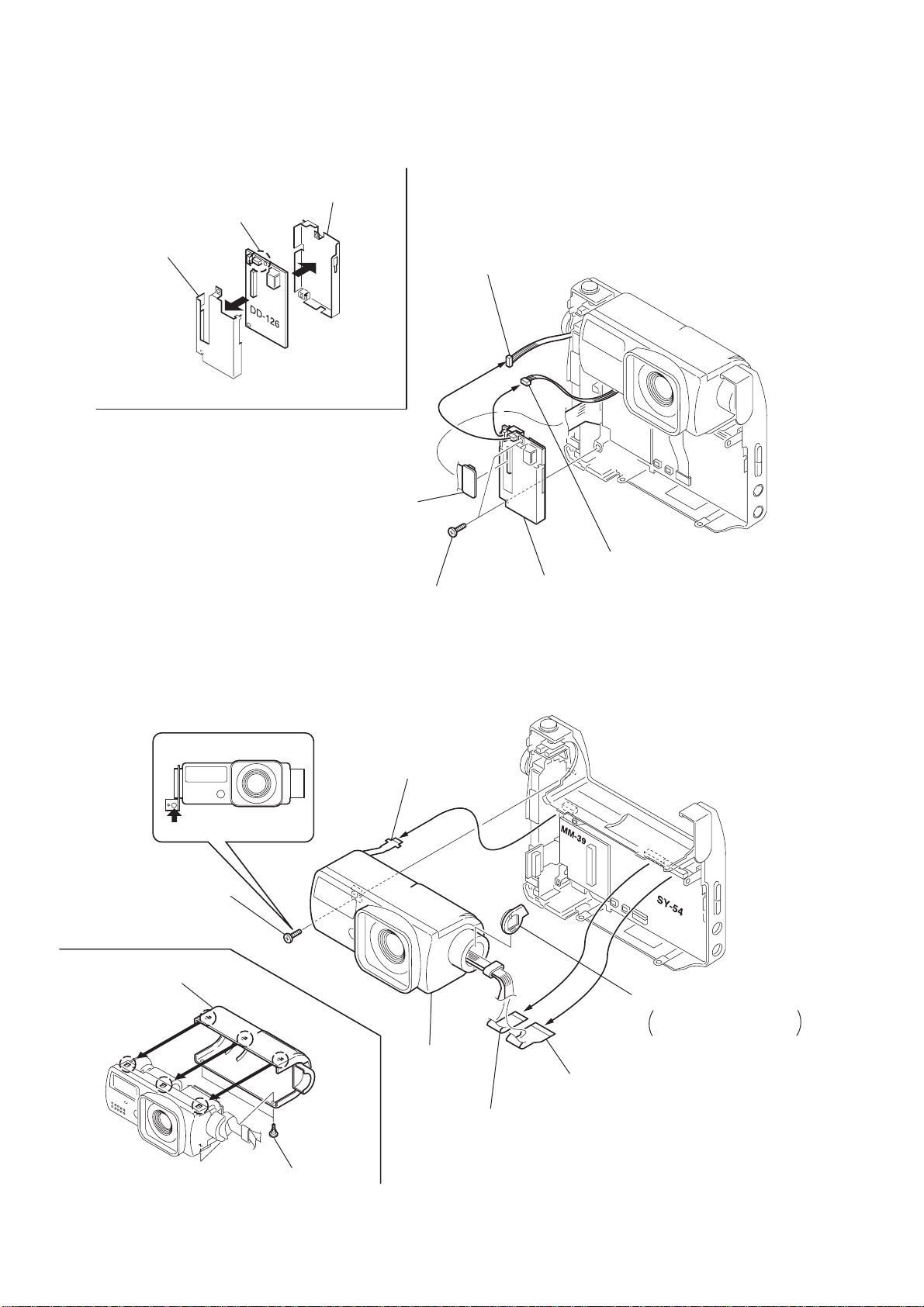
2-2. DD-126 BOARD
6
Remove the solder.
7
DD shield case B
8
DD shield case A
1
FP-109 flexible board
CN004 (DD-126)
3
Connector
CN002 3P (DD-126 board)
5
2
Two screws
(lock ace M1.7)
DD-126 board
4
Connector
CN601 5P (DD-126 board)
2-3. LENS CABINET ASSEMBLY
4
Screw
(Tapping head (2 lock) )
8
Lens cabinet (rear) assembly
(Remove the three claws.)
3
FP-108 flexible board
CN604 (SY-54 board)
5
Lens block
2
Flexible board (cam motor)
CN201 (SY-54 board)
6
Flexible stabilizer
Be careful when handling
it as it is not fixed.
1
FP-107 flexible board
CN151 (SY-54 board)
7
Two step screws
2-2
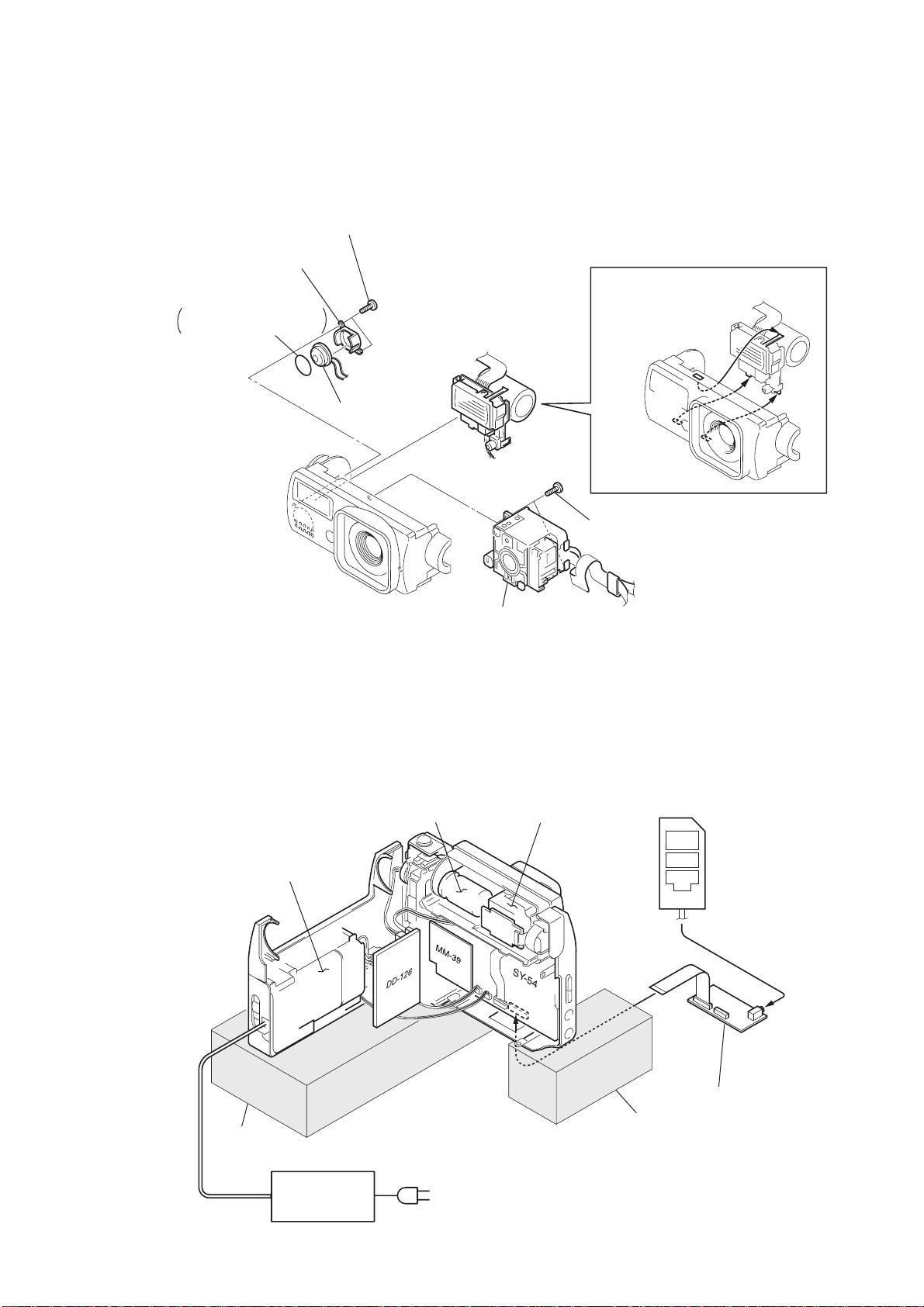
2-4. LENS ASSEMBLY, MICROPHONE, FLASH UNIT
Note : The built-in charging capacitor inside the FLASH unit is charged to the maximum of 300 V.
There is a danger of electric shock due to the high voltage when the capacitor is handed by
bare hand. Discharge the voltage remained in the capacitor, referring to the Service Note (See page 5).
4
Two screws (tapping head (2 lock) )
5
Microphone retainer
7
Microphone cushion
Be careful when handling
it as it is not fixed.
6
Microphone unit
3
Flash unit
(Remove the three claws as shown.)
1
Two screws (tapping head (2 lock) )
2
Lens assembly
[ SERVICE POSITION 1 (FLASH UNIT, LENS BLOCK) ]
Note 1: The built-in charging capacitor inside the FLASH unit is charged to the maximum of 300 V.
There is a danger of electric shock due to the high voltage when the battery is handed by
bare hand. Discharge the voltage remained in the battery, referring to the Service Note (See page 5).
Flash unit
Battery box
Lens block
Adjustment remote
commander (RM-95)
Base
AC power
adaptor
CPC-9 jig
Base
Note 2: The old CPC-9 jig (Parts code: J-6082-393-B)
cannot be used, because it cannot operate
the adjustment remote commander.
(J-6082-393-C) (Note 2)
2-3
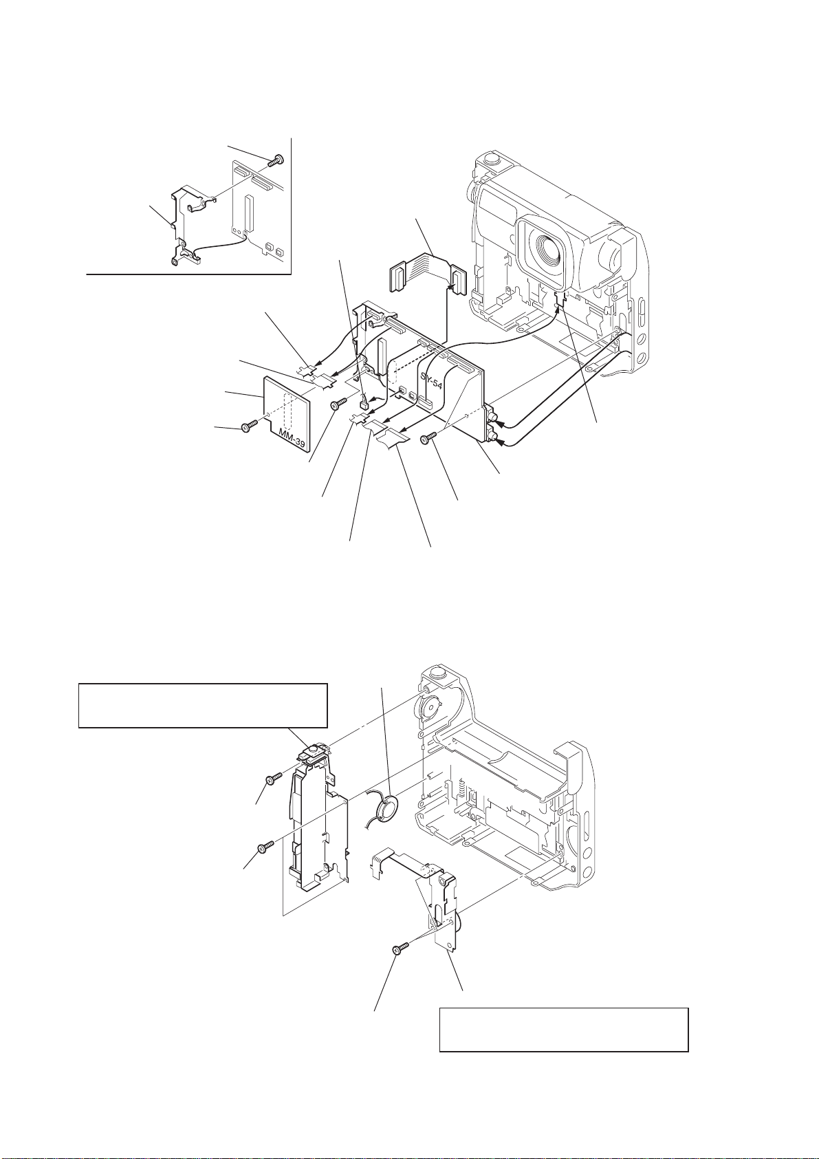
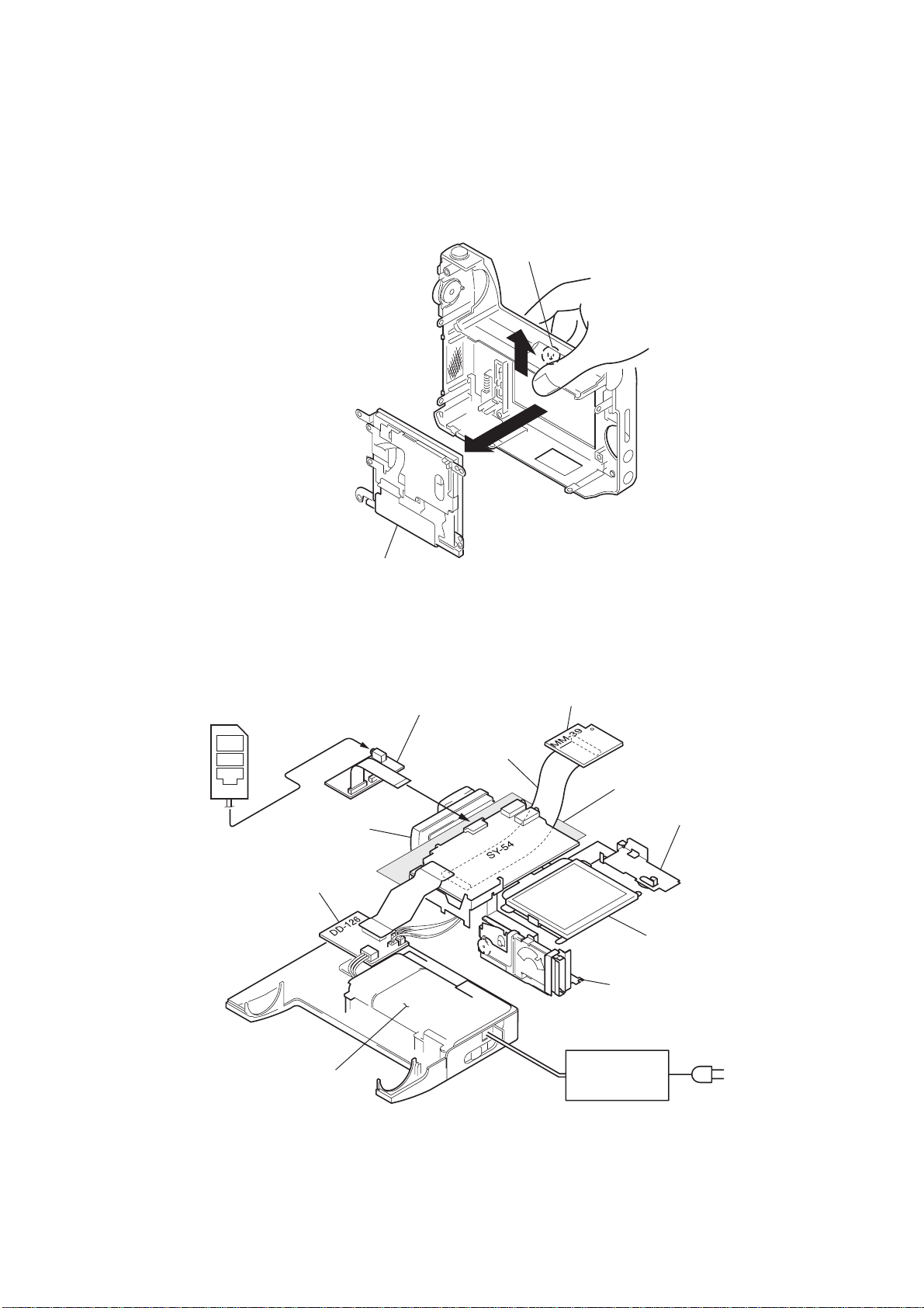
2-5. MM-39, SY-54 BOARDS
!¢
Screw (lock ace M1.7)
!∞
DD flame
4
FP-108 flexible board
CN604 (SY-54 board)
5
Flexible board
(Control switch block (MS) )
CN603 (SY-54 board)
2
MM-39 board
CN351 (SY-54 board)
1
Screw (lock ace M1.7)
!º
Screw (lock ace M1.7)
6
Flexible board
(Control switch block (HF) )
CN602 (SY-54 board)
!™
FP-109 flexible board
CN601 (SY-54 board)
9
Harness (SS-72)
CN701 (SY-54 board)
3
FP-110 flexible board
CN902 (SY-54 board)
!£
SY-54 board
!¡
Two screws (lock ace M1.7)
7
Flexible board (cam motor)
CN201 (SY-54 board)
2-6. CONTROL SWITCH BLOCK (MS) / (HF)
3
Control switch block (MS)
Precaution to attach the control switch block
Align the switch of the Mode with its knob when
attaching it.
1
Screw
(tapping head (2 lock) )
2
Two screws
(tapping head (2 lock) )
4
Speaker
8
FP-107 flexible board
CN151 (SY-54 board)
5
Three screws
(tapping head (2 lock) )
2-4
6
Control switch block (HF)
Precaution to attach the control switch block
Align the switch of the LCD back light with its
knob when attaching it.
2-7. LCD PANEL BLOCK
• Open the cabinet in the direction of the arrow
display panel block, and remove the LCD panel block in the direction of the arrow
LCD panel block
A
as shown, release the claw of the LCD
Claw
A
B
B
.
[ SERVICE POSITION 2 (DD-126 BOARD, MM-39 BOARD, SY-54 BOARD, LCD PANEL BLOCK) ]
Adjustment remote
commander (RM-95)
DD-126 board
Battery box
CPC-9 jig
(J-6082-393-C) (Note)
Extension cable (80P)
(J-6082-444-A)
Lens block
MM-39 board
Thick isolation sheet
Control switch block (HF)
LCD panel block
Control switch block (MS)
AC power
adaptor
Note: The old CPC-9 jig (Parts code: J-6082-393-B) cannot be used,
because it cannot operate the adjustment remote commander.
2-5
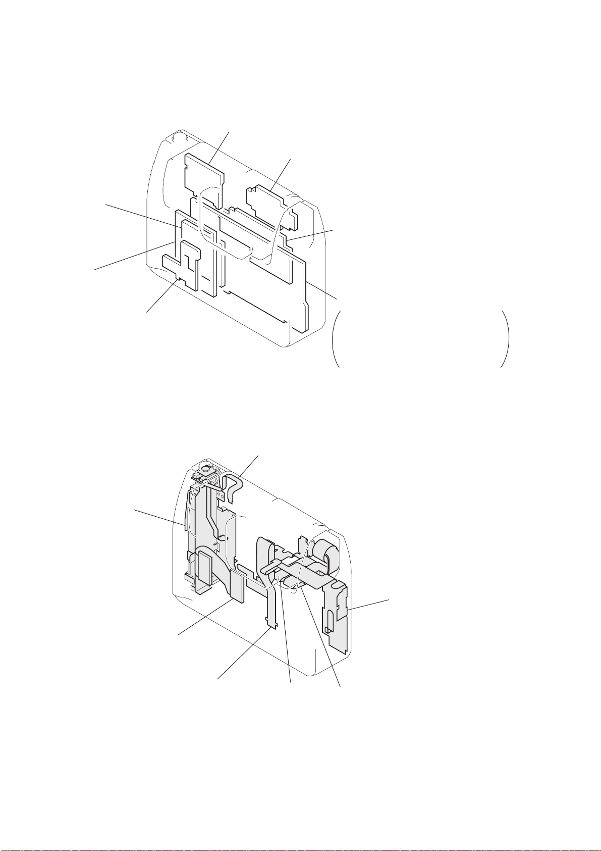
2-8. CIRCUIT BOARDS LOCATION
FLASH UNIT
MM-39
(MEMORY)
DD-126
(DC-DC CONVERTER)
VL-27
(BACK UP BATTERY)
CD-224
(CCD IMAGER)
INVERTER TRANSFORMER UNIT
SY-54
CAMERA, CAMERA DSP,
LCD DRIVE, TIMING GENERATOR,
VIDEO, SH DSP, SERIAL I/O,
AUDIO, LENS MOTOR DRIVE,
HI CONTROL
2-9. FLEXIBLE BOARDS LOCATION
CONTROL SWITCH
BLOCK (MS)
FP-109
FP-110
FP-108
FLEXIBLE BOARD
(CAM MOTOR)
CONTROL SWITCH
BLOCK (HF)
FP-107
2-6E
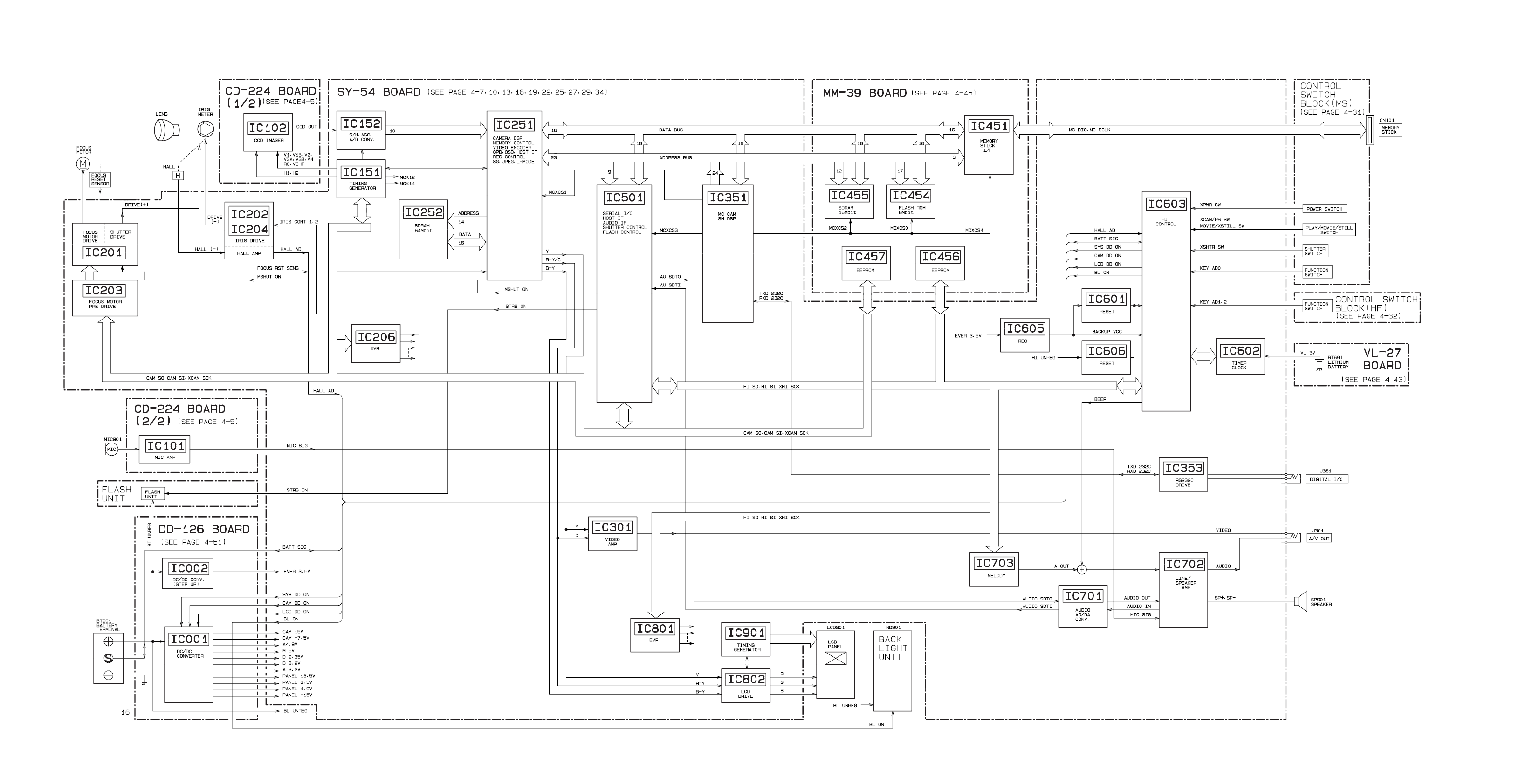
3-1. OVERALL BLOCK DIAGRAM
SECTION 3
DSC-F55/F55E
BLOCK DIAGRAMS
3-1 3-2 3-3
DSC-F55/F55E
IC102 !¢,!ª
6.5Vp-p
IC102 !£,@º
6.5Vp-p
50 µsec/div
2 V/div
50 µsec/div
2 V/div
150 µsec
150 µsec
IC152 @§
1.0Vp-p
50µsec/div
0.5V/div
150 µsec
IC152 2 – 0
3.5Vp-p
50nsec/div
1V/div
100 nsec
IC151 @∞
3.4Vp-p
20nsec/div
1V/div
24.54 MHz (DSC-F55)
24.375 MHz (DSC-F55E)
IC501 $™
1.3Vp-p
50nsec/div
0.5V/div
16.384 MHz
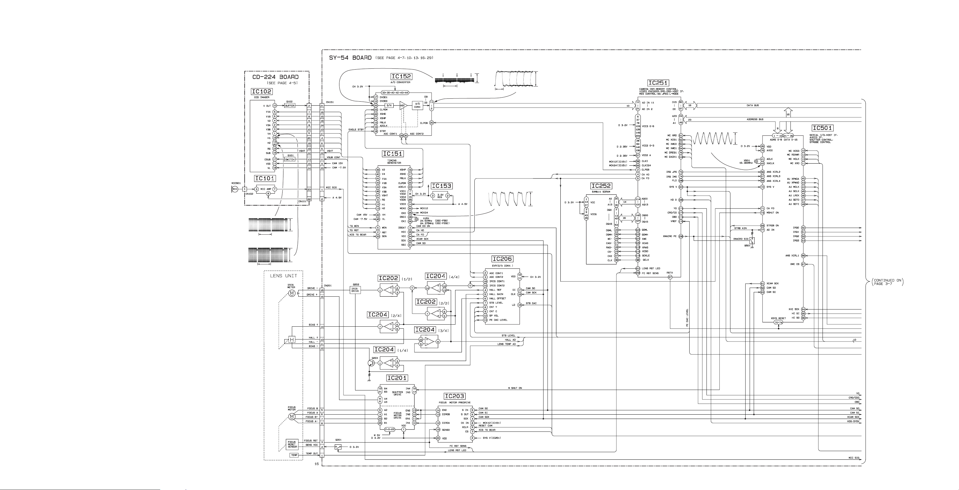
3-2. CAMERA/MEMORY STICK BLOCK DIAGRAM (1)
3-4 3-5 3-6
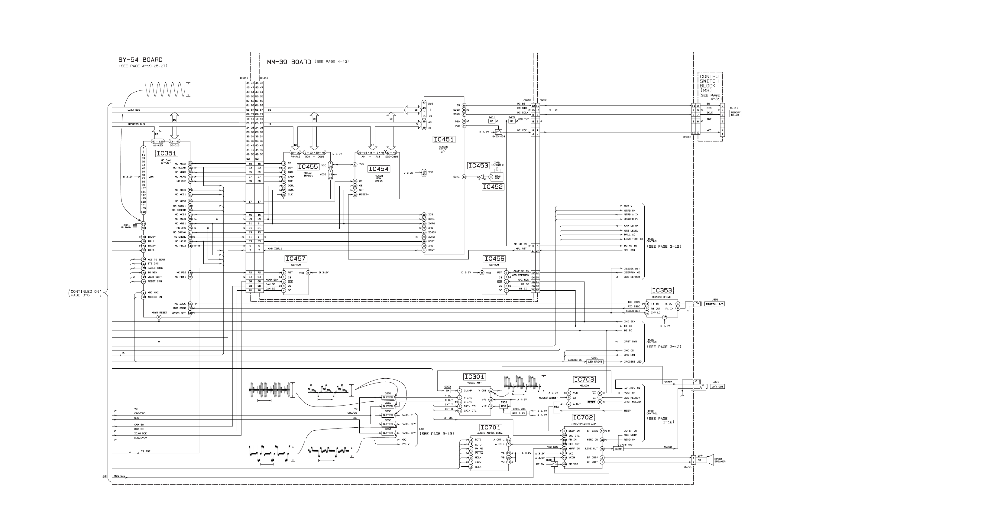
3-3. CAMERA/MEMORY STICK BLOCK DIAGRAM (2)
IC351 !¢ (X351,C354)
DSC-F55/F55E
12.9 MHz
1.5Vp-p
50nsec/div
0.5V/div
Q252 E A/V OUT
H
Q253 E LCD
H
0.36Vp-p
20µsec/div
0.1V/div
20µsec/div
0.1V/div
0.36Vp-p
Q251 E,
Q255 E
Q254 E LCD
IC301 !™ A/V OUT
20µsec/div
0.2V/div
H
0.46Vp-p
0.18Vp-p
H
20µsec/div
0.1V/div
H
2.0Vp-p
20µsec/div
0.5V/div
3-7 3-8 3-9
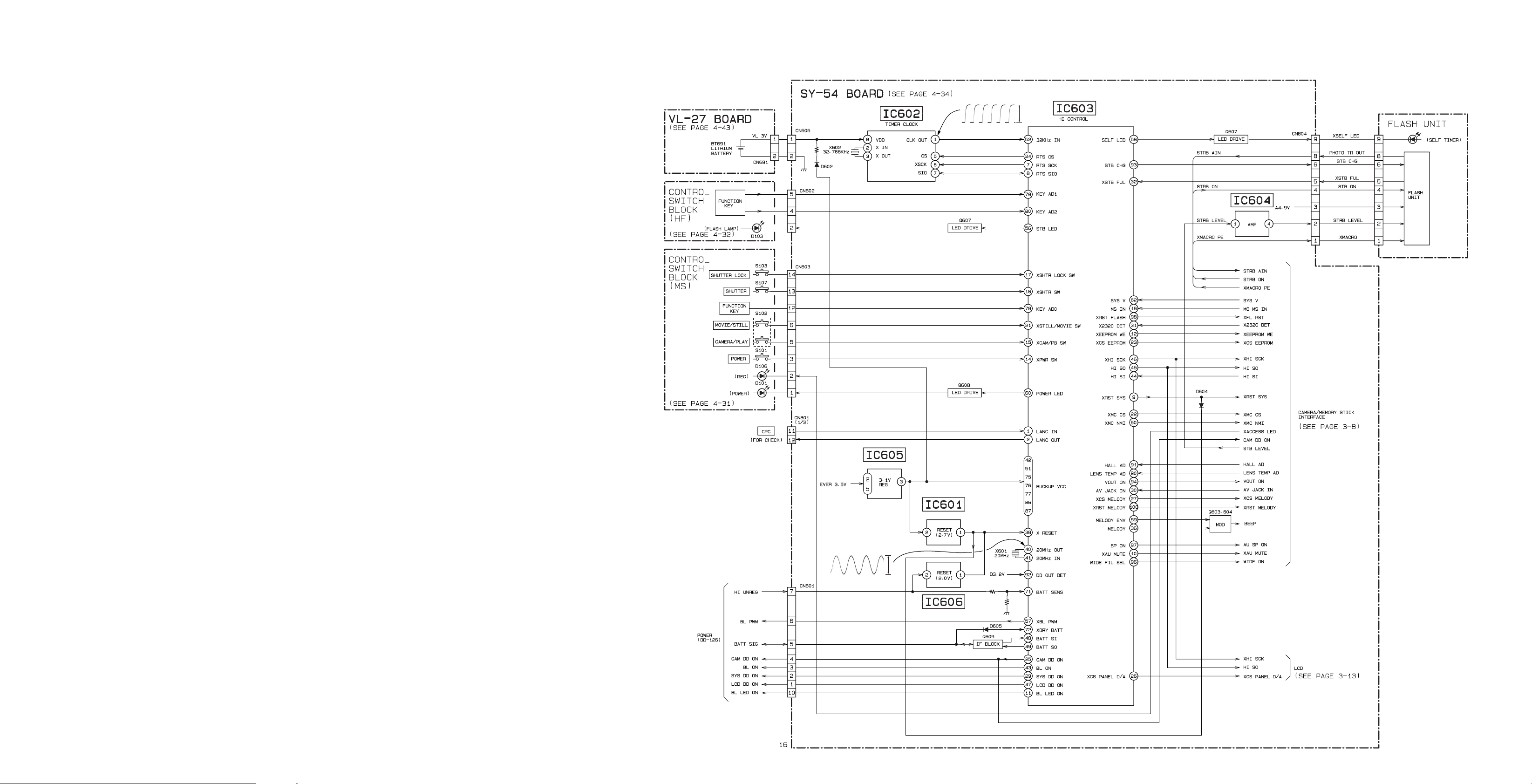
DSC-F55/F55E
IC602 1
20µsec/div
1V/div
3.0Vp-p
32.768 kHz
IC603 $º 20MHz OUT
3.0Vp-p
20nsec/div
1V/div
20 MHz
DSC-F55/F55E
3-4. MODE CONTROL BLOCK DIAGRAM
3-11 3-12
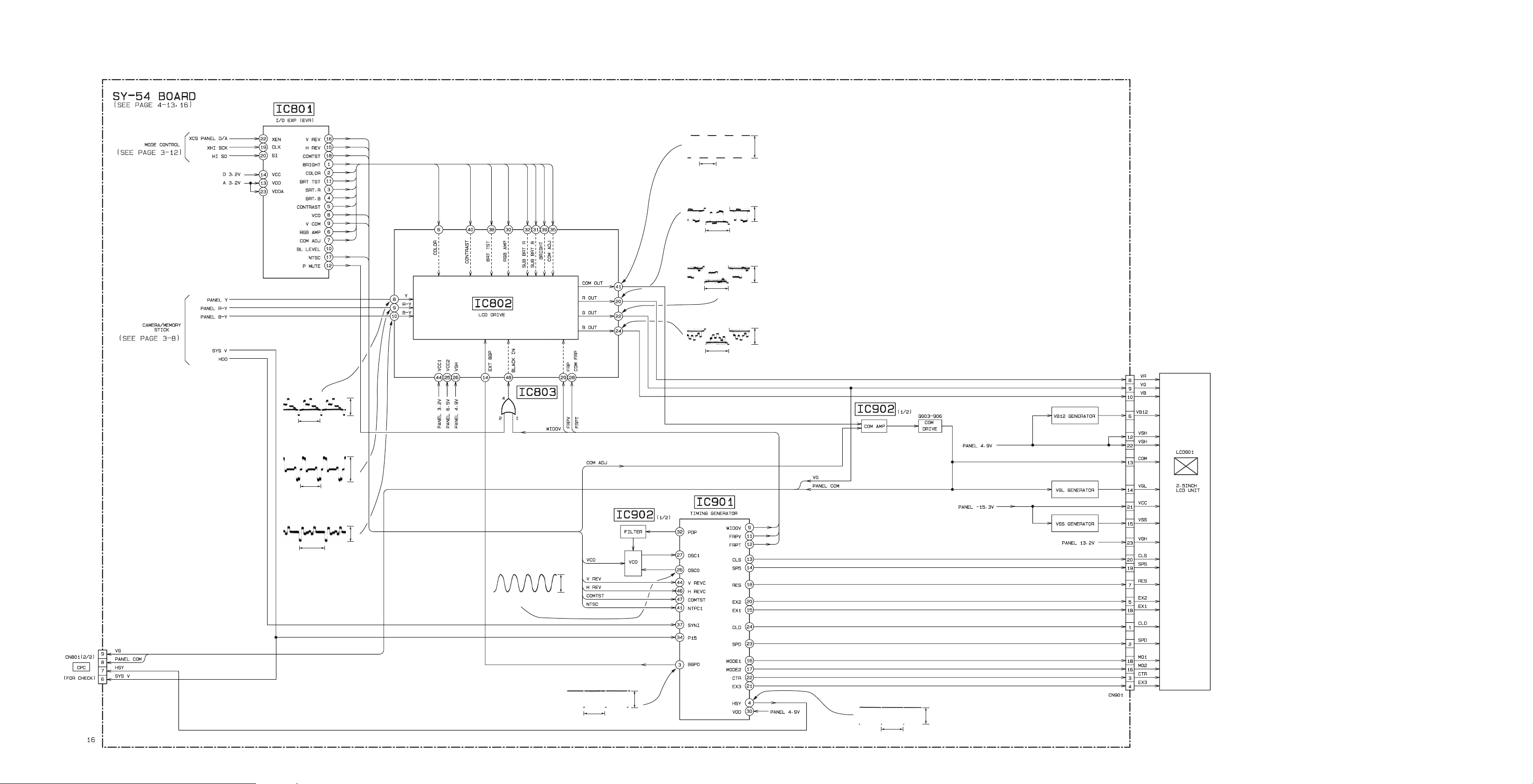
3-5. LCD BLOCK DIAGRAM
DSC-F55/F55E
IC802 8
IC802 $¡ LCD
2H
IC802 @º
IC802 @™
IC802 @¢
50µsec/div
0.5V/div
1.7Vp-p
4.5Vp-p
20µsec/div
H
2V/div
H
4.5Vp-p
20µsec/div
2V/div
4.5Vp-p
H
20µsec/div
2V/div
H
IC802 9 LCD
H
IC802 0 LCD
0.46Vp-p
20µsec/div
0.2V/div
20µsec/div
0.1V/div
0.36Vp-p
0.18Vp-p
H
20µsec/div
0.1V/div
IC901 @§
11.722 MHz
4.1Vp-p
50nsec/div
2V/div
IC901 3
IC901 4
H
4.8Vp-p
20µsec/div
2V/div
4.8Vp-p
H
20µsec/div
2V/div
3-13 3-14 3-15
DSC-F55/F55E
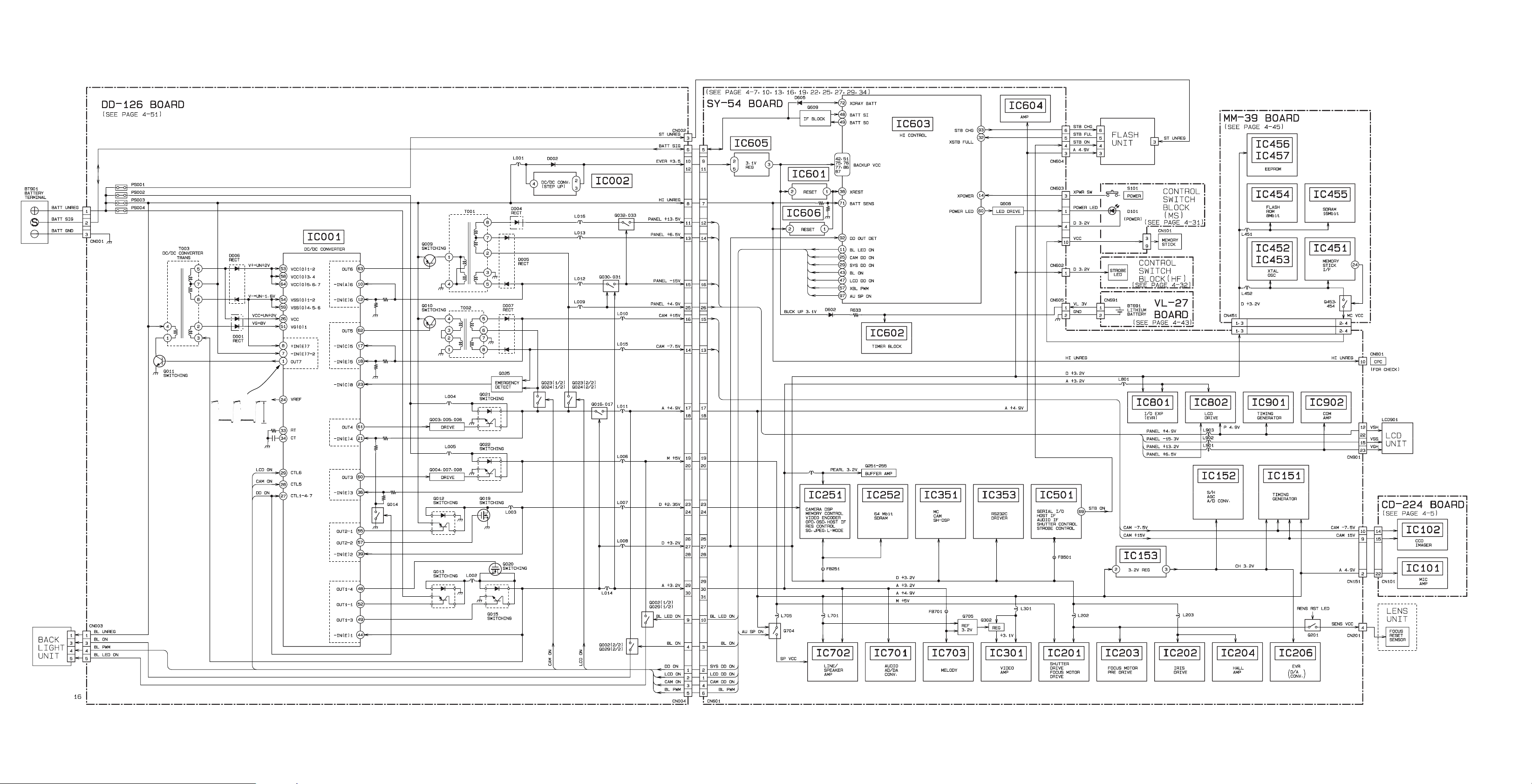
3-6. POWER BLOCK DIAGRAM
IC001 1 OUT7
500kHz
0.5µsec/div
0.2V/div
0.8Vp-p
3-16 3-17 3-18E
 Loading...