

Sony DPSV-55, DPSV-55-M Service manual
DPS-V55/V55M
SERVICE MANUAL
Photo: DSP-V55
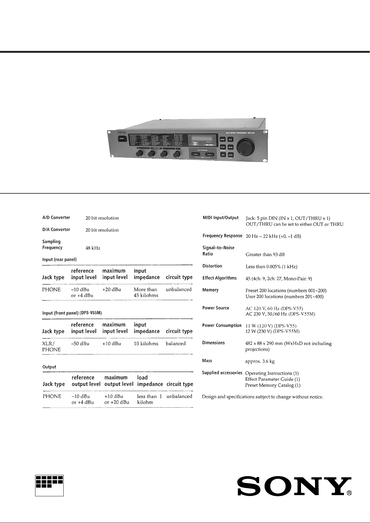
SPECIFICATIONS
US Model
Canadian Model
DPS-V55
AEP Model
UK Model
DPS-V55M
MICROFILM
MULTI-EFFECT PROCESSOR

TABLE OF CONTENTS
1. SERVICING NOTES............................................... 2
2. GENERAL ................................................................... 5
3. DISASSEMBLY ......................................................... 9
4. TEST MODE.............................................................. 11
5. DIAGRAMS................................................................. 13
5-1. Pr inted Wiring Board – MAIN Section – ...................... 15
5-2. Schematic Diagram – MAIN Section (1/3) – ................. 17
5-3. Schematic Diagram – MAIN Section (2/3) – ................. 19
5-4. Schematic Diagram – MAIN Section (3/3) – ................. 21
5-5. Pr inted Wiring Boards – PANEL Section – .................. 23
5-6. Schema tic Diagram – PANEL Section –....................... 25
5-7. IC Pin Function Description ........................................... 28
6. EXPLODED VIEWS ................................................ 32
7. ELECTRICAL PARTS LIST ............................... 34
SAFETY-RELATED COMPONENT WARNING!!
COMPONENTS IDENTIFIED BY MARK ! OR DOTTED
LINE WITH MARK ! ON THE SCHEMATIC DIA GRAMS
AND IN THE PARTS LIST ARE CRITICAL TO SAFE
OPERATION. REPLACE THESE COMPONENTS WITH
SONY PARTS WHOSE PART NUMBERS APPEAR AS
SHOWN IN THIS MANU AL OR IN SUPPLEMENTS PUBLISHED BY SONY.
ATTENTION AU COMPOSANT AYANT RAPPORT
À LA SÉCURITÉ!
LES COMPOSANTS IDENTIFIÉS P AR UNE MARQUE !
SUR LES DIAGRAMMES SCHÉMA TIQ UES ET LA LISTE
DES PIÈCES SONT CRITIQUES POUR LA SÉCURITÉ
DE FONCTIONNEMENT. NE REMPLACER CES COMPOSANTS QUE PAR DES PIÈCES SONY DONT LES
NUMÉROS SONT DONNÉS DANS CE MANUEL OU
DANS LES SUPPLÉMENTS PUBLIÉS PAR SONY.
– 2 –

SECTION 1
SERVICING NOTES
ROM VERSION CHECK
• This system have R OM version check function consequently key
set up of when power on.
(No need in open the main body)
1) Press three buttons [ENTER], [EXIT], and [POWER] simul-
taneously, in the power off.
2) Fluorescent indicator tube indicate ROM v ersion about 1 sec-
ond, and restart system.
Ver 1.00
UPDATING THE ROM (IC704) VERSION
The ROM version may be updated in order to fix the bugs or add
the functions. “All Initialize!!” is displayed and internal data are
automatically initialized, if the power is turned on after replacing
the ROM. In this case, the user preset data and system data cannot
be restored. Please notify the users of this matter.
If the same version ROM was replaced for repair, not for version
updating, the data are not initialized unless internal data are damaged.
Nevertheless, to avoid a trouble, it is recommended to save internal data using the Data Filer, etc.
The initial version of the ROM will be Ver.1.00 part No. 8-759499-74.
Note: Internal data mentioned above are all saved in the IC702 (CY6225LL)
when the power is turned off.
REPLACING THE BATTERY
The built-in battery must be replaced, if “Battery Low!” is displayed at the power ON. When the battery was used up completely, internally saved data (system data, user preset data, etc.)
are all cleared, and “Ext. RAM Error!” “All Initialize!!” are displayed at the power ON, then the data are initialized to the factory
setting automatically. In this case, the user preset data and system
data cannot be restored. Please notify the users of this matter.
Unless “Ext. RAM Error” “All Initialize!!” are displayed at the
power ON, internal data are still saved, and in this case, internal
data are kept unchanged if the battery is replaced while the power
is turned on.
To avoid a trouble, it is recommended to save internal data using
the Data Filer, etc.
This information is given to the users on page 19 of the Operation
Manual.
Flexible Circuit Board Repairing
• Keep the temperature of the soldering iron around 270 ˚C during
repairing.
• Do not touch the soldering iron on the same conductor of the
circuit board (within 3 times).
• Be careful not to apply force on the conductor when soldering or
unsoldering.
Notes on chip component replacement
• Never reuse a disconnected chip component.
• Notice that the minus side of a tantalum capacitor may be damaged by heat.
CAUTION
Danger of explosion if battery is incorrectly replaced.
Replace only with the same or equivalent type recommended by
the manufacturer.
Discard used batteries according to the manufacturer’ s instructions.
ADVARSEL!
Lithiumbatteri-Eksplosionsfare ved fejlagtig håndtering.
Udskiftning må kun ske med batteri
af samme fabrikat og type.
Levér det brugte batteri tilbage til leverandøren.
ADVARSEL
Eksplosjonsfare ved feilaktig skifte av batteri.
Benytt samme batteritype eller en tilsvarende type
anbefalt av apparatfabrikanten.
Brukte batterier kasseres i henhold til fabrikantens
instruksjoner.
VARNING
Explosionsfara vid felaktigt batteribyte.
Använd samma batterityp eller en likvärdig typ som
rekommenderas av apparattillverkaren.
Kassera använt batteri enligt gällande föreskrifter.
VAROITUS
Paristo voi räjähtää, jos se on virheellisesti asennettu.
V aihda paristo ainoastaan laite valmistajan suosittelemaan tyyppiin.
Hävitä käytetty paristo valmistajan ohjeiden mukaisesti.
– 3 –
SAFETY CHECK-OUT
After correcting the original service problem, perform the following safety check before releasing the set to the customer:
Check the antenna terminals, metal trim, “metallized” knobs,
screws, and all other exposed metal parts for AC leakage.
Check leakage as described below.
LEAKAGE TEST
The AC leakage from any exposed metal part to earth ground and
from all exposed metal parts to any exposed metal part having a
return to chassis, must not exceed 0.5 mA (500 microampers.).
Leakage current can be measured by any one of three methods.
1. A commercial leakage tester, such as the Simpson 229 or RCA
WT-540A. Follow the manufacturers’ instructions to use these
instruments.
2. A battery-operated AC milliammeter. The Data Precision 245
digital multimeter is suitable for this job.
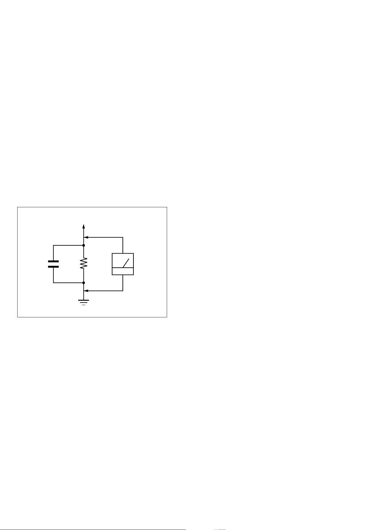
3. Measuring the voltage drop across a resistor by means of a V OM
or battery-operated A C voltmeter . The “limit” indication is 0.75
V, so analog meters must have an accurate low-voltage scale.
The Simpson 250 and Sanwa SH-63Trd are examples of a passive VOM that is suitable. Nearly all battery operated digital
multimeters that have a 2 V A C range are suitable. (See Fig. A)
To Exposed Metal
Parts on Set
1.5 k
0.15 µF
Fig. A. Using an AC voltmeter to check AC leakage.
Ω
Earth Ground
AC
voltmeter
(0.75 V)
– 4 –
SECTION 2
GENERAL
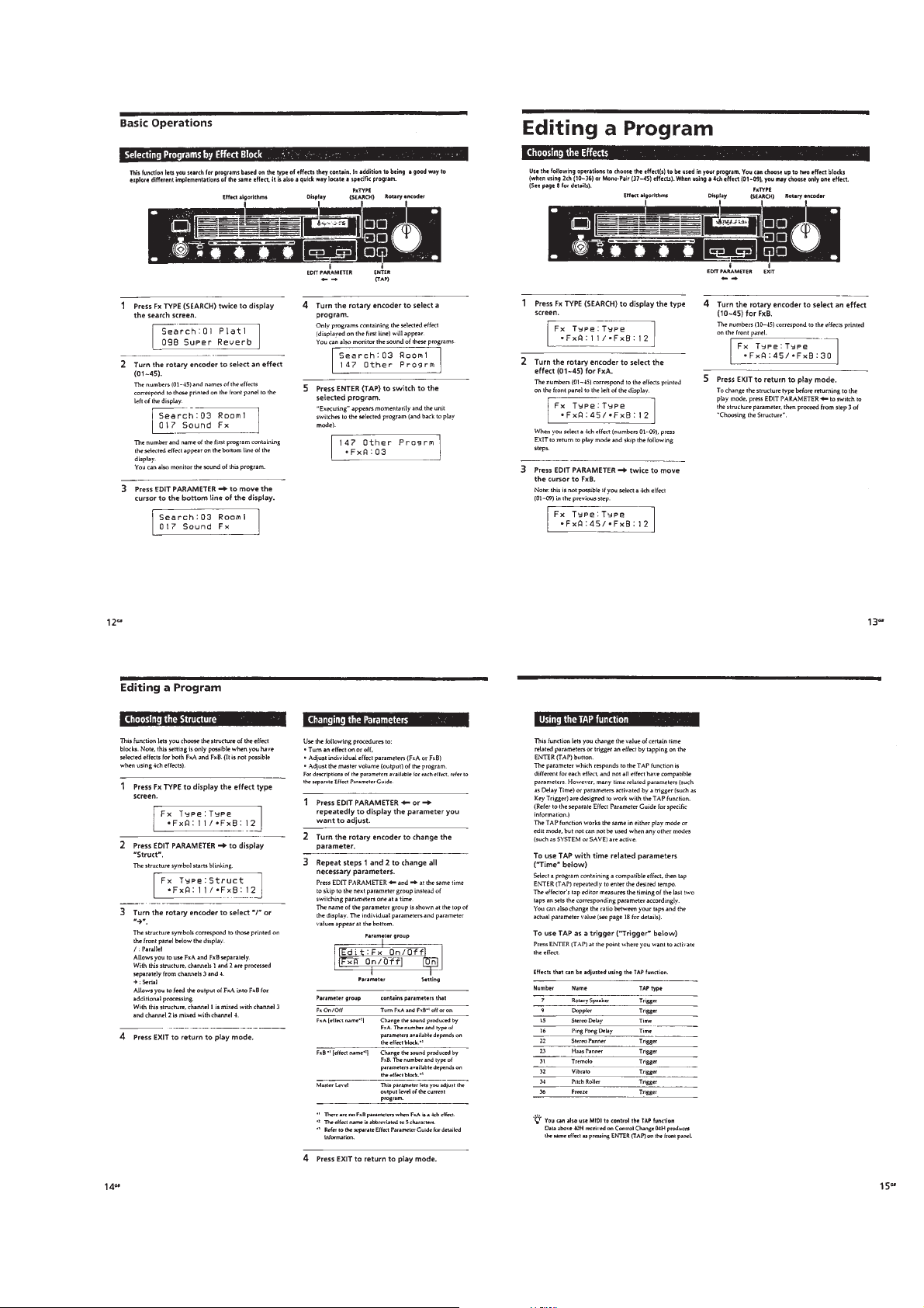
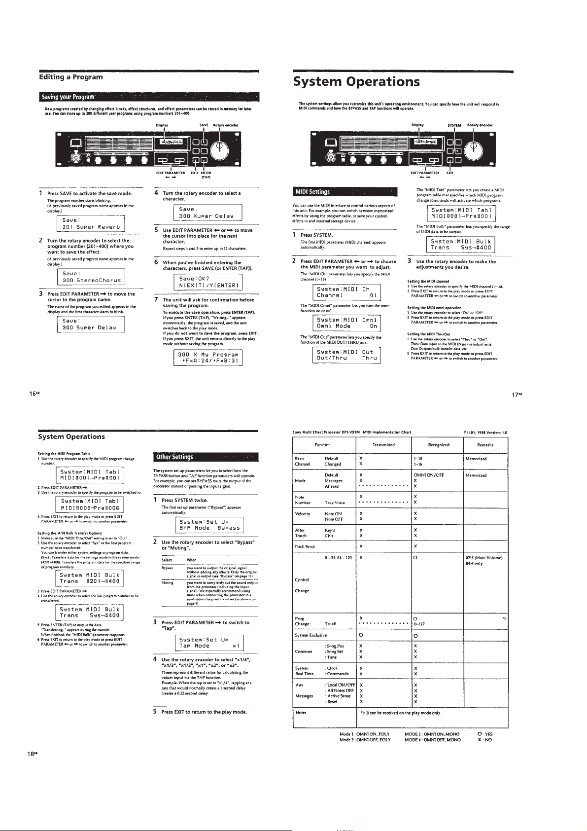
This section is extracted from
instruction manual.
– 5 –
– 6 –
– 7 –
– 8 –
SECTION 3
r
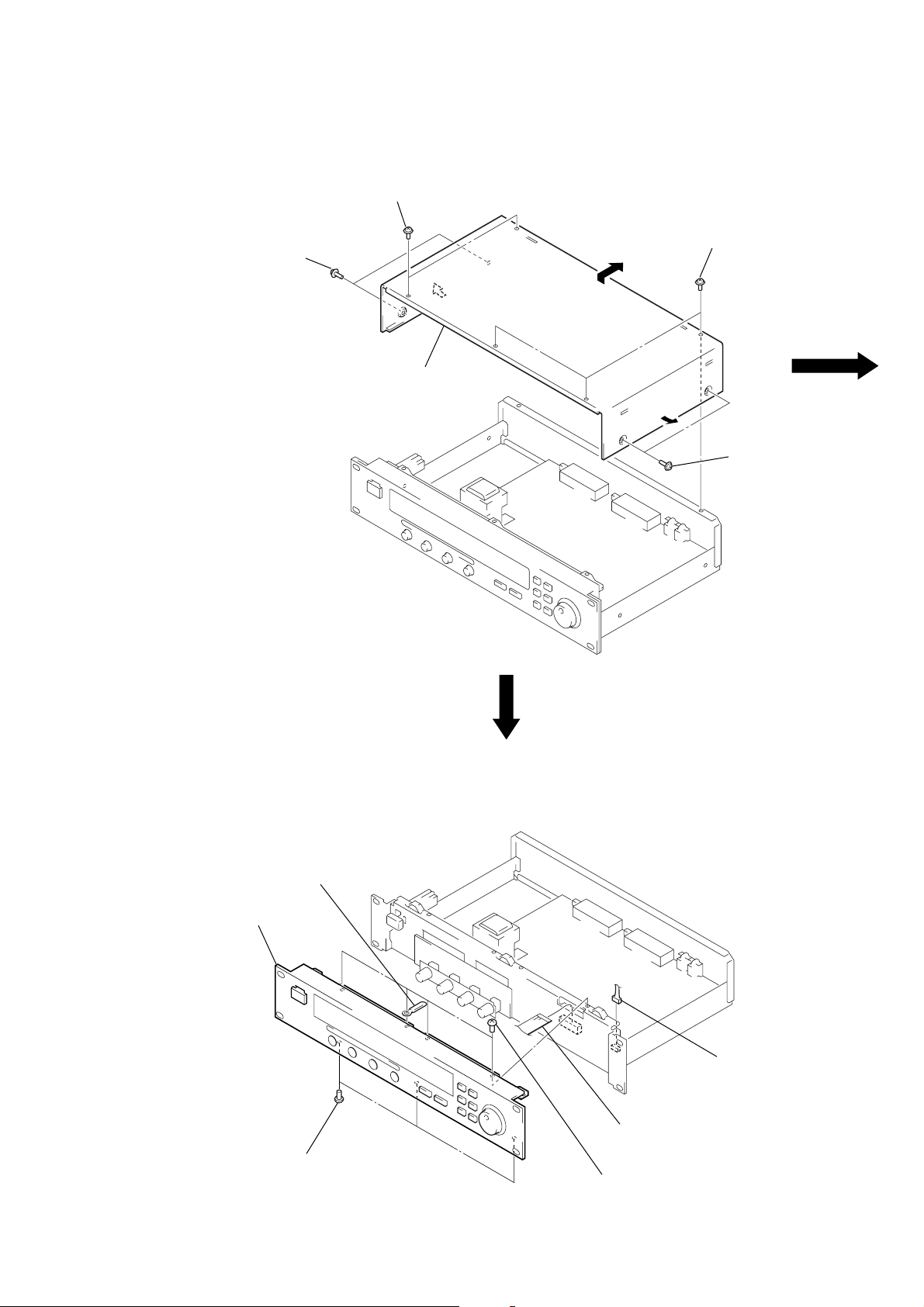
DISASSEMBLY
Note: Follow the disassembly procedure in the numerical order given.
CASE
1
two screws
(case 3 TP2)
2
two screws
(case 3 TP2)
3
case
1
three screws
(case 3 TP2)
2
two screws
(case 3 TP2)
FRONT PANEL ASS’Y
5
front panel ass’y
4
clamp
2
three screws
(BVTT3
1
connecto
(CN703)
1
flat wire (23 core)
3
four screws
(BVTT3
(CN702)
×
6)
×
6)
– 9 –
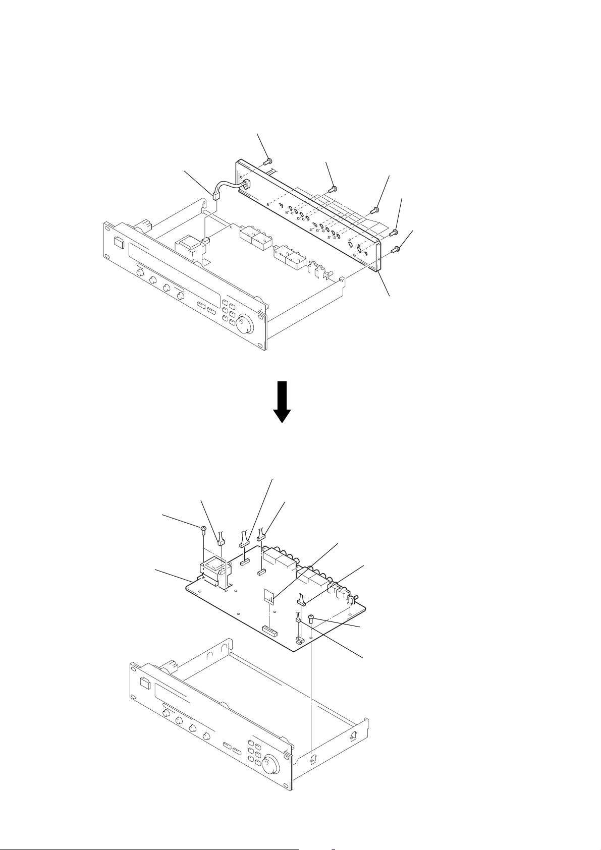
BACK PANEL
)
1
connector
(CN601)
3
screw
(BVTT3
×
6)
2
six screws
(BVTP3
×
10)
2
four lock screws
3
4
back panel
three screws
(BVTT3
3
×
screw
(BVTT3
6)
×
6
MAIN BOARD
2
two screws
(BVTT3
3
1
×
6)
MAIN board
connector
(CN602)
1
connector
(CN101)
1
connector
(CN301)
1
flat wire (23 core)
(CN702)
1
2
two screws
(BVTT3
1
connector
(CN701)
×
connector
(CN703)
6)
– 10 –
 Loading...