

Sony DKR-700, DKR-700P Instructions For Use Manual
Digital Still
Recor der
3-810-715-14(1)
Instructions for Use page 2(E)
Before operating the unit, please read this manual
thoroughly and retain it for future reference.
Mode d’emploi page 1(F)
Avant la mise en service de cet appareil, prière de lire
attentivement ce mode d’emploi que l’on conservera
pour toute référence ultérieure.
DKR-700/700P
1996 by Sony Corporation
Owner’s Record
R1.5m
The model and serial numbers are located at the rear.
Record the serial number in the space provided below.
Refer to these numbers whenever you call upon your Sony
dealer regarding this product.
Model No. DKR-700 Serial No.
WARNING
For DKR-700P
The following label is located on the top of the unit.
To prevent fire or shock hazard, do not expose the unit to
rain or moisture.
To avoid electrical shock, do not open the cabinet. Refer
servicing to qualified personnel only.
This symbol indicates type B equipment
classified in accordance with IEC Publication
601-1 Safety of medical electrical equipment.
(DKR-700 only)
This symbol indicates equipotential terminal
which brings the various parts of a system to the
same potential.
(DKR-700P only)
For the customers in the USA
This equipment has been tested and found to comply with the
limits for a Class A digital device, pursuant to Part 15 of the
FCC Rules. These limits are designed to provide reasonable
protection against harmful interference when the equipment
is operated in a commercial environment. This equipment
generates, uses, and can radiate radio frequency energy
and, if not installed and used in accordance with the
instruction manual, may cause harmful interference to radio
communications. Operation of this equipment in a residential
area is likely to cause harmful interference in which case the
user will be required to correct the interference at his own
expense.
You are cautioned that any changes or modifications not
expressly approved in this manual could void your authority
to operate this equipment.
This device requires shielded interface cables to comply with
FCC emission limits.
CAUTION
The use of optical instruments with this product will increase
eye hazard.
The following label is located inside the unit.
DANGER
INVISIBLE LASER RADIATION WHEN OPEN.
AVOID DIRECT EXPOSURE TO BEAM.
VORSICHT
UNSICHTBARE LASERSTRAHLUNG, WENN ABDECKUNG
GEÖFFNET. NICHT DEM STRAHL AUSSETZEN.
4-627-743-01
LITHIUM BATTERY
Should only be changed by technical personnel.
There is a risk of explosion in handled improperly.
Important safeguards/notices for use in the medical
environments
1. All the equipments connected to this unit shall be certified
according to Standard IEC601-1, IEC950, IEC65 or other
IEC/ISO Standards applicable to the equipments.
2. When this unit is used together with other equipment in the
patient area*, the equipment shall be either powered by an
isolation transformer or connected via an additional
protective earth terminal to system ground unless it is
certified according to Standard IEC601-1.
* Patient Area
3. The leakage current could increase when connected to
other equipment.
4. This unit generaters, uses, and can radiate frequency
energy. If it is not installed and used in accordance with
the instruction manual, it may cause interference to other
equipment. If this unit causes interference (which can be
determined by unplugging the power cord from the unit),
try these measures: Relocate the unit with respect to the
susceptible equipment. Plug this unit and the susceptible
equipment into different branch ciruits. Consult yor dealer.
CAUTION
Use of this product other than directed may result in injury.
2(E)

WARNING
When installing the unit, incorporate a readily accessible
disconnect device in the fixed wiring.
If a fault should occur during operation of the unit, operate
the disconnect device to switch the power supply off.
WARNING!
The DKR-700 is intended to be used for recording video
images obtained from video cameras and medical imaging
Table of Contents
systems, primarily for the purposes of image archival and
teaching/education. When any of the compressed modes
(FINE, NORMAL, QUICK2, QUICK1) are utilized, images
stored may not necessarily retain the full resolution and
image information as delivered by the originating source
modality.
This is because JPEG lossy compression is employed, and,
by definition, this type of compression discards certain
information which cannot ever be retrieved.
English
Overview............................................................... 4(E)
Features ...........................................................4(E)
Usage Example................................................5(E)
Usage Precautions ...........................................7(E)
Location and Function of Parts.......................... 8(E)
DKR-700/700P Main Unit ..............................8(E)
RM-C700 Remote Control Unit (Option) .....14(E)
Preparation ........................................................ 16(E)
Connections ...................................................16(E)
Setting the DIP Switch ..................................17(E)
MiniDiscs (MD Data Discs)..........................17(E)
Activating the DKR-700/700P and
Inserting/ Removing Discs..................18(E)
Initializing Discs ...........................................19(E)
Setting the Clock ...........................................19(E)
Checking the Setup/Operating Condition of
the DKR-700/700P..............................19(E)
Recording Images .............................................. 22(E)
Preparing to Record.......................................22(E)
Recording One Image at a Time — Step
Recording ............................................23(E)
Recording Images Automatically — Interval
Recording ............................................24(E)
Recording with a 1-Contact Foot Switch ......24(E)
Recording with the Optional FS-30 Foot
Switch..................................................25(E)
Playing or Searching for Images ...................... 26(E)
Preparing to Playback or Search ...................26(E)
Playing One Image at a Time — Step
Playback ..............................................27(E)
Playing Images Automatically — Interval
Playback ..............................................28(E)
Playing an Image by Its Image Number
— Direct Access Playback
(Using the RM-C700) .........................28(E)
Searching for an Image Using the Image
Index....................................................29(E)
Searching for an Image Using Information
Search List...........................................29(E)
Image Data Management
(Using the RM-C700) ................................. 32(E)
Keys Used to Input ID Numbers, Image
Names and Disc Names ......................32(E)
Setting/Changing the Disc Name ..................33(E)
Setting/Changing an ID Number...................33(E)
Setting/Changing an Image Name.................35(E)
Deleting Images.................................................. 37(E)
Erasing Images One at a Time ......................37(E)
Erasing All Images on the Disc.....................37(E)
Menu Operations ............................................... 38(E)
Menu Structure ..............................................38(E)
Buttons/Keys for Menu Operations...............39(E)
Structure and Usage of the Main Menu.........39(E)
Structure and Usage of the Source Setup
Menu ...................................................40(E)
Structure and Usage of the Capture/Rec Setup
Menu ...................................................41(E)
Structure and Usage of the Play Setup
Menu ...................................................43(E)
Structure and Usage of the Disp Setup
Menu ...................................................44(E)
Structure and Usage of the System Setup
Menu ...................................................45(E)
Structure and Usage of the User Setup
Menu ...................................................47(E)
Appendixes ......................................................... 49(E)
Specifications ................................................49(E)
Error Messages and Warning Messages........51(E)
Troubleshooting ............................................53(E)
Timing for Capturing an Image Using a Foot
Switch..................................................53(E)
3(E)

Overview
The DKR-700/700P Digital Still Recorder is a device
for recording still image to a MiniDisc (MD Data
Disc) and filing it for later playback.
Features
MiniDisc as a recording medium
The DKR-700/700P records images to a data MiniDisc
(MMD-140 MD Data Disc or equivalent: 140 Mbytes)
complying with the Sony picture MD format. This
magneto-optical recording medium not only boasts a
high degree of permanence and reliability, but also
reduces still image storage cost by recording up to
1000 images on a single disc.
Recording with digital compression
Using the latest digital technology, the DKR-700/700P
provides image quality better than 480 lines of
horizontal resolution. The DKR-700/700P employs
widely-used JPEG compression method and TIFF
format for uncompressed images, making it possible to
examine images using commonly available software.
Rich search functionality
The DKR-700/700P allows a desired image to be
found quickly. Searches may be performed on image
information such as the image number, ID number,
image name, or date, and an image may also be located
via image indexes (25 thumbnail images per index).
Setup using menus
The menus allow basic selections such as video input/
output connectors and image recording quality, as well
as the setup of recording and playback modes, status/
setup information display, and system control.
Various video input/output connectors
The DKR-700/700P is equipped with RGB, composite,
and S video input/output connectors. A wide variety
of input sources may be selected, from common
sources such as video cameras and VCRs to LaserDisc
players and medical imaging equipment. The DKR700/700P may be connected to output devices such as
video monitors, video projectors, and video printers.
Selectable image quality
When recording, one of five image quality modes
(uncompressed, fine, normal, quick 2, and quick 1) can
be selected. This allows the DKR-700/700P to be used
in a wide variety of applications, ranging from the
medical field, which requires high image quality, to
filing systems which emphasize the storage of large
numbers of images and must be quickly searchable.
Simultaneous recording of image
information
When recording an image, the date (year, month, day,
hour, minute, and second) and an image number are
automatically recorded or updated. With the
connection of the optional RM-C700 Remote Control
Unit or a computer, it becomes possible to attach an
image ID number (up to 15 digits) and an image name
(up to 15 alphanumeric characters).
External control functionality
The DKR-700/700P is equipped with an RS-232C
interface connector and a SCSI interface connector.
Besides the optional RM-C700 Remote Control Unit
or a computer, an optional 3-contact foot switch FS-30
or a 1-contact foot switch may be connected, allowing
external control of the DKR-700/700P.
Record and playback modes selection
according to purpose
Images may be recorded and played back one at a time
(step recording/playback), or may be recorded or
played back in order (interval recording/playback).
4(E)
Synchronization with imaging equipment
medical use) Video Camera, using the slow electronic
shutter feature enables clear, sharp recording even of
Since the DKR-700/700P can generate a flash trigger
signal when an image is recorded, images may be
low-illumination images such as those from
fluorescence microscopes.
acquired in synchronization with a flash. When paired
with the Sony DXC-950 series (DXC-970MD for
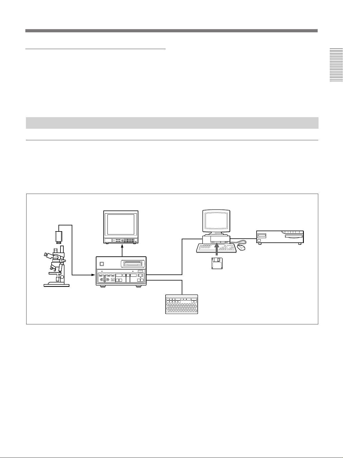
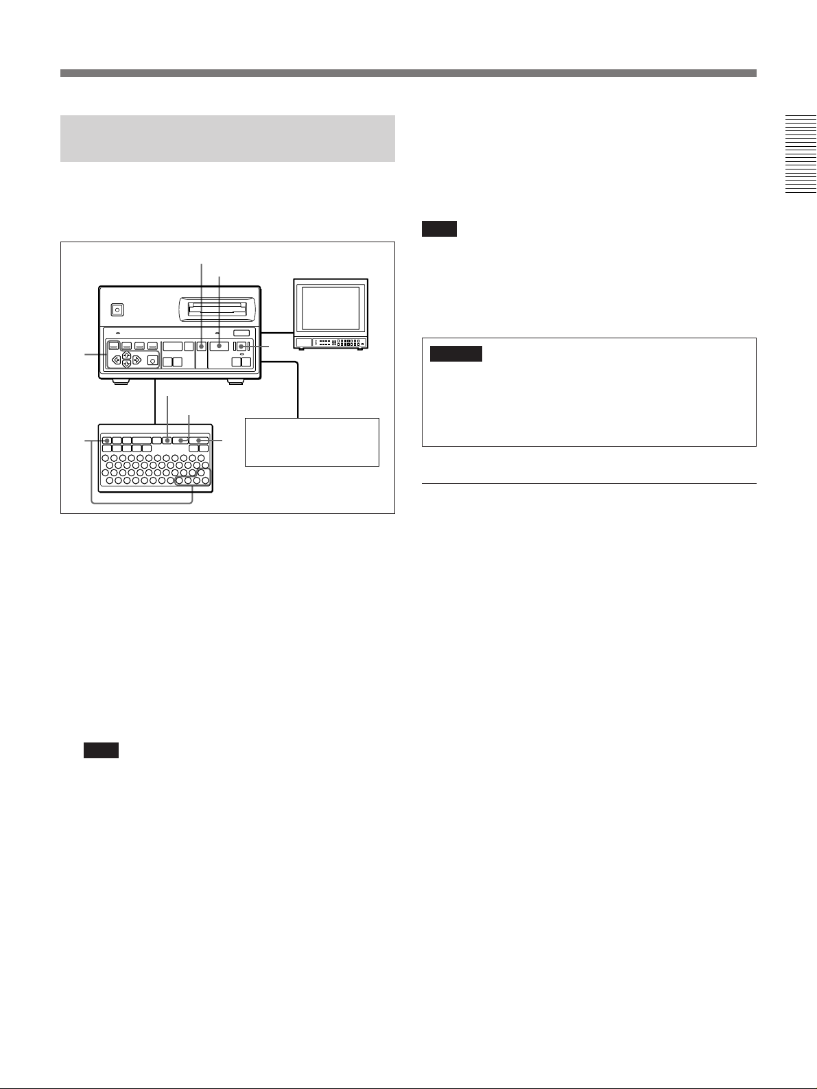
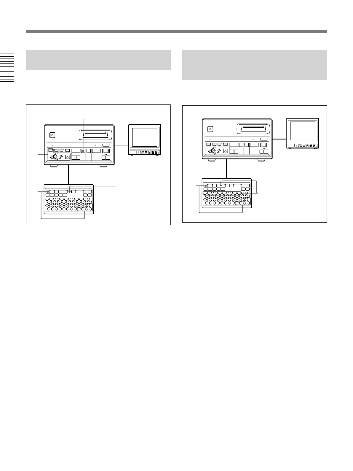
Usage Example
Image filing system for medical or industrial measurement applications
The DKR-700/700P may be coupled with medical
instruments or with factory measurement equipment to
form an image filing system. By using the supplied
DKR-700 Plug-In Software (running under Microsoft
Video monitor
Video Camera
Microscope
DKR-700/700P
Windows1) or MacOS2)), image data can be transferred
to a computer connected to the DKR-700/700P via a
SCSI interface.
Computer
SCSI
UP-5500 series
Video Printer
SCSI
DKR-700 Plug-In Software
(supplied)
RM-C700 Remote Control Unit
(option)
..........................................................................................................................................................................................................
1) Windows is a trademark of Microsoft Corporation.
2) On the PowerBook, the Plug-In Software does not
function properly.
5(E)

Overview
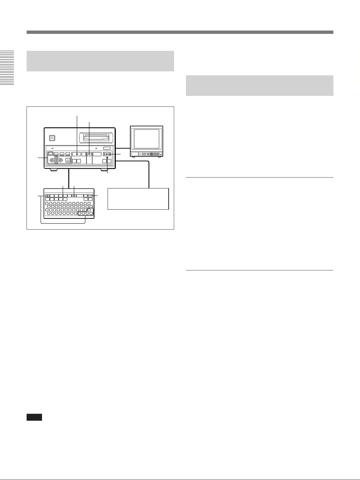
Computer-based image processing system
By using the supplied DKR-700 Plug-In Software
1)
(running under Microsoft Windows or MacOS
),
image data may be exchanged with a computer
Video Camera
Copy stand
DKR-700/700P
Photo proofing system
connected to the DKR-700/700P via a SCSI interface.
Images can be transferred from the DKR-700/700P to
a computer for processing and use in CG still
production.
Video monitor
SCSI
RM-C700
Remote Control
Unit (option)
Computer
DKR-700 Plug-In
Software (supplied)
When taking photographs with a film camera, the same
images may be captured simultaneously using the
DXC-950 series (DXC-970MD for medical use) Video
Camera and stored with the DKR-700/700P to allow
proofing of the images before the photographs have
been developed, printed, or enlarged. The image can
Photo flash
slave unit
Flash
Trigger signal
Video Camera
Flash unit
Film camera
be captured via automatic recording, based on the
timing of a trigger signal from the video camera, or the
timing of the capture can be controlled by a flash
signal generated by the DKR-700/700P. Besides
proofing in a photo studio, the same system can also be
used in industrial or medical inspection photography.
Video monitor
UP-1000 series
DKR-700/700P
Video Printer
..........................................................................................................................................................................................................
1) On the PowerBook, the Plug-In Software does not
function properly.
6(E)

Usage Precautions
Operation and storage locations
Avoid operation or storage in any of the following
places.
•Location subject to extremes of temperature
(operating temperature range 5˚C to 35˚C (41˚F to
95˚F))
•Location subject to direct sunlight for long periods, or
close to heating appliances (Note that the interior of a
car left in summer with the windows closed can
exceed 50˚C (122˚F).)
•Damp or dusty places
•Location subject to severe vibrations
•Location near equipment generating strong
electromagnetic emissions
•Location near transmitting stations generating strong
radio waves
Operate the unit in a horizontal position
This unit is designed to be operated in a horizontal
position. Do not operate it on its side, or tilted through
an excessive angle (exceeding 20˚).
Avoid violent impacts
Dropping the unit, or otherwise imparting a violent
shock to it, is likely to cause it to malfunction.
Do not obstruct ventilation openings
To prevent the unit from overheating, do not obstruct
ventilation openings, by for example wrapping the unit
in a cloth while it is in operation.
Regular check
There is no need for regular checks.
Cleaning
If the casing or panel is dirty, wipe it gently with a soft
dry cloth. In the event of extreme dirt, use a cloth
steeped in a neutral detergent to remove the dirt, then
wipe with a dry cloth. Applying alcohol, thinners,
insecticides, or other volatile solvents may result in
deforming the casing or damaging the finish.
Shipping
•Always remove the disc before shipping the unit.
•Pack the unit in its original carton or equivalent
packing, and take care not to impart violent shocks in
transit.
7(E)

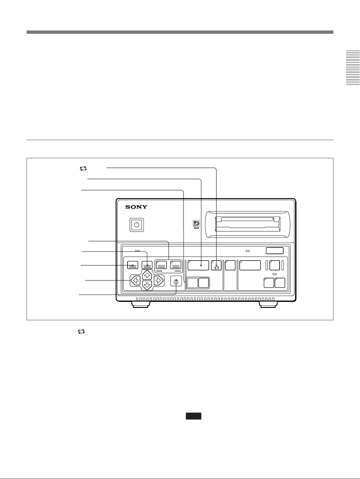
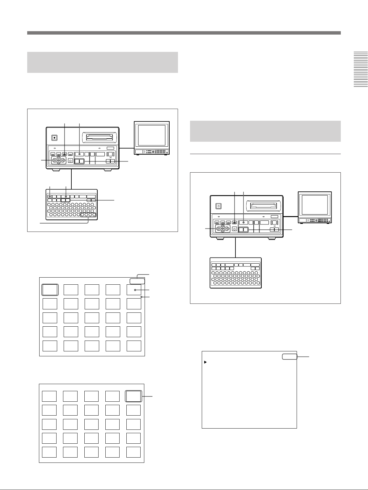
Location and Function of Parts
DKR-700/700P Main Unit
Power supply and data recording/deletion operations (front panel)
1 POWER u switch and indicator
DIGITAL STILL RECORDER
POWER
POWER
BUSY
EJECT
6
2 Disc slot
3 BUSY indicator
4 EJECT 6 button
AUTO
MENU DISP IMAGE LIST
SEARCH
EXEC
PLAY
(
+
-- --
PLAY
SOURCE
…
1 POWER u switch and indicator
Pressing this switch once turns on power to the unit,
and pressing it again turns the unit off. When the
power is on, the indicator will light up. If the BUSY
indicator is lit or blinking when you press the POWER
switch to power off, the unit powers off after internal
processing is completed.
2 Disc slot
For inserting discs.
3 BUSY indicator
When some operation is being performed on the disc,
or when some data remains on the DKR-700/700P’s
memory, this indicator will be lit or will blink. When
the indicator is lit, all buttons except the EJECT button
4 will have no effect.
Caution
Do not disconnect the AC power cord from the
outlet while the BUSY indicator is lit or blinking. If
the power is disconnected while the disc is in
operation, data stored on the disc may be lost or
damaged.
8(E)
CAPTURE REC
Xr
ERASE
AUTO
ALL
ERASE
INIT
5 REC r button
6 AUTO indicator
7 ALL ERASE/INIT button
8 ERASE button
9 CAPTURE X button
!º SOURCE … button
4 EJECT 6 button
Pressing this button will eject the disc.
5 REC r (record) button
When the button is pressed, it will light, and recording
will begin. When recording is complete, it will go out.
6 AUTO (automatic record) indicator
When an automatic record is being performed (using
the menus), this indicator will light.
For more information on automatic recording, see
“Recording Images Automatically — Interval Recording”
on page 24(E).
7 ALL ERASE/INIT button
This button is used to erase all images recorded on a
disc. It is also used to initialize discs.
Insert a disc which is to be erased, and press the
button. The button will begin to blink. When the
button is pressed a second time while it is blinking, it
will light steadily, and the all erasing will begin.
When inserting a disc which is not initialized or
initialized to a format incompatible with this unit, the
button will begin to blink automatically. To initialize
the disc press the button while it is blinking.
8 ERASE button
When this button is pressed while using the PLAY
button to play back an image, the button will blink.
When the button is pressed again, it will light and the
image currently being played will be erased. When
erasing is complete, it will go out.
9 CAPTURE X button
When this button is pressed, it will light, and the video
signal being received will be captured in the DKR-
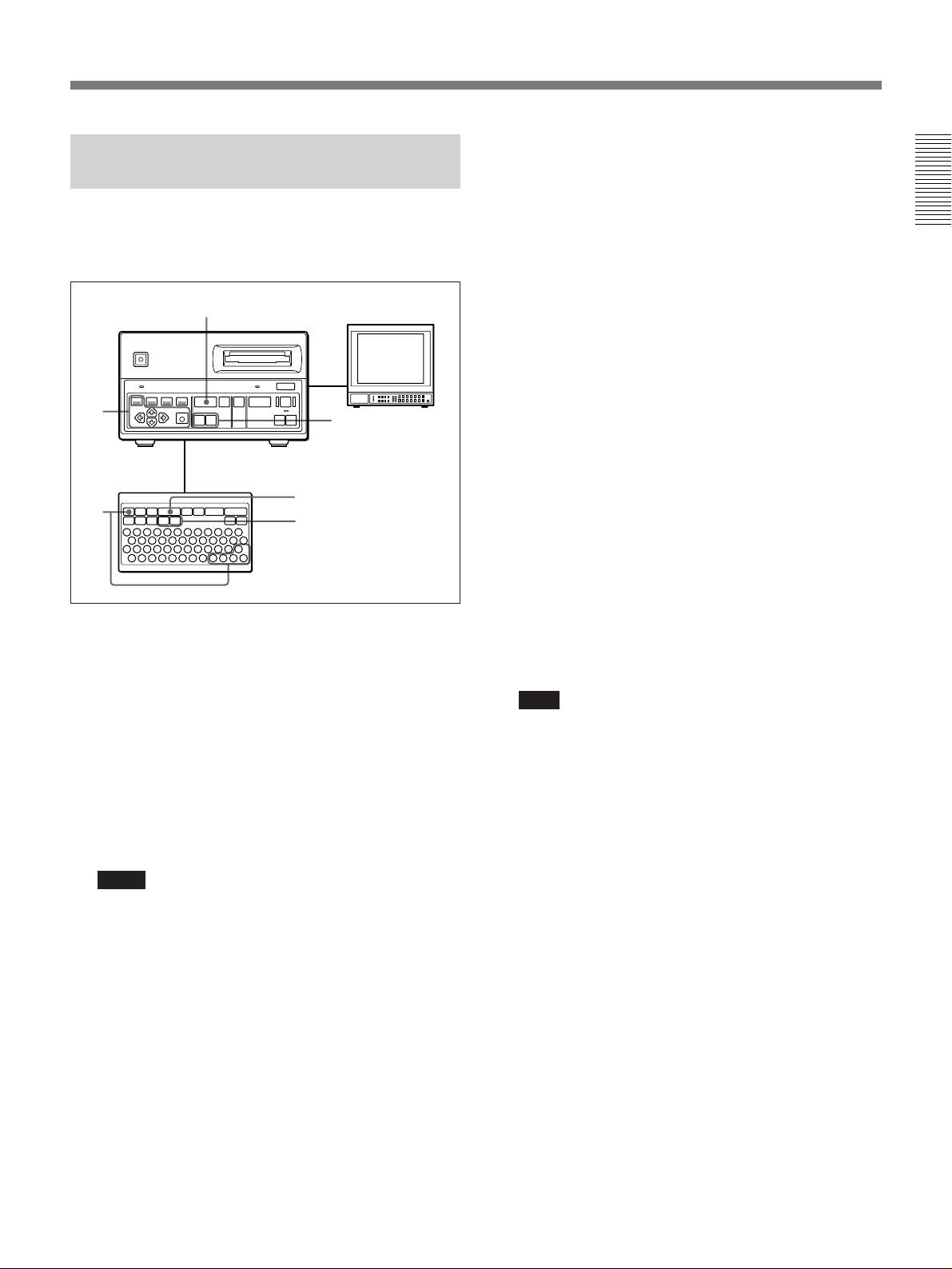
Menu, image playback, and search (front panel)
1 AUTO PLAY button
2 PLAY ( button
3 [+]/[–] buttons
POWER
700/700P’s memory. The video signal will
simultaneously be output from the video output
connector.
!º SOURCE … button
When this button is pressed it will light, and the video
signal being received will be output from the video
output connector.
DIGITAL STILL RECORDER
4 SEARCH buttons
5 DISP button
6 MENU button
7 Cursor buttons
8 EXEC button
1 AUTO PLAY
button
POWER
MENU DISP IMAGE LIST
SEARCH
When this button is pressed it will light, and all images
stored on disc will be played back in turn. The
playback direction and the intervals between each
image depend on parameters set in the menus.
2 PLAY ( button
When this button is pressed it will light, and one image
stored on the disc will be played back. When this
button is pressed after selecting a desired image using
the search display (see SEARCH buttons 4), that
image will be the one played. Either a main image or a
“quick access” image may be played, according to
what is selected in the menus.
EXEC
BUSY
AUTO
PLAY
PLAY
(
+
-- --
SOURCE
…
CAPTURE REC
Xr
ERASE
EJECT
6
AUTO
ALL
ERASE
INIT
3 [+]/[–] buttons
When the PLAY button 2 is lit, pressing the [+] or [–]
button will cause a different image to be played back.
The search images and search information lists are
changed using the search display (see SEARCH
buttons 4).
[+] button: Each time this button is pressed, a image
with higher image number will be displayed.
[–] button: Each time this button is pressed, a image
with lower image number will be displayed.
Note
If there are images already recorded on the disc with a
different type of device, the image numbers may in
some cases not be consecutive.
9(E)

Location and Function of Parts
4 SEARCH buttons
When one of the buttons is pressed, it will light, and a
search display will appear on the screen. To search by
image, press the IMAGE button. To search by image
information, press the LIST button.
When the IMAGE button is pressed: Images stored
on disc will be displayed as thumbnails (25
images on screen at once). When an image is
selected using the cursor buttons 7 and the
PLAY button 2 is pressed, that image will be
displayed on screen.
When the LIST button is pressed: Information
about images stored on disc (image number,
image name, ID number, date) will be displayed
as a list. When an image is selected using the
cursor buttons 7 and the PLAY button 2 is
pressed, that image will be displayed on screen.
5 DISP (display) button
When this button is pressed, the DKR-700/700P’s
setup and status information will be superimposed on
the screen. The items to be displayed may be set using
the menus. When the button is pressed again, the
information display will disappear.
6 MENU button
When this button is pressed, the menu display will
appear on the screen. When the button is pressed
again, the menu display will disappear.
7 Cursor buttons
In the menu display (see MENU button 6), these
buttons are used to select menu items (the
˘
and
≥
buttons) and to change settings and conditions (the
and ÷ buttons). In the search display (see SEARCH
buttons 4), the cursor buttons are used to select a
desired image.
8 EXEC (execute) button
This button is used to go from the main menu to a
setup menu, and to confirm changes made to settings
in the menu. Besides menu operation, this button is
used to record the data on the DKR-700/700P’s
memory. (If some data remains on the memory, the
BUSY indicator will blink.)
¿
10(E)
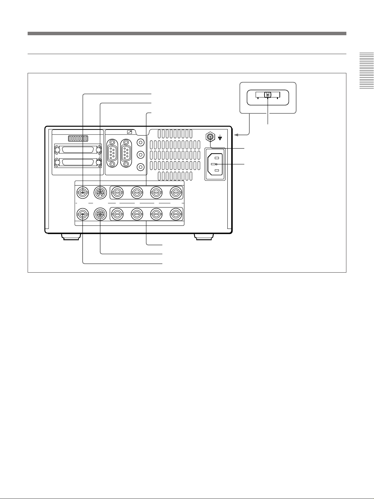
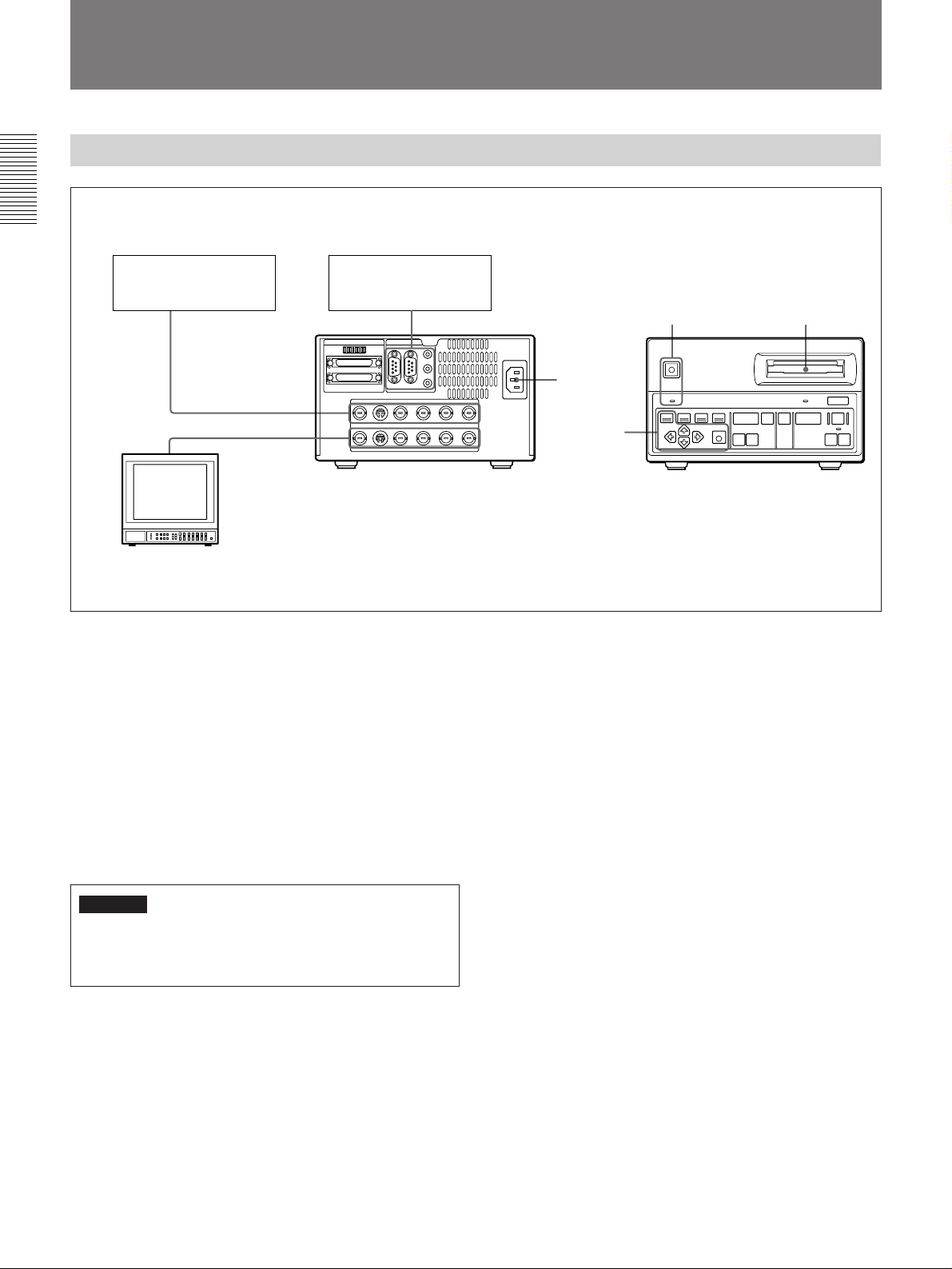
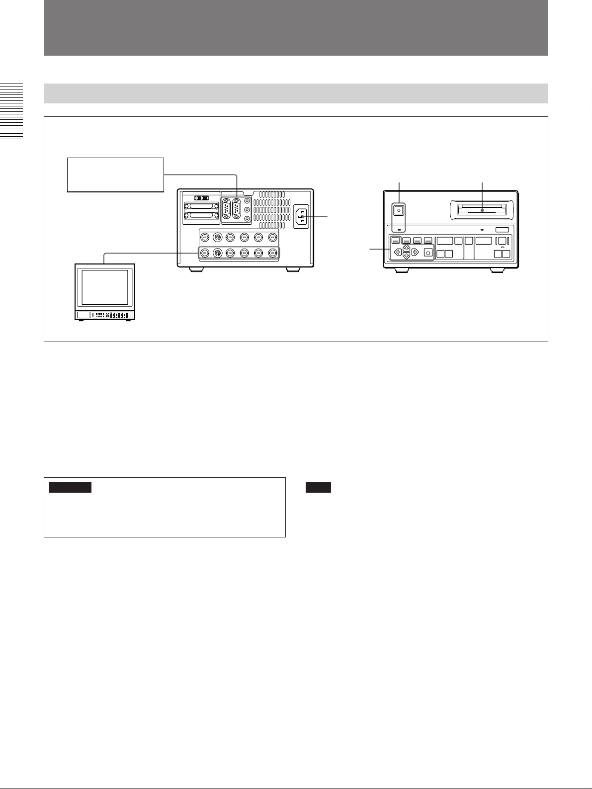
Power supply and video input/output connectors (rear panel)
1 VIDEO INPUT connector
2 S-VIDEO INPUT connector
3 RGB/SYNC INPUT connectors
SCSI REMOTE
ID
RS-232C FS1
INPUT
FS2
EX-CTL
FLASH
…
AC IN
⁄
220V 230V 240V
4 Voltage 220V/230V/240V
selector (DKR-700P only)
5 1 (equipotential) terminal
(DKR-700P only)
6 ⁄ AC IN connector
VIDEO S-VIDEO
R G B SYNC
OUTPUT
Ú
7 RGB/SYNC OUTPUT connectors
8 S-VIDEO OUTPUT connector
9 VIDEO OUTPUT connector
1 VIDEO INPUT connector (BNC-type)
Connect to the video output connector of a video
camera, VCR, etc.
For the electrical specification of this connector, see page
49(E).
2 S-VIDEO INPUT connector (mini-DIN 4-pin)
Connect to the S video output connector of a video
camera, VCR, etc.
For the electrical specification of this connector, see page
49(E).
Illustration: DKR-700P
3 RGB/SYNC INPUT connectors (BNC-type)
Connect to the RGB and SYNC output connectors of a
video camera, etc.
For the electrical specification of these connectors, see page
49(E).
4 Voltage 220V/230V/240V selector (DKR-700P
only)
Set the position which meets voltage in the mains line
prior to the operation of the unit.
Otherwise the unit may be damaged.
5 1 (equipotential) terminal (DKR-700P only)
Connect to the system ground as required.
11(E)

Location and Function of Parts
6 ⁄ AC IN (inlet) connector (3-pin)
Connect to the AC power source, using the supplied
AC power cord.
7 RGB/SYNC OUTPUT connectors (BNC-type)
Connect to the RGB and SYNC input connectors of a
video monitor, video printer, etc.
For the electrical specification of these connectors, see page
49(E).
8 S-VIDEO OUTPUT connector (mini-DIN 4-pin)
Connect to the S video input connector of a video
monitor, etc.
For the electrical specification of this connector, see page
49(E).
9 VIDEO OUTPUT connector (BNC-type)
Connect to the video input connector of a video
monitor, VCR, etc.
For the electrical specification of this connector, see page
49(E).
12(E)

Remote connectors (rear panel)
SCSI REMOTE
ID
RS-232C FS1
INPUT
1 DIP switch
2 SCSI connectors
3 RS-232C connector
4 FS1 connector
FS2
EX-CTL
FLASH
…
AC IN
⁄
5 FS2 connector
6 EX-CTL connector
7 FLASH connector
VIDEO S-VIDEO
R G B SYNC
OUTPUT
1 DIP switch
Used to set the SCSI-ID and operation mode.
2 SCSI connectors (50-pin, half-pitch)
Used to connect to a computer to exchange image data.
For the electrical specification of these connectors, see page
50(E).
3 RS-232C connector (D-sub 9-pin)
Used to provide external control of the DKR-700/
700P, by connection to the optional RM-C700 Remote
Control Unit or to a computer. Select which of the two
is connected using the menus.
For the electrical specification of this connector, see page
49(E).
Ú
Illustration: DKR-700P
6 EX-CTL (external control) connector (minijack)
Used to control external devices from the DKR-700/
700P.
For the electrical specification of this connector, see page
50(E).
7 FLASH connector (mini-jack)
Used to connect to the external trigger connector of a
flash unit.
For the electrical specification of this connector, see page
50(E).
4 FS1 connector (D-sub 9-pin)
Used to connect an optional FS-30 Foot Switch.
5 FS2 connector (stereo mini-jack)
Used to connect a 1-contact foot switch.
For the electrical specification of this connector, see page
50(E).
13(E)
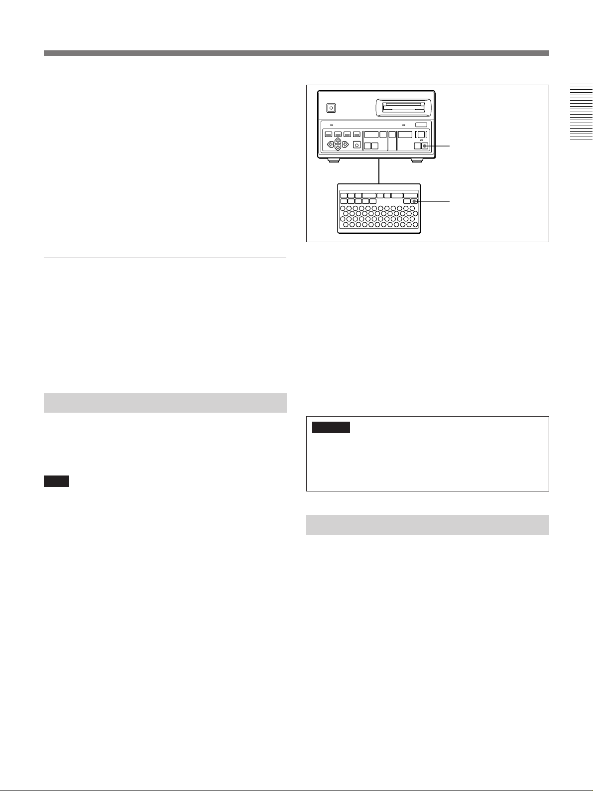
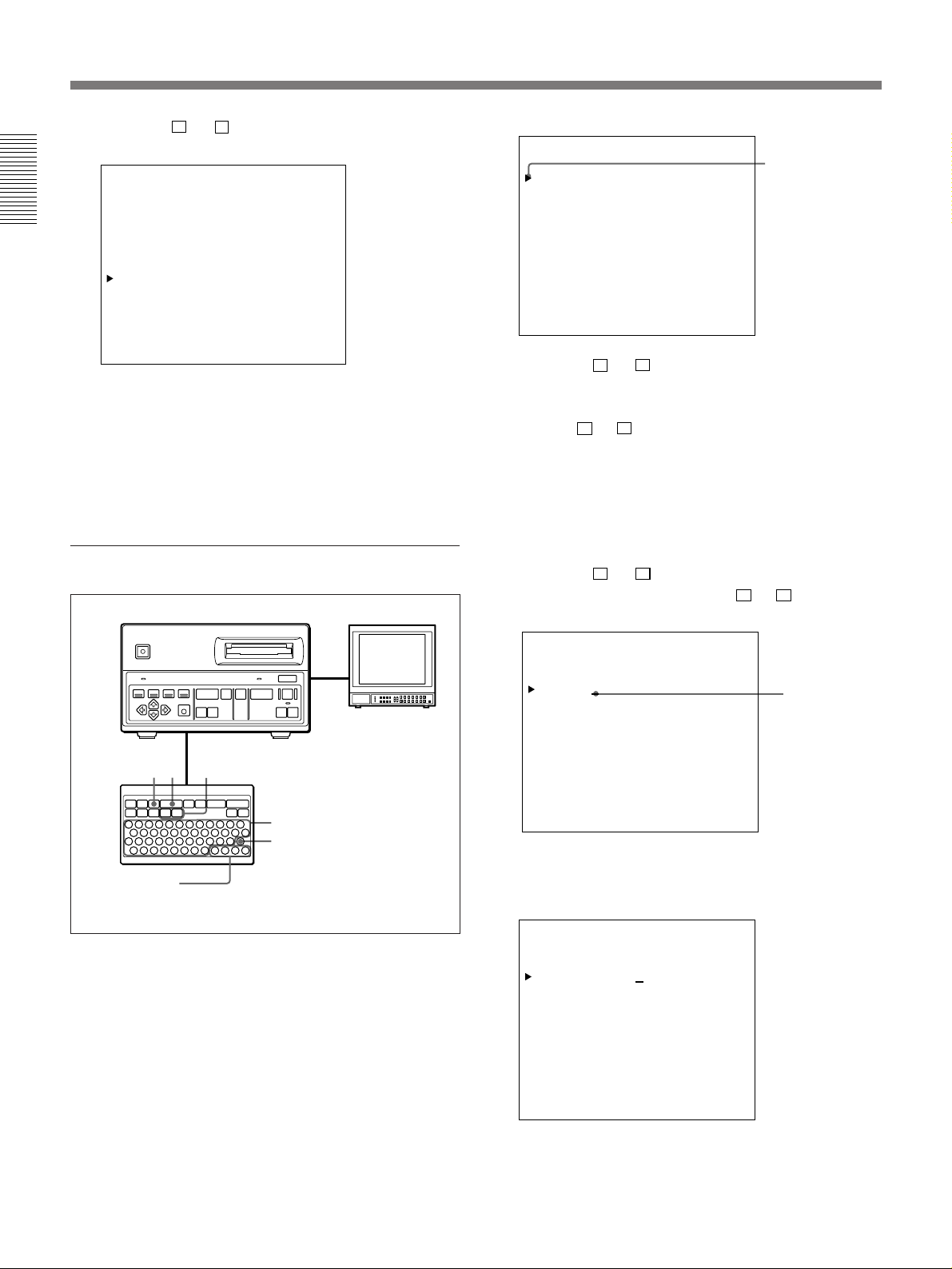
Location and Function of Parts
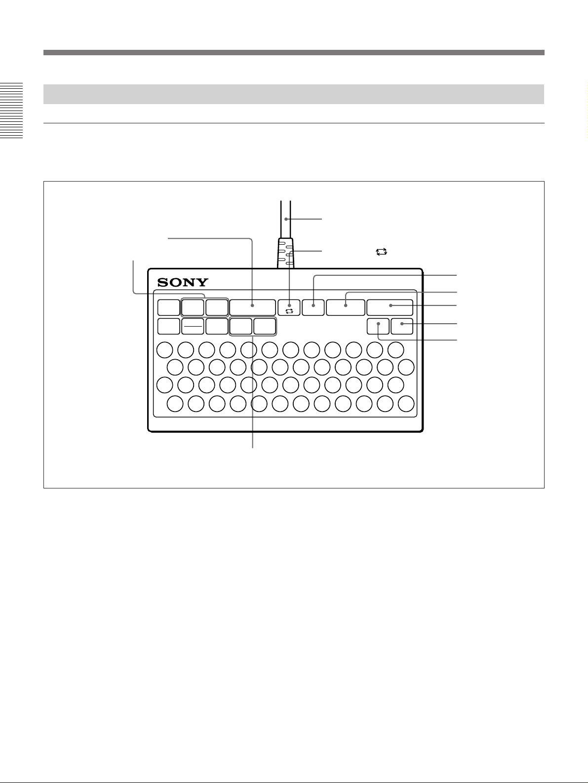
RM-C700 Remote Control Unit (Option)
Record/play operations
For keys, see the descriptions of corresponding buttons on
the DKR-700/700P.
PLAY ( key
Search keys
Connection cable: Attach to the RS-232C connector on
the rear panel of the DKR-700/700P.
AUTO PLAY key
AUTOPLAY
SOURCE
…
CAPTURE
X
+
--
PLAY
(
MENU IMAGE
DISP
!
2@3#4$5%6"7&8*9(0
1
DISC
NAME
LIST
ID NO
QWERT Y U I O P
SHIFT
ASDFGHJKL
SPC
ZXCVBNM
N
[+]/[–] keys
ERASE
)
n
RM-C700
REC
r
ERASE
_
-
/
+
=
DEL EXE
N
ALL
INIT
:
SOURCE … key
CAPTURE X key
REC r (record) key
ALL ERASE/INIT key
ERASE key
.
,
n
14(E)
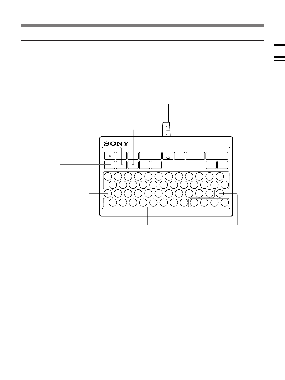
Menu/character entry operations
For the MENU, DISP, cursor, and EXE keys, see the
descriptions of corresponding buttons on the DKR-700/
700P.
For more information on character entry keys, see “Keys
Used to Input ID Numbers, Image Names and Disc
Names” on page 32(E).
ID NO (ID number) key: When
DISC (disc name)/NAME (image name)
key: When this key is pressed, the
image name input display will appear
on the screen.
If pressed while holding down the
SHIFT key, the disc name input
display will appear.
this key is pressed, the ID
number input display will
appear on the screen.
RM-C700
MENU key
DISP (display) key
SHIFT key: Holding down this button
while pressing the DISC/NAME
button will enable the disc name
function of that button. It is also
used to enter symbols and capital
letters.
AUTOPLAY
SOURCE
…
CAPTURE
X
+
--
PLAY
(
MENU IMAGE
DISP
!
1
LIST
DISC
ID NO
NAME
2@3#4$5%6"7&8*9(0
QWERT Y U I O P
SHIFT
ASDFGHJKL
SPC
ZXCVBNM
N
Character entry keys: Alphanumeric keys
are used to enter ID numbers, image
names, etc.
REC
r
ALL
ERASE
ERASE
INIT
_
)
n
-
/
+
=
DEL EXE
N
:
.
,
n
Cursor keys EXE (execute) key
15(E)
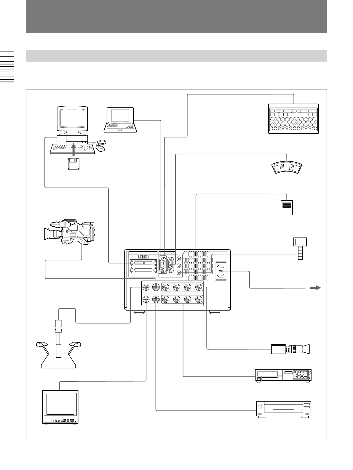
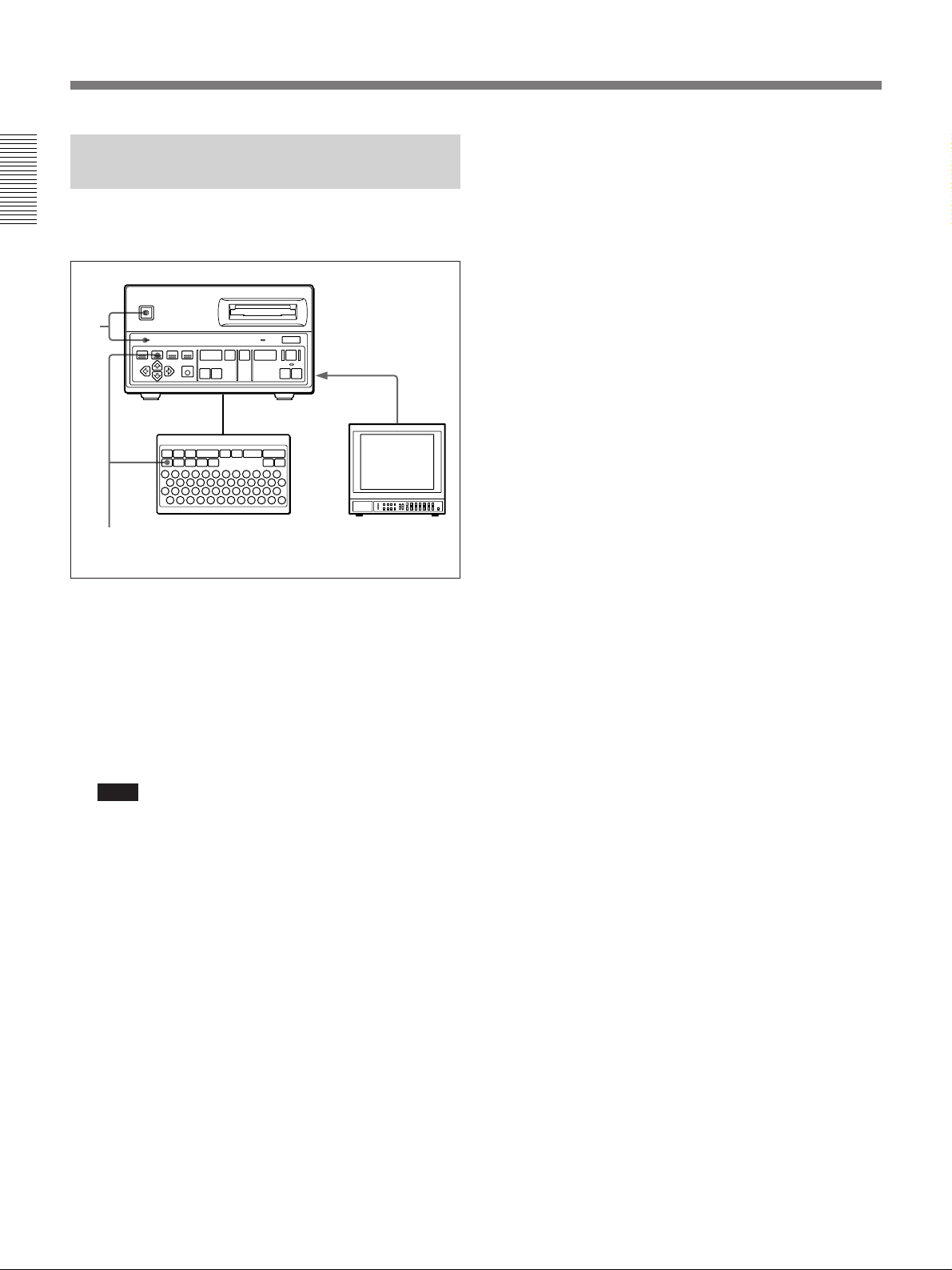
Preparation
Connections
Connect equipment required to the DKR-700/700P as
shown in the figure below.
SCSI
connector
Composite
video
output
connector
Host computer
Notebook-size personal
computer
DKR-700 Plug-In
Software (supplied)
KB-SPC06
SCSI Cable
(SANWA supply)
b)
Camcorder
S video
output
connector
S video cable (not supplied)
S-VIDEO
INPUT
75-ohm coaxial
cable (BNC)
(not supplied)
SCSI
VIDEO
INPUT
RS-232C
connector
SMF-3036C
RS-232C
b)
Cable
RS-232C
SCSI REMOTE
VIDEO S-VIDEO
VIDEO
OUTPUT
ID
RS-232C FS1
INPUT
R G B SYNC
OUTPUT
S-VIDEO
OUTPUT
FS1 FS2
FS2
EX-CTL
FLASH
…
Ú
RGB/
SYNC
OUTPUT
FLASH
AC IN
⁄
⁄ AC IN
DKR-700/700P
Digital Still Recorder
RGB/SYNC
INPUT
75-ohm coaxial
cable (BNC) ×4
(not supplied)
AC power cord
(supplied)
RGB/SYNC
output
connectors
RM-C700 Remote
Control Unit (option)
FS-30 Foot Switch
(option)
1-contact foot switch
Flash unit
a)
Video camera
To AC
power
source
16(E)
Copy stand
75-ohm coaxial cable
(BNC) (not supplied)
Composite video input connector
a) Illustration: DKR-700
Video monitor
b) For details of the SCSI cable and RS-232C cable which can be used with the DKR-700/700P,
S video cable
(not supplied)
contact your authorized Sony dealer.
75-ohm coaxial
cable (BNC) ×4
(not supplied)
RGB/SYNC
input
connectors
Video printer
S video input
connector
VCR
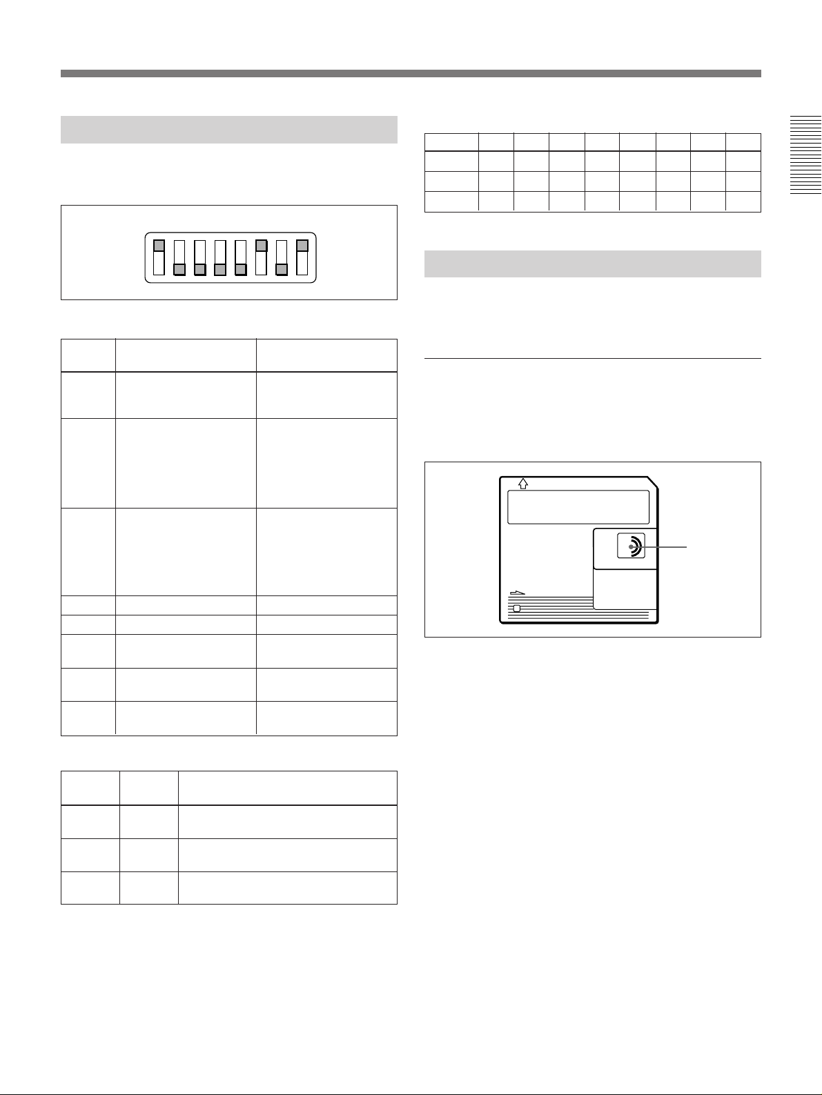
Setting the DIP Switch
Set the DIP switch as required. (Set the SCSI-ID when
using the SCSI interface.)
12345678
O
N
SCSI-ID Settings
SCSI-ID 01234567
Switch 6 OFF OFF OFF OFF ON ON ON ON
Switch 7 OFF OFF ON ON OFF OFF ON ON
Switch 8 OFF ON OFF ON OFF ON OFF ON
MiniDiscs (MD Data Discs)
DIP switch
Setting and function of each switch
Switch
number
1 SCSI connector
2 Select the timing for
3 Select the timing for
4 reserved Set to OFF.
5 reserved Set to OFF.
6 SCSI-ID See SCSI-ID Settings
7
8
Function Setting
termination
capturing an input
image to memory using
a foot switch connected
to FS1 connector or
FS2 connector.
capturing an input
image to memory using
a foot switch connected
to FS1 connector or
FS2 connector.
SCSI-ID
SCSI-ID
To enable internal
SCSI termination, set
to ON.
See table below.
See table below.
table.
See SCSI-ID Settings
table.
See SCSI-ID Settings
table.
The DKR-700/700P uses data MiniDiscs (MMD-140
MD Data Disc or equivalent).
Using MiniDiscs
•Do not open the protective shutter. Touching the disc
surface directly may damage or dirty the surface,
causing errors or making data unreadable.
M
D
•Do not expose the discs to direct sunlight, elevated
temperatures, or dusty environments.
•There is no need to clean MiniDiscs.
Protective
shutter
Timing settings for image capture
Switch 2 Switch 3 Timing for image capture to
memory
OFF OFF Third field after trigger signal is input.
OFF ON Second field after trigger signal is
a)
ON
OFF
(Timing 1)
input. (Timing 2)
a)
First field after trigger signal is input.
(Timing 3)
b)
b)
b)
a) When switch 2 is set to “ON” and switch 3 to “OFF”,
then even when the Flash item in the System Setup menu
is set to On, the signal is not output from the FLASH
connector.
b) For more information about the timings 1 to 3, see
“Timing for Capturing an Image Using a Foot Switch”
(page 53(E)).
17(E)

Preparation
Protecting against accidental erasure
When more data is written to a previously recorded
(full) disc, the older data may be lost. To guard
against accidentally erasing important data, slide the
write protect switch as shown in the illustration.
Write-protect switch
When a write-protected disc is inserted into the DKR700/700P, recording operations will not be able to be
performed. In order to re-record a disc, return the
write protect switch to its original position.
Labeling discs
Attach the supplied label to the disc, and make a note
of the disc’s contents. If the label is full, remove the
old label and affix a new one. If new labels are affixed
on top of old labels, or if the label is not aligned in its
proper position, malfunctions may occur, and the
disc drive may be damaged.
Activating the DKR-700/700P and
Inserting/Removing Discs
Disc slot
BUSY indicator
EJECT button
POWER switch Disc
POWER indicator
Activating the DKR-700/700P
Turn the POWER switch on.
The POWER indicator lights and the DKR-700/700P
starts.
After a few seconds, the SOURCE button lights, and
the keys on the front panel go into effect. The DKR700/700P beeps if the “Beep” in the System Setup
menu is set to On.
For information on enabling the beep sound, see page
46(E).
18(E)
Label (supplied with the disc)
The POWER switch may be turned on or off while a
disc is loaded.
Inserting a disc
Holding a disc with the arrow side up, insert it in the
slot in the direction of the arrow.
Note
The orientation of a MiniDisc is different from that of
a floppy disk or MO disc.
When activating the DKR-700/700P, the BUSY
indicator lights and the DKR-700/700P starts to check
the data on the disc.
When data check completes, the BUSY indicator goes
out, and the DKR-700/700P beeps if the “Beep” in the
System Setup menu is set to On.
If the disc is not initialized or initialized to a format
incompatible with the DKR-700/700P
The ALL ERASE/INIT button blinks (the message
“Initialize” appears on the screen), and the DKR-700/
700P stands-by for initialization. The button will stop
blinking if it is left for about five seconds.
See “Initializing Discs” on this page for details.
Removing the disc
Press the EJECT button to eject the disc.
If the BUSY indicator is lit or blinking when you press
the EJECT button, the disc is ejected after internal
processing is completed.
The Disc may be stored in the DKR-700/700P except
when shipping the DKR-700/700P.
Initializing Discs
To record images on a disc with the DKR-700/700P,
the disc must first be initialized to a format compatible
with the DKR-700/700P.
Note
Initializing a disc erases all data in the disc. Check the
data recorded on the disc before beginning the
operation.
ALL ERASE/INIT button
ALL ERASE/INIT key
2 While the ALL ERASE/INIT button is blinking,
press it (or the ALL ERASE/INIT key). If the ALL
ERASE/INIT button/key is left for about five
seconds, the button will stop blinking. The button
will start blinking by pressing it (or the ALL
ERASE/INIT key).
The ALL ERASE/INIT button lights, and disc
initialization starts.
After about 3 minutes, initialization completes (the
ALL ERASE/INIT button goes out).
Caution
During initialization the BUSY indicator is lit or
blinking. At this point, be careful not to disconnect
the AC power cord from the outlet. If the power is
disconnected the disc could be damaged.
Setting the Clock
1 Insert a disc to be initialized into the DKR-700/
700P and activate the DKR-700/700P (see page
18(E)).
The ALL ERASE/INIT button blinks (the message
“Initialize” appears on the screen).
Before beginning to use the DKR-700/700P, set the
internal clock to the proper date and time.
The clock is set using the System Setup menu. For more
information, see page 46(E).
19(E)
Preparation
Checking the Setup/Operating
Condition of the DKR-700/700P
The DKR-700/700P’s setup information and operating
conditions can be displayed on the screen.
1
Video output
connector(s)
1
Video monitor
2
1 Connect a video monitor to the video output
connector(s) on the rear panel of the DKR-700/
700P (see page 16(E)) and activate the DKR-700/
700P (see page 18(E)).
2 Press the DISP button/key.
Operation and setup information appears.
Note
If the “Live” item in the Capture/Rec Setup menu
is set to Thru, operation and setup information will
not be displayed when the DISP button/key is
pressed.
For more information on the Capture/Rec Setup menu,
see page 41(E).
20(E)

1 Operating mode
Selected video input source (Video, S Video, or RGB) or operating condition (Capture or Play)
If no video signal is input to the selected (using the menus) video input connector, the “No
Input” message will be displayed.
2 Image number
RGB
No Input
9 Message display area
8 Disc name
7 Image name
6 ID number
Disc Name
ABCDEFG12345678
123456789012345 Fine
Items 2 to 8 change with the operating condition, as
follows:
When playing: Information about the image
currently displayed on screen.
Otherwise: Information about settings to be used for
the next image recorded. Item 3 is not displayed.
At the item 4 position the number of images the
disc can still accommodate is displayed.
1996-01-01
5 Image quality
67
10:18:36
3 Date of recording
4 Time of recording
Changing the display format
Display of each item can be set on or off using the
Disp Setup menu.
For more information on setting the display, see page 44(E).
21(E)
Recording Images
Preparing to Record
1
Video camera, LaserDisc
player, VCR, etc.
Video input
connector(s)
2
Video monitor
Video
output
connector(s)
3
RM-C700, foot switch,
flash unit, etc.
Remote connector(s)
1 Connect a video camera, LaserDisc player, VCR,
etc. to the proper video input connector(s) on the
rear panel (see page 16(E)).
2 Connect a video monitor to the proper video output
connector(s) on the rear panel (see page 16(E)).
3 Connect necessary auxiliary devices (RM-C700,
foot switch, flash unit, etc.) to the proper remote
connector(s) on the rear panel (see page 16(E)).
4 Power the DKR-700/700P (see page 18(E)).
45
4
6
Illustration: DKR-700
6 Using the menus, make the following settings:
1) On the main menu, set “Input” appropriately for
the input video signal to be used (see page
39(E)).
2) Set each item in the Source Setup menu
appropriately for the input video signal to be
used (see page 40(E)).
3) Set the necessary items on the System Setup
menu (see page 45(E)) and Capture/Rec Setup
menu (see page 41(E)) appropriately for the
external devices to be used.
Warning
When using the DKR-700P, make sure that the
voltage setting meets the voltage in the mains line
prior to the operation.
5 Insert a disc into the disc slot, after verifying that
the disc has been properly initialized and that the
write-protect switch is set to allow recording (see
page 18(E)).
22(E)
Adding ID numbers or image names to images
When an image is recorded, its image numbers and
recording date are automatically recorded as well.
When using the RM-C700, ID numbers and image
names can also be recorded.
For information about ID number and image name
recording procedures, see “Image Data Management
(Using the RM-C700)” on page 32(E).
Recording One Image at a Time
— Step Recording
3 When the image to be recorded is displayed on the
screen, press the REC button/key.
This section describes the operating procedures to be
followed using either the DKR-700/700P front panel
or the RM-C700.
SOURCE button
CAPTURE button
1
1
SOURCE key
CAPTURE key
3
3
2
Video camera,
LaserDisc player,
VCR, etc.
1 In the Capture/Rec Setup menu, set the following
items:
Quality: Select the desired image quality.
Rec Mute: To reduce recording times, set this to
On.
Flush: To record a number of consecutive images
at short intervals, set this to a number other
than 0.
Auto Rec: Off
Overwrite: To allow recording over pre-recorded
images when the disc is full, set to On.
The image is frozen on the screen, and recording to
the disc begins (the REC button lights).
Note
When operating the unit with an input signal from a
VCR, do not carry out variable-speed operations (fast
forward, rewind, jog/shuttle playback, etc.) on the
VCR, as this may cause the frozen picture to break up.
Caution
While recording the BUSY indicator is lit or
blinking. At this point, be careful not to disconnect
the AC power cord from the outlet. If the power is
disconnected the disc could be damaged.
Confirming the image before recording
1 Press the CAPTURE button/key instead of the
REC button/key in step 3.
The image is frozen on the screen, and captured in
the DKR-700/700P’s memory.
If the captured image is not the image desired
Press the SOURCE button/key to terminate the
freeze mode and perform step 1.
2 Press the REC button/key.
Note
When the “Flush” item is set to a value other than
0, after image recording is completed, when the
specified time has elapsed the image information
recording begins. During this interval, be careful
not to disconnect the AC power cord from the
outlet.
For menu settings, see page 41(E).
2 Send a video signal to the DKR-700/700P from the
video camera, LaserDisc player, VCR, etc.
The image stored in memory is recorded to the
disc.
23(E)
Recording Images
Recording Images Automatically
— Interval Recording
This section describes the operating procedures to be
followed using either the DKR-700/700P front panel
or the RM-C700.
PLAY button
1
PLAY key
1
SOURCE button
SOURCE key
AUTO indicator
3
3
2
Video camera,
LaserDisc player,
VCR, etc.
To stop recording
Press the SOURCE button/key or PLAY button/key.
Recording with a 1-Contact Foot
Switch
One of the following three modes can be selected for a
1-contact foot switch using the Capture/Rec Setup
menu:
•Capture/Rec
•Capture
•Alternate
For menu settings, see page 41(E).
To record with the Capture/Rec mode
1 Perform steps 1 and 2 of “Recording One Image at
a Time — Step Recording” (page 23(E)).
2 Press the foot switch when the image to be
recorded is displayed on the screen.
1 In the Capture/Rec Setup menu, set the following
items:
Quality: Select the desired image quality.
Rec Mute: To reduce recording times, set this to
On.
Flush: To record a number of consecutive images
at short intervals, set this to a number other
1
than 0. (See “Note” in step
Auto Rec: Off
Overwrite: To allow recording over pre-recorded
images when the disc is full, set to On.
For menu settings, see page 41(E).
on page 23(E).)
2 Send a video signal to the DKR-700/700P from the
video camera, LaserDisc player, VCR, etc.
3 Press the REC button/key.
The image is frozen on the screen, and recording to
the disc begins (the AUTO indicator lights).
Note
When operating the unit with an input signal from a
VCR, do not carry out variable-speed operations (fast
forward, rewind, jog/shuttle playback, etc.) on the
VCR, as this may cause the frozen picture to break up.
The image is frozen on the screen, and recording to
disc begins.
To record with the Capture mode
1 Perform steps 1 and 2 of “Recording One Image at
a Time —Step Recording” (page 23(E)).
2 Press the foot switch when the image to be
recorded is displayed on the screen.
The image is frozen on the screen, and captured in
the DKR-700/700P’s memory.
If the captured image is not the image desired
Repeat pressing the foot switch until the desired
image is captured.
3 Press the REC button on the DKR-700/700P or the
REC key on the RM-C700 .
The image stored in memory is recorded to the
disc.
24(E)

To record with the Alternate mode
1 Perform steps 1 and 2 of “Recording One Image at
a Time — Step Recording” (page 23(E)).
2 Press the foot switch when the image to be
recorded is displayed on the screen.
The image is frozen on the screen, and captured in
the DKR-700/700P’s memory.
Recording with the Optional FS30 Foot Switch
With the optional FS-30 Foot Switch you can select
any of three operating modes A, B, and C.
Pedal A
Pedal B
3 Press the foot switch again.
The image stored in memory is recorded to the
disc.
Pedal C
Pedal
ABC
Mode A Play Source Capture/Rec
B Play Rec Capture
C Rec Source Capture
Play: Play back the most recently recorded image.
Source: Same function as the SOURCE button on
this unit or on the RM-C700.
Capture: Capture the desired image to memory.
Rec: If pressed after executing a Capture, record the
image captured to memory on the disc.
If pressed other than after executing a Capture,
capture the desired image to memory, then record
it on the disc.
Capture/Rec: Capture the desired image to memory,
then record it on the disc.
For more information about recording operations, see the
procedures under “Recording One Image at a Time — Step
Recoding” (page 23(E)).
25(E)
Playing or Searching for Images
Preparating to Playback or Search
2
RM-C700, etc.
Video output
connector(s)
Remote connector(s)
1
Video monitor, video
projector, etc.
1 Connect a video monitor, video projector, etc., to
the proper video output connector(s) on the rear
panel of the DKR-700/700P (see page 16(E)).
2 Connect necessary auxiliary devices (RM-C700,
etc.) to the proper remote connector(s) on the rear
panel (see page 16(E)).
3 Power the DKR-700/700P (see page 18(E)).
34
3
5
Illustration: DKR-700
4 Insert a disc containing the images into the disc
slot (see page 18(E)).
5 1) In the main menu, set the “Video” appropriately
for the output video signal to be used (see page
39(E)).
2) Set the necessary items in the System Setup
menu appropriately for the external devices to
be used (see page 45(E)).
Warning
When using the DKR-700P, make sure that the
voltage setting meets the voltage in the mains line
prior to the operation.
26(E)
Note
When operating the unit with an input signal from a
VCR, do not carry out variable-speed operations (fast
forward, rewind, jog/shuttle playback, etc.) on the
VCR, as this may cause the playback picture to break
up.
Playing One Image at a Time
— Step Playback
This section describes the operating procedures to be
followed using either the DKR-700/700P front panel
or the RM-C700.
2
1
3,4
2
1
3,4
1 Make the following settings in the Play Setup
menu.
“Mode” setting
When high-quality is demanded (main
image display): Select Main.
When quick access is demanded (quick
access image display): Select Quick.
If Auto is selected, the both quick access image
and main image are played back.
On the DKR-700P, playing back a quick access
image results in a black frame around the image.
“Play Mute” setting
To reduce the time until the image appears:
Set this to “On.” When the image is
changed the screen will go blank (i.e. be
“muted”).
If you do not wish to blank (i.e. “mute”) the
image changes: Set this to “Off.” The time
taken for the image to appear will be longer
than when you use the “On” setting.
For menu settings, see page 43(E).
2 Press the PLAY button/key.
The DKR-700/700P starts playback (the PLAY
button lights).
If you selected “Quick” in step 1, the quick access
image appears, and if you press the PLAY key
once more during playback the main image
appears.
3 Press the [+] or [–] button/key.
When the [+] button/key is pressed: An image
with larger-number is displayed.
When the [–] button/key is pressed: An image
with smaller-number is displayed.
Note
If there are images already recorded on the disc
with a different type of device, the image numbers
may in some cases not be consecutive.
4 Repeat step 3 to display other images.
Note
When playing back a main image (i.e. either Main
or Auto was selected in step 1), and when the
image to be displayed was stored uncompressed
(by setting the “Quality” to Non Comp in the
Capture & Rec Setup menu), it may take a few
moments for the image to be displayed. (During
this time, no image will appear on the screen.)
27(E)
Playing or Searching for Images
Playing Images Automatically
— Interval Playback
This section describes the operating procedures to be
followed using either the DKR-700/700P front panel
or the RM-C700.
2
1
2
1
Playing an Image by Its Image
Number — Direct Access
Playback (Using the RM-C700)
Direct access playback is performed using the RMC700.
1
2
1 Set the following items in the Play Setup menu:
Mode: See step 1 in the previous section
“Playing One Image at a Time — Step
Playback”.
Play Mute: See step 1 in the previous section,
and make the appropriate setting. (“Mute”
means “blank.”)
Auto Play
Interval: Set to the desired interval.
Direction: Select the desired direction.
For menu settings, see page 43(E).
2 Press the AUTO PLAY button/key.
Images are displayed in the order and at the
interval specified in the menu settings.
1 Set the “Mode” in the Play Setup menu to the
desired mode.
See step 1 in the section “Playing One Image at a Time
— Step Playback” on page 27(E).
2 Enter the number of the desired image and press
the PLAY button/key.
The selected image is displayed on the screen.
28(E)
Searching for an Image Using
the Image Index
If the desired image is not found in the first
page
Press the [+] or [–] button/key to change pages.
This section describes the operating procedures to be
followed using either the DKR-700/700P front panel
or the RM-C700.
31
2
1
3
[+]/[–] buttons
[+]/[–] keys
2
1 Press the IMAGE button/key.
The first page of the image index is displayed on
the screen.
Page
5
number
Thumbnail
Image
number
1/ 4
1234
678910
3 Press the PLAY button/key.
The selected image is displayed on the screen.
Searching for an Image Using
Information Search List
Using the front panel
31
2
[+]/[–] buttons
11 12 13 14 15
16 17 18 19 20
21 22 23 24 25
2 Using the cursor buttons/keys, select the desired
image.
1/ 4
Cursor
1234
678910
11 12 13 14 15
16 17 18 19 20
21 22 23 24 25
5
1 Press the LIST button.
The first page of the information search list is
displayed on the screen.
[List]
1
2
3
4
5
µ
[ ] Select [PLAY] Play
1/ 4
96-01-01
96-01-01
96-01-01
96-01-01
96-01-01
Page number
(Continued)
29(E)
Playing or Searching for Images
2 Using the
≥
or ˘ button, select the desired
image.
[List]
1
2
3
4
5
µ
[ ] Select [PLAY] Play
1/ 4
96-01-01
96-01-01
96-01-01
96-01-01
96-01-01
If the desired image is not found
Press the [+] or [–] button to change pages.
3 Press the PLAY button.
The selected image is displayed on the screen.
Using the RM-C700
[List Search]
Search: ID No
Keyword:
µ
[ ] Select [ ] Set [EXEC]Execute
2 Using the
Mm
˘
or ≥ key, move the cursor (”) to the
Cursor
“Search” line.
3 Use the
¿
or ÷ key to select the type of search to
be performed.
The following selections are possible:
Image No (image number), Title (image name),
Date, and ID No (ID number).
4 Using the
“Keyword” line, and press the
˘
or ≥ key, move the cursor (”) to the
¿
or ÷ key to
display the cursor (_).
8
[+]/[–] keys
1
5
6
2,3,4,7
1 Press the LIST key.
The List Search display appears on the screen.
[List Search]
Search: ID No
Keyword:
µ
[ ] Select [ ] Set [EXEC]Execute
Mm
Cursor
5 Depending on the selection made in step 3, enter
the image number, image name, date, or ID
number of the image to be searched for.
[List Search]
Search: ID No
Keyword: 123456
µ
[ ] Select [ ] Set [EXEC]Execute
Mm
30(E)
There is no need to enter all numbers or characters.
Search is possible with several numbers or
characters from the head of the ID number or
image name.
 Loading...