

Page 1
Digital Printing
System
4-109-584-11(1)
Operating Instructions
______________________________________ GB
UPX-C300
© 2008 Sony Corporation
Page 2

Owner’s Record
The model and serial numbers are located at the rear.
Record these number in the space provided below.
Refer to these numbers whenever you call upon your
Sony dealer regarding this product.
Model No. __________________________________
Serial No. __________________________________
WARNING
To reduce the risk of fire or electric
shock, do not expose this apparatus to
rain or moisture.
To avoid electrical shock, do not open the
cabinet. Refer servicing to qualified
personnel only.
All interface cables used to connect peripherals must be
shielded in order to comply with the limits for a digital
device pursuant to Subpart B of Part 15 of FCC Rules.
For the UP-DX100 Printer
For the customers in the U.S.A.
If you have any questions about this product, you may
call:
Sony Customer Information Service Center
1-800-222-7669 or
http://www.sony.com/
Declaration of conformity
Trade Name: SONY
Model: UP-DX100
Responsible Party: Sony Electronics Inc.
Address: 16530 Via Esprillo,
San Diego, CA 92127 U.S.A.
Telephone Number: 858-942-2230
For the UP-DX100 Printer, DKC-C300X
Digital Still Camera, and the UPA-AC05
AC Power Adapter
For the customers in the U.S.A.
This equipment has been tested and found to comply
with the limits for a Class B digital device, pursuant to
Part 15 of the FCC Rules. These limits are designed to
provide reasonable protection against harmful
interference in a residential installation. This equipment
generates, uses, and can radiate radio frequency energy
and, if not installed and used in accordance with the
instructions, may cause harmful interference to radio
communications. However, there is no guarantee that
interference will not occur in a particular installation. If
this equipment does cause harmful interference to radio
or television reception, which can be determined by
turning the equipment off and on, the user is encouraged
to try to correct the interference by one or more of the
following measures:
– Reorient or relocate the receiving antenna.
– Increase the separation between the equipment and
receiver.
– Connect the equipment into an outlet on a circuit
different from that to which the receiver is connected.
– Consult the dealer or experienced radio/TV technician
for help.
You are cautioned that any changes or modifications not
expressly approved in this manual could void your
authority to operate this equipment.
This device complies with part 15 of the FCC Rules.
Operation is subject to the following two conditions:
(1) this device may not cause harmful interference,
and (2) this device must accept any interference
received, including interference that may cause
undesired operation.
For the UP-DX100 Printer and the
DKC-C300X Digital Still Camera
For the customers in the U.S.A.
This transmitter must not be co-located or operated in
conjunction with any other antenna or transmitter.
For the customers in Canada
This Class B digital apparatus complies with Canadian
ICES-003.
Operation is subject to the following two conditions: (1)
this device may not cause interference, and (2) this
device must accept any interference, including
interference that may cause undesired operation of the
device.
The term “IC:” before the radio certification number
only signifies that Industry Canada technical
specifications were met.
2
Page 3

For the DKC-C300X Digital Still Camera
For the customers in the U.S.A. and Canada
This equipment complies with FCC/IC radiation
exposure limits set forth for uncontrolled equipment and
meets the FCC radio frequency (RF) Exposure
Guidelines in Supplement C to OET65 and RSS-102 of
the IC radio frequency (RF) Exposure rules. This
equipment has very low levels of RF energy that it is
deemed to comply without testing of specific absorption
ratio (SAR).
For the UP-DX100 Printer and the
DKC-C300X Digital Still Camera
For the customers in Europe
Hereby, Sony Corporation, declares that these “UPDX100” and “DKC-C300X” are in compliance with the
essential requirements and other relevant provisions of
the Directive 1999/5/EC.
For details, please access the following URL :
http://www.compliance.sony.de/
For the UPA-AC05 AC Power Adapter
For the customers in the U.S.A. and Canada
This Class B digital apparatus complies with Part 15 of
FCC Rules and the Canadian ICES-003.
Operation is subject to the following two conditions:
(1) this device may not cause harmful interference, and
(2) this device must accept any interference received,
including interference that may cause undesired
operation.
For the UP-DX100 Printer and the
UPA-AC05 AC Power Adapter
WARNING
This unit has no power switch.
When installing the unit, incorporate a readily
accessible disconnect device in the fixed wiring, or
connect the power plug to an easily accessible socketoutlet near the unit. If a fault should occur during
operation of the unit, operate the disconnect device to
switch the power supply off, or disconnect the power
plug.
WARNING on Power Connection
Use a proper power cord for your local power
supply.
1. Use the approved Power Cord (2-core mains lead)/
Appliance Connector/Plug that conforms to the safety
regulations of each country if applicable.
2. Use the Power Cord (2-core mains lead)/Appliance
Connector/Plug conforming to the proper ratings
(Voltage, Ampere).
If you have questions on the use of the above Power
Cord/Appliance Connector/Plug, please consult a
qualified service personnel.
For the UP-DX100 Printer, DKC-C300X
Digital Still Camera, and the UPA-AC05
AC Power Adapter
For the customers in Europe
The manufacturer of this product is Sony Corporation,
1-7-1 Konan, Minato-ku, Tokyo, Japan.
The Authorized Representative for EMC and product
safety is Sony Deutschland GmbH, Hedelfinger Strasse
61, 70327 Stuttgart, Germany. For any service or
guarantee matters please refer to the addresses given in
separate service or guarantee documents.
For the Battery
Caution
Danger of explosion if battery is incorrectly replaced.
Replace only with the same or equivalent type
recommended by the manufacturer.
Dispose of used batteries according to the
manufacturer’s instructions.
All companies and product names mentioned herein
may be the trademarks or registered trademarks of
their respective companies. Furthermore, “™” and
“®” are not mentioned in each case in this manual.
Duplication, edition, or printing of a CD, TV
programs, copyrighted materials such as pictures or
publications, or any other materials except for your
own recording or creation is limited to private or
domestic use only. Unless you hold copyright or have
permission of copyright holders for the materials to be
duplicated, use of those materials beyond this limit
may infringe the provisions of the copyright law and
be subject to the copyright holder’s claim for damages.
When using photo images with this printer, pay special
attention not to infringe the provisions of the copyright
law. Any unauthorized use or modification of others’
portrait may also infringe their rights.
For some demonstrations, performances, or exhibits,
photography may be forbidden.
3
Page 4

Table of Contents
System Overview ................................................... 5
System Configuration ........................................ 5
Operation Flow .................................................. 6
Useful Features .................................................. 6
Flash Modes and Example Shooting
Conditions ........................................................ 7
Flash Mode Setting Parameters .......................... 8
Names and Functions of Parts .............................. 9
Camera ............................................................... 9
Printer ............................................................... 12
Supplied Accessories ........................................... 14
Confirming the Contents .................................. 14
Preparations ......................................................... 14
Preparing the Camera ....................................... 14
Preparing the Printer ........................................ 16
Turning On the Power ...................................... 19
Operations (Shooting and Printing) .................. 20
Taking a Picture ................................................ 21
Printing the Last Picture Taken
(From the Auto-Review Display) ................... 22
Printing a Picture Stored in the Camera’s
Built-In Memory ............................................ 24
Reprinting a Picture Stored in the Printer’s
Memory (COPY PRINT) ............................... 24
Viewing a Picture on the LCD ......................... 24
Deleting a Picture ............................................. 25
Settings ................................................................. 27
Displaying the Shooting Menu ........................ 27
Displaying the Playback Menu ........................ 27
Displaying the SETUP Menu ........................... 28
Menu ..................................................................... 29
Functions of the Menu Items ........................... 29
Setting the Image Resolution ........................... 32
Setting the Auto Erase Mode ........................... 32
Selecting the Flash Mode ................................. 33
Setting the Aperture ......................................... 33
Setting the Shutter Speed ................................. 34
Adjusting the White Balance ........................... 34
Compensating the Exposure ............................. 35
Viewing Information on Captured Images ....... 35
Using the Print Queue Function ....................... 36
Setting up a Frame for Display During
Printing ........................................................... 37
Creating an Additional Frame .......................... 38
Using the Die-cut Print Function ..................... 40
Using the Auto Power Save Function .............. 40
Setting Camera Sounds .................................... 41
Selecting the Language Display ....................... 42
Returning Settings to Defaults ......................... 42
Displaying the Firmware Version ..................... 43
Locking the Camera Menus ............................. 43
Adjusting the Print Quality ................................ 44
Adjusting the Picture Quality ........................... 44
Explanation of Picture Quality Adjustment
Parameters ......................................................45
Guide Print Function ........................................47
Printing Times ..................................................50
Adjusting the Print Position
(PRINT OFFSET) ........................................... 50
Setting the Bluetooth Functions ..........................51
Bluetooth wireless technology ..........................51
The “Basic Imaging Profile” ............................51
Bluetooth Address ............................................51
Passkey Authentication .....................................51
Bluetooth Connection .......................................52
Checking the Bluetooth Connection Statuses of
the Camera (PROPERTY) ..............................52
Confirming the Bluetooth Address of the
Printer .............................................................53
Changing the Passkey .......................................53
Setting the Module Power ................................54
Giving Your Printer a Device Number .............55
Checking the Connection Record of the
Printer .............................................................55
Adding/Registering a Printer ............................56
Removing a Printer ...........................................58
Operation with Several Printers ........................58
Maintaining System Performance ......................59
Camera .............................................................. 59
Printer ...............................................................59
Cleaning ............................................................59
Specifications ........................................................60
Troubleshooting ....................................................62
Camera .............................................................. 62
While Taking Pictures .......................................62
Camera LCD .....................................................62
Printing .............................................................62
Picture Quality ..................................................63
Printer ...............................................................63
Removing Jammed Paper .................................64
Cleaning the Inside of the Printer .....................64
Error Messages .................................................66
Apendix .................................................................67
Print Layouts ..................................................... 67
Index ......................................................................68
4
Table of Contents
Page 5
System Overview
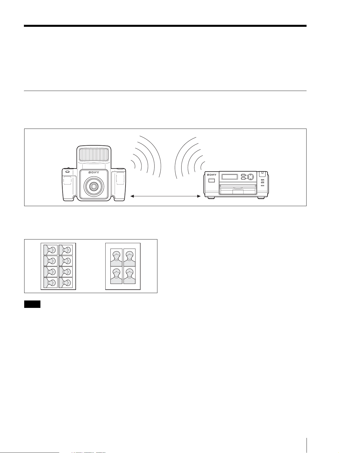
The Sony UPX-C300 digital printing system is designed
to allow you to take passport photos and similar ID
pictures with a digital camera, and then print them at
high image quality and resolution (403 dpi) in full color
or black & white.
Two types of print paper are supported: UPC-X46 series,
and UPC-X34 series.
The system adopts Bluetooth wireless technology,
which enables communication between the camera and
printer without using cables.
System Configuration
You can send images from the camera to the printer without a cable.
For details on the Bluetooth function, see “Setting the Bluetooth Functions” on page 51.
Bluetooth transmission
Camera
Printer
MENU
EXEC
less than 10 m
without obstruction
You can print pictures with the best face size according to the purpose of the pictures. The face size can be determined
automatically or you can finely adjust it manually while looking at the frame.
The pictures taken can be printed in a variety of layouts for passport photos and similar ID pictures or the size of the
print pack in use.
PRINT
ALARM
Note
Camera image data cannot be sent to any other peripheral device but the printer.
System Overview
5
Page 6
Operation Flow
STD
P
037
0.00
EV
STD
P
037
1/250 F4.7
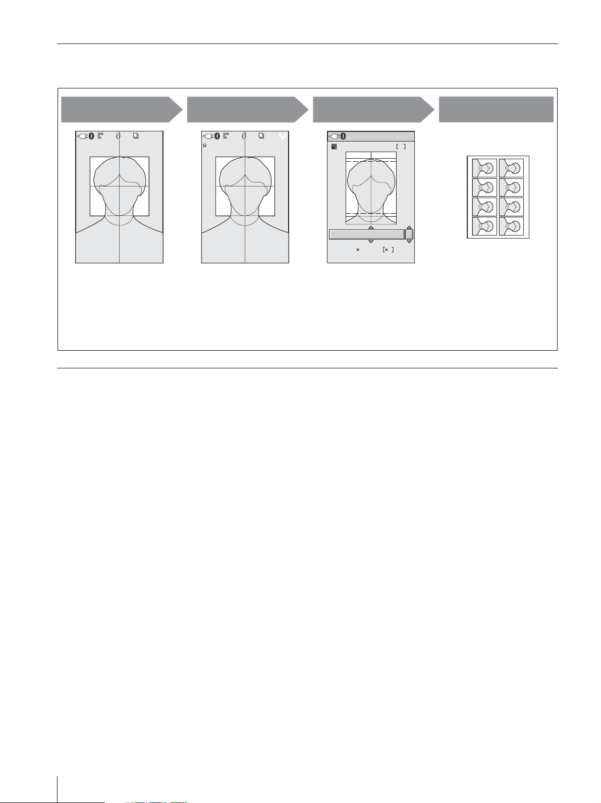
This system allows you to shoot and print ID pictures in which facial sizes can be adjusted to fit specific frame standards.
Shoot
037
STD
STD
Shoot pictures while viewing
the LCD to make sure the
subject’s face fits within the
frame. Use the lines in the
frame to center the face, and
fit the top of the head and
chin perfectly within the
frame.
037
P
Useful Features
Auto-Review/
Playback
037
STD
STD
0.00
0.00
EV
EV
1/250 F4.7
1/250 F4.7
Review the photo and adjust
the size of the face as
necessary. Press the AUTO
FRAME button to adjust the
face size automatically.
037
P
Print Preview Print
Bluetooth
1. Sony UP-DX100
EU : Passport
45 35mm 8
Specify the ID photo frame
type and the number of
prints. If, for example, the
area of the eyes is
predetermined for a
particular ID picture, you can
readjust the face size as
necessary.
1
3
The picture displayed during
print preview is automatically
laid out and printed.
Additional frames
If an ID photo frame you desire is not provided or you simply wish to modify one of the ID photo frames provided, you
can register up to five additional frame types.
Die-cut print
You can enable the die-cut print function to print an extra 3 mm around all sides of a picture, creating ideal prints for
die cuts.
Print queue
By enabling the print queue function, you can select multiple pictures and print them one after the other.
Color and black & white adjustments
This system allows you to adjust color and black & white print settings from the camera. You can quickly confirm
adjustment results using the guide print function.
6
System Overview
Page 7

Flash Modes and Example Shooting Conditions
The camera offers three flash modes.
When setting up, make sure the distance between the
camera and the subject (L) is set so that apparent face
size fits the selected frame (guidelines) at about
1.8 meter. Minor adjustments to apparent face size can
be made with the zoom.
Auto Flash ( )
The built-in flash fires at optimum brightness for a
subject about 1.8 meter away.
Use the v and V control buttons to set a negative EV
value when the distance L is less than 1.8 meter, or a
positive EV value when the distance is more than
1 meter. Be sure to take a test picture to check the
results. This mode is suitable for indoor ID portraits in
which the built-in flash is the main light source and a
shadow-clearing flash is connected to the camera by
synchronization cord.
Forced flash + manual exposure mode
()
You can manually set aperture and, shutter speed, and
select one of seven flash intensity levels (2 0.5EV) for
the built-in flash before shooting. This mode is suitable
for shooting portraits in which the built-in flash acts as a
trigger for the main light source, an external flash
connected to the camera by synchronization cord.
Large-size synchronized flash
L
Synchronized
flash
No flash + manual exposure mode ( )
In this flash mode, the aperture and shutter speed are set
manually, and the built-in flash does not fire.
The built-in flash does not fire. This mode is suitable for
shooting indoors under stable light sources, such as
L
studio light, video light, and fluorescent light.
Studio light (halogen light, etc.)
L
System Overview
7
Page 8
Flash Mode Setting Parameters
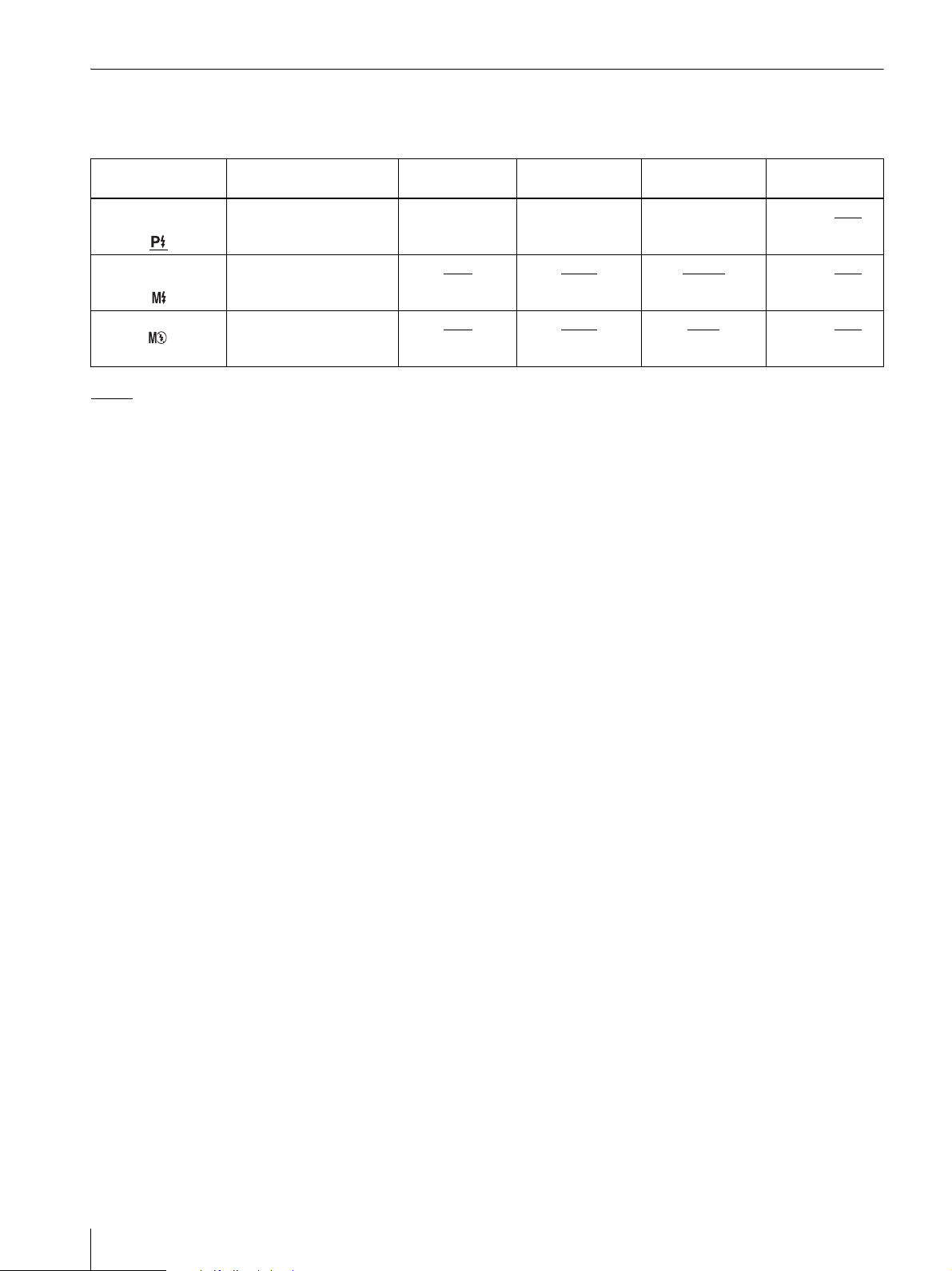
The flash mode is factory set to Program, but you can change the setting using the menus if necessary. The shooting
conditions available for configuration differ depending on the flash mode setting, as shown in the table below.
Flash Mode Flash Control Aperture Shutter Speed White Balance Exposure
Compensation
Controlled Flash
without pre-flash
Forced Flash
without pre-flash
Exhibit Flash No Lighting F4.7
Program with Zoom and EV Fixed
7 steps
(100/70/50/35/25/18/12%)
without Preflash
(Open)
F4.7
(F4.7 or F5.6)
(F4.7 or F5.6)
: Default setting
Effects of the F value while shooting
Even if the F value is changed through zoom operations, the flash intensity level and ISO sensitivity are automatically
adjusted before shooting to ensure that the brightness of a captured image will not be affected.
Fixed
(1/250)
1/250
(1/2 to 1/1000 [s])
1/250
(1/2 to 1/1000 [s])
Program –2.0EV to 0EV to
5500K
(Program, 3000 to
7000K or OnePush)
Auto
(Program, 3000 to
7000K, OnePush)
+2.0EV (in 1/4EV
–1.0EV to 0EV to
+2.0EV (in 1/4EV
–1.0EV to 0EV
+2.0EV (in 1/4EV
steps)
steps)
to
steps)
8
System Overview
Page 9
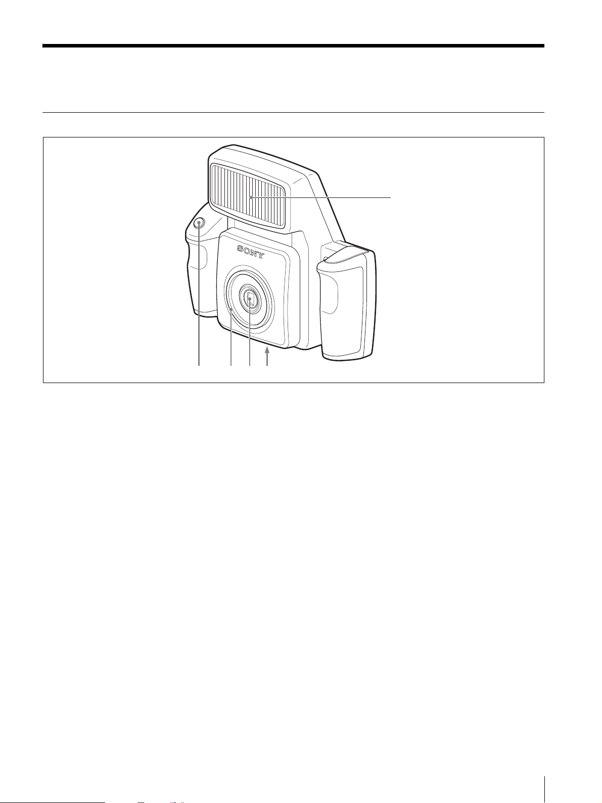
Names and Functions of Parts
For details, see the pages in parentheses.
Camera
1
2345
Front
A Flash (7, 8)
Fires according to the FLASH MODE setting.
B Tripod screw hole (16)
Used to attach the camera to the tripod.
C Lens (f=12.5 to 25.0 mm (1/2 to 1"), F-4.7 (W) to
F-5.5 (T))
Autofocus lens with 2x optical zoom.
D Lens filter thread
Used to attach a commercially available lens filter (ø 52
mm).
E Release button (21)
Press this button to capture the image shown on the LCD
and record it to the camera’s built-in memory.
Pressing the button halfway activates the autofocus
function, and pressing it all the way releases the shutter.
The captured image is compressed and saved in JPEG
format.
Names and Functions of Parts
9
Page 10
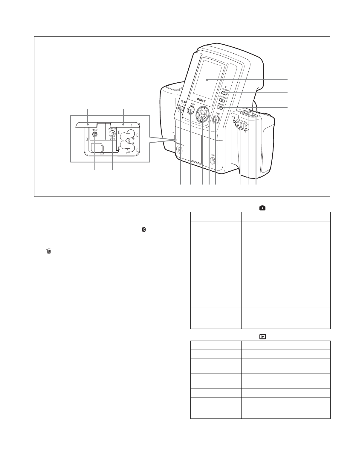
Rear
567890q
q
1
2
3
qdqf
4
qgqh
a
s
A LCD screen
Use it to display images captured by the lens, play back
images, or display menu.
When the Bluetooth function is active, the icon is
displayed.
B /COLOR/B&W (Delete/Color/Black & white)
button (23, 25)
Delete
During Auto Review mode or image playback, pressing
this button deletes the image displayed on the LCD.
Color/Black & white
While the print preview screen is displayed, pressing
this button selects whether to print in color or black &
white.
C AUTO FRAME (automatic position matching)
button (22, 23)
While the ADJUST screen is displayed, pressing this
button automatically determines a face size to fit the
frame.
D PRINTER button (58)
Selects a printer when multiple printers are used.
E Standby lamp
Indicates the camera’s status.
When the mode switch is
Lamp status Camera status
Lights (orange) Normal operation
Flashing (orange) The camera is starting up or Bluetooth
authentication is in progress. Or, AUTO
ERASE is off and the internal memory
is full so that no more images can be
stored.
Flashing rapidly
(orange)
Flashing (red) This indicates there is little battery
Flashing rapidly (red) The camera is shutting down.
Lights (red) This indicates camera malfunction.
The camera is preparing to take the next
picture, the flash is being charged, or
data is being stored.
power left if batteries are used.
Contact your nearest Sony dealer or
Sony Service Center.
When the mode switch is
Lamp status Camera status
Lights (green) Normal operation
Flashing (green) The camera is starting up or Bluetooth
Flashing (red) This indicates there is little battery
Flashing rapidly (red) The camera is shutting down.
Lights (red) This indicates camera malfunction.
authentication is in progress.
power left if batteries are used.
Contact your nearest Sony dealer or
Sony Service Center.
10
Names and Functions of Parts
F On/standby switch (19, 20)
Turns camera power on or sets it to standby.
Page 11

G Zoom lever (21, 22, 23)
When the mode switch is set to
Adjusts the angle of view. In most forms of ID, the size
of the face in the photo is regulated. By using the zoom
function, you can adjust the size of the face while
maintaining a fixed camera position. Up to 2× zoom is
available.
T: Telephoto zoom.
W: Wide-angle zoom.
When the mode switch is set to
During playback, switches between nine-picture
multiple display and single-picture display.
T: Nine-picture multiple display is switched to single-
picture display.
W: The display is toggled between a single-picture
display and a nine-picture multiple display.
When displaying the ADJUST screen
Zooms in or out of the displayed image.
T ( ): Zoom in on an image.
W ( ): Zoom out of a zoomed in image.
Note
If you use the MENU button to exit a menu or return to
auto-review display from the ADJUST screen, any
adjustments you have made will not be applied.
L Mode switch (19, 24)
You can switch between the following two modes.
: Shooting mode
: Playback mode
M Battery compartment lid (15)
Insert four commercially available Sony AA NiMH
(nickel-metal hydride) rechargeable batteries (type NHAA, max. 2700 mAh).
N External connector cover (14, 15)
Open it when connecting to the AC power adaptor or
external flash.
O DC IN (14)
Connects to the supplied AC power adaptor.
H PRINT button (23)
When the mode switch is set to or during autoreview display, press this button to print the image
displayed on the LCD. Press the button once to make the
adjust screen appear, and press the button again to send
the image data to the printer for printing.
I b v V B control buttons
When the mode switch is set to
Use v or V to change the exposure compensation value
(EV value).
When the mode switch is set to
Use b or B to select a playback image to display on the
LCD.
When the ADJUST screen is displayed
Use these buttons to move the displayed image up,
down, left, or right.
When navigating menus
Use these buttons to select and set menu items.
J ENTER button
Press this button to confirm a selection or operation.
During auto-review display or image playback, pressing
this button displays the ADJUST screen.
While the ADJUST screen is displayed, pressing this
button applies the image size adjustments and returns to
the previous screen display.
P FLASH jack
Connect a cord from an external flash that supports an X
contact.
When an external flash that supports an X contact is
connected with the synchronization cord, the flash lights
synchronizing with the shutter.
K MENU button (26, 28)
Press this button to display menus. You can also press
this button to exit menus or return to auto-review display
from the ADJUST screen.
Names and Functions of Parts
11
Page 12

Printer
Front
D
I
G
I
T
A
L
P
H
O
T
O
P
R
I
N
T
E
R
1
M
E
N
U
E
X
E
C
PRINT
ALARM
2
34 0956 8
7
N
E
P
O
H
S
U
P
PRINT
ALARM
Bluetooth antenna (inside)
A 1 (On/Standby) button/lamp (19)
When you press this button, the lamp lights and power is
supplied to the printer. When you press the button again,
the lamp turns off and the printer enters standby status.
B Paper tray slot (17)
Insert the paper tray here.
C Operation display
When the printer is on, information such as operation
status and menu items display here.
D MENU button (31)
Press this button to display menus or cancel changes
made in menus.
E EXEC (Execute) button (24, 50)
Press this button to execute menu items selected while
navigating menus and after exchanging the ribbon
cartridge.
F Control button (24, 50)
When navigating menus, use this to select and set menu
items.
ALARM lamp: Lights when an error such as a paper
jam occurs.
H Print cartridge cover (18)
When inserting or removing print cartridges, press the
area where PUSH OPEN is written to open the cover.
I Print cartridge slot (18)
Insert the print cartridge here.
J Cartridge release lever (18)
Raise this when removing a print cartridge.
Note
This lever is disabled while printing is in progress.
G Lamps
lamp: Lights when the Bluetooth function
is enabled.
PRINT lamp: Lights when printing is in progress, and
flashes when the printer is receiving image data.
lamp: Lights when the paper or print cartridge
runs out or the paper and print cartridge differ in
size.
12
Names and Functions of Parts
Page 13
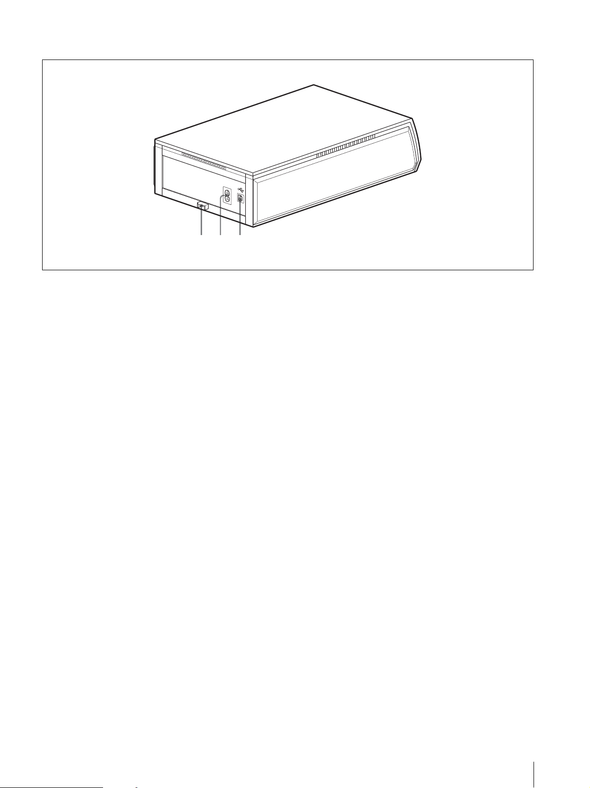
Rear
- AC IN
123
A Paper jam cover (64)
When a paper jam occurs, remove this cover and remove
the jammed paper.
B -AC IN connector (19)
Connect to a power outlet using the power cord.
C USB connector
Not used on this system
Names and Functions of Parts
13
Page 14
Supplied Accessories
Preparations
Confirming the Contents
Make sure that the following accessories are supplied
with your system.
Paper tray for the UPC-X46 series (1)
Paper tray for the UPC-X34 series (1)
Tray cover (1)
UPA-AC05 AC power adaptor (1)
Cleaning cassette (1)
Warranty card (1)
Operating Instructions (1)
Quick Reference Guide (1)
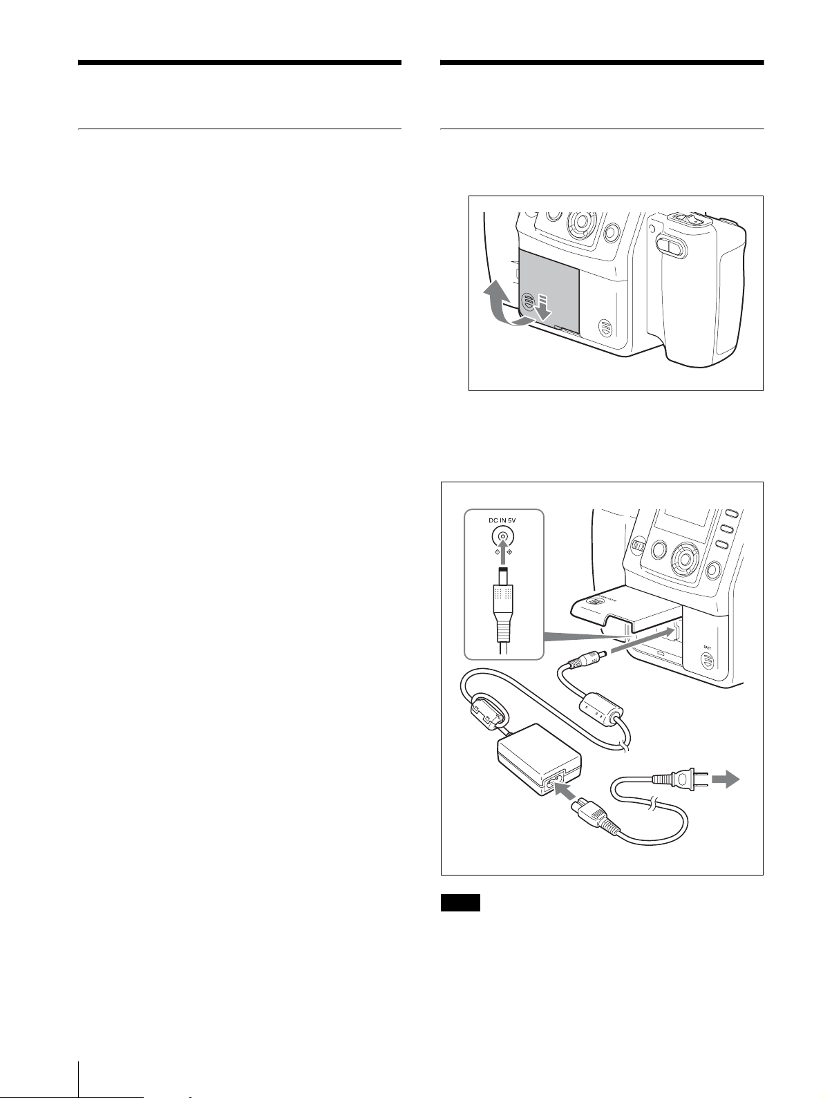
Preparing the Camera
1
Slide to open the external connector cover.
2
Connect the supplied UPA-AC05 AC power
adaptor to the DC IN jack on the camera, and
connect the AC adaptor to a power outlet with the
power cord.
Camera
14
Supplied Accessories
to power outlet
UPA-AC05 AC power
adaptor (supplied)
AC power cord
Note
Make sure that the AC power adaptor is near the power
outlet during use. If the camera malfunctions,
immediately disconnect the AC power adaptor from the
power outlet to cut off power supply.
Page 15
3
Close the external connector cover and press down
while sliding it to make sure it locks into place.
3
Close the cover and press down while sliding it to
make sure it locks into place.
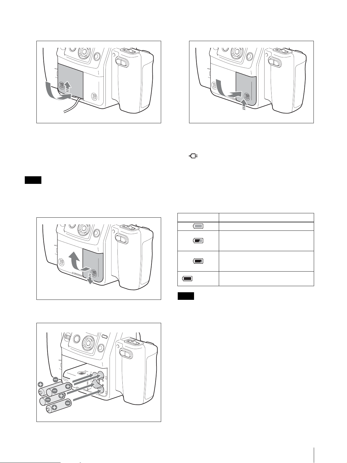
When using batteries
For the camera in this system, you can use four size AA
Nickel Metal Hydride batteries available commercially.
Use the following steps to insert the batteries into the
camera.
Note
Use only Sony NH-AA (max. 2700 mAh) batteries.
1
Slide the battery compartment cover at the rear of
the camera to open it.
Power Status Indicators
When using an AC power supply
The icon appears at the bottom right of the camera’s
LCD.
When using batteries
When the battery charge is getting low, the following
icons appear at the bottom right of the camera’s LCD.
Use these to get a general idea of when to replace the
batteries.
Indicator Power status
The batteries are sufficiently charged.
The battery charge is getting low, but you
can continue shooting. Ready the AC
power adapter or a new set of batteries.
The battery charge is low, and shooting
will be disabled shortly. Use the AC power
adapter or replace the batteries.
(flashing)
Note
The batteries are fully discharged.
Shooting is disabled.
2
Insert the four size AA batteries.
Connecting the AC adapter while the batteries are inside
the camera will not recharge the batteries. To recharge
the batteries, use the specifically designed battery
charger.
Preparations
15
Page 16
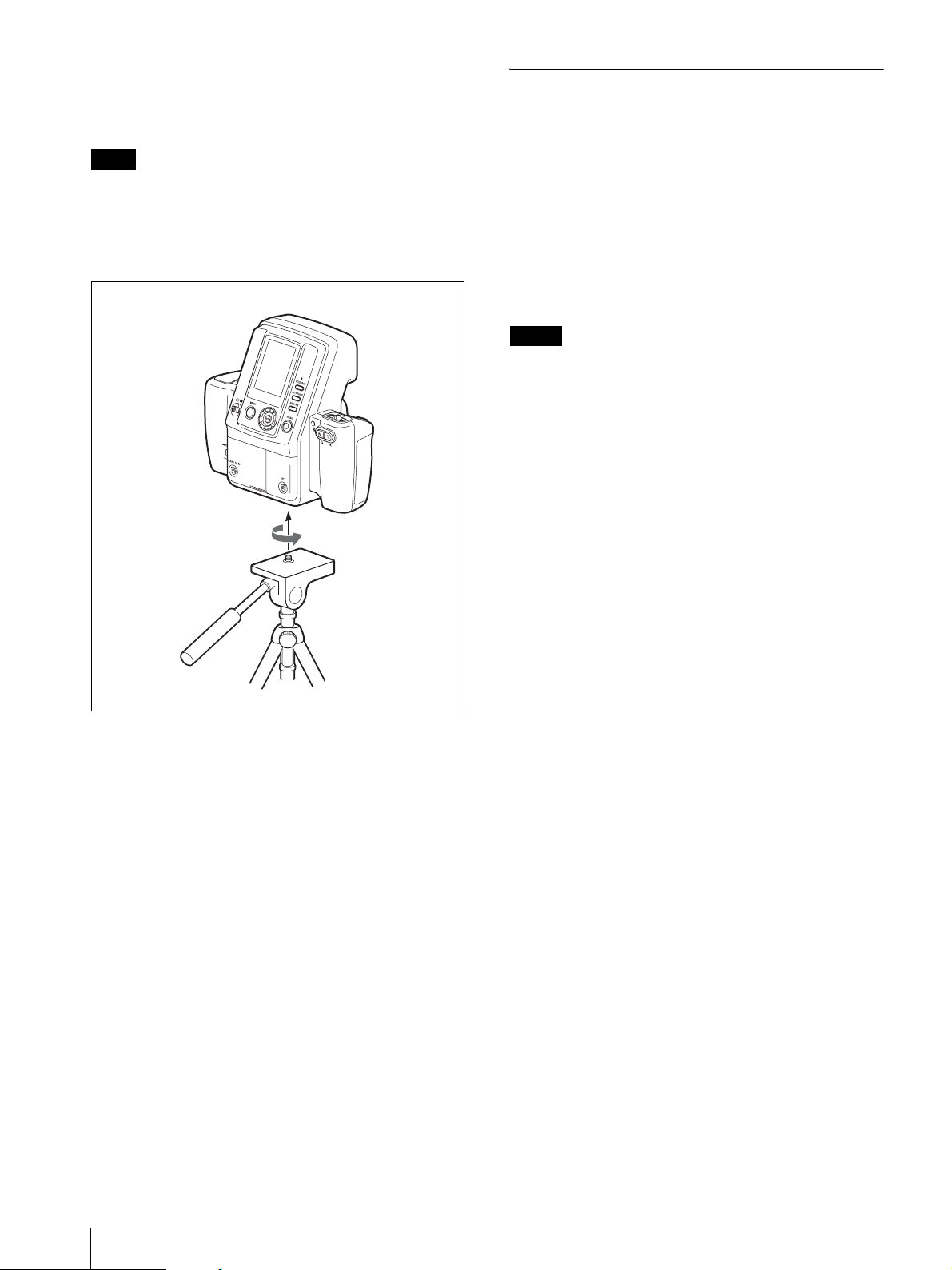
To attach the tripod
You can attach the camera to a tripod using the tripod
screw hole located on the underside of the camera.
Note
Tighten the screw for the tripod securely. If the screw is
loose, the camera may fall off. However, using too much
force when tightening may damage the screw hole.
Make sure that the screw is inserted straight before
tightening it.
Camera
Tripod
Preparing the Printer
Before using the printer for the first time, perform the
following steps to insert the print cartridge and paper
tray. These preparations are not required at every use.
Perform them only when necessary.
Print packs
In order to print, a print pack designed for this printer
(UPC-X46 series, or UPC-X34 series) (not supplied) is
required. A print pack is a set consisting of print paper
and a print cartridge.
Notes
• Do not rewind the ink ribbon and use the rewound
print cartridge for printing. Doing so may produce
incorrect printing results or damage the printer.
• Only use print packs designed for this printer.
• Always use sets of print cartridges and print paper that
match in size. Using a print cartridge together with
print paper of a different size may produce incorrect
printing results or cause paper jams and other
problems.
• Do not print on used print paper. Printing an image
twice on the same paper will not make the image
darker and may damage the printer.
• Avoid touching the printing surface of the print paper
and the ink ribbon of the print cartridge, and avoid
storing print packs in locations subject to high
temperatures and humidity, excessive dust, or direct
sunlight. Fingerprints or dust on the printing surface or
ink ribbon may lower the print quality.
• When removing partially used print cartridges and
print paper from the printer for storage, store them in
their original packaging.
16
Preparations
Page 17

To load the print paper
Note
1
Load the print paper into the paper tray.
Print paper
Riffle through the print paper before loading it with
the printing surface (the side without imprinting)
facing up. Make sure that the arrow on the
protective sheet is pointing in the same direction as
the arrow on the tray. You can load up to 25 sheets
when using the UPC-X46 series and 30 sheets when
using the UPC-X34 series.
2
Remove the protective sheet on the print paper.
Note
Be sure to keep the protective sheet as it is used
when cleaning the inside of the printer.
3
Insert the paper tray into the printer until it clicks
into place.
M
E
N
U
E
X
E
D
IG
IT
A
L
P
H
O
T
O
P
R
IN
T
E
R
C
P
R
IN
T
A
L
A
R
M
Do not touch the printing surface. Fingerprints or
dust on the printing surface may lower the print
quality.
Notes on loading the print paper
• Load UPC-X46 series print paper into the large paper
tray and UPC-X34 series print paper into the small
paper tray. Mismatch between the paper and tray sizes
may result in a paper jam.
• Do not remove or insert the paper tray while printing
is in progress.
• If the print paper does not feed automatically, the
lamp lights and a message displays. Pull out the
paper tray, and check for a paper jam.
• When loading additional print paper into the tray,
make sure that the total number of sheets does not
exceed 25 for the UPC-X46 or 30 for the UPC-X34
series. Do not load different types of paper in the tray
together. Doing so may result in a paper jam.
• Do not write or print text on the print paper before
printing. The printer may not be able to print on paper
that has been written on. When writing on an image
after printing, use an oil-based ink pen. Text from
word processors cannot be printed on the print surface.
• Do not attach stickers or tape on the print paper before
printing.
• Do not print on used print paper. Printing an image
twice on the same paper will not make the image
darker and may damage the printer.
• Do not fold or bend the print paper before printing.
Doing so may damage the printer.
• When paper is ejected after printing, do not allow
more than five sheets to accumulate in the paper tray.
Doing so may result in a paper jam.
Notes on storage
• Avoid storage in locations subject to high
temperatures and humidity, excessive dust, or direct
sunlight.
• Do not store print paper sheets with their printing
surfaces touching each other. Also, do not allow
printing surfaces to remain in contact with plastic or
rubber materials containing vinyl chloride or
plasticizers for extended periods of time. Doing so
may result in discoloration or bleaching.
• When removing unused print paper from the printer
for storage, store it in its original packaging.
PUSH OPEN
Preparations
17
Page 18

To attach the tray cover
Keep the supplied tray cover on the paper tray when not
in use to protect the print paper inside from dust and
other particles. You can attach a tray cover to any of the
UPC-X46, and UPC-X34 series’ paper trays.
Tray cover
To load the print cartridge
1
Press the upper portion of the print cartridge cover
where PUSH OPEN is written to open it.
To replace the print cartridge
When the print cartridge runs out, the lamp lights
and an error message appears on the operation display.
Perform the following steps to replace the print
cartridge.
1
Press the upper portion of the print cartridge cover
where PUSH OPEN is written to open it.
2
Raise the cartridge release lever.
M
E
N
U
E
X
E
D
I
G
I
T
A
L
P
H
O
T
O
P
R
I
N
T
E
R
The cartridge is released, allowing you to pull it out.
C
P
R
I
N
T
A
L
A
R
M
Cartridge release lever
M
E
N
U
E
X
E
D
I
G
I
T
A
L
P
H
O
T
O
P
R
I
N
T
E
R
C
P
R
I
N
T
A
L
A
R
M
Print cartridge cover
2
Insert the print cartridge into the cartridge slot, and
push until it clicks into place.
M
E
N
U
E
X
E
D
I
G
I
T
A
L
P
H
O
T
O
P
R
I
N
T
E
R
C
P
R
I
N
T
A
L
A
R
M
Print cartridge
3
Insert a new print cartridge, and close the cover.
4
Press the EXEC button.
Notes
• Never put your hand into the cartridge slot as the
inside can reach high temperatures.
• Do not rewind the ink ribbon and use the rewound
print cartridge for printing. Doing so may produce
incorrect printing results or damage the printer.
• If the print cartridge does not insert properly, remove
it once before reinserting it. If the ink ribbon is too
slack to be loaded, remove the slack by winding the
ink ribbon in the direction of the arrow while pressing
the spool. This is the only time the ink ribbon should
be wound.
18
3
Close the print cartridge cover.
4
Press the EXEC button.
Preparations
• When you turn on the printer with no print cartridge
loaded, the lamp lights.
Page 19
• Do not touch the ink ribbon or place the print cartridge
in a dusty location. Fingerprints or dust on the ink
ribbon may lower the print quality.
• Do not remove or insert print cartridges while printing
is in progress.
Notes on storage
• Avoid storage in locations subject to high
temperatures and humidity, excessive dust, or direct
sunlight.
• When removing a partially used print cartridge for
storage, store it in its original packaging.
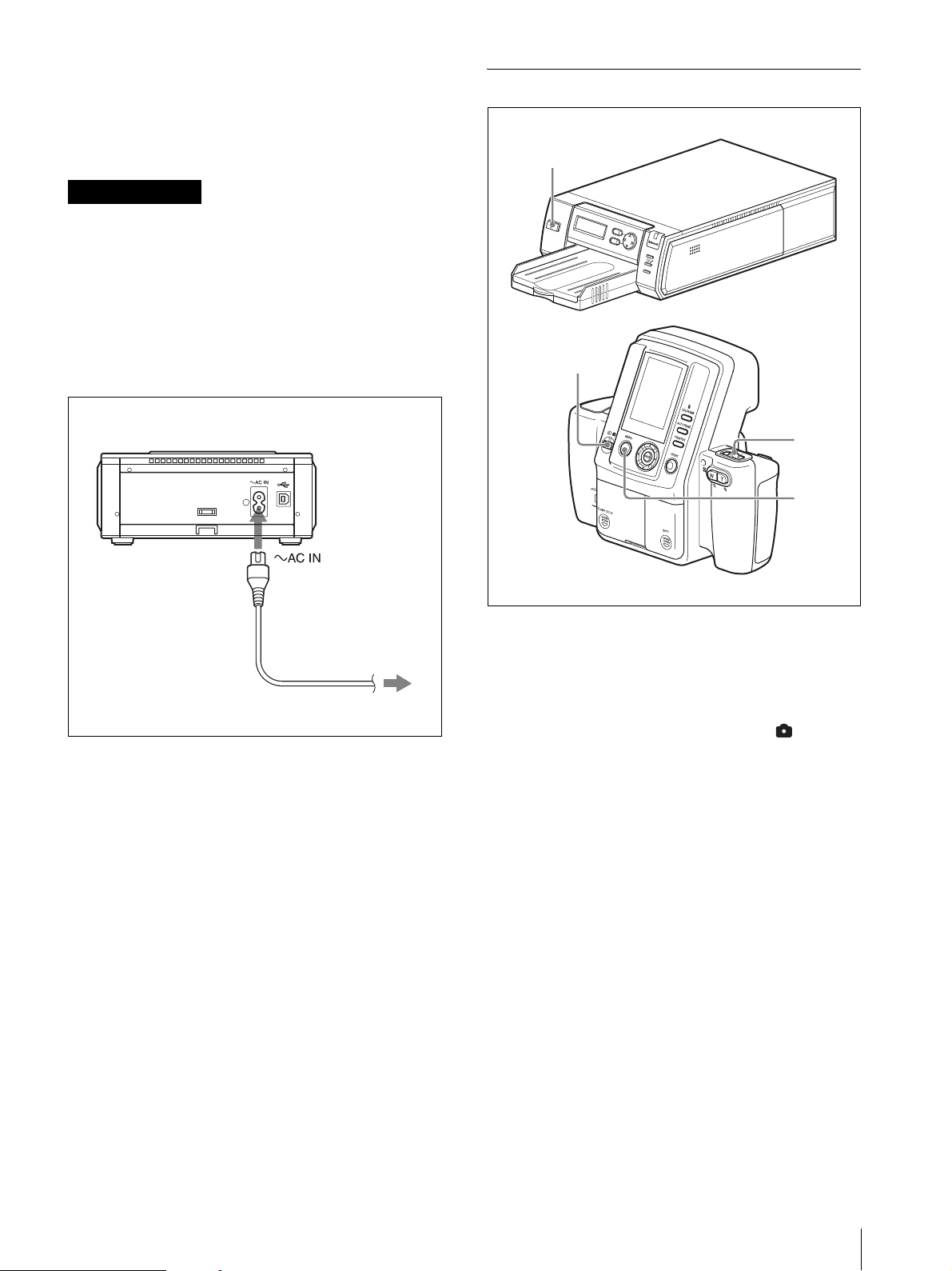
To connect the printer to a power outlet
Connect the printer to a power outlet using the power
cord.
Turning On the Power
1
M
E
N
U
E
X
E
D
I
G
I
T
A
L
P
H
O
T
O
P
R
I
N
T
E
R
C
P
R
I
N
SH OPEN
T
PU
A
L
A
R
M
2
Printer
Power cord
to power outlet
1
Turn on the printer.
Check that Ready BT RSSI [- - - -] appears on the
operation display.
2
Set the mode switch on the camera to .
3
Set the on/standby switch on the camera to ? (on).
When turning on the camera for the first time, the
default setting screen appears.
For details on default settings, see “The first time
you turn on the camera (default setting)” on page
20.
3
4
The camera starts searching for the printer, and
“DISCOVERING” appears on the LCD. When the
camera finds the printer, “DISCOVERED” appears,
and the printer name and Bluetooth address are
displayed in black on the LCD. If the color of the
printer name and Bluetooth address do not change
to black but remain in gray, set the printer and
camera to standby mode and perform steps 1
through 3 again.
Preparations
19
Page 20

4
Press any button on the camera.
The Bluetooth display is turned off, and you can
start taking a picture.
If the printer name and Bluetooth address are still
displayed in gray, and “DISCOVERED” does not
appear, or “NO PRINTER” appears, see “Adding/
Registering a Printer” on page 56, and take appropriate
action. If the problem still persists, contact your Sony
dealer or your Sony service facility.
The first time you turn on the camera
(default setting)
When you turn on the camera the first time, the default
setting screen appears before your camera connects to
the printer via Bluetooth. Use the following steps to
select a language and a region.
1
Press the v or V control button to select a language
and then press then ENTER button.
The REGION screen appears.
2
Press the v or V control button to select a region,
and then press the ENTER button.
A screen appears for you to confirm the selected
language and region.
3
Press the v or V control button to select OK, and
then press the ENTER button.
To set the printer and camera to standby
mode
When you finish your operation, set the printer and
camera to standby mode.
Operations (Shooting and Printing)
Image resolution settings
If you want to place priority on picture quality, we
recommend setting RESOLUTION to HIGH in
advance.
For details on how to select an image resolution, see
“Setting the Image Resolution” on page 32.
Shooting condition settings
The shooting condition settings on the camera are
factory set to allow shooting without manual
configuration, but you can change the shooting
conditions as necessary using Shooting menu.
We recommend configuring the settings to match your
usage environment.
For details on setting the shooting conditions, see
“Flash Mode Setting Parameters” on page 8.
Note
Images may be damaged and the camera may not
operate properly if power is cut off while shooting or
deleting pictures. Make sure that the AC power adaptor
does not disconnect and the battery compartment cover
does not open during operation.
1
Press the on/standby button to set the printer to
standby mode. The lamp goes out, and the printer is
set to standby mode.
2
Set the on/standby switch on the camera to 1
(standby).
The camera stores the latest setting data in memory and
enters standby mode. While the camera is storing data,
the clock appears on the LCD, and the standby lamp is
lit. During transfer of data for storage, do not disconnect
the AC power adaptor or remove the batteries.
Note
If you cut off the power supply by disconnecting the AC
power adaptor or removing the batteries while the
camera transfers settings data to memory, any new
settings may be lost, and the camera may revert to its
previous settings.
20
Operations (Shooting and Printing)
Page 21
Taking a Picture
0.00
EV
STD
P
W T
037
1/250 F4.7
1
2, 3
To delete the last picture taken
Perform the following steps to delete the last picture
taken while it appears in the auto-review display.
1
Press the button.
A screen asking you to confirm deletion appears.
2
Select OK by pressing the v control button, and
then press the ENTER button.
The picture displayed on the LCD is deleted, and
the camera returns to Shooting mode.
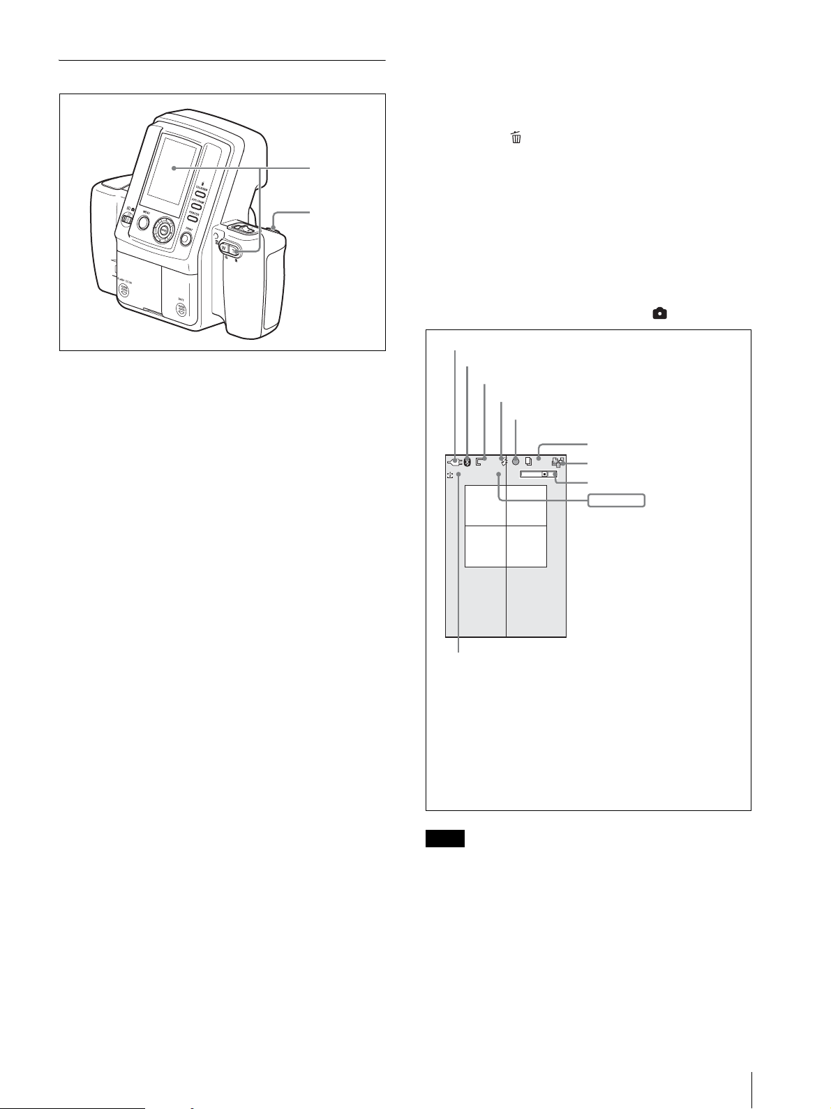
The LCD in Shooting mode
The following is an example of how the LCD may
appear when the mode switch is set to .
1
Point the camera at the subject, and adjust the frame
while monitoring the camera LCD.
Pressing the zoom lever allows you to adjust the
frame by zooming.
T: Telephoto zoom.
W: Wide-angle zoom.
When composing the picture, make sure the
subject’s face fits within the frame on the LCD.
Enlarge the face as much as possible while keeping
the entire face within the frame.
2
Press the release button halfway to focus.
Once the subject is in focus, a green focus mark
appears on the LCD.
If the focus mark turns red when you press the
release button halfway, the picture is not in focus.
Slowly press the release button halfway again.
3
Press the release button halfway until the focus
mark turns green, then press the button the rest of
the way.
A picture is taken, and it appears immediately on
the LCD. This feature is known as the auto-review
display. The picture is also simultaneously stored in
the camera’s internal memory. During the transfer
of data to memory, the standby lamp rapidly flashes
orange. Once the data is stored and the built-in flash
is charged for the next picture, the standby lamp lits
orange.
Pictures can be printed directly from the auto-review
display without switching the mode switch setting.
For details, see “Printing the Last Picture Taken (From
the Auto-Review Display)” on page 22.
To take the next picture, press the release button or zoom
lever to turn off the auto-review display, and then repeat
steps 2 and 3.
Power source (AC power adaptor or battery indicator)
Bluetooth indicator
Resolution
Flash mode
Focus mark
STD
STD
0.00
0.00
Exposure compensation
1) Appears when the Bluetooth module is set to ON.
2) Appears when the release button is pressed halfway.
3) Appears when the print queue function is enabled.
4) Appears when the zoom lever is pressed.
5) Settings for shutter speed and aperture appear when the
6) Appears when the v or V control button is used to change
Note
P
EV
EV
release button is pressed.
the exposure compensation value, or when the release
button is pressed halfway.
WT
037
037
1)
2)
Remaining number of pictures
(Estimated number that can be
captured at the set resolution)
Print queue icon
Zoom bar
1/250 F4.7
1/250 F4.7
Shooting conditions
6)
4)
3)
5)
To make it easy to determine the frame of the subject,
this camera keeps the brightness of the LCD at a certain
level, regardless of the exposure, brightness of the
subject, or lighting conditions of the surrounding areas.
For this reason, the brightness of the LCD is different
from the actual brightness of the captured image.
Operations (Shooting and Printing)
21
Page 22
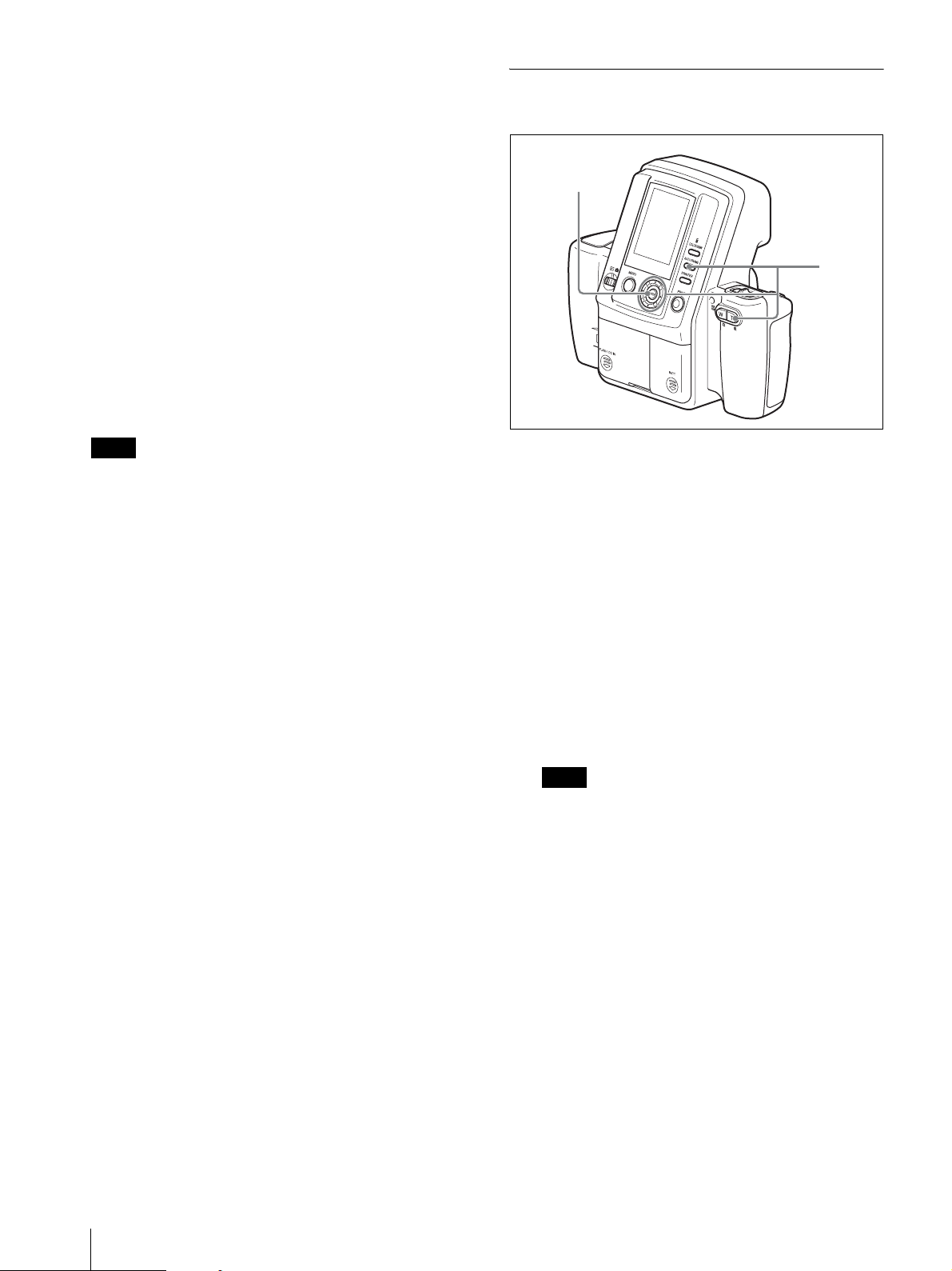
Autofocus function
Pressing the release button halfway activates the
autofocus function. Once the subject is in focus, a green
focus mark appears in the top of the LCD. When you
press the button the rest of the way, the shutter releases
and the picture is taken.
If the subject is out of focus when the button is pressed
halfway, a red focus mark appears on the LCD. Lift your
finger off the release button, and then slowly press the
button halfway again. Even if the red focus mark
appears, you can press the release button the rest of the
way to take the picture.
Pressing the release button fully instead of pausing
halfway will still take a picture, but the autofocus and
exposure compensation functions will not activate.
If SOUND of the SETUP menu is set to SHUTTER or
ON, a sound is heard when the release button is pressed
halfway and when pressed again the rest of the way.
Printing the Last Picture Taken (From the Auto-Review Display)
1, 3
2
Note
If slowly pressing the release button halfway does not
refocus the image, set the camera to standby mode and
then turn it on again.
In addition, the autofocus function may not work
properly in the following situations:
• The subject lacks enough contrast.
• The subject includes an extremely bright object.
• The background is abnormally dark.
• The subject is positioned within 80 cm of the camera.
Exposure compensation function
Exposure compensation can easily be obtained by
pressing v or V of the control button. Each time you
press the button, the exposure compensation value
displayed on the LCD changes.
For details on the exposure compensation, see
“Compensating the Exposure” on page 35.
1
During auto-review display, press the ENTER
button.
The ADJUST screen appears, and a frame is
displayed in red on the LCD.
2
Adjust the size of the image.
1) Press the AUTO FRAME button.
The image is automatically adjusted so that the
face size of the subject fits the frame.
2) If necessary, use the following buttons to adjust
the size of the image.
– You can use the zoom lever to zoom in or out
of the image.
– You can press the v, V, b, or B control button
to move the display position of the image.
Note
If you press the AUTO FRAME button for an image
with a non-uniform background, the automatic
adjustment function may not work properly. In such
cases, press the zoom buttons or the v, V, b, or B
control button to manually adjust the size and
display position.
In addition, the automatic adjustment function may
not work properly if a face is too large or too small
for the frame on the LCD.
22
Operations (Shooting and Printing)
3
Press the ENTER button.
The LCD returns to the auto-review display.
The adjustments are applied, and the camera
returns to auto-review display.
If you press the MENU button, the camera returns
to auto-review display without applying the
adjustments.
Page 23
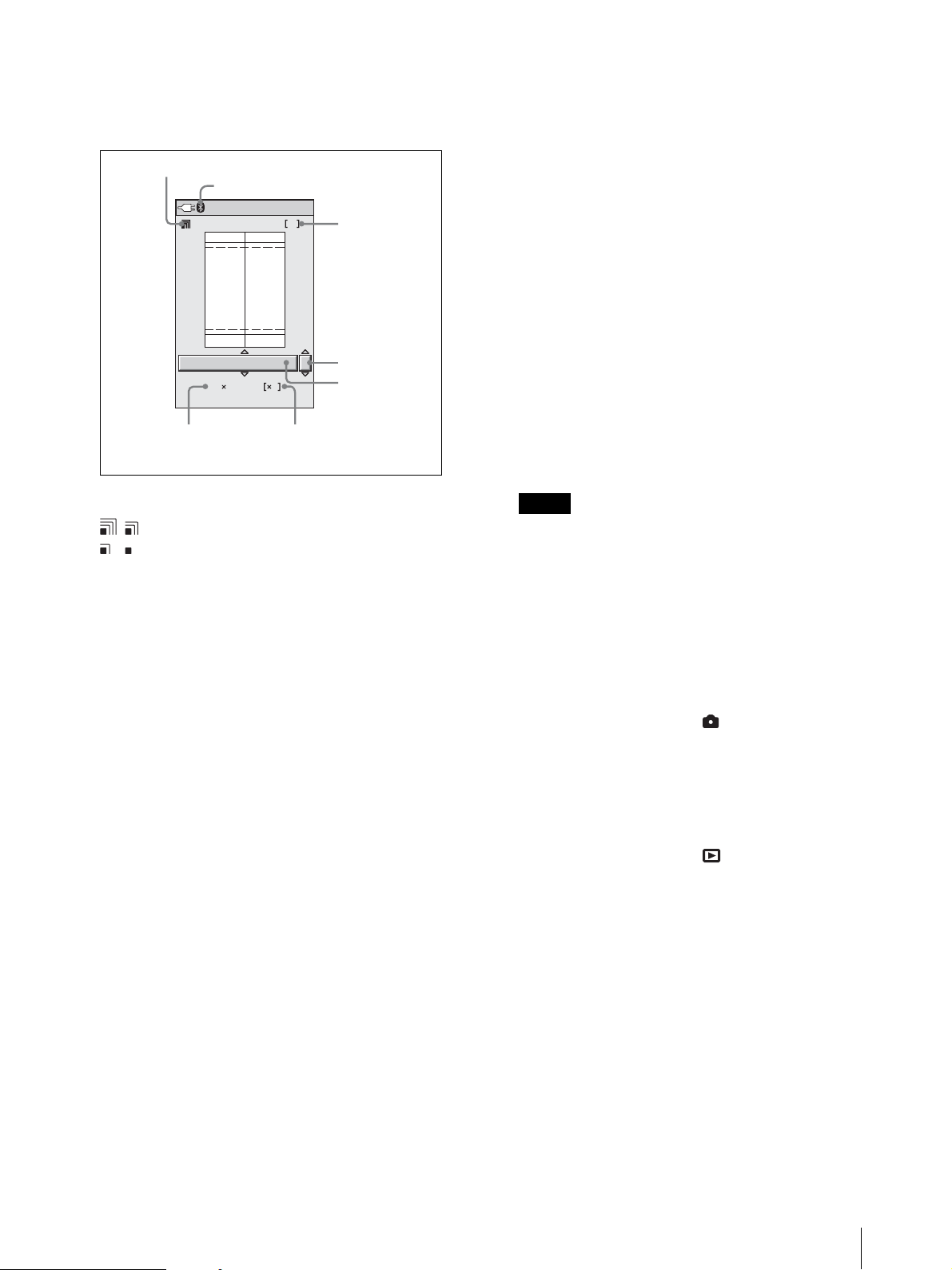
4
Press the PRINT button.
The print preview screen appears.
You can return to the auto-review screen (or
playback screen) by pressing the MENU button.
Reception indicator
Bluetooth indicator
Bluetooth
1. Sony UP-DX100
1)
1
Printer name
3) If necessary, use the following buttons to adjust
the size of the image.
– You can press the zoom lever to magnify or
reduce the image.
– You can press the control buttons (vVbB) to
move the displayed part of the image.
4) Press the ENTER button to return to the print
preview screen.
9
Press the PRINT button again.
Picture data are transmitted to the printer, and
“TRANSMITTING” and the progress bar appear
on the LCD.
EU : Passport 3
45 35mm 8
Number of framesFrame size
1) Appears when the Bluetooth module is set to ON.
Number of prints
ID Photo Frame
You can use the reception indicator on the top left
part of the screen to check the reception state.
: The reception is good.
: The reception is weak and therefore it may
take more time to send images.
Do not move the camera and printer until data
transmission is finished.
5
Press the v or V control button to select a ID photo
frame.
Press the v or V button repeatedly until the desired
ID photo frame appears.
For details, see “Setting up a Frame for Display
During Printing” on page 37.
6
Specify the number of copies to print.
1) Press the B control button once.
Now you can select the number of copies to
print.
2) Press the v or V control button to select the
number of copies to print.
7
Press the COLOR/B&W button to select whether to
print in color or black & white.
8
If necessary, adjust the size of the image to match
the selected ID photo frame.
1) Press the ENTER button.
The ADJUST screen appears.
2) Press the AUTO FRAME button.
The image is automatically adjusted so that the
face size of the subject fits the frame on the
screen.
While the CANCEL button is lit in orange, you can
cancel data transmission by pressing the ENTER
button.
When data transmission ends, the CANCEL button
changes to gray. The printer checks the print pack
then starts printing.
Notes
• Once the CANCEL button changes to gray, you
cannot cancel the print operation.
• Do not touch any button on the camera while the
CANCEL button is gray.
Once printing begins, “TRANSMISSION END. PUSH
MENU KEY TO CONTINUE.” appears on the LCD of
the camera. Press the MENU button to remove the
message.
When the mode switch is set to , the LCD returns to
the auto-review display. Once printing ends, you can
print the same picture again at a different size, color, etc.
You can also take another picture during printing. To
take the next picture, press the release button halfway or
press the zoom lever to turn off the auto-review display.
When the mode switch is set to , the LCD returns to
the playback image.
When a picture is printed, it is ejected onto the paper tray
on the printer.
An image number is printed at the bottom of the printed
image. This is the same number that appeared at the top
of the LCD during image playback.
Operations (Shooting and Printing)
23
Page 24
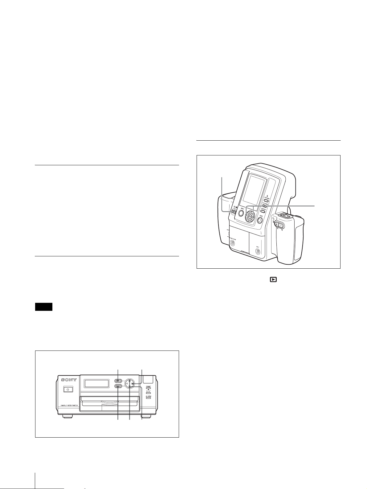
To adjust the print quality
On the camera, you can independently adjust the print
quality for color pictures and black & white pictures and
store the adjusted values. Once these values are stored,
the camera automatically selects the appropriate
adjusted value for color prints and black & white prints,
respectively.
For details on adjusting the print quality, see “Adjusting
the Picture Quality” on page 44.
To adjust black & white print quality
When you print a picture in black & white by selecting
B&W, the picture is printed by overlaying yellow,
magenta, and cyan, and therefore may not be perfectly
achromatic. To adjust the black tone, you can use the
print quality adjustment function on the printer.
2
Press V on the control button to display “COPY
PRINT [>>].”
3
Press B on the control button.
“COPY PRINT: 1 [1 – 9 PRINT: EXEC]” appears.
4
Set the number of sheets to be printed by press v or
V on the control button.
A value from 1 to 9 can be set.
5
Press the EXEC button.
The number of pictures set in step 4 is printed.
When printing completes, the READY screen
reappears.
Viewing a Picture on the LCD
Printing a Picture Stored in the Camera’s Built-In Memory
When a picture is taken, its data is stored in the camera’s
built-in memory. To print stored pictures, view them in
Playback mode and select the picture you wish to print.
Then perform the same steps as when printing a picture
from the auto-review display (on page 22).
For details on viewing pictures stored in memory, see
“Viewing a Picture on the LCD” on page 24.
Reprinting a Picture Stored in the Printer’s Memory (COPY PRINT)
The data for the last picture that was printed is stored in
the printer’s memory. You can reprint this picture.
Note
If you press the 1 button on the printer and set it to
standby mode (so the lamp goes out), the data stored in
the printer’s memory is deleted, and you cannot reprint
the picture.
1
1
Set the mode switch to .
A picture stored in the camera’s memory appears on
the LCD.
2
Select a picture to view by pressing the b or B
control button.
2
1
Press the MENU button.
24
Operations (Shooting and Printing)
13
54
2
Page 25
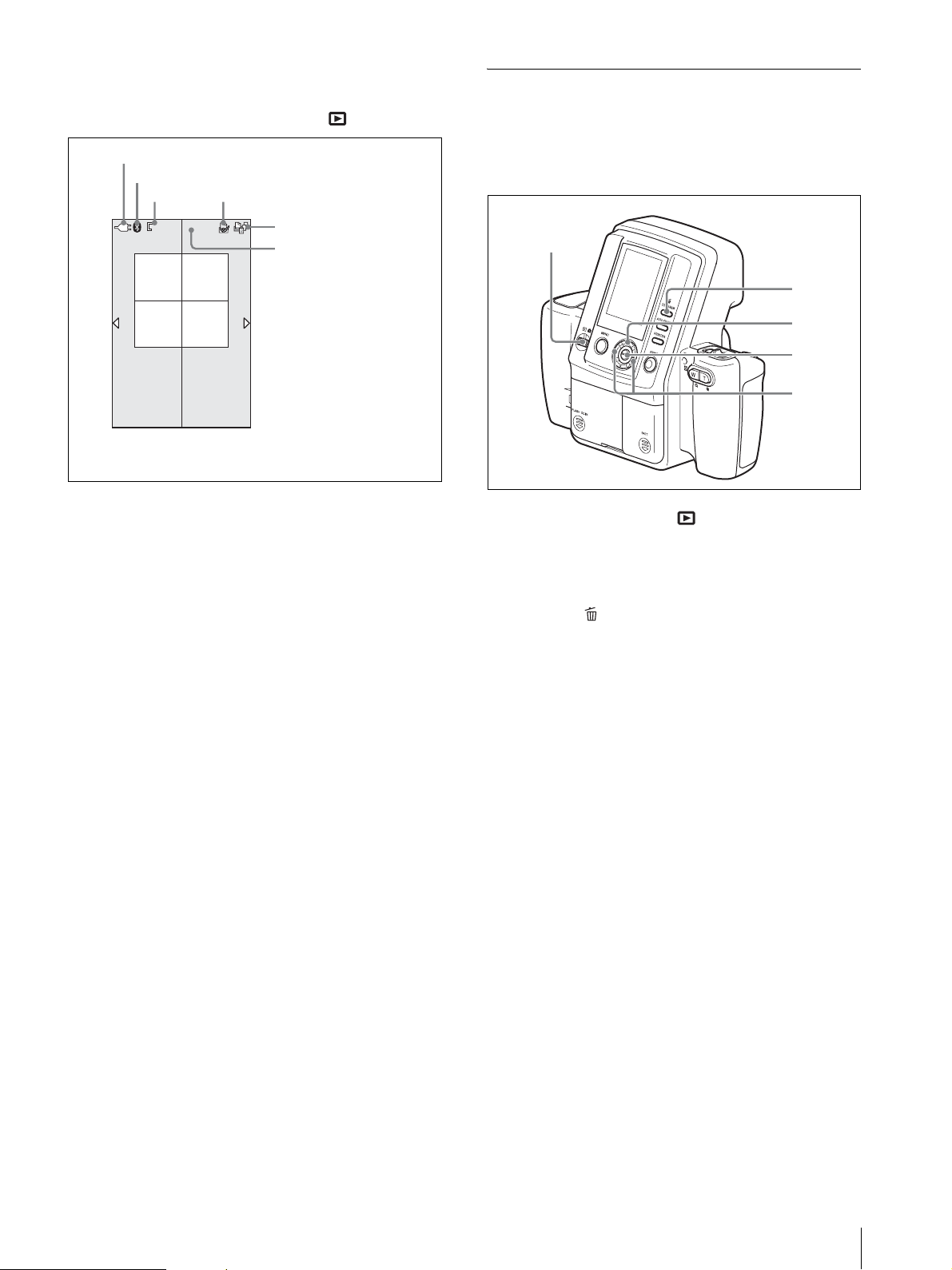
The LCD in Playback mode
STD
001/0/01818
The following is an example of how the LCD may
appear when the mode switch is set to .
Power source (Battery indicator or AC power adaptor)
Bluetooth indicator
Resolution Print queue flag
001
001/018
STD
STD
1) Appears when the Bluetooth module is set to ON.
2) Appears when the print queue function is enabled.
1)
2)
Print queue icon
Number of images currently
displayed/Total number of
images recorded
2)
Deleting a Picture
The procedure for deleting pictures is the same for both
single-picture display and nine-picture multiple display.
Deleting pictures in playback one by one
1
3
4
5
2
Displaying the nine-picture multiple
display
Nine pictures stored in the camera’s memory can be
displayed at a time on the LCD. Then you can quickly
search for a desired picture.
1
Press the W side of the zoom lever.
You can see nine pictures stored in camera’s
memory on the LCD.
2
Select a picture by pressing b, B, v or V of the
control button.
Pressing b or B selects the previous or next picture
respectively.
Pressing v or V displays the previous or next page
respectively.
3
Press the ENTER button or zoom lever.
The selected picture is displayed in full screen.
1
Set the mode switch to .
2
Select a picture to delete by pressing the b or B
control button.
3
Press the button.
The DELETE screen appears.
4
Select OK by pressing the V control button.
5
Press the ENTER button.
The selected picture is deleted from the memory.
To continue deleting pictures
Repeat steps 2 to 5 above.
Operations (Shooting and Printing)
25
Page 26
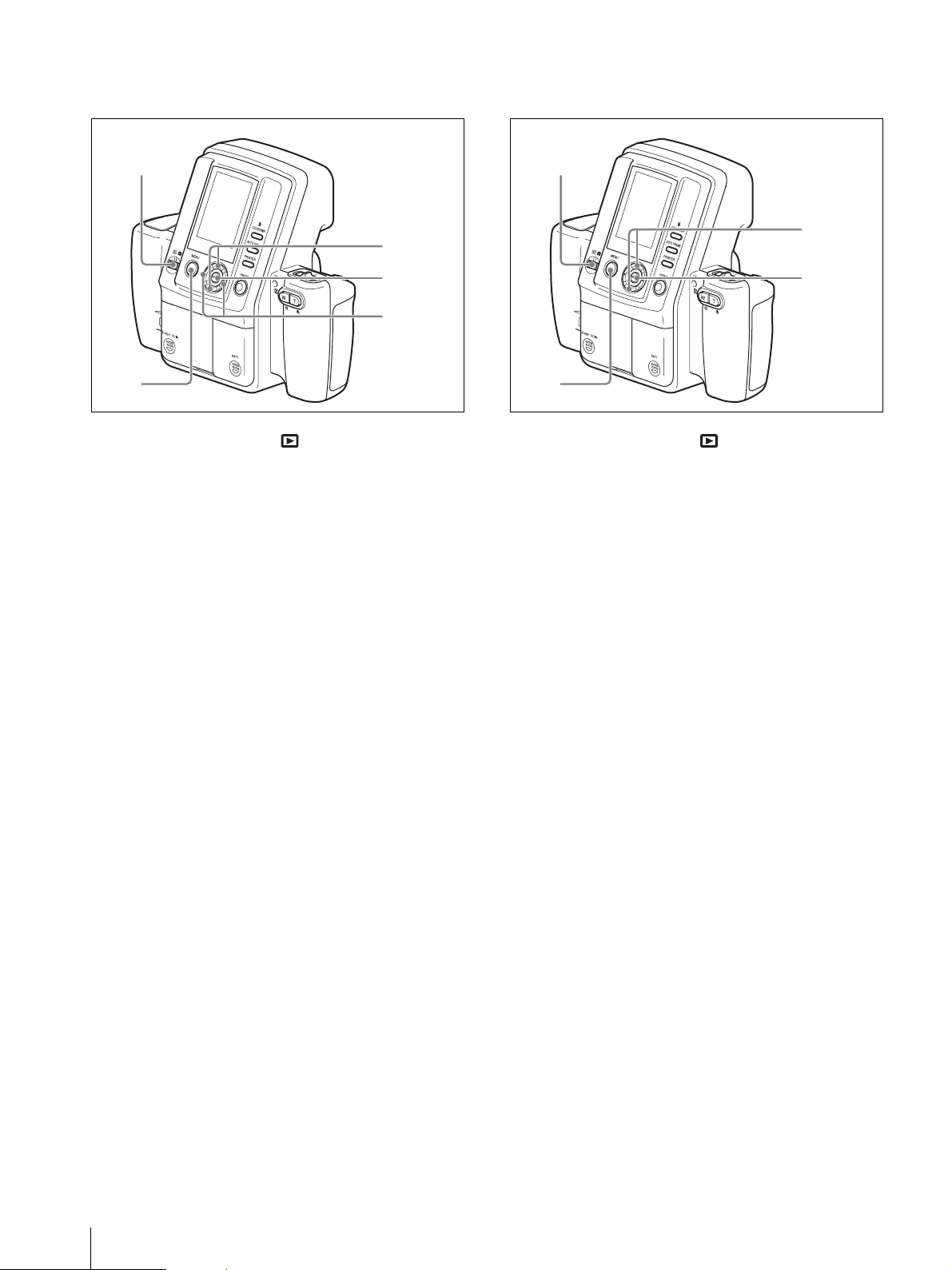
To delete individual pictures from the
menu screen
To delete all pictures from the menu
screen
1
2
1
Set the mode switch to .
2
Press the MENU button.
The menu screen appears.
3
Select DELETE by pressing the v or V control
button.
4
Press the ENTER button.
The DELETE screen appears.
3, 6
4, 7
5
1
2
1
Set the mode switch to .
2
Press the MENU button.
The menu screen appears.
3
Select DELETE ALL by pressing the v or V
control button.
4
Press the ENTER button.
The DELETE ALL screen appears.
3, 5
4, 6
5
Select a picture to delete by pressing the b or B
control button.
6
Select OK by pressing the v control button.
7
Press the ENTER button.
The selected picture is deleted from the memory.
To continue deleting pictures
Repeat steps 5 to 7 above.
5
Select OK by pressing the v control button.
6
Press the ENTER button.
All pictures are deleted from the memory.
To cancel picture deletion
Select CANCEL on the DELETE screen, and then press
the ENTER button. The Playback menu reappears.
To exit picture deletion
Press the MENU button.
26
Operations (Shooting and Printing)
Page 27
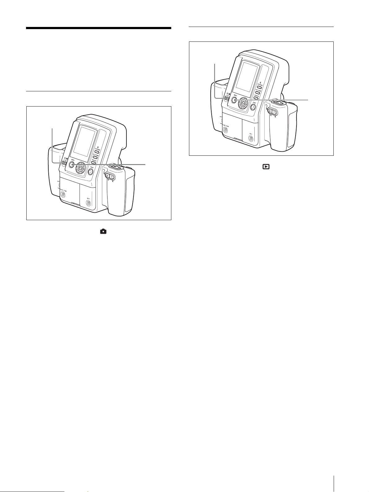
Settings
There are three types of camera menus: the Shooting
menu for setting shooting conditions, the Playback
menu for settings related to captured images, and the
SETUP menu for configuring the camera itself.
Displaying the Playback Menu
1
Displaying the Shooting Menu
1
1
Set the mode switch to .
2
Press the MENU button.
The Shooting menu appears.
To exit the menu and return to the
previous screen
Press the MENU button.
2
1
Set the mode switch to .
2
Press the MENU button.
The Playback menu appears.
To exit the menu and return to the
previous screen
Press the MENU button.
2
Settings
27
Page 28
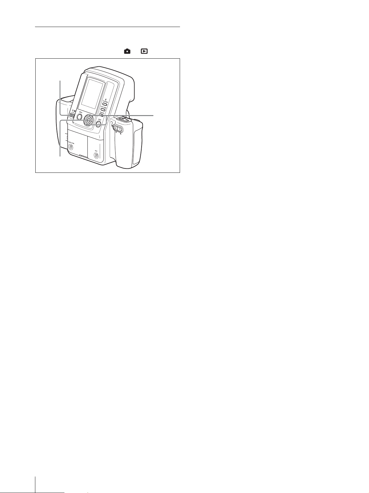
Displaying the SETUP Menu
The SETUP menu can be displayed regardless of
whether the mode switch is set to or .
1
2
3
1
Press the MENU button.
Depending on the mode switch position, the
shooting menu or playback menu appears.
2
Select SETUP by pressing the v or V control
button.
3
Press the ENTER button.
The SETUP menu appears.
To exit the menu and return to the
previous screen
Press the MENU button.
28
Settings
Page 29
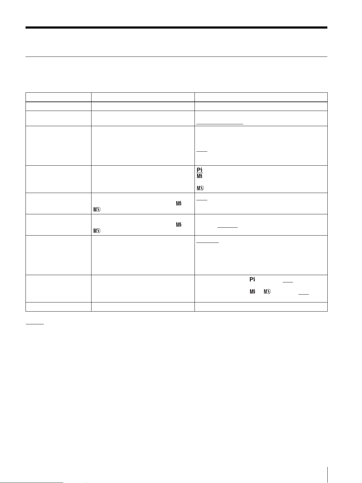
Menu
Functions of the Menu Items
Shooting menu
Menu Item Function Settings
EXIT Exits Menu mode. —
RESOLUTION Selects the resolution for recording. HIGH (3264 × 2448)
AUTO ERASE Sets the auto erase mode. ON
FLASH MODE Selects the flash mode.
APERTURE Selects the aperture setting.
Valid only when Flash Mode is set to or
.
SHUTTER Selects the shutter speed.
Valid only when Flash Mode is set to or
.
W.B. Adjusts the white balance. Program
EXPOSURE Specify the exposure compensation. When the flash mode is : –2.0EV to 0EV
SETUP To display the SETUP menu. (For details, see “SETUP menu” on page 30.)
STD (1632 × 1224)
When memory becomes full, data is deleted in order from
the oldest when new picture data is stored.
OFF
When memory becomes full, pictures can no longer be
taken.
Flash: Auto
Flash: Forced (flash intensity level: 100/70/50/35/25/18/
12%)
Flash: OFF
F4.7
F5.6
1/2[s], 1/4[s], 1/8[s], 1/15[s], 1/30[s], 1/60[s], 1/100[s],
1/125[s], 1/250[s]
: White balance is adjusted automatically.
One Push: Allows you to capture any image to use as the
reference value for white.
3000K, 3500K, 4000K, 4500K, 5000K, 5500K, 6000K,
6500K, 7000K: White balance is adjusted for the selected
color temperature.
1/4EV steps)
When the flash mode is or : –1.0EV to 0EV
+2.0EV (in 1/4EV steps)
, 1/500[s], 1/750[s], 1/1000[s]
to +2.0EV (in
to
: Default setting
MENU Lock: Press and hold the MENU button to lock or unlock the menu.
Menu
29
Page 30
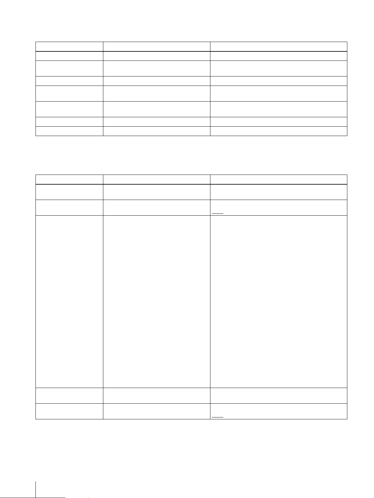
Playback menu
Menu Item Function Settings
EXIT Exits the menu mode. —
PROPERTY To display the information on the selected
image.
DELETE To delete a picture stored in memory. —
DELETE ALL To delete all pictures except the protected
DELETE ONE FROM
QUEUE
CLEAR QUEUE Removes all images from the print queue. —
SETUP Displays the SETUP menu. (For details, see “SETUP menu” on page 30.)
ones stored in memory.
Removes the selected image from the print
queue.
—
—
—
MENU Lock: Press and hold the MENU button to lock or unlock the menu.
SETUP menu
Menu Item Function Settings
RETURN Exits SETUP mode and returns to the
previous Menu display.
PRINT QUEUE MODE Enables/disables the print queue function. ON
ID PHOTO FRAME Selects the ID photo frame shown on the
LCD when the print preview screen is
displayed.
The ID photo frames that can be used with
this system are indicted to the right, but are
subject to change without notice.
CUSTOM FRAME Allows you to create and register up to five
additional ID photo frames of any size.
DIE-CUT MODE Enables/disables the die-cut printing
function.
—
OFF
SELECT ALL
DESELECT ALL
Custom-1
Custom-2
Custom-3
Custom-4
Custom-5
USA: Passport
CAN: Passport
MEX: Passport
COL: Passport
VEN: Passport
EU: Passport
GBR: Passport
DEU: Passport
FRA: Passport
ITA: Passport
NLD: Passport
ESP: Passport
AUT: Passport
RUS: Passport
TUR: Passport
AUS: Passport
NZL: Passport
JPN: Passport
JPN: Driver License
JPN: Personal History
—
ON
OFF
30
Menu
Page 31
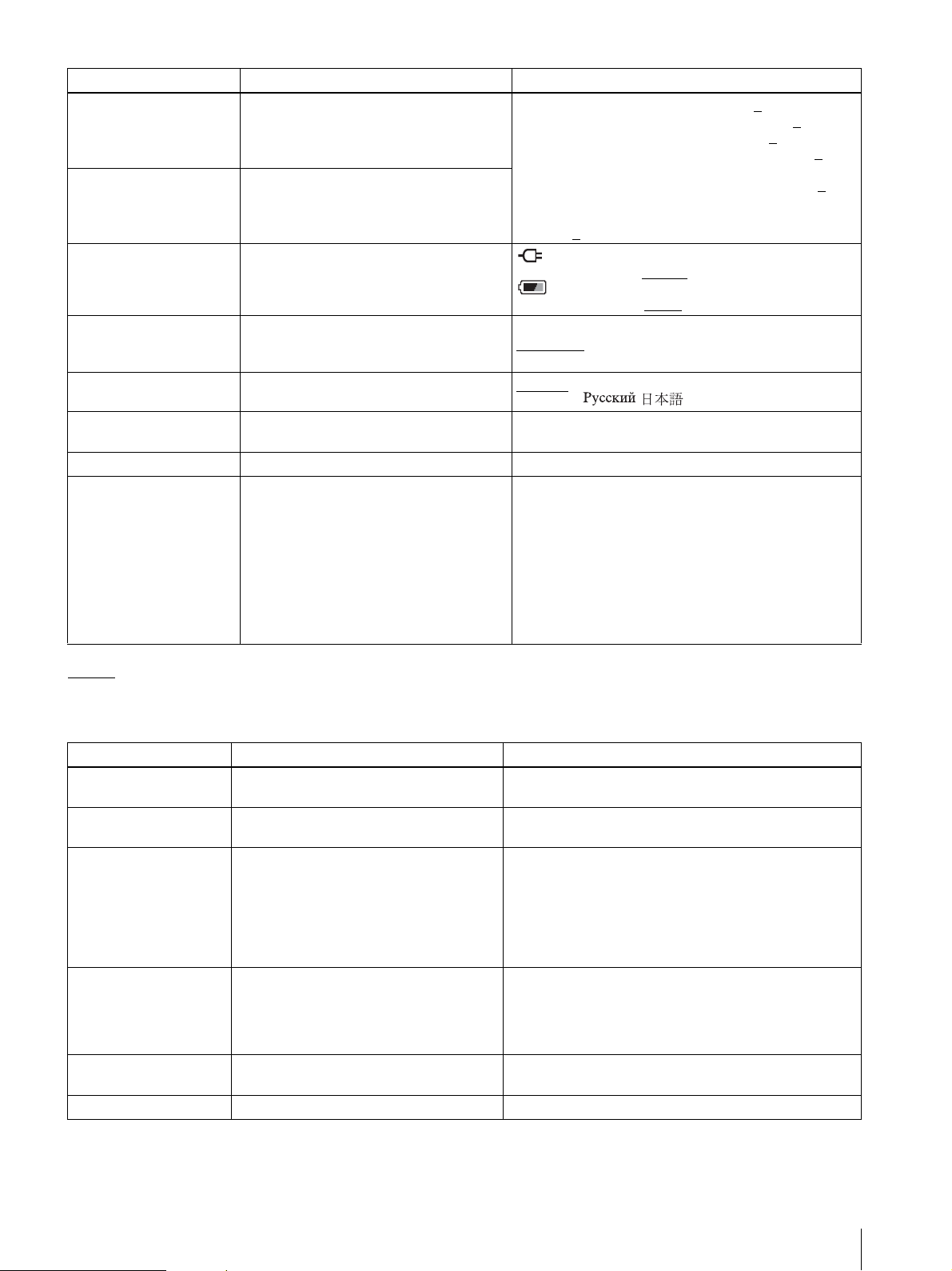
Menu Item Function Settings
COLOR ADJUST Adjusts the print quality for color pictures. CYN-RED: Adjusts cyan and red. (–7 to 0 to +7)
MAG-GRN: Adjusts magenta and green. (–7 to 0 to +7)
YEL-BLU: Adjusts yellow and blue. (–7 to 0
DARK: Adjusts the brightness of dark areas. (–7 to 0
B&W ADJUST Adjusts the print quality for black & white
pictures.
AUTO POWER SAVE Allows you to set or disable the AUTO
POWER SAVE function.
SOUND Turns the operation sound on or off. ON
LANGUAGE Selects the language. English
DEFAULT SETTING Returns camera settings to their default
values.
FIRMWARE VERSION Displays the camera version. —
Bluetooth To set for the Bluetooth functions. PROPERTY: Shows the camera’s address and passkey, and
+7)
LIGHT: Adjusts the brightness of light areas. (–7 to 0
+7)
SHARPNESS: Adjusts the sharpness of object contours.
power adapter use. (30 min
battery use. (10 min/7 min
SHUTTER
OFF
Portugêus / /
—
the list of the registered printers.
CHANGE PASSKEY: For changing the passkey, from
0000 to 9999.
ADD PRINTER: For registering optional printers up to
three.
REMOVE PRINTER: For removing a registered printer
one by one.
MODULE: For turning ON or OFF the power of the
Bluetooth circuit.
to +7)
(–7 to 0
: Sets the AUTO POWER SAVE function during AC
: Sets the AUTO POWER SAVE function during
/Deutsch/Français/Italiano/Español/Nederlands/
/10 min/DISABLE)
/3 min)
to +7)
to
to
: Default setting
Printer
Menu item Function Settings
COLOR ADJUST
COLOR
COLOR ADJUST
B&W
Bluetooth SETTING You can make Bluetooth settings. Bluetooth ADDR: The Bluetooth address is displayed.
PRINT SETTING Fine tunes the printing position for the UPC-
COPY PRINT Reprints the last picture stored in memory. [1 – 9]
TOTAL PRINTS Displays the total number of sheets printed. —
Adjusts the print quality for color pictures. Not used with this system.
Adjusts the print quality for black & white
pictures.
X46 series print paper.
Not used with this system.
PASSKEY INPUT: A passkey is set or changed.
MY DEVICE NAME: The printer can be assigned a number.
CONNECTION RECORD: The connection record is
displayed.
MODULE POWER: The power of the Bluetooth circuits is
turned on or off.
PRINT OFFSET (–2/–1/0/1/2)
The printing position can be adjusted in units of
0.5 mm (1/32").
PRINT TEST
Prints a color pattern.
Sets the number of sheets to reprint.
Menu
31
Page 32
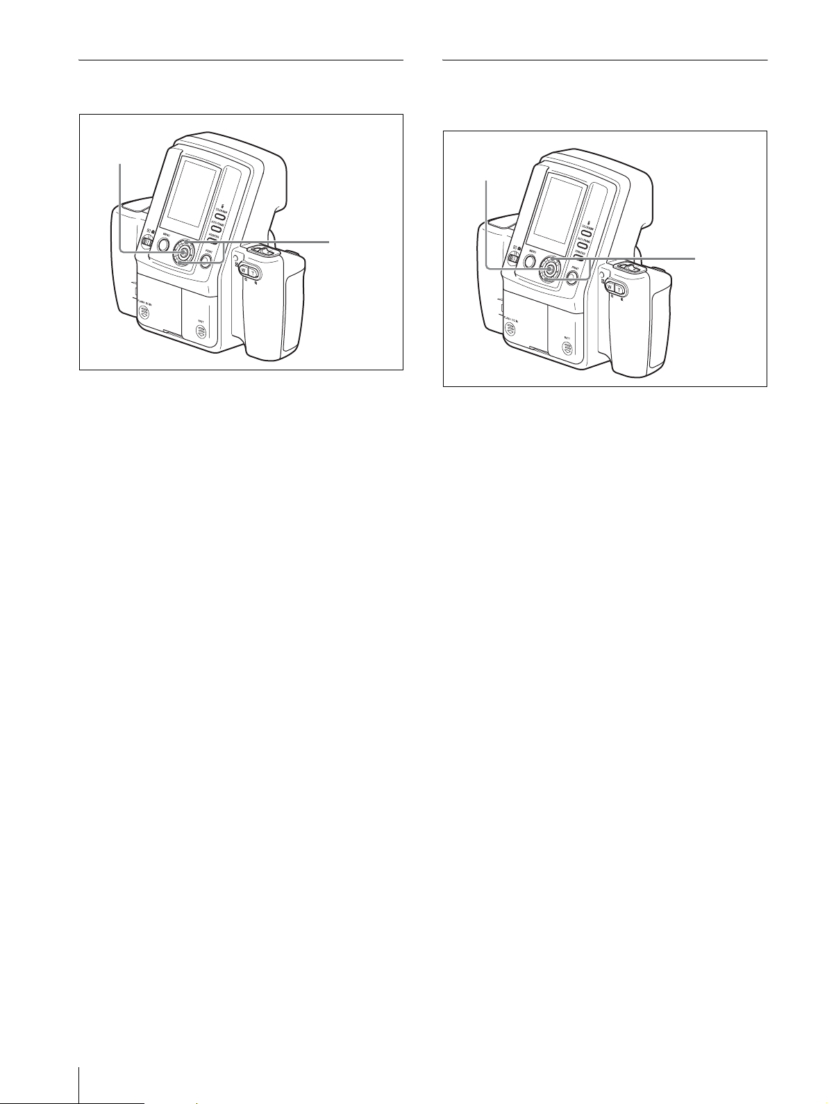
Setting the Image Resolution
Setting the Auto Erase Mode
Select the optimal image resolution for your print size.
3, 5
2, 4
1
Display the Shooting menu.
For details on displaying the menu screen, see
“Displaying the Shooting Menu” on page 27.
2
Select RESOLUTION by pressing the v or V
control button.
3
Press the ENTER button.
The RESOLUTION screen appears.
4
Select one of the following resolutions by pressing
the v or V control button.
HIGH: 3264 × 2448 (approximately 30 pictures
can be taken)
STD: 1632 × 1224 (approximately 120 pictures can
be taken)
Under normal circumstances, the number of
pictures listed above for each resolution can be
taken, but the number may decrease if pictures
containing complex patterns are included. In
Shooting mode, refer to the value displayed at the
top right of the LCD.
You can select the action performed by the camera when
the memory is full.
3, 5
2, 4
1
Display the Shooting menu.
For details on displaying the menu screen, see
“Displaying the Shooting Menu” on page 27.
2
Select AUTO ERASE by pressing the v or V
control button.
3
Press the ENTER button.
The AUTO ERASE screen appears.
4
Select ON or OFF by pressing the v or V control
button.
ON: When the memory is full, stored images are
deleted automatically starting with the oldest,
and new image data is stored.
OFF: Shooting is disabled when the memory is
full.
5
Press the ENTER button.
The Shooting menu reappears.
32
5
Press the ENTER button.
The Shooting menu reappears.
Menu
Page 33
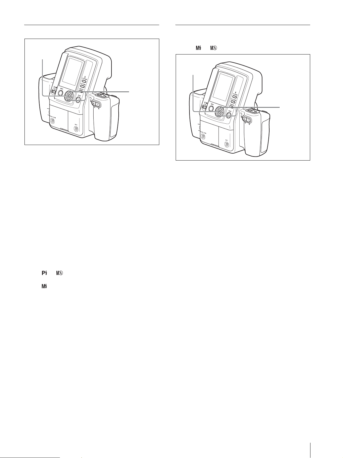
Selecting the Flash Mode
3, 5
1
Display the Shooting menu.
Setting the Aperture
You can only set the aperture when the FLASH MODE
is set to or .
3, 5
2, 4
2, 4
For details on displaying the menu screen, see
“Displaying the Shooting Menu” on page 27.
2
Select FLASH MODE by pressing the v or V
control button.
3
Press the ENTER button.
The FLASH MODE screen appears.
4
Select the flash mode by pressing the v or V
control button.
For details on each mode, see “Flash Modes and
Example Shooting Conditions” on page 7.
5
Press the ENTER button.
If or was selected for the flash mode, the
Shooting menu reappears.
If was selected for the flash mode, the menu for
selecting the flash intensity level appears. Select a
flash intensity level (100/70/50/35/25/18/12%)
using the v or V control button, and press the
ENTER button. The flash intensity level is set, and
the Shooting menu reappears.
1
Display the Shooting menu.
For details on displaying the menu screen, see
“Displaying the Shooting Menu” on page 27.
2
Select APERTURE by pressing the v or V control
button.
3
Press the ENTER button.
The APERTURE screen appears.
4
Select F 4.7 or F 5.6 by pressing the v or V control
button.
5
Press the ENTER button.
The Shooting menu reappears.
Menu
33
Page 34
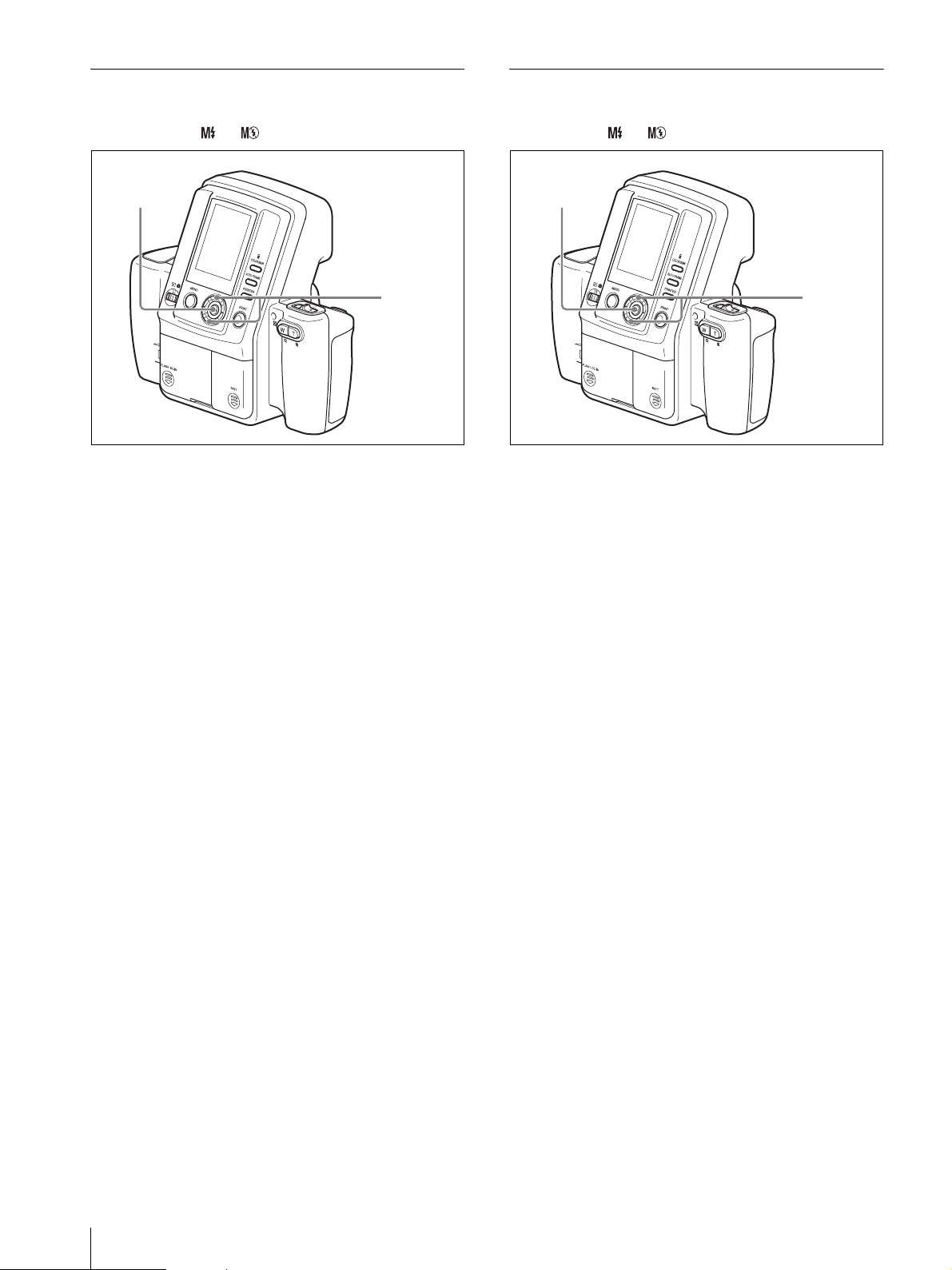
Setting the Shutter Speed
Adjusting the White Balance
You can only set the shutter speed when the FLASH
MODE is set to or .
3, 5
2, 4
1
Display the Shooting menu.
For details on displaying the menu screen, see
“Displaying the Shooting Menu” on page 27.
2
Select SHUTTER by pressing the v or V control
button.
3
Press the ENTER button.
The SHUTTER screen appears.
4
Select a shutter speed by pressing the v or V
control button.
Select from 1/2 (s), 1/4 (s), 1/8 (s), 1/15 (s),
1/30 (s), 1/60 (s), 1/100 (s), 1/125 (s), 1/250 (s), 1/
500 (s), 1/750 (s), or 1/1000 (s).
5
Press the ENTER button.
The Shooting menu reappears.
You can only set the white balance when the FLASH
mode is set to or .
3, 5
2, 4
1
Display the Shooting menu.
For details on displaying the menu screen, see
“Displaying the Shooting Menu” on page 27.
2
Select W.B. by pressing the v or V control button.
3
Press the ENTER button.
The W.B. screen appears.
4
Select the method for adjusting the white balance
by pressing the v or V control button.
PROGRAM: The white balance is adjusted
automatically.
OnePush: A new image is captured as the
reference value for white. Under the same
lighting conditions that you use for taking
pictures, display a white object (such as a piece
of paper or cloth) in the center of the LCD, and
then press the release button or the ENTER
button. The white balance is captured and
adjusted for the current lighting conditions.
3000K to 7000K: Select a color temperature to suit
the lighting conditions. You can select color
temperatures between 3000K and 7000K in
units of 500K. The white balance is adjusted
according to the selected color temperature.
34
Menu
5
Press the ENTER button.
The selected white balance setting is saved, and the
Shooting menu reappears.
Page 35
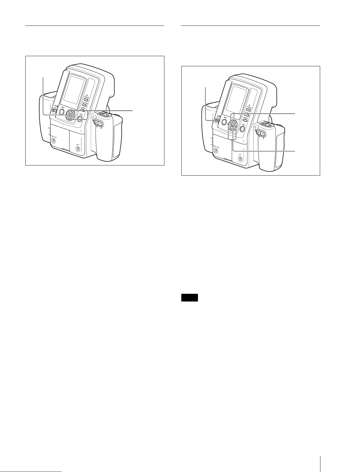
Compensating the Exposure
Viewing Information on Captured
You can set a default value for exposure compensation
during shooting.
3, 5
2, 4
1
Display the Shooting menu.
For details on displaying the menu screen, see
“Displaying the Shooting Menu” on page 27.
2
Select EXPOSURE by pressing v or V of the
control button.
3
Press ENTER of the control button.
The EXPOSURE display appears.
4
Select an appropriate value by pressing v or V of
the control button.
5
Press the ENTER button.
Images
You can view information about captured images,
including FLASH mode settings, on the LCD.
4
2
3
1
Display the Playback menu.
For details on displaying the menu screen, see
“Displaying the Playback Menu” on page 27.
2
Select PROPERTY by pressing the v or V control
button.
3
Press the ENTER button.
The PROPERTY screen appears.
You can select images by pressing the b or B
control button.
4
Press the MENU or ENTER button.
The Playback menu reappears.
The selected value is set, and the Shooting menu
reappears.
To compensate the exposure easily
The exposure can easily be changed by pressing v or V
of the control button. When the button is pressed, the
value displayed on the LCD changes.
Using this method, you can change the exposure even
when the menu has been locked.
For details on the menu lock, see “Locking the Camera
Menus” on page 43.
Note
Printing cannot be performed from the PROPERTY
screen. Return to the Playback mode display to perform
printing.
Menu
35
Page 36
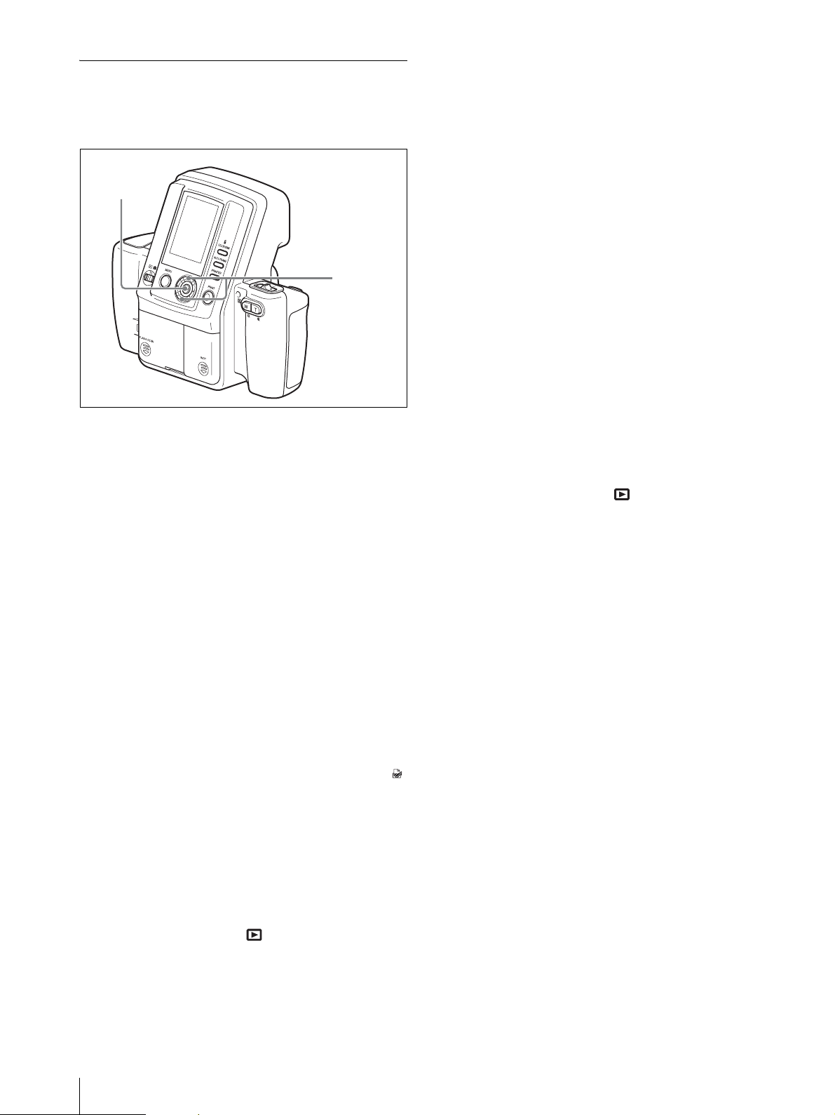
Using the Print Queue Function
This system provides a print queue function to print later
a group of captured images. To use this function, follow
the procedure below to enable the print queue function.
3, 5
2, 4
1
Display the SETUP menu.
For details on how to display this menu, see
“Displaying the SETUP Menu” on page 28.
2
Press the v or V control button to select PRINT
QUEUE MODE.
3
Select DELETE ONE FROM QUEUE by pressing
the v or V control button.
4
Press the ENTER button.
The Delete One from Queue screen appears.
5
Display the image that you want removed from the
print queue by pressing the b or B control button.
6
Select OK by pressing the v control button.
7
Press the ENTER button.
The image selected in step 5 is removed from the
print queue.
To continue removing images from the print
queue
Repeat steps 5 to 7 above.
To remove all images from the print
queue
You can simultaneously remove all images from the
print queue by performing the following steps.
1
Set the mode switch to .
2
Display the Playback menu.
3
Press the ENTER button.
The PRINT QUEUE MODE screen appears.
4
Press the v or V control button to select ON.
5
Press the ENTER button.
The SETUP menu returns.
About shooting and printing when the
print queue function is enabled
Once the camera’s print queue function is enabled, all
subsequently captured images are set with a print queue
flag. When these images are viewed in playback, the
icon appears on the LCD. When they are printed, all
images with the print queue flag are printed.
To remove images from the print queue
one by one
To remove an image from the print queue, perform the
following steps to remove its print queue flag.
1
Set the mode switch to .
For details on displaying the menu, see
“Displaying the Playback Menu” on page 27.
3
Select CLEAR QUEUE by pressing the v or V
control button.
4
Press the ENTER button.
The Clear Queue screen appears.
5
Select OK by pressing the v control button.
6
Press the ENTER button.
All images are removed from the print queue.
36
2
Display the Playback menu. For details on
displaying the menu, see “Displaying the Playback
Menu” on page 27.
Menu
Page 37
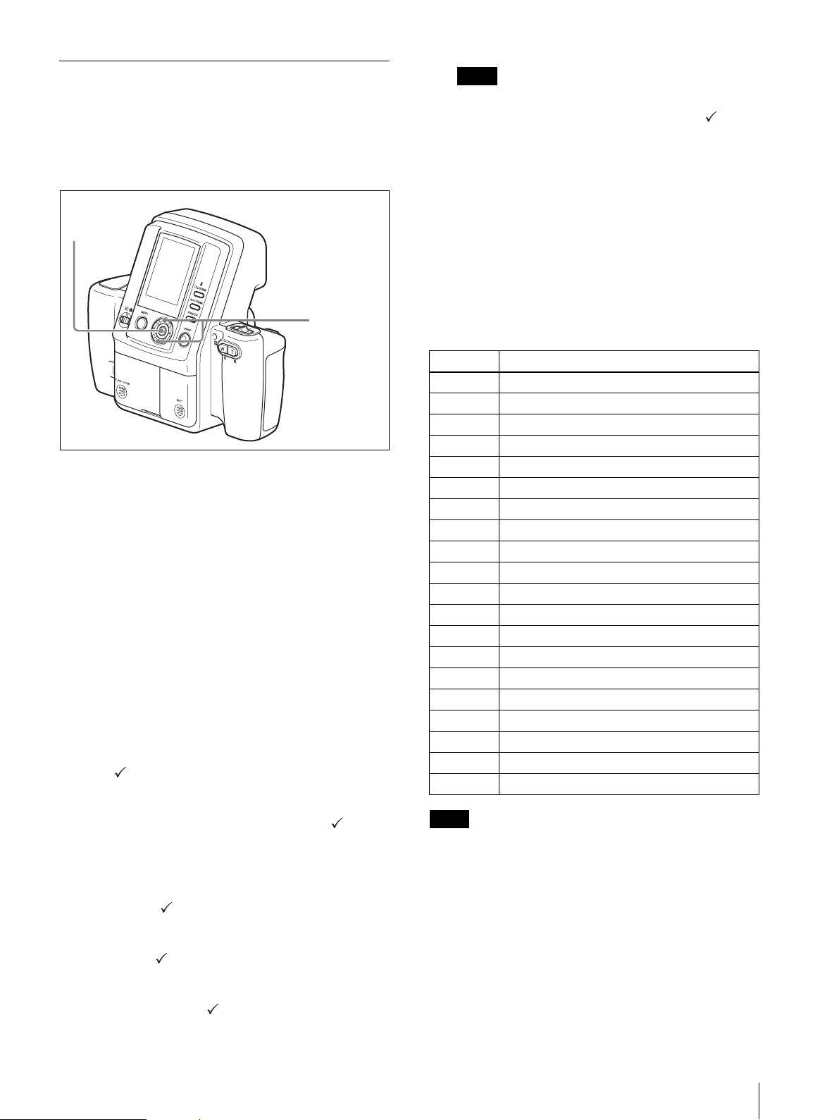
Setting up a Frame for Display During Printing
The ID photo frame available for selection on the print
preview screen can be set in the SETUP menu. Set the
most frequently used frames to display so that you can
select the desired frame easily.
Note
Select at least one ID photo frame. You cannot close
the ID PHOTO FRAME screen when the of all
ID photo frames are deleted.
6
When you have finished configuring the settings,
select RETURN by pressing the v or V control
button.
3, 5, 7
2, 4, 6
1
Display the SETUP menu.
For details on displaying this menu, see
“Displaying the SETUP Menu” on page 28.
2
Select ID PHOTO FRAME by pressing the v or V
control button.
3
Press the ENTER button.
The ID PHOTO FRAME screen appears.
4
Select a frame to hide by pressing the v or V
control button.
You can display the next page or return to a
previous page by pressing the b or B control
button.
5
Press the ENTER button.
The (check mark) for the selected frame appears,
and the frame becomes available in the print
preview screen.
If you press the ENTER button again, the (check
mark) is removed, and the frame will not be
available in the print preview screen.
Each press of the ENTER button removes or
restores the mark.
7
Press the ENTER button.
The SETUP menu reappears.
Country code example of ID photo frame
The ID photo frame of this camera uses the following
ISO country codes, regardless of the language selected.
Code Country
AUS Australia
AUT Austr ia
BRA Brazil
CAN Canada
COL Columbia
DEU Germany
ESP Spain
EU EU
FRA France
GBR United Kingdom
ITA Italy
JPN Japan
MEX Mexico
NLD Netherland
NZL New Zealand
PRT Portugal
RUS Russia
TUR Turkey
USA USA
VEN Venezuela
Note
Depending on your country and region selection during
initial configurations, ID photo frames for some
countries may not be available for selection.
If you select SELECT ALL and press the ENTER
button, the mark appears for all of the ID photo
frames.
If you select DESELECT ALL and press the
ENTER button, the mark is removed for all of
the ID photo frames.
Menu
37
Page 38
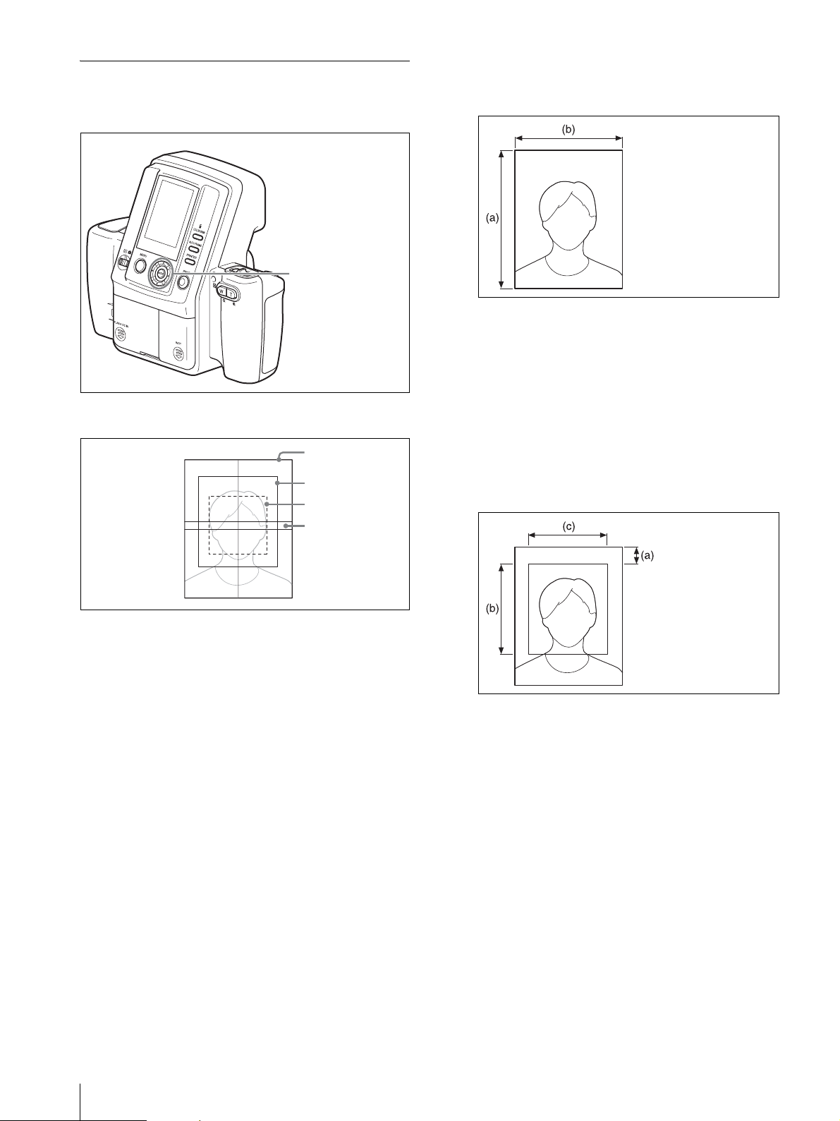
Creating an Additional Frame
You can define up to five ID photo frames of any size
and then register them on this camera.
6
Specify a photo size.
Press the v or V control button to select the next
setting item, and then press b or B to select a value.
2, 3, 4, 5,
6, 7, 8, 9,
10, 11, 12
,
14
When creating an additional frame, define the following
frame.
Photo size
Maximum face size
Minimum face size
Eye area
1
Display the SETUP menu.
For details on how to display this menu, see
“Displaying the SETUP Menu” on page 28.
(a) Height
(b) Width
SIZE UNIT: Select a size unit.
Height: Specify the height of the photo size.
Width: Specify the width of the photo size.
7
Press the V control button to select NEXT, and then
press the ENTER button.
The 3rd screen of the Frame Setting screen appears.
8
Specify the maximum face size (maximum range to
cover the face of the subject).
Press the v or V control button to select the next
setting item, and then press b or B to select a value.
(a) Offset
(b) Height
(c) Width
38
2
Press the v or V control button to select CUSTOM
FRAME.
3
Press the ENTER button.
The 1st screen of the Frame Setting screen appears.
4
Press the b or B control button to select a frame
number (1 to 5).
5
Press the V and B control buttons in that order to
select NEXT, and then press the ENTER button.
The 2nd screen of the Frame Setting screen
appears.
Menu
Offset: Specify the distance from the frame
circumference to the maximum face area.
Height: Specify the height of the maximum face
size.
Width: Specify the width of the maximum face
size.
9
Press the V control button to select NEXT, and then
press the ENTER button.
The 4th screen of the Frame Setting screen appears.
Page 39
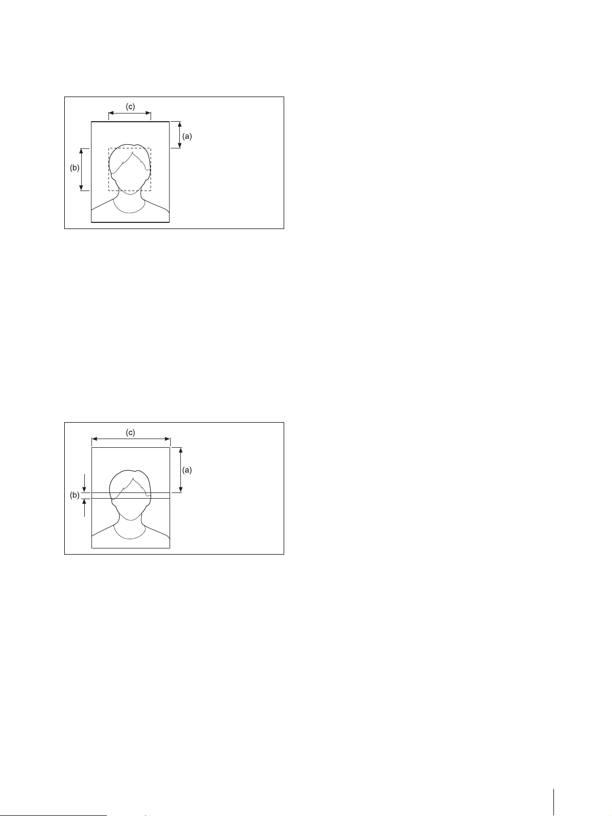
10
Specify the minimum face size (minimum range to
cover the face of the subject).
Press the v or V control button to select the next
setting item, and then press b or B to select a value.
(a) Offset
(b) Height
(c) Width
Offset: Specify the distance from the frame
circumference to the minimum face size.
Height: Specify the height of the minimum face
size.
Width: Specify the width of the minimum face
size.
11
Press the V control button to select NEXT, and then
press the ENTER button.
The 5th screen of the Frame Setting screen appears.
15
Press the b or B control button to select OK, and
then press the ENTER button.
The SETUP menu returns.
To return to a previous screen during
configuration
You can return to a previous screen and change settings
at any time during screens 2 through 6 of the Frame
Settings screen. To return to a previous screen, press the
v control button to select PREV, and then press the
ENTER button.
Using an additional frame
You can use the ID PHOTO FRAME list to enable
additional frame. For details, see “Setting up a Frame for
Display During Printing” on page 37.
12
Specify the eye area (area where the eyes of the
subject are positioned).
Press the v or V control button to select the next
setting item, and then press b or B to select a value.
(a) Offset
(b) Height
(c) Width
Offset: Specify the distance from the frame
circumference to the eye area.
Height: Specify the height of the eye area.
Width: Specify the width of the eye area.
13
Press the V control button to select NEXT, and then
press the ENTER button.
The 6th screen of the Frame Setting screen appears.
14
Check the items you have specified so far.
To change a setting, press the v control button to
select PREV, and then press the ENTER button to
return to the previous screen.
Menu
39
Page 40
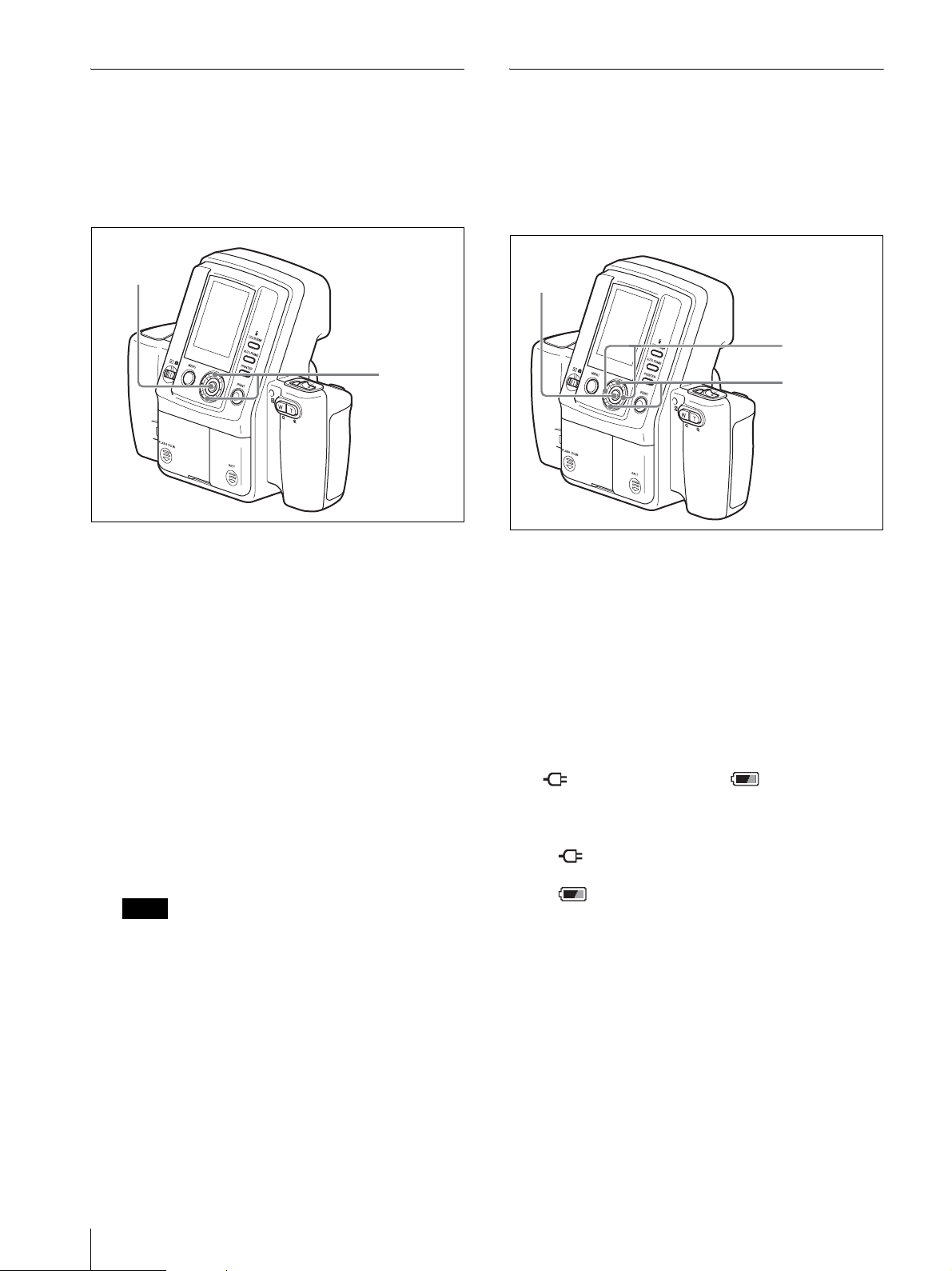
Using the Die-cut Print Function
Using the Auto Power Save
The die-cut print function allows you to print a captured
image at a size about 3 mm larger than the selected
frame size so that it becomes the target size when the
image is cut. (This is call “die-cut print”.) To use this
function, follow the steps below to enable the die-cut
mode.
3, 5
2, 4
1
Display the SETUP menu.
For details on how to display this menu, see
“Displaying the SETUP Menu” on page 28.
Function
When you enable the auto power save function, the
camera enters power save mode if no operation is
performed within a certain amount of time. The amount
of time can be set for when the AC power adaptor is used
as well as when batteries are used.
3, 7
5
2, 4, 6
1
Display the SETUP menu.
For details on how to display this menu, see
“Displaying the SETUP Menu” on page 28.
2
Press the v or V control button to select DIE-CUT
MODE.
3
Press the ENTER button.
The DIE-CUT MODE screen appears.
4
Press the v or V control button to select ON.
5
Press the ENTER button.
The SETUP menu returns.
From now on, captured images are printed to a size
about 3 mm larger than the selected ID photo frame
size.
Note
When the die-cut print function is enabled, the
number of images printed on a single sheet of paper
may be less than with normal printing.
2
Press the v or V control button to select AUTO
POWER SAVE.
3
Press the ENTER button.
The AUTO POWER SAVE screen appears.
4
Press the v or V control button and select either
(AC power adaptor) or (batteries).
5
Press the b or B control button and select the time
until the power save mode is activated.
If (AC power adaptor) is specified, you can
select 30min, 10min, or DISABLE.
If (batteries) are specified, you can select
10min, 7min, or 3min.
If you select DISABLE, the auto power save is
disabled.
6
Press the v or V control button to select OK.
7
Press the ENTER button.
The SETUP menu returns.
40
Menu
Page 41
Turning on the power again while in the
power save mode
Perform one of the following operations.
• Set the on/standby switch to 1 (standby), and then
back to ? (on) again.
• Press the release button halfway.
• Press any button on the camera.
Setting Camera Sounds
You can select whether the camera makes sounds when
it is operated.
3, 5
2, 4
1
Display the SETUP menu.
For details on displaying this menu, see
“Displaying the SETUP Menu” on page 28.
2
Select SOUND by pressing the v or V control
button.
3
Press the ENTER button.
The SOUND screen appears.
4
Select a sound setting by pressing the v or V
control button.
ON: A sound is emitted for all camera operations
(except zoom operations).
SHUTTER: A sound is emitted only when the
release or PRINT button is pressed.
OFF: No sounds are emitted.
5
Press the ENTER button.
The SETUP menu reappears.
Menu
41
Page 42
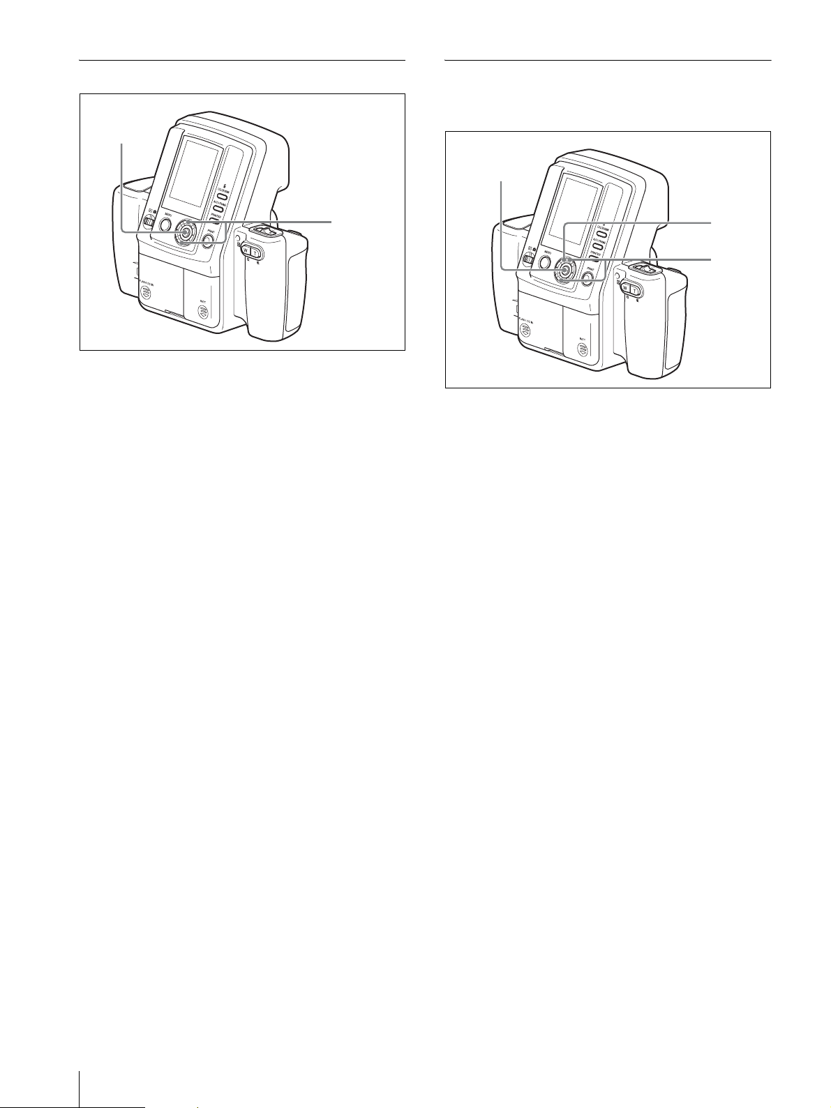
Selecting the Language Display
3, 5
Returning Settings to Defaults
You can return camera settings to their default factory
settings.
3, 5
2, 4
1
Display the SETUP menu.
For details on displaying this menu, see
“Displaying the SETUP Menu” on page 28.
2
Select LANGUAGE by pressing the v or V control
button.
3
Press the ENTER button.
The LANGUAGE screen appears.
4
Select a language display by pressing the v or V
control button.
You can select from English, German, French,
Italian, Spanish, Dutch, Polish, Russian, and
Japanese.
5
Press the ENTER button.
The SETUP menu reappears.
1
Display the SETUP menu.
For details on displaying this menu, see
“Displaying the SETUP Menu” on page 28.
2
Select DEFAULT SETTING by pressing the v or V
control button.
3
Press the ENTER button.
The DEFAULT SETTING screen appears.
4
Read the warning carefully, and select “OK” by
pressing the V control button.
5
Press the ENTER button.
The LANGUAGE screen appears.
All camera settings are returned to their default
factory settings, and the SETUP menu reappears.
(Captured images and additional frames are
retained.)
4
2
42
When all settings are returned to their factory
defaults, the default settings must be reconfigured
the next time you turn on the camera.
For details on default settings, see ““The first time
you turn on the camera (default setting)” on page
20.
Menu
Page 43
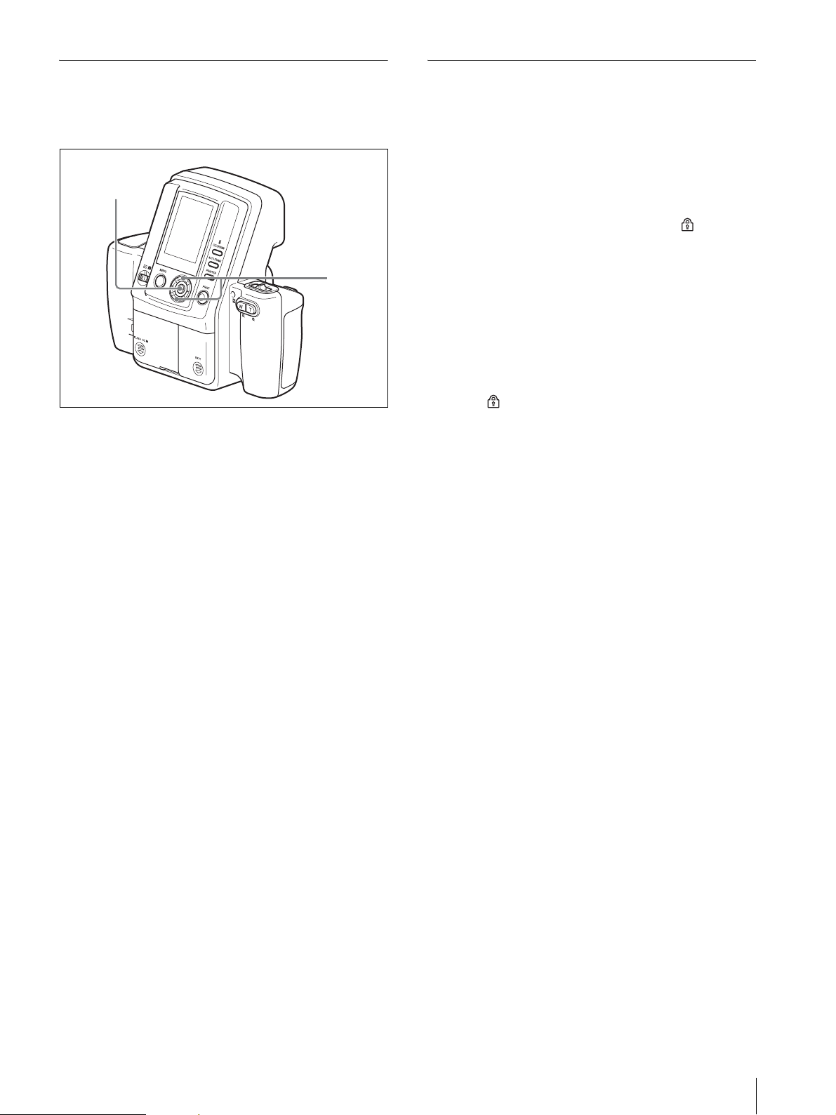
Displaying the Firmware Version
Locking the Camera Menus
You can display the camera’s firmware version. Use this
information when consulting a service representative
about the camera.
3, 4
2
1
Display the SETUP menu.
For details on displaying this menu, see
“Displaying the SETUP Menu” on page 28.
You can keep menu screens from displaying even when
the MENU button is pressed during Shooting or
Playback. This can prevent accidental changes to menu
settings.
To lock the menus
Press the MENU button for at least five seconds. The
menu screen disappears, and the lock icon appears.
This icon indicates that the menus are now locked and
pressing the MENU button will not display the menu
screen.
The menus remain locked even when you switch
between Shooting and Playback modes or restart the
camera.
To release the menu lock
Press the MENU button for at least five seconds. The
lock icon disappears, and the menu screen appears.
2
Select FIRMWARE VERSION by pressing the v
or V control button.
3
Press the ENTER button.
The FIRMWARE VERSION screen appears.
4
Press the ENTER button.
The SETUP menu reappears.
Menu
43
Page 44
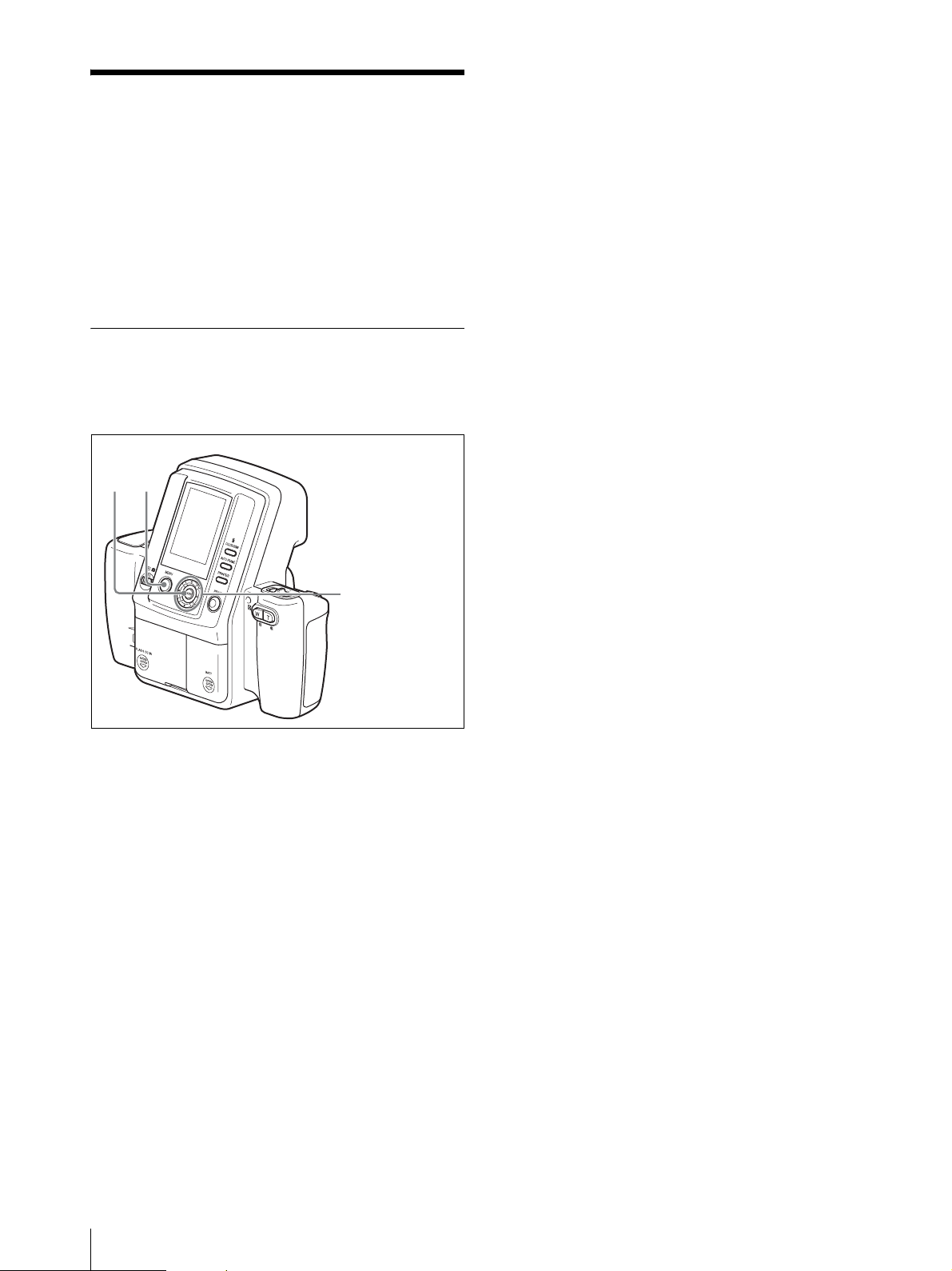
Adjusting the Print Quality
You can use the MENU function of the camera to adjust
the picture quality. The guide print function of the
camera enables you to check the adjustment results.
For details on the meanings of the values in the CYNRED, MAG-GRN, and YEL-BLU displays, see
“Explanation of Picture Quality Adjustment
Parameters” on page 45.
Adjusting the Picture Quality
To adjust the picture quality of color
prints
DARK: Pressing B increases the darkness in the
dark parts.
LIGHT: Pressing B increases the brightness in the
bright parts.
GAMMA: Pressing b makes the color tone of the
whole picture lighter, while pressing B makes
it deeper.
SHARPNESS: Pressing B makes the edges of
objects in the picture sharper.
5
Press the v or V control button to select OK, and
then press the ENTER button.
The Guide Print screen appears.
6
Press the v or V control button to select GUIDE
PRINT-RGB or GUIDE PRINT-DLGm, and then
press the ENTER button.
The guide picture is printed. The picture currently
being played back or the picture taken immediately
previous is used for the guide picture.
37
2, 4, 5, 6
1
Display the SETUP menu.
For details on how to display the menu, see
“Displaying the SETUP Menu” on page 28.
2
Press the v or V control button to select COLOR
ADJUST.
3
Press the ENTER button.
The COLOR ADJUST screen appears.
For details on the guide print function, see “Guide
Print Function” on page 47.
7
Press the MENU button.
The SETUP menu returns.
Check the guide picture printed in the previous
step. If necessary, repeat starting from step 2 and readjust the picture quality.
To adjust the picture quality of black & white
prints
After pressing the MENU button in step 2 of “To adjust
the picture quality of color prints,” press the V control
button. The camera enters the picture quality adjustment
mode for black & white prints and the B&W ADJUST
screen appears. The procedure for adjusting the picture
quality is the same as that for color prints.
4
Specify each adjustment item.
Press the v or V control button to select the next
adjustment item, and then press b or B to select a
value.
CYN-RED: Pressing b gives the picture more
MAG-GRN: Pressing b gives the picture more
YEL-BLU: Pressing b gives the picture more
44
Adjusting the Print Quality
cyan, while pressing B makes it more reddish.
magenta, while pressing B makes it more
greenish.
yellow, while pressing B makes it more bluish.
Page 45
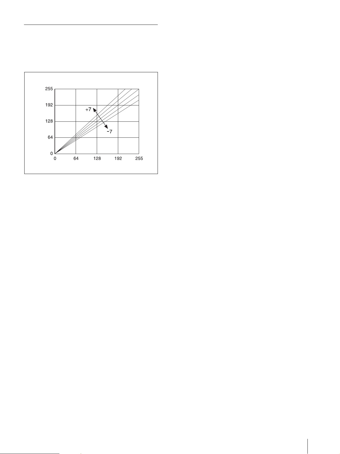
Explanation of Picture Quality Adjustment Parameters
Picture quality variations when the R, G,
and B parameters are changed
Figure 1
Light
Var iation
Level
Dark LightSubject
MAG-GRN adjustment (G parameter)
You can adjust the magenta and green color
components. The default is 0.
Pressing B on the control button of the printer changes
the value in the plus direction to 1, 2 … 7, making the
green component value in the picture increase in the
linear direction that the brightness increases as shown in
figure 1. This adds more green as if a green light has
been cast. However, the maximum effective brightness
value is 255. When the value becomes larger than 255,
saturation occurs. When this occurs, the saturated white
area remains white even if the value is increased further
in the plus direction.
Pressing b on the control button changes the value in the
minus direction to –1, –2 … –7, making the green
component value in the picture decrease in the linear
direction that the brightness decreases as shown in the
figure. Decreasing the brightness makes the green color
darker and reduces the greenness. The complementary
color magenta (reddish-purple) is added. In this case, the
white area becomes slightly magenta in color.
CYN-RED adjustment (R parameter)
You can adjust the cyan and red color components. The
default is 0.
Pressing B on the control button of the printer changes
the value in the plus direction to 1, 2 … 7, making the
red component value in the picture increase in the linear
direction that the brightness increases as shown in figure
1. This adds more red as if a red light has been cast.
However, the maximum effective brightness value is
255. When the value becomes larger than 255, saturation
occurs. When this occurs, the saturated white area
remains white even if the value is increased further in the
plus direction.
Pressing b on the control button changes the value in the
minus direction to –1, –2 … –7, making the red
component value in the picture decrease in the linear
direction that the brightness decreases as shown in the
figure. Decreasing the brightness makes the red color
darker and reduces the redness. The complementary
color cyan (light blue) is added. In this case, the white
area becomes bluish.
YEL-BLU adjustment (B parameter)
You can adjust the yellow and blue color components.
The default is 0.
Except for some special specifications, this adjustment
is not possible when B&W is selected.
Pressing B on the control button of the printer changes
the value in the plus direction to 1, 2 … 7, making the
blue component value in the picture increase in the
linear direction that the brightness increases as shown in
figure 1. This adds more blue as if a blue light has been
cast. However, the maximum effective brightness value
is 255. When the value becomes larger than 255,
saturation occurs. When this occurs, the saturated white
area remains white even if the value is increased further
in the plus direction.
Pressing b on the control button changes the value in the
minus direction to –1, –2 … –7, making the blue
component value in the picture decrease in the linear
direction that the brightness decreases as shown in the
figure. Decreasing the brightness makes the blue color
darker and reduces the blueness. The complementary
color yellow is added. In this case, the white area
becomes yellowish.
Adjusting the Print Quality
45
Page 46
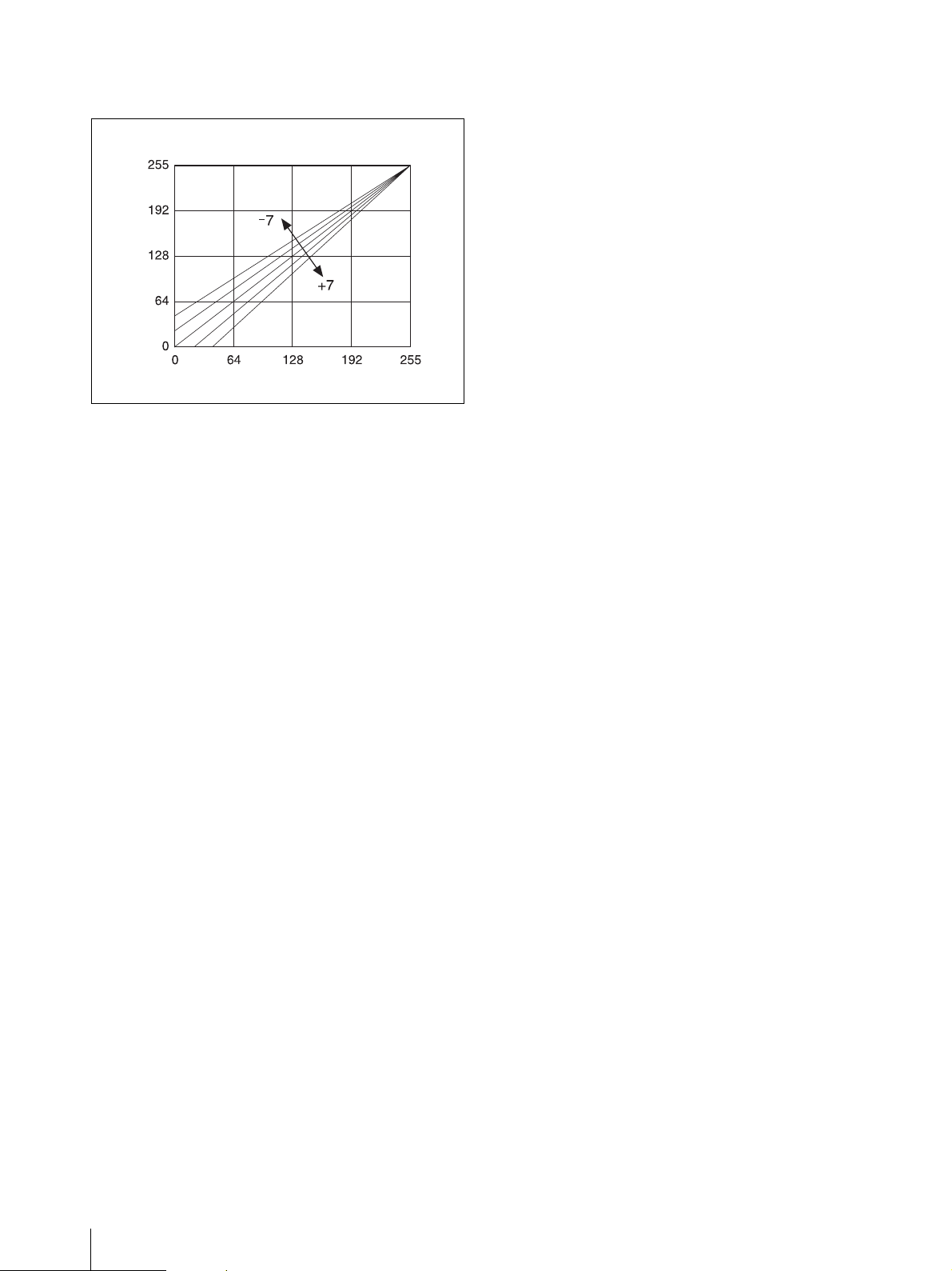
Picture quality variations when the D, L,
V
and Gm parameters are changed
Figure 2
Light
GAMMA adjustment (GM parameter)
You can adjust the gamma value. The default is 0.
Pressing B on the control button of the printer increases
the halftone of each of the RGB data in the direction that
the brightness increases.
Pressing b on the control button decreases the halftone
of each of the RGB data in the direction that the
darkness increases.
ariation
Level
LightSubjectDark
DARK adjustment (D parameter)
You can adjust the dark parts. The default is 0.
Pressing B on the control button of the printer changes
the value in the plus direction to 1, 2 … 7, making the
dark side of each of the RGB data increase
simultaneously in the linear direction that the depth
increases as shown in figure 2. This adds more depth.
However, the maximum effective darkness value is 0.
When the value becomes smaller than 0, saturation
occurs.
Pressing b on the control button changes the value in the
minus direction to –1, –2 … –7, making the dark side of
each RGB data lighter and decreasing the darkness.
LIGHT adjustment (L parameter)
You can adjust the light parts. The default is 0.
Pressing B on the control button of the printer
simultaneously changes the R, G, and B parameters as
shown in figure 1, making the light side of each of the
RGB data increase simultaneously in the linear direction
that the brightness increases. This gives an overexposed
quality to the picture.
Pressing b on the control button makes the light side of
each of the RGB data darker, and gives you a picture that
seems underexposed.
SHARPNESS
SHARPNESS adjustment is a function for adding
emphasis to edges in pictures. This function cannot be
used to increase the resolution. It is intended for
changing the sharpness.
SHARPNESS can be used as a parameter to improve
pictures, but increasing the sharpness too much will not
produce a natural picture. Generally, the default setting
is recommended. When a large print size is used and
SHARPNESS is set to a large value, picture quality does
appear to improve.
Contrast
In addition to the sharpness function, it is possible to add
sharpness to the image by adding the contrast of dark
and light. Contrast can be set using the DARK and
LIGHT items in the menu screen. Increasing the DARK
and LIGHT values in the plus direction increases the
contrast, and a high contrast image can be obtained. The
downside, however, is that increasing the contrast values
in the plus direction diminishes the amount of
information about white and black tones, and as a result,
the white and black gradation becomes coarser. Thus, an
appropriate contrast setting is required. We recommend
setting the contrast to +2 or +3.
SHARPNESS adjustment
You can adjust the sharpness of pictures.
Pressing B on the control button of the printer changes
the value in the plus direction from 0 to 1, 2 … 7, adding
emphasis to edges in pictures. We recommend setting a
small value when the print size is small.
46
Adjusting the Print Quality
Page 47
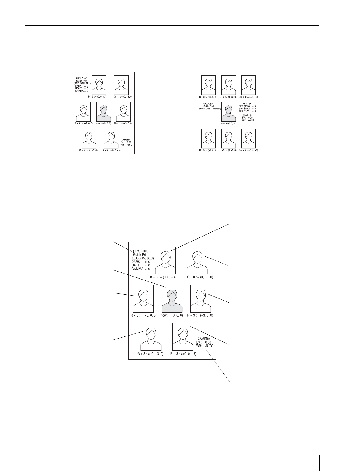
Guide Print Function
The Guide Print-RGB or Guide Print-DLGm layout
enables you to print a guide picture that has each of the
RGB or DLGm parameters changed.
Guide Print-RGB (adjusting RGB parameters)
Selecting the Guide Print-RGB layout enables a guide
picture (adjustment simulation) to be printed for the
RGB parameters. Since the picture used for printing is
the picture being played back on the camera, you can
actually adjust the picture quality while looking at the
Guide pictures can be printed on UPC-X46 series, and
UPC-X34 series paper.
The following is an example of a guide picture printout.
picture.
The picture in the center is printed using the current
color tone adjustment values. Six playback images of
differing color are printed around this picture.
The current state of each of the
DARK, LIGHT, and GAMMA
parameters is displayed for
reference.
This is a picture showing the current
state of the RED, GREEN, and
BLUE parameters.
This is a picture showing the RED
parameter decreased by 3 from the
current state.
The subject appears a little darker
than in the current picture, and
overall the picture appears slightly
cyan.
This is a picture showing the
GREEN parameter increased by 3
from the current state.
The white saturated parts remain
white and do not change. The
subject appears a little lighter than in
the current picture, and slightly
green.
The values below each of the pictures are for the R, G,
and B parameters. If, for example, you want to use the
color tone on the top left in the figure above, set the B
parameter to +3 because (RED, GREEN, BLUE) = (0, 0,
+3).
This is a picture showing the BLUE
parameter increased by 3 from the
current state.
The white saturated parts remain white
and do not change. The subject
appears a little lighter than in the
current picture, and slightly blue.
This is a picture showing the GREEN
parameter decreased by 3 from the
current state.
The subject appears a little darker than
in the current picture, and overall the
picture appears slightly magenta.
This is a picture showing the RED
parameter increased by 3 from the
current state.
The white saturated parts remain white
and do not change. The subject
appears a little lighter than in the
current picture, and slightly red.
This is a picture showing the BLUE
parameter decreased by 3 from the
current state.
The subject appears a little darker than
in the current picture, and overall the
picture appears slightly yellow.
Shooting conditions of the camera
If you want to adjust (RED, GREEN, BLUE) = (0, 0, +3)
further, set the B parameter to +3, and then print another
Guide Print-RGB. This will give you a simulation for
each color variation with (RED, GREEN, BLUE) = (0,
0, +3) in the center.
Adjusting the Print Quality
47
Page 48
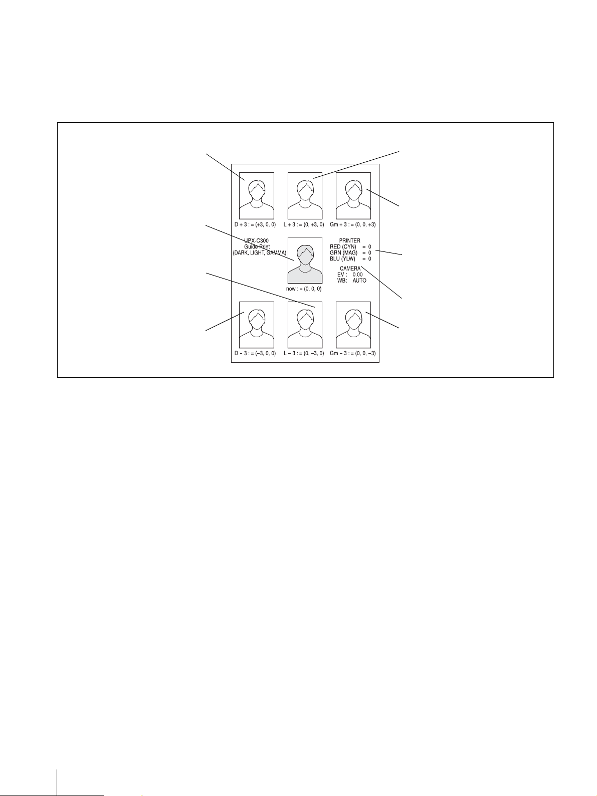
Guide Print-DLGm (adjusting DLGm parameters)
Selecting the Guide Print-DLGm layout enables a color
guide to be printed for the DLGm parameters. Since the
picture used for printing is the picture being played back
on the camera, you can actually adjust the picture quality
while looking at the picture.
The picture in the center is printed using the current
color tone adjustment values. Six playback images of
differing color are printed around this picture.
This is a picture showing the DARK
parameter increased by 3 from the
current state. With focus on the deep
parts, this has become a picture with
more depth than the current one.
This is a picture showing the current
state of the DARK, LIGHT, and
GAMMA parameters.
This is a picture showing the LIGHT
parameter decreased by 3 from the
current state. The light parts
become slightly darker than in the
current picture.
This is a picture showing the DARK
parameter decreased by 3 from the
current state. The deep parts
become lighter as if the picture was
taken in a bright place.
The values below each of the pictures are for the D, L,
and Gm parameters. If, for example, you want to use the
tone on the top left in the figure above, set the D
parameter to +3 because (DARK, LIGHT, GAMMA) =
(+3, 0, 0).
If you want to adjust (DARK, LIGHT, GAMMA) = (+3,
0, 0) further, set the D parameter to +3, and then print
another Guide Print-DLGm. This will give you a
simulation picture for each parameter variation with
(DARK, LIGHT, GAMMA) = (+3, 0, 0) in the center.
This is a picture showing the LIGHT
parameter increased by 3 from the
current state.
The light parts become lighter than
in the current picture.
This is a picture showing the
GAMMA parameter increased by 3
from the current state. The halftones
become slightly darker than in the
current picture.
The current state of each of the
RED, GREEN, and BLUE
parameters is displayed for
reference.
Shooting conditions of the camera
This is a picture showing the
GAMMA parameter decreased by 3
from the current state.
The halftones become slightly lighter
than in the current picture.
Advice on adjusting color tones
The guide print function gives you a rough guide as to
how to adjust the color tone. However, if you understand
the following, you can use this function to its full
potential.
The guide print can also be used for black & white
prints. Black & white pictures printed with this system
are printed by overlaying the three colors cyan, magenta,
and yellow to express gray. Therefore, a perfectly
achromatic picture may not be obtained and colors may
sometimes be visible. A black & white guide print can
be used to adjust the balance of these three colors.
48
Adjusting the Print Quality
Complementary colors
Pictures are made up of the data of three colors (R data,
G data, and B data). The color tone adjustment function
can be used to change the balance of these three colors.
When the R parameter is changed, the CYN-RED (cyan
and red) indication appears on the LCD. Similarly, the
MAG-GRN (magenta and green) indication appear on
the LCD when the G parameter is changed, and the
YEL-BLU (yellow and blue) indication appear on the
LCD when the B parameter is changed.
The complementary colors cyan and red, magenta and
green, and yellow and blue are related. For example,
increasing red makes cyan lighter and decreasing red
makes cyan deeper.
Page 49

Difference between selecting + and –
When you print a Guide Print-RGB with each of the
RGB parameters for the center picture set to 0, two
simulation pictures for each RGB parameter (with the
respective parameter set to +3 and –3 and the remaining
two parameters set to 0) are printed around the center
picture. The following explains the meaning of the + and
– symbols.
The R data, G data, and B data that make up the picture
data are digitized values representing the strength of
light of each color. The + setting is for strengthening the
light of the corresponding color. The – setting is for
weakening the light of the corresponding color. Data
(light) saturation can be obtained with the + setting.
When you need a white background, this feature enables
you to get the desired results without changing the
white.
• Setting in the + direction
When the R parameter is set to +3, for example, the
light of the red component is strengthened, giving the
overall picture a tinge of red. Since the amount of light
also increases at the same time, the brightness of the
picture increases by the corresponding amount.
However, some parts of the picture do not change no
matter how much the light is strengthened. These
include parts of the picture with absolutely no light
components (such as pure green, cyan, and blue parts,
their intermediate colors, and deep black parts), and
parts of the picture with saturated light components
(such as pure magenta, red, and yellow parts, their
intermediate colors, and bright white parts).
Specific example 2: Adding yellow
To add yellow to the subject, we recommend setting the
B parameter to a – value in the Guide Print-RGB.
However, you need to understand that the concept of
weakening the light involves adding a tinge of yellow to
white parts. To avoid this, set a plus value for the L
parameter that is equivalent to the minus value set for B
parameter. This has the same effect as setting plus values
for the R and G parameters without changing the B
parameter. The point to note here is that the overall
brightness increases.
• Setting in the – direction
When the R parameter is set to –3, for example, the
light of the red component is weakened, giving the
overall picture a tinge of cyan (the complementary
color of red). Since the amount of light also decreases
at the same time, the darkness of the picture increases
by the corresponding amount.
This setting differs from the + setting in that a tinge of
cyan is added to parts in which light components are
saturated such as parts of pure reddish-purple
(magenta), red, and yellow or their intermediate colors
and bright white. This occurs especially in cases
where the background is white or the subject is
wearing white clothes.
Specific example 1: Removing yellow
To remove yellow from the subject, we recommend
setting the B parameter to a + value in the Guide PrintRGB.
Adjusting the Print Quality
49
Page 50
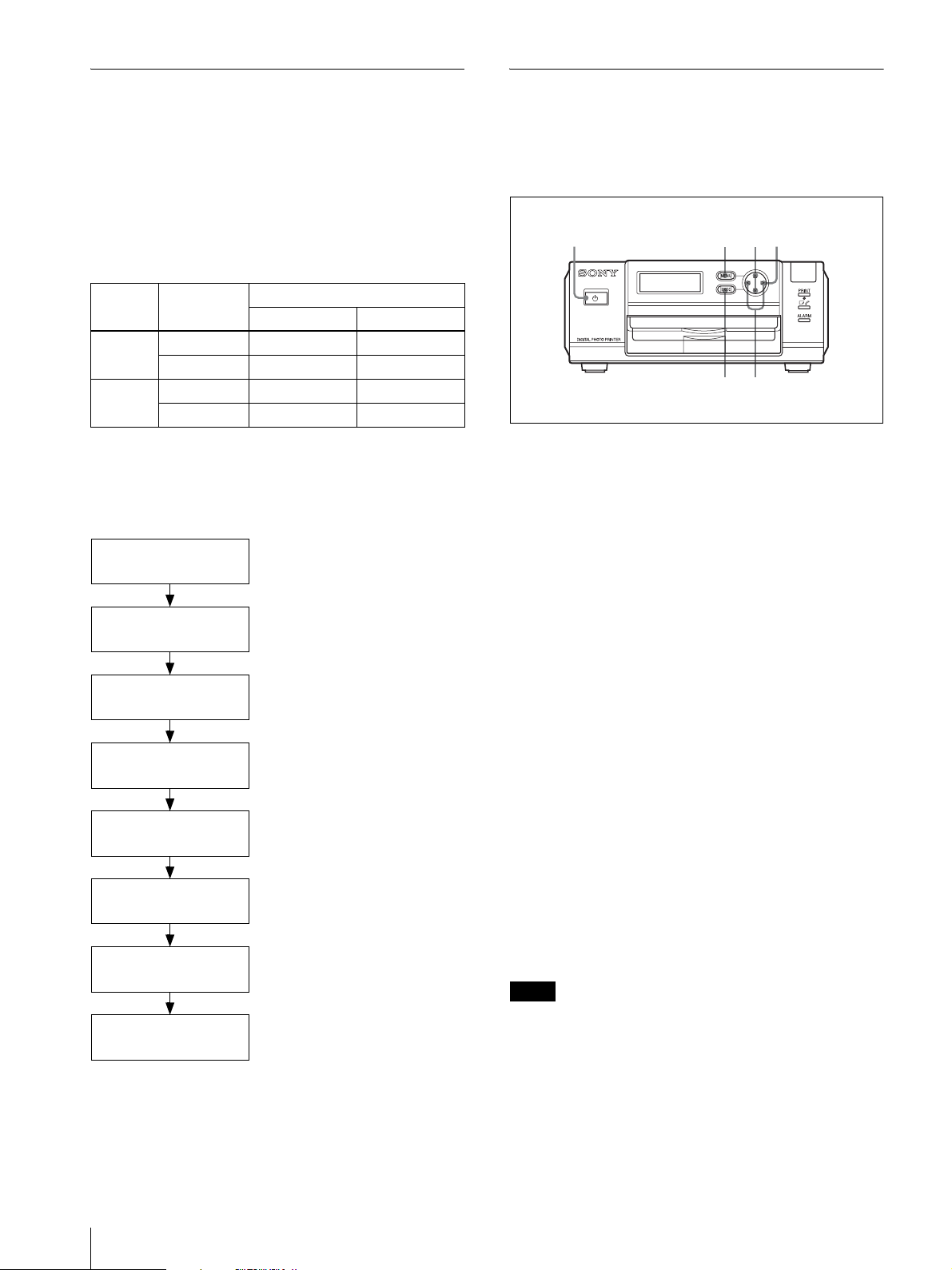
Printing Times
Adjusting the Print Position (PRINT
Print times differ depending on the print size and paper
size used.
Printing times
The following are examples of the approximate time it
takes from the moment the PRINT button is pressed on
the camera to the moment the printer receives the picture
data from the camera and prints one picture.
Print
paper
UPC-X34
series
UPC-X46
series
Resolution Print size
2 × 2 inches 45 × 35 mm
STD Approx. 83 sec Approx. 78 sec
HIGH Approx. 83 sec Approx. 78 sec
STD Approx. 120 sec Approx. 120 sec
HIGH Approx. 120 sec Approx. 120 sec
Display during printing process
When you print a picture, the operation that is being
processed appears on the printer operation display as
shown below.
Ready
OFFSET)
When using the UPC-X46 series, you can adjust the
print position in increments of 0.5 mm (1/32") so that the
printed picture is correctly positioned on the print paper.
1
234
65
1
Turn on the printer.
2
Press the MENU button.
3
Press v or V on the control button to display
“PRINT SETTING [>>]” on the operation display.
Receiving Image
BT [ ]
PROCESSING
PRINTING
[YELLOW]
PRINTING
[MAGENTA]
PRINTING
[CYAN]
PRINTING
[LAMI]
PRINTING
Receiving image data
Processing received data
Printing yellow
Printing magenta
Printing cyan
Laminating
Finishing print process
4
Press B on the control button.
The PRINT OFFSET screen appears.
5
Select an offset value by pressing b or B on the
control button.
6
Press the EXEC button.
The offset value selected in step 5 is confirmed, and
the PRINT SETTING screen reappears.
Print a picture and check that the picture is printed in the
correct position on the print paper. If further adjustment
is needed, repeat the above steps.
For details on printing a picture, see “Printing the Last
Picture Taken (From the Auto-Review Display)” on page
22.
To exit PRINT SETTING
Press the MENU button to return to the READY screen.
Note
When you have finished making adjustments, be sure to
press the MENU button to return to the READY screen.
If you do not return to the READY screen,
COMMUNICATION ERROR will appear on the LCD
of the camera the next time printing is performed, and
printing will fail.
50
Adjusting the Print Quality
Page 51
Setting the Bluetooth Functions
Bluetooth wireless technology
The bluetooth1) wireless technology allows
communication between various Bluetooth devices
without using cables. Devices which can use this
technology include computers, computers peripheral
devices, PDAs, and mobile phones. This
omnidirectional communication system enables
communication even if the Bluetooth device is in a bag
or if there are obstacles between the devices.
Also, the Bluetooth wireless technology has advanced
security functions, such as scrambled frequencies and
data encryption.
• When using the Bluetooth function, the distance
between the camera and the printer you intend to
connect must be within 10 m (33 feet) without
obstacles.
1) The trademark is owned by their proprietor and
used by Sony Corporation under license. The word Bluetooth
is printed in plain text throughout this document.
Passkey Authentication
A passkey is used to authenticate two Bluetooth devices
that have not previously been connected to each other.
This is to create a trusted relationship between them.
You need to enter the same characters or numbers
(passkey) for each device in the passkey-authentication
process. The UPX-C300 system uses a 4-digit number
as a passkey.
After the same passkey is set for the devices, the
authentication process for connection must be
performed.
Some Bluetooth devices require a new passkey entry
when the valid authentication period of the devices is
expired, the log file is deleted, or the security setting is
changed. Passkey entry may be required, depending on
the device, each time you intend to connect.
Once authentication of devices has been confirmed in
the UPX-C300 system, registration of each device
connection is stored in a log file. After that, you can
connect the devices without entering a passkey. If you
wish to change the passkey, first delete the log file from
the connected device, then register the devices again for
re-authentication.
This “Passkey” is also referred to as a “Bluetooth
passkey” etc. “PIN” is also used with the same meaning.
The “Basic Imaging Profile”
The “Basic Imaging Profile” (BIP) is the specifications
used when sending or receiving still images between
Bluetooth devices. The main features of the BIP enable
sending or receiving images, and use of the remote
shutter feature of a digital still camera.
To connect with your printer, the Bluetooth device must
be compatible with the “Image Push Feature” of the
“Basic Imaging Profile” (BIP).
Before using the Bluetooth device, check the Bluetooth
and BIP specifications of the device.
Bluetooth Address
A 12-digit code consisting of the numerics 0–9 and the
alphabetics (A–F) is assigned to each Bluetooth device.
This is a specific code for each Bluetooth device, and is
called a Bluetooth address or a Bluetooth ID. The
Bluetooth address is for distinguishing each device, so
the same code is not assigned to several devices, nor can
the code be changed.
Changing the passkey settings
You can change the passkey as required.
On the UPX-C300 and separately available UP-DX100
Digital Photo Printer, the same passkey has been set at
the factory. For communication security, it is
recommended to change the passkey for your system.
For details on changing settings, refer to the “Changing
the Passkey” on page 53.
Setting the Bluetooth Functions
51
Page 52
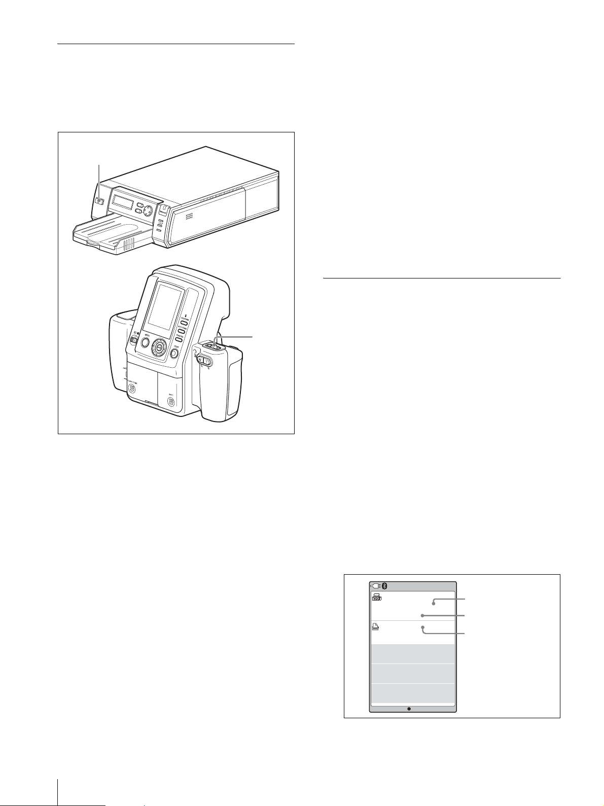
Bluetooth Connection
In the UPX-C300 system, the printer and the camera are
factory preset so that the camera automatically searches
for the printer for connection when both the printer and
the camera are turned on. Turn on the printer and the
camera according to the following procedures:
1
M
E
N
U
E
X
E
D
I
G
I
T
A
L
P
H
O
T
O
P
R
I
N
T
E
R
C
P
R
IN
T
PUSH OPEN
A
L
A
R
M
2
If the connection fails
The message “NOT DISCOVERED” is displayed on the
LCD of the camera, and the printer name and the
Bluetooth address remains displayed in gray. Even if the
connection fails, shooting and playback can be
performed on the camera.
If the connection fails, before retrying to connect, check
the following, then press the PRINT button. The
message “Reconnecting” is displayed and the
reconnection starts.
• The printer is turned on.
• The Bluetooth module of the camera and the printer is
set to ON.
• Between the camera and the printer, there is no
obstacle that disturbs data transmission.
For use with several printers connected, see “Operation
with Several Printers” on page 58 as well.
Checking the Bluetooth Connection Statuses of the Camera (PROPERTY)
1
Display the SETUP menu.
1
Turn on the printer.
Check that "Ready BT RSSI [----]" is displayed on
the operation display.
2
Set the on/standby switch of the camera to ? (on).
The camera starts searching for the printer, and
“DISCOVERING” is displayed on the LCD of the
camera. Upon establishment of connection between
the camera and the printer, the message changes to
“DISCOVERED,” and the name and the Bluetooth
address of the connected printer are displayed in
black.
To interrupt searching
While “DISCOVERING” is displayed on the LCD of
the camera, press the MENU button. “CANCELING” is
displayed, and the search is interrupted. If several
printers are connected, the search for the remaining
printers is also interrupted.
For details, see “Displaying the SETUP Menu” on
page 28.
2
Press v or V of the control button to select
Bluetooth.
3
Press the ENTER button.
The Bluetooth Menu display appears.
4
Press v or V of the control button to select
PROPERTY.
5
Press the ENTER button.
The Bluetooth information for the camera is
displayed.
You can scroll the printer list with v or V of the
control button.
Bluetooth
Sony
DKC-C300X
ADDRESS
:
00:13:E0:6F:4B:7F
PASS KEY: 1234
PRINTER LIST
1. Sony
UP-DX100
ADDRESS
00:A0:96:12:24:E1
2. . . . . . . . . .
ADDRESS
--:--:--:--:--:
3. . . . . . . . . .
ADDRESS
--:--:--:--:--:
OK
Bluetooth address of
the camera
Passkey
List of the connected
printers
--
--
52
Setting the Bluetooth Functions
When ENTER button is pressed, the display returns
to Bluetooth Menu.
Page 53
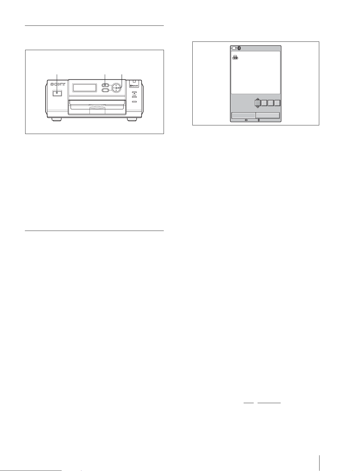
Confirming the Bluetooth Address of the Printer
1 2 3,4
MENU
1
DIGITAL PHOTO PRINTER
1
Turn on the printer.
2
Press the MENU button.
3
Press V of the control button to display "Bluetooth
SETTING[>>]."
4
Press B of the control button.
The Bluetooth address appears.
EXEC
PRINT
ALARM
5
Press the ENTER button.
The CHANGE PASSKEY display appears.
Bluetooth
CHANGE
OK
MOVE VALUE
PASSKEY
: 1234
1234
CANCEL
CURRENT KEY
NEW KEY :
6
Press b or B of the control button to select a digit
you wish to change.
7
Press v or V of the control button to set the value.
A value 0 to 9 can be used.
Repeat Steps 6 and 7 above to set a four-digit
passkey.
8
Press B of the control button to select OK.
To return to Ready, press the MENU button.
Changing the Passkey
The same passkey is set for all cameras and printers at
the factory. If the passkey needs to be changed, set a new
passkey, following the procedures below.
Once a new passkey is set, remove the printer
registration, and register it again. Then authentication of
the new passkey will be valid.
For details on removing a printer, see “Removing a
Printer” on page 58, and on registering a printer, see
“Adding/Registering a Printer” on page 56.
Changing the passkey of the camera
1
Display the SETUP menu.
For details, see “Displaying the SETUP Menu” on
page 28.
2
Press v or V of the control button to select
Bluetooth.
9
Press the ENTER button.
A new passkey has been set, and the display returns
to Bluetooth Menu.
To cancel changing the passkey setting
In Step 8 above, select CANCEL instead of OK, then
Press the ENTER button.
Changing the passkey of the printer
1
Turn on the printer.
“Ready BT RSSI [----]”appears on the operation
display.
2
Press the MENU button.
3
Press V of the control button to display “Bluetooth
SETTING [>>].”
4
Press B of the control button.
“Bluetooth ADDR” appears.
5
Press V of the control button to display “PASSKEY
INPUT [>>].”
3
Press the ENTER button.
The Bluetooth Menu display appears.
4
Press v or V of the control button to select
CHANGE PASSKEY.
6
Press B of the control button.
“PASSKEY INPUT <1>
Current digit to be set Passkey
[X:X:X:X]” appears.
||
Setting the Bluetooth Functions
53
Page 54

7
Press b or B of the control button to select a digit
of the passkey to be changed.
This <1> shows the leftmost digit, and <4> shows
the rightmost digit.
8
Press v or V of the control button to set the value
of the passkey.
A value from 0 to 9 can be used.
Repeat Steps 7 and 8 until the four-digit passkey is
set.
9
Press the EXEC button.
“PASSKEY INPUT Saving...” appears, and your
passkey setting is stored.
10
When the setting is completed, press the MENU
button.
Setting the Module Power
The Bluetooth Module Power must be set to ON to
connect the camera and the printer using the Bluetooth
function. If it is set to OFF, Bluetooth connection
between devices is not possible.
Changing the setting for Module Power of
the camera
1
Display the SETUP menu.
For details, see “Displaying the SETUP Menu” on
page 28.
2
Press v or V of the control button to select
Bluetooth.
Changing the setting for Module Power of
the printer
1
Turn on the printer.
2
Press the MENU button.
3
Press V of the control button to display "Bluetooth
SETTING[>>]."
4
Press B of the control button.
"Bluetooth ADDR" appears.
5
Press V of the control button to display "MODULE
POWER [>>]."
6
Press B of the control button.
7
Press b or B of the control button to select ON or
OFF.
8
Press the EXEC button.
“REBOOTING” is displayed. The printer restarts,
and the setting of the Module Power is changed.
If the Module Power setting of the printer is changed
from ON to OFF, the Bluetooth lamp goes off, and
"Ready BT RSSI [----]" is displayed on the operation
display of the printer. The camera treats this printer in
the same way as one whose printer name and Bluetooth
address are displayed in gray.
If the Module Power setting of the printer is changed
from OFF to ON, the Bluetooth lamp lights. To establish
connection between the camera and the printer, press the
PRINT button of the camera for reconnection.
3
Press the ENTER button.
The Bluetooth Menu display appears.
4
Press v or V of the control button to select
MODULE.
5
Press the ENTER button.
The BT MODULE POWER display appears.
6
Confirm that either ON or OFF is selected, then
Press the ENTER button.
The display returns to Bluetooth Menu.
To cancel changing the setting
In Step 6, press b of the control button. The display
returns to Bluetooth Menu.
When the module power for the camera is set to ON, the
(Bluetooth) icon appears at the top left of the LCD to
the right of the power indicator.
54
Setting the Bluetooth Functions
Page 55

Giving Your Printer a Device
Checking the Connection Record of
Number
When two or more printers are used in a system, it is
convenient that each printer have a device number (from
1 to 9).
1
Turn on the printer.
“Ready BT RSSI [----]” appears on the operation
display.
2
Press the MENU button.
3
Press V of the control button to display “Bluetooth
SETTING [>>].”
4
Press B of the control button.
5
Press V of the control button to display “MY
DEVICE NAME [>>].”
6
Press B of the control button.
“Sony UP-DX100 [NONE-9: EXEC]” appears.
7
Press v or V of the control button to set the device
number.
the Printer
1
Turn on the printer.
2
Press the MENU button.
3
Press V of the control button to display "Bluetooth
SETTING[>>]."
4
Press B of the control button.
“Bluetooth ADDR” appears.
5
Press V of the control button to display
“CONNECTION RECORD [>>].”
6
Press B of the control button.
The name and Bluetooth address of the devices
being connected with the printer are displayed.
To scroll the display to check the information on
other devices, press v or V of the control button.
To return to the “CONNECTION RECORD [>>]”
display, press the EXEC button.
To return to the Ready display, press the MENU button.
8
Press the EXEC button.
“DEVICE NAME Saving. . .” appears, and the
device number you have set is stored.
9
When the setting is completed, press the MENU
button.
Setting the Bluetooth Functions
55
Page 56
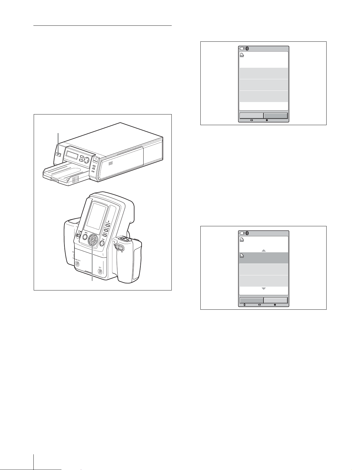
Adding/Registering a Printer
Up to three printers can be connected with the Bluetooth
function in the UPX-C300 system. Printers can be added
using the Setup menu of the camera.
Before adding a printer, the same passkey as that of the
camera must be assigned for the printer.
If "NO PRINTER" is indicated when the camera is
turned on, register the printer in the following manner:
For details on passkey setting, see “Changing the
Passkey” on page 53.
6
Press the ENTER button.
The ADD PRINTER display appears.
Bluetooth
ADD PRINTER
1. Sony
UP-DX100
ADDRESS
00:A0:96:12:24:E1
2. . . . . . . . . .
ADDRESS
--:--:--:--:--:
3. . . . . . . . . .
ADDRESS
--:--:--:--:--:
SELECT ENTER
--
--
CANCELSEARCH
1
M
E
N
U
E
X
E
D
I
G
I
T
A
L
P
H
O
T
O
P
R
I
N
T
E
R
1
Turn on the printer to be registered additionally.
C
P
R
I
N
T
A
L
A
R
M
Control button
PUSH OPEN
If one or two printers are still connectable, add
printer(s) as shown in the following steps.
If three printers are already connected, an
unnecessary printer must be deleted beforehand.
For details on how to remove a printer, see
“Removing a Printer” on page 58.
7
Press b of the control button to select SEARCH,
then press the ENTER button.
“Searching New Printers . . .” is displayed.
After searching is finished, the name and Bluetooth
address of the printer found are displayed in black.
The search for printers may take up to 60 seconds.
Bluetooth
Found Printer List
Sony
UP-DX100
ADDRESS
00:A0:96:12:24:E1
. . . . . . . . .
ADDRESS
--:--:--:--:--:
. . . . . . . . .
ADDRESS
--:--:--:--:--:
SELECT EXEC
SCROLL
--
--
CANCELADD
2
Display the SETUP menu.
For details, see “Displaying the SETUP Menu” on
page 28.
3
Press v or V of the control button to select
Bluetooth.
4
Press the ENTER button.
The Bluetooth Menu display appears.
5
Press v or V of the control button to select ADD
PRINTER.
56
Setting the Bluetooth Functions
8
Press v or V of the control button to select a printer
to be added.
9
Press b or B of the control button to select ADD,
then press the ENTER button.
Page 57
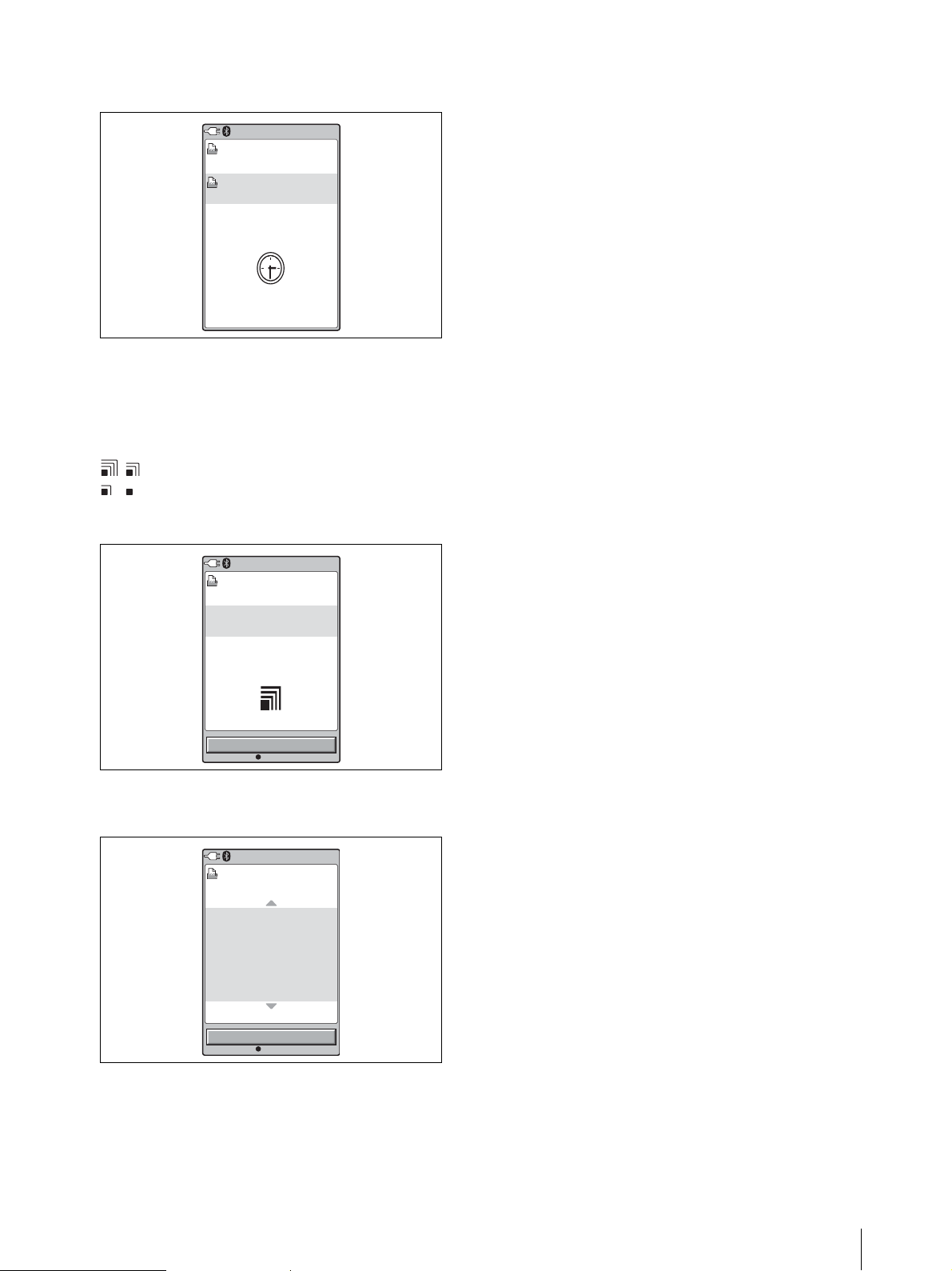
During the authentication process of the selected
printer, clock animation is displayed.
Bluetooth
Adding Printer
Sony
UP-DX100
ADDRESS
00:A0:96:12:24:E1
After the authentication process is finished, the
name of the printer to be added is displayed. At the
center of the display, an RSSI (Received Signal
Strength Indicator) symbol is displayed, which may
be used as a guide for adjusting locations of the
camera and the printer.
: The radio wave strength is good.
: The radio wave strength is a little weak, and
data transmission may require a long period of
time.
Bluetooth
Printer Added
1. Sony
UP-DX100
ADDRESS
00:A0:96:12:24:E1
Canceling addition/registration of the
printer
To cancel addition/registration of the printer, the
following two methods are available:
•In Step 7, while “Searching New Printers . . .” is
displayed, Press the ENTER button. Searching is
interrupted, and the display returns to Bluetooth
Menu.
•In Step 9, select CANCEL instead of ADD, then Press
the ENTER button. Addition/registration of the printer
is canceled.
If a printer cannot be added/registered
Printers cannot be added/registered in the following
cases:
• Three printers have been already connected.
t Delete an unnecessary printer.
• The passkey of the printer is different from that of the
camera.
t Set the same passkey as that of the camera.
If a message prompting printer update
appears
While using this system, a message prompting you to
update the printer’s firmware may appear on the camera
LCD. In such a case, contact your nearest Sony dealer.
OK
ENTER
10
Press the ENTER button.
The Printer List reappears.
Bluetooth
Printer List is
1. Sony
UP-DX100
ADDRESS
00:A0:96:12:24:E1
2. . . . . . . . . .
ADDRESS
--:--:--:--:--:
3. . . . . . . . . .
ADDRESS
--:--:--:--:--:
OK
ENTER
11
Press the ENTER button again.
The display returns to Bluetooth Menu.
--
--
Setting the Bluetooth Functions
57
Page 58

Removing a Printer
Operation with Several Printers
1
Display the SETUP menu.
For details, see “Displaying the SETUP Menu” on
page 28.
2
Press v or V of the control button to select
Bluetooth.
3
Press the ENTER button.
The Bluetooth Menu display appears.
4
Press v or V of the control button to select
REMOVE PRINTER.
The REMOVE PRINTER display appears.
5
Press v or V of the control button to select a printer
to be removed.
6
Press b or B of the control button to select
REMOVE.
7
Press the ENTER button.
The printer selected in Step 5 is removed, and its
printer name and Bluetooth address are deleted.
8
Press the ENTER button again.
The display returns to Bluetooth Menu.
To cancel removing the printer
In Step 6, select CANCEL instead of REMOVE, then
Press the ENTER button. Deletion of the printer is
canceled, and the display returns to Bluetooth Menu.
In a system using several printers, the basic operations
are the same as when one printer is used. If the camera
is turned on after a printer is turned on, the camera
automatically searches for registered printers. The
names and Bluetooth addresses of all printers with
which connection has been established are displayed in
black. Those of any printers with which connection has
failed are displayed in gray.
Printers to be used can be selected with the PRINTER
button. When a connected printer is selected, the print
conditions of the selected printer are displayed in white
on the LCD. If a printer that is not connected is selected,
an alarm will be displayed in yellow.
To establish a connection with a currently disconnected
printer, first check that the printer is turned on, and that
the Bluetooth lamp is lit. In addition, press the
PRINTER button on the camera, and make sure that the
name of the printer to be connected is displayed in
yellow. Then, press the PRINT button. “Reconnecting. .
.” is displayed, and the process of reconnection starts.
When reconnection has been established, in CAMERA
mode, the camera returns to the normal recording mode.
In PLAY or Auto Review mode, the Print Preview
display is displayed.
To start printing, press the PRINT button again.
Transmission of image data starts.
If printing is not required, press the MENU button to
terminate the Print Preview display.
58
Setting the Bluetooth Functions
Page 59

Maintaining System
Printer
Performance
To maintain system performance, be sure to read the
following.
Camera
Locations of use and storage
Using or storing the camera in any of the following
locations may result in a malfunction. Do not use or
store the camera in such locations.
• Extremely hot or cold locations (operating
temperature of 5 °C to 35 °C (41 °F to 95 °F)
• Locations subject to prolonged periods of direct
sunlight or near heating appliances
• Locations with excessive humidity or dust
• Locations exposed to rain
• Locations exposed to severe vibration
• Near sources of strong magnetism
• Near sources of strong electromagnetic waves such as
TV or radio transmitters
Heat dissipation
Do not cover the camera (such as with a cloth) Doing so
will increase the internal temperature and may result in
a malfunction.
Transportation
When transporting the camera, be sure to pack it in the
supplied carton and cushioning or equivalent packaging,
and make sure it is not subject to severe mechanical
shocks.
Precautions
• If you do not intend to use the printer for a long time,
set the printer to standby mode and disconnect the
power cord from the outlet.
• When transporting the printer, remove any
accessories. Failing to do so may result in a
malfunction.
Condensation
If the printer is moved from a location with low humidity
to a warm location or placed in a room with a heater that
causes steam and moisture to be generated, drops of
water may form inside the printer. This phenomenon is
referred to as condensation. If used in such a state, the
printer will not work properly and may even
malfunction. If there is a likelihood of condensation,
turn off the power and leave the printer to stand for a
while.
Cleaning
• Be sure to turn off the power and remove the power
plug prior to cleaning.
• Use a blower to remove dirt and dust from the surface
of the camera lens.
• Use a soft, dry cloth to gently wipe off dirt from the
exterior. If the exterior is extremely dirty, use a cloth
lightly moistened with a mild detergent solution to
wipe off the dirt and then use a dry cloth.
• Do not use volatile substances such as alcohol,
benzine, thinner, or insecticide because doing so may
damage the finish and erase the indications.
Taking test pictures
Be sure to take test pictures beforehand to ensure that
pictures can be taken normally.
Lens
Be careful not to bump into or press against the lens
while shooting.
Also, do not touch the lens surface.
Maintaining System Performance
59
Page 60

Specifications
Camera
General
Power supply Supplied from an AC power adaptor
(5.0 V DC) or from Sony NH-AA
Batteries (max. 2700 mAh)
Input current 1.65 A max. (using an AC power
adaptor)
Operating temperature
5° C to 35 °C (41 °F to 95 °F)
Storage temperature
–20 °C to +60 °C (–4 °F to +140 °F)
Operating humidity
20% to 80% (non condensation)
Dimensions (w/h/d)
222 × 194 × 102 mm
3
(8
/4 × 7 3/4 × 4 1/8 inches)
Mass Approx. 900 g (2 lb)
System
Camera type Digital still camera
Recording/playback system
Data compression/decompression system
Recording medium
Picture elements 1/2.5 inch 8M CCD solid-state
Recording resolution
Recording capacity
Number of shots (with Typ. 2000 mAh/Min. 1900 mAh
Delete method 1 picture delete, all picture delete
Frame digital
JPEG baseline system
Built-in 64 MB flash memory
picture element
3264 × 2448 pixels (HIGH)
1632 × 1224 pixels (STD)
approx. 30 or more pictures (High
resolution)
approx. 120 or more pictures
(Standard resolution)
AA nickel-hydride batteries)
Approx. 40 shots under the following
conditions:
– Temperature: 25°C
– Shooting conditions: 1) Adjust the
zoom to WIDE, TELE, and back to
WIDE after turning power on; 2)
take two shots using flash; 3) print
one image; 4) enter power save
mode after 10 minutes via AUTO
POWER SAVE.
Results will vary in lower
temperatures and other shooting
conditions.
White balance Program, One Push, 3000K to 7000K
(500K steps)
Shutter speed 1/2 to 1/1000 second
Photographic sensitivity
Equivalent to ISO 200
LCD monitor 3.0-inch cold polysilicone TFT color
LCD viewfinder
230,000 pixel
Lens f = 12.5 to 25 mm, 2 times (equivalent
to a 75 to 150-mm lens with a 35-
mm film camera), auto focus
F-value: F4.7 (at W) to F5.5 (at T)
Input/output connectors
DC IN 5.0V 5.0 V DC
RELEASE 3.5 mm ø (minijack)
Printer
Power supply 100 to 240 V AC, 50/60 Hz
Input current 1.1 A max.
Operating temperature
5°C to 35°C (41°F to 95°F)
Storage/transport temperature
–20 °C to +60 °C (–4 °F to +140 °F)
Operating humidity
20% to 80% (non condensation)
Maximum dimensions (w/h/d)
203 × 85 × 305 mm (8 × 3
1
12
/8 inches)
Mass Approx. 2.7 kg (5 lb 15 oz) (main unit
only)
Printing method Four-surface sequential sublimation
thermal transfer process
(yellow, magenta, cyan, laminate)
Print resolution
403 × 403 dpi
Thermal head 403 dots/inch
Print gradations
8 bits for yellow, magenta, cyan
Printing time UPC-X46 series: 100 sec./sheet
UPC-X34 series: 65 sec./sheet
Paper supply method
Autofeed from paper tray
Maximum capacity of paper tray
UPC-X46 series: 25 sheets
UPC-X34 series: 30 sheets
Paper eject method
Front ejection
Sheets are ejected in order on top of
paper tray
Printing capacity of ribbon cartridge
UPC-X46 series: 25 sheets
UPC-X34 series: 30 sheets
Inputs AC IN (power inlet)
Maximum print size
UPC-X46 series: 101.6 × 151.4 mm
(4 × 6
1
/8 inches) (no border)
3
/8 ×
60
Specifications
Page 61
UPC-X34 series: 70.1 × 95.3 mm
7
(2
/8 × 3 7/8 inches) (with border)
Print pixels UPC-X46 series: 1664 × 2440 dots
UPC-X34 series: 1112 × 1512 dots
10UPC-X46 Series Self-laminating Color Printing Pack
(250 sheets)
10UPC-X34 Series Self-laminating Color Printing Pack
(300 sheets)
Bluetooth specifications
Communication type (camera)
Bluetooth Specification, ver.2.0
Communication type (printer)
Bluetooth Specification, ver.1.1
Maximum transmission speed
About 723 Kbps
Output Bluetooth Specification, Power Class
2
Communication distance
About 10 m (3.3 feet) without
obstacles
Compatible Bluetooth profile
Basic Imaging Profile (Image Push
Feature)
Frequency band 2.4 GHz (2.400 GHz – 2.4835 GHz)
1) Maximum data transmission speed based on Bluetooth
Specification, Ver.2.0. This speed depends on the distance
between the devices, obstacles, radio wave conditions,
application software, or the OS.
2) This distance depends on the distance between the devices,
obstacles, radio wave conditions, application software, or the
OS.
3) This specification is in accordance with the intended use
between two Bluetooth devices. This is defined by the
Bluetooth Specification.
AC power adaptor
Power supply 100 to 240 V AC, 50/60 Hz
Input current 0.26 A
Output 5.0 V DC, 2.0 A in operating mode
Operating temperature
5°C to 35°C (41°F to 95°F)
Storage temperature
–20°C to +60°C (–4°F to +140°F)
Dimensions (W/H/D)
Approx. 69 × 26 × 50 mm (2-3/4 ×
1-1/16 × 2") (including
protrusions)
Weight Approx. 170 g (6.0 oz)
1)
2)
3)
Design and specifications are subject to change without
notice.
Note
• Always verify that the unit is operating properly
before use.
SONY WILL NOT BE LIABLE FOR DAMAGES
OF ANY KIND INCLUDING, BUT NOT
LIMITED TO, COMPENSATION OR
REIMBURSEMENT ON ACCOUNT OF
FAILURE TO PRINT CONTENT OF ANY TYPE
OR LOSS OF DATA DUE TO FAILURE OF THIS
UNIT OR ITS PRINTING MEDIA, ASSOCIATED
SOFTWARE, EXTERNAL STORAGE, OR
OTHER EXTERNAL DEVICE.
• SONY WILL NOT BE LIABLE FOR DAMAGES
OF ANY KIND INCLUDING, BUT NOT
LIMITED TO, COMPENSATION OR
REIMBURSEMENT ON ACCOUNT OF THE
LOSS OF PRESENT OR PROSPECTIVE
PROFITS DUE TO FAILURE OF THIS UNIT,
EITHER DURING THE WARRANTY PERIOD
OR AFTER EXPIRATION OF THE WARRANTY,
OR FOR ANY OTHER REASON
WHATSOEVER.
CAUTION
Danger of explosion if battery is incorrectly replaced.
Replace only with the same or equivalent type
recommended by the manufacturer. Dispose of used
batteries according to the manufacturer’s instructions.
Supplied accessories
Paper tray for the UPC-X46 series (1)
Paper tray for the UPC-X34 series (1)
Tray cover (1)
AC power adaptor UPA-AC05 (1)
Cleaning cassette (1)
Operating Instructions (2)
Quick Reference (1)
Optional accessories
UP-DX100 Digital Photo Printer
Specifications
61
Page 62
Troubleshooting
Check the following items prior to submitting the
equipment for repair. If the problem persists, contact
your nearest Sony dealer.
Camera
Symptom Cause/Solution
The camera does
not enter standby
mode even if the
on/standby switch
is set to
1 (standby).
The on/standby
switch of the
camera is set to
? (on), but the
camera and printer
are not connected.
The standby lamp
is lit orange or red,
and the camera
does not operate.
While Taking Pictures
Symptom Cause/Solution
A picture is not
taken when the
release button is
pressed.
• The camera’s internal processing is
taking a long time.
tWait a while. If the power still does
not enter standby mode, disconnect
the power cord or remove the
batteries.
• The power of the printer is not turned on.
tTurn the printer on, and then turn the
camera on.
• The Bluetooth module of the camera or
printer is turned off.
tTurn on both of the modules. (See
“Setting the Module Power” (on
page 54).)
• “NO PRINTER” appears.
tThe registration of the printer is
cancelled. Register the printer. (See
“Adding/Registering a Printer” (on
page 56).)
tThis is a problem with camera. Contact
your nearest Sony dealer.
• The mode switch is not set to .
tSet the mode switch to .
• Image data storage is in progress or the
flash is charging (the standby lamp is
rapidly flashing orange).
tWait until the standby lamp lights
orange.
• The memory is full (the standby lamp is
flashing orange).
tCheck the indication for the
remaining number of pictures that can
be taken. If it is zero, erase any
pictures that are not needed.
tSet AUTO ERASE to ON.
Symptom Cause/Solution
The flash does not
fire.
• Flash Mode is not set appropriately.
tSet FLASH MODE in the menu to
, or .
• The external flash is not lighting
properly.
tSet FLASH MODE in the menu to
, or .
• The batteries are dead.
tConnect the camera to an AC power
source, or replace the batteries with
new ones.
• The life of the flash is used up.
tContact your nearest Sony dealer.
Camera LCD
Symptom Cause/Solution
If the camera is
used in a cold
location, residual
images may
appear on the
LCD.
Black spots may
appear or red,
blue, green, or
other color spots
may remain on the
LCD.
A printer icon
appears in the
center of the LCD,
and the camera
does not operate.
The display image
freezes for a while
after data
transmission ends.
• This is a normal phenomenon associated
with LCDs.
tThis is not a malfunction.
• The printer is printing a picture.
tWait until printing finishes and
perform the operation again.
• Paper is being fed to the printer.
tThe display image will change when
the paper finishes feeding and printing
begins.
Printing
Symptom Cause/Solution
Pictures do not
print, even if the
PRINT button is
pressed.
• The camera is set to Shooting mode.
tPictures can only be printed from
auto-review display or Playback
mode.
• The print queue function is enabled.
tPrint using the print queue function,
or cancel this function. (See “Using
the Print Queue Function” on page
36)
62
Troubleshooting
Page 63
Picture Quality Printer
Symptom Cause/Solution
The picture is blurred. • The picture is out of focus.
tCheck the distance between the
lens and the subject, and make
sure the subject is within the
focus range.
• The camera was moved when the
release button was pressed.
tHold the camera correctly and
press the release button slowly.
• The shutter speed was too slow
because FLASH MODE is set to
or .
tSet the appropriate shooting
conditions. (See “Flash Mode
Setting Parameters” on page 8)
• The lens is dirty.
tClean the lens with a clean, soft,
dry cloth.
The picture is too dark. • Something (such as a finger) was
blocking the flash.
tHold the camera correctly and
make sure nothing is blocking the
flash.
• The subject was too far away.
tMake sure the subject is within
flash range when taking the
picture.
tCompensate the exposure.
• The subject was backlit.
tUse the flash.
The colors in a picture
taken indoors are not
correct.
Part of the picture is
missing.
• The lighting is affecting the colors.
tSet the white balance correctly.
(See “Adjusting the White
Balance” on page 34)
• Something (such as a finger) was
blocking the lens.
tHold the camera correctly and
make sure nothing is blocking the
lens.
Symptom Cause/Solution
Cannot turn on the
printer.
Cannot print. • The print paper and print cartridge do not
Cannot remove the
print cartridge.
White lines or
marks appear on
printed pictures.
The printer makes
short beeping
sounds and does
not perform an
operation.
The ALARM
lamp lights or
flashes and an
error message
appears.
• The power cord is not connected
properly.
tConnect the power cord to an AC
outlet properly.
match.
tUse a correct combination of print
paper and print cartridge designed for
the printer.
• “Waiting” is displayed on the operation
display because the internal temperature
of the printer is too high.
tIf the internal temperature of the
printer becomes too high, printing is
temporarily disabled. Wait until
printing resumes automatically.
• The print paper is jammed.
tRemove the jammed paper and try
again. (See “Removing Jammed
Paper” on page 64)
tThe print cartridge cannot be removed
while printing. Wait until printing is
finished. If the print cartridge still
cannot be removed, contact your
nearest Sony dealer.
• There may be dust on the thermal head.
tUse the supplied cleaning cassette to
clean the thermal head. (See
“Cleaning the Inside of the Printer” on
page 64)
• The roller inside the printer may be
marking the print paper.
tTry reducing the number of sheets in
the paper tray.
tThe printer makes short beeping sounds
when requested to perform an operation
that is not possible.
tFollow the on-screen instructions.
Troubleshooting
63
Page 64
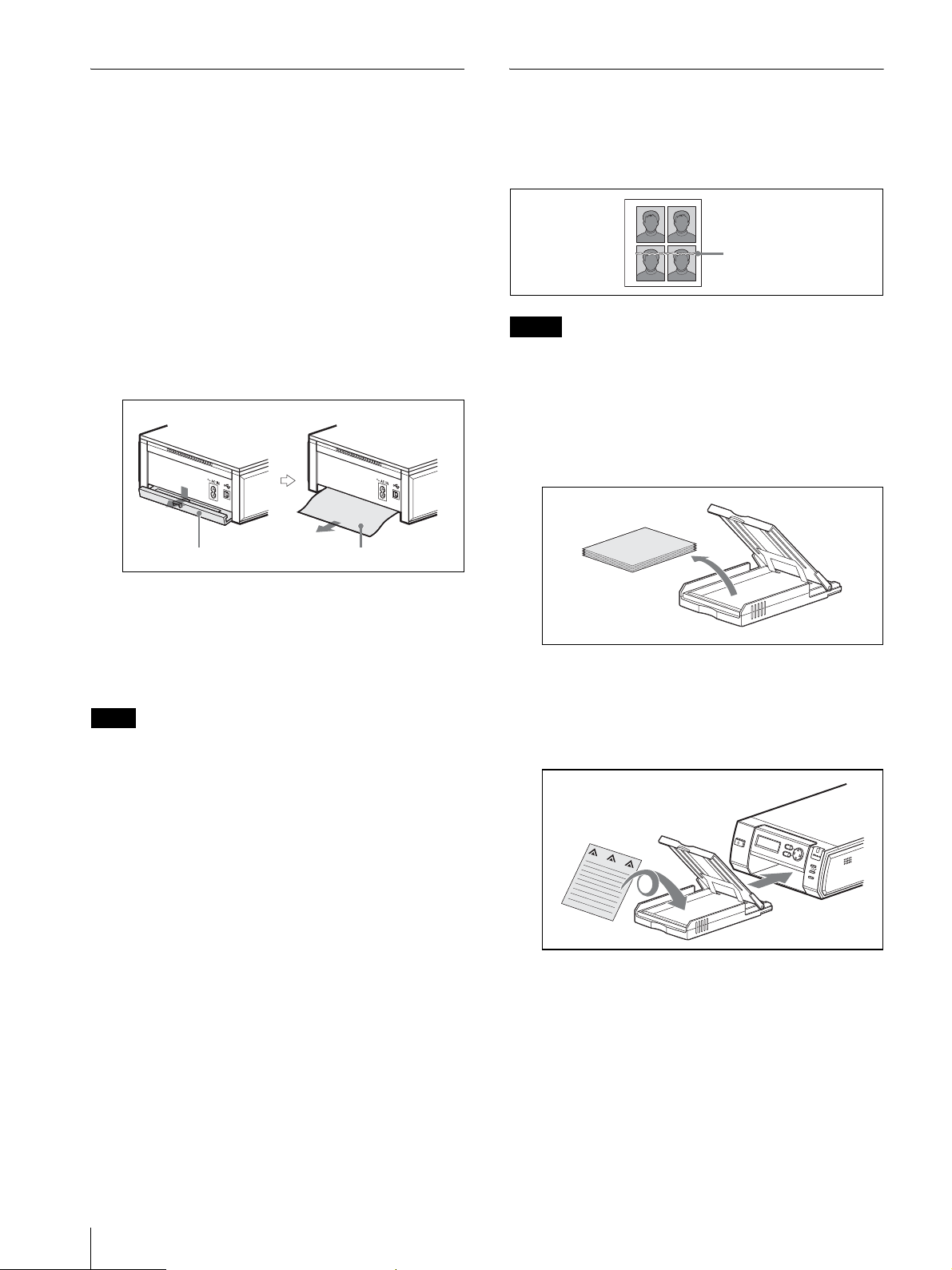
Removing Jammed Paper
Cleaning the Inside of the Printer
If a paper jam occurs while printing is in progress, the
ALARM lamp lights, an error message appears, and
printing stops.
Perform the following steps to remove the jammed
paper.
1
Press the 1 button on the printer to switch to
standby mode.
2
Remove the paper tray, and then remove any
jammed paper.
3
Remove the paper jam cover on the rear panel, and
check that there is no jammed paper. If there is any
jammed paper, remove it.
Paper jam cover Jammed paper
If white lines or dots appear on printed pictures, clean
the inside of the printer using the supplied cleaning
cassette and the protective sheet included with the
printing pack.
White lines
Notes
• Only perform cleaning if there are white lines or dots
on the printed pictures.
• When the printer is printing pictures normally,
cleaning will not improve print quality.
1
Remove the paper tray from the printer, and then
remove the paper from the tray.
4
Reattach the paper jam cover.
5
Insert the paper tray.
6
Turn on the printer.
Note
If you are unable to remove the jammed paper, contact
your nearest Sony dealer.
2
Place the protective sheet in the tray so that the
unprinted side is facing up, make sure the arrows on
the bottom of the tray and arrows on the printed side
of the sheet are pointing in the same direction, and
then insert the paper tray into the printer.
MENU
D
IG
ITAL PHO
EXEC
TO
PRIN
TER
N
E
P
P
O
R
IN
H
S
T
U
P
A
L
A
R
M
64
Troubleshooting
Page 65
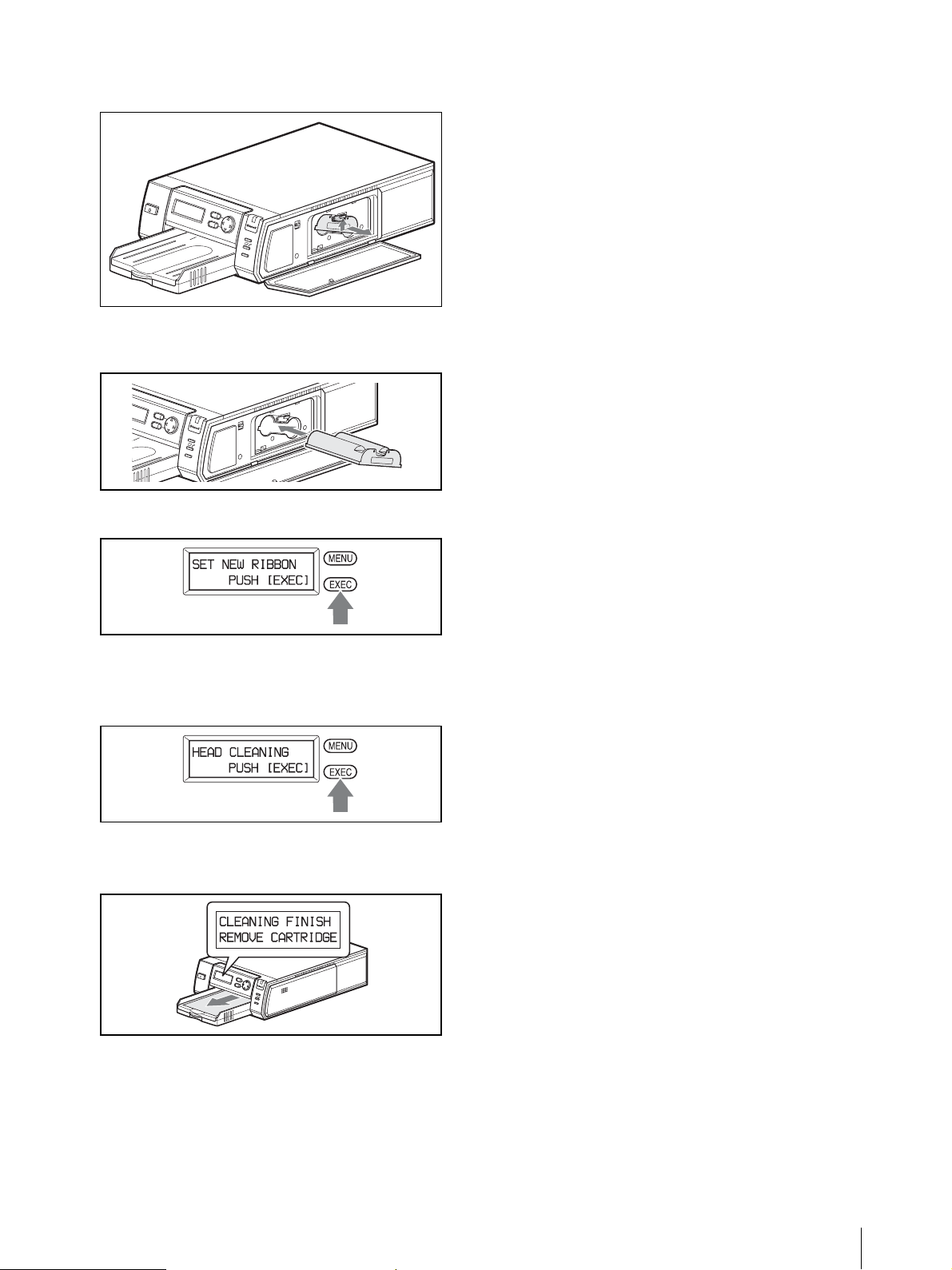
3
Open the print cartridge cover and remove the print
cartridge.
M
E
N
U
E
X
E
D
I
G
I
T
A
L
P
H
O
T
O
P
R
I
N
T
E
R
4
Insert the supplied cleaning cassette and close the
C
P
R
I
N
T
A
L
A
R
M
print cartridge cover.
M
E
N
U
E
X
E
C
P
R
I
N
T
A
L
A
R
M
5
Press the EXEC button.
A buzzer sounds and “HEAD CLEANING/PUSH
[EXEC]” appears.
6
Press the EXEC button again.
The cleaning cassette and protective sheet clean the
inside of the printer. After cleaning is finished, the
protective sheet is automatically ejected.
M
E
N
U
E
X
E
C
DIGITAL PHOTO
PRINTER
7
Remove the cleaning cassette from the printer, and
N
E
P
P
O
R
I
H
N
S
T
U
P
A
L
A
R
M
reinsert the print cartridge and paper tray.
Troubleshooting
65
Page 66
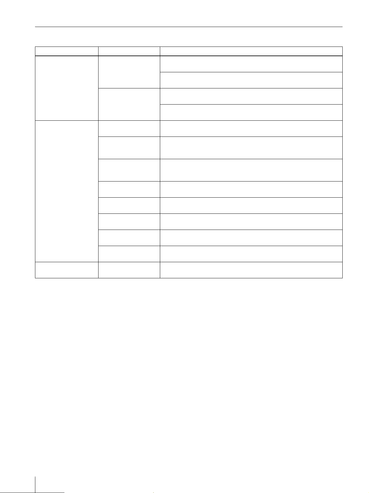
Error Messages
Camera Printer Cause/Solution
SET MEDIA SET NEW RIBBON
PUSH [EXEC]
SET PAPER
PUSH [EXEC]
CHECK PRINTER MEDIA MISMATCH
TRANSMISSION
FAI LE D!
PUSH [EXEC]
PAPER JAMM I N G
REMOVE PRINTS
REMOVE PRINTS
PUSH [EXEC]
BLUETOOTH ERROR
SERVICE CALL
PRINTER ERROR
PLEASE RETRY
PRINTER ERROR
SERVICE CALL
— • The menu is displayed in the operation display on the printer.
— • The printer is not connected correctly.
— • Print data failed to transmit.
After performing the actions described above, press the MENU button to clear the error message on the camera.
• The print cartridge is not installed properly.
tInstall the print cartridge properly, and press the EXEC button.
• The print cartridge has run out.
tReplace the print cartridge, and press the EXEC button.
• The paper tray is not installed.
tInstall the paper tray, and press the EXEC button.
• The print paper has run out.
tInsert print paper, and press the EXEC button.
• The print paper and print cartridge do not match.
tInsert the correct print paper and press the EXEC button.
• There is a print paper jam.
tRemove the jammed paper, and try printing again. (See “Removing Jammed
Paper” on page 64)
• Print paper remains in the ejection slot.
tRemove the paper tray, remove the print paper, and then press the EXEC
button.
• There is a problem with the Bluetooth function.
tContact your nearest Sony dealer.
• An error has occurred with the printer.
tTry printing again.
• There is a problem with the printer.
tContact your nearest Sony dealer.
tEnd the menu operation, and display the READY screen.
tRestart the camera and printer, and then try again.
tRestart the camera and printer, and then try the operation again.
66
Troubleshooting
Page 67
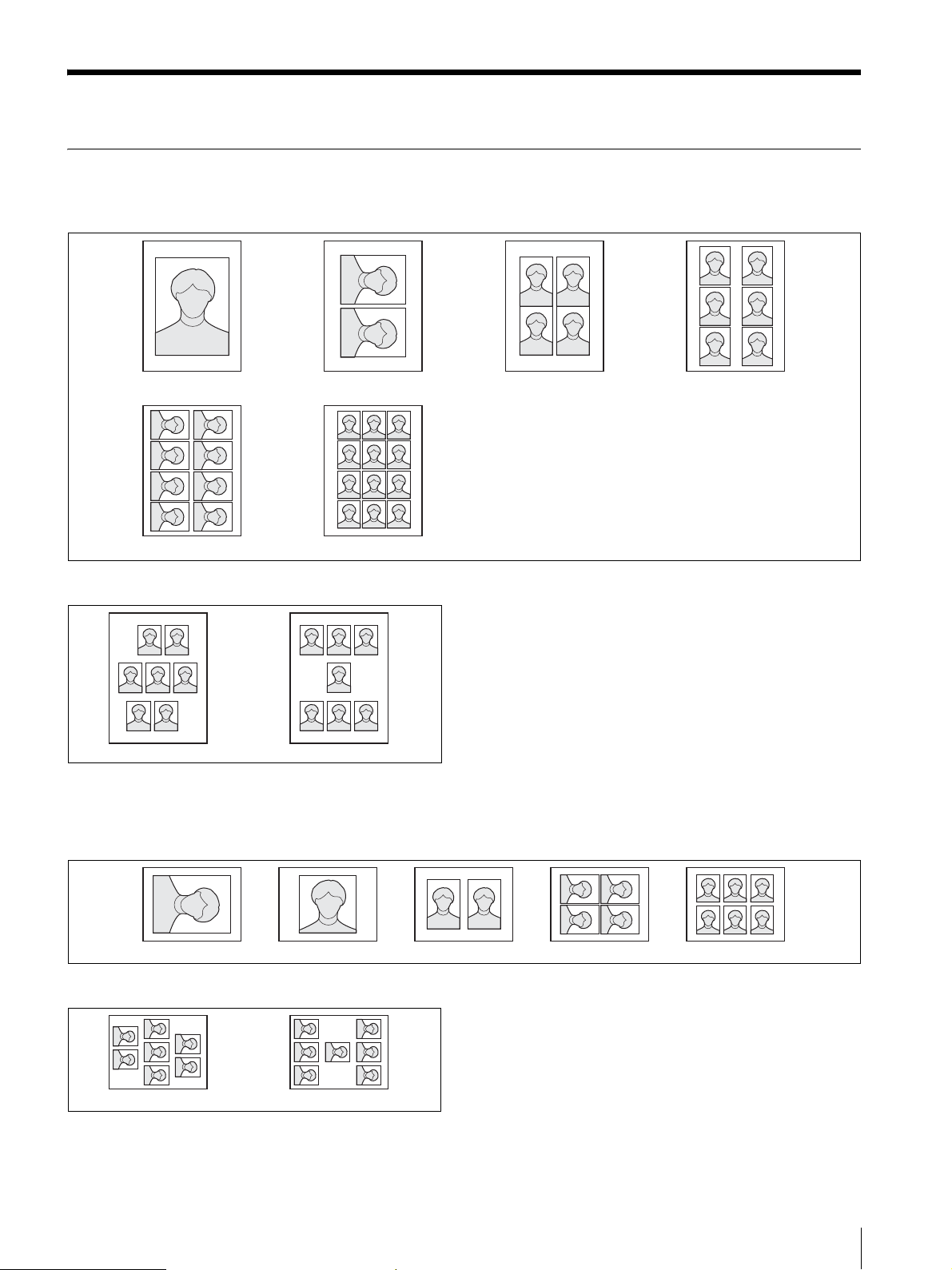
Apendix
Print Layouts
Layout examples when using UPC-X46 series print paper
90 × 65 mm 80 × 60 mm 60 × 40 mm 47 × 37 mm
45 × 35 mm 34 × 28 mm
Guide print
Guide Print-DLGmGuide Print-RGB
These guides are useful when adjusting the image quality of the printer.
Layout examples when using UPC-X34 series print paper
60 × 40 mm 45 × 35 mm 34 × 28 mm90 × 65 mm 2 × 2 inch
Guide print
Guide Print-DLGmGuide Print-RGB
These guides are useful when adjusting the image quality of the printer.
Apendix
67
Page 68

Index
A
AC power
Camera 14
Printer 19
AC power adaptor 14
ALARM lamp 12
APERTURE 29
Aperture 33
AUTO ERASE 29
Auto erase mode 32
AUTO FRAME (automatic position
matching) button 10
Auto power save 40
Autofocus function 9, 22
Auto-review 21, 22
B
Basic Imaging Profile (BIP) 51
Battery compartment lid 11
Battery power indicator 15
BIP 51
Black & white guide print 48
Adjusting balance of three
colors 48
Black & white prints 24
Bluetooth 31
Bluetooth address 51
Confirming 53
Bluetooth connection 52
Checking 52
If the connection fails 52
Bluetooth functions 51
Bluetooth lamp 12
Bluetooth SETTING 31
Built-in flash
Changing the flash mode 33
No flash mode 7
C
CAMERA SOUND 31
Capture menu 27, 29
Capture mode 29
Cartridge release lever 12
Cleaning 59, 64
COLOR ADJUST 31
Color tone adjustment (printer) 48
Complementary colors 48
Connection Record 55
Checking 55
Connections
AC power 14
Control button 12
COPY PRINT 24, 31
Country code 37
D
Data transmission 23
Cancel 23
DC IN 11
DELETE 30
DELETE ALL 30
Deleting pictures 25
All pictures 26
Canceling 26
Exiting picture deletion 26
Individual pictures 26
Pictures in playback 25
Device number 55
Die-cut print 40
Display during printing 50
Display language 42
E
ENTER button 11
Error messages 66
EXEC (Execute) button 12
Exposure
Compensating 35
Compensation function
(Capture mode) 22
Manual exposure 7
Exposure compensation value 21
Exposure control and Fash Mode 33
External connector cover 11
F
FIRMWARE VERSION 31, 43
Flash 9
FLASH jack 11
FLASH MODE 29
Flash mode (exposure control and
flash mode)
Changing the mode 33
Modes and environment
examples 7
G
Guide print 67
Black & white prints 48
Guide Print-DLGm 48
Guide Print-RGB 47
I
ID photo frame 37
Setting up a frame for display
during printing 37
Image Push Feature 51
Image resolution 20, 32
L
LANGUAGE 31
LCD screen (camera)
During layout preview 23
During playback 25
While taking pictures 21
LCD screen (printer)
During printing 50
Lens 9
Locking menus 43
M
Memory
Deleting pictures 21
Menu (camera)
Capture mode 29
Functions of menu items 29
Locking 43
Playback mode 30
SETUP 30
MENU button 11
Mode switch 11
Module Power
Changing the setting for Module
Power of the camera 54
Changing the setting for Module
Power of the printer 54
N
Nine-picture multiple display 25
Number of pictures (total number) 25
Number of pictures that can be taken
32, 62
O
On/standby switch 10
OnePush 34
Operation display (camera)
During layout preview 23
During playback 25
While taking pictures 21
Operation display (printer) 12
Operation sounds (camera) 41
P
Paper jams 64
Paper jam cover 13
68
Index
Page 69

Paper tray slot 12
Parameters
B parameter 45
D parameter 46
G parameter 45
Gm parameter 46
L parameter 46
R parameter 45
Passkey 31, 51, 53, 56
Changing the passkey of the
camera 53
Changing the passkey of the
printer 53
Changing the settings 51
Passkey authentication 51
Picture information 35
Playback
LCD screen 25
Playback menu 27, 30
Playback mode 30
Power 20
Preparations
Camera 14
Printer 16
Print cartridge cover 12
Print cartridge slot 12
Print cartridges
Loading 18
PRINT lamp (printer) 12
Print layout
List 67
PRINT OFFSET 50
Print packs 16
Print paper 17
Print preview screen 23
Print quality adjustment 24, 44
Black & white prints 24
Parameters 45
Print queue flag 25
Print size 23, 32
Print size (print layout)
List 67
PRINT SIZE LIST 30
Print time 60
Printer 56
Adding/Registering 56
Canceling addition/registration
57
If a printer cannot be added/
registered 57
Operation with Several Printers
58
Preparing 16
Removing 58
To cancel removing 58
PRINTER button 10
Printing 22
Printing pictures stored in the
camera’s built-in
memory 24
Printing the last picture taken 22
Reprinting pictures from the
printer’s memory 24
Printing time 50
PROPERTY 30, 52
Q
Quick Review mode 58
R
Recording capacity 60
Release button 9
Removing jammed paper 64
Reprinting (from the printer’s
memory) 24
Setting the number of sheets 24
Reset default settings 42
RESET SETTING 31
RESOLUTION 29
Resolution 21, 25
RGB parameter adjustment 47
RSSI (Received Signal Strength
Indicator) 57
S
Settings 27
SETUP 29, 30
SETUP menu 28, 30
Shooting condition 8, 20
Factory settings 20
Shooting environments 7
SHUTTER 29
Shutter speed 34
Sound (camera) 41
Standby lamp (camera) 10
Standby mode 20
Supplied accessories 14
System configuration 5
T
Taking pictures 21
LCD screen 21
Total number of pictures in
memory 25
TOTAL PRINTS 31
Tray cover 18
Tripod 16
Tripod screw hole 9
Troubleshooting 62
U
USB connector 13
V
Viewing captured pictures 24
W
WHITE BALANCE 29
White balance
Adjusting 34
Capturing 34
Z
Zoom
Zoom lever 11
Index
69
Page 70

Sony Corporation
 Loading...