

SONY DK1830SI Service Manual

DK1910SI & DK1930SI
DK1810SI & DK1830SI
& DK1840SI
service manual

Catalog
Chapter One About Maintenance
1.1 Safety precautions
1.1.1 Power supply
1.1.2 Precautions for antistatic
1.1.3 Precautions for laser head
1.1.4 About placement position
1.2 Maintenance method
1.2.1 Visualized method
1.2.2 Electric resistance method
1.2.3 Voltage method
1.2.4 Current method
1.2.5 Cutting method
1.2.6 Element substitution method
1.2.7 Comparison method
1.3 Required device for maintenance
1
1
1
1
1
2
2
2
2
2
2
2
3
3
3
Chapter Two Functions and Operation Instructions
2.1 Features
2.2 Controls and functions
2.2.1 Front Panel controls
2.2.2 Rear panel connections
2.2.3 VFD display general view
2.2.4 Remote control general view
2.3 FUNCTION SETTINGS
2.3.1 Function selection and change
2.3.2 Language settings
2.3.3 Image settings menu
2.3.4 Sound settings menu
2.3.5 Playback settings
2.3.6 Karaoke settings menu
4
4
5
5
5
6
6
8
8
8
8
9
10
10

2.3.7 Preference settings
11
2.3.8 Parental Control
2.3.9 Initial setup menu
2.3.10 reset to defaults
2.3.11 Exit settings menu
2.3.12 Channel delay set-up
2.4 Technical characteristics
Chapter Three Principle and Servicing
Section One Principle of the Player
3.1.1 Function and features
3.1.2 Block diagram of the player
3.1.3 Introduction to IC used in this player
Section Two Unit Circuit Principle
3.2.1 Introduction to laser head
3.2.2 Servo circuit
11
11
11
11
11
13
15
15
15
15
17
18
18
20
3.2.3 Main axis braking control circuit
3.2.4 Disc identification circuit
3.2.5 Disc in/out circuit
3.2.6 Reset circuit
3.2.7 Mute circuit
3.2.8 Video circuit
3.2.9 Audio power amplifying circuit block diagram
3.2.10 Input/output circuit
3.2.11 Control panel components
3.2.12 Power supply circuit
Section Three Servicing Cases
3.3.1 Servicing cases
3.3.2 Troubleshooting flow chart
Section Four Waveform diagram
Section Five Function Introduction to IC
23
24
25
26
27
28
29
29
31
32
35
35
38
44
49
3.5.1 function introduction to MT1389HD
3.5.2 function introduction to AT24C02
3.5.3 function introduction to 74HCU04
3.5.4 function introduction to Lm1117
49
65
66
66

3.5.5 function introduction to 29LV160BE
67
3.5.6 function introduction to HY57V641620HGT -7
3.5.7 function introduction to D5954
3.5.8 function introduction to 4558
3.5.9 function introduction to SN74LVC
3.5.10 function introduction to 74HCT125
3.5.11 function introduction to Cd4052
3.5.12 function introduction to SAA6588
3.5.13 function introduction to 5340
3.5.14 function introduction to TLV272
3.5.15 function introduction to Lm4880
3.5.16 function introduction to TAS5508PAG
3.5.17 function introduction to TAS5112DFD
3.5.18 function introduction to Ad7312
3.5.19 function introduction to VIPer22ADIP
3.5.20 function introduction to Hs817
68
69
70
71
71
72
73
75
76
77
78
80
83
85
85
3.5.21 function introduction to TL431A
3.5.22 function introduction to KA1M0880BTU
Chapter Four Disassembly and Assembly Process
Chapter Cinque PCB board & Circuit diagram
Section One PCB board
Section Two circuit diagram
Chapter six BOM List
86
86
88
89
89
98
104

Chapter One About Maintenance
1.1 Safety precautions
1.1.1 Power supply
When maintenance personnel are repairing DVD players, he should pay special attention to the
power board with 220V AC and 330V DC which will cause hurt and damage to persons!
1.1.2 Precautions for antistatic
Movement and friction will both bring static electricity which causes serious damages to integrated
IC. Though static charge is little, when a limited quantity of electric charge is added to large-
scaleintegrated IC, as the capacitance is very small in the meantime, now the integrated IC is very much
easy to be struck through by static electricity or the performance will decrease. Thus static electricity
prevention is of extraordinary importance. The following are several measures to prevent static
electricity:
1. Use a piece of electric conduction metal with the length of about 2 metres to insert into the earth,
and Fetch the lead wire from the top of the surplus metal and connect to the required static electricity
device. The length and depth of the metal embedded under the earth should be determined according to
the wettability of the local soil. For humid places, it may be shorter, and longer and deeper for dry places.
If possible, it can be distributed and layed in terms of “#” shape.
2. On operating table-board, the antistatic table cushion should be covered and grounded.
3. All devices and equipments should be placed on the antistatic table cushion and grounded.
4. Maintenance personnel should wear antistatic wrist ring which should be grounded.
5. Places around the operating position should also be covered with electric conduction cushion or
Painted with antistatic paint.
1.1.3 Precautions for laser head
1. Do not stare at laser head directly, for laser emission will occur when laser head is working, which
will Hurt your eyes!
2. Do not use wiping water or alcohol to clean laser head, and you may use cotton swab.
- 1 -

1.1.4 About placement position
1. Never place DVD player in positions with high temperature and humidity.
2. Avoid placing near high magnetic fields, such as loudspeaker or magnet.
3. Positions for placement should be stable and secure.
1.2 Maintenance method
1.2.1 Visualized method
Directly view whether abnormalities of collision, lack of element, joint welding, shedding welding,
rosin joint, copper foil turning up, lead wire disconnection and elements burning up among pins of
elements appear. Check power supply of the machine and then use hands to touch the casing of part of
elements and check whether they are hot to judge the trouble spot. You should pay more attention when
using this method to check in high voltage parts.
1.2.2 Electric resistance method
Set the multimeter in resistance position and test whether the numerical value of resistance of each
point in the circuit has difference from the normal value to judge the trouble spot. But in the circuit the
tested numerical value of resistance is not accurate, and the tested numerical value of integrated IC's
pins can only be used for reference, so the elements should be broken down for test.
1.2.3 Voltage method
Voltage method is relatively convenient, quick and accurate. Set the multimeter in voltage position
and test power supply voltage of the player and voltage of a certain point to judge the trouble spot
according to the tested voltage variation.
1.2.4 Current method
Set the multimeter in current position and test current of the player of a certain point to judge the
trouble spot. But when testing in current method, the multimeter should be series connected in the
circuit, which makes this method too trivial and troublesome, so it is less frequently used in reality.
1.2.5 Cutting method
Cutting method should be combined with electric resistance method and voltage method to use.
This method is mainly used in phenomena of short circuit and current leakage of the circuit. When
cutting the input terminal voltage of a certain level, if voltage of the player rises again, it means that the
trouble lies in this level.
- 2 -

1.2.6 Element substitution method
When some elements cannot be judged good or bad, substitution method may de adopted directly.
1.2.7 Comparison method
A same good PC board is usually used to test the correct voltage and waveform. Compared these
data with those tested through fault PC board, the cause of troubles may be found.
Through the above maintenance method, theoretical knowledge and maintenance experience, all
difficulties and troubles will be readily solved.
1.3 Required device for maintenance
Digital oscillograph ( 100MHE)
TV set
SMD rework station
Multimeter
Soldering iron
Pointed-month pincers
Cutting nippers
Forceps
Electric screw driver
Terminals connecting cord
Headphone
Microphone
- 3 -

Chapter Two
Functions and Operation Instructions
2.1 Features
Formats:
#Digital video playback of DVD-Video, Super VCD and VCD formats
#MPEG-4 compatibility: playback of DivX 3.11, DivX 4, DivX 5, DivX Pro and XviD formats
#Playback of music discs in DVD-Audio format
#Playback of musical compositions in CD-DA and HDCD formats
#Playback of compressed musical files in Mp3 and CD+G formats
#Playback of Karaoke-discs in DVD, VCD and CD+G formats
#Playback of photo albums, recorded in Kodak Picture CD and JPEG digital formats
Audio:
#192 kHz/12 bit audio D/A converter
#Coaxial and optical audio outputs, providing digital sound playback in Dolby Digital/DTS/LPC formats
#Coaxial and optical audio inputs, providing connection of external digital signal sources
#Stereophonic audio output for connection to TV and amplifier
#Integrated digital multi-channel sound decoders, providing playback of Dolby Digital and DTS audio
tracks
#Integrated Dolby Pro Logic ll decoder, providing transformation of stereophonic signal to multi-channel
one
#Microphone input providing karaoke functions
#Headphones output
Video:
#108kHz/12 bit video D/A converter
#Progressive scan(Y Pb Pr)video signal output, securing high resolution and absence of image flicker
#Composite and component(Y Cb Cr), S-Video and RGB/SCART video outputs, providing advanced
switching capabilities
#NTSC/PAL transcoder
#Support of many camera angels, dubbed languages and subtitles
#Sharpness, Gamma, Brightness, Contrast, Hue and Saturation adjustment.
Miscellaneous:
#Support of CD-R/CD-RW, DVD-R/DVD-RW, DVD+R/DVD+RW
#FM/AM tuner with RDS support
#USB port, providing playback of files of supported formats from external flash-memory devices
#KARAOKE+, providing extended karaoke features
#Easy to use on-screen menu in Russian
#Support of Russian file names, Id3 tags and CD-text
#”Memory” function which can load the last disc position on stop
- 4 -
#”Capture” function, auto loading selected bookmarked image as the wallpaper
#Q-Play function that will bring you to the main movie title and skip unskippable commercials
#Virtual control panel function makes your control of the device much easier when playing the movie
#Browser function displays information about playback modes
#Auto protection of TV screen
#Child lock, parental control(protection against playing undesirable discs)
2.2 Controls and functions
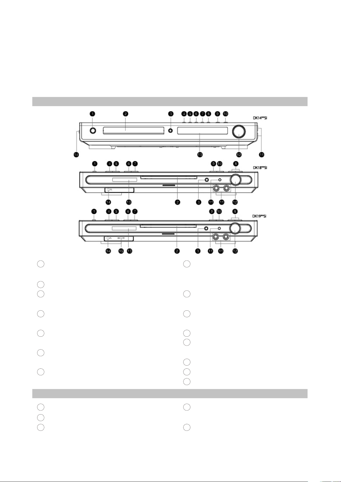
2.2.1 Front panel controls
1
STANDBY/POWER button
Press to switch the device on/into standby
Disc tray
2
3
Open/close button
Press to open/close the disc tray
PREV button
4
Press to playback from the previous bookmark
NEXT button
5
Press to playback from the next bookmark
PEW button
6
Press to fast reverse/radio station tuning
7
Forward button
Press to fast forward/radio station tuning
2.2.2 Rear panel connections
1
AM Antenna input
2
FM Antenna input
3
Left front speaker input(output from the build-in
8
SOURCE button
Press to switch between DVD-receiver/Audio
input/Tuner/Digital audio input
9
PLAY/PAUSE button
Press to playback/pause
10
STOP button
Press to stop the playback
11
Microphone input
12
VOLUME adjuster
Press to adjust volume
13
VFD display window
14
Headphones input
15
USB port
4
Right front speaker input(output from the build-
i n amplifier)
5
Center speaker input(output from the build-in
amplifier)
amplifier
- 5 -
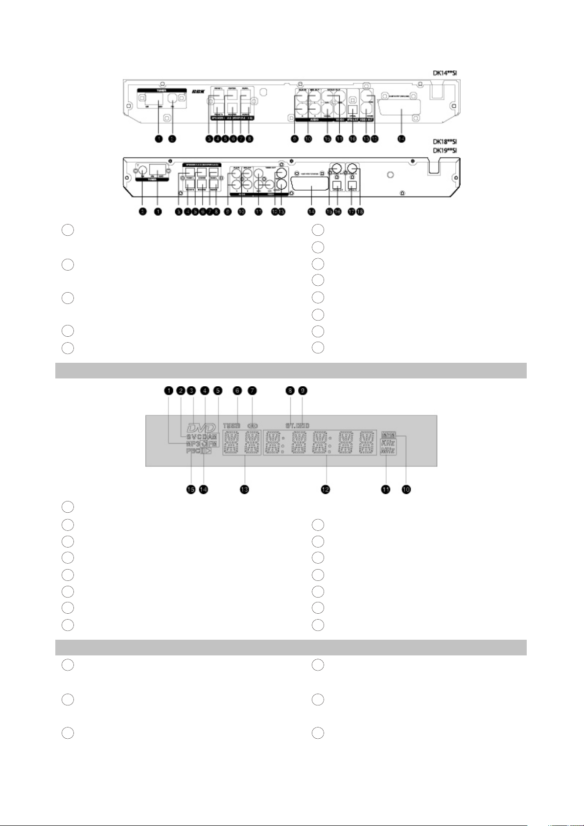
6
Subwoofer input(output from the build-in
amplifier)
Left Surround speaker input(output from the
7
build-in amplifier)
Right Surround speaker input(output from the
8
build-in amplifier)
9
Audio input
10
Stereophonic audio output
2.2.3 VFD display general view
1
MP3-disc
11
Component video output Y Cb(Pb)Cr(Pr)
12
Composite video output
13
S-Video output
14
SCART-type V connector
15
Coaxial digital audio output
16
Optical digital audio output
17
Optical digital audio input
18
Coaxial digital audio input
CD-, VCD- or SVCD-disc
2
DVD-disc
3
4
Repeat
5
AM/FM
6
Radio tuning mode
7
Tuner mode
8
Stereo
2.2.4 Remote control general view
1
EJECT button
Press to open/close the disc tray
DVD button
2
Press to switch to DVD mode
3
AUDIO button
Press to display the disc information
- 6 -
9
Dolby Digital
10
Programmed radio station
11
Friquency
12
Playback time
13
Chapters or tracks
14
Playback or pause
15
PBC
4
DISP button
Press to display the disc information
LANG button
5
Press to change the language
6
SLEEP button
Press to turn the sleep mode on
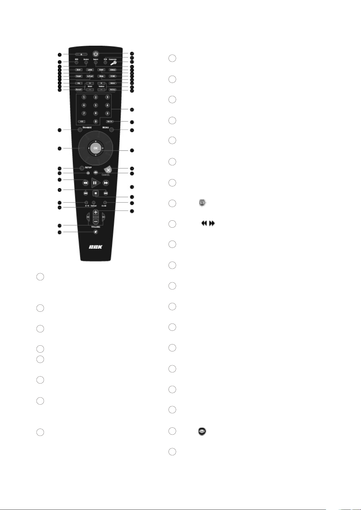
7
Q-PLAY button
Press to turn the Q-Play mode on.
EQ button
8
Press to adjust the equalizer
9
BASS +/- button
Press to adjust subwoofer
10
BOOST button
Press to bass boosting
11
BROWSER button
Press to turn on/off the browser function
12
JOG DIAL wheel
Functions are set manually. Default function: ZOOM
13
SETUP button
Press to switch to setup mode
14
Button
Press to capture and bookmark image for the wallpaper
15
Buttons
27
OK button
Press OK for confirmation or use it like
joystick during navigating in MENU.
28
MENU button
DVD-disc menu/PBC function
29
GOTO button
Press to playback from the target place.
30
Numeric buttons
31
ST/5.1 button
Press to switch between STEREO/5.1CH
32
Treble +/- button
Press to adjust the tone
33
ECHO button
Press to adjust the echo function of
the microphone.
34
MEM button
Press to memorize the point where
playback was stopped/playback from the
previously memorized point.
Press to start reverse or forward scanning.
16
SKIP/PRESET +/-
Press to switch between files on disc/tuned radio stations.
17
A-B buttons
Press to repeat the selected portion
18
REPEAT button
Press to repeat playback
19
CH +/CH - button
Press to change the acoustic channel
20
MUTE button
Press to turn on/off the sound
21
VOLUME +/- button
Press to adjust the volume
22
SLOW button
Press to switch to slow down the playback
23
PLAY/PAUSE button
Press to Play/pause the playback
24
STOP button
Press to stop the playback
25
Button
Press to trun on/off the virtual control panel
26
CANCEL button
Press to go one level back/cancel current operation
- 7 -
35
HDMI button
Press to switch to HDMI mode
36
SUBT button
Press to change the subtitles language
37
ANGLE button
Press to change the camera angel
38
RADIO button
4.Press SETUP to exit setup menu.
Press to switch to radio mode
KARAOKE button
39
Press to set the karaode functions
40
USB button
Press to switch to USB mode
41
Button
Press to switch the device on/into standby
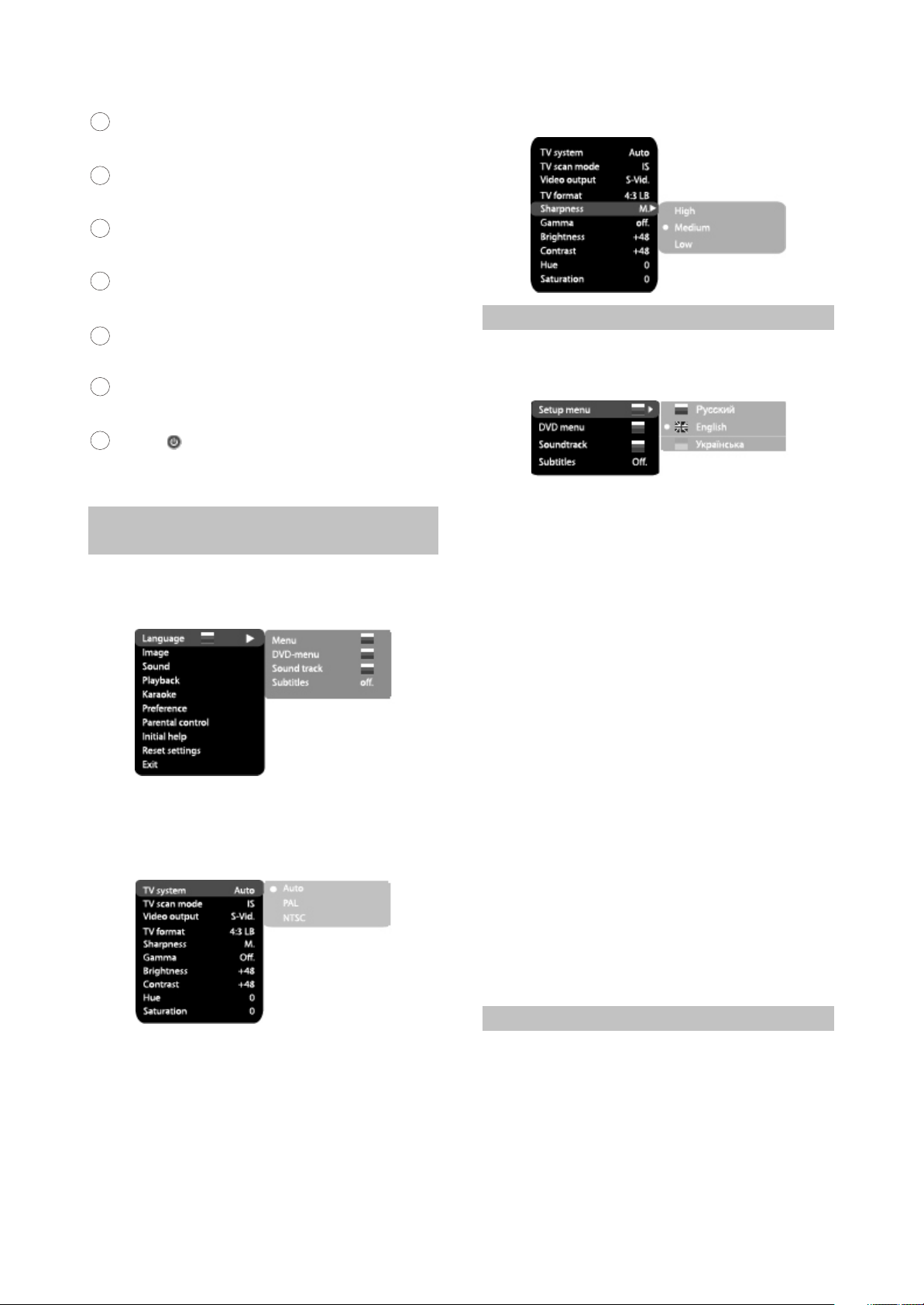
2.3 FUNCTION SETTINGS
2.3.1 Function selection and
change
Press the SETUP key to show the setup
menu. You will the following image on the screen,
as shown on the figure:
1.For example, if you wish to change the change
the image settings, you have to select the
image item and press the OK or RIGHT key of
the cursor joystick.
2.Using the jog Dial, select the desired item and
press OK or RIGHT key of the cursor joystick.
For example, select the Sharpness item.
Settings will appear on the screen. Then select
the desired sharpness level and press OK for
confirmation.
3.Press LEFT key of the cursor joystick for exit to
previous menu level.
2.3.2 Language settings
1.Menu: interface language setup
#Options: Russian, English, Ukrainian
#Default option: English
2.DVD-menu: selection of disc menu language
3.Soundtrack: selection of translation language
#Options: Russian, English, Estonian,
Lithuanian, Kazakh, Romanian, Belarusian,
Ukrainian, Chinese.
#Default: English
#Selection of other languages: select the
OTHERS item using the jog Dial and press OK.
Enter the language code using the numeric
buttons and press OK.
#If the language you selected is not recorded on
the DVD disc, another available language will
be used.
4.Subtitles: selection of subtitles language
#Options: Off, Russian, English, Estonian,
Lithuanian, Kazakh, Romanian, Belarusian,
Ukrainian, and Chinese.
#Default option: Off.
#Selection of other languages: select the
OTHERS item using the jog Dial and press OK.
Enter the language code using numeric
buttons and press OK.
#If the language you selected is not recorded on
the DVD disc, another available language will
be displayed.
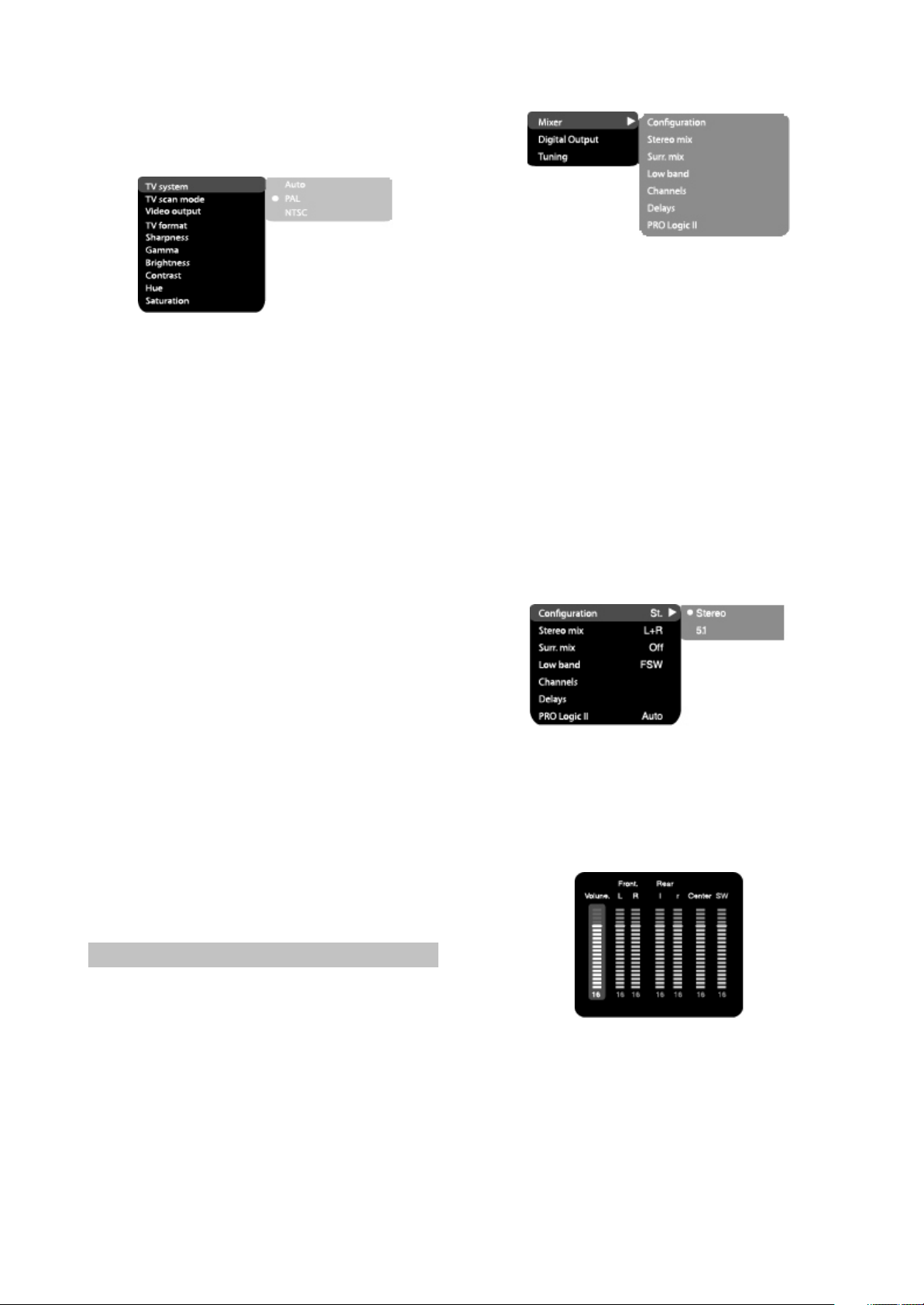
2.3.3 Image settings menu
1.TV system: TV system selection
#Options: Auto, PAL, NTSC
#Default option: PAL
2.TV scan mode: scan mode selection
#Options: progressive, interlaced
#Default option; Interlaced
#Progressive scan is transferred only via a
component video output.
- 8 -
#Before switching to progressive scan, make
sure that your TV set supports this operation
mode.
3.TV Format: image ratio settings
#Options: 4:3 pan&scan, 4:3 letterbox and 16:9
TV.
#Default option: 4:3 letterbox.
#Some discs are recorded with support of only
one ratio. The selected ratio must comply with
the TV screen.
4.Video output: selection of video signal
#Options: S-Video(only for DK14**SI Series),
Comp, SCART.
#Default option: Comp
5.Sharpness: image sharpness adjustment
#Options: High, Medium, Low
#Default option: Medium
6.Gamma: adjustment of image color
temperature
#Options: High, Medium Low, Off
#Default option: Off
7.Brightness: adjustment of image brightness
8.Contrast: adjustment of image contrast
9.Hues: adjustment of image hues
10.Saturation: adjustment of image saturation
Adjustment of image brightness, contrast, hues
and saturation:
#Select the desired item of the image adjustment
section using the jog Dial. Press OK or RIGHT
key to start adjusting the relevant option
#Change the option value using the jog Dial.
#Upon completion press the LEFT key of the
cursor joystick to return to image setup menu.
2.3.4 Sound settings menu
1.Mixer
a)Configuragion: setting of the mode conversion
of the 5-channel signal to stereo signal
#Options: Stereo, 5.1
#Default option:5.1
#5.1 mode must be supported by the disc.
Number of music accompaniment channels
depends on the specific disc.
#Adjustment of th4e central speaker and
surround speakers is available only if the
Configuration option is set to 5.1 position.
b)Stereo mix: playback set-up while playing the
disc with two independent audio channels
#Options: L+R, L, R
#Default options: L+R
c)Surr.mix: set-up of surround options while
playing the stereo disc.
#Options: Off, Sum. L+R,Virt.Surr.
#Default options: Off
d)Low band: distribution of low frequencies
through channels
#Options: Front F, Center C, Surround Sr,
Subwoofer SW
#Default options: Front F, Subwoofer SW.
#If you want the low-frequency component of the
sound signal enter only the subwoofer channel,
select and confirm the parameter Subwoofer
SW.
e)Channel settings: separate adjusting of
volume by channels.(only for DK14**SI Series)
#Select the channel you want.
#Adjust the sound volume of each channel using
the wheel.
#Press the OK to return to sound settings menu.
f)Delay of the channel: set-up of signal delay in
speaker channels(central, rear and subwoofer)
#Using the jog Dial, select the channel for which
you want to set up the delay, and press OK for
confirmation.
#Using the jog Dial set up the desired distance
from the listener to each speaker(detailed
description of this operation see on page 32).
- 9 -

#Press LEFT key of the cursor joystick to return
to speaker configuration menu.
g)PRO Logic ll: function of stereo sound
conversion to 5-channel sound
#Options: On, Off, Auto
#Default option: Off
#In Auto position, the DVD receiver determines
itself, when to use the PRO Logic ll decoder.
Some discs do not support this function.
2.Digital audio output
a)SPDIF format: set-up of digital audio output
options
#Options; RAW, PCM
#Default options; RAW
# When you select the RAW option, the not
decoded signal is transferred to the DVD
receiver’s digital outputs, the decoded signal is
transferred to analog outputs. Decoding is
performed by the built-in decoder of the DVD
receiver. This feature is meant to ensure that
signal decoding at digital outputs is performed
by an external device(e.g.an amplifier).
#If you select the PCM option, a PCM coded
signal will be transferred to the DVD receiver’s
digital outputs.
b)LPCM: set-up of digital audio output options to
comply with different amplifiers an d receivers
#Options: 48kHz 16 bit, 96 kHz 24 bit .
#Default option: 48kHz 16 bit.
3.Sound correction
a)Max volume: max volume limiting(only for
DK14**SI Series)
#Using the jog Dial, adjust the max volume level.
#Press the LEFT key of the cursor joystick to
sound correction setup menu.
b)Equalizer: equalizer modes
#Options: Rock, Pop, Live, Dance, Techno,
Classic, Soft.
#Default option: Off.
c)Echo; echo effects
#Options: Off, Concert, Living room, Hall
Bathroom Cave, Arena, Church
#Default option: Off
d)Tone balance: adjustment of tone balance
level.
#Adjust the tone balance level using the jog Dial
#Press the LEFT key of the cursor joystick to
return to sound correction setup menu.
2.3.5 Playback settings
1.DVD
Advertisment skip: skip the unskippable
block while playing a DVD disc.
#Options; Yes, No
#Default option: Number
#Press LEFT key of the cursor joystick to return to
speaker configuration menu.
2.VCD/SVCD
PBS menu: PBC menu on/off
#Options: On, Off
#Default option: On
#If On option is set, while erproducing discs, a
menu will appear, in which you can select the
order of playing the disc content. If the Off
option is set, the reproducing of content is
performed in the order, in which it is recorded
on the disc.
3.Files: selection of reproduced files on the disc
#Options: Audio, Pictures, Video All types.
#Default option: All types
4.Repeat: file repeat mode
#Options: Off, Single, All
#Default option: Off
5.Load effect: type of transition from one JPEG
file to another
#Options: Off, from top, from bottom
#Default option: Off.
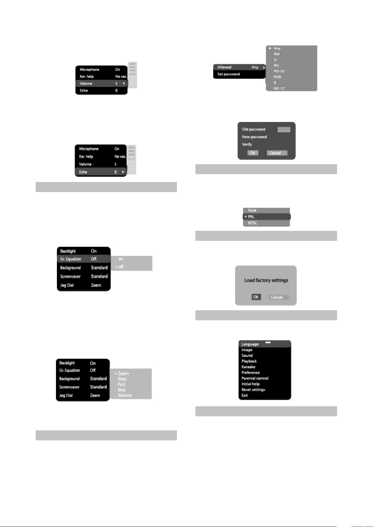
2.3.6 Karaoke settings menu
1.Microphone: microphone on/off
#Options: On, Off
#Default option: Off
2.Kar.help: karaoke-disc playback mode
#Options: L Channel, R Channel, No ast, No voc
#Default option: No vocal mode
3.Volume:
Microphone: microphone sound volume
level
#Using the jog Dial adjust the microphone
volume level.
- 10 -
#Press LEFT key of the cursor joystick to return
to karaoke settings menu.
4.Echo: echo level while playing the karaokedisc
#Adjust the echo level Using the jog Dial
#Press LEFT key of the cursor joystick to return
to karaoke settings menu.
2.3.7 Preference settings
1.Backlight: Selection of open/colse button LED
#Options: On, Off.
#Default option: On
2.Gr.Equalizer: spectrum analyzer
#Options: On, Off
#Default option: Off
2.Set password: setup of a four-digit password to
change the level of age restrictions
#Default option: 7890
2.3.9 Initial setup menu
#Press the RIGHT key of the cursor joystick to
enter the initial setup menu, then select the
desired item using the jog Dial and press OK
key for confirmation.
2.3.10 reset to defaults
Resetting all settings and restoring default
options, except age restrictions level and
password
3.Background: selection of an image as TV
screen wallpaper
#Options: Standard, Saved
#Default option: Standard
4.Screensaver: screen saver on/off
#Options; On, Off
#Default option: On
5.Jog Dial
#Options: Zoom, Step, Fast, Skip, Volume
#Default: Zoom
2.3.8 Parental Control
1.Category: setup of age restrictions to prevent
children from seeing undesirable discs
#Options: Any, Kid, G, PG, PG-13, PGR, R, CN-
17
#Default option: Any
2.3.11 Exit settings menu
#Select the exit item using the jog Dial and press
the OK to exit the menu.
2.3.12 Channel delay set-up
Set-up of time delay in the surround
channel
Usually, time delay in the Dolby digital
decoding system is preset to ensure best effect
while installing the Home Theater. However, in
case you wish to adjust your system more
precisely, please consult instructions given in
this manual.
- 11 -

Set up of tie delay for this device is possible
Dolby Digital Dolby Pro Logic s urround
Rear channel Stereo 20 Hz-20khz Mono channel w ith limited friquenc y range( 100 Hz-7khz)
in both Dolby Digital and Dolby Pro Logic modes..
To set the desired delay you have to know
the distance from the place where you are, to the
front speakers and Surround speakers as shown
in Fig.1. Consult Fig.2(Dolby Pro Logic mode)
and 3(Dolby Digital mode)in order to determine
the distance to Surround speakers(axis Y in the
figure)and the distance to the front speakers
(axis X in the figure). Crossing point of those two
lines on the chart will give the recommended
delay value.
Set-up of time delay in the central channel
Sometimes several people are listening to
the music, and the space is limited. In this case,
you can install three speakers(two front ones
and a central one)as shown in Fig.1 with the
distance to the listener being approximately the
same. The central channel delay is to be set at
“0”.
Should the central speaker be in close
proximity to left and right front speakers as
shown in Fig.2, or the central speaker be nearer
to listeners when compared with front speakers’
location, or the central speaker be nearer to the
listener by 1 foot, in all these cases you may set
the delay value for the central channel at 1 ms.
For instance, as shown in Fig.2, if the line C
is by 1 foot shorter than the lines R and L, the
delay value is to be set at 1 ms. If your sofa is
broad enough, and there are several listeners
sittings on it.
It makes sense to locate the speakers in
one line, as shown in Fig.3 with the delay value
of the central channel to be set at “0”. Finally, if it
will be necessary to install the central speaker
behind the left and right front speakers, the delay
value shall be set at “0”.
“Night” mode
The Dolby Digital system provides an
extremely broad dynamic range of playback
sound-from gentle to roaring. It creates the
presence effect, especially while seeing motion
pictures. However, at night a powerful sound
with a broad dynamic range may give pleasure to
you, but disturb and annoy your family and
neighbors. If you just decrease the volume, you
will immediately notice that you ceased to hear,
e.g., Dialogues as clear as you do at normal
volume, and such sound effects as rustle,
whisper etc have merely disappeared. To avoid
this, you just have to decrease the volume of
“loud”sounds by simultaneously increasing the
volume of “soft”sounds with the volume of
“average”sounds left unchanged, i.e.just
decrease the dynamic range of sound
accompaniment. Only Dolby Digital system
provides for such a method of sound control. It
uses the principle of compressing the acoustic
signal’s dynamic range while recording;
therefore, while playing an inverse
transformation(volume expansion)takes place.
This is called”night”mode. The regulation limits
are restricted, however, to avoid distortions of
resultant signal.
- 12 -
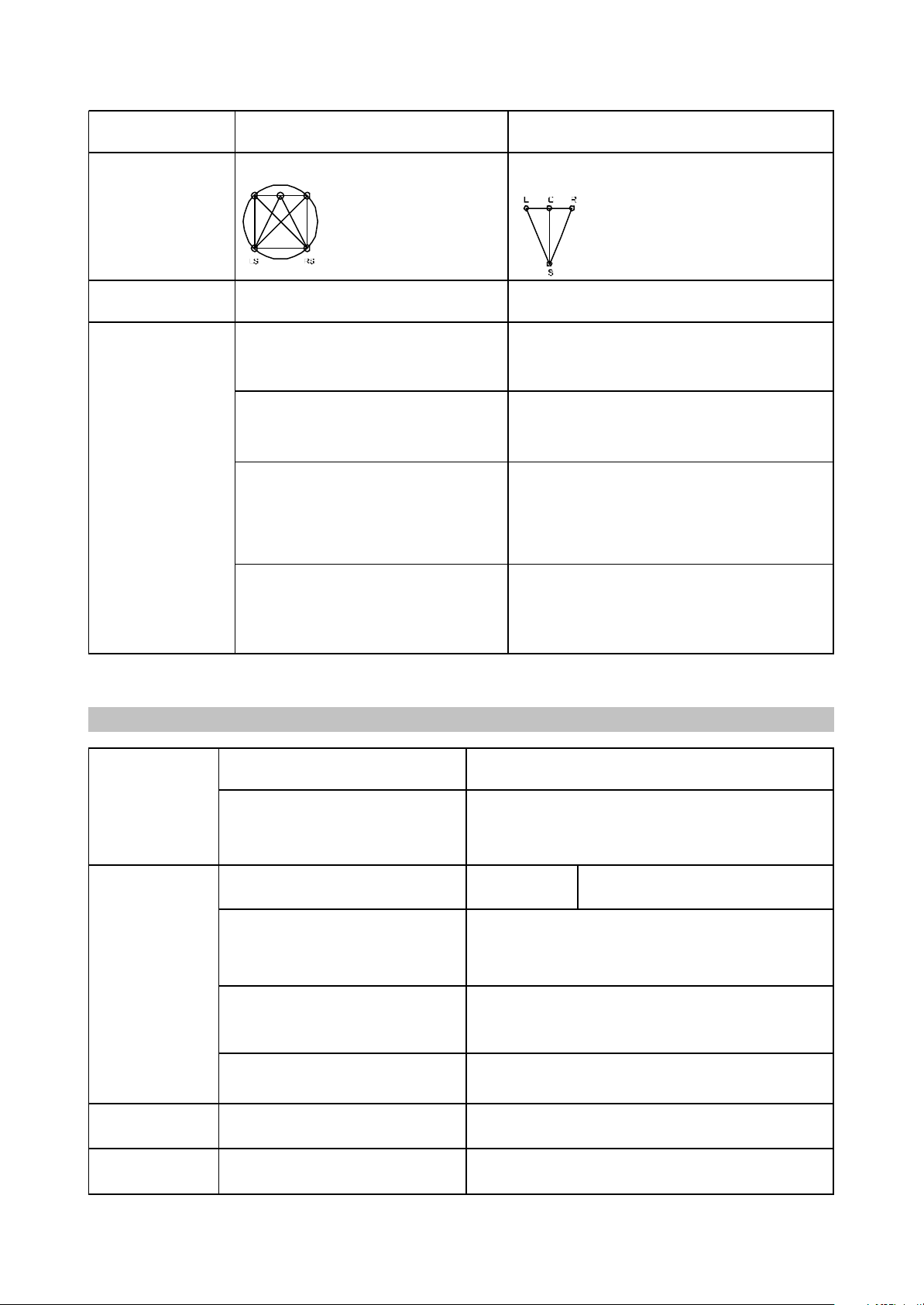
multivar iate From left to r ight, from right to left, f rom front to r ear,
fr om rear to fr ont
Low-frequency
Playback disc s
Input
Output Audio output
Analog audio output: Stereo
Digital audio output: Coaxial, Optical
Video char acteris tics
Audio char acteris tics
Operating voltage
Power consumption
FM Tuner
Frequency r ange
Channel separation
AM Tuner Frequency r ange
DVD receiver
DVD receiver
~220V,50/60 Hz
250W
87.5-108 MHz
>35dB
522-1611kHz
DV D-V ide o, Super V CD, V CD, Div X 4 , Div X 5 , Di v X Pr o, Xv iD,
CD-DA , CD+G, HDCD, MP3, W MA, K odak Pi ctu re CD, JPEG
2 MIC jacks
FM antenna input
AM antenna input
Stereo audio input(AUX)
Video amplitude: 1.0Vp-p(75Ù)
S-Video amplitde: Y:0.7vP-P(75Ù)
Component video amplitude: C:0.286vP-P(75Ù)
1.0vP-P(75Ù)
Frequency r esponse 20- 20000Hz(±1 Db)
Signal-to-noise ratio >90(dB)
THD <1 %
channel(subwoofer)
Sound field distribution
Available, 20-120Hz
N/a
Sound field distribution
Miscellaneous
6 Independent channels, each
reproducing its own signal at a time
Creates an optimum sound field
with illusion of an equal distance
from listener to each speaker.
Allows adjusting the decompression
degree of an equal distance
from listener to ecach speaker.
Possilility of programmable control of the
decoder to transfer basses into
low-frequency channel in systems
equipped with broad-band speakers
and a subwoofer.
Undoubted progress in sound recording
technology, especially important for
program directors, film directors, sound
engineers and actors.
2.4 Technical characteristics
4 segmented channels. Only one
channel is decoded at a time.
The most cost-efficient way to ensure
high-quality surround effect.
Surround sound may be received
from any signal source.
Compatible with existing and future
two-channel(stereo)formats.
Big progress in comparison with conventional
stereo, the world's most popular surround format.
- 13 -

Speaker sys tem
Output pow er RMS, 10% THD, 1 kHz
Subw oofer (40Hz)
Front channel
Rear channel
Center channel
Maximum power
Subw oofer
Front channel
Rear channel
Center channel
Operating
temperature
Operating humidity
Dimensions of DVDreceiv er
Weight of DVDreceiv er
Dimensions of
speakers
Subw oofer
Front channel
Rear channel
Center channel
DK1110SI DK1112SI DK1114SI
25 25 25
12 12 12
12
40 50 50
20 20 20
20 20 20
DK1110SI DK1112SI DK1114SI
325×310×200 325×310×200 325×310×200
80×101×165 80×101×165 150×90×86
80×101×165 80×101×165 150×90×86
80×
5-35
15-75%(no c ondensation)
60×380×350mm
3.4kg
- 14 -

ChapterThreePrincipleandServicing
SectionOnePrincipleofthePlayer
3.1.1 Function and features
# Progressive scanning output to produce steadier and clearer pictures without flickering.
#
Composite video, S-video, component video output.
#
Digital picture adjustment to the sharpness, brightness, contrast, chroma and saturation of
pictures, gamma correction.
#
Built-in Dolby digital decoder. Karaoke function.
#
Hi-Fi stereo headphone output. 5.1CH output.
#
Power amplifier adopts high performance large power IC with complete protection function and
perfect sound quality.
#
Compatible with DIVX, MPEG4 format disc.
#
Subwoofer adopts large diameter bass unit matched with large capacity speaker body.
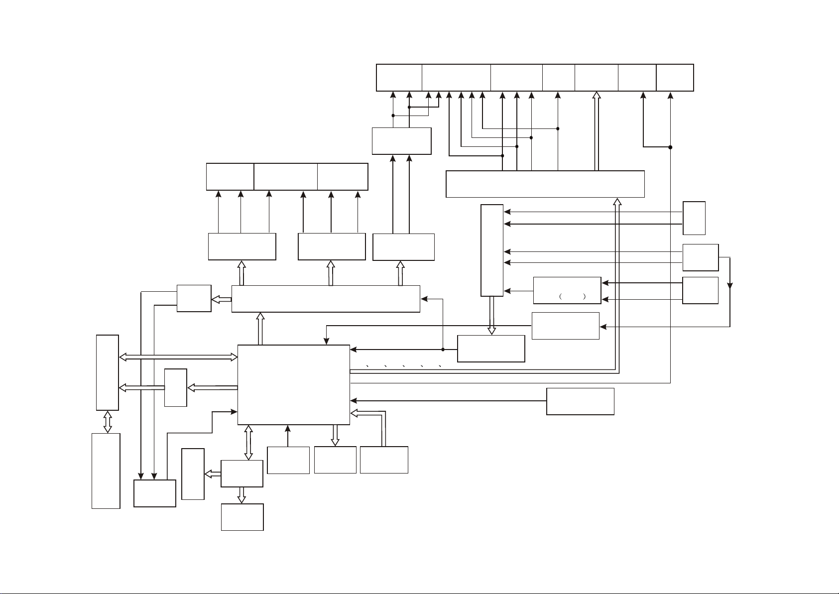
3.1.2 Bl
Its internal structure is mainly composed of decode & servo board, power amplifier board,
input/otuput board, panel, headphone board, tuner, power board and loader. The principle block diagram
is shown as the figure 3.1.2.1. All other signal flow is shown in figure except power board. The function
of loader is to read disc information and transmit it to Mt1389, which performs servo function through
D5954 on decode board and other supplementary circuit, and ensues the normal working of loader.
FLASH on decode board is to store system program, SDRAM is to store program and sound/image
information read from disc when the player is working to ensure their smooth output. The main function
of power amplifier board is to perform audio D/A conversion, amplify analog signal and output 5.1CH to
ensure the normal working of external speakers. The main function of AV board is to output various
audio signals. This player is also with headphone and microphone to meet customers’ demand. Further
more, it also has external sound input, which may amplify power by use of power amplifier board of this
ock diagram of the player
player to output to speaker. Tuner in this player makes it have tuning function. It is also equipped with
SAA6558 chip to realize RDS function of Europe and RBDS function of US.
- 15 -
ROUTX
L R
LOUTX
SCART
Y
Cr/Cb
Pr/Pb
Video S-video
VIDEO COMP
VEDIOC VIDEOY
Optial
Coaxial
Filtering
VY
Front
Rear
L R
SLOUT
Rear
SROUT
Woofer
SW+ SW-
Center
CEN
Front
L
R
FROUT
FLOUT
CD4052
N13
TAS5112
N11
LM4880
HR
HL
N12 TAS5508
SDAT A0
SDAT A1
SDAT A2
XS301
D5954
U201
MT1389HD
N14
TAS51 12
DAVNIN
Amplifying circuit
N8, N9 (TLV272)
SDA AD
ADC DAT
Y1 Y2 Y3 Y4 Y5 Y6
SPDIF
URST#
CS5340
VV
VU
Filtering
AUXR
AUXL
TUL
TUR
OK
Amplifying circuit
N1 4558
N6
SAA6558
Reset circuit
MIC 1
MIC 2
PDS MPX
L
R
Tuner
MIC
External
audio
input
- 16 -
Figure 3.1.2.1 Block diagram of the player
Loader
Headphone
HDET
VFD screen
CLK
STB
SDA
N101
AD7312
Button
IR
N102
REMOT
IR receiver
U214
FLASH
U211
SDRAM

3.1.3 Introduction to IC used in this player
PCB sem i-finishe d
product name
IC model Locat ion Function
MT1389HD U201 Decode chip
24C02 U202 EEPROM
RT9701 U203
HCU04 U205 Phase inverter
LM1117 U209 Precision voltage stabilizer
HY57V641620HGT-7 U211 64M SDRAM
29LV160BE U214 16M FLASH
D5954 U302 Servo drive
4558 N1 Audio amplifying
SN74LVC N2 Phase inverter
74HCT125 N3,N4 Buffe r
CD4052 N5 Audio mixing
SAA6588 N6 Tuning IC
CS5340 N7 A/D conversion
TLV272 N8,N9 Operational amplifier
LM4880 N11 Audio amplifying
TAS5508PAG N12 Pulse width adjuster
TAS5112DFD N13,N14 Digital power amplifier
PT2597 N15
AD7312 N101 Panel control IC
REMOT N102 Remote control receiver
VIPER22 U501 Power switch IC
HS817 U502,U506 Photoelectric coupler
TL431 U503,U507 Precision voltage stabilizer
LM7805 U504 Voltage stabilizing tube
KA1M0880BTU U505 Power switch IC
decode board
Power a mplifie r
board
Powe r boar d
Main pa nel
Introduction to IC used in DK1910SI is shown in the following table:
- 17 -

Section Two Unit Circuit Principle
Pin Name
Signal flow
direction
DVD disc CD disc No disc Function description
1 F- Input loader 2.52 2.34 0.46
2 F+ Input loader 2.49 2.49 0.93
3 T+ Input loader 2.53 2.51 0.94
4 T- Input loader 2.58 2.51 0.93
5 C Input MT1389 2.2 2.25 2.04 Disc data signal
6 D Input MT1389 2.2 3.2 2.04 Disc data signal
7 IOA Input MT1389 0.01 3.2 3.21
Disc identification signal, CD is 3.3V, DVD
is 0V
8 RF Input MT1389 2.21 2.53 1.28 The sum of disc data signal
9 A Input MT1389 2.17 2.22 2.04 Disc data signal
10 B Input MT1389 2.19 2.27 2.04 Disc data signal
11 F Input MT1389 2.07 2.44 2.03 Supplementary signal used in trace
12 GND Ground 0.01 0.01 0 Grounding
13 V20 Input loader 2.04 2.06 2.03 Reference voltage
14 Vcc Input loader 5.04 5.04 5.02 Supply voltage for loader
15 E Input MT1389 2.06 2.45 2.03 Disc data signal
16 Blanking haning in air 0.01 0 0 unused
Focus error signal is added to two sides of
pick-up focus coil
Trace error signal is added to two sides of
pick-up trace coil
3.2.1 Introduction to laser head
1. Function introduction to laser head flat cable is shown as the following table:
- 18 -

Note: 1. When reading DVD, there are only A, B, C, D signals.
17 VR-CD Input loader 0.21 0.01 0
Through the handling inside loader, make
sure MD11 is 180mV when reading CD
18 VR-DVD Input loader 0.01 0.2 0
Through the handling inside loader, make
sure MD11 is 180mV when reading DVD
19 LD-CD Input loader 0.09 2.1 0 CD laser power control signal
20 MDI I Input MT1389 0.21 0.2 0
CD and DVD laser power monitoring
signal
21 HFM Input loader 5.04 5.04 5.02
High frequency overlapping signal
produces laser with different wave length
inside loader
22 Blanking unused 0.01 0.1 0
23 LD-DVD Input loader 2.21 0.1 0 DVD laser power control signal
24 GND unused 0.01 0.01 0 Grounding
2. When reading CD, there are A, B, C, D, E, F signals.
3. RFO=A+B+C+D.
4. Focus error signal=(A+C)-(B+D) Trace error signal=E-F.
2. Working principle
(1) Laser tube: wave length of loader DVD laser diode is 650nm, wave length of CD laser diode is
790nm, the wave length which is within 370nm and 750nm is visible light, the laser in the course of
reading DVD disc is visible light, and that when reading CD disc is infrared light.
(2) Principle about laser head picks up signal: laser beam projects onto disc, when laser beam focus
projects onto disc vertically, laser beam will produce reflection, reach on light sensor through reflection
loop and converse into electronic signal through photoelectric cell. For the reflection loop produced in
non pit information area and pit information area in disc has difference and reflects into different position
of light sensor, photoelectric diode in different positions on light sensor will produce different signals to
process all signals on light sensor and then produce digital signals.
(3) Focus, trace coil: when laser head is reading signals normally, information side should be in the
focus of laser beam, because of factors of disc error, high speed rotation and machine error, it is
unavoidable that laser beam focus deviates from information face to produce phenomena of orbit boas
and refocusing. Focus , trace coil is added on loader to adjust laser beam to make it correctly focus in
information area.
(4) Formation of RF signal: when disc reading is normal, light sensor will have 160MV, vague and
eye pattern waveform which is added on A, B, C, D respectively, and output RF signal from FRO pin after
being overlapped by adder inside light sensor, the frequency when reading DVD disc is much higher
than that when reading CD disc, output amplitude is about 1.4V.
- 19 -

3.2.2 Servo circuit
1. DK1910S adopts SANYO 62 decoder and MTK decode solution (MT1389+FLASH
(16M)+SDRAM (64M)). The servo circuit is mainly composed of front signal processing, digital servo
processing, signal processing IC T1389 and drive circuit D5954, in which MT1389 is the main
component of decode circuit at the same time, shown as the figure 3.2.3.1:
Loader
Feed electric
machine on loader
Disc in/out electric
machine and
detecting switch
DVD laser power control
VCD laser power control
Disc identification circuit
18
23
21
22
Main axis
braking circuit
Disc in/out circuit
Main axis electric
machine on loader
Integration circuit
Integration circuit
Integration circuit
Integration circuit
Figure 3.2.2.1 Servo circuit diagram
2. Working principle: after powering on or disc in, according to IOA signal, disc identification circuit
decides through which path of variable resistor the laser detecting diode gets path to the ground,
meanwhile MT1389 decides whether DVD laser or VCD laser is emitted according to IOA signal, which
can be fulfilled through laser power control circuit. When IOA is high level (3.3V), Mt1389 pulls LOD1 of
V302 base electrode in laser tube power control connected to VCD down to about 2.2V to make V302 on
and to make VCD laser tube emit beam; then decides whether to pull up or pull down LOD1 according to
voltage after the feedback from MDI1 to control the power of light emission diode. Similarly, when IOA is
low level (0V), MT1389 pulls LOD2 of V301 base electrode in laser tube power control connected to
- 20 -

DVD down to about 2.2V to make V301 on and to make DVD laser tube emit beam; then decides
whether to pull up or down LOD2 according to the voltage after the feedback from MDIAfter loader
reading disc information, A, B, C, D, E, F signals are sent out to Mt1389 (DVD only has A, B, C, D
signals), and then inputted from pin 2~11, 18, 19 of MT1389. After being amplified and processed by the
pre-amplifier inside MT1389, now signals are separated to two part s for processing inside Mt1389.
After being processed by digital servo signal circuit inside MT1389, one part of signal form
corresponding servo control signals and output FOO, TRO, DMO, FMO digital servo control signals from
pin 42, pin 41, pin 37, pin 38 of Mt1389 respectively, then change into analog servo control signal FOSO,
TRSO, DMSO, FMSO through integration circuit composed by resistor capacitor, and send to driver
circuit BA5954 for amplification to bring along focus coil, trace coil, main axis electric machine and feed
electric machine after drive amplification. Among these, focus and trace servo are used to correct
objective position accurately; feed servo is used to bring along laser head to make radial large-scale
move which belongs to the preliminary adjustment to pick-up position;and main axis servo is used to
control main axis electric machine to make it read signals in means of constant linear velocity and bring
along disc to rotate.
After processing of amplification by VGA voltage control amplifier and equalization frequency
compensation inside MT1389, another part of signals are changed into digital signals through internal
A/D converter. When loader is reading CD/VCD signals, these signals are conducted EFM demodulation
inside MT1389, and then outputted to latter stage for AV decoding after finishing CIRC (Cross-
Interleaved Reed-Solomon Code) error correction inside. When loader is readingDVD signals, these
signals are conducted ESM demodulation inside MT1389, and then sent to latter stage for decoding
after finishing RSPC error correction inside.
The other part of servo is open/close disc tray circuit. After panel or remote controller emits
open/close disc tray signal toMT1389, in usual conditions, TROPEN and TRCLOSE sent out by pin 39,
51 of Mt1389 are both low level, when signal of “open” comes, after Mt1389 makes disc stop rotating
through main axis braking circuit, TRCLOSE is set high to make open/close electric machine on loader
frame run to bring along dist tray to eject. After disc tray ejecting to proper Signal of opening to proper
position (TR_OUT) is set high level (0V) through the detecting switch on loader frame, MT1389 pulls
down TRCLOSE and open/close electric machine stop running. When MT1389 receiving “close” signal,
TROPEN is set high level by MT1389, open/clode electric machine tuns conversely to bring along disc
tray to close. After disc tray closing to proper position, signal of closing to proper position (TR_IN) is set
low level through the detecting switch on loader frame, MT1389 pulls down TROPEN and electric
machine stops running to finish “close” process.
3. Explanation to servo terms
FOO: when rotating, disc may probably move upwards or downwards slightly to make the focus of
laser emitted by pick-up cannot justly fall on data pit of disc, so pick-up is required to move upwards or
- 21 -

Downwards to make focus aim at data pit justly. When pick-up is moving upwards or downwards, it
Name
When reading
disc nor mally
When disc out When disc in
When no disc
in
TRO PEN 0
There is about 1 sec ond 3.3V pulse
w hen at the moment of dis c out
0 0
TRCLO SE 0 0V
There is about 1 sec ond 3.3V pulse w hen
at the moment of dis c out
0
TROUT 3.41V 3.3V 0V 0V 3.3V 3.3V
TRIN 0 0V 3.3V 3.3V 0V 0
OPO 2.61V 2.75V 2.64V 2.61V
ADIN 2.61V 2.76V 2.61V 2.61V
OP+ 1.66V 1.81V 1.27V 1.81V
OP- 1.85V 2.12V 1.47V 2.04V
means that pick-up is making focus acts.
TRO: data information is save in disc in form of tracks. The process when pick-up moves from one
track to another one to read data is trace. In this process, it is objective, but the entire pick-up, that
moves forwards or backwards, and the moving range is very small.
FMO: similar to acts of trace, the acts of feed are larger than those of trace. Feed conducts a large
scale movement firstly, and then trace moves slightly in this range. Feed moves for a while, and does not
move for another while; but Trace moves all the time. Feed is rough adjustment and trace is fine.
DMO: it is the top that holds up disc. Its rotation speed decides that of disc. Its rotation is generated
by an individual DC electric machine, in which rotation speed of DVD is twice over that of CD.
Hint: In order to observe these processes, you may take down upper cover of the machine, and then the
loader cover board. When power on with no disc in or disc in after disc out, you may observe that pick-up
returns to inner ring firstly and then springs back for a little distance, which is feed process. Then pick-up
will emit light and you may notice the objective moves upwards and downwards, which is focus process.
In face, in the same time of focus, the objective also moves upwards and backwards to make trace acts.
Because the range is small, it is not easy to observe, and meanwhile DEMO disc tray also rotates
slightly, which is DEMO acts.
4. Voltage of key point is shown as follows:
- 22 -

3.2.3 Main axis braking control circuit
1. Main axis braking control circuit is shown as the following figure 3.2.3.1:
Figure 3.2.3.1 Main axis braking control circuit diagram
The equivalent circuit is shown as the following figure 3.2.3.2:
Figure 3.2.3.2 Main axis braking control equivalent circuit diagram
50
Internal
processing
2. Working principle: To prolong the service life of electric machine and decrease the influence of
start-up concussion current to the machine, when there is disc in, the development personnel design the
main axis electric machine in running state always. Even though “STOP” button is pressed, disc will not
stop running immediately. Thus when pressing “OPEN” button, a braking signal is required to make the
main axis electric machine stop running to fulfill the completion of opening disc tray in a short period.
- 23 -
In the course of playback, press “OPEN" button and main axis drive signal disappears. For the
Key point Position Normal w orking voltage (V) Voltage change w hen disc out ( V)
SP+ Pin 11 of D5954, pin 5 of XS303 3.79 3.79 0.70 1.80
SP- Pin 12 of D5954, pin 6 of XS303 1.38 1.38 3.40 1.80
OP+ Pin 36 of MT1389/B 1.38 1.38 3.10 1.80
OP- Pin 35 of MT1389/A 1.53 1.53 3.08 1.98
OPO Pin 34 of MT1389/C 2.44 2.44 0.40 2.50
ADIN Pin 47 of MT1389/D 2.44 2.41 0.41 2.44
DMSO Pin 5 of D5954 1.42 1.42
VIP4 Pin 30 of MT1389 1.41 1.41
reason of inertia, the main axis electric machine is still in running state, and now the induced voltage
achieved by the induced electromotive force which is generated by electric machine's running on
sampling resistor R321 and R340 outputs from pin 34 through resistor R319, R320 and pin 35, 36 of
MT1389 after being processed inside MT1389 and magnified, then sends to pin 50 of MT1389 through
R13; after A/D conversion and the corresponding processing inside MT1389, an instant electric machine
reversal braking signal is outputted from pin 37 of MT1389 to make the main axis electric machine
decrease speed. When MT1389 detects the disc stops running, disc tray will open to ensure that disc
will not run when disc tray opens.
3. Key point voltage (unit: V), shown as the following table:
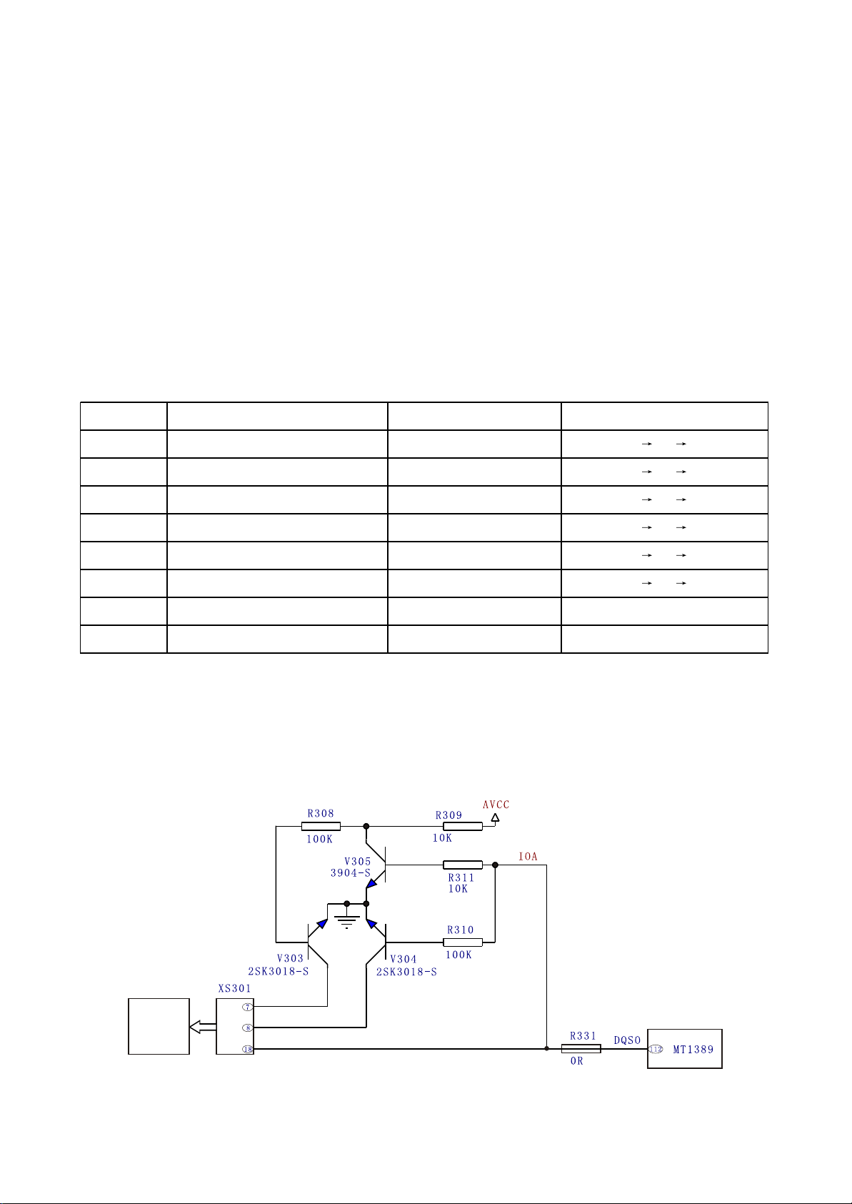
3.2.4 Disc identification circuit
1. Disc identification circuit is shown as the following figure 3.2.4.1:
Loader
Figure 3.2.4.1 Disc identification circuit diagram
- 24 -

2. Working principle: the function of disc identification circuit is to identify the disc inserted to loader
and judge whether the disc is VCD or DVD to perform the corresponding control acts. When disc is
inserted in, decode servo control IC MT1389 defaults disc to DVD. Pin 112 of MT1389 outputs a low
voltage signal, V305 and V304 are cut off, V303 is on, laser receiver tube inside loader selects DVD
channel, now IOA is low level input loader to make loader in the state of reading DVD, through detecting
laser power feedback signal, MT1389 analyses whether the preliminary judgment is correct (disc is
defaulted DVD). When detecting correct preliminary judgment, loader runs in the state of reading DVD;
when detecting incorrect preliminary judgment, MT1389 outputs a high voltage signal from its pin 112,
V305 and V304 are on, V303 is cut off, laser receiver tube inside loader selects VCD channel, now IOA
is high level input loader to make loader in the state of reading VCD. Whether the preliminarily defaulted
disc is VCD or DVD is set by MT1389 internal software.
Note: V303 and V304 are MOS tube.
3.2.5 Disc in/out circuit
1. Disc in/out circuit is shown as the following figure 3.2.5.1:
VCC
TC308
47uF/16V
LOAD-
(TRCLOSE1)
TROPEN
R323
1.5K
R325
470R
R326
2.2R\1/4W
V306
8550
V307
8050
Figure 3.2.5.1 Disc in/out circuit diagram
V309
8550
V308
8050
V310
9014-S
R324
1.5K
R327
470R
TC309
47uF/16V
R339
10K
LOAD+
(TROPEN1)
TRCLOSE
(TRCLOSE1)
TROPEN
2. Electric current when disc in/out
Open disc tray: VCC V306CE electrode on LOAD+ Electric machine LOAD- V308CE
electrode on R326 Ground
When not opening disc tray, pin 54 and 39 of MT1389 are low level. When opening disc tray, pin 54
of MT1389 sends a high level; V308 is on; V308 collector electrode changes into low level; LOAD-
changes into low level; V306 base electrode changes into low level; V306 is on. V306 collector electrode
changes into high level and LOAD+ changes into high level.
Close disc tray: VCC V309CE electrode on LOAD- Electric machine LOAD+ V307CE
electrode on R326 Ground
- 25 -
When closing disc tray, pin 39 of MT1389 sends a high level; V307 is on; collector electrode
Key point Position Voltage Remark
DV33 (point A) Diode VD201 cathode 3.3V
TC217 may sends out c urrent f rom this point
after pow er failure
changes into low level; LOAD+ is low level; base electrode through R324 and V309 is low level; V309 is
on; V309 collector electrode changes into high level; LOAD- changes into high level.
The function of V310 is interlock TRCLOSE and TROPEN signal to ensure the two are not high level
at the same time. When the two are high level input, base electrode of V308 is made to low level through
V310 on to ensure the normal working of disc in/out circuit. The function of electrolytic capacitor TC309
and Tc308 is to avoid the sudden change of the voltage on two ends of disc in/out electric machine to
make disc in/out acts smooth.
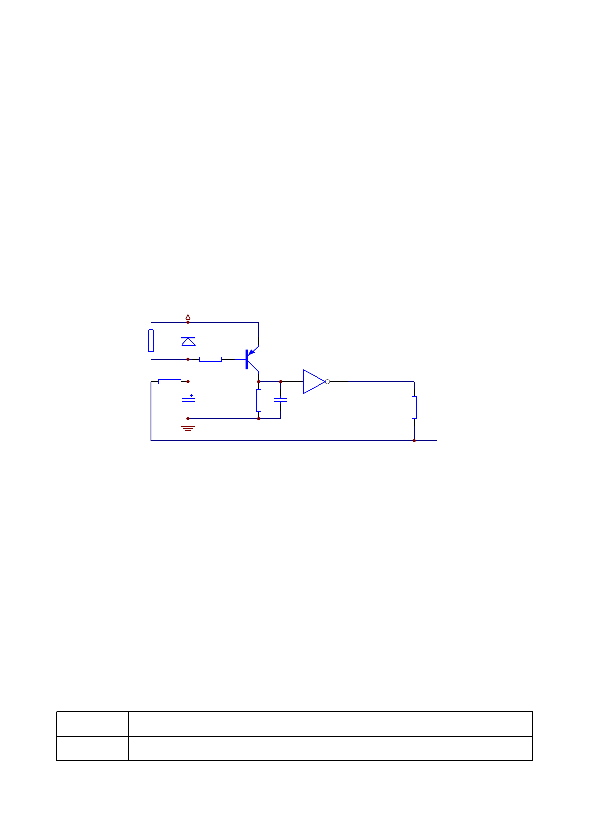
3.2.6 Reset circuit
1. Reset circuit is shown as the following figure 3.2.6.1:
DV33
A
R252
75K
R253
0R(DNS)
VD201
1N4148
R236
B
1K
TC217
47uF/16V
Q204
9015
R254
47K
C
5 6
C278
225
U205C
HCU04
R256
33R
URST#
D
Figure 3.2.6.1 Reset circuit diagram
2. Working principle: The two ends voltage of capacitor T217 cannot change suddenly, anode of the
capacitor begins charging from 0V and now triode Q204 is on. Pin 5 of phase inverterU205 (HCU04)
output port is high voltage and pin 6 of it is low voltage to reset chip MT1389 FLASH, TAS5508 and
Cs5340. When charge of the capacitor is close to 3.3V, triode Q204 cut off; pin 5 of phase inverter input
port is low level; phase inverter outputs high voltage from pin 6 and MT1389 reset finishes. After reset of
MT1389, reset signal is also given to sound D/A conversion chip CS4360 and sound A/D conversion
chip CS5340V for their resetting. In the course of system working, pin 214 of MT1389 outputs reset
signal to reset TAS5508 and CS5340 on power amplifier board.
3. Key point voltage is shown as the following table:
- 26 -
 Loading...