

SONY DEH 2150UB, DEH 2180UB Service Manual
PIONEER CORPORATION 4-1, Meguro 1-chome, Meguro-ku, Tokyo 153-8654, Japan
PIONEER ELECTRONICS (USA) INC. P.O. Box 1760, Long Beach, CA 90801-1760, U.S.A.
PIONEER EUROPE NV Haven 1087, Keetberglaan 1, 9120 Melsele, Belgium
PIONEER ELECTRONICS ASIACENTRE PTE. LTD. 253 Alexandra Road, #04-01, Singapore 159936
PIONEER CORPORATION 2008
CD RECEIVER
ORDER NO.
CRT4228
DEH-20UB/XS/UC
DEH-20UB
DEH-2150UBG
DEH-2150UB
DEH-2150UB
This service manual should be used together with the following manual(s):
Model No. Order No. Mech.Module Remarks
CX-3240 CRT4050 S10.5COMP2-iPod/USB CD Mech. Module : Circuit Descriptions, Mech. Descriptions, Disassembly
/XS/ES
/XU/CN5
/XS/ES
/XS/UC
For details, refer to "Important Check Points for Good Servicing".
K-ZZZ. OCT. 2008 Printed in Japan
1234
1234
C
D
F
A
B
E
SAFETY INFORMATION
CAUTION
WARNING
Where in a manufacturer’s service documentation, for example in circuit diagrams or lists
of components, a symbol is used to indicate that a specific component shall be replaced only
by the component specified in that documentation for safety reasons, the following symbol shall
be used:
This product contains certain electrical parts contain chemicals which are known to the State of
California to cause cancer, birth defects or other reproductive harm.
Health & Safety Code Section 25249.6 - Proposition 65
This service manual is intended for qualified service technicians; it is not meant for the casual do-it-yourselfer.
Qualified technicians have the necessary test equipment and tools, and have been trained to properly and safety repair
complex products such as those covered by this manual.
Improperly performed repairs can adversely affect the safety and reliability of the product and may void the warranty.
If you are not qualified to perform the repair of this product properly and safety, you should not risk trying to do so
and refer the repair to a qualified service technician.
CAUTION:
USE OF CONTROLS OR ADJUSTMENTS OR PERFORMANCE OF PROCEDURES OTHER THAN THOSE
SPECIFIED HEREIN MAY RESULT IN HAZARDOUS RADIATION EXPOSURE.
WARNING!
The AEL (accessible emission level )of the laser power output is less than CLASS 1
but the laser component is capable of emitting radiation exceeding the limit for
CLASS 1.
A specially instructed person should do servicing operation of the apparatus.
Laser diode characteristics
Wave length : 785 nm to 814 nm
Maximum output : 1 190 µW(Emitting period : unlimited)
Additional Laser Caution
Transistors Q101 in PCB drive the laser diodes.
When Q101 is shorted between their terminals, the laser diodes will radiate beam.
If the top cover is removed with no disc loaded while such short-circuit is continued,
the naked eyes may be exposed to the laser beam.
- Safety Precautions for those who Service this Unit.
When checking or adjusting the emitting power of the laser diode exercise caution in order to get safe, reliable
results.
Caution:
1. During repair or tests, minimum distance of 13 cm from the focus lens must be kept.
CAUTION
CLASS 1M INVISIBLE LASER RADIATION WHEN OPEN. DO NOT VIEW DIRECTLY WITH OPTICAL INSTRUMENTS
2. During repair or tests, do not view laser beam for 10 seconds or longer.
CAUTION
Danger of explosion if battery is incorrectly replaced.
Replaced only with the same or equivalent type recommended by the manufacture.
Discord used batteries according to the manufacture's instructions.
2
DEH-20UB/XS/UC
5678
56
7
8
C
D
F
A
B
E
[Important Check Points for Good Servicing]
In this manual, procedures that must be performed during repairs are marked with the below symbol.
Please be sure to confirm and follow these procedures.
1. Product safety
Please conform to product regulations (such as safety and radiation regulations), and maintain a safe servicing environment by
following the safety instructions described in this manual.
1 Use specified parts for repair.
Use genuine parts. Be sure to use important parts for safety.
2 Do not perform modifications without proper instructions.
Please follow the specified safety methods when modification(addition/change of parts) is required due to interferences such as
radio/TV interference and foreign noise.
3 Make sure the soldering of repaired locations is properly performed.
When you solder while repairing, please be sure that there are no cold solder and other debris.
Soldering should be finished with the proper quantity. (Refer to the example)
4 Make sure the screws are tightly fastened.
Please be sure that all screws are fastened, and that there are no loose screws.
5 Make sure each connectors are correctly inserted.
Please be sure that all connectors are inserted, and that there are no imperfect insertion.
6 Make sure the wiring cables are set to their original state.
Please replace the wiring and cables to the original state after repairs.
In addition, be sure that there are no pinched wires, etc.
7 Make sure screws and soldering scraps do not remain inside the product.
Please check that neither solder debris nor screws remain inside the product.
8 There should be no semi-broken wires, scratches, melting, etc. on the coating of the power cord.
Damaged power cords may lead to fire accidents, so please be sure that there are no damages.
If you find a damaged power cord, please exchange it with a suitable one.
9 There should be no spark traces or similar marks on the power plug.
When spark traces or similar marks are found on the power supply plug, please check the connection and advise on secure
connections and suitable usage. Please exchange the power cord if necessary.
a Safe environment should be secured during servicing.
When you perform repairs, please pay attention to static electricity, furniture, household articles, etc. in order to prevent injuries.
Please pay attention to your surroundings and repair safely.
2. Adjustments
To keep the original performance of the products, optimum adjustments and confirmation of characteristics within specification.
Adjustments should be performed in accordance with the procedures/instructions described in this manual.
4. Cleaning
For parts that require cleaning, such as optical pickups, tape deck heads, lenses and mirrors used in projection monitors, proper
cleaning should be performed to restore their performances.
3. Lubricants, Glues, and Replacement parts
Use grease and adhesives that are equal to the specified substance.
Make sure the proper amount is applied.
5. Shipping mode and Shipping screws
To protect products from damages or failures during transit, the shipping mode should be set or the shipping screws should be
installed before shipment. Please be sure to follow this method especially if it is specified in this manual.
DEH-20UB/XS/UC
3

1234
1234
C
D
F
A
B
E
CONTENTS
SAFETY INFORMATION ..................................................................................................................................... 2
1. SERVICE PRECAUTIONS ............................................................................................................................... 5
1.1 SERVICE PRECAUTIONS......................................................................................................................... 5
1.2 NOTES ON SOLDERING .......................................................................................................................... 5
2. SPECIFICATIONS ............................................................................................................................................ 6
2.1 SPECIFICATIONS...................................................................................................................................... 6
2.2 DISC/CONTENT FORMAT ........................................................................................................................ 9
2.3 PANEL FACILITIES.................................................................................................................................. 10
2.4 CONNECTION DIAGRAM ....................................................................................................................... 13
3. BASIC ITEMS FOR SERVICE........................................................................................................................ 14
3.1 CHECK POINTS AFTER SERVICING..................................................................................................... 14
3.2 PCB LOCATIONS .................................................................................................................................... 15
3.3 JIGS LIST ................................................................................................................................................ 16
3.4 CLEANING............................................................................................................................................... 16
4. BLOCK DIAGRAM.......................................................................................................................................... 18
4.1 BLOCK DIAGRAM................................................................................................................................... 18
5. DIAGNOSIS.................................................................................................................................................... 21
5.1 OPERATIONAL FLOWCHART ................................................................................................................ 21
5.2 ERROR CODE LIST................................................................................................................................ 22
5.3 CONNECTOR FUNCTION DESCRIPTION............................................................................................. 24
6. SERVICE MODE............................................................................................................................................ 25
6.1 DISPLAY TEST MODE ............................................................................................................................ 25
6.2 CD TEST MODE...................................................................................................................................... 26
7. DISASSEMBLY............................................................................................................................................... 27
8. EACH SETTING AND ADJUSTMENT ........................................................................................................... 30
8.1 CD ADJUSTMENT................................................................................................................................... 30
8.2 CHECKING THE GRATING AFTER CHANGING THE PICKUP UNIT.................................................... 31
9. EXPLODED VIEWS AND PARTS LIST.......................................................................................................... 34
9.1 PACKING ................................................................................................................................................. 34
9.2 EXTERIOR (1) ......................................................................................................................................... 36
9.3 EXTERIOR (2) ......................................................................................................................................... 38
9.4 CD MECHANISM MODULE..................................................................................................................... 40
10. SCHEMATIC DIAGRAM ............................................................................................................................... 42
10.1 TUNER AMP UNIT(GUIDE PAGE) ........................................................................................................ 42
10.2 KEYBOARD UNIT.................................................................................................................................. 48
10.3 CD MECHANISM MODULE(GUIDE PAGE) .......................................................................................... 50
10.4 WAVEFORMS........................................................................................................................................ 56
11. PCB CONNECTION DIAGRAM ................................................................................................................... 60
11.1 TUNER AMP UNIT................................................................................................................................. 60
11.2 KEYBOARD UNIT.................................................................................................................................. 64
11.3 CD CORE UNIT(S10.5COMP2-USB-C3).............................................................................................. 66
12. ELECTRICAL PARTS LIST .......................................................................................................................... 68
4
DEH-20UB/XS/UC

5678
56
7
8
C
D
F
A
B
E
1. You should conform to the regulations governing
the product (safety, radio and noise, and other
regulations), and should keep the safety during
servicing by following the safety instructions
described in this manual.
2. Before disassembling the unit, be sure to turn off
the power. Unplugging and plugging the connectors
during power-on mode may damage the ICs inside
the unit.
3. To protect the pickup unit from electrostatic discharge
during servicing, take an appropriate treatment
(shorting-solder) by referring to "the DISASSEMBLY".
4. After replacing the pickup unit, be sure to check the
grating.
5. Be careful in handling ICs. Some ICs such as MOS
type are so fragile that they can be damaged by
electrostatic induction.
For environmental protection, lead-free solder is used on the printed circuit boards mounted in this unit.
Be sure to use lead-free solder and a soldering iron that can meet specifications for use with lead-free solders for repairs
accompanied by reworking of soldering.
Compared with conventional eutectic solders, lead-free solders have higher melting points, by approximately 40 C.
Therefore, for lead-free soldering, the tip temperature of a soldering iron must be set to around 373 C in general, although
the temperature depends on the heat capacity of the PC board on which reworking is required and the weight of the tip of
the soldering iron.
Compared with eutectic solders, lead-free solders have higher bond strengths but slower wetting times and higher melting
temperatures (hard to melt/easy to harden).
The following lead-free solders are available as service parts:
Parts numbers of lead-free solder:
GYP1006 1.0 in dia.
GYP1007 0.6 in dia.
GYP1008 0.3 in dia.
1. SERVICE PRECAUTIONS
1.1 SERVICE PRECAUTIONS
1.2 NOTES ON SOLDERING
DEH-20UB/XS/UC
5
1234
1234
C
D
F
A
B
E
2. SPECIFICATIONS
General
Power source............................14.4 V DC (10.8 V to 15.1 V
allowable)
Grounding system................... Negative type
Max. current consumption
.................................................10.0 A
Dimensions (W × H × D):
DIN
Chassis..................... 178 mm × 50 mm × 165
mm
(7 in. × 2 in. × 6-1/2 in.)
Nose........................... 188 mm × 58 mm × 15 mm
(7-3/8 in.× 2-1/4 in.× 5/8 in.)
D
Chassis..................... 178 mm × 50 mm × 165
mm
(7 in.× 2 in.× 6-1/2 in.)
Nose........................... 170 mm × 48 mm × 15 mm
(6-3/4 in.× 1-7/8 in.× 5/8 in.)
Weight .......................................... 1.3 kg (2.9 lbs)
Audio
Maximum power output ....... 50 W × 4
Continuous power output ... 22 W × 4 (50 Hz to 15000
Hz, 5% THD, 4
load, both
channels driven)
Load impedance ...................... 4
(4 to 8 allowable)
Preout max output level ....... 2.0 V
Tone controls:
Bass
Frequency................ 100 Hz
Gain ............................±13dB
Mid
Frequency................ 1 kHz
Gain ............................ ±12 dB
Treble
Frequency................ 10 kHz
Gain ............................ ±12 dB
CD player
System ..................................... Compact disc audio system
Usable discs .......................... Compact disc
Signal-to-noise ratio............. 94 dB (1 kHz) (IHF-A net-
work)
Number of channels ............. 2 (st ereo)
MP3 decoding format ..........MPEG-1 & 2 Audio Layer 3
WMA decoding format ........ Ver. 7,7.1, 8, 9, 10, 11 (2ch
audio)
(Windows Media Player)
WAV signal format ................ Linear PCM & MS ADPCM
(Non-compressed)
USB
Specification ............................. USB 2.0 full speed
Supply current ......................... 500 mA
Maximum amount of memory
................................................ 250 GB
Minimum amount of memory
................................................ 256 MB
USB Class................................ MSC (Mass Storage Class)
File system............................... FA T16, FAT32
MP3 decoding format ........... MPEG-1 & 2 Audio Layer 3
WMA decoding format ......... Ver. 7, 7.1, 8, 9, 10, 11 (2ch
audio)
(Windows Media Player)
WAV signal format ..................Linear PCM & MS ADPCM
(Non-compressed)
FM tuner
Frequency range................... 87.9 MHz to 107.9 MHz
Usable sensitivity.................. 11 dBf (0.7 μV/75
, mono,
S/N: 30 dB)
Signal-to-noise ratio............. 72 dB (IHF-A network)
AM tuner
Frequency range...................... 530 kHz to 1 710 kHz
Usable sensitivity..................... 25 μV (S/N: 20 dB)
Signal-to-noise ratio............... 62 dB (IHF-A network)
CEA2006 Specifications
Power output ............................. 14 W RMS × 4 Channels
(4 and
1 % THD+N)
S/N ratio ....................................... 91 dBA (reference: 1 W into
4)
Note
Specifications and the design are subject to modifications without notice due to improvements.
Backup current ........................... 2 mA or less
DEH-20UB/XS/UC
2.1 SPECIFICATIONS
6
DEH-20UB/XS/UC
5678
56
7
8
C
D
F
A
B
E
DEH-2150UBG/XS/ES, DEH-2150UB/XS/ES
General
Rated power source..............14.4 V DC
(allowable voltage range:
12.0 V to 14.4 V DC)
Grounding system.................. Negative type
Max. current consumption
................................................ 10.0 A
Backup current .......................... 2 mA or less
Dimensions (W × H × D):
DIN
Chassis..................... 178 mm × 50 mm × 165
mm
Nose.......................... 188 mm × 58 mm × 15 mm
D
Chassis..................... 178 mm × 50 mm × 165
mm
Nose........................... 170 mm × 48 mm × 15 mm
Weight ........................................ 1.3 kg
Audio
Maximum power output ....... 50 W × 4
Continuous power output ... 22 W × 4 (50 Hz to 15000
Hz, 5% THD, 4
channels driven)
Load impedance ................... 4
Preout max output level ...... 2.0 V
Tone controls:
Bass
Frequency................ 100 Hz
Gain ........................... ±13dB
Mid
Frequency................ 1 kHz
Gain ........................... ±12 dB
Treble
Frequency................ 10 kHz
Gain ........................... ±12 dB
(4 to 8 allowable)
load, both
Maximum amount of memory
.............................................. 250 GB
Minimum amount of memory
.............................................. 256 MB
USB Class.............................. MSC (Mass Storage Class)
File system............................. FAT16, FAT32
MP3 decoding format ......... MPEG-1 & 2 Audio Layer 3
WMA decoding format ....... Ver. 7, 7.1, 8, 9, 10, 11 (2ch
audio)
(Windows Media Player)
WAV signal format ................ Linear PCM & MS ADPCM
(Non-compressed)
FM tuner
Frequency range................... 87.5 MHz to 108.0 MHz
Usable sensitivity.................. 11 dBf (0.7 μV/75
S/N: 30 dB)
Signal-to-noise ratio............ 72 dB (IEC -A network)
, mono,
AM tuner
Frequency range................... 531 kHz to 1 602 kHz (9 kHz)
530 kHz to 1 640 kHz (10
kHz)
Usable sensitivity.................. 25 μV (S/N: 20 dB)
Signal-to-noise ratio............. 62 dB (IEC-A network)
Infrared remote control
Wavelength............................. 940 nm ±50 nm
Output ..................................... typ; 12 mw/sr per Infrared
LED
Note
Specifications and the design are subject to modifications without notice due to improvements.
CD player
System ..................................... Compact disc audio system
Usable discs .......................... Compact disc
Signal-to-noise ratio............. 94 dB (1 kHz) (IEC-A net-
work)
Number of channels ............ 2 (st ereo)
MP3 decoding format ......... MPEG-1 & 2 Audio Layer 3
WMA decoding format ....... Ver. 7, 7.1, 8, 9, 10, 11 (2ch
audio)
(Windows Media Player)
WAV signal format ................ Linear PCM & MS ADPCM
(Non-compressed)
USB
Specification .......................... USB 2.0 full speed
Supply current ....................... 500 mA
DEH-20UB/XS/UC
7

1234
1234
C
D
F
A
B
E
DEH-2150UB/XU/CN5
8
DEH-20UB/XS/UC
5678
56
7
8
C
D
F
A
B
E
2.2 DISC/CONTENT FORMAT
DEH-20UB/XS/UC
9
1234
1234
C
D
F
A
B
E
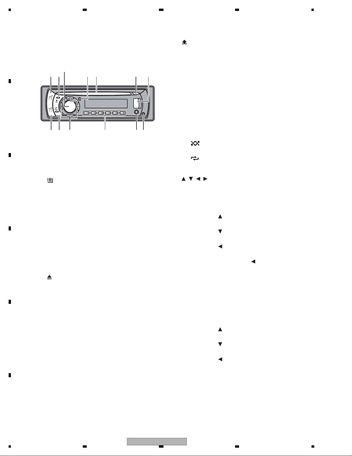
2.3 PANEL FACILITIES
What ’s what
Head unit
d c 98
1 2 5 6 74
3
b a
1 SRC/OFF button
This unit is turned on by selecting a source.
Press to cycle through all the available
sources.
2
/LIST button
Press to display the disc title list, track title
list, folder list or file list.
3 MULTI-CONTROL
Turn to increase or decrease the volume.
Also used for controlling functions.
4 CLOCK button
Press to change to the clock display.
5 Disc loading slot
Insert a disc to play.
6
(eject) button
Press to eject a disc.
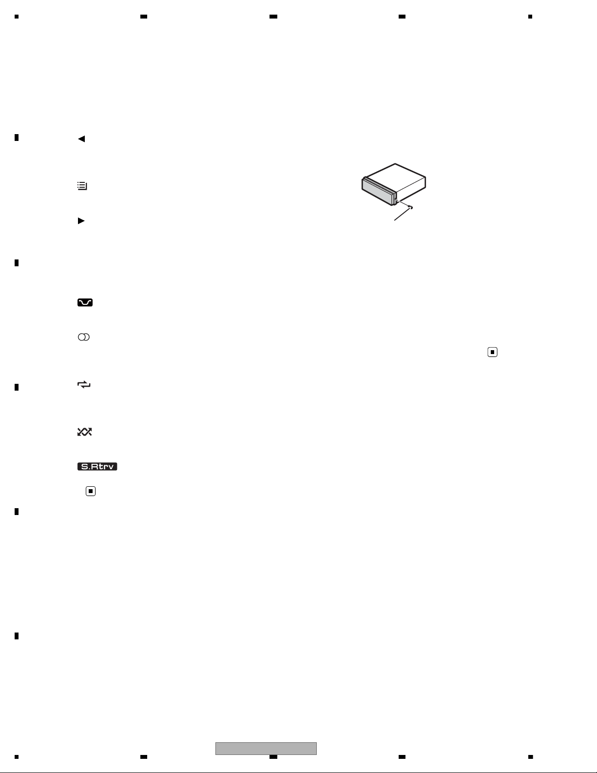
7 USB port
Use to connect a USB audio player/USB
memory.
• When connecting, open up the USB connector lid.
• Use a USB cable to connect the USB
audio player/USB memory to the USB
port. Since the USB audio player/USB
memory is projected forward from the
unit, it is dangerous to connect directly.
Pioneer CD-U50E USB cable is also available. For details, consult your dealer.
8
(detach) button
Press to remove the front panel from the
head unit.
9 AUX input jack (3.5 mm stereo jack)
Use to connect an auxiliary device.
a 1 to 6 buttons
Press for preset tuning. Also used for controlling functions.
• 1/S.Rtrvcan be used to control S.RTRV
(sound retriever).
• 2/PAUSEcan be used to control PAUSE
(pause).
• 5/
can be used to control RANDOM
(random).
• 6/
can be used to control REPEAT (re-
peat).
b
/ / / buttons
Press to perform manual seek tuning, fast
forward, reverse and track search controls.
Also used for controlling functions.
• When operating menus
— Pressing
is the same function as
turning MULTI-CONTROL right.
— Pressing
is the same function as
turning MULTI-CONTROL left.
— Pressing
is the same function as
pressing DISP/BACK/SCRL.
— Pressing and holding
is the same
function as pressing and holding
DISP/BACK/SCRL .
— Pressing d is the same function as
pressing MULTI-CONTROL.
— Pressing and holding d is the same
function as pressing and holding
MULTI-CONTROL .
• When operating lists
— Pressing
is the same function as
turning MULTI-CONTROL left.
— Pressing
is the same function as
turning MULTI-CONTROL right.
— Pressing
is the same function as
pressing DISP/BACK/SCRL .
10
DEH-20UB/XS/UC
5678
56
7
8
C
D
F
A
B
E
6
8
4
— Pressing and holding is the same
function as pressing and holding
DISP/BACK/SCRL .
— Pressing d is the same function as
pressing MULTI-CONTROL .
— Pressing and holding
is the same
function as pressing and holding
MULTI-CONTROL .
c DISP/BACK/SCRL button
Press to select different displays.
Press and hold to scroll through the text information.
Press to return to the previous display when
operating the menu.
Press and hold to return to the main menu
when operating the menu.
d BAND/ESC button
Press to select among three FM bands and
one AM band.
Press to return to the ordinary display when
operating the menu.
g AUDIO button
Press to select an audio function.
h
button
Press to turn pause on or off.
i FUNCTION button
Press to select functions.
Press and hold to recall the initial setting
menu when the sources are off.
j LIST/ENTER button
Press to display the disc title list, track
title list, folder list or file list depending
on the source.
While in the operating menu, press to control functions.
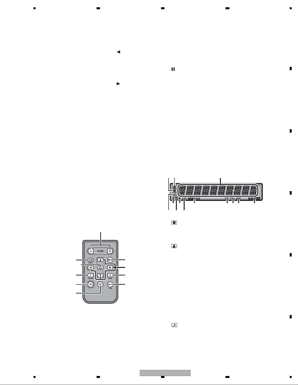
Display indication
12
3
Remote control
Operation is the same as when using the buttons on the head unit.
e
d
j
f
b
gi
1
c
h
e VOLUME buttons
Press to increase or decrease the volume.
f MUTE button
Press to turn off the sound. To turn on the
sound, press again.
5
7
9 abc d
1 (disc) indicator
Appears when the disc (album) name is displayed on the main display section.
2
(artist) indicator
Appears when the disc (track) artist name is
displayed on the main display section.
3 Main display section
Displays band, frequency, elapsed playback
time and other settings.
• Tuner
Band and frequency are displayed.
• Built-in CD player and USB
Elapsed playback time and literal information are displayed.
4
(song) indicator
Appears when the track (song) name is displayed on the main display section.
DEH-20UB/XS/UC
11
1234
1234
C
D
F
A
B
E
Also, appears when a playable audio file is
selected while operating the list.
5
indicator
Appears when an upper tier of folder or
menu exists.
6
(folder) indicator
Appears when operating list function.
7
indicator
Appears when a lower tier of folder or menu
exists.
8 LOC indicator
Appears when local seek tuning is on.
9
LOUD (loudness) indicator
Appears when loudness is on.
a
(stereo) indicator
Appears when the selected frequency is
being broadcast in stereo.
b
(repeat) indicator
Shows when track repeat is turned on.
Also, shows when folder repeat is on.
c
(random) indicator
Shows when random play is on.
d
(Sound Retriever) indicator
Appears when Sound Retriever function is
on.
Fastening the front panel
If you do not plan to detach the front panel,
the front panel can be fastened with supplied
screw.
Screw
Screw Parts No.
DEH-20UB/XS/UC BPZ20P060FTC
DEH-2150UBG/XS/ES
DEH-2150UB/XS/ES XXX7020
DEH-2150UB/XU/CN5 (Service)
12
DEH-20UB/XS/UC
5678
56
7
8
C
D
F
A
B
E
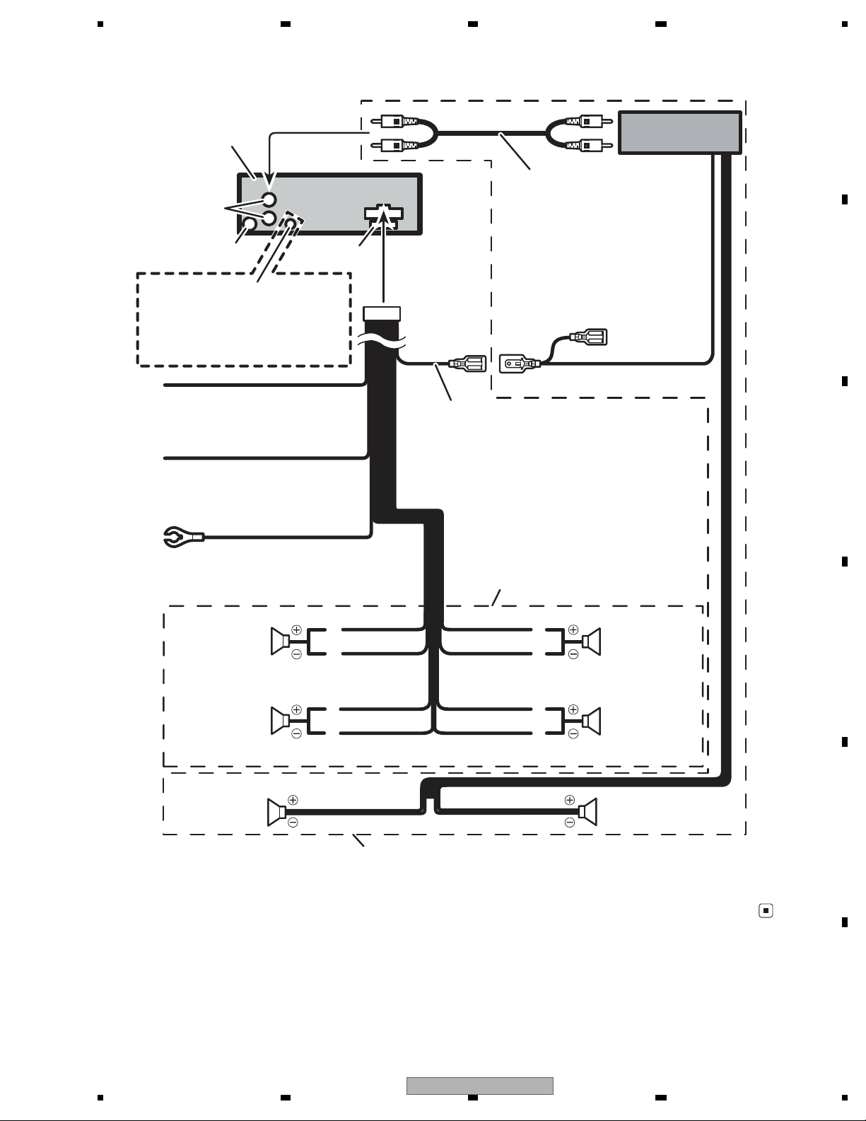
Connect with RCA cables
(sold separately)
Rear output
This product
Antenna jack
Fuse (10 A)
Blue/white
Connect to system control terminal of the
power amp or auto-antenna relay control
terminal (max. 300 mA 12 V DC).
Yellow
Connect to the constant 12 V
supply terminal.
Red
Connect to terminal controlled
by ignition switch (12 V DC).
Black (chassis ground)
Connect to a clean, paint-free
metal location.
Power amp
(sold separately)
System remote control
Left Right
Perform these connections when using
the optional amplifier.
rekaepsraeRrekaepsraeR
White/black
Violet/black
Violet
With a 2 speaker system, do not connect
anything to the speaker leads that are not
connected to speakers.
rekaepstnorFrekaepstnorF
White
Gray/black
Gray
Green/black
Green
rekaepsraeRrekaepsraeR
W
ired remote input
Hard-wired remote control adaptor
can be connected (sold separately).
DEH-2150UBG/XS/ES
DEH-2150UB/XS/ES
DEH-2150UB/XU/CN5
2.4 CONNECTION DIAGRAM
DEH-20UB/XS/UC
13
1234
1234
C
D
F
A
B
E
3. BASIC ITEMS FOR SERVICE
demrifnocebotmetIserudecorP.oN
1 Confirm whether the customer complain has
been solved.
If the customer complain occurs with the
specific media, use it for the operation check.
The customer complain must not be
reappeared.
Display, audio and operations must be
normal.
2 CD Play back a CD.
(Track search)
No malfunction on display, audio and
operation.
3 FM/AM tuner Check FM/AM tuner action.
(Seek, Preset)
Switch band to check both FM and AM.
Display, audio and operations must be
normal.
4 Check whether no disc is inside the product. The media used for the operating check must
be ejected.
retfaecnaraeppastinotridrosehctarcsoNkcehcecnaraeppA5
receiving it for service.
Item to be checked regarding audio
3.1 CHECK POINTS AFTER SERVICING
To keep the product quality after servicing, please confirm following check points.
See the table below for the items to be checked regarding audio:
Distortion
Noise
Volume too low
Volume too high
Volume fluctuating
Sound interrupted
14
DEH-20UB/XS/UC
5678
56
7
8
C
D
F
A
B
E
3.2 PCB LOCATIONS
CD Core Unit (S10.5COMP2-USB-C3)
C
Tuner Amp Unit
A
Keyboard Unit
B
A:DEH-20UB/XS/UC
B:DEH-2150UB/XS/ES
C:DEH-2150UBG/XS/ES
D:DEH-2150UB/XU/CN5
Unit Number : YWM5319(A)
Unit Number : YWM5322(B)
Unit Number : YWM5318(C)
Unit Number : YWM5400(D)
Unit Name : Tuner Amp Unit
Unit Number :
Unit Name : Keyboard Unit
Unit Number : CWX3679
Unit Name : CD Core Unit(S10.5COMP2-USB-C3)
DEH-20UB/XS/UC
15
1234
1234
C
D
F
A
B
E
3.3 JIGS LIST
- Jigs List
Name
Test Disc
L.P.F.
Jig No.
TCD-782
Remarks
Checking the grating
Checking the grating (Two pieces)
Name
Jig
- Grease List
Name
Grease
Grease
Grease No.
GEM1024
GEM1045
Remarks
CD Mechanism Module
CD Mechanism Module
e
Before shipping out the product, be sure to clean the
following portions by using the prescribed cleaning
tools:
Portions to be cleaned Cleaning tools
CD pickup lenses Cleaning liquid : GEM1004
Cleaning paper : GED-008
m
3.4 CLEANING
No.
rease No.
emarks
emarks
16
DEH-20UB/XS/UC

5678
56
7
8
C
D
F
A
B
E
DEH-20UB/XS/UC
17
1234
1234
C
D
F
A
B
E
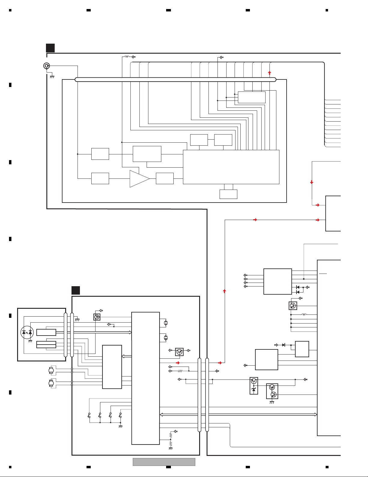
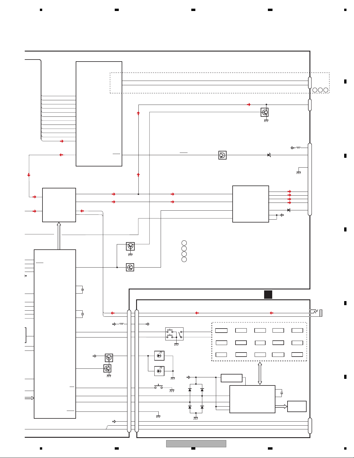
4. BLOCK DIAGRAM
PICKUP UNIT
(P10.5)(SERVICE)
CD CORE UNIT(S10.5COMP2-USB-C3)
C
BRST,BRXEN,BSRQ
CN701
Q101
M
LD
MD
S903
DSCSNS
SPINDLE
MOTOR
M
LOADING/CARRIAGE
MOTOR
LD-
MD
15
5
HOLOGRAM
UNIT
IC301
BA5839FP
IC201
PE5666A
RF AMP, CD DECODER, MP3&WMA DECODER
DIGITAL SERVO/DATA•PROCESSOR
CPU, USB HOST CONTROLLER
ACTUATOR/
MOTOR DRIVER
2
VD
VD
13
LOUT
9
CN101
16
SOP
15
SOM
18
LCOP
17
LCOM
21
CLCONT
55
LOUT
9
CONT
TD,FD
AC,BD,E,F
SD,MD
S901
HOME
S904
12EJ
S905
8EJ
LD+
14
141
LD
142
PD
12EJ
CONT
CLCONT
HOME
8
9
20
41
VDD
1
VDD2
BDATA,BSCK
VDD
15
5
FOCUS ACT.
TRACKING ACT.
FOP
TOP
2
1
TOP
FOP
11
FOP
14
TOP
2
1
14
8EJ
7
DSCSNS
10
16
/RESET
8
/RESET
88
VREF
REFO
133
REFOUT
33
FOM
FOM
12
FOM
44
TOM
TOM
13
TOM
22
LOEJ
LOEJ
28
52
50
X201
XTAL
/XTAL
16.93MHz
VDSENS
11
VD
16
17
DP
DM
4
5
DM
DP
2
1
X205
48MHz
USBXTAL
/USBXTAL
VDD2
Q102
39
/PUEN
VCC
VDD2
IN2_L
IN1_L
2
IC
PM
ELECTRON
SOURCE
TUNL
1
CN401
1
2
CN651
TUNER AMP UNIT
VCK, VDT, VST
LOUT
A
SYS+B
ANTENNA
IFA
IFB
7
VDD3V
11
SWVDD3V
SW5V
6
5
BSENS
SYSPW
PWROFF
2
1
36
47
15
SWVDD
4
1
BRST,BRXEN,BSRQ,BDATA,BSCK
CDRST
12
4
3
RESET
16
FM/AM TUNER UNIT
ANT
SL-IN
REFA
REFB
LDET
SWVDD3V
DI
CK
CE1
DO
CE2
SLOUT
SL-IN
IFA
IFB
REFA
REFB
LDET
DI
CK
CE1
DO
CE2
SLOUT
CD-Lch
3
REGULATOR IC
IC911
BA49181-V12
B.UP
10
9
VDD3V
SYS+B
SWVDD
VDD
SW5V
SYS+B
BESNS
SW5VCONT
+B
IC501
BD9007F
USB5V
IC251
BD6538G
PVin
Vin
SW
EN
VIN
EN
FLG
+B.UP
VDDCONT
SYSPW
8
7
USB5V
VOUT
5
IC601(
PN502
SYSTEM
COMPU
DREG
85
SYNC
USBCTL
FLG
25
5
2
8
1
28
1
3
27
4
SWVDD3V
Q601
PLL_VDD
DVDD3
M-REGC
55
9
57
DVDD2
94
DVDD4
121
B.UP
5
Q991
18
19
Q992
VDCONT
126
CD VD
VD
B.UP
USBZ
USBF
ATT
ATT
TANK
ATT RF
LFP
LFPVCO
CF
IC1
MIX / IF / PLL
IC2
EEPROM
1 2 3 4 5 6 7 8 9 10 12 13 14 15 16 17 18 19 2011
ANT
VCC
SLIN
IFOUTA
IFOUTB
DGND
REFINA
REFINB
LDET
VDD
DI
CK
CE1
DO
CE2
SLOUT
RFGND1
RFGND2
RFGND3
RFGND4
VDD
4.1 BLOCK DIAGRAM
18
DEH-20UB/XS/UC
5678
56
7
8
C
D
F
A
B
E
IN2_L
IN1_L
2
IC151
PML014A
ELECTRONIC VOLUME/
SOURCE SELECTOR
TUNL
1
7
Rear_L
B.UP
35
44
MUTE
21
23
3
5
FL−
VCC
VCC
FL+
RL−
RL+
FL−
FL+
RL−
RL+
BREM
ACC
GND
22
IC601(1/2)
PN5025B
AMP
IC301
PAL007C
Q931
MUTE
CN831
VCK, VDT, VST
Q201(1/2)
Q201(2/2)
B.UP
Q821
SYSTEM MICRO
COMPUTER
ASENSE
3
9
11
12
10
1
2
CN911
15
4
19
16
18
SOURCE
ROT1
ILM+B
DPDT
KYDT
SRC
33
111
ILMPW
2
DPDT
23
KYDT
24
CN351
RLIn
12
ROT1
17
ROT0
110
ROT0
Q822
20
DSENSE
VBUS
DSENS
34
13
12
D-
D+
ASENS
6
Front_L
FLIn
14
XOUT
XIN
82
X601
74.1MHz
81
BU_X1
BU_X2
52
X602
4.7186MHz
51
Q351
MUTE
20
6
25
B.REM
ASENS
RL
6
BSENS
SYSPW
PWROFF
36
47
15
SWVDD
1
CDRST
16
SL
62
SL-IN
IF_INA
77
IFA
IF_INB
78
IFB
FREFA
96
REFA
FREFB
97
REFB
LOCK
99
LDET
TUNDO
100
DI
TUNCK
101
CK
TUNDI
102
CE1
CE2
CE
103
DO
SL
109
CE2
136
SLOUT
KEYAD
KEYD
CN871
2
2
3
KEYAD
142
130
KEYD
B.UP
WIRED
REMOTE
RCA OUT
POWER
CONNECTOR
L_OUT
59
CD-Lch
B.UP
IC601(2/2)
PN5025B
SYSTEM MICRO
COMPUTER
4
STBY
B.UP
3
SW5V
14
USB5V
USBZ
USBF
AUX-G
6
AUX-L
7
AUX-L
4
AUX-G
5
IN4+_L
IN4-_L
ILMPW
DREG
85
SYNC
USBCTL
FLG
25
5
28
27
PLL_VDD
DVDD3
M-REGC
55
9
57
DVDD2
94
DVDD4
121
:DEH-20UB/XS/UC
:DEH-2150UB/XS/ES
:DEH-2150UBG/XS/ES
:DEH-2150UB/XU/CN5
MUTE
B.UP
VDCONT
126
A
B
C
D
B
C
D
DSEN
SOURCE
DPDT
KYDT
D-
D+
VBUS
D-
D+
VBUS
LCD DRIVER/
KEY CONTROLLER
IC1801
PD6340A
KEY DATA
KDT0-3
KST0-4
LCD1801
CN1801
CN1802
CN1803
FRONT
AUX
USB
KEYBOARD UNIT
18
14
18
20
DPDT
KYDT
B
12
13
SW5V
SW5V
19
X0
X1
22
X1801
5.00MHz
23
KEY MATRIX
S1829
S1830
S1831
S1832
CLOCK
S1827
S1828
S1811
S1833
SOURCE
S1802
6
S1815
S1813
DISP/BACK
S1819
UP
S1825
S1826
RIGH
S1817
S1823
S1803
S1834
S1805
S1807
10
56
VLCD
VDD
4
1
3
2
20
17
16
1
2
4
5
3
3
15
17
1
3
IC1802
GP1UXC14RK
REMOTE CONTROL
SENSOR
REM
S1801
CD EJECT
S1809
1
3
2
4
5
LIST
DOWN
LEFT
AUX L
7
AUX G
AUX L
AUX R
AUX G
ROT1
ROT0
KST1
KDT2
6
BAND/ESC
2
3
1
ILM+B
ILLUMI
D1824-D1832
D1834-D1840
LCDBK
D1823
DEH-20UB/XS/UC
19
1234
1234
C
D
F
A
B
E
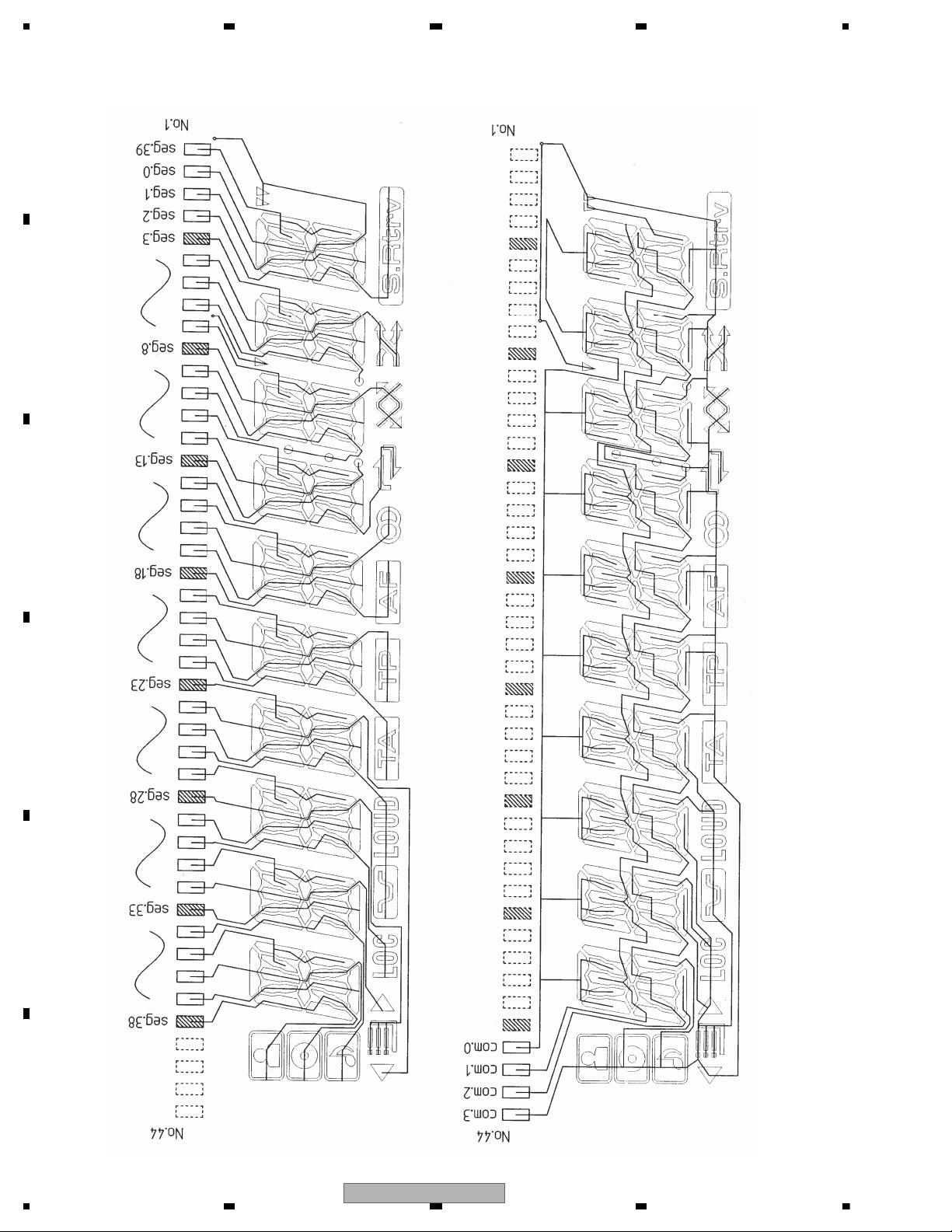
SEGMENT
COMMON
LCD (CAW1970)
20
DEH-20UB/XS/UC
5678
56
7
8
C
D
F
A
B
E
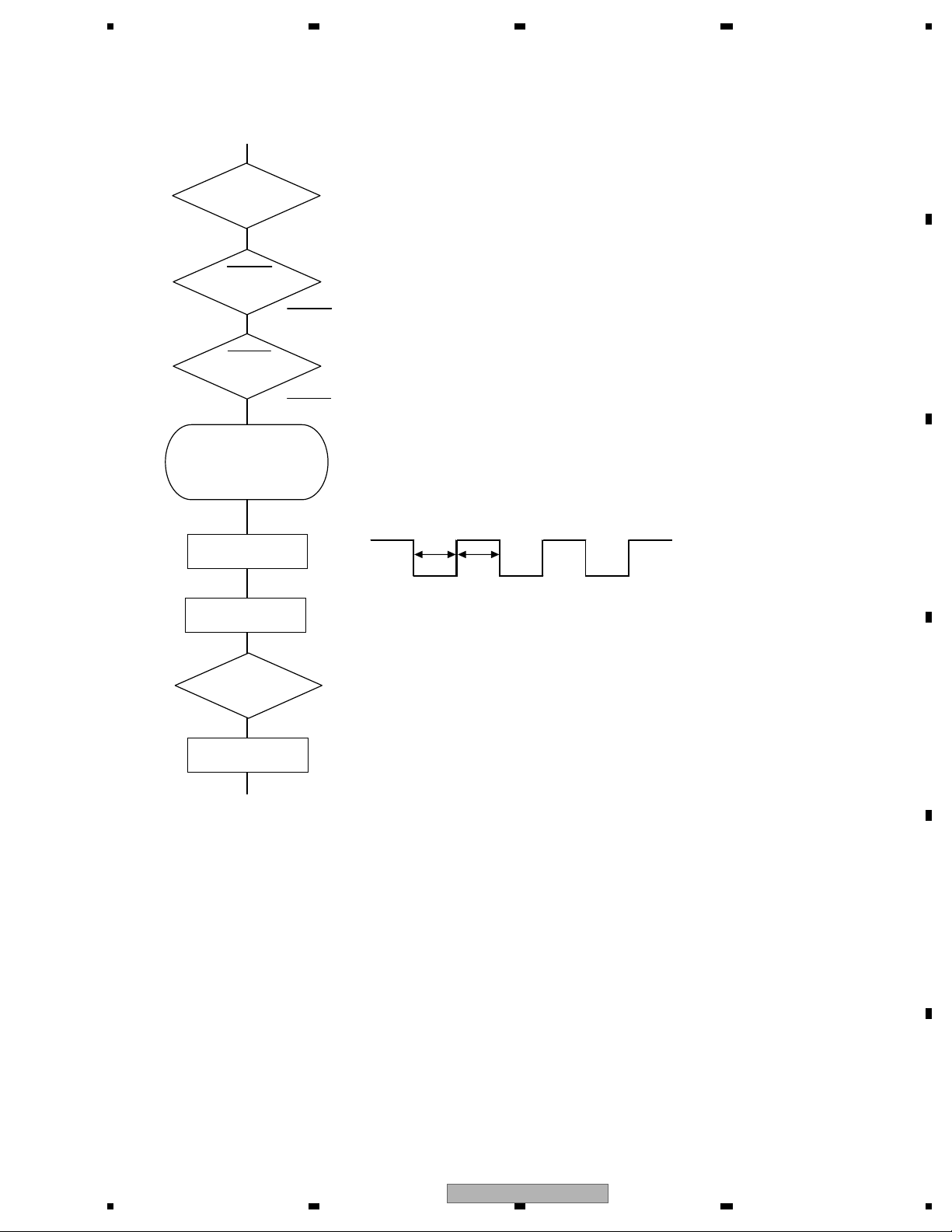
VDD = 3.3 V
Pin 8
BSENS
Pin 36
ASENS
Pin 35
BSENS = L
Starts
communication
with Grille
microcomputer.
SWVDD <- H
Pin 1
Source keys
operative
Source ON
SYSPW <- H
Pin 15
300 ms
300 ms
Completes power-on operation.
(After that, proceed to each source operation)
In case of the above signal, the communication
with Grille microcomputer may fail.
If the time interval is not 300 msec, the oscillator
may be defective.
Power ON
ASENS = L
5. DIAGNOSIS
5.1 OPERATIONAL FLOWCHART
DEH-20UB/XS/UC
21
1234
1234
C
D
F
A
B
E
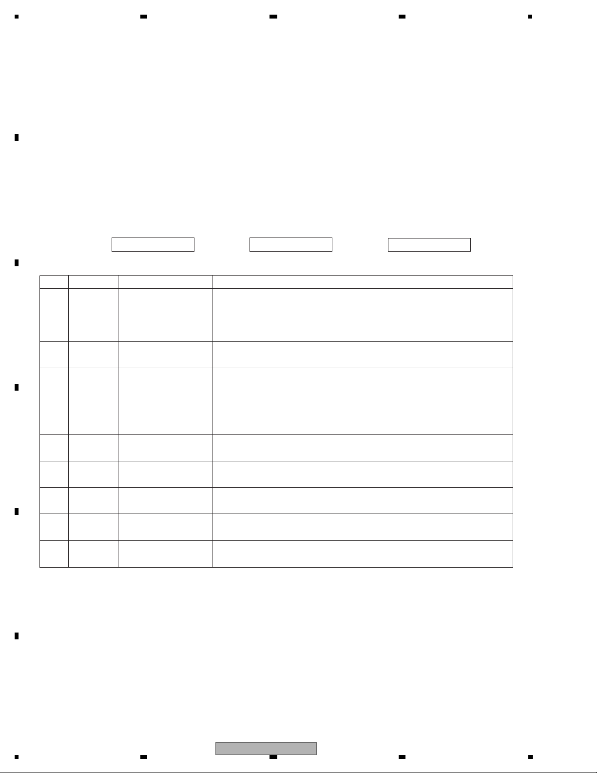
5.2 ERROR CODE LIST
- Error Messages
If a CD is not operative or stopped during operation due to an error, the error mode is turned on and cause(s) of
the error is indicated with a corresponding number. This arrangement is intended at reducing nonsense calls from
the users and also for facilitating trouble analysis and repair work in servicing.
(1) Basic Indication Method
1) When SERRORM is selected for the CSMOD (CD mode area for the system), error codes are written to DMIN
(minutes display area) and DSEC (seconds display area). The same data is written to DMIN and DSEC. DTNO
remains in blank as before.
2) Head unit display examples
Depending on display capability of LCD used, display will vary as shown below. xx contains the error number.
8-digit display 6-digit display 4-digit display
ERROR-xx ERR-xx E-xx
(2) Error Code List
Code Class Displayed error code Description of the code and potential cause(s)
10 Electricity Carriage Home NG CRG can't be moved to inner diameter.
SERVO LSI Com- CRG can't be moved from inner diameter.
munication Error -> Failure on home switch or CRG move mechanism.
Communication error between microcomputer and SERVO LSI.
11 Electricity Focus Servo NG Focusing not available.
-> Stains on rear side of disc or excessive vibrations on REWRITABLE.
12 Electricity Spindle Lock NG Spindle not locked. Sub-code is strange (not readable).
Subcode NG -> Failure on spindle, stains or damages on disc, or excessive vibrations.
A disc not containing CD-R data is found.
Turned over disc are found, though rarely.
CD signal error.
17 Electricity Setup NG AGC protection doesn't work. Focus can be easily lost.
-> Damages or stains on disc, or excessive vibrations on REWRITABLE.
30 Electricity Search Time Out Failed to reach target address.
-> CRG tracking error or damages on disc.
44 Electricity ALL Skip Skip setting for all track.
(CD-R/RW)
50
Mechanism
CD On Mech Error Mechanical error during CD ON.
-> Defective loading motor, mechanical lock and mechanical sensor.
A0 System Power Supply NG Power (VD) is ground faulted.
-> Failure on SW transistor or power supply (failure on connector).
Remarks: Mechanical errors are not displayed (because a CD is turned off in these errors).
Unreadable TOC does not constitute an error. An intended operation continues in this case.
Upper digits of an error code are subdivided as shown below:
1x: Setup relevant errors, 3x: Search relevant errors, Ax: Other errors.
22
DEH-20UB/XS/UC
 Loading...