

Sony DCR-TRV820E Service Manual
DCR-TRV820E
RMT-814
SERVICE MANUAL
Level 1
B700 MECHANISM
Video camera
recorder
System
Video recording system
2 rotary heads
Helical scaning system
Audio recording system
Rotary heads, PCM system
Quantization: 12 bits (Fs 32 kHz,
stereo 1, stereo 2), 16 bits
(Fs 48 kHz, stereo)
Video signal
PAL colour, CCIR standards
Recommended cassette
Hi8/Digital8 video cassette
Recording/Playback time (using
120 min. Hi8 video cassette)
SP mode: 1 hour
LP mode: 1 hour and 30 minutes
Fastforward/rewind time (using
120 min. Hi8 video cassette)
Approx. 5 min.
Viewfinder
Electric Viewfinder (colour)
Image device
1/4 type CCD (Change Coupled
Device)
Approx. 800,000 pixels
(Effective: Approx. 400,000 pixels)
Lens
Combined power zoom lens
Filter diameter 37 mm (1 1/2 in.)
25× (Optical)
100× (Digital)
Ver. 1.0 2000. 04
TM
Focal length
3.7 - 92.5 mm (5/32 - 3 3/4 in.)
When converted to a 35 mm still camera
48 - 1200 mm (1 15/16 - 47 1/4 in.)
Colour temperature
Auto
Minimum illumination
3 lux (F 1.6)
0 lux (in the NightShot mode)*
* Objects unable to be seen due to the
dark can be shot with infrared
lighting.
Input/output
connectors
S video input/output
4-pin mini DIN
Luminance signal: 1 Vp-p,
75 ohms, unbalanced
Chrominance signal: 0.3 Vp-p,
75 ohms, unbalanced
Audio/Video output
AV MINIJACK, 1 Vp-p, 75 ohms,
unbalanced, sync negative
327 mV, (at output impedance more than
47 kilohms)
Output impedance with less than 2.2
kilohms/Stereo minijack (ø 3.5 mm)
DV input/output
4-pin connector
Headphone jack
Stereo minijack (ø 3.5 mm)
LANC
/DIGITAL I/O jack
Stereo mini-minijack (ø 2.5 mm)
Transfer rate: Max 115.2 Kbps
RS-232C based
SPECIFICATIONS
MIC jack
Stereo minijack (ø 3.5 mm)
LCD screen
Picture
4.0 type
80.6 × 60.5 mm (3 1/4 × 2 1/2 in.)
Total dot number
123,200 (560 × 220)
Printer
Print method
Variable dot thermal transfer
Print resolution
254 dpi
Number of printed dots
640 × 480 (paper feed direction)
Print speed
2.54 mm (1/8 in.)/second
Size of print paper
91 × 55 mm
(3 5/8 × 2 1/4 in.)
Print area size
64 × 48 mm
(2 5/8 × 1 15/16 in.)
Number of prints per print
cartridge roll
20
Power Consumption
8 W
AEP Model
UK Model
General
power requirements
7.2 V (battery pack)
8.4 V (AC power adaptor)
Average power consumption
(When using the battery pack)
During camera recording using
LCD
4.4 W
Viewfinder
3.1 W
Operating temperature
0 °C to 40 °C (32 °F to 104 °F)
Storage temperature
–20 °C to +60 °C (–4 °F to +140 °F)
Dimensions (approx.)
112 × 121 × 218 mm
(4 1/2 × 4 7/8 × 8 5/8 in.) (w/h/d)
Mass (approx.)
1.3 kg (2 lb 13 oz)
excluding the battery pack, lithium battery,
cassette and shoulder strap
1.4 kg (3 lb 1 oz)
including the battery pack NP-F330,
lithium battery CR2025, 90 min. Hi8
cassette, and shoulder strap
– Continued on next page –
DIGITAL VIDEO CASSETTE RECORDER

AC power adaptor
Power requirements
100 - 240 V AC, 50/60 Hz
Power consumption
23 W
Output voltage
DC OUT: 8.4 V, 1.5 A in the
operating mode
Operating temperature
0 °C to 40 °C (32 °F to 104 °F)
Storage temperature
–20 °C to +60 °C (–4 °F to +140 °F)
Dimensions (approx.)
125 × 39 × 62 mm
(5 × 1 9/16 × 2 1/2 in.) (w/h/d)
excluding projecting parts
Mass (approx.)
280 g (9.8 oz)
excluding power cord
Battery Pack
Output voltage
DC 7.2 V
Capacity
5.0 Wh
Dimensions (approx.)
38 × 21 × 71 mm
(1 9 /16 × 1 3/16 × 2 7/8 in.) (w/h/d)
Mass (approx.)
95 g (3.4 oz)
Type
Lithium ion
“Memory Stick”
Memory
Flash memory
4 MB: MSA-4A
Operating voltage
2.7 - 3.6 V
Power consumption
Approx. 45 mA in the operating mode
Approx. 130 µA in the standby mode
Dimensions (approx.)
50 × 2.8 × 21.5 mm
(2 × 1/8 × 7/8 in.) (w/h/d)
Mass (approx.)
4 g (0.14 oz)
Design and specifications are subject to
change without notice.
SAFETY-RELATED COMPONENT WARNING!!
COMPONENTS IDENTIFIED BY MARK 0 OR DOTTED
LINE WITH MARK 0 ON THE SCHEMATIC DIAGRAMS
AND IN THE PARTS LIST ARE CRITICAL TO SAFE
OPERATION. REPLACE THESE COMPONENTS WITH
SONY PARTS WHOSE PART NUMBERS APPEAR AS
SHOWN IN THIS MANUAL OR IN SUPPLEMENTS PUBLISHED BY SONY.
SAFETY CHECK-OUT
After correcting the original service problem, perform the following
safety checks before releasing the set to the customer.
1. Check the area of your repair for unsoldered or poorly-soldered connections. Check the entire board surface for solder
splashes and bridges.
2. Check the interboard wiring to ensure that no wires are
“pinched” or contact high-wattage resistors.
3. Look for unauthorized replacement parts, particularly transistors, that were installed during a previous repair. Point them
out to the customer and recommend their replacement.
4. Look for parts which, though functioning, show obvious signs
of deterioration. Point them out to the customer and recommend their replacement.
5. Check the B+ voltage to see it is at the values specified.
6. Flexible Circuit Board Repairing
• Keep the temperature of the soldering iron around 270 ˚C
during repairing.
• Do not touch the soldering iron on the same conductor of
the circuit board (within 3 times).
• Be careful not to apply force on the conductor when soldering or unsoldering.
– 2 –

TABLE OF CONTENTS
Section Title Page Section Title Page
SERVICE NOTE
1. Power Supply During Repairs....................................... 4
2. To Take Out a Cassette When Not Eject
(Force Eject) .................................................................. 4
3. Note for Repair .............................................................. 5
SELF-DIAGNOSIS FUNCTION
1. Self-diagnosis Function................................................. 6
2. Self-diagnosis Display................................................... 6
3. Service Mode Display ................................................... 6
3-1. Display Method.............................................................. 6
3-2. Switching of Backup No. ............................................... 6
3-3. End of Display ............................................................... 6
4. Self-diagnosis Code Table ............................................ 7
1. MAIN PARTS
1. Ornamental Parts .......................................................... 9
2. DISASSEMBLY
2-1. LCD Assembly ............................................................... 12
2-2. PD-118 Board ................................................................ 12
2-3. LCD Module................................................................... 12
2-4. VF-141 Board, VF Lens Assembly................................ 12
2-5. Front Panel Assembly ................................................... 13
2-6. Cassette Lid Assembly.................................................. 13
2-7. Cabinet (L) Assembly .................................................... 13
2-8. Cabinet (R) Assembly ................................................... 13
2-9. CF-72 Board .................................................................. 14
2-10. PC-78 Board .................................................................. 14
2-11. Battery Panel Assembly ................................................ 14
2-12. FP-162 Flexible Board .................................................. 14
2-13. PR-33 Board .................................................................. 15
2-14. Printer Unit .................................................................... 1 5
2-15. Lens Block ..................................................................... 15
2-16. SE-114 Board ................................................................ 15
2-17. Control Switch Block (FK-10000).................................. 1 6
2-18. FU-141 Board ................................................................ 16
2-19. VC-235 Board ................................................................ 16
3. REPAIR PARTS LIST
3-1. Exploded Views ............................................................. 17
3-1-1. Front Panel Section ................................................. 1 7
3-1-2. Cabinet (R) Section.................................................. 18
3-1-3. LCD Assembly Section ............................................ 19
3-1-4. EVF Block Section ................................................... 20
3-1-5. Cabinet (L) Section .................................................. 21
3-1-6. Battery Panel Block Section .................................... 22
3-1-7. Lens Block Section................................................... 23
3-1-8. LCD EVF Block Section ........................................... 24
4. GENERAL
Checking Supplied Accessories............................................. 25
Quick Start Guide .................................................................... 25
Using This Manual................................................................... 26
Step 1 Preparing the Power Supply........................................ 26
Step 2 Inserting a Cassette..................................................... 28
Recording a Picture................................................................. 2 9
Checking the Recording
– END SEARCH/EDIT SEARCH/Rec Review ........................ 31
Playing Back a Tape ................................................................ 32
Viewing the Recording on TV.................................................. 33
Recording a Still Image on a Tape
– Tape Photo Recording .......................................................... 34
Using the Wide Mode .............................................................. 35
Using the Fader Function........................................................ 3 5
Using Special Effects
– Picture Effect ........................................................................ 36
Using Special Effects
– Digital Effect ......................................................................... 36
Using the PROGRAM AE Function......................................... 37
Adjusting the Exposure Manually............................................ 37
Focusing Manually .................................................................. 38
Superimposing a Title.............................................................. 38
Making Y our Own Titles........................................................... 39
Inserting a Scene .................................................................... 39
Playing Back a Tape with Picture Effects................................ 39
Playing Back a Tape with Digital Effects ................................. 40
Enlarging Recorded Images
– PB ZOOM ............................................................................. 40
Quickly Locating a Scene Using the Zero Set
Memory Function..................................................................... 40
Searching a Recording by Date
– Date Search.......................................................................... 41
Searching for a Photo
– Photo Search/Photo Scan.................................................... 4 1
Dubbing a Tape ....................................................................... 42
Using with Analog Video Unit and PC
– Signal Convert Function ....................................................... 4 3
Recording Video or TV Programmes ...................................... 43
Inserting a Scene from a VCR
– Insert Editing......................................................................... 44
Changing the Menu Settings................................................... 45
Resetting the Date and Time ................................................... 47
Using “Memory Stick” – Introduction....................................... 47
Recording Still Images on “Memory Stick”
– Memory Photo Recording .................................................... 48
Superimposing a Still Image in the
“Memory Stick” on a moving Image
– MEMORY MIX ...................................................................... 50
Recording an Image from a Tape as a Still Image ................. 51
Copying Still Images from a Tape
– Photo Save ........................................................................... 51
Viewing a Still Image
– Memory Photo Playback ...................................................... 52
Copying the Image Recorded on
“Memory Stick” to Tapes.......................................................... 5 3
Enlarging Still Images Recorded on “Memory Stick”s
– Memory PB ZOOM ............................................................... 53
Playing Back Images in a Continuous Loop
– SLIDE SHOW ....................................................................... 54
Preventing Accidental Erasure
– Image Protection .................................................................. 54
Deleting Images....................................................................... 55
Writing a Print Mark
– PRINT MARK........................................................................ 55
Using the Printer
– Introduction........................................................................... 5 6
Making Prints
– Standard Print....................................................................... 58
Making Prints of Split Screens
– Split Printing ......................................................................... 60
Digital8 System, Recording and Playback.............................. 60
About i. LINK ........................................................................... 6 1
Changing the Lithium Battery in Your Camcorder .................. 61
Troubleshooting....................................................................... 62
Self-diagnosis Display ............................................................. 63
Warning Indicators and Messages.......................................... 63
Using Y our Camcorder Abroad ............................................... 64
Maintenance Information and Precautions ............................. 64
Identifying the Parts and Controls........................................... 65
– 3 –
SERVICE NOTE
1. POWER SUPPLY DURING REPAIRS
In this unit, about 10 seconds after power is supplied (8.4 V) to the
battery terminal using the service power cord (J-6082-223-A), the
power is shut off so that the unit cannot operate.
This following two methods are available to prevent this. Take
note of which to use during repairs.
Method 1.
Connect the servicing remote commander RM-95 (J-6082-053-B)
to the LANC jack, and set the remote commander switch to the
“ADJ” side.
Battery switch
Method 2.
Press the battery switch of the battery terminal using adhesive tape,
etc.
Method 3.
Battery terminal 3
Use the DC IN terminal. (Use the AC power adaptor.)
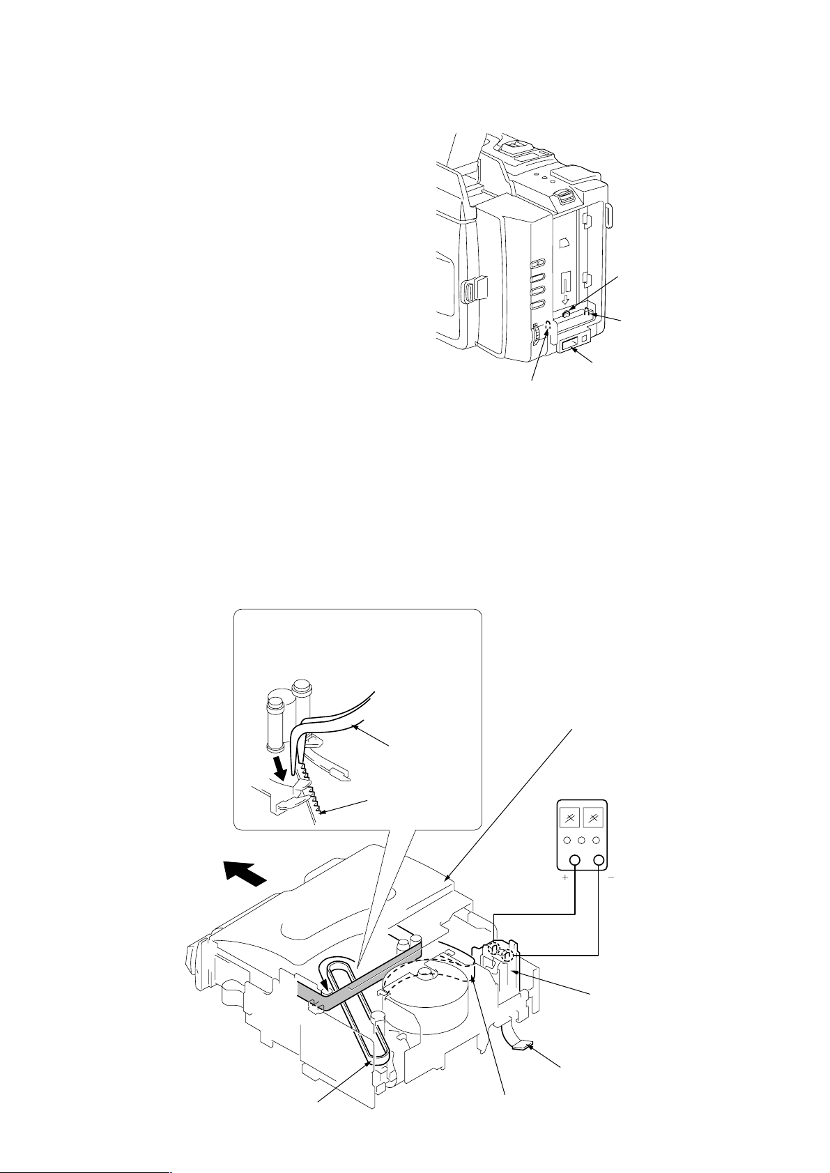
2. TO TAKE OUT A CASSETTE WHEN NOT EJECT (FORCE EJECT)
1 Refer to 2-5 to remove the front panel assembly.
2 Refer to 2-7 to remove the cabinet (L) assembly.
3 Refer to 2-8 to remove the cabinet (R) assembly.
4 Refer to 2-11 to remove the battery panel assembly.
5 Disconnect CN4401 of VC-235 board.
6 Add +5 V from the DC POWER SUPPLY and unload with a
pressing the cassette lid.
7 Pull the timing belt in the direction of the
arrow with a pincette while pressing
the cassette lid (be careful not to damage it)
to adjust the bending of a tape.
Battery terminal #
DC IN terminal
Press the cassette lid to rise
the cassette compartment
8 Let go your hold the cassette
lid and rise the cassette
compartment to take out a cassette.
Timing belt
Pincette
Timing belt
– 4 –
[DC power supply]
(+5V)
Loading motor
Disconnect CN4401
of VC-235 board.
Adjust the bending of a tape
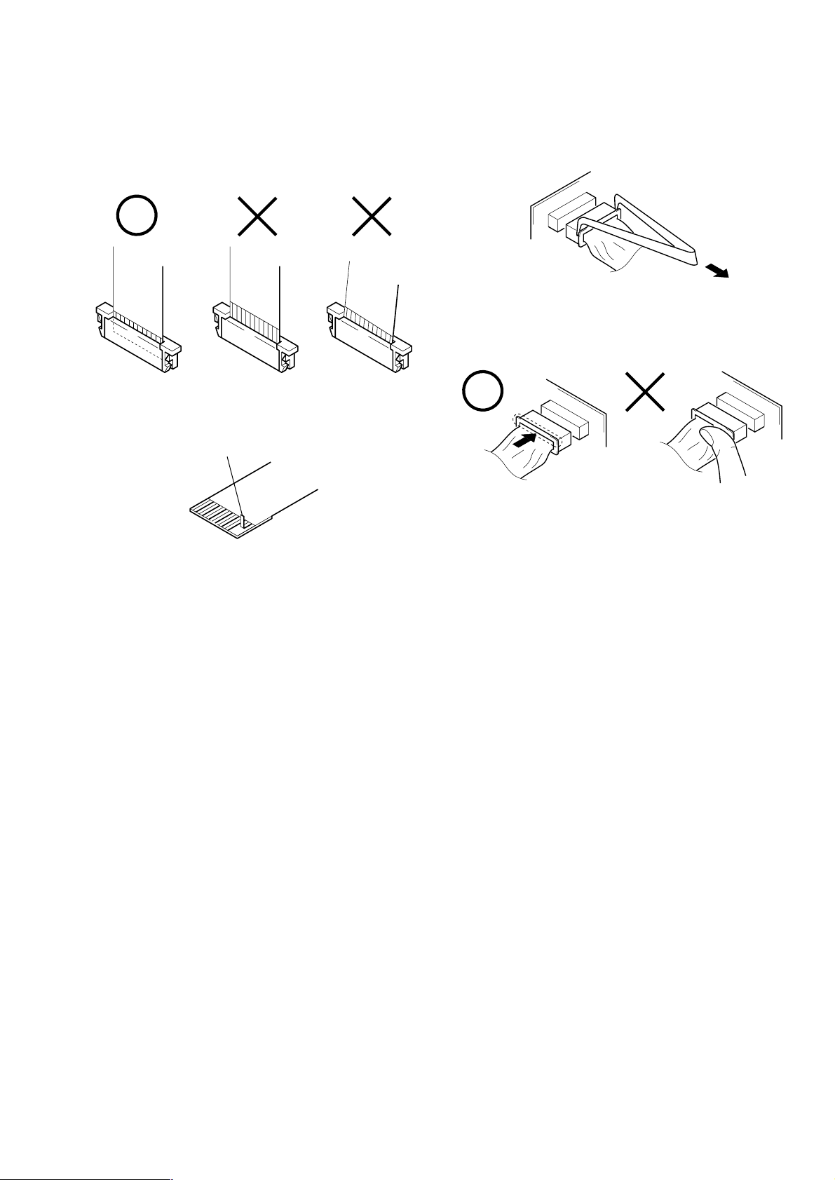
3. NOTE FOR REPAIR
When installing a connector, don’t press down at wire of connector.
It is possible that a wire is snapped.
Make sure that the flat cable and flexible board are not cracked of
bent at the terminal.
Do not insert the cable insufficiently nor crookedly.
Cut and remove the part of gilt
which comes off at the point.
(Be careful or some pieces of
gilt may be left inside)
When remove a connector, don’t pull at wire of connector.
It is possible that a wire is snapped.
– 5 –
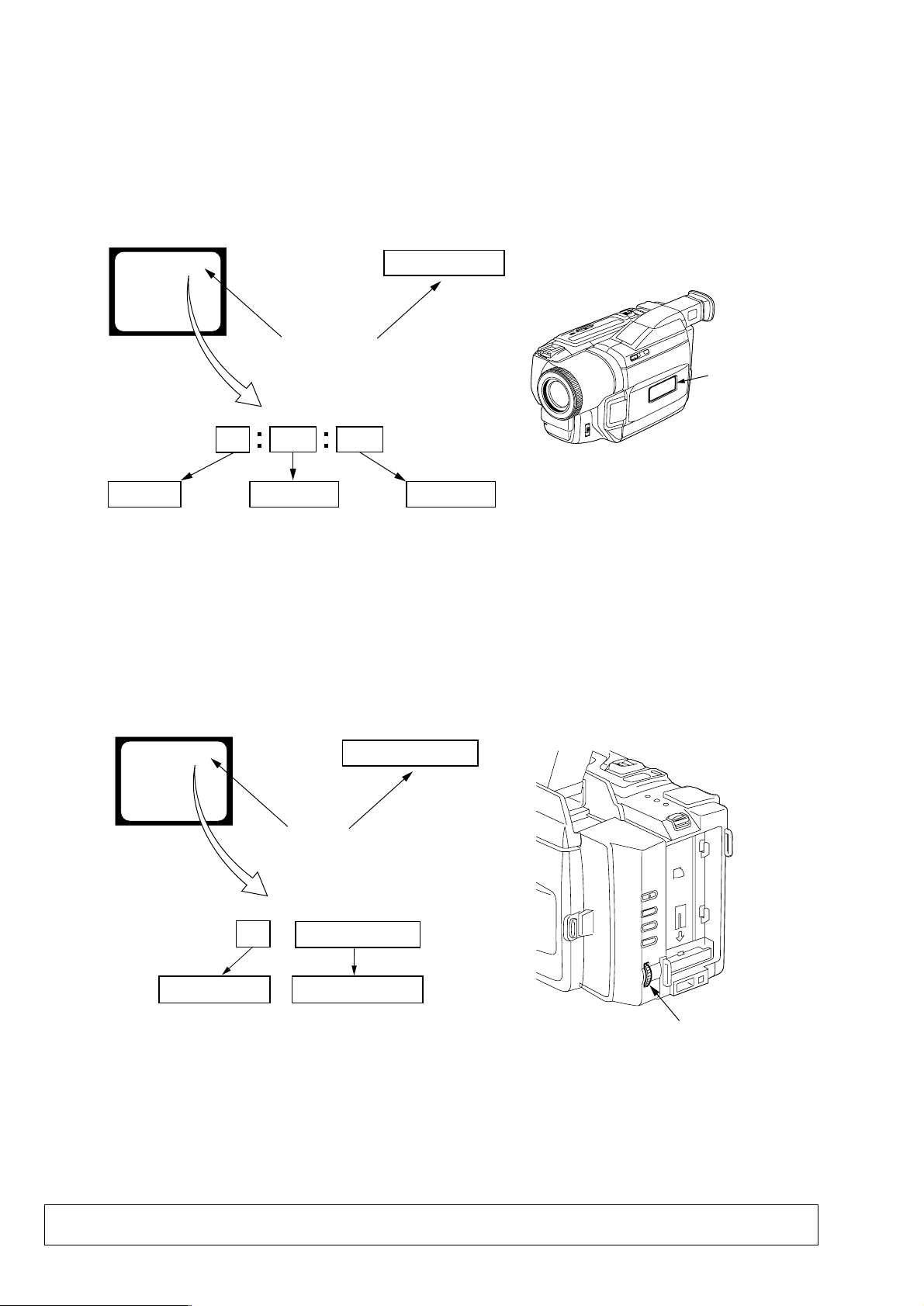
SELF-DIAGNOSIS FUNCTION
1. Self-diagnosis Function
When problems occur while the unit is operating, the self-diagnosis function starts working, and displays on the viewfinder or Display window what to do. This function consists of two display;
self-diagnosis display and service mode display.
Details of the self-diagnosis functions are provided in the Instruction manual.
Viewfinder Display window
C : 3 1 : 1 1
Repaired by:
C : Corrected by customer
H : Corrected by dealer
E : Corrected by service
engineer
Blinks at 3.2Hz
C
Indicates the appropriate
step to be taken.
E.g.
31 ....Reload the tape.
32 ....T u r n o n power again.
3 1
Block
1 1
C : 3 1 : 11
Refer to page 7 and 8.
Self-diagnosis Code Table.
2. Self-diagnosis Display
When problems occur while the unit is operating, the counter of
the viewfinder or Display window shows a 4-digit display consisting of an alphabet and numbers, which blinks at 3.2 Hz. This 5character display indicates the “repaired by:”, “block” in which
the problem occurred, and “detailed code” of the problem.
Display window
Detailed Code
3. Service Mode Display
The service mode display shows up to six self-diagnosis codes shown in the past.
3-1. Display Method
While pressing the “STOP” key, set the switch from OFF to “VTR”, and continue pressing the “STOP” key for 5 seconds continuously.
The service mode will be displayed, and the counter will show the backup No. and the 5-character self-diagnosis codes.
Viewfinder
[3] C : 3 1 : 1 1
Lights up
[3]
Backup No.
Order of previous errors
C : 3 1 : 1 1
Self-diagnosis Codes
3-2. Switching of Backup No.
By rotating the control dial, past self-diagnosis codes will be shown in order. The backup No. in the [] indicates the order in which the
problem occurred. (If the number of problems which occurred is less than 6, only the number of problems which occurred will be shown.)
[1] : Occurred first time [4] : Occurred fourth time
[2] : Occurred second time [5] : Occurred fifth time
[3] : Occurred third time [6] : Occurred the last time
Display window
3 C : 3 1 : 11
Control dial
3-3. End of Display
Turning OFF the power supply will end the service mode display.
Note: The “self-diagnosis display” data will be backed up by the coin-type lithium battery (CF-72 board BH001). When this
coin-type lithium battery is disconnected, the “self-diagnosis display” data will be lost by initialization.
– 6 –

4. Self-diagnosis Code Table
Self-diagnosis Code
Block
Function
Repaired by:
C
21
C
22
C
23
C
31
C
31
C
31
C
31
C
31
C
31
C
31
C
31
C
31
C
31
C
31
C
31
C
31
C
32
C
32
C
32
C
32
C
32
C
32
C
32
C
32
C
32
C
32
C
32
C
32
C
32
Detailed
Code
00
00
00
10
11
20
21
22
23
30
31
40
41
42
43
44
10
11
20
21
22
23
30
31
40
41
42
43
44
Symptom/State
Condensation.
Video head is dirty.
Non-standard battery is used.
LOAD direction. Loading does not
complete within specified time
UNLOAD direction. Loading does not
complete within specified time
T reel side tape slacking when unloading
S reel
side tape slacking when unloading
T reel fault.
S reel fault.
FG fault when starting capstan.
FG fault during normal capstan operations.
FG fault when starting drum.
PG fault when starting drum.
FG fault during normal drum operations.
PG fault during normal drum operations.
Phase fault during normal drum operations.
LOAD direction loading motor time-
out.
UNLOAD direction loading motor
time-out.
T reel side tape slacking when
unloading.
S reel side tape slacking when
unloading.
T reel fault.
S reel fault.
FG fault when starting capstan.
FG fault during normal capstan
operations.
FG fault when starting drum.
PG fault when starting drum.
FG fault during normal drum
operations.
PG fault during normal drum
operations.
Phase fault during normal drum
operations.
Correction
Remove the cassette, and insert it again after one hour.
Clean with the optional cleaning cassette.
Use the InfoLITHIUM battery.
Load the tape again, and perform operations from the beginning.
Load the tape again, and perform operations from the beginning.
.
Load the tape again, and perform operations from the beginning.
.
Load the tape again, and perform operations from the beginning.
Load the tape again, and perform operations from the beginning.
Load the tape again, and perform operations from the beginning.
Load the tape again, and perform operations from the beginning.
Load the tape again, and perform operations from the beginning.
Load the tape again, and perform operations from the beginning.
Load the tape again, and perform operations from the beginning.
Load the tape again, and perform operations from the beginning.
Load the tape again, and perform operations from the beginning.
Load the tape again, and perform operations from the beginning.
Remove the battery or power cable, connect, and perform
operations from the beginning.
Remove the battery or power cable, connect, and perform
operations from the beginning.
Remove the battery or power cable, connect, and perform
operations from the beginning.
Remove the battery or power cable, connect, and perform
operations from the beginning.
Remove the battery or power cable, connect, and perform
operations from the beginning.
Remove the battery or power cable, connect, and perform
operations from the beginning.
Remove the battery or power cable, connect, and perform
operations from the beginning.
Remove the battery or power cable, connect, and perform
operations from the beginning.
Remove the battery or power cable, connect, and perform
operations from the beginning.
Remove the battery or power cable, connect, and perform
operations from the beginning.
Remove the battery or power cable, connect, and perform
operations from the beginning.
Remove the battery or power cable, connect, and perform
operations from the beginning.
Remove the battery or power cable, connect, and perform
operations from the beginning.
– 7 –

Self-diagnosis Code
Block
Function
Repaired by:
E
61
E
61
E
62
E
62
Detailed
Code
00
10
00
01
Symptom/State
Difficult to adjust focus
(Cannot initialize focus.)
Zoom operations fault
(Cannot initialize zoom lens.)
Handshake correction function does not
work well. (With pitch angular velocity
sensor output stopped.)
Handshake correction function does not
work well. (With yaw angular velocity
sensor output stopped.)
Correction
Inspect the lens block focus reset sensor (Pin 9 of CN1551 of
VC-235 board) when focusing is performed when the control dial
is rotated in the focus manual mode and the focus motor drive circuit
(IC1553 of VC-235 board) when the focusing is not performed.
Note: Use the remote commander RM-95 only for the model
without the focus dial.
Inspect the lens block zoom reset sensor (Pin 0 of CN1551 of
VC-235 board) when zooming is performed when the zoom lens is
operated and the zoom motor drive circuit (IC1553 of VC-235
board) when zooming is not performed.
Inspect pitch angular velocity sensor (SE201 of SE-114 board)
peripheral circuits.
Inspect yaw angular velocity sensor (SE202 of SE-114 board)
peripheral circuits.
– 8 –
1. MAIN PARTS
Note:
• Items marked “*” are not stocked since they are seldom required for routine service.
Some delay should be anticipated when ordering these items.
• The parts numbers of such as a cabinet are also appeared in this section.
Refer to the parts number mentioned below the name of parts to order.
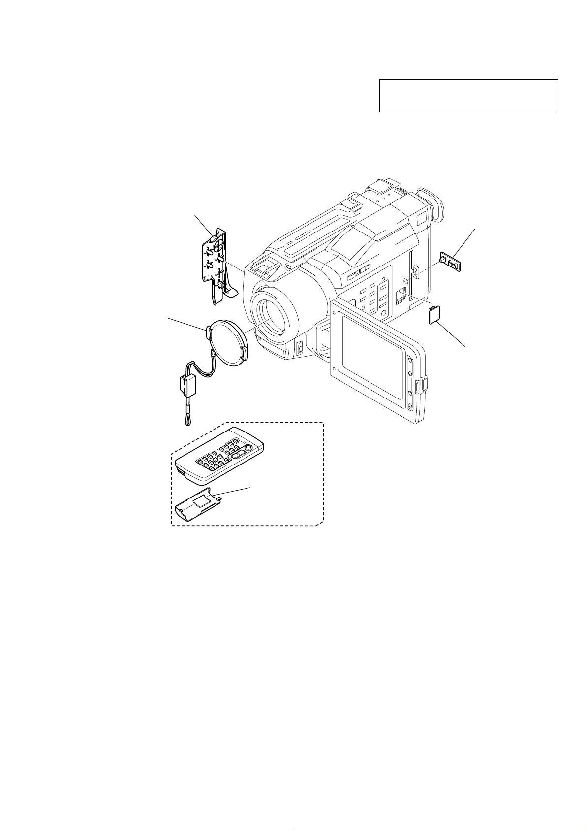
1. ORNAMENTAL PARTS
Jack cover
3-058-723-01
Lens cap assembly
X-3949-376-1
DCR-TR V820E
The components identified by mark 0 or dotted
line with mark 0 are critical for safety.
Replace only with part number specified.
Jack lid
3-987-656-01
Battery case lid
3-742-854-01
Remote commander (RMT-814)
1-475-141-61
CPC lid (103P)
3-059-539-01
– 9 –
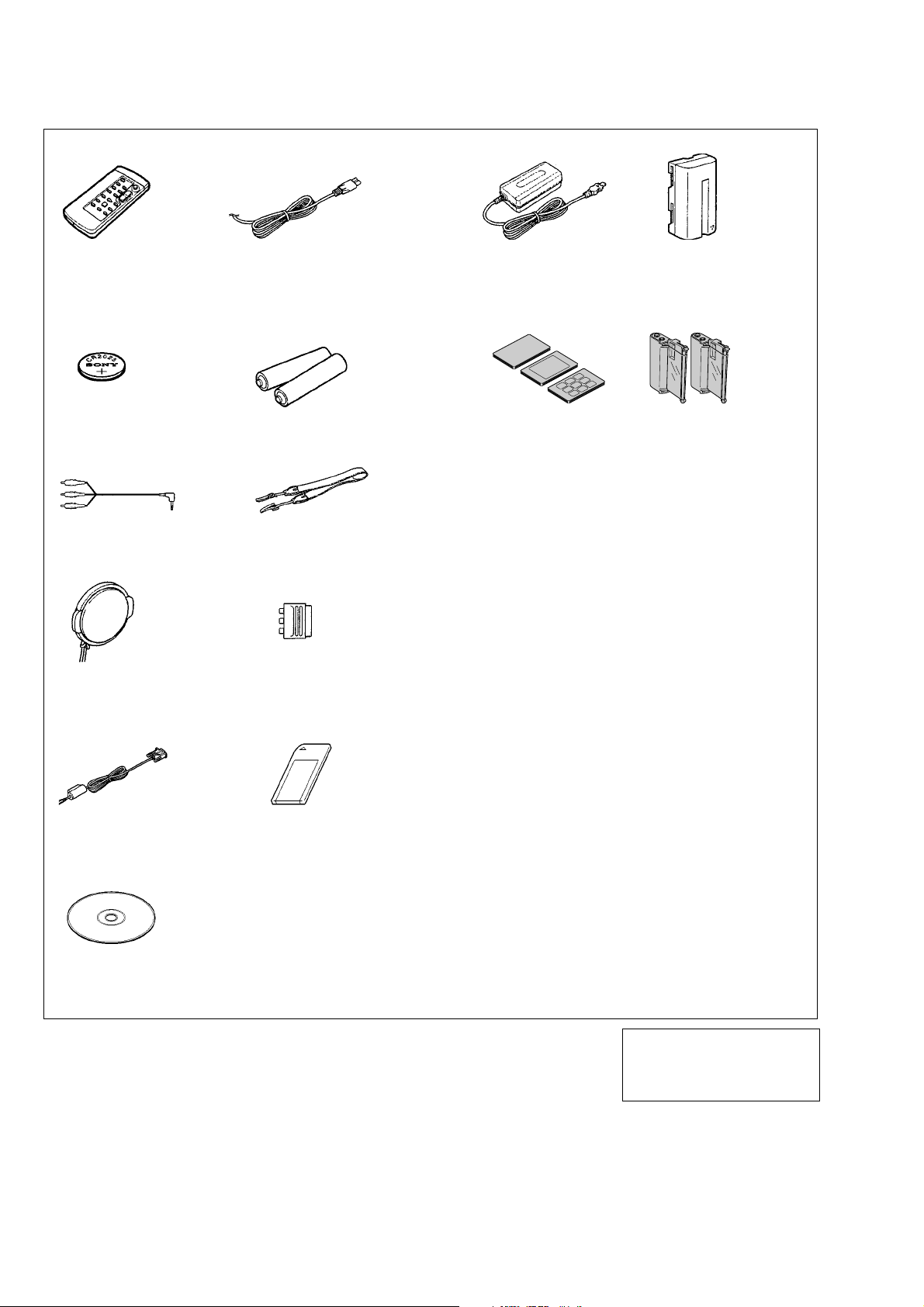
Checking supplied accessories.
Check that the following accessories are supplied with your camcorder.
Wireless Remote
Commander (1)
RMT-814
1-475-141-61
CR2025 lithium battery (1)
The lithium battery is already
installed in your camcorder.
A/V connecting cable (1)
1-765-080-11
Lens cap (1)
X-3949-376-1
Power cord (1)
0 1-769-608-11 (AEP)
0 1-783-374-11 (UK)
R6 (Size AA) battery
for Remote Commander (2)
Shoulder strap (1)
3-987-015-01
21-pin adaptor (1)
1-573-291-11
AC-L10A/L10B/L10C
AC power adaptor (1)
0 1-475-599-11
Print paper
Standard type
(20 sheets × 1)
Sticker type/Standard size
(10 sheets × 1)
Sticker type/9 split size
(10 sheets × 1)
NP-F330 battery pack (1)
0 A-7094-141-A
Print Cartridge (2)
Other accessories
3-059-565-11 MANUAL, INSTRUCTION (ENGLISH, RUSSIAN)
3-059-565-21 MANUAL, INSTRUCTION
3-059-565-31 MANUAL, INSTRUCTION (ITALIAN, DUTCH) (AEP)
3-059-565-41 MANUAL, INSTRUCTION (FRENCH, GERMAN) (AEP)
3-060-458-11 MANUAL, INSTRUCTION (Picture Gear 4.1Lite)
(SPANISH, PORTUGUESE) (AEP)
(ENGLISH, RUSSIAN)
1-792-451-11
Application software:
Picture Gear 4.1 Lite
(CD-ROM) (1)
3-060-476-01
3-060-458-21 MANUAL, INSTRUCTION (Picture Gear 4.1Lite)
3-060-458-31 MANUAL, INSTRUCTION (Picture Gear 4.1Lite)
“Memory Stick” (1)PC serial cable (1)
3-060-458-41 MANUAL, INSTRUCTION (Picture Gear 4.1Lite)
The components identified by mark
0 or dotted line with mark 0 are
critical for safety.
Replace only with part number specified.
(FRENCH, GERMAN) (AEP)
(ITALIAN, DUTCH) (AEP)
(SPANISH, PORTUGUESE) (AEP)
– 10 –
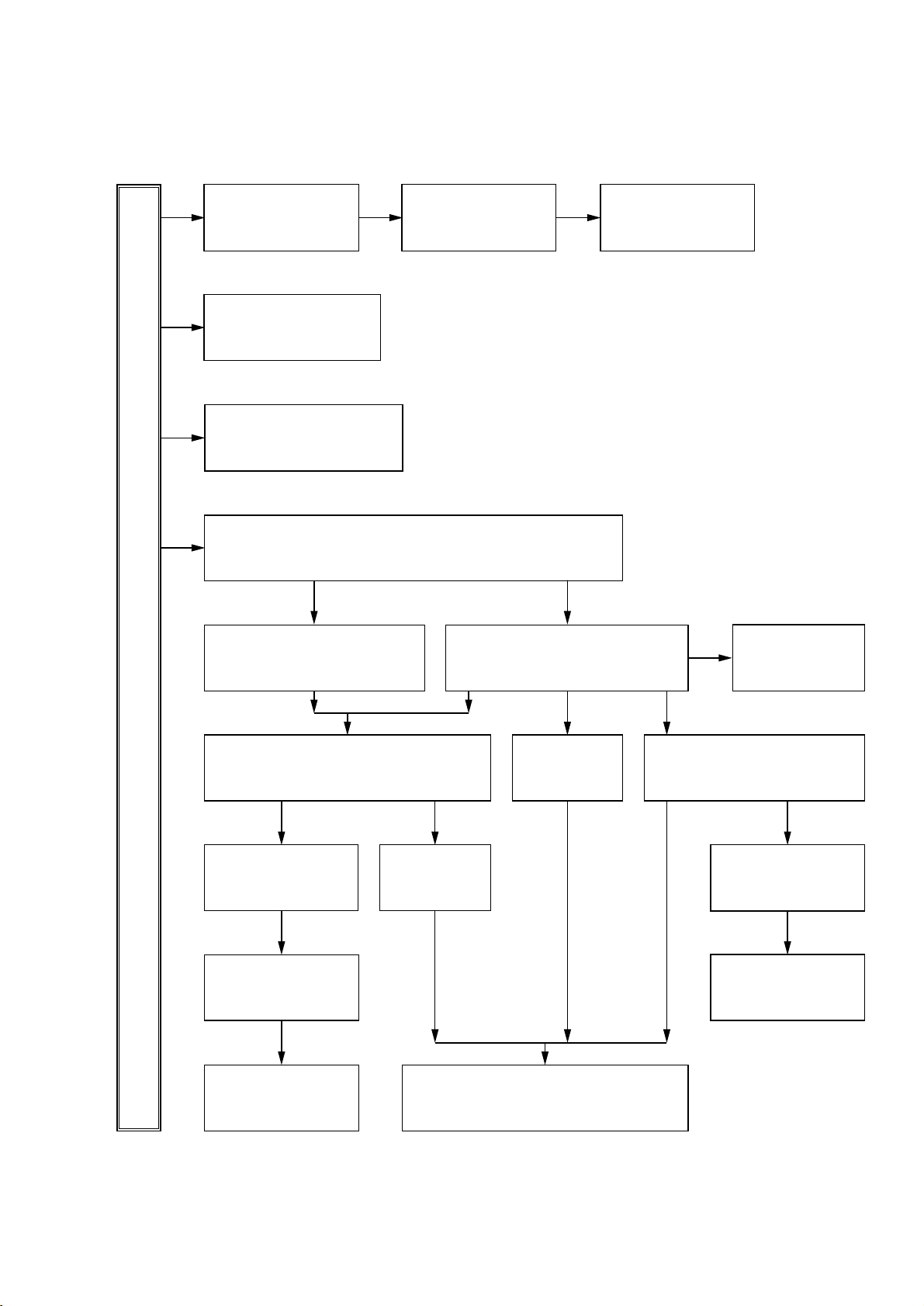
2. DISASSEMBLY
DCR-TRV820E
2-1. LCD ASSEMBLY
(page 12)
2-4. VF-141 BOARD,
VF LENS ASSEMBLY
(page 12)
2-12. FP-162 FLEXIBLE
BOARD
(page 14)
2-14. PRINTER UNIT
(page 15)
2-6. CASSETTE LID ASSEMBLY
(page 13)
2-7. CABINET (L) ASSEMBLY
(page 13)
2-17. CONTROL SWITCH
BLOCK (FK-10000)
(page 16)
2-16. SE-114 BOARD
(page 15)
2-18. FU-141
BOARD
(page 16)
2-19. VC-235 BOARD
(page 16)
2-10. PC-78
BOARD
(page 14)
2-13. PR-33 BOARD
(page 15)
2-11. BATTERY PANEL ASSEMBLY
(page 14)
2-15. LENS BLOCK
(page 15)
2-8. CABINET (R) ASSEMBLY
(page 13)
2-9. CF-72 BOARD
(page 14)
2-5. FRONT PANEL ASSEMBLY
(page 13)
2-2. PD-118 BOARD
(page 12)
2-3. LCD MODULE
(page 12)
• This set can be disassembled in the order shown below.
DCR-TR V820E
– 11 –
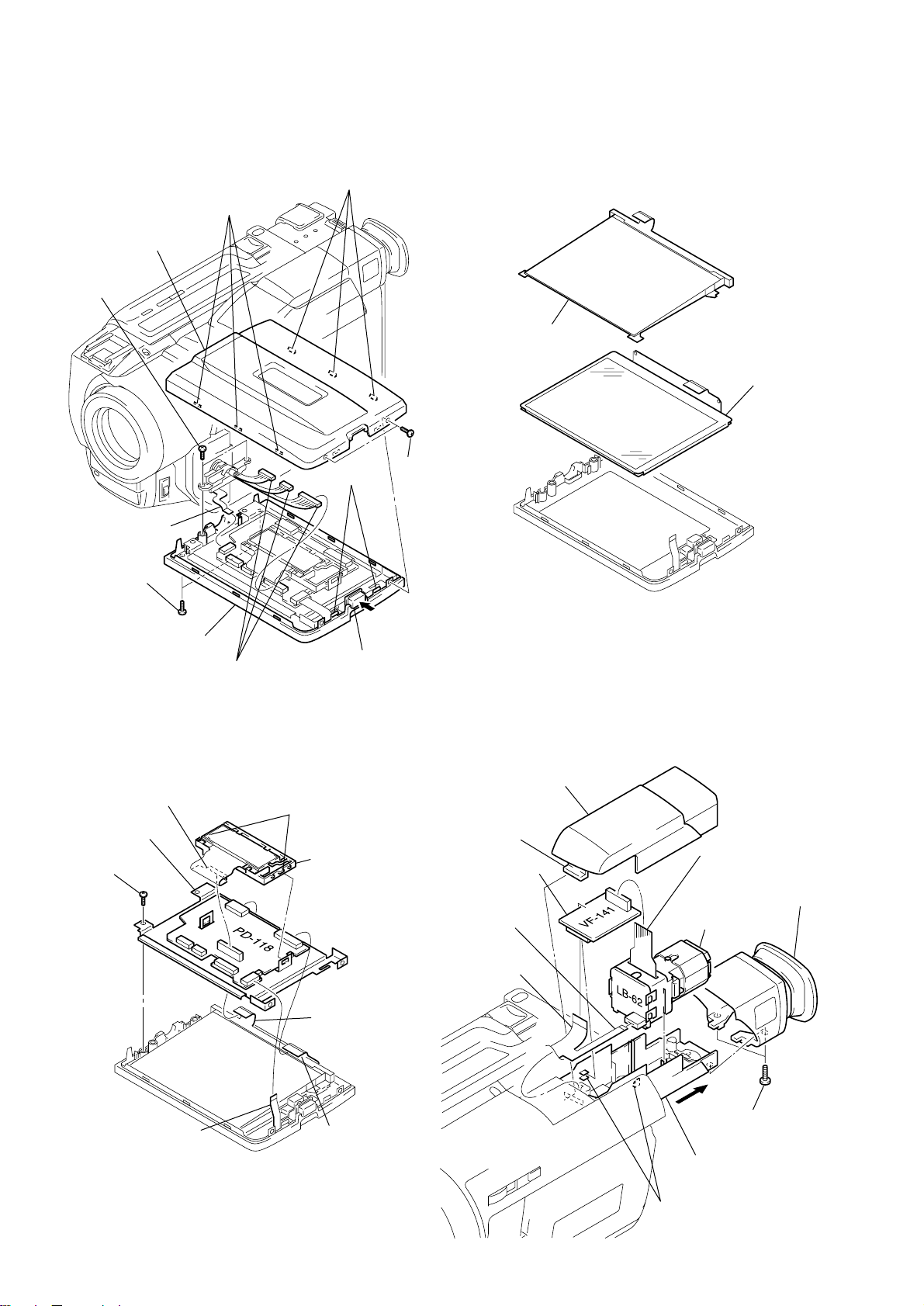
Note: Follow the disassembly procedure in the numerical order given.
2-1. LCD ASSEMBLY 2-3. LCD MODULE
5 Three claws
6 Three claws
7 P cabinet (C)
0 Two screws
1 Cold cathode
fluorescent
tube
2 LCD module
9 Flexible board
(CN5703)
3 Two screws
qa LCD assembly
8 Three connectors
2-2. PD-118 BOARD
6 Flexible board
(CN5705)
5 PD-118 board
4 Screw
(4 LCD model only)
(CN5701, 5702, 5704)
7 Two claws
4 Two claws
1 Open the
8 Indication (LCD)
block assembly
2 Two screws
LCD panel.
(P2 × 4)
2-4. VF-141 BOARD,
VF LENS ASSEMBLY
5 EVF cabinet (upper)
4 Claw
8 VF-141 board
0 Flexible board
(CN4601)
6 Flexible board
(CN4502)
3 EVF cabinet
(rear) assembly
qa VF lens assembly
1 Flexible board
(CN5708)
9 Flexible board
(CN4501)
3 Flexible board
(CN5604)
2 Two screws
2 Flexible board
(CN5501)
1 Pull out the
EVF block.
7 Two claws
– 12 –
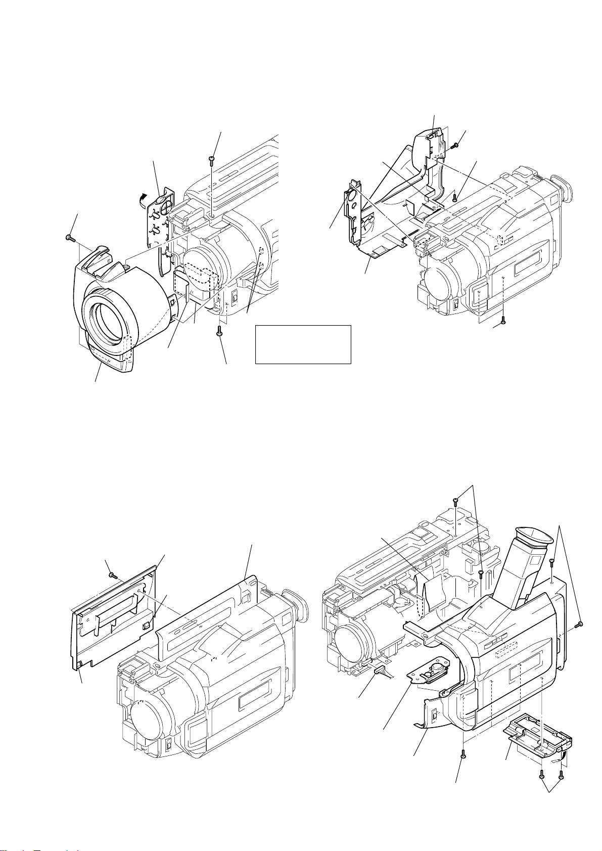
2-5. FRONT PANEL ASSEMBLY
2-7. CABINET (L) ASSEMBLY
2 Jack cover
3 Two screws
(2 × 4)
7 Flexible board
6 Front panel assembly
(CN5804)
1 Screw (2 × 4)
Cushion
(SE)
4 Two screws
(2 × 4)
5 Two claws
Note: Remove it while
taking care as
the flexible board
is connected.
7 Flexible board
(CN253)
4 Claw
6 Cabinet (L) assenbly
5 Claw
3 Two screws
1 Two screws
(2 × 4)
2 Screw (2 × 4)
(2 × 4)
2-6. CASSETTE LID ASSEMBLY
1 Two screws
(2 × 4)
3 Claw
5 Cassette lid assembly
2 Open the control switch block.
4 Claw
2-8. CABINET (R) ASSEMBLY
4 Two screws
(2 × 4)
7 Flat cable
(CN001)
8 Connector
(CN1109)
9 Screw
(tripod)
3 Two screws
(2 × 4)
– 13 –
6 Cabinet (R)
assembly
2 Ribbon lid
assembly
5 Three screws
(2 × 4)
1 Four screws
(2 × 4)
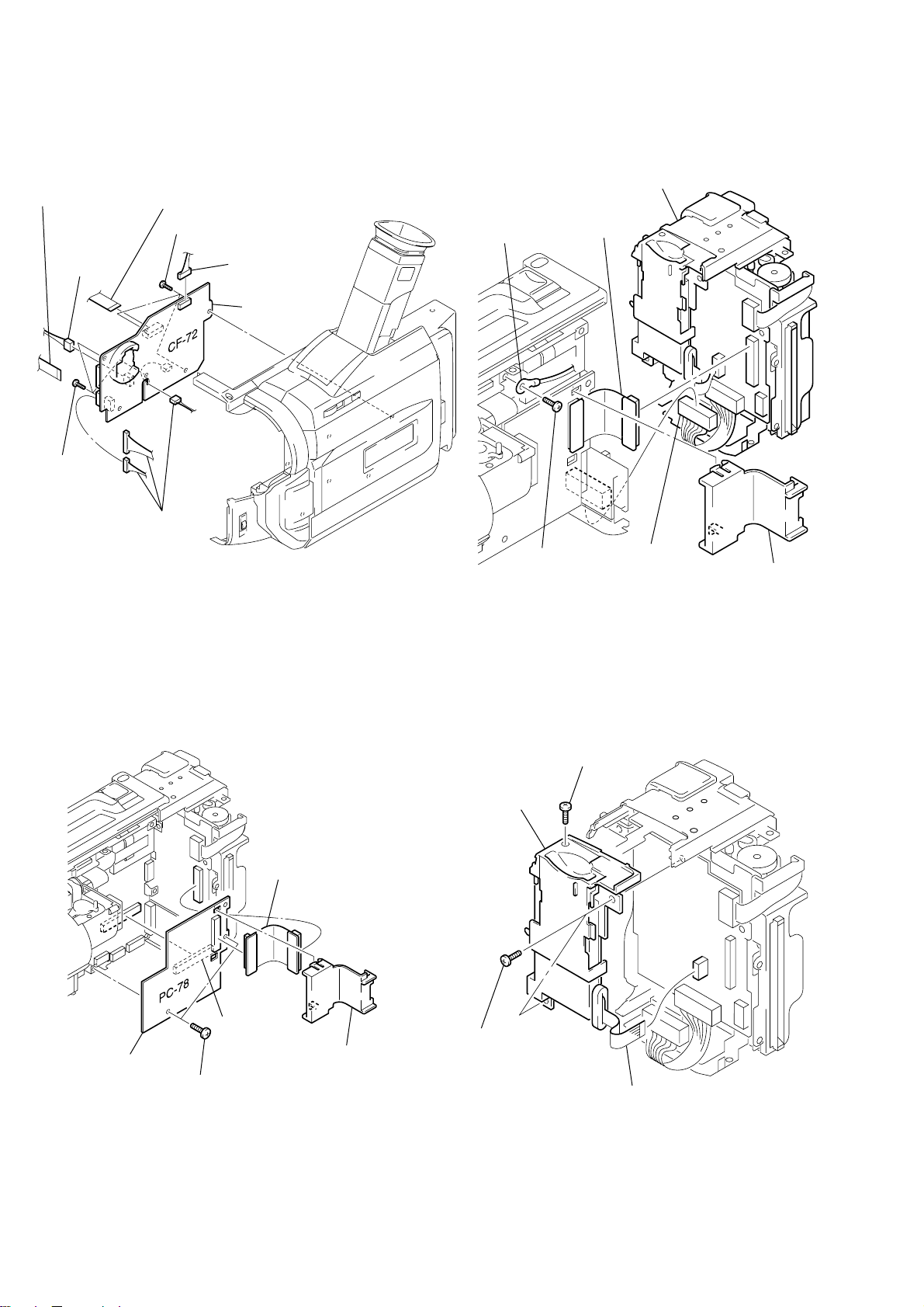
2-9. CF-72 BOARD 2-11. BATTERY PANEL ASSEMBLY
6 Battery panel
assembly
2 Connector
(CN255)
2 Flexible
board
(CN002)
3 Connector
(CN008)
6 Three
screws
1 Three connectors
4 Flexible board
(CN006)
7 Three screws
(CN003, 004, 005)
5 Connector
(CN009)
8 CF-72 board
5 Harness
(HT-054)
3 Flexible board
(CN702)
4 Screw
(2 × 3)
1 CN clip
2-10. PC-78 BOARD
5 PC-78 board
3 Two screws
4 Connector
(CN801)
(2 × 3)
2 FP-163
flexible board
1 CN clip
2-12. FP-162 FLEXIBLE BOARD
3 Screw
(2 × 4)
4 FP-162
flexible board
2 Two screws
(2 × 3)
1 Flexible board
(CN703)
– 14 –
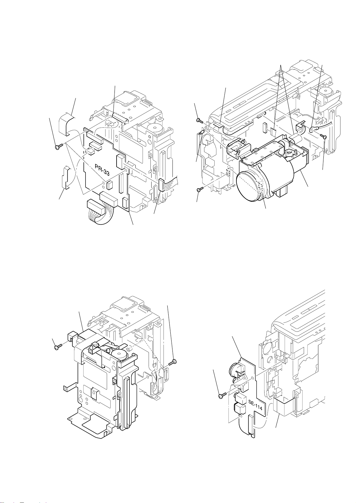
2-13. PR-33 BOARD
2 Four screws
(2 × 3)
1 Flexible board
(CN202)
3 SE-114 board
2-15. LENS BLOCK
1 Two flexible baords
(CN1501, 1551)
5 Harness
(HT-054)
5 Three
screws
(2 × 3)
1 Flexible board
(CN704)
2 Flexible board
(CN706)
3 Flexible board
(CN708)
6 PR-33 board
4 Connector
(CN252)
3 Screw
(2 × 3)
6 Claw
2 Screw
9 Flexible board
(external connector)
(2 × 3)
4 Screw
(2 × 3)
8 Lens block
7 Lens frame
2-14. PRINTER UNIT 2-16. SE-114 BOARD
2 Three screws
(2 × 4)
3 Printer unit
1 Screw
(2 × 3)
– 15 –
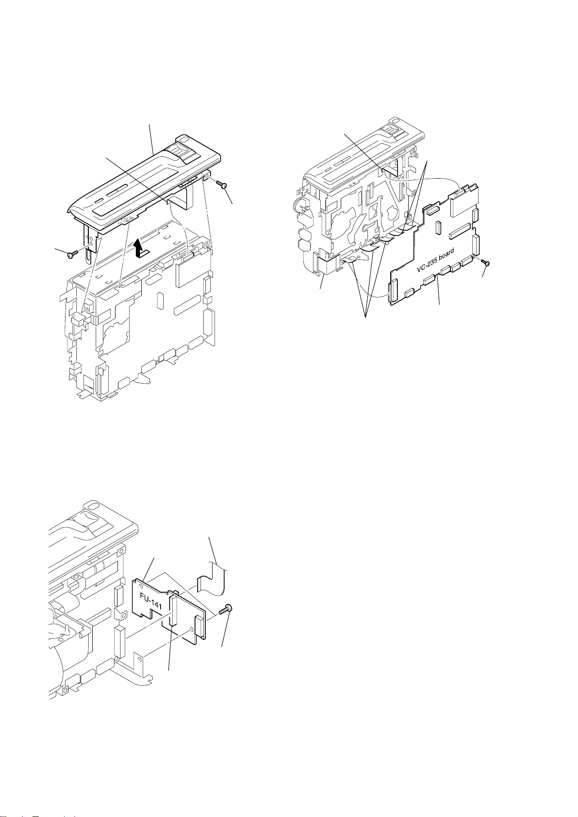
2-17. CONTROL SWITCH BLOCK (FK-10000)
4 Remove the control switch block (FK-10000)
in the direction of the arrow.
1 Flexible board
(CN1107)
2 Screw
3 Screw
(2 × 3)
(2 × 3)
2-19. VC-235 BOARD
1 Flexible board
(CN1107)
2 Flexible board
(CN1103)
3 Three flexible boards
(CN3101, 4401, 4402)
4 Two flexible boards
(CN4403, 4404)
5 Screw
(2 × 3)
6 VC-235 board
2-18. FU-141 BOARD
1 Flexible board
(CN258)
4 FU-141 board
2 Two screws
(2 × 3)
3 Connector
(CN254)
– 16 –
3-1. EXPLODED VIEWS
NOTE:
• -XX and -X mean standardized parts, so they may
have some difference from the original one.
• Color Indication of Appearance Parts
Example:
KNOB, BALANCE (WHITE) . . . (RED)
↑↑
Parts Color Cabinet's Color
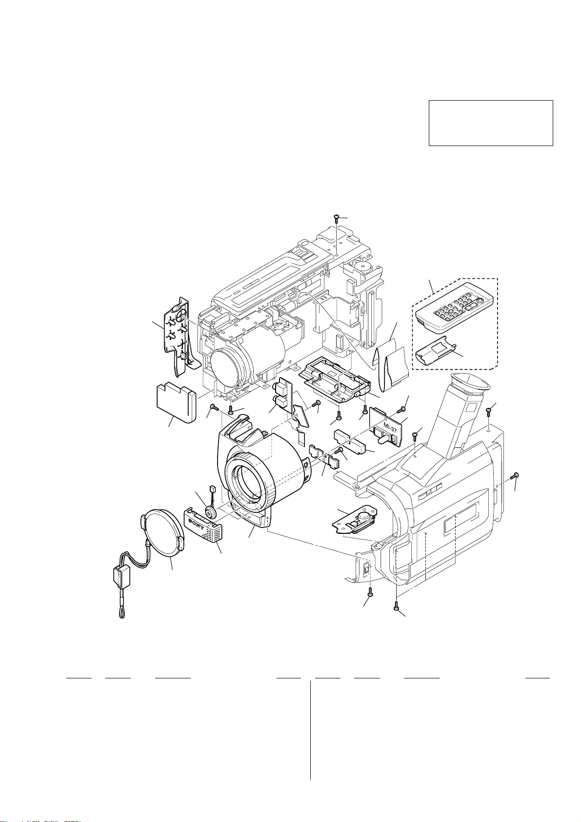
3-1-1. FRONT PANEL SECTION
3. REPAIR PARTS LIST
• Items marked “*” are not stocked since they are
seldom required for routine service. Some delay
should be anticipated when ordering these items.
• The mechanical parts with no reference number in
the exploded views are not supplied.
4
DCR-TR V820E
The components identified by mark
0 or dotted line with mark 0 are
critical for safety.
Replace only with part number specified.
14
13
12
MIC5802, 5803
1
11
15
7
4
4
10
7
4
16
9
4
4
4
8
7
6
4
5
3
2
1 X-3949-376-1 CAP (N) ASSY, LENS
2 X-3950-220-1 GRILLE (2.5) ASSY, MICROPHONE
3 X-3950-490-1 PANEL ASSY (1031), F
4 3-968-729-01 SCREW (2X4)
5 3-987-717-01 SCREW (TRIPOD)
6 X-3950-221-1 RETAINER ASSY, MICROPHONE
7 3-948-339-61 TAPPING
* 8 3-059-031-01 CUSHION (MI)
9 not supplied MI-37 BOARD, COMPLETE
4
4
Ref. No. Part No. Description RemarkRef. No. Part No. Description Remark
10 1-676-818-31 FP-156 FLEXIBLE BOARD
11 1-790-334-11 CABLE, FLEXIBLE FLAT (FFC-257S)
* 12 3-059-032-01 CUSHION (SE)
13 3-058-723-01 COVER, JACK
14 1-475-141-61 COMMANDER, REMOTE (RMT-814)
15 3-742-854-01 LID, BATTERY (for RMT-814)
16 X-3950-423-1 LID ASSY, RIBBON
MIC5802 1-542-312-11 MICROPHONE (L)
MIC5803 1-542-312-11 MICROPHONE (R)
– 17 –
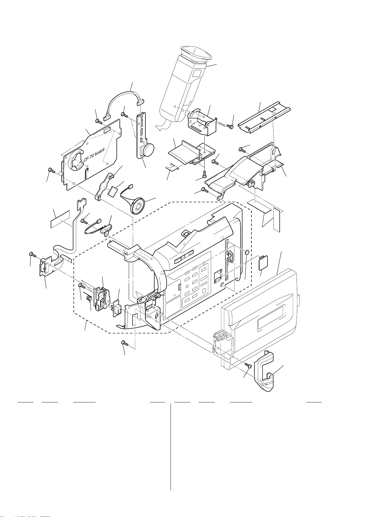
3-1-2. CABINET (R) SECTION
EVF block
(See page 20)
62
52
52
57
58
61
52
52
55
S008S008
54
52
60
59
63
64
SP003
66
65
52
68
52
67
56
69
65
70
58
LCD assembly
(See page 19)
71
52
not
supplied
53
52
Ref. No. Part No. Description Remark
51 3-059-547-01 COVER (R) (103), HINGE
52 3-948-339-61 TAPPING
53 X-3950-442-1 CABINET (R) (103P) ASSY
54 3-059-533-01 KNOB (103), MF
55 3-059-532-01 RETAINER (103), MF
56 3-959-978-02 CUSHION, PANEL
57 1-418-801-11 SWITCH BLOCK, CONTROL (MF-10000)
58 3-941-343-21 TAPE(A)
* 59 3-058-658-01 SPACER (101), SPEAKER
* 60 3-058-659-01 RETAINER (101), SPEAKER
51
52
Ref. No. Part No. Description Remark
63 not supplied KP-009 BOARD, COMPLETE
* 64 3-058-640-01 RETAINER (100), HARNESS
65 3-968-729-01 SCREW (2X4)
66 X-3950-551-1 BASE (103) ASSY, SLIDE
67 3-948-339-81 TAPPING
68 X-3950-230-1 HINGE ASSY, VF
* 69 3-060-376-01 SHEET METAL (103), SLIDE
70 X-3950-553-1 BASE (103) ASSY, VF
71 3-059-539-01 LID (103P), CPC
S008 1-771-848-11 SWITCH, PUSH (PANEL OPEN/CLOSE)
61 not supplied CF-72 BOARD, COMPLETE
62 1-960-227-11 HARNESS (DP-87)
SP003 1-529-590-11 SPEAKER (2.0cm)
– 18 –
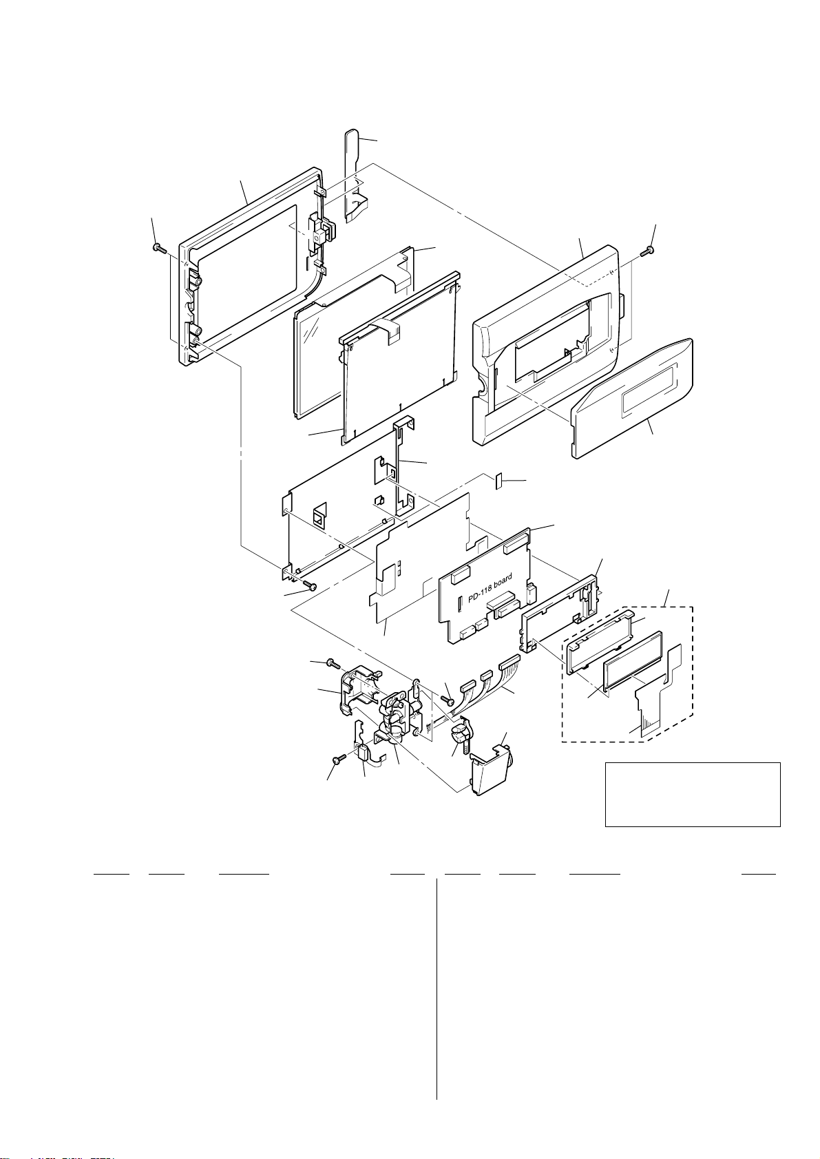
3-1-3. LCD ASSEMBLY SECTION
115
112
116
ND901
116
117
108
LCD901
118
114
120
113
111
110
LED901
119
108
107
109
104
105
Ref. No. Part No. Description Remark
101 3-059-548-01 COVER (C) (103), HINGE
102 3-948-339-31 SCREW, TAPPING
* 103 3-058-672-01 CLAMP, HARNESS
104 1-418-802-11 SWITCH BLOCK, PANEL REVERSE (PR-10000)
105 4-981-286-01 SCREW (M1.7X2) (IB LOCK)
106 1-960-225-11 HARNESS (DP-83)
107 3-058-673-01 COVER (M), HINGE
108 3-968-729-01 SCREW (2X4)
109 X-3950-237-1 HINGE ASSY
110 not supplied INDICATION (LCD) BLOCK ASSY (SERVISE)
111 3-058-715-01 HOLDER (102), LCD
112 1-418-803-11 SWITCH BLOCK, CONTROL (BV-10000)
113 not supplied PD-118 BOARD, COMPLETE (TYPE S)
113 not supplied PD-118 BOARD, COMPLETE (TYPE C)
102
106
101
103
Ref. No. Part No. Description Remark
114 3-059-546-01 FRAME (103), PANEL
115 X-3950-444-1 CABINET (M) (103) ASSY, P
116 3-948-339-81 TAPPING
117 X-3950-445-1 CABINET (C) (103) ASSY, P
118 3-059-549-31 WINDOW (103), LCD
* 119 3-058-720-01 INSULATING SHEET (B (102)), PD
* 120 3-062-064-01 PD SHEET
LCD901 not supplied INDICATOR MODULE, LIQUID CRYSTAL
LCD901 not supplied INDICATOR MODULE, LIQUID CRYSTAL
0 LED901 not supplied LIGHT, BACK
0 ND901 not supplied TUBE, FLUORESCENT, COLD CATHODE
not
supplied
(LCD902)
not supplied
The components identified by mark
0 or dotted line with mark 0 are
critical for safety.
Replace only with part number specified.
(TYPE C)
(TYPE S)
– 19 –
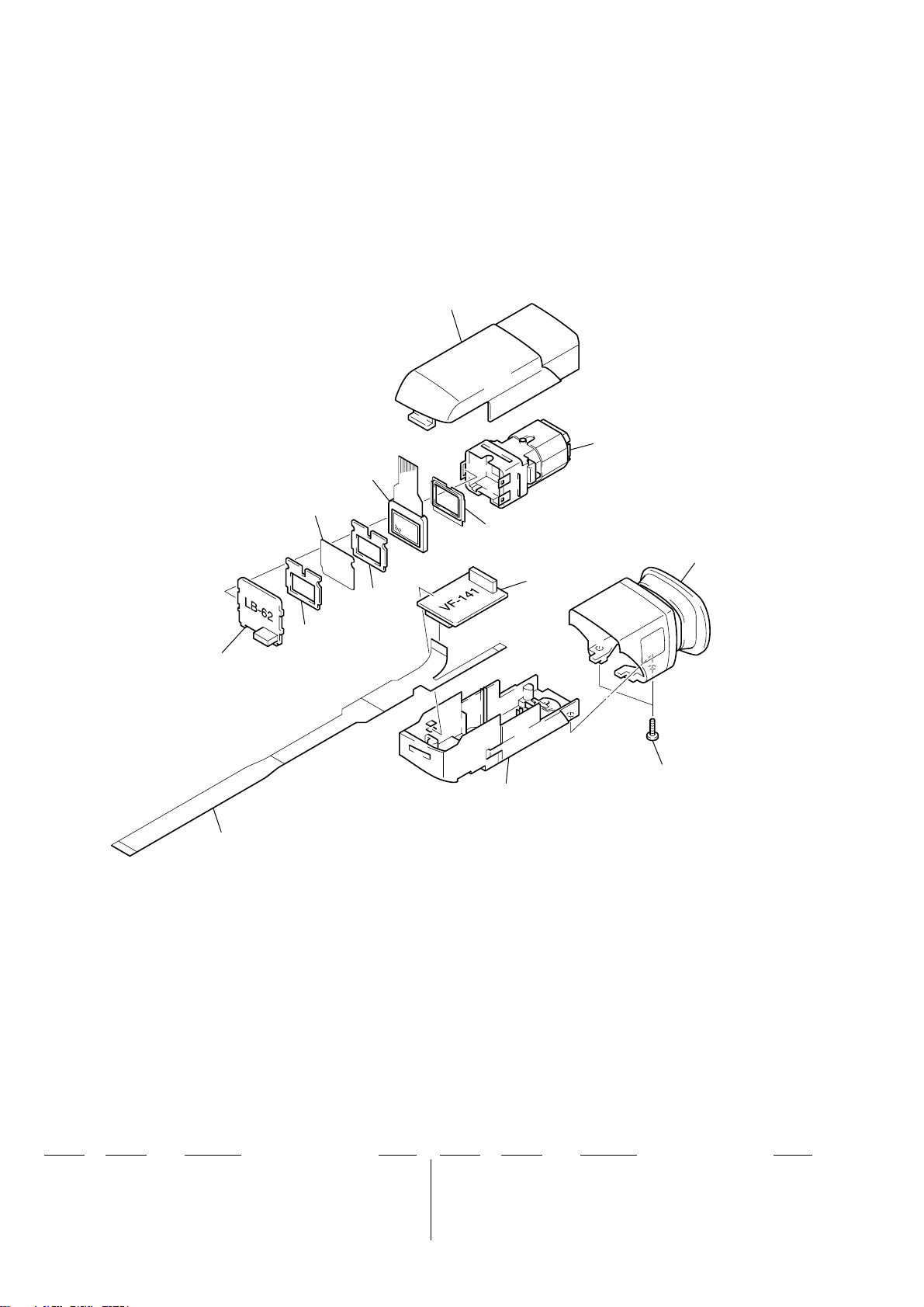
3-1-4. EVF BLOCK SECTION
154
155
LCD903
153
not supplied
156
152
151
157
not
supplied
not supplied
158
159
Ref. No. Part No. Description Remark
151 1-676-299-11 FP-151 FLEXIBLE BOARD
152 not supplied LB-62 BOARD, COMPLETE
153 not supplied ILLUMINATOR (97), BL
154 3-060-370-01 CABINET (UPPER) (103), EVF
155 X-3950-101-1 LENS (C) (97) ASSY, VF
Ref. No. Part No. Description Remark
156 X-3950-550-1 CABINET (REAR) (103) ASSY, EVF
157 not supplied VF-141 BOARD, COMPLETE
158 3-948-339-81 TAPPING
159 X-3950-549-1 CABINET (LOWER) (103) ASSY, EVF
LCD903 not supplied LCX032AK-1
– 20 –
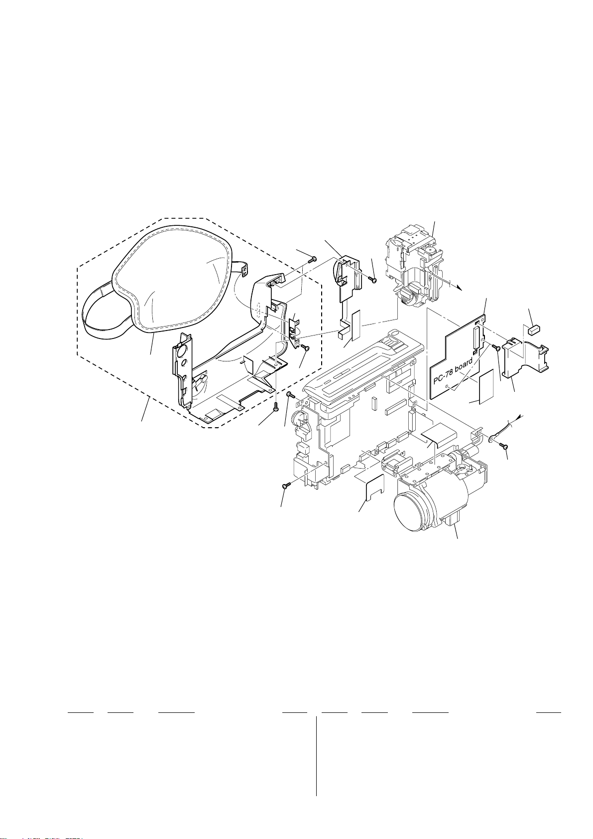
3-1-5. CABINET (L) SECTION
202
Battery panel block
(See page 22)
206
204
203
205
202
201
201
not
supplied
204
208
209
211
210
213
Lens block
(See page 23)
212
201
207
201
201 3-713-786-21 SCREW (M2X3)
202 3-968-729-01 SCREW (2X4)
203 X-3950-453-1 CABINET (L) ASSY
204 3-948-339-81 TAPPING
205 3-052-815-01 BELT (ES), GRIP
206 1-418-800-11 SWITCH BLOCK, CONTROL (SS-10000)
* 207 3-061-054-01 CLIP, CN
Ref. No. Part No. Description RemarkRef. No. Part No. Description Remark
208 3-941-343-21 TAPE (A)
* 209 3-059-461-01 SHEET, RP SHIELD
210 not supplied PC-78 BOARD, COMPLETE
* 211 3-062-065-01 FK SHEET
* 212 3-062-546-01 SPACER, PC
213 3-061-982-01 SHEET (S), ELECTROSTATIC
– 21 –
 Loading...