

Page 1

DCR-TRV8/TRV8E/TRV10/TRV10E
RMT-808/809/811/812
Ver 1.2 1999. 10
SERVICE MANUAL
D300 MECHANISM
With SUPPLEMENT-1 (9-974-161-82)
With CORRECTION-1 (9-974-161-91)
Photo: DCR-TRV10
RMT-811
US Model
Canadian Model
DCR-TRV8/TRV10
AEP Model
UK Model
Australian Model
Chinese Model
DCR-TRV8E/TRV10E
E Model
Hong Kong Model
DCR-TRV8/TRV8E/TRV10/TRV10E
Tourist Model
DCR-TRV10/TRV10E
DCR-TRV8/TRV10: NTSC model
DCR-TRV8E/TRV10E: PAL model
For MECHANISM ADJUSTMENTS, refer to the “DV MECHANICAL
ADJUSTMENT MANUAL
11, supplement: 9-973-815-81) and “DV MECHANICAL
ADJUSTMENT MANUAL
981-11).
SPECIFICATIONS
D MECHANISM ” (original: 9-973-815-
D200 MECHANISM ” (original: 9-973-
MICROFILM
— Continued on next page —
DIGITAL VIDEO CAMERA RECORDER
Page 2

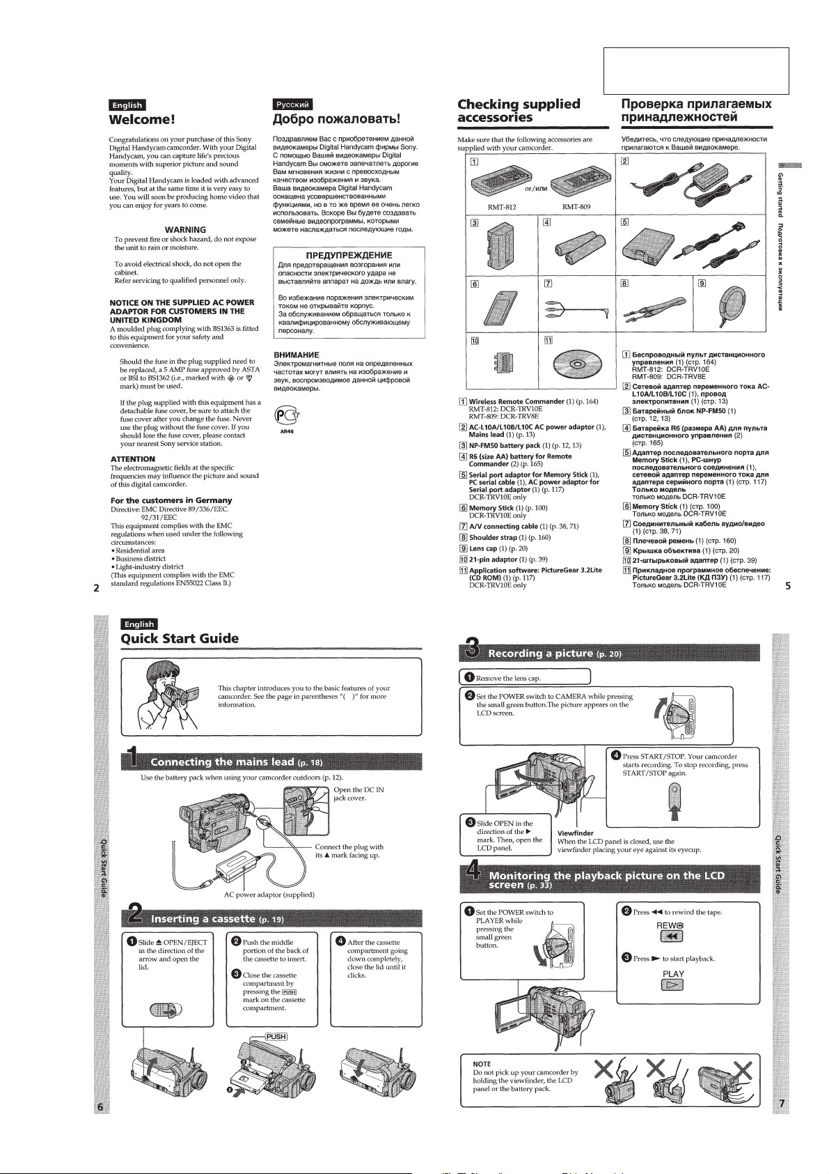
• SUPPLIED ACCESSORIES
Check that the following accessories are supplied with your
camcorder.
• DIFFERENCE TABLE
Model
Color System
Remote Commander
Lens
Memory Stick
Memory Key
DV
AUDIO/VIDEO
COMPONENTS IDENTIFIED BY MARK ! OR DO TTED LINE WITH
MARK ! ON THE SCHEMATIC DIAGRAMS AND IN THE PARTS
LIST ARE CRITICAL TO SAFE OPERATION. REPLACE THESE
COMPONENTS WITH SONY PARTS WHOSE PART NUMBERS
APPEAR AS SHOWN IN THIS MANUAL OR IN SUPPLEMENTS
PUBLISHED BY SONY.
Optical
Digital
SAFETY-RELATED COMPONENT WARNING!!
DCR-TRV8
NTSC
RMT-808
10 ×
120 ×
—
—
IN/OUT
IN/OUT
DCR-TRV8E
PAL
RMT-808
RMT-809 *
10 ×
120 ×, 40 × *
—
—
IN/OUT
* OUT_ONLY
IN/OUT
* OUT_ONLY
DCR-TRV10
SAFETY CHECK-OUT
After correcting the original service problem, perform the following
safety checks before releasing the set to the customer.
DCR-TRV10E
NTSC
RMT-811
10 ×
120 ×
g
g
IN/OUT
IN/OUT
LES COMPOSANTS IDENTIFÉS P AR UNE MARQUE ! SUR LES
DIAGRAMMES SCHÉMA TIQUES ET LA LISTE DES PIÈCES SONT
CRITIQUES POUR LA SÉCURITÉ DE FONCTIONNEMENT. NE
REMPLACER CES COMPOSANTS QUE PAR DES PIÈSES SONY
DONT LES NUMÉROS SONT DONNÉS DANS CE MANUEL OU
DANS LES SUPPÉMENTS PUBLIÉS PAR SONY.
PAL
RMT-811
RMT-812 *
10 ×
120 ×, 40 × *
g
g
IN/OUT
* OUT_ONLY
IN/OUT
* OUT_ONLY
ATTENTION AU COMPOSANT AYANT RAPPORT
*: AEP, UK model
À LA SÉCURITÉ!
• Abbreviation
AUS: Australian model
JE: Tourist model
CND: Canadian model
CN: Chainese mode
HK: Hong Kong model
1. Check the area of your repair for unsoldered or poorly-soldered
connections. Check the entire board surface for solder splashes
and bridges.
2. Check the interboard wiring to ensure that no wires are
"pinched" or contact high-wattage resistors.
3. Look for unauthorized replacement parts, particularly
transistors, that were installed during a previous repair . Point
them out to the customer and recommend their replacement.
4. Look for parts which, through functioning, show obvious signs
of deterioration. Point them out to the customer and
recommend their replacement.
5. Check the B+ voltage to see it is at the values specified.
6. Flexible Circuit Board Repairing
• Keep the temperature of the soldering iron around 270˚C
during repairing.
• Do not touch the soldering iron on the same conductor of the
circuit board (within 3 times).
• Be careful not to apply force on the conductor when soldering
or unsoldering.
— 2 —
Page 3

TABLE OF CONTENTS
SERVICE NOTE
1. POWER SUPPLY DURING REPAIRS ····························· 6
2. TO TAKE OUT A CASSETTE WHEN NOT EJECT
(FORCE EJECT) ································································6
SELF-DIAGNOSIS FUNCTION
1. SELF-DIAGNOSIS FUNCTION······································· 7
2. SELF-DIAGNOSIS DISPLAY ·········································· 7
3. SERVICE MODE DISPLAY ············································· 7
3-1. Display Method ·································································· 7
3-2. Switching of Backup No. ··················································· 7
3-3. End of Display···································································· 7
4. SELF-DIAGNOSIS CODE TABLE··································· 8
1. GENERAL
Welcome! ···················································································1-1
Checking supplied accessories ··················································1-1
Quick Start Guide ······································································1-1
Getting Started···········································································1-2
Using this manual ··································································1-2
Step 1 Preparing the power supply·······································1-2
Step 2 Inserting a cassette ····················································1-4
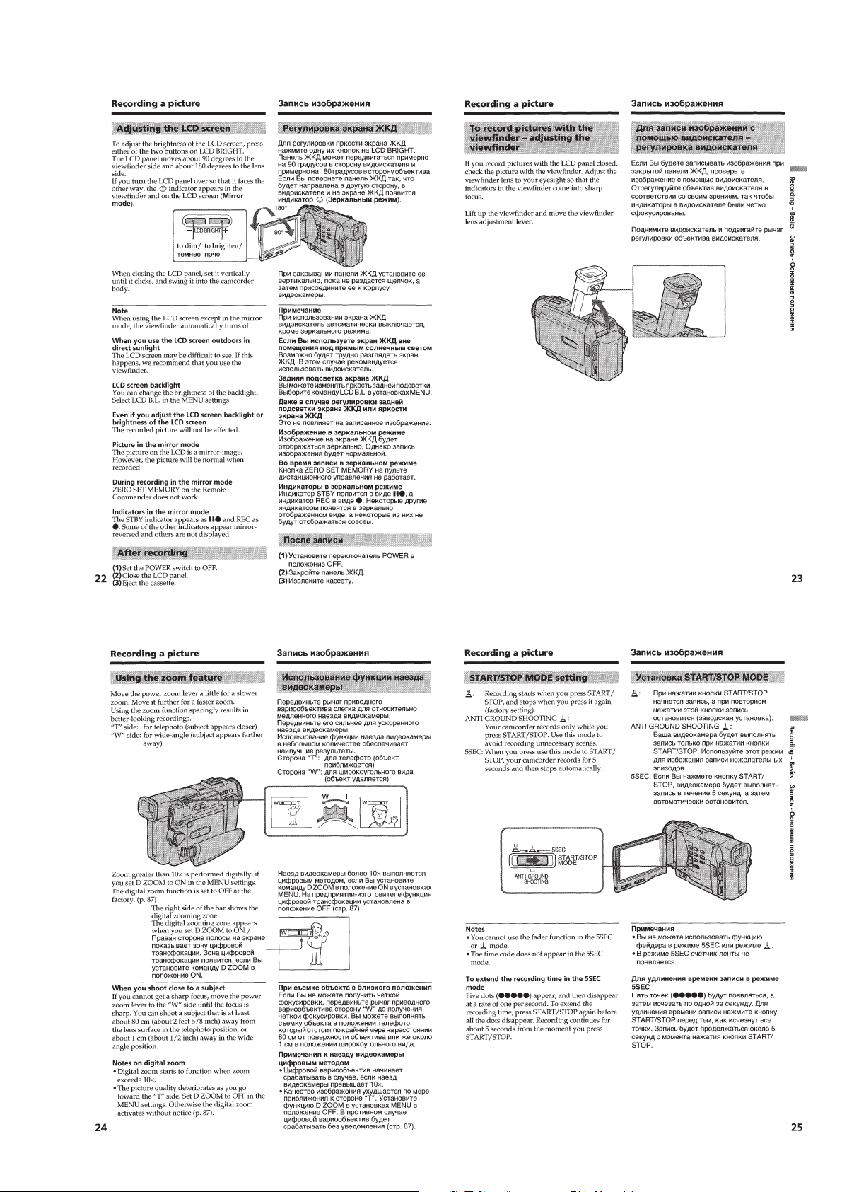
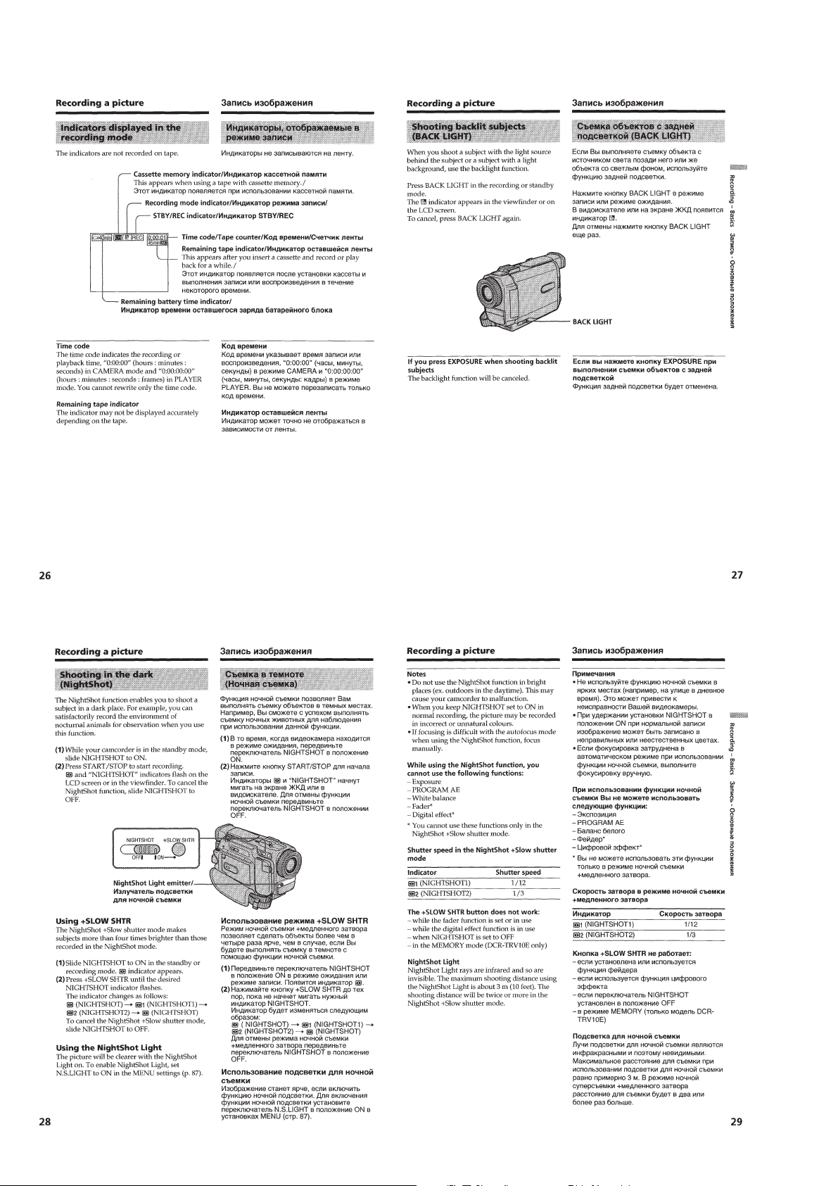
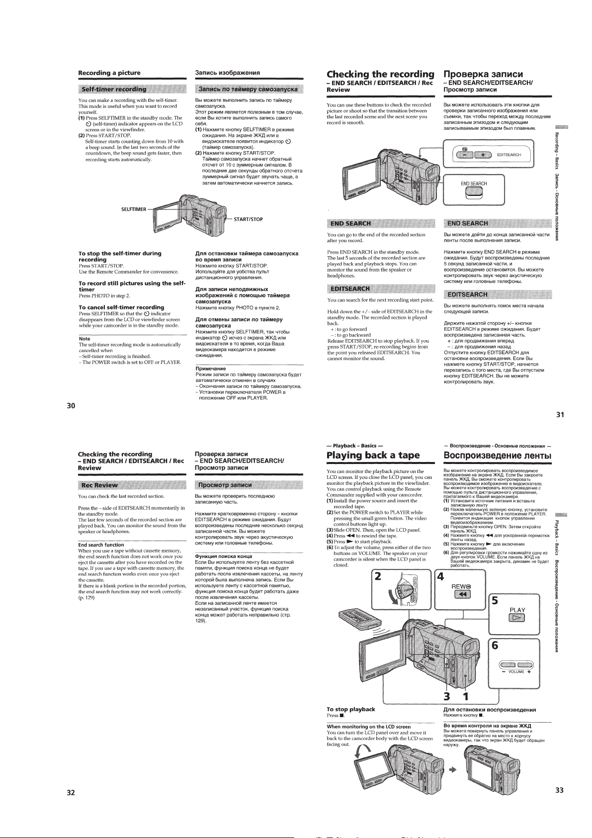
Recording – Basics ····································································1-4
Recording a picture································································1-4
Checking the recording
– END SEARCH/EDIT SEARCH/Rec Review····················1-7
Playback – Basics ······································································1-7
Playing back a tape ································································1-7
Viewing the recording on TV ················································1-9
Advanced Recording Operations···············································1-9
Photo recording······································································1-9
Using the wide mode ···························································1-10
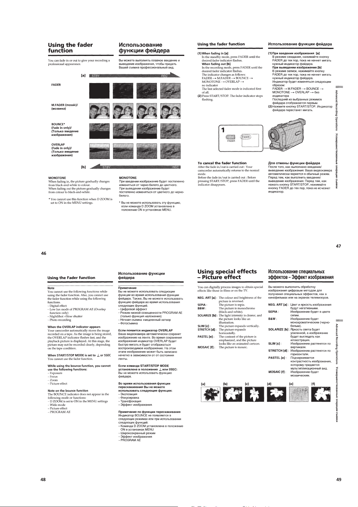
Using the fader function ······················································1-11
Using special effects – Picture effect···································1-11
Using special effects – Digital effect···································1-12
Adjusting the white balance manually································· 1-13
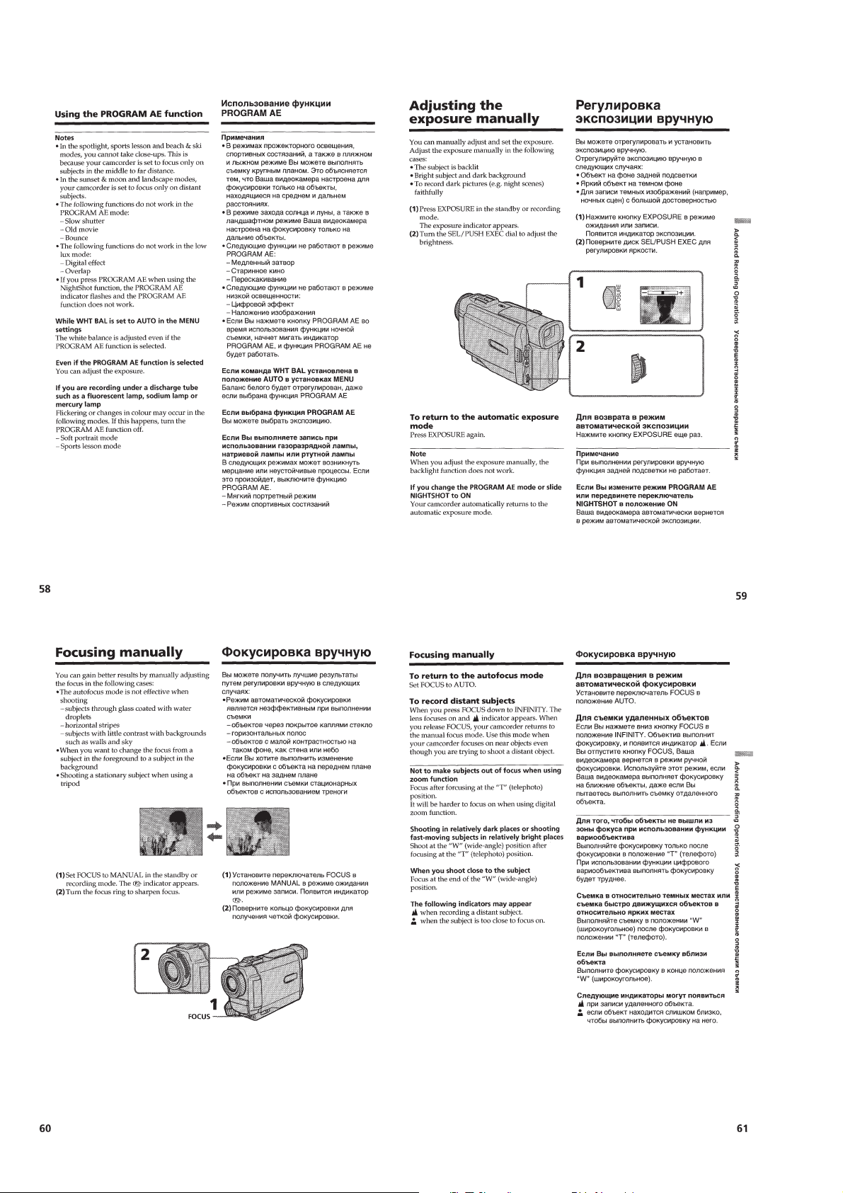
Using the PROGRAM AE function ·····································1-13
Adjusting the exposure manually ········································1-14
Focusing manually·······························································1-14
Advanced Playback Operations··············································· 1-15
Playing back a tape with picture effects ······························1-15
Playing back a tape with digital effects ·······························1-15
Quickly locating a scene using the
zero set memory function ·····················································1-15
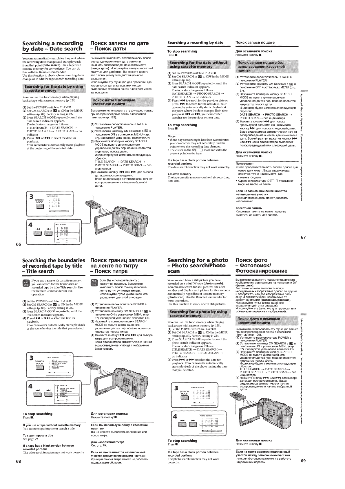
Searching a recording by date – Date search –····················1-16
Searching the boundaries of recorded tape by title
– Title search········································································ 1-16
Searching for a photo – Photo search/Photo scan················ 1-16
Editing ·····················································································1-17
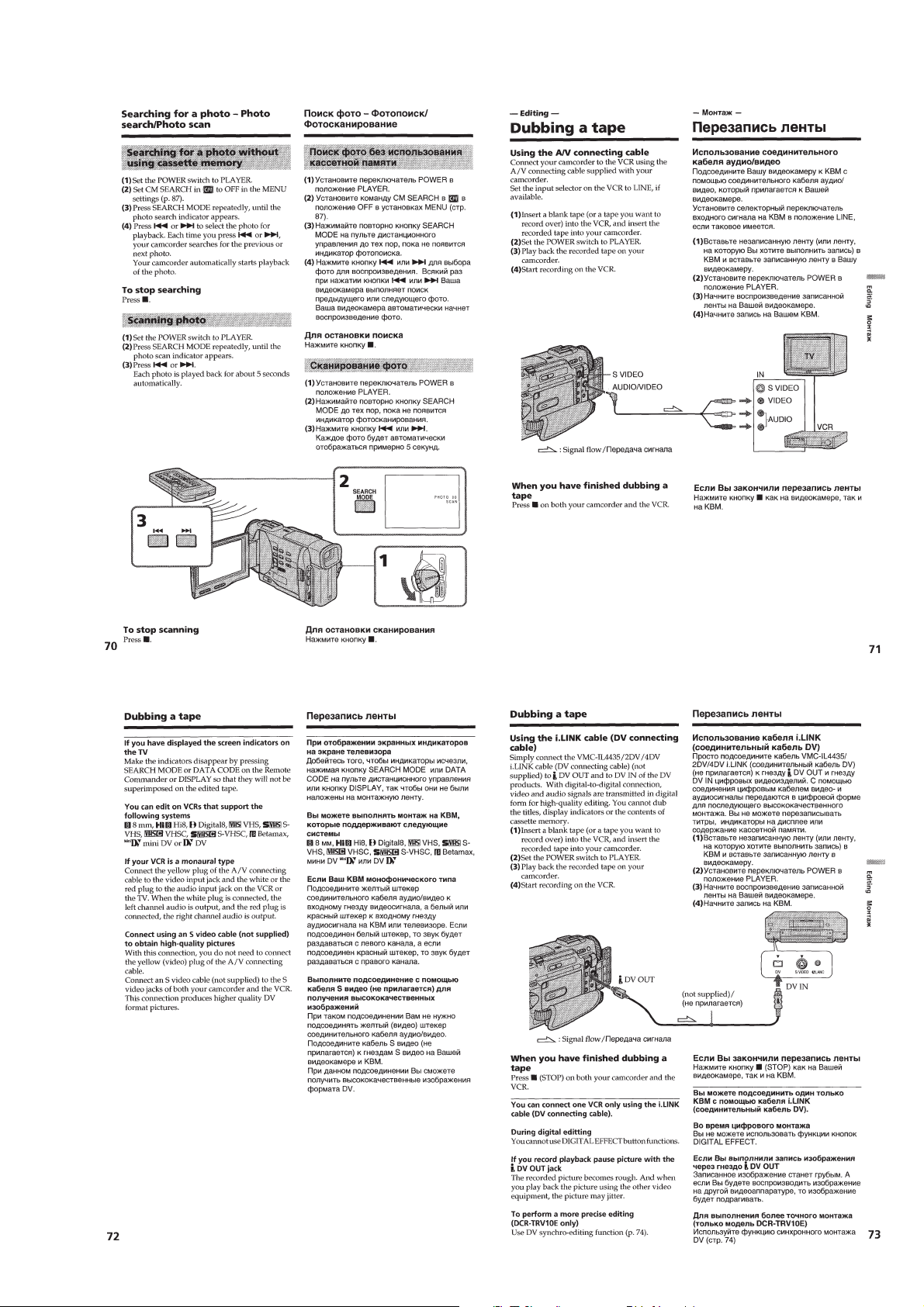
Dubbing a tape ·····································································1-17
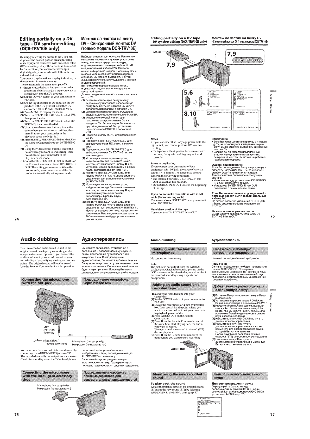
Editing partially on a DV tape – DV synchro-editing
(DCR-TRV10E only) ··························································· 1-18
Audio dubbing ·····································································1-18
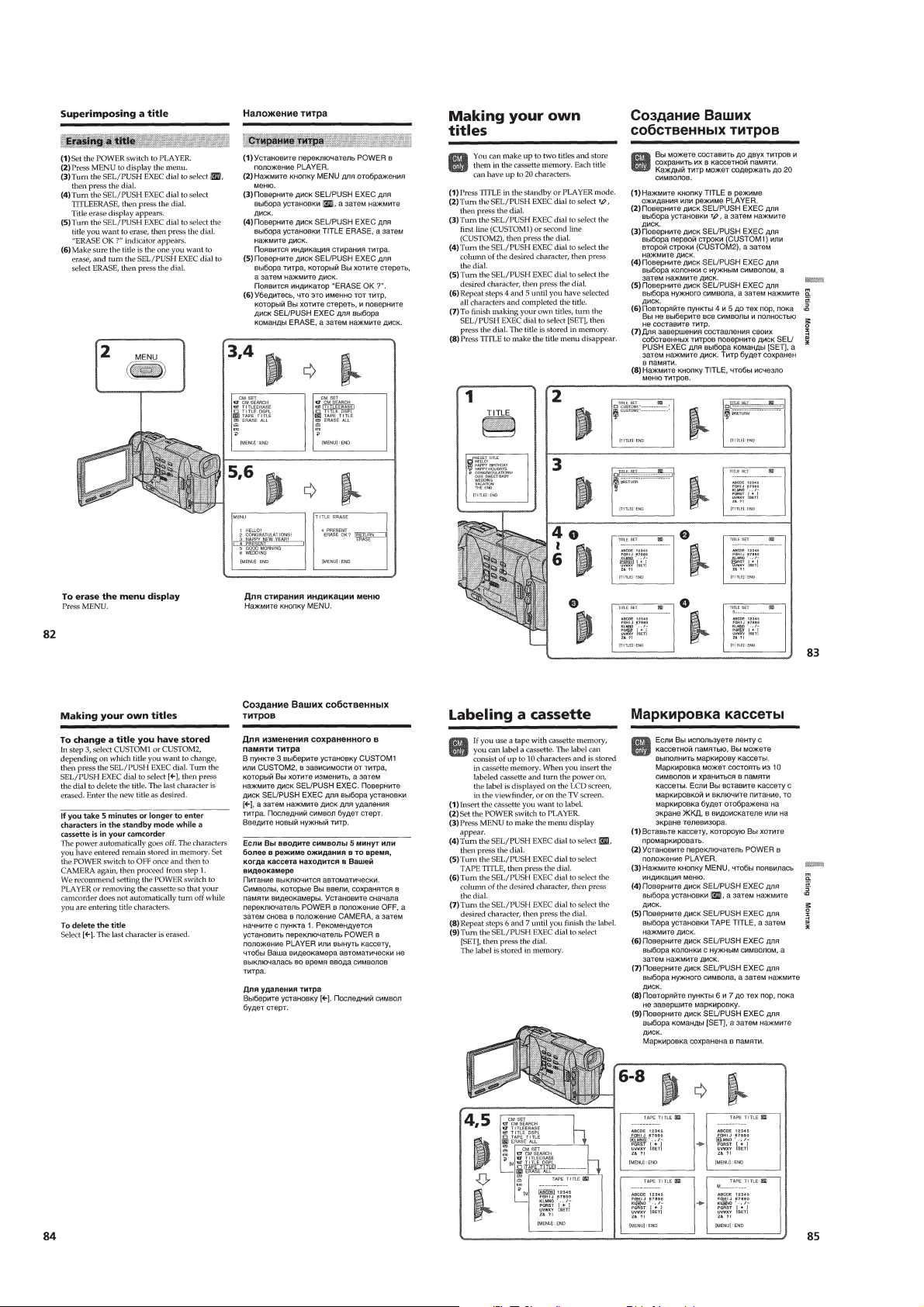
Superimposing a title ··························································· 1-19
Making your own titles ························································1-20
Labeling a cassette ·······························································1-20
Customizing Y our Camcorder ·················································1-21
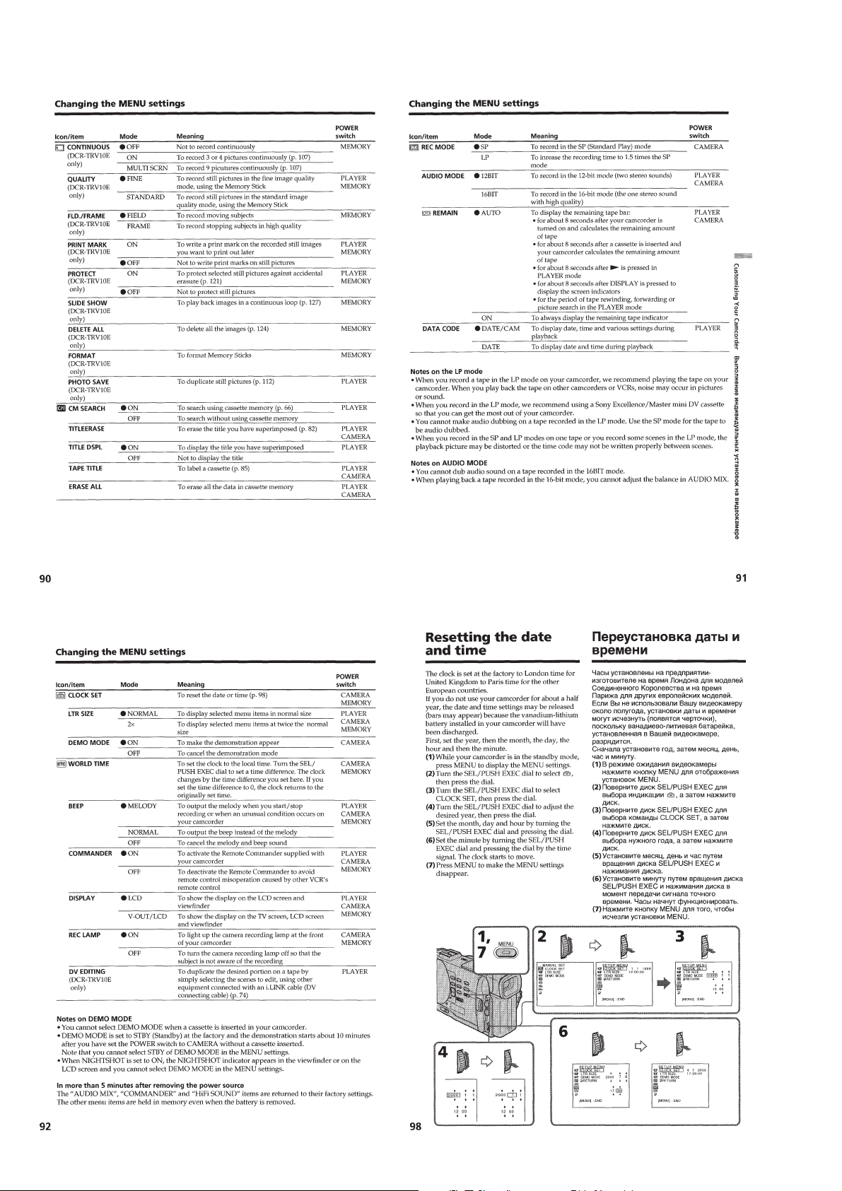
Changing the MENU settings ··············································1-21
Resetting the date and time··················································1-22
Memory Stick Operations························································1-23
Using a memory stick – introduction···································1-23
Recording still images on memory sticks
– Memory photo recording ··················································1-24
Recording an image from a mini DV tape
as a still image ····································································· 1-25
Copying still images from a recorded tape – Photo save ······· 1-26
Viewing a still picture – Memory photo playback···············1-26
Superimposing a still picture in a memory stick on a moving
picture– M. CHROM/M. LUMI/C. CHROM ······················1-27
Preventing accidental erasure – Image protection ···············1-28
Writing a print mark – PRINT MARK································1-29
Deleting images ···································································1-29
Playing back images in a continuous loop
–SLIDE SHOW ···································································1-30
Additional Information ····························································1-30
Usable cassettes ···································································1-30
Troubleshooting ···································································1-31
Self-diagnosis display ··························································1-32
Warning indicators and messages ········································1-32
Using your camcorder abroad·············································· 1-33
Maintenance information and precautions···························1-33
Quick Reference ······································································1-34
Identifying the parts and controls ········································1-34
2. DISASSEMBLY
2-1. LCD PANEL (PD-110 BOARD,
INVERT OR TRANS UNIT) ··········································· 2-1
2-2. FRONT PANEL ASSEMBLY·········································2-2
2-3. CABINET (L), BT PANEL ASSEMBLY ·······················2-2
2-4. EVF ·················································································2-3
2-5. LB-60 BOARD································································2-3
2-6. DD-123 BOARD, VC-217 BOARD ·······························2-4
2-7. MECHANISM DECK····················································· 2-4
2-8. CS FLAME ASSEMBLY················································ 2-5
2-9. LENS, OUTER CONNECTOR (HOT SHOE),
JK-170 BOARD ······························································2-5
2-10. MS SHASSIS,
CONTROL SWITCH BLOCK (PS-4550)······················2-6
2-11. CK-84 BOARD, SPEAKER ···········································2-6
2-12. LCD, CONTROL SWITCH BLOCK ·····························2-7
2-13. SERVICE POSITION
(Mainly for voltage measurement and check) ·················2-8
2-14. CIRCUIT BOARD LOCATION ·····································2-9
2-15. FLEXIBLE BOARDS LOCATION ······························2-10
3. BLOCK DIAGRAMS
3-1. OVERALL BLOCK DIAGRAM (TRV8/TRV8E) ·········3-1
3-2. OVERALL BLOCK DIAGRAM (TRV10/TRV10E) ·····3-5
3-3. POWER BLOCK DIAGRAM·········································3-9
4. PRINTED WIRING BOARDS AND
SCHEMATIC DIAGRAMS
4-1. FRAME SCHEMATIC DIAGRAM································4-1
4-2. PRINTED WIRING BOARDS AND
SCHEMATIC DIAGRAMS ············································4-4
•FP-83 (CCD IMAGER)
PRINTED WIRING BOARD AND
SCHEMATIC DIAGRAM ······························4-6
•VC-217 (FOCUS/ZOOM MOTOR DRIVE)(1/11)
SCHEMATIC DIAGRAM ······························4-9
•VC-217 (CAMERA)(2/11)
SCHEMATIC DIAGRAM ····························4-12
•VC-217 (BLOCKING COMPRESS)(3/11)
SCHEMATIC DIAGRAM ····························4-15
•VC-217 (VIDEO INTERFACE)(4/11)
SCHEMATIC DIAGRAM ····························4-18
•VC-217 (DV PROCESS)(5/11)
SCHEMATIC DIAGRAM ····························4-21
•VC-217 (REC/PB HEAD AMP)(6/11)
SCHEMATIC DIAGRAM ····························4-25
•VC-217 (VIDEO IN/OUT)(7/11)
SCHEMATIC DIAGRAM ····························4-29
— 3 —
Page 4

•FP-91 (TOP/END SENSOR), FP-92 (TAPE LED),
FP-242 (S/T REEL SENSOR)
PRINTED WIRING BOARDS ·····················4-33
•VC-217 (MECHANISM CONTROL)(8/11)
SCHEMATIC DIAGRAM ····························4-34
•VC-217 (SERVO)(9/11)
SCHEMATIC DIAGRAM ····························4-37
•VC-217 (HI CONTROL)(10/11)
SCHEMATIC DIAGRAM ····························4-41
•VC-217 (AUDIO)(11/11)
SCHEMATIC DIAGRAM ····························4-45
•FP-82 (VC-CK CONNECT)
PRINTED WIRING BOARD ·······················4-47
•VC-217 (FOCUS/ZOOM MOTOR DRIVE, CAMERA,
BLOCKING COMPRESS, VIDEO INTERFACE,
DV PROCESS, REC/PB HEAD AMP, VIDEO IN/OUT,
MECHANISM CONTROL, SERVO, HI CONTROL,
AUDIO)
PRINTED WIRING BOARD ·······················4-48
•CK-84 (FUNCTION SWITCH, IR),
CF4550 (CONTROL DIAL),
FP-91 (PANEL REV/CLOSE)
PRINTED WIRING BOARDS ·····················4-54
•CK-84 (FUNCTION SWITCH, IR),
CF4550 (CONTROL DIAL),
FP-91 (PANEL REV/CLOSE)
SCHEMATIC DIAGRAMS··························4-57
•JK-170 (AV IN/OUT)
PRINTED WIRING BOARD AND
SCHEMATIC DIAGRAM ····························4-61
•MA-358 (MIC AMP, SIRCS IN)
PRINTED WIRING BOARD AND
SCHEMATIC DIAGRAM ····························4-65
•SE-94 (MF DIAL), LB-60 (BACK LIGHT DRIVE)
PRINTED WIRING BOARDS ·····················4-70
•LB-60 (BACK LIGHT DRIVE)
SCHEMATIC DIAGRAM ····························4-73
•FP-90 (BRT, VOL CONTROL),
PD-110 (RGB DECODER, LCD,
TIMING GENERATOR)
PRINTED WIRING BOARDS ·····················4-77
•FP-90 (BRT, VOL CONTROL),
PD-110 (RGB DECODER, LCD)(1/2)
SCHEMATIC DIAGRAMS··························4-79
•PD-110 (TIMING GENERATOR)(2/2)
SCHEMATIC DIAGRAMS··························4-82
•FP-85 (VTR CONTROL SWITCH BLOCK),
PS4550 (S/S SWITCH)
PRINTED WIRING BOARDS AND
SCHEMATIC DIAGRAMS··························4-85
•DD-123 (COLOR EVF, DC/DC CONVERTER)
PRINTED WIRING BOARD ·······················4-88
•DD-123 (COLOR EVF)(1/2)
SCHEMATIC DIAGRAM ···························4-91
•DD-123 (DC/DC CONVERTER)(2/2)
SCHEMATIC DIAGRAM ···························4-95
5. ADJUSTMENTS
1. Before starting adjustment···············································5-1
1-1. Adjusting items when replacing main parts and boards.·5-2
5-1. CAMERA SECTION ADJUSTMENT···························5-4
1-1. PREPARATIONS BEFORE ADJUSTMENT
(CAMERA SECTION) ···················································5-4
1-1-1.List of Service Tools ························································5-4
1-1-2.Preparations ·····································································5-5
1-1-3.Precaution ········································································5-7
1. Setting the Switch···························································· 5-7
2. Order of Adjustments ······················································5-7
3. Subjects ···········································································5-7
1-2. INITIALIZATION OF B, C, D, E, F PAGE DATA ········ 5-8
1-2-1.INITIALIZATION OF C PAGE DATA···························5-8
1. Initializing the C Page Data·············································5-8
2. Modification of C Page Data···········································5-8
3. C Page Table ····································································5-8
1-2-2.INITIALIZATION OF D PAGE DATA ························5-10
1. Initializing the D Page Data ··········································5-10
2. Modification of D Page Data·········································5-10
3. D Page Table·································································· 5-11
1-2-3.INITIALIZATION OF B PAGE DATA·························5-12
1. Initializing the B Page Data···········································5-12
2. Modification of B Page Data·········································5-12
3. B Page Table ··································································5-13
1-2-4.INITIALIZATION OF E, F PAGE DATA·····················5-14
1. Initializing the E, F Page Data·······································5-14
2. Modification of E, F Page Data·····································5-14
3. F Page Table ··································································5-15
4. E Page Table ··································································5-17
1-3. CAMERA SYSTEM ADJUSTMENTS························5-19
1. 36 MHz Origin Oscillation Adjustment
(VC-217 board) ·····························································5-19
2. Zoom Key Center Adjustment ·······································5-19
3. HALL Adjustment ·························································5-19
4. Flange Back Adjustment (Using Minipattern Box)·······5-20
5. Flange Back Adjustment
(Using Flange Back Adjustment Chart and Subject More
Than 500m Away) ·························································5-21
5-1. Flange Back Adjustment(1)···········································5-21
5-2. Flange Back Adjustment (2)··········································5-21
6. Flange Back Check························································5-22
7. Optical Axis Adjustment ···············································5-23
8. Picture Frame Setting ····················································5-24
9. AGC GAIN Calibration Adjustment ·····························5-24
10. Color Reproduction Adjustment····································5-25
11. MAX GAIN Adjustment ···············································5-25
12. Auto White Balance & LV Standard Data Input ···········5-26
13. Auto White Balance Adjustment ···································5-26
14. White Balance Check ····················································5-27
15. Angular Velocity Sensor Sensitivity Adjustment ··········5-27
1-4. COLOR ELECTRONIC VIEWFINDER SYSTEM
ADJUSTMENT·····························································5-28
1. VCO Adjustment (DD-123 board) ································5-28
2. Bright Adjustment (DD-123 board) ······························5-29
3. Contrast Adjustment (DD-123 board) ···························5-29
4. Backlight Consumption Current Adjustment
(DD-123 board) ·····························································5-30
5. White Balance Adjustment (DD-123 board)·················5-30
1-5. LCD SYSTEM ADJUSTMENT ···································5-31
1. VCO Adjustment (PD-110 board)·································5-31
2. D range Adjustment (PD-110 board)····························· 5-32
3. Bright Adjustment (PD-110 board) ·······························5-32
4. Contrast Adjustment (PD-110 board)····························5-33
5. V-COM Level Adjustment (PD-110 board) ··················5-33
6. V-COM Adjustment (PD-110 board) ····························5-34
7. White Balance Adjustment (PD-110 board)··················5-34
5-2. MECHANISM SECTION ADJUSTMENT··················5-35
2-1. HOW TO ENTER RECORD MODE
WITHOUT CASSETTE················································5-35
2-2. HOW TO ENTER PLAYBACK MODE WITHOUT
CASSETTE ···································································5-35
2-3. TAPE PATH ADJUSTMENT········································5-35
1. Preparation for Adjustment ···········································5-35
2. Procedure after operations·············································5-35
5-3. VIDEO SECTION ADJUSTMENTS ···························5-36
3-1. PREPARATIONS BEFORE ADJUSTMENTS ············5-36
— 4 —
Page 5

3-1-1. Equipment Required ·····················································5-36
3-1-2. Precautions on Adjusting ··············································5-37
3-1-3. Adjusting Connectors ····················································5-38
3-1-4. Connecting the Equipment············································5-38
3-1-5. Checking the Input Signals
(Except AEP/UK model)··············································5-38
3-1-6. Alignment Tapes ···························································5-39
3-1-7. Input/Output Level and Impedance ······························5-39
3-2. SYSTEM CONTROL SYSTEM ADJUSTMENT ········5-40
1. Initialization of B, C, D, E, F Page Data ·······················5-40
2. Battery End Check (VC-217 board) ······························5-40
3-3. SERVO AND RF SYSTEM ADJUSTMENT ···············5-41
1. Cap FG Duty Adjustment (VC-217 board) ···················5-41
2. T reel FG Duty Adjustment (VC-217 board) ················5-41
3. PLL f0 & LPF f0 Adjustment (VC-217 board)···············5-41
4. Switching Position Adjustment (VC-217 board)··········· 5-42
5. AGC Center Level and APC & AEQ Adjustment ·········5-42
5-1. Preparations before adjustments···································· 5-42
5-2. AGC Center Level Adjustment (VC-217 board) ···········5-42
5-3. APC & AEQ Adjustment (VC-217 board) ····················5-43
5-4. Processing after Completing Adjustments ····················5-43
6. PLL f0 & LPF f0 Final Adjustment (VC-217 board) ·····5-43
3-4. VIDEO SYSTEM ADJUSTMENTS····························· 5-44
3-4-1. Base Band Block Adjustments······································5-44
1. Chroma BPF fo Adjustment (VC-217 board)················5-44
2. S VIDEO OUT Y Level Adjustment (VC-217 board)···5-44
3. S VIDEO OUT Chroma Level Adjustment
(VC-217 board) ····························································· 5-45
4. AV OUT Y, Chroma Level Check (VC-217 board)·······5-45
5. PLL Adjustment (VC-217 board)
(Except AEP/UK model) ···············································5-46
3-4-2. BIST Check ··································································5-47
1. Playback System Check ················································5-47
1-1. Preparation for Playback ···············································5-47
1-2. IC1900 (TRX) BIST (PB) Check ··································5-47
1-3. IC1601 (TFD) BIST (PB) Check ·································· 5-47
1-4. IC1600 (SFD) BIST (PB) Check···································5-47
1-5. IC1501 (VFD) BIST (PB) Check ··································5-48
2. Recording System Check ··············································5-49
2-1. Preparations for recording ············································· 5-49
2-2. IC1501 (VFD) BIST (REC) Check ······························· 5-49
2-3. IC1600 (SFD) BIST (REC) Check································5-49
2-4. IC1601 (TFD) BIST (REC) Check ·······························5-50
2-5. IC1900 (TRX) BIST (REC) Check ······························· 5-50
3-5. IR TRANSMITTER ADJUSTMENTS························· 5-51
1. IR Video Carrier Frequency Adjustment
(CK-84 board) ······························································· 5-51
2. IR Video Deviation Adjustment (CK-84 board) ············ 5-51
3. IR Audio Deviation Adjustment (CK-84 board) ···········5-52
3-6. AUDIO SYSTEM ADJUSTMENTS ···························· 5-53
1. Playback Level Check ··················································· 5-54
2. Overall Level Characteristics Check ·····························5-54
3. Overall Distortion Check···············································5-54
4. Overall Noise Level Check············································5-54
5. Overall Separation Check·············································· 5-54
5-4. SERVICE MODE··························································5-55
4-1. ADJUSTMENT REMOTE COMMANDER ················5-55
1. Using the adjustment remote commander ····················· 5-55
2. Precautions upon using
the adjustment remote commander································5-55
4-2. DATA PROCESS···························································5-56
4-3. SERVICE MODE··························································5-57
1. Setting the Test Mode ···················································· 5-57
2. Emergence Memory Address ········································5-57
2-1. EMG Code (Emergency Code) ····································· 5-57
2-2. MSW Code ···································································· 5-58
3. Bit value discrimination ················································5-59
4. Switch check (1) ····························································5-59
5. Switch check (2) ····························································5-60
6. Record of Use check······················································5-60
6. REPAIR PARTS LIST
6-1. EXPLODED VIEWS ······················································6-1
6-1-1.FRONT PANEL SECTION·············································6-1
6-1-2.CABINET (R) SECTION ···············································6-2
6-1-3.LCD PANEL SECTION··················································6-3
6-1-4.CHASSIS SECTION·······················································6-4
6-1-5.CABINET (L) SECTION················································6-5
6-1-6.EVF AND LENS SECTION ···········································6-6
6-1-7.CASSETTE COMPARTMENT AND
DRUM ASSY SECTION ················································6-7
6-1-8.LS CHASSIS BLOCK SECTION ··································6-8
6-1-9.MECHANISM CHASSIS BLOCK SECTION-1 ···········6-9
6-1-10. MECHANISM CHASSIS BLOCK SECTION-2·······6-10
6-2. ELECTRICAL PARTS LIST ········································6-11
* The optical axis frame and color reproduction frame is shown
on page 264 and 265.
— 5 —
Page 6

SERVICE NOTE
1. POWER SUPPLY DURING REPAIRS
In this unit, about 10 seconds after power is supplied to the battery
terminal using the regulated power supply (8.4 V), the power is
shut off so that the unit cannot operate.
This following two methods are av ailable to prev ent this. Take note
of which to use during repairs.
Method 1.
Connect the servicing remote commander RM-95 (J-6082-053-B)
to the LANC jack, and set the commander switch to the “ADJ”
side.
Method 2.
Use the DC IN terminal. (Use the A C po wer adaptor (A C-L10, A CVQ800 etc. ))
2. TO TAKE OUT A CASSETTE WHEN
NOT EJECT (FORCE EJECT)
1 Refer to 2-2. to remove the front panel assembly.
2 Refer to 2-3. to remove the cabinet (R) assembly.
3 Refer to 2-3. to remove the battery panel assembly.
4 Refer to 2-4. to remove the viewfinder assembly.
5 Refer to 2-6. to remove DD-123 board.
6 Refer to 2-6. to remove VC-217 board.
7 Refer to 2-7. to remove the mechanism deck.
8 Add +4.5 V from the DC PO WER SUPPLY and unload with a
pressing the cassette compartment.
DC power supply
(+4.5 V)
Loading motor
: Unloading
: Loading
— 6 —
Page 7

SELF-DIAGNOSIS FUNCTION
1. SELF-DIAGNOSIS FUNCTION
When problems occur while the unit is operating, the self-diagnosis
function starts working, and displays on the viewf inder, LCD screen
or LCD window what to do. This function consists of two display;
self-diagnosis display and service mode display.
Details of the self-diagnosis functions are provided in the Instruction
manual.
Viewfinder or LCD screen LCD window
C : 3 1 : 1 1
Blinks at 3.2Hz
1 1
Repaired by:
C : Corrected by customer
H : Corrected by dealer
E : Corrected by service
engineer
C
Indicates the appropriate
step to be taken.
E.g.
31 ....Reload the tape.
32 ....T u r n o n power again.
3 1
Block
2. SELF-DIA GNOSIS DISPLAY
When problems occur while the unit is operating, the counter of the
viewfinder, LCD screen or LCD window consists of an alphabet
and 4-digit numbers, which blinks at 3.2 Hz. This 5-character display
indicates the “repaired by:”, “block” in which the problem occurred,
and “detailed code” of the problem.
C : 3 1 : 11
Detailed Code
Refer to page 8.
Self-diagnosis Code Table.
3. SERVICE MODE DISPLAY
The service mode display shows up to six self-diagnosis codes shown in the past.
3-1. Display Method
While pressing the “STOP” key, set the switch from OFF to “VTR or PLAYER”, and continue pressing the “STOP” key for 5 seconds
continuously. The service mode will be displayed, and the counter will show the backup No. and the 5-character self-diagnosis codes.
Viewfinder or LCD screen
[3] C : 3 1 : 1 1
Lights up
[3]
Backup No.
Order of previous errors
C : 3 1 : 1 1
Self-diagnosis Codes
3-2. Switching of Backup No.
By rotating the control dial, past self-diagnosis codes will be shown in order. The backup No. in the [] indicates the order in which the
problem occurred. (If the number of problems which occurred is less than 6, only the number of problems which occurred will be shown.)
[1] : Occurred first time [4] : Occurred fourth time
[2] : Occurred second time [5] : Occurred fifth time
[3] : Occurred third time [6] : Occurred the last time
LCD window
3 C : 3 1 : 11
Control dial
3-3. End of Display
Turning OFF the power supply will end the service mode display.
Note: The “self-diagnosis display” data will be backed up by the coin-type lithium battery of CK-84 board BT8600. When this coin-type lithium battery
is removed, the “self-diagnosis display” data will be lost by initialization.
— 7 —
Page 8
4. SELF-DIAGNOSIS CODE TABLE
Self-diagnosis Code
Function
Repaired by:
C
C
C
C
C
C
C
C
C
C
C
C
C
C
C
C
C
C
C
C
C
C
C
E
E
E
E
Block
21
22
23
31
31
31
31
31
31
31
31
31
31
31
31
32
32
32
32
32
32
32
32
61
61
62
62
Detailed
Code
00
00
00
10
11
20
21
22
23
24
30
40
42
10
11
20
21
22
23
24
30
40
42
00
10
00
01
Symptom/State
Condensation.
Video head is dirty.
Non-standard battery is used.
LOAD direction. Loading does not
complete within specified time
UNLOAD direction. Loading does not
complete within specified time
T reel side tape slacking when unloading
Winding S reel fault when counting the
rest of tape.
T reel fault.
S reel fault.
T reel fault.
FG fault when starting capstan.
FG fault when starting drum.
FG fault during normal drum operations.
LOAD direction loading motor time-
out.
UNLOAD direction loading motor
time-out.
T reel side tape slacking when
unloading.
Winding S reel fault when counting the
rest of tape.
T reel fault.
S reel fault.
T reel fault.
FG fault when starting capstan.
FG fault when starting drum
FG fault during normal drum
operations
Difficult to adjust focus
(Cannot initialize focus.)
Zoom operations fault
(Cannot initialize zoom lens.)
Steadyshot function does not work well.
(With pitch angular velocity sensor output
stopped.)
Steadyshot function does not work well.
(With yaw angular v elocity sensor output
stopped.)
Correction
Remove the cassette, and insert it again after one hour.
Clean with the optional cleaning cassette.
Use the info LITHIUM battery.
Load the tape again, and perform operations from the beginning.
Load the tape again, and perform operations from the beginning.
.
Load the tape again, and perform operations from the beginning.
Load the tape again, and perform operations from the beginning.
Load the tape again, and perform operations from the beginning.
Load the tape again, and perform operations from the beginning.
Load the tape again, and perform operations from the beginning.
Load the tape again, and perform operations from the beginning.
Load the tape again, and perform operations from the beginning.
Load the tape again, and perform operations from the beginning.
Remove the battery or power cable, connect, and perform
operations from the beginning.
Remove the battery or power cable, connect, and perform
operations from the beginning.
Remove the battery or power cable, connect, and perform
operations from the beginning.
Remove the battery or power cable, connect, and perform
operations from the beginning.
Remove the battery or power cable, connect, and perform
operations from the beginning.
Remove the battery or power cable, connect, and perform
operations from the beginning.
Remove the battery or power cable, connect, and perform
operations from the beginning.
Remove the battery or power cable, connect, and perform
operations from the beginning.
Remove the battery or power cable, connect, and perform
operations from the beginning.
Remove the battery or power cable, connect, and perform
operations from the beginning.
Inspect the lens block focus reset sensor (Pin !• of CN001 of FP-
83 flexible board) when focusing is performed when the control
dial is rotated in the focus manual mode, and the focus motor drive
circuit (IC302 of VC-217 board) when the focusing is not performed.
Inspect the lens block zoom reset sensor (Pin 9 of CN001 of FP83 flexible board) when zooming is performed when the zoom lens
is operated and the zoom motor drive circuit (IC302 of VC-217
board) when zooming is not performed.
Inspect pitch angular velocity sensor (SE451 of JK-170 board)
peripheral circuits.
Inspect yaw angular velocity sensor (SE450 of JK-170 board)
peripheral circuits.
— 8 —
Page 9
1. GENERAL
DCR-TRV8/TRV8E/TRV10/TRV10E
This section is extracted from
instruction manual.
(DCR-TRV8E/TRV10E model)
1-1
Page 10
1-2
Page 11
1-3
Page 12

1-4
Page 13
1-5
Page 14
1-6
Page 15
1-7
Page 16

1-8
Page 17

1-9
Page 18

1-10
Page 19
1-11
Page 20

1-12
Page 21

1-13
Page 22
1-14
Page 23

1-15
Page 24
1-16
Page 25
1-17
Page 26
1-18
Page 27

1-19
Page 28
1-20
Page 29

1-21
Page 30
1-22
Page 31

1-23
Page 32

1-24
Page 33

1-25
Page 34

1-26
Page 35

1-27
Page 36

1-28
Page 37

1-29
Page 38

1-30
Page 39

1-31
Page 40

1-32
Page 41

1-33
Page 42

1-34
Page 43

1-35
Page 44

1-36
Page 45

1-37E
Page 46

SECTION 2
DCR-TRV8/8E/10/10E
2-1. LCD panel (PD-110 board, invertor trans unit)
2-2. Front panel assembly
2-3. Cabinet (L), BT panel assembly 2-11. CK-84 board, Speaker
2-12. LCD, Control swith block2-4.EVF
2-5.LB-60 board2-6. DD-123 board, VC-217 board
2-7. Mechanism deck
2-8. CS flame assembly
2-9.Lens, Outer connector (hot shoe), JK-170 board
2-10.MS shassis, Control switch block (PS-4550)
t
DISASSEMBLY
The following flow chart shows the disassembly procedure.
DCR-TRV8/TRV8E/TRV10/TRV10E
NOTE: F ollo w the disassembly procedure in the numerical order given.
2-1. LCD PANEL (PD-110 BOARD, INVERTOR TRANS UNIT)
3
P cabinet (M) assembly
(Remove the four claws A and B.)
!•
FP-90 flexible board
Claws
A
8
Indication LCD block
assembly (LCD901)
9
Cold cathode
fluorescent tube
(ND901)
!¶
T apping screw
(M1.7
Claws
×
!™
Screw
(M1.7
2
T wo screws
(M1.7) lock ace
D
5
FP-90 flexible board
CN8613 6P (PD-110 board)
!∞
Connector
(CN5802)
!¢
Connector
(CN5803)
3.5)
×
2.5)
Claws
B
!£
PD-110 board
(Remove the two claws
6
Flexible board (LCD901)
CN5601 24P (PD-110 board)
7
Flexible board (ND901)
CN5601 24P (PD-110 board)
!§
Inverter transformer uni
!¡
Crystal indication
module (LCD902)
(Remove the LCD after
releasing the claw from
the
C
!º
Connector (CN5900)
area.)
D
and E.)
Claws
E
C
4
P cabinet (C) assembly
2-1
1
Two screws (M1.7) lock ace
Page 47

2-2. FRONT PANEL ASSEMBLY
r
e
2
Top cabinet assembly
1
Screw (M1.7) lock ace
5
Open the jack cover.
9
Tapping screw (M1.7 × 3.5)
!¡
Tapping screw (M1.7 × 3.5)
!™
MA-358 board
!£
Connector
CN7300 4P (MA-358 board)
3
Screw (M1.7) lock ace
7
F panel assembly
!º
SE-94board
CN7307 5P
(MA-358 board)
!§
Microphone unit
!¢
Two tapping screws
×
(M1.7
!∞
assembly
3.5)
Microphone retaine
6
Screw (M1.7) lock ace
8
JK-170 board
CN7306 26P (MA-358 board)
2-3. CABINET (L), BT PANEL ASSEMBLY
8
Three screws
(M1.7) lock ace
9
BT panel assembly
5
Screw (M1.7) lock ace
Grip cabinet
B
4
Screw (M1.7) lock ace
7
FP-82 flexibli board
CN8608 60P (CK-84 board)
!º
Connector
CN8610 3P
(DD-123 board)
3
Screw (M1.7) lock ace
6
Cabinet (R) assembly
1
Screw (M1.7) lock ac
A
Knob
4
Push the knob in the direction of the
A
arrow
in the direction of the arrow
, and open the grip cabinet
B
2
Two screws (M1.7) lock ace
.
2-2
Page 48

2-4. EVF
2
T wo screws
(M1.7
×
6) B tight
1
Screw
(M1.7
×
2.5)
3
FP-87 flexible board
CN5101 27P (DD-123 board)
4
Flexible retainer sheet
5
Two tapping screws
(M1.7
×
6)
9
EVF assembly
(Remove the assembly
while holding it upward.)
8
Tilt down the EVF.
6
Tilt up the EVF.
7
Screw (M1.7) lock ace
2-5. LB-60 BOARD
3
VF lens assembly
6
Two claws
!¡
LCD cushion (1)
9
LCD cushion (455)
!º
LCD
2
VF cabinet (upper) assembly
8
BL illuminator (455)
7
LCD cushion (455)
5
Flexible board (LCD)
CN5202 16P (LB-60 board)
4
FP-87 flexible board
CN5201 27P (LB-60 board)
!™
LB-60 board
1
Two tapping screws
(M1.7
×
6)
Note when installing the LB-60 board
The portion that is shown by the illustration, can be easily
caught during reassembling.
Be careful not to damage or break the portion shown.
2-3
Page 49

2-6. DD-123 BOARD, VC-217 BO ARD
)
)
4
6
Flexible board
(from drum motor)
CN1810 (VC-217 board)
7
FP-586 flexible board
CN2502 (VC-217 board)
8
FP-91 flexible board
CN2503 (VC-217 board)
5
FP-85 flexible board
CN2507 (VC-217 board)
CN2501 (VC-217 board)
FP-92 flexible board
!™
VC-217 board
!º
JK-170 board
CN2903 (VC-217 board)
3
DD-123 board
2
Screw (M1.7 × 2.5)
1
Connector
CN3201 3P (DD-123 board
9
FP-83 flexible board
CN2901 (VC-217 board)
!¡
Two screws (M1.7 × 2.5)
2-7. MECHANISM DECK
5
MD frame assembly
8
Mechanism deck
7
Cover assembly
6
Two screws (M1.7 × 3.5)
special head
4
Three step screws (M2)
2
Screw (M1.7 × 2.5)
1
Two screws (M1.7 × 2.5
3
Pull the mechanism deck
out in the direction of the arrow.
2-4
Page 50

2-8. CS FLAME ASSEMBLY
2
Screw (M1.7 × 2.5)
1
Remove it from the external connector (hot shoe).
!™
Screw (M1.7 × 2.5)
8
Control switch block (PS4550)
CN64 (FP-85 flexible board)
9
FP-84 flexible board (TRV10/TRV10E only)
CN62 (FP-85 flexible board)
!£
Screw (M1.7 × 2.5)
!¢
FP-85 flexible board
4
Tapping screw
(M1.7
×
3.5)
5
Two tapping screws
(M1.7
×
3.5)
6
Four tapping screws
(M1.7
×
3.5)
!º
CS flame assembly
!¡
FK button
7
Tapping screw
(M1.7
×
3.5)
3
Zoom cover
2-9. LENS, OUTER CONNECTOR (HOT SHOE), JK-170 BOARD
3
(M1.7 × 3.5)
6
Outer connector (hot shoe)
2
Lens flame
Two tapping screws
B
groove
Note for installation
When installing the lens and the lens frame to the
cabinet (L) assembly, align the lever A with the
groove B, and install them.
A
lever
1
T apping screw
(M1.7 × 3.5)
4
Lens assembly
5
Four screws
(M1.7 × 2.5)
2-5
7
T wo screws
(M1.7 × 2.5)
9
JK-170 board
8
T wo screws
(M1.7 × 2.5)
Page 51

2-10.MS SHASSIS, CONTROL SWITCH BLOCK (PS-4550)
)
Note for installing the operation switch block (PS-4550)
When installing the operation switch block (PS-4550),
align the switch of the area
on the cabinet (L) side.
A
with the power button
A
Area
2
2-11.CK-84 BOARD, SPEAKER
Memory stick assembly
4
Control switch block (PS-4550)
NOTE: 1 and 2 are only in the TRV10/TRV10E.
3
Two tapping screws
(M1.7
×
3.5)
1
Screw (M1.7 × 2.5
8
Two tapping screws
(M1.7 × 3.5)
4
Speaker (SP901)
2
Speaker retainer
assembly
1
Three tapping screws
(M1.7 × 3.5)
3
CN8607 2P (CK-84 board)
5
Control switch block (CF-4550)
CN8605 6P (CK-84 board)
Harnss (SC-115)
9
CK-84 board
7
Harness (PC-112)
CN8604 13P (CK-84 board)
6
Harness (PC-111)
CN8603 14P (CK-84 board)
Note for installing the CK-84 board
Align the START/STOP MODE switch (S8613)
and the MANUAL FOCUS switch (S8614) with
their respective knobs.
2-6
Page 52

2-12.LCD, CONTROL SWITCH BLOCK
3
Slide the panel lock knob
backward and open the LCD panel.
7
Two screws (M1.7)
1
Three tapping screws
×
(M1.7
3.5)
lock ace
8
LCD assembly
6
FP-91 flexible board
CN8606 6P (CK-84 board)
5
Harness (PC-112)
CN8604 13P (CK-84 board)
2
Control switch block (CF-4550)
CN8605 6P (CK-84 board)
4
Harness (PC-111)
CN8603 14P (CK-84 board)
2-7
Page 53

2-13.SERVICE POSITION (Mainly for voltage measurement and check)
Firstly: Remove the respective parts by referring to "Disassembly 2-2 through 2-4, and 2-6 through 2-9".
Then, connect them as shown.
Adjustment remote
commander (RM-95)
F panel assembly
VC-217 board
JK-170 board
Cabinet (L) assembly
Lens assembly
CPC-8 tarminal board jig
(J-6082-388-A)
Base
Cabinet (R) assembly and LCD
Extension cable
(J-6082-395-A)
Mechanism deck
EVF
DD-123 board
DC IN (8.4V)
AC adapter
BT panel assembly
(Support the VC-217 board, lens block, and front panel assembly with a
base or the like.)
(AC-L10 and
AC-VQ800,etc.)
AC IN
2-8
Page 54

2-14.CIRCUIT BOARD LOCATION
)
DD-123 (DC/DC CONVERTER)
PD-110
RGB DECODER, LCD,
TIMING GENERATOR
SE-94 (MF DIAL)
INVERTER TRANSFORMER UNIT
VC-217
FOCUS/ZOOM MOTOR DRIVE,
CAMERA, BLOCKING COMPRESS,
VIDEO INTERFACE, DV PROCESS,
REC/PB HEAD AMP, VIDEO IN/OUT,
MECHANISM CONTROL, SERVO,
HI CONTROL, AUDIO
JK-170
(AV IN/OUT)
LB-60 (BACK LIGHT DRIVE)
CK-84 (FUNCTION SWITCH, IR
MA-358
(MIC AMP, SIRCS IN)
2-9
Page 55

2-15.FLEXIBLE BOARDS LOCATION
)
)
CONTROL SWITCH BLOCK (CF4550)
CONTROL SWITCH
BLOCK (PS4550)
FP-83 (CCD IMAGER)
FP-90
(BRT, VOL CONTROL
FP-82
FP-87
FP-91
FP-84
(TRV10/10E)
FP-586
(From LOADING MOTOR)
FP-242 (From LS CHASSIS)
(From VIDEO HEAD)
FP-85
(From DRUM MOTOR)
LCD902 (included in FP-88
FP-92 (From LS CHASSIS)
2-10E
Page 56

SECTION 3
BLOCK DIAGRAMS
3-1. OVERALL BLOCK DIAGRAM (TRV8/TRV8E)
DCR-TRV8/TRV8E/TRV10/TRV10E
3-1 3-2 3-3 3-4
Page 57

DCR-TRV8/TRV8E/TRV10/TRV10E
3-2. OVERALL BLOCK DIAGRAM (TRV10/TRV10E)
3-5 3-6 3-7 3-8
Page 58

3-3. POWER BLOCK DIAGRAM
DCR-TRV8/TRV8E/TRV10/TRV10E
3-9 3-10 3-11 3-12E
Page 59

SECTION 4
PRINTED WIRING BOARDS AND SCHEMATIC DIAGRAMS
DCR-TRV8/TRV8E/TRV10/TRV10E
4-1. FRAME SCHEMATIC DIAGRAM
4-2. PRINTED WIRING BOARDS AND SCHEMATIC DIAGRAMS
THIS NOTE IS COMMON FOR WIRING BOARDS AND SCHEMATIC DIAGRAMS
(In addition to this, the necessary note is printed in each block)
(For printed wiring boards)
• b: Pattern from the side which enables seeing.
(The other layers' patterns are not indicated.)
• Through hole is omitted.
• Circled numbers refer to waveforms.
• There are few cases that the part printed on diagram
isn’t mounted in this model.
• Chip parts.
Transistor Diode
C
5
BE
64
2
13
5
46
2
31
45
2
31
12
4
53
3
21321321
(For schematic diagrams)
• All capacitors are in µF unless otherwise noted. pF : µµF.
50V or less are not indicated except for electrolytics and
tantalums.
• Chip resistors are 1/10W unless otherwise noted.
kΩ=1000Ω, MΩ=1000kΩ.
• Caution when replacing chip parts.
New parts must be attached after removal of chip.
Be careful not to heat the minus side of tantalum capacitor, Because it is damaged by the heat.
• Some chip part will be indicated as follows.
Example C541 L452
22U 10UH
TA A 2520
(Measuring conditions voltage and waveform)
• Voltages and waveforms are measured between the measurement points and ground when camera shoots color bar chart of
pattern box. They are reference values and reference waveforms . *
(VOM of DC 10 MΩ input impedance is used.).
• Voltage values change depending upon input impedance of V OM
used.) *
1. Connection
Pattern box
Front side of the lens
1.5m
Kinds of capacitor
Temperature characteristics
External dimensions (mm)
• Constants of resistors, capacitors, ICs and etc with XX indicate
that they are not used.
In such cases, the unused circuits may be indicated.
• Parts with ★ differ according to the model/destination.
Refer to the mount table for each function.
• All variable and adjustable resistors have characteristic curve B,
unless otherwise noted.
• Signal name
XEDIT→ EDIT PB/XREC → PB/REC
• 2 : non flammable resistor
• 1 : fusible resistor
• C : panel designation
• A : B+ Line *
• B : B– Line *
• J : IN/OUT direction of (+,–) B LINE. *
• C : adjustment for repair. *
• Circled numbers refer to waveforms. *
*Indicated by the color red.
• Abbreviation
AUS: Australian model
JE: Tourist model
CND: Canadian model
CN: Chinese mode
HK: Hong Kong model
Note :
The components identified by
mark ! or dotted line with mark
! are critical for safety.
Replace only with part number
specified.
Note :
Les composants identifiés par
une marque ! sont critiques
pour la sécurité.
Ne les remplacer que par une
pièce portant le numéro spécifié.
2. Adjust the distance so that the output waveform of Fig. a and
the Fig. b can be obtain.
H
Yellow
Cyan
White
Magenta
Green
Red
Blue
AABBA=B
Fig. a (Video output terminal output waveform)
Electron beam
scanned frame
Red
Cyan
White
Green
Yellow
Blue
Magenta
CRT picture frame
Fig.b (Picture on monitor TV)
When indicating parts by reference number, pleas include
the board name.
4-1 4-2 4-3
4-4
FRAME SCHEMATIC DIAGRAM
Page 60

DCR-TRV8/TRV8E/TRV10/TRV10E
)
DCR-TRV8/TRV8E/TRV10/TRV10E
FP-83 (CCD IMAGER) PRINTED WIRING BOARD
— Ref. No. FP-83 Flexible Board; 10,000 Series —
C
B
FP-83 FLEXIBLE BOARD
17
IC001
14 8
Q001
515253545
C002
12
C001
R001
C003
FP-83 BOARD
C001 B-2
C002 B-2
C003 B-2
C004 A-1
CN001 A-2
CN002 B-1
IC001 C-1
L001 A-1
Q001 C-2
R001 B-2
FP-83
CAMERA REC
1
2
3
4
BOARD
IC001 1,2
H
IC001 3,4
H
IC001 !¡,!™
16.33MHz
Q001 E
6.8Vp-p
6.8Vp-p
3Vp-p
40 30 20 10
50
CN002
49
L001
A
C004
16
For printed wiring boards
• This board is two-layer print board. However, the patterns of layers two have not been included in the diagram.
• Chip parts
Transistor
C
12
24
5 101520
1
CN001
1-673-613-
CONTROL SWITCH BLOCK (CF4550)
21
FP-83 (CCD IMAGER)
1.0Vp-p
H
BE
There are few cases that the part printed on this
diagram isn’t mounted in this model.
CONTROL SWITCH
BLOCK (PS4550)
FP-82
FP-90
(BRT , V OL CONTROL
CCD IMAGER
FP-83
4-6 4-7 4-8
Page 61

For schematic diagram
• Refer to page 4-48 for printed wiring board.
DCR-TRV8/TRV8E/TRV10/TRV10E
4-9 4-10 4-11
FOCUS/ZOOM MOTOR DRIVE
VC-217 (1/11)
Page 62

DCR-TRV8/TRV8E/TRV10/TRV10E
For schematic diagram
• Refer to page 4-48 for printed wiring board.
VC-217
CAMERA REC
1
2
56nsec
3
CAMERA REC/PB
4
CAMERA REC/PB
BOARD (2/11)
IC203 @§,@¶
H
IC203 2-!¡
IC202 5
36.0MHz
IC202 !™
1.0Vp-p
3.0Vp-p
3.2Vp-p
18.0MHz
5
IC206 $º (X202)
CAMERA REC/PB
20.0MHz
3.2Vp-p
3.0Vp-p
CAMERA
VC-217 (2/11)
4-12 4-13 4-14
Page 63

For schematic diagram
• Refer to page 4-48 for printed wiring board.
DCR-TRV8/TRV8E/TRV10/TRV10E
• This page is TRV10/TRV10E only.
VC-217
6
IC750 &¶
6.86MHz
7
IC758 !£
BOARD (3/11)
2.8Vp-p
20MHz
1.6Vp-p
4-15 4-16 4-17
BLOCKING COMPRESS
VC-217 (3/11)
Page 64

DCR-TRV8/TRV8E/TRV10/TRV10E
For schematic diagram
• Refer to page 4-48 for printed wiring board.
VC-217
CAMERA REC/PB
8
9
!º
!¡
BOARD (4/11)
Q1500 E
H
Q1501 E
H
Q1502 E
H
Q1503 E
0.12Vp-p
0.22Vp-p
0.28Vp-p
!™
!£
H
Q1504 E
IC1502 8
13.5MHz
0.34Vp-p
0.45Vp-p
H
3.0Vp-p
VIDEO INTERFACE
VC-217 (4/11)
4-18 4-19 4-20
Page 65

For schematic diagram
• Refer to page 4-48 for printed wiring board.
DCR-TRV8/TRV8E/TRV10/TRV10E
DCR-TRV8/TRV8E/TRV10/TRV10E
VC-217
CAMERA REC/PB
!¢
BOARD (5/11)
IC1600 !¢ (X1600)
24.58MHz
1.8Vp-p
4-21 4-22 4-23
DV PROCESS
VC-217 (5/11)
Page 66

DCR-TRV8/TRV8E/TRV10/TRV10E
VC-217 BOARD (6/11)
!∞
IC1816 1267
CAMERA REC
For schematic diagram
• Refer to page 4-48 for printed wiring board.
6.8msec
!§
IC1816 @¶ PB
6.8msec
!¶
IC1900 !¡
CAMERA REC
25nsec
3.5Vp-p
0.3Vp-p
2.2Vp-p
REC/PB HEAD AMP
VC-217 (6/11)
4-25 4-26 4-27 4-28
Page 67

For schematic diagram
• Refer to page 4-48 for printed wiring board.
DCR-TRV8/TRV8E/TRV10/TRV10E
VC-217 BOARD (7/11)
CAMERA REC/PB
DCR-TRV8/TRV8E/TRV10/TRV10E
!• IC1200 @∞
LINE REC (NTSC)
H
!ª IC1200 #£
LINE REC (NTSC)
H
@º IC1200 #¢
LINE REC (NTSC)
H
@¡ IC1200 $¢
LINE REC
0.44Vp-p
0.37Vp-p
0.46Vp-p
@£ IC1402 @∞
@¢ IC1402 @ª
H
@∞ IC1402 7
@§ IC1402 !™
0.45Vp-p
H
0.34Vp-p
H
1.9Vp-p
40.5MHz
@™ IC1200 ^¡ – ^¢
LINE REC
74 nsec
1.8Vp-p
2.8Vp-p
H
@¶ IC1402 !§
1.4Vp-p
H
1.7Vp-p
4-29 4-30 4-31
VIDEO IN/OUT
VC-217 (7/11)
4-32
Page 68

DCR-TRV8/TRV8E/TRV10/TRV10E
)
FP-91 (TOP/END SENSOR), FP-92 (TAPE LED), FP-242 (S/T REEL SENSOR) PRINTED WIRING BOARDS
— Ref. No. FP-91, 92, 242 Flexible Board; 10,000 Series —
FP-91 FLEXIBLE
BOARD
S902
MODE
SWITCH
FP-92 FLEXIBLE BOARD
CN902
10 1
1
181
Q901
T APE T OP
CN903
51
VC-217
BOARD (8/11)
CAMERA REC/PB
@•
IC2401 2 (X2400)
20.0MHz
For schematic diagram
• Refer to page 4-48 for printed wiring board.
2.2Vp-p
1-673-244-
11
S901
REC PROOF
CN901
(4P)
FP-242 FLEXIBLE BOARD
16 1
R901
T5
C
S-
A
1-656-247-
1-656-247-14
H902
R904 R903
H901
R902
FP242
D901
16
1
16
S903
CC DOWN
1-673-245-11
FP-87
FP-84
(TRV10/10E)
FP-586
(From LOADING MOTOR)
FP-242 (From LS CHASSIS)
FP-91
FP-85
(From DRUM MOTOR)
LCD902 (included in FP-88
TOP/END SENSOR, TAPE LED, S/T REEL SENSOR
FP-91, FP-92, FP-242
MECHANISM CONTROL
/
VC-217 (8/11)
(From VIDEO HEAD)
Q902
16
TAPE END
FP-92 (From LS CHASSIS)
4-34 4-35 4-36
Page 69

For schematic diagram
• Refer to page 4-48 for printed wiring board.
DCR-TRV8/TRV8E/TRV10/TRV10E
VC-217
CAMERA REC/PB
@ª
BOARD (9/11)
IC2503 4
#∞
IC2503 ^º
6.7msec
#º
IC2503 @™,@£,@¢
1.1msec
#¡
IC2503 @∞,@§,@¶
1.1msec
#™
IC2503 $∞
0.56sec
2.6Vp-p
0.1Vp-p
2.3Vp-p
2.6Vp-p
1.1msec
#§
IC2503 ^£
1.1msec
#¶
IC2504 !¶
0.92msec
#•
IC2504 #¡,#£,#¢
80msec
2.7Vp-p
900kHz
0.23Vp-p
900kHz
2.6Vp-p
0.8Vp-p
#£
#¢
3µsec
IC2503 $•
0.76sec
IC2503 %¢
2.6Vp-p
2.7Vp-p
#ª
IC2505 2,!•,@£
1.1msec
2.2Vp-p
4-37 4-38 4-39 4-40
SERVO
VC-217 (9/11)
Page 70

DCR-TRV8/TRV8E/TRV10/TRV10E
For schematic diagram
• Refer to page 4-48 for printed wiring board.
VC-217
CAMERA REC/PB
$º
$¡
(X2201, C2232)
BOARD (10/11)
IC2204 $º (X2200)
20.0MHz
IC2204 %£
32.767kHz
2.8Vp-p
3.0Vp-p
HI CONTROL
VC-217 (10/11)
4-41 4-42 4-43 4-44
Page 71

DCR-TRV8/TRV8E/TRV10/TRV10E
)
For schematic diagram
¥ Refer to page 4-48 for printed wiring board.
FP-82 (VC-CK CONNECT) PRINTED WIRING BOARD
— Ref. No. FP-82 Flexible Board; 10,000 Series —
FP-82 BOARD
CN41 A-6
CN42 A-1
For printed wiring boards
• This board is two-layer print board. However, the patterns of layers two have not been included in the diagram.
CONTROL SWITCH BLOCK (CF4550)
FP-83 (CCD IMAGER)
CONTROL SWITCH
BLOCK (PS4550)
AUDIO
4-45 4-46 4-47
VC-217 (11/11)
FP-90
(BRT , V OL CONTROL
FP-82
VC-CK CONNECT
/
FP-82
Page 72

DCR-TRV8/TRV8E/TRV10/TRV10E
T
VC-217 BOARD (SIDE A)
C205 D-2
C207 D-3
C212 C-2
C214 D-2
C215 C-2
C217 C-2
C218 C-2
C220 C-2
C222 C-2
C223 C-2
C224 C-2
C225 B-3
C226 B-3
C227 B-3
C228 C-2
C229 B-2
C231 A-3
C232 A-2
C239 B-2
C240 B-4
C241 B-3
C242 C-4
C243 C-4
C244 C-4
C245 A-2
C246 B-2
C247 C-3
C248 C-3
C249 C-3
C255 C-3
C256 C-4
C257 C-2
C263 C-3
C264 C-4
C265 C-3
C266 B-2
C304 C-1
C306 C-1
C309 C-2
C313 B-2
C314 B-2
C316 C-1
C750 B-7
C751 A-6
C753 B-5
C754 B-6
C755 C-6
C756 C-6
C757 C-7
C759 A-5
C760 B-6
C761 B-6
C762 A-7
C763 B-7
C764 D-6
C766 A-7
C768 E-7
C769 D-7
C770 C-8
C771 C-8
C772 D-7
C773 A-7
C774 A-7
C775 A-7
C776 A-7
C1401 A-3
C1402 A-2
C1403 A-1
C1404 A-3
C1405 A-2
C1409 A-3
C1418 A-2
C1422 A-2
C1423 B-1
C1433 A-2
C1434 B-1
C1436 A-2
C1438 A-2
C1439 A-1
C1449 A-1
C1450 A-3
C1451 A-2
C1452 A-1
C1453 A-1
C1454 A-1
C1503 C-5
C1505 B-6
C1506 C-4
C1507 C-4
C1512 C-6
C1513 C-5
C2500 D-3
C2507 D-3
C2533 D-4
C2546 D-3
C2550 D-3
C2551 E-3
C2552 D-3
C2554 C-4
C2555 D-4
C2556 C-4
C2557 C-4
C2558 D-4
C2559 D-4
C2561 D-4
C2562 D-4
C2563 D-4
C2564 D-4
C2565 D-3
C2566 D-3
C2567 D-6
C2569 D-5
C2570 D-3
C2572 D-3
C2573 D-3
C2574 E-2
C2575 D-2
C2576 D-5
C2577 D-5
C2579 D-5
C2582 D-2
C2583 D-2
C2585 D-2
C2586 D-2
C2587 E-2
C2588 D-2
C2589 E-3
C2590 E-3
C2591 D-3
CN902 B-8
CN1810 E-6
CN2501 E-3
CN2502 E-8
CN2901 C-1
CN2903 B-1
CN2904 D-8
CN2906 A-4
D750 D-6
D2901 E-5
D2902 E-5
D2903 E-5
D2904 E-4
D2905 E-5
D2906 E-5
D2907 A-4
FB202 C-3
FB203 C-2
FB204 C-3
FB209 C-3
FB210 C-3
FB300 C-1
FB750 B-6
FB751 A-7
FB752 B-6
FB1501 C-6
FB2901 E-5
FB2902 E-5
FB2903 E-5
FB2904 E-5
IC203 C-2
IC204 B-4
IC206 B-3
IC207 C-3
IC302 B-1
IC750 B-7
IC751 B-7
IC752 A-5
IC753 A-7
IC754 B-5
IC755 A-7
IC756 A-6
IC757 D-6
IC758 D-7
IC759 D-7
IC760 A-7
IC1402 A-2
IC1501 C-5
IC1502 C-6
IC2503 D-4
IC2504 D-3
IC2505 D-5
L201 B-2
L202 A-3
L203 B-4
L204 C-4
L205 A-3
L302 B-2
L750 A-6
L751 C-8
L752 E-7
L753 C-8
L1400 A-3
L1404 A-3
L1500 D-6
L1501 C-6
L1601 C-4
L2511 D-3
L2512 E-2
L2513 D-6
Q205 A-3
Q301 C-1
Q304 C-1
Q750 C-6
Q751 C-6
Q752 C-6
Q753 A-7
Q754 B-7
Q755 D-6
Q756 D-6
Q1400 A-1
Q1402 A-1
Q1403 A-1
Q1405 B-1
Q1406 A-1
Q1500 D-5
Q1501 D-5
Q1502 D-5
Q1503 C-5
Q1504 D-6
Q2219 B-2
Q2505 D-3
Q2506 D-3
Q2507 D-4
R204 B-2
R207 B-3
R208 B-3
R209 B-3
R210 B-3
R212 C-2
R213 C-2
R218 C-3
R230 B-4
R234 B-3
R236 B-3
R237 B-3
R238 B-3
R245 B-3
R246 B-2
R256 A-2
R258 C-3
R259 C-3
R260 A-2
R261 B-2
R262 B-2
R263 B-2
R264 A-2
R266 B-2
R285 C-3
R286 B-3
R288 B-3
R294 B-2
R295 B-2
R296 B-2
R297 B-2
R298 B-2
R299 B-2
R301 C-2
R303 C-1
R304 C-1
R305 C-1
R307 C-1
R752 B-4
R753 C-6
R754 C-6
R756 C-6
R757 C-6
R758 C-6
R759 C-6
R760 B-6
R761 C-7
R762 C-7
R763 C-7
R764 C-7
R765 C-7
R766 C-7
R767 C-7
R768 C-7
R769 C-7
R770 C-7
R771 C-7
R772 C-7
R773 C-7
R774 C-7
R775 C-7
R776 C-7
R777 B-7
R778 B-7
R779 B-7
R780 B-7
R781 B-7
R782 B-7
R783 B-7
R785 B-7
R786 A-7
R787 B-6
R788 B-6
R791 A-6
R792 A-7
R793 D-7
R794 D-7
R795 A-7
R796 D-8
R798 A-7
R799 A-8
R801 A-8
R802 B-4
R803 B-6
R804 B-6
R805 B-5
R806 B-5
R807 B-4
R808 B-4
R809 A-4
R810 B-4
R811 B-4
R812 B-4
R813 B-4
R814 D-6
R815 D-6
R816 B-6
R817 B-6
R818 B-7
R819 B-7
R820 C-6
R821 C-6
R822 D-6
R823 D-6
R825 E-7
R1400 A-1
R1401 A-1
R1402 A-1
R1403 A-1
R1410 A-1
R1414 A-2
R1418 A-2
R1419 A-1
R1421 A-1
R1425 B-1
R1426 B-1
R1430 A-1
R1432 A-2
R1433 A-1
R1434 A-1
R1438 A-1
R1439 A-2
R1440 A-1
R1445 A-1
R1446 A-1
R1447 B-1
R1496 A-1
R1497 A-2
R1498 A-2
R1507 D-5
R1508 D-5
R1509 D-5
R1510 D-5
R1511 D-5
R1512 D-5
R1513 D-5
R1514 C-5
R1515 D-5
R1516 D-5
R1517 D-6
R1518 C-6
R1519 C-6
R1521 C-5
R1522 C-4
R1523 C-4
R1524 C-4
R2505 D-3
R2506 D-3
R2507 D-3
R2508 D-3
R2509 D-4
R2510 C-4
R2511 D-3
R2517 E-3
R2530 D-3
R2531 E-2
R2532 E-2
R2533 E-2
R2534 E-2
R2546 D-4
R2547 C-4
R2549 D-3
R2550 D-3
R2551 D-3
R2552 C-4
R2553 C-4
R2554 D-4
R2556 E-4
R2557 E-4
R2559 E-4
R2560 E-4
R2564 E-6
R2565 E-5
R2566 D-4
R2567 D-4
R2568 D-4
R2569 D-3
R2570 E-3
R2571 E-4
R2572 D-3
R2573 D-3
R2574 D-5
R2575 D-5
R2576 D-5
R2577 D-5
R2578 D-3
R2579 D-3
R2582 D-4
R2583 D-4
R2585 D-2
R2586 E-4
R2587 D-2
R2599 D-2
R2905 E-8
R2906 B-5
R2907 B-5
R2908 B-5
R2909 B-5
R2910 B-5
R2911 B-4
R2912 B-5
R2913 B-5
R2914 B-5
R2915 B-4
R2916 B-5
For printed wiring boards
• This board is eight-layer print board. Howev er , the patterns of layers two to sev en hav e not been included in
the diagram.
• Chip parts
Transistor Diode
C
5
64
BE
2
13321
There are few cases that the part printed on this
diagram isn’t mounted in this model.
DD-123 (DC/DC CONVERTER)
VC-217
FOCUS/ZOOM MOTOR DRIVE,
CAMERA, BLOCKING COMPRESS,
VIDEO INTERFACE, DV PROCESS,
REC/PB HEAD AMP, VIDEO IN/OUT,
MECHANISM CONTROL, SERVO,
HI CONTROL, AUDIO
PD-110
RGB DECODER, LCD,
TIMING GENERATOR
INVERTER TRANSFORMER UNI
SE-94 (MF DIAL)
R2917 B-5
R2918 B-4
R2919 B-4
R2920 B-5
R2921 B-5
R2922 B-5
R2923 B-5
R2924 B-4
R2925 B-6
R2926 E-5
R2928 E-5
R2929 E-4
VDR291 E-5
X202 B-3
X750 C-7
X751 D-7
VC-217 (FOCUS/ZOOM MOTOR DRIVE, CAMERA, BLOCKING COMPRESS, VIDEO INTERFACE, DV PROCESS, REC/PB HEAD AMP,
VIDEO IN/OUT, MECHANISM CONTROL, SERVO, HI CONTROL, AUDIO) PRINTED WIRING BOARD
— Ref. No. VC-217 Board; 10,000 Series —
CAMERA, BLOCKING, VIDEO INTERFACE, DV PROCESS, REC/PB HEAD AMP, MECHA CONTROL, SERVO, HI CONTROL, AUDIO
VC-217
4-49 4-50
Page 73

VC-217 (FOCUS/ZOOM MOTOR DRIVE, CAMERA, BLOCKING COMPRESS, VIDEO INTERFACE, DV PROCESS, REC/PB HEAD AMP,
VIDEO IN/OUT, MECHANISM CONTROL, SERVO, HI CONTROL, AUDIO) PRINTED WIRING BOARD
— Ref. No. VC-217 Board; 10,000 Series —
VC-217 BOARD (SIDE B)
C202 C-15
C203 C-15
C204 C-14
C210 C-15
C211 C-15
C213 C-14
C216 C-14
C219 C-14
C221 B-14
C234 C-14
C267 C-14
C268 C-15
C302 C-15
C303 C-16
C305 C-15
C307 C-15
C308 C-16
C310 C-15
C311 B-16
C312 B-15
C315 B-16
C317 C-16
C318 B-16
C319 C-16
C320 C-16
C321 C-16
C322 B-15
C323 C-15
C1200 A-13
C1201 A-13
C1202 A-13
C1203 A-12
C1204 A-13
C1205 A-13
C1206 B-12
C1207 A-13
C1208 A-13
C1209 A-12
C1210 A-14
C1211 A-12
C1212 B-13
C1213 B-12
C1214 B-12
C1215 A-14
C1216 B-13
C1217 B-12
C1218 B-12
C1219 B-13
C1220 A-13
C1221 B-12
C1222 A-12
C1223 A-12
C1224 A-12
C1225 B-14
C1226 A-13
C1227 A-14
C1228 A-13
C1229 A-12
C1230 A-12
C1231 B-14
C1232 B-13
C1233 B-14
C1234 B-14
C1235 B-14
C1600 C-12
C1601 C-13
C1602 C-12
C1603 C-13
C1604 C-14
C1606 D-13
C1607 D-13
C1608 E-13
C1609 D-13
C1610 D-14
C1611 D-14
C1612 D-14
C1613 D-11
C1614 C-13
C1615 C-11
C1616 C-13
C1617 D-13
C1618 D-14
C1619 D-14
C1620 C-14
C1621 D-14
C1622 D-14
C1623 D-14
C1804 C-11
C1833 B-11
C1834 B-10
C1837 C-10
C1838 B-10
C1840 C-11
C1844 C-11
C1845 B-11
C1846 C-10
C1847 C-10
C1850 C-10
C1852 C-10
C1854 C-10
C1856 C-11
C1860 C-11
C1866 C-10
C1869 D-11
C1875 E-10
C1878 C-11
C1881 C-11
C1884 C-10
C1885 C-10
C1886 C-11
C1887 D-11
C1888 C-11
C1889 C-11
C1890 C-11
C1891 B-10
C1901 B-12
C1902 B-12
C1903 B-12
C1904 C-12
C1908 B-12
C1909 A-12
C1910 B-12
C1914 B-11
C1915 C-11
C1933 B-12
C2003 B-15
C2004 B-15
C2007 A-16
C2008 A-16
C2009 B-16
C2010 B-16
C2012 A-16
C2014 A-16
C2016 A-16
C2017 B-15
C2018 A-16
C2022 A-15
C2024 A-15
C2025 B-15
C2028 A-15
C2029 A-15
C2030 B-15
C2031 A-15
C2032 B-15
C2033 A-15
C2034 B-15
C2035 B-15
C2036 B-15
C2037 A-15
C2040 A-15
C2041 A-15
C2042 B-15
C2043 B-14
C2045 B-15
C2048 A-14
C2049 B-15
C2050 B-14
C2053 A-14
C2056 B-15
C2057 A-14
C2058 A-14
C2059 A-14
C2060 A-14
C2207 B-10
C2210 C-9
C2211 C-10
C2212 B-10
C2213 C-10
C2215 A-10
C2224 A-10
C2225 A-10
C2226 A-10
C2227 B-11
C2232 B-10
C2233 B-10
C2234 A-10
C2237 B-9
C2238 C-10
C2239 A-12
C2240 A-12
C2241 A-12
C2242 A-12
C2243 A-11
C2244 A-11
C2245 A-11
C2246 A-11
C2247 C-10
C2400 E-12
C2402 E-12
C2403 E-13
C2405 D-13
C2408 E-12
C2411 E-11
CN2503 E-10
D202 B-14
D301 C-15
D1200 A-14
D1201 B-14
D1600 C-13
D2200 B-10
D2201 B-10
D2203 B-9
D2204 A-11
D2206 C-9
D2207 B-9
D2208 B-9
FB201 B-15
FB205 C-15
FB206 C-15
FB207 C-15
FB1604 D-14
FB1605 D-14
FB1606 D-14
FB1607 D-14
FB1801 B-11
FB1802 B-10
FB1901 C-12
FB1902 B-11
FB2001 A-15
IC201 C-14
IC202 C-14
IC301 C-16
IC1200 B-13
IC1600 C-13
IC1601 C-12
IC1602 D-13
IC1814 C-11
IC1816 D-11
IC1900 B-12
IC2001 A-15
IC2002 B-14
IC2200 B-9
IC2201 B-10
IC2203 C-9
IC2204 A-11
IC2401 D-12
IC2404 D-12
L305 B-16
L1200 C-13
L1201 A-12
L1202 A-14
L1203 A-12
L1204 A-13
L1205 B-13
L1803 B-11
L1808 C-10
L1811 E-10
L2004 A-15
L2005 A-15
L2201 B-10
L2400 E-11
Q302 C-15
Q303 B-16
Q1200 C-13
Q1201 A-12
Q1202 A-13
Q1203 A-12
Q1204 A-12
Q1205 A-13
Q1206 A-12
Q1207 B-12
Q1208 A-12
Q1209 A-12
Q1810 B-10
Q2003 B-16
Q2004 A-16
Q2005 A-16
Q2006 B-16
Q2007 B-16
Q2008 B-16
Q2009 B-16
Q2011 A-16
Q2012 A-16
Q2013 A-16
Q2014 B-15
Q2200 D-9
Q2201 D-9
Q2202 D-10
Q2203 C-9
Q2206 A-9
Q2211 C-9
Q2212 D-15
Q2213 A-9
Q2214 A-10
Q2216 A-9
Q2218 D-15
Q2220 D-9
Q2221 D-10
Q2901 C-10
R205 C-15
R206 C-14
R211 C-15
R217 C-14
R221 B-14
R290 C-14
R291 C-14
R292 C-14
R302 B-16
R306 C-15
R308 B-15
R310 C-15
R311 C-15
R312 C-15
R313 C-16
R314 C-15
R315 C-15
R316 C-16
R317 C-16
R318 B-16
R319 C-15
R320 B-15
R321 B-16
R322 B-15
R323 B-16
R324 C-16
R325 B-16
R326 C-16
R327 B-16
R328 C-15
R329 B-15
R330 C-15
R1202 A-14
R1203 A-14
R1204 A-12
R1205 A-12
R1206 A-12
R1207 A-12
R1208 A-12
R1209 A-13
R1210 A-12
R1211 A-12
R1212 A-14
R1213 A-13
R1214 A-12
R1215 A-13
R1216 A-12
R1217 A-12
DCR-TRV8/TRV8E/TRV10/TRV10E
R1218 A-12
R1219 B-12
R1266 B-14
R1267 A-13
R1268 A-14
R1269 A-14
R1270 A-14
R1271 B-14
R1618 C-13
R1619 D-13
R1620 D-13
R1621 C-12
R1622 C-13
R1623 C-13
R1624 C-13
R1625 C-13
R1626 D-14
R1628 C-13
R1629 C-12
R1630 D-13
R1632 D-14
R1633 D-14
R1634 D-14
R1635 D-14
R1636 E-13
R1637 D-14
R1638 D-14
R1639 E-14
R1640 D-14
R1641 D-14
R1642 D-14
R1643 D-14
R1644 D-14
R1645 D-14
R1646 D-14
R1647 E-13
R1648 E-13
R1649 D-14
R1650 D-13
R1651 D-14
R1652 D-14
R1653 D-14
R1654 E-13
R1655 D-14
R1689 D-12
R1694 D-14
R1695 D-14
R1696 D-14
R1697 D-14
R1698 D-14
R1699 D-14
R1826 C-10
R1828 C-10
R1834 D-10
R1836 D-10
R1837 D-10
R1838 D-10
R1843 D-11
R1846 D-10
R1848 C-10
R1852 C-10
R1853 D-11
R1855 D-11
R1857 D-11
R1859 D-11
R1869 C-10
R1870 C-10
R1871 C-11
R1872 B-10
R1874 C-11
R1875 B-10
R1876 B-10
R1879 C-10
R1909 A-12
R1938 B-12
R1939 C-12
R1940 C-12
R1941 C-12
R2017 B-16
R2018 B-16
R2019 A-16
R2021 B-16
R2022 B-16
R2023 A-16
R2028 A-16
R2029 A-16
R2031 A-16
R2032 A-16
R2038 A-15
R2039 A-15
R2040 B-15
R2041 B-15
R2052 B-14
R2053 B-14
R2054 B-15
R2055 B-15
R2056 B-16
R2057 B-16
R2058 B-16
R2059 B-16
R2061 B-16
R2064 B-15
R2065 B-15
R2066 B-15
R2201 D-9
R2202 A-10
R2203 D-10
R2204 D-10
R2205 A-11
R2206 B-9
R2207 C-9
R2208 C-9
R2209 C-9
R2210 B-10
R2211 B-11
R2212 A-11
R2215 B-10
R2216 A-10
R2217 A-10
R2218 A-10
R2221 A-11
R2222 A-11
R2223 A-11
R2224 A-11
R2225 B-11
R2226 A-11
R2227 C-9
R2229 B-11
R2230 C-10
R2231 A-12
R2232 C-9
R2233 C-10
R2234 B-9
R2235 B-11
R2236 A-10
R2237 A-10
R2238 A-10
R2239 A-11
R2240 B-11
R2241 B-11
R2242 B-11
R2245 B-11
R2246 A-11
R2247 B-11
R2248 A-12
R2250 A-12
R2251 A-11
R2252 A-11
R2253 A-10
R2254 A-11
R2255 A-11
R2256 A-11
R2257 B-11
R2258 A-10
R2259 A-10
R2260 A-10
R2261 A-10
R2262 B-10
R2263 A-9
R2264 A-10
R2265 B-10
R2266 A-10
R2267 A-10
R2268 A-10
R2269 A-9
R2270 B-10
R2271 A-9
R2272 A-9
R2273 A-9
R2274 A-10
R2275 A-10
R2276 B-11
R2277 A-11
R2277 A-11
R2278 A-11
R2279 A-11
R2280 A-11
R2281 A-11
R2282 A-11
R2283 B-11
R2284 A-11
R2285 B-11
R2286 A-12
R2287 A-11
R2288 A-12
R2289 A-11
R2290 A-11
R2291 A-11
R2292 A-11
R2293 A-10
R2294 A-10
R2295 A-10
R2297 A-10
R2298 A-10
R2299 A-10
R2300 B-10
R2301 C-10
R2302 D-9
R2303 D-9
R2304 C-10
R2305 D-15
R2401 E-12
R2402 E-13
R2405 E-12
R2406 E-12
R2407 E-12
R2408 E-12
R2409 E-12
R2410 E-12
R2411 E-12
R2415 E-12
R2416 E-12
R2417 E-12
R2418 E-12
R2419 E-12
R2420 E-12
R2421 E-12
R2422 E-12
R2423 E-12
R2424 E-12
R2425 D-12
R2426 D-12
R2427 D-12
R2428 D-12
R2429 D-13
R2430 D-13
R2432 D-13
R2433 E-12
R2434 D-12
R2436 D-12
R2439 D-11
R2440 D-12
R2441 D-12
R2442 D-13
R2445 D-13
R2446 E-13
R2927 B-14
4-51 4-52
CAMERA, BLOCKING, VIDEO INTERFACE, DV PROCESS, REC/PB HEAD AMP, MECHA CONTROL, SERVO, HI CONTROL, AUDIO
VC-217
Page 74

DCR-TRV8/TRV8E/TRV10/TRV10E
0
)
CK-84 (FUNCTION SWITCH, IR), CF4550 (CONTROL DIAL), FP-91 (PANEL REV/CLOSE) PRINTED WIRING BOARDS
— Ref. No. CK-84 Board, CF4550, FP-91 Flexible Boards; 10,000 Series —
CONTROL SWITCH BLOCK
(CF4550)
S102
S100
PROGRAM
AE
R10
S101
EXPOSURE
R102
R101
16
1-418-349-
FP-91 FLEXIBLE BOARD
S97
PANEL
REV
S102
CONTROL
DIAL
SEL/PUSH EXEC
11
S96
PANEL
CLOSE
CK-84 BOARD
BT8600 D-8
C7500 C-10
C7501 B-10
C7502 B-10
C7503 B-10
C7504 C-10
C7505 B-10
C7506 B-10
C7507 B-10
C7508 B-10
C7509 B-9
C7510 C-10
C7511 B-10
C7512 B-10
C7513 B-10
C7514 B-10
C7515 C-9
C7516 B-10
C7517 B-9
C7518 C-9
C7519 B-10
C7520 B-10
C7521 A-10
C7522 B-9
C7523 C-9
C7524 A-9
C7525 A-9
C7526 A-10
C7527 A-10
C7528 A-10
C7529 A-10
C7530 A-10
C7531 B-2
C8601 D-9
C8602 E-9
CN8603 C-10
CN8604 C-2
CN8605 E-7
CN8606 C-11
CN8607 A-9
CN8608 E-8
D8600 E-7
D8601 E-7
D8602 E-7
IC7500 C-10
IC7501 B-10
L7500 B-10
L7501 B-10
L7502 A-10
L7503 A-10
Q7500 A-10
Q7501 A-10
R7500 B-10
R7501 B-9
R7502 B-10
R7503 B-10
R7504 B-10
R7505 B-10
R7506 B-10
R7507 C-10
R7508 B-10
R7509 C-10
R7511 B-10
R7512 B-10
R7513 C-9
R7514 B-10
R7515 C-9
R7516 B-9
R7517 B-9
R7518 A-10
R7519 A-9
R7520 A-10
R7521 A-10
R7522 A-10
R7523 A-10
R7524 A-10
R7525 A-10
R8600 E-5
R8601 D-4
R8602 A-2
R8603 D-3
R8604 D-4
R8605 A-2
R8606 C-3
R8607 D-4
R8608 A-1
R8609 D-7
R8610 D-7
R8611 D-7
R8612 A-1
R8613 D-7
R8614 D-7
R8615 A-1
R8616 C-6
R8617 C-2
S8600 E-5
S8601 D-3
S8602 A-2
S8603 E-5
S8604 C-3
S8605 A-2
S8606 C-3
S8607 E-4
S8608 E-7
S8609 D-7
S8610 E-4
S8611 E-7
S8612 D-4
S8613 C-7
S8614 A-11
S8615 B-2
FADER
TRV10/TRV10E
MODEL
(RESET)
BACK LIGHT
MEMORY
DELETE
PLAY
INDEX
SELF
TIMER
END
SEARCH
DISPLAY
DIGITAL
EFFECT
TITLE
MENU
START/STOP
MODE
5 SEC
ANTI GRAND
SHOOTING
FOCUS
AUTO
MANUAL
INFINITY
FP-87
FP-91
FP-84
(TRV10/10E)
FP-85
FUNCTION SWITCH, IR
CK-84
1-673-619-
CONTROL SWITCH
BLOCK (PS4550)
16
CONTROL SWITCH BLOCK (CF4550)
FP-83 (CCD IMAGER)
FP-82
21
FP-90
(BRT , V OL CONTROL
CONTROL DIAL, PANEL REV/CLOSE
/
CF4550/FP-91
JK-170
(AV IN/OUT)
LB-60 (BACK LIGHT DRIVE)
CK-84 (FUNCTION SWITCH, IR)
MA-358
(MIC AMP, SIRCS IN)
For printed wiring boards
• This board is four-layer print board. How ever, the patterns of layers two to three have not been included in
the diagram.
• Chip parts
Transistor
C
BE
There are few cases that the part printed on this
diagram isn’t mounted in this model.
4-55 4-56
Page 75

DCR-TRV8/TRV8E/TRV10/TRV10E
CK-84
1
1
(NTSC)
2
LINE REC/PB (IR ON)
82nsec
BOARD
IC7501 $¡ PB
H
IC7501 $¡ LINE REC
H
IC7501 @™ (NTSC)
0.5Vp-p
0.5Vp-p
0.8Vp-p
4-57 4-58 4-59
FUNCTION SWITCH, IR
CK-84
CONTROL DIAL, PANEL REV/CLOSE
/
CF4550/FP-91
Page 76

DCR-TRV8/TRV8E/TRV10/TRV10E
JK-170 (AV IN/OUT) PRINTED WIRING BOARD
— Ref. No. JK-170 Board; 1,000 Series —
S VIDEO
EXCEPT AEP, UK
MODEL
AEP, UK
MODEL
DV IN/OUT
DV OUT
JK-170 BOARD
C400 C-3
C401 C-3
C450 C-3
C451 A-8
C453 B-9
C454 A-3
C455 A-3
C456 B-9
C457 C-3
C458 B-6
C459 A-3
C460 B-6
C461 A-3
C462 B-6
C463 A-2
C464 A-3
C465 B-9
CN400 F-11
D401 B-6
D402 E-5
D403 E-5
D404 E-5
FB400 E-5
FB401 E-5
FB402 B-6
FB403 B-6
FB404 B-4
IC450 A-3
J400 E-4
J401 C-8
J402 B-8
J403 D-8
L400 C-3
L401 C-3
L450 B-9
R404 D-8
R450 A-3
R451 A-3
R452 B-6
R453 B-6
R454 B-9
R455 A-3
R456 B-9
R457 B-6
R458 B-6
For printed wiring boards
• This board is four-layer print board. Ho wever, the patterns of layers two to three have not been included in
the diagram.
• Chip parts
Transistor
C
BE
R459 B-2
R460 B-2
S400 G-5
SE450 C-9
SE451 A-9
VDR400 C-3
VDR401 C-3
There are few cases that the part printed on this
diagram isn’t mounted in this model.
AV IN/OUT
JK-170
LB-60 (BACK LIGHT DRIVE)
CK-84 (FUNCTION SWITCH, IR)
JK-170
(AV IN/OUT)
MA-358
(MIC AMP, SIRCS IN)
4-61 4-62 4-63 4-64
Page 77

DCR-TRV8/TRV8E/TRV10/TRV10E
MA-358 (MIC AMP, SIRCS IN) PRINTED WIRING BOARD
— Ref. No. MA-358 Board; 10,000 Series —
MIC
(PLUG IN POWER)
MA-358 BOARD
C7300 E-3
C7301 B-3
C7302 E-2
C7305 D-2
C7306 B-2
C7307 D-2
C7308 B-2
C7309 D-2
C7310 D-4
C7312 B-2
C7313 C-2
C7314 C-2
C7315 C-2
C7316 C-2
C7317 C-2
C7318 B-2
C7319 D-2
C7320 D-2
C7321 B-2
C7322 D-3
C7323 B-3
C7324 D-3
C7325 C-2
C7326 C-2
C7327 B-2
C7328 D-3
C7329 D-4
C7330 D-3
C7331 C-3
C7332 C-3
C7333 C-3
C7338 E-3
C7339 C-3
C7340 E-3
C7341 C-3
C7342 D-4
C7343 D-3
C7344 B-3
C7345 D-3
C7346 D-3
C7347 D-3
C7348 C-3
C7350 D-3
C7351 F-1
C7352 F-1
C7353 D-2
C7354 B-1
CN7300 C-2
CN7306 B-3
CN7307 A-3
D7300 F-2
D7306 A-2
D7401 D-4
D7402 E-3
D7403 E-2
D7404 B-1
D7405 C-2
FB7300 C-2
FB7301 B-1
FB7302 B-1
FB7303 A-2
IC7301 D-2
IC7401 E-3
J7300 A-1
J7301 C-1
L7301 D-4
L7302 A-2
L7303 B-1
Q7300 B-2
Q7301 C-2
Q7302 B-3
Q7303 B-3
R7303 E-3
R7304 E-2
R7309 D-2
R7310 D-2
R7311 D-4
R7312 D-4
R7313 C-2
R7314 C-2
R7315 B-2
R7316 D-2
R7317 B-2
R7318 D-2
R7319 D-3
R7320 D-3
R7321 D-3
R7322 C-3
R7323 B-2
R7324 D-3
R7326 C-3
R7327 C-3
R7328 D-3
R7329 B-3
R7331 C-3
R7332 C-3
R7335 C-3
R7337 B-3
R7339 B-3
R7342 D-3
R7343 D-3
R7344 D-3
R7345 D-3
R7346 D-3
R7347 D-3
R7348 C-3
R7362 A-3
R7363 B-3
R7364 B-3
VDR101 A-2
VDR102 A-2
For schematic diagram
• Refer to page 4-70 for SE-94 printed wiring board.
AUDIO/VIDEO
For printed wiring boards
• This board is four-layer print board. How ever, the patterns of layers two to three have not been included in
the diagram.
• Chip parts
Transistor Diode
C
BE
3
21
There are few cases that the part printed on this
diagram isn’t mounted in this model.
LB-60 (BACK LIGHT DRIVE)
CK-84 (FUNCTION SWITCH, IR)
JK-170
(AV IN/OUT)
MA-358
(MIC AMP, SIRCS IN)
4-65 4-66 4-67 4-68
MIC AMP, SIRCS IN
MA-358
Page 78

DCR-TRV8/TRV8E/TRV10/TRV10E
T
DCR-TRV8/TRV8E/TRV10/TRV10E
SE-94 (MF DIAL), LB-60 (BACK LIGHT DRIVE) PRINTED WIRING BOARDS
— Ref. No. SE-94 Board; 1,000 Series, LB-60 Board; 10,000 Series —
SE-94 BOARD
PH081 B-1
PH082 C-2
LB-60 BOARD
C5013 D-1
C5101 D-8
C5102 D-8
C5104 D-7
C5105 D-1
C5106 D-8
C5107 D-8
C5108 D-1
C5109 D-7
C5110 D-1
C5111 D-7
C5112 D-2
C5113 D-8
C5114 D-1
C5125 D-7
C5201 D-3
C5202 D-3
C5203 D-6
C5204 D-3
C5205 D-3
C5206 D-4
C5207 D-4
C5208 D-4
CN5201 D-5
CN5202 E-5
D5001 A-5
D5002 A-3
D5101 D-1
IC5101 D-7
L5101 D-1
L5201 D-6
L5202 D-5
ND5201 A-5
Q5101 D-8
Q5102 D-1
Q5201 D-3
R5102 D-7
R5103 D-8
R5104 D-8
R5105 D-7
R5106 D-7
R5107 D-7
R5108 D-1
R5109 D-2
R5110 D-7
R5111 D-1
R5113 D-7
R5114 D-8
R5115 D-1
R5116 D-2
R5117 D-2
R5118 D-1
R5119 D-1
R5120 D-1
R5121 D-1
R5201 D-3
R5202 C-2
R5203 D-5
T5201 A-3
For printed wiring boards
• This board is four-layer print board. However, the pat-
For printed wiring boards
• This board is four-layer print board. How ever, the patterns of layers two to four have not been included in
terns of layers two to three have not been included in
the diagram.
• Chip parts
the diagram.
Transistor Diode
There are few cases that the part printed on this
C
5
64
5
64
diagram isn’t mounted in this model.
DD-123 (DC/DC CONVERTER)
VC-217
FOCUS/ZOOM MOTOR DRIVE,
CAMERA, BLOCKING COMPRESS,
VIDEO INTERFACE, DV PROCESS,
REC/PB HEAD AMP, VIDEO IN/OUT,
MECHANISM CONTROL, SERVO,
HI CONTROL, AUDIO
MF DIAL
SE-94
BACK LIGHT DRIVE
/
LB-60
PD-110
RGB DECODER, LCD,
TIMING GENERATOR
INVERTER TRANSFORMER UNI
SE-94 (MF DIAL)
4-70 4-71 4-72
BE
There are few cases that the part printed on this
diagram isn’t mounted in this model.
JK-170
(AV IN/OUT)
2
13
2
13
LB-60 (BACK LIGHT DRIVE)
CK-84 (FUNCTION SWITCH, IR)
MA-358
(MIC AMP, SIRCS IN)
Page 79

DCR-TRV8/TRV8E/TRV10/TRV10E
DCR-TRV8/TRV8E/TRV10/TRV10E
LB-60
CAMERA REC/PB
1
BOARD
IC5101 !∞
H
12.0Vp-p
4-73 4-74 4-75
LB-60
BACK LIGHT DRIVE
Page 80

DCR-TRV8/TRV8E/TRV10/TRV10E
)
T
DCR-TRV8/TRV8E/TRV10/TRV10E
FP-90 (BRT, VOL CONTROL), PD-110 (RGB DECODER, LCD, TIMING GENERATOR) PRINTED WIRING BOARDS
— Ref. No. FP-90 Flexible Board, PD-110 Board; 10,000 Series —
FP-90 FLEXIBLE BOARD
1
673 618 1 FP
90
LCD
BRIGHT (–)
16
CONTROL SWITCH BLOCK (CF4550)
CONTROL SWITCH
BLOCK (PS4550)
VC-217
FOCUS/ZOOM MOTOR DRIVE,
CAMERA, BLOCKING COMPRESS,
VIDEO INTERFACE, DV PROCESS,
REC/PB HEAD AMP, VIDEO IN/OUT,
MECHANISM CONTROL, SERVO,
HI CONTROL, AUDIO
LCD
BRIGHT (+)
FP-83 (CCD IMAGER)
FP-90
(BRT , V OL CONTROL
FP-82
DD-123 (DC/DC CONVERTER)
VOLUME (–)
PD-110
RGB DECODER, LCD,
TIMING GENERATOR
INVERTER TRANSFORMER UNI
SE-94 (MF DIAL)
VOLUME (+)
1-673-618-
21
For printed wiring boards
• This board is six-layer print board. However, the patterns of layers two to six have not been included in the
diagram.
• Chip parts
Transistor
C
BE
There are few cases that the part printed on this
diagram isn’t mounted in this model.
PD-110 BOARD
C5501 D-2
C5502 D-1
C5503 C-3
C5504 C-3
C5505 C-3
C5506 D-2
C5507 C-2
C5508 D-2
C5509 C-2
C5510 D-4
C5512 D-3
C5513 D-3
C5514 D-3
C5515 D-3
C5516 D-3
C5517 D-3
C5520 C-2
C5521 C-2
C5522 C-2
C5523 D-2
C5601 C-2
C5602 C-2
C5603 C-2
C5604 C-3
C5605 C-2
C5607 C-4
C5608 B-3
C5610 B-3
C5611 C-3
C5612 C-2
C5613 C-3
C5616 C-3
C5618 C-2
C5619 A-2
C5620 B-2
C5621 B-2
C5622 B-2
C5623 B-3
C5624 B-2
C5801 C-4
C5802 C-4
C5803 B-4
C5804 B-4
C5805 A-2
C5900 D-5
CN5601 A-2
CN5802 C-1
CN5803 B-1
CN5806 A-4
CN5900 D-6
CN8613 D-4
D5601 C-2
D5602 C-3
D5604 B-2
D5801 D-5
IC5501 D-2
IC5502 D-3
IC5601 B-2
IC5602 C-3
IC5603 C-3
IC5900 D-5
IC5901 C-4
L5501 C-2
L5502 D-4
L5503 D-4
L5601 C-2
L5603 C-2
L5604 C-2
L5605 B-3
L5801 C-3
L5802 B-4
Q5605 C-2
Q5606 C-2
Q5607 C-2
Q5608 C-2
Q5609 B-2
Q5801 D-1
Q5802 B-4
Q5803 B-3
R5501 D-2
R5502 D-2
R5503 D-2
R5504 D-2
R5505 D-2
R5506 D-2
R5507 D-2
R5508 D-2
R5509 D-2
R5510 C-3
R5511 C-3
R5512 D-3
R5513 D-3
R5514 C-3
R5515 C-3
R5516 D-2
R5517 D-3
R5518 D-3
R5520 C-3
R5521 D-3
R5522 D-3
R5526 D-3
R5527 D-3
R5528 C-3
R5532 D-2
R5540 C-2
R5541 C-2
R5542 C-2
R5544 C-3
R5601 B-2
R5602 B-2
R5603 C-3
R5604 B-1
R5605 B-3
R5607 C-3
R5608 C-2
R5610 C-2
R5613 C-4
R5614 C-4
R5615 C-4
R5620 C-3
R5621 B-3
R5622 C-3
R5623 C-3
R5624 C-3
R5625 B-2
R5626 B-3
R5627 B-2
R5628 B-2
R5629 C-3
R5630 C-3
R5634 C-3
R5640 C-3
R5641 C-3
R5643 C-3
R5644 C-3
R5647 B-3
R5648 B-2
R5649 B-2
R5650 B-2
R5651 A-2
R5652 A-2
R5653 C-2
R5654 B-2
R5655 B-2
R5656 B-2
R5657 B-3
R5658 B-3
R5659 B-3
R5660 B-3
R5661 B-3
R5663 B-3
R5664 B-2
R5665 B-2
R5666 B-2
R5667 B-2
R5668 B-2
R5669 B-2
R5670 B-2
R5671 B-2
R5672 B-2
R5673 B-2
R5674 B-2
R5676 B-2
R5679 B-3
R5680 B-3
R5681 B-3
R5682 B-3
R5683 B-3
R5684 B-3
R5685 C-2
R5686 C-2
R5687 C-3
R5688 B-3
R5691 C-3
R5695 B-2
R5699 C-4
R5700 C-3
R5701 D-3
R5702 C-3
R5703 B-3
R5704 A-2
R5801 D-5
R5802 D-5
R5803 D-5
R5807 D-1
R5808 B-4
R5809 C-4
R5810 A-2
R5811 A-2
R5812 D-1
R5900 D-5
BRT , V OL CONTROL
FP-90
RGB DECODER, LCD, TIMING GENERATOR
/
PD-110
4-78
Page 81

DCR-TRV8/TRV8E/TRV10/TRV10E
PD-110
CAMERA REC/PB
1
2
3
4
BOARD (1/2)
IC5502 8
H
IC5502 9
H
IC5502 !º
H
IC5502 @º
0.3Vp-p
0.22Vp-p
0.14Vp-p
3.5Vp-p
5
6
7
2H
IC5502 @™
3.5Vp-p
2H
IC5502 @¢
4.0Vp-p
2H
IC5502 $¡
1.6Vp-p
2H
4-79 4-80 4-81
BRT, VOL CONTROL
FP-90
RGB DECODER, LCD
/
PD-110 (1/2)
Page 82

DCR-TRV8/TRV8E/TRV10/TRV10E
For schematic diagram
¥ Refer to page 4-77 for printed wiring board.
PD-110
CAMERA REC/PB
8
9
!º
!¡
BOARD (2/2)
IC5601 @§
16.7MHz
IC5601 #¢
V
IC5601 #¶
H
IC5602 7
3.0Vp-p
2.7Vp-p
2.7Vp-p
2H
6.8Vp-p
TIMING GENERATOR
PD-110 (2/2)
4-82 4-83 4-84
Page 83

FP-85 (VTR CONTROL SWITCH BLOCK), PS4550 (S/S SWITCH) PRINTED WIRING BOARDS
)
— Ref. No. FP-85, PS4550 Flexible Board; 10,000 Series —
FP-85 FLEXIBLE BOARD
STOP
S66
FF
S65
PLAY
S64
REW
S63
STOP
S62
DCR-TRV8/TRV8E/TRV10/TRV10E
CONTROL SWITCH BLOCK
(PS4550)
S71
PHTO
(PHOTO F)
(PHOTO REC)
RV61
ZOOM
TELE
WIDE
D73
R69
SEARCH (–)
CN64
D72
D66
EDIT
LASER
LINK
S72
S67
16
R66
R72
R67
D65
R65
S68
EDIT
SEARCH (+)
D64
CN62
R71
R68
R64
R70
S69
D69
D63
R73
R63
D62
D70
S70
18
S69,S70
REC
EXCEPT
AEP, UK
MODEL
YE
61
A0001
8
START/STOP
S2
POWER
S1
VTR
OFF
CAMERA
MEMORY
AEP, UK MODEL
PLAYER
EXCEPT AEP, UK MODEL
TRV10/TRV10E MODEL
1-418-350-
16
11
FP-84
(TRV10/10E)
16
FP-87
FP-85
FP-91
CONTROL SWITCH
BLOCK (PS4550)
CONTROL SWITCH BLOCK (CF4550)
FP-83 (CCD IMAGER)
FP-90
(BRT , V OL CONTROL
FP-82
1-673-615-
S61
(EJECT)
11
4-85 4-86 4-87
FP-85
VTR CONTROL SWITCH BLOCK
S/S SWITCH
/
PS4550
Page 84

DCR-TRV8/TRV8E/TRV10/TRV10E
T
For printed wiring boards
• This board is four-layer print board. How ever, the patterns of layers two to three have not been included in
the diagram.
• Chip parts
Transistor
C
5
64
BE
There are few cases that the part printed on this
diagram isn’t mounted in this model.
2
13
DD-123 (DC/DC CONVERTER)
VC-217
FOCUS/ZOOM MOTOR DRIVE,
CAMERA, BLOCKING COMPRESS,
VIDEO INTERFACE, DV PROCESS,
REC/PB HEAD AMP, VIDEO IN/OUT,
MECHANISM CONTROL, SERVO,
HI CONTROL, AUDIO
PD-110
RGB DECODER, LCD,
TIMING GENERATOR
INVERTER TRANSFORMER UNI
SE-94 (MF DIAL)
DD-123 (COLOR EVF, DC/DC CONVERTER) PRINTED WIRING BOARD
— Ref. No. DD-123 Board; 10,000 Series —
DD-123 BOARD
C3200 A-2
C3201 A-7
C3202 A-7
C3203 A-6
C3204 A-7
C3205 C-8
C3206 B-8
C3207 A-7
C3208 B-8
C3209 A-7
C3210 C-1
C3211 A-6
C3212 A-7
C3213 B-1
C3214 C-2
C3216 B-8
C3217 B-8
C3218 A-6
C3219 B-7
C3220 A-6
C3221 A-6
C3222 A-6
C3223 A-6
C3224 B-7
C3225 B-7
C3226 B-6
C3227 B-7
C3228 B-7
C3229 B-7
C3230 B-7
C3231 B-5
C3232 B-6
C3233 C-6
C3234 B-7
C3235 B-7
C3236 C-5
C3237 C-7
C3238 B-7
C3239 C-7
C3240 B-7
C3241 B-6
C3242 C-6
C3243 B-6
C3244 B-3
C3245 C-6
C3246 C-6
C3247 B-6
C3248 C-6
C3249 C-6
C3250 C-3
C3251 C-3
C3252 C-4
C3253 B-4
C3254 D-6
C3255 C-7
C3256 B-4
C3257 B-4
C3258 C-3
C3259 C-2
C3260 C-7
C3261 D-5
C3262 C-6
C3263 D-6
C3264 C-2
C3265 D-7
C3266 C-5
C3267 D-2
C3269 C-7
C3270 B-1
C3271 B-2
C3272 C-6
C3273 A-6
C5001 E-3
C5002 E-3
C5003 E-5
C5004 E-5
C5005 E-5
C5006 E-5
C5007 E-5
C5008 E-5
C5009 E-5
C5010 D-3
C5011 D-2
C5012 E-3
C5013 D-2
C5015 E-3
C5017 E-5
C5018 E-5
C5019 E-5
C5020 E-2
C5021 E-6
C5022 E-3
C5115 D-6
C5116 D-6
C5117 D-6
C5118 D-6
C5119 D-7
C5120 E-6
C5121 E-6
C5122 E-7
C5123 E-7
CN3200 A-3
CN3201 A-1
CN3202 B-5
CN5101 D-2
CN5601 A-2
CN5802 C-1
CN5803 B-1
CN5806 A-4
CN8613 D-4
D3201 A-2
D3202 B-4
D3203 A-2
D3204 B-2
D3205 A-6
D3206 A-6
D3207 A-6
D3208 C-5
D3213 C-5
D3216 C-6
D3217 C-5
D3221 A-6
D3223 A-6
D3227 B-3
D5102 D-7
IC3200 A-7
IC5001 D-5
IC5002 E-3
IC5102 D-7
IC5103 D-6
L3204 B-1
L3205 C-1
L3206 B-3
L3207 B-2
L3208 B-3
L3209 C-3
L3210 B-6
L3211 D-3
L3212 C-3
L3213 C-3
L3214 C-3
L3215 B-4
L3216 B-4
L3217 C-3
L3218 C-2
L3220 C-2
L5001 E-3
L5003 D-2
L5102 E-6
L5103 D-7
LF3200 A-2
PS3200 B-2
PS3201 B-1
PS3202 B-1
PS3203 B-1
PS3204 B-1
PS3205 B-1
Q3200 A-2
Q3201 A-2
Q3202 B-2
Q3202 C-1
Q3204 B-1
Q3205 C-1
Q3206 A-6
Q3207 A-6
Q3208 C-5
Q3209 B-6
Q3210 B-7
Q3211 C-7
Q3212 B-6
Q3213 B-6
Q3214 C-6
Q3215 C-1
Q3216 C-8
Q3217 C-1
Q3218 B-6
Q3219 C-1
Q3220 C-7
Q3221 C-7
Q3222 C-7
Q3223 B-6
Q3224 C-6
Q3225 B-5
Q3226 A-3
Q3227 C-8
Q3228 C-6
Q3230 C-6
Q3231 C-7
Q3232 C-1
Q3233 C-2
Q3234 C-7
Q3235 D-6
Q3236 C-7
Q3237 C-2
Q3238 D-6
Q3239 D-7
Q3240 D-6
Q3241 C-7
Q3242 D-5
Q3243 C-5
Q3244 C-2
Q3245 C-2
Q3246 C-7
Q3247 D-7
Q3248 D-6
Q3250 D-6
Q3251 C-7
Q3252 A-6
Q3253 D-6
Q5001 D-2
Q5102 E-2
Q5103 E-2
R3200 A-2
R3202 C-1
R3203 B-2
R3204 A-6
R3205 B-2
R3206 B-2
R3207 A-6
R3209 A-6
R3210 C-8
R3211 C-1
R3212 C-2
R3213 C-2
R3214 A-6
R3215 C-2
R3216 C-2
R3217 A-6
R3218 A-7
R3219 D-2
R3220 A-6
R3221 A-6
R3222 A-8
R3223 A-8
R3224 A-6
R3225 A-7
R3226 A-8
R3227 D-6
R3228 D-5
R3229 D-5
R3230 B-7
R3231 A-7
R3232 B-8
R3233 B-8
R3234 B-7
R3235 B-8
R3236 A-6
R3237 B-8
R3238 B-8
R3239 B-7
R3240 A-8
R3241 B-7
R3242 B-8
R3243 B-8
R3244 B-8
R3245 B-8
R3246 C-2
R3247 C-2
R3248 B-6
R3249 B-6
R3250 A-6
R3251 A-6
R3252 B-7
R3253 B-7
R3254 C-2
R3255 B-7
R3256 B-7
R3257 C-1
R3258 C-1
R3259 C-1
R3260 C-1
R3261 B-3
R3262 B-3
R3263 B-4
R3265 C-1
R3266 C-1
R3267 C-6
R3268 C-8
R3269 C-6
R3270 C-7
R3271 C-2
R3272 C-7
R3273 C-6
R3274 D-6
R3275 A-7
R3276 C-7
R3277 D-6
R3281 D-5
R3282 D-5
R3283 C-7
R3284 C-7
R3285 C-7
R3286 D-6
R3287 C-6
R3289 C-7
R3291 D-6
R3292 D-6
R3293 C-7
R3296 C-7
R3297 C-7
R3298 C-7
R3299 D-6
R3303 A-2
R3304 C-5
R3305 C-5
R5001 D-2
R5002 D-2
R5005 E-2
R5008 E-2
R5009 E-2
R5013 E-5
R5014 E-6
R5015 E-6
R5020 E-6
R5021 E-6
R5022 E-5
R5023 D-3
R5024 D-3
R5025 E-6
R5026 E-6
R5027 E-6
R5028 E-6
R5030 D-3
R5031 D-3
R5033 D-2
R5034 D-3
R5035 D-3
R5040 E-2
R5041 D-3
R5045 E-5
R5046 E-5
R5047 E-5
R5048 D-3
R5120 D-6
R5121 D-6
R5123 D-6
R5125 D-7
R5127 D-6
R5128 D-6
R5129 D-7
R5130 D-7
R5131 D-7
R5133 E-7
R5134 D-6
R5135 D-6
R5136 D-6
R5137 D-6
T3200 B-3
T3201 C-3
COLOR EVF, DC/DC CONVERTER
DD-123
4-88 4-89 4-90
Page 85

DCR-TRV8/TRV8E/TRV10/TRV10E
DD-123
CAMERA REC/PB
1
2
3
4
BOARD (1/2)
IC5001 8
H
IC5001 9
H
IC5001 !º
H
IC5001 @º
0.28Vp-p
0.2Vp-p
0.15Vp-p
7
IC5102 $¡
8
IC5102 !•
17.0msec
9
IC5102 @º,@¡
!º
IC5102 @™
16.06MHz
127µsec
3.6Vp-p
2.8Vp-p
2.8Vp-p
5
6
2H
IC5001 @™
2H
IC5001 @¢
2H
7Vp-p
7Vp-p
7.5Vp-p
!¡
IC5102 @£,@¢
H
2.75MHz
2.8Vp-p
2.8Vp-p
4-91 4-92 4-93 4-94
COLOR EVF
DD-123 (1/2)
Page 86

DCR-TRV8/TRV8E/TRV10/TRV10E
For schematic diagram
• Refer to page 4-89 for printed wiring board.
DD-123
CAMERA REC/PB
!™
!£
BOARD (2/2)
IC3200 $•
2.6msec
IC3200 $¶
2.6msec
4.5Vp-p
4.5Vp-p
DC/DC CONVERTER
DD-123 (2/2)
4-95 4-96 4-97 4-98E
Page 87

1. Before starting adjustment
EVR Data Re-writing Procedure When Replacing Board
The data that is stored in the repair board, is not necessarily correct.
Perform either procedure 1 or procedure 2 or procedure 3 when replacing board.
Procedure 1
Save the EVR data of the machine in which a board is going to be replaced. Download the sa ved data after a board
is replaced.
DCR-TRV8/TRV8E/TRV10/TRV10E
SECTION 5
ADJUSTMENTS
(Machine before starting repair)
Save the EVR data
to a personal computer.
Procedure 2
Remove the EEPR OM from the board of the machine that is going to be repaired. Install the removed EEPR OM
to the replaced board.
PC PC
Remove the EEPROM and install it.
(Former board)
(Machine after a board is replaced)
Download the saved
data to a machine.
(New board)
Procedure 3
When the data cannot be saved due to defective EEPROM, or when the EEPROM cannot be removed or
installed, save the data from the same model of the same destination, and download it.
(Machine to be repaired) (Machine to be repaired)
Save the data.
(The same model of the same destination)
After the EVR data is saved and downloaded, check the
respective items of the EVR data.
(Refer to page 5-3 for the items to be checked.)
PC
Download the data.
5-1
Page 88

1-1. Adjusting items when replacing main parts and boards.
• Adjusting items when replacing main parts
When replacing main parts, adjust the items indicated by r in the following table.
Block replacement Mounted parts replacement
Replaced parts
Adjustment
Section
Initialization
of B, C, D,
E, F page
data
Camera
Color EVF
LCD
Servo & RF
Video
IR
Mechanism
Adjustment
Initialization of C page data
Initialization of D page data
Initialization of B page data
Initialization of E, F page data
36 MHz origin oscillation adj.
Zoom key center adj.
HALL adj.
Flange back adj.
Optical axis adj.
AGC GAIN calibration adj.
Color reproduction adj.
MAX GAIN adj.
AWB & LV standard data input
Auto white balance adj.
Angular velocity sensor sensitivity adj.
VCO adj.
Bright adj.
Contrast adj.
Backlight consumption current adj.
White balance adj.
VCO adj.
D range adj.
Bright adj.
Contrast adj.
V-COM level adj.
V-COM adj.
White balance adj.
CAP FG duty adj.
T reel FG duty adj.
Switching position adj.
AGC center level adj.
APC & AEQ adj.
PLL f0 & LPF f0 adj.
Chroma BPF f0 adj.
S VIDEO OUT Y level adj.
S VIDEO OUT chroma level adj.
PLL adj.
IR video carrier frequency adj.
IR video deviation adj.
IR audio deviation adj.
Tape path adj.
Lens device
Mechanism deck
Color EVF blockLCD903 (LCD panel)
LCD block ND901 (Fluorescent tube)
LCD block LCD901 (LCD panel)
LCD block Inverter unit
Mechanism deckM901 (Drum assembly)
Mechanism deckM902 (Capstan motor)
Mechanism deck LS chassis D3 assy
FP-83 (flexible) IC001 (CCD imager)
FP-85 (flexible) RV61 (Zoom VR)
JK-170 board SE450/451 (YAW, PITCH sensor)
PD-110 board IC5502 (RGB decoder)
PD-110 board IC5601 (Timing generator)
DD-123 board IC5001 (RGB decoder)
DD-123 board IC5102 (Timing generator)
LB-60 board IC5101 (Backlight drive)
LB-60 board ND5201 (Fluorescent tube)
VC-217 board IC203 (S/H, AGC, A/D)
VC-217 board IC202, X201 (Timing generator)
VC-217 board IC1816 (REC/PB AMP)
VC-217 board IC1814 (EQ, A/D CONV.,)
VC-217 board IC1402 (LINE OUT AMP)
VC-217 board IC1501 (Video interface)
r
r
r
rr
rr
rr
rr
rr
rr
rr
r
r
rr
rr
rr
rrrr
r
rr
rr
rr
r
rr
rrr r
rr
rr
rr
rr rr
rr rr
rr rr
r
rr
rr
rrr
rrrr
Table. 5-1-1(1).
VC-217 board IC1200 (Base band input)
CK-84 board IC7501 (IR transmitter)
CK-84 board IC7500 (EVR)
rr
rr
rr
5-2
Page 89

• Adjusting items when replacing a board or EEPROM
When replacing a board or EEPROM, adjust the items indicated by r in the following table.
Replaced parts
Board replacement
Adjustment
Section
Initialization
of B, C, D,
E, F page
data
Camera
Color EVF
LCD
Servo & RF
Video
IR
Mechanism
Adjustment
Initialization of C page data
Initialization of D page data
Initialization of B page data
Initialization of E, F page data
36 MHz origin oscillation adj.
Zoom key center adj.
HALL adj.
Flange back adj.
Optical axis adj.
AGC GAIN calibration adj.
Color reproduction adj.
MAX GAIN adj.
AWB & LV standard data input
Auto white balance adj.
Angular velocity sensor sensitivity adj.
VCO adj.
Bright adj.
Contrast adj.
Backlight consumption current adj.
White balance adj.
VCO adj.
D range adj.
Bright adj.
Contrast adj.
V-COM level adj.
V-COM adj.
White balance adj.
CAP FG duty adj.
T reel FG duty adj.
Switching position adj.
AGC center level adj.
APC & AEQ adj.
PLL f0 & LPF f0 adj.
Chroma BPF f0 adj.
S VIDEO OUT Y level adj.
S VIDEO OUT chroma level adj.
PLL adj.
IR video carrier frequency adj.
IR video deviation adj.
IR audio deviation adj.
Tape path adj.
Table. 5-1-1(2).
FP-85 (flexible) (COMPLETE)
JK-170 board (COMPLETE)
VC-217 board (COMPLETE)
PD-110 board (COMPLETE)
DD-123 board (COMPLETE)
LB-60 board (COMPLETE)
CK-84 board (COMPLETE)
VC-217 board IC2404 EEPROM
VC-217 board IC755 EEPROM
r
r
r
r
rr
rr
r
rr
rr
rr
rr
rr
rr
rr
rr r
rr r
rr r
rr r
rrrr
rrrr
rr r
rr r
rr r
rr r
rr r
rr r
rr r
rr
rr
rr
rr
rr
rr
rr
rr
rr
rrr
rrr
rrr
rrr
rr
5-3
Page 90

5-1. CAMERA SECTION ADJUSTMENT
1-1. PREPARATIONS BEFORE ADJUSTMENT (CAMERA SECTION)
1-1-1. List of Service Tools
• Oscilloscope • Color monitor • Vectorscope
• Regulated power supply • Digital voltmeter
Ref. No.
J-1
Filter for color temperature correction (C14)
ND filter 1.0
J-2
ND filter 0.4
ND filter 0.1
J-3
Pattern box PTB-450
J-4
Color chart for pattern box
Adjustment remote commander (RM-95 upgraded).
J-5
(Note 1)
J-6
Siemens star chart
J-7
Clear chart for pattern box
J-8
CPC-8 jig
J-9
Extension cable (80P, 0.4mm)
J-10
IR receiver jig
J-11
Mini pattern box
J-12
Camera table
J-13
Extension cable (50P, 0.5mm)
J-14
Extension cable (60P, 0.5mm)
Note 1: If the micro processor IC in the adjustment remote commander is
not the new micro processor (UPD7503G-C56-12), the pages
cannot be switched. In this case, replace with the new micro
processor (8-759-148-35).
Name
Parts Code
J-6080-058-B
J-6080-808-A
J-6080-806-A
J-6082-807-A
J-6082-200-A
J-6020-250-A
J-6082-053-B
J-6080-875-A
J-6080-621-A
J-6082-388-A
J-6082-395-A
J-6082-383-A
J-6082-353-B
J-6082-384-A
J-6082-445-A
J-6082-446-A
Auto white balance adjustment/check
White balance adjustment/check
White balance check
White balance check
White balance check
For checking the flange back
For adjusting the video section
For adjusting the color viewfinder
For adjusting the LCD block
For extension between the DD-123 board (CN3202) and
the VC-217 board (CN2902)
For adjusting the IR transmitter
For adjusting the flange back
For adjusting the flange back
For extension between the VC-217 board (CN2901) and
the FP-83 flexible board (CN002)
For extension between the VC-217 board (CN2903) and
the JK-170 board (CN400)
Ver 1.2 1999.10
Usage
J-1 J-2
J-6
J-11 J-12
J-7 J-8
J-3
J-13, J-14
Fig. 5-1-1.
J-4 J-5
J-9 J-10
5-4
Page 91

1-1-2. Preparations
Note 1: For details of how remove the cabinet and boards, refer to “2.
DISASSEMBLY”.
Note 2: When performing only the adjustments, the lens block and boards
need not be disassembled.
1) Connect the equipment for adjustments according to Fig. 5-1-2.
2) The front panel block (MA-358 board, focus ring, Audio/video
jack, microphone unit) must be assembled because the focus
ring and audio/video jack are used for adjustments.
Note 3: As removing the cabinet (R) (removing the VC-217 board CN2906)
means removing the lithium 3V power supply (BT8600), data such
as date, time, user-set menus will be lost. After completing
adjustments, reset these data. If the cabinet (R) has been removed,
the self-diagnosis data, data on history of use (total drum rotation
time etc. ) will be lost. Before removing, note down the selfdiagnosis data and the data on history use (data of page: 2, address:
A2 to AA). (Refer to “SELF-DIAGNOSIS FUNCTION” for the
self-diagnosis data, and to “5-4.Service Mode” for the data on the
history use.)
Pattern Box
1.5m
Front of the lens
Note 4: Setting the “Forced Camera Power ON” Mode
1) Select page: 0, address: 01, and set data: 01.
2) Select page: D, address: 10, set data: 01, and press the PAUSE
button of the adjustment remote commander.
The above procedure will enable the camera power to be turned
on with the FP-85 flexible board removed. After completing
adjustments, be sure to exit the “Forced Camera Power ON Mode”.
Note 5: Exiting the “Forced Camera Power ON” Mode
1) Select page: 0, address: 01, and set data: 01.
2) Select page: D, address: 10, set data: 00, and press the PAUSE
button of the adjustment remote commander.
3) Select page: 0, address: 01, and set data: 00.
Fig. 5-1-2.
5-5
Page 92

CN8607
CN8606
Cabinet (R)
AC power adaptor
i8.4Vdc)
AC-L10 or
AC-VQ800
Front panel block
AUDIO L
(White)
AUDIO R
(Red)
DC IN jack
AUDIO/VIDEO jack
MA-358 board
CN7306
JK-170 board
LANC jack
Lens
block
CN8603
CN2901
CN2501 CN2907
CN2903
CN8608
FP-82
flexible
CN2906
CK-84
board
CN8605
Must be connected.
VC-217 board
CN1810
CN2505
CN2904
CN2902
CPC-8 jig
i
J-6082-388-A
Must be connected
when performing
the video system,
color EVF system
or LCD system
adjustments.
j
Color
monitor
Vector
scope
Terminated
at 75
VIDEO
(Yellow)
Ω
Adjustment remote
commander
Viewfinder
Note: When using the extension
cable, remove the two screws,
and open VC-217 board a little.
CN5101
DD-123 board
CN3201
Must be connected when using the viewfinder.
Fig. 5-1-3.
Extension cable
J-6082-395-A
(80P 0.4mm)
CN3202
CN8610
Battery
terminal
5-6
Page 93

m
1-1-3. Precaution
1. Setting the Switch
Unless otherwise specified, set the switches as follows and perform
adjustments without loading cassette.
1. POWER switch (PS4550 block) ............................CAMERA
2. NIGHT SHOT switch (Lens block) .................................OFF
3. DEMO MODE (Menu display) .......................................OFF
4. DIGITAL ZOOM (Menu display) ...................................OFF
5. STEADY SHOT (Menu display) .....................................OFF
6. 16 : 9 WIDE (Menu display)............................................OFF
7. PICTURE EFFECT (Menu display) ................................OFF
2. Order of Adjustments
Basically carry out adjustments in the order given.
8. WHITE BALANCE (Menu display) ........................... AUTO
9. DISPLAY (Menu display) .................................V-OUT/LCD
10. DISPLA Y (CK-84 board) ................................................. ON
11. FOCUS switch (CK-84 board).............................. MANUAL
12. PROGRAM AE (CF block) ......................................... AUTO
13. DIGITAL EFFECT (CF block) ........................................OFF
Color bar chart standard picture frame
H
Yellow
AB B
(Video output terminal
output waveform)
Cyan
A=B
Fig. a
White
Green
Magenta
Red
Blue
A
B
CD
Enlargement
A
3. Subjects
1) Color bar chart (Color reproduction adjustment frame)
When performing adjustments using the color bar chart, adjust
the picture frame as shown in Fig. 5-1-4. (Color reproduction
adjustment frame)
2) Clear chart (Color reproduction adjustment frame)
Remove the color bar chart from the pattern box and insert a
clear chart in its place. (Do not perform zoom operations during
this time.)
3) Flange back adjustment chart
Make the chart shown in Fig. 5-1-5. using A0 size (1189mm ×
841mm) black and white vellum paper.
C=D
V
Difference in level
Fig.5-1-4.
Electronic beam scanning frame
Red
Cyan
White
Green
Yellow
Fig. b (TV monitor picture)
Adjust the camera zoom and direction to
obtain the output wavef orm shown in Fig. a
and the TV monitor displa y shown in Fig. b.
Black
1189mm
Blue
Magenta
White
CRT picture frame
Fig. 5-1-5.
841m
Note: Use matte vellum paper bigger than A0, and make sure the edges of
the black and white paper joined together are not rough.
5-7
Page 94

1-2. INITIALIZATION OF B, C, D, E, F PAGE DATA
1-2-1. INITIALIZATION OF C PAGE DATA
1. Initializing the C Page Data
Note: If the C page data has been initialized, the following adjustments
need to be performed again.
1) Modification of C page data
2) Servo and RF system adjustments
3) Video system adjustments
4) IR transmitter adjustments
Adjusting page C
Adjusting Address 10 to DF
Initializing Method:
1) Select page: 0, address: 01, and set data: 01.
2) Select page: 3, address: 80, set data: 0C, and press the P AUSE
button of the adjustment remote commander.
3) Select page: 3, address: 80, and check that the data changes to
“1C”.
4) Perform “Modification of C Page Data”.
2. Modification of C Page Data
If the C page data has been initialized, change the data of the “Fixed
data-2” address shown in the following table by manual input.
Modifying Method:
1) Before changing the data, select page: 0, address: 01, and set
data: 01.
2) New data for changing are not shown in the tables because
they are different in destination. When chang ing the data, copy
the data built in the same model.
Note: If copy the data built in the different model, the camcorder may
not operate.
3) W hen changing the data, press the PAUSE button of the
adjustment remote commander each time when setting new
data to write the data in the non-volatile memory.
4) Check that the data of adjustment addresses is the initial value.
If not, change the data to the initial value.
Processing after Completing Modification of C Page data
1) Select page: 2, address: 00, and set data: 29.
2) Select page: 2, address: 01, and set data: 29, and press the
PAUSE button of the adjustment remote commander.
3. C Page Table
Note: Fixed data-1 : Initialized data. (Refer to “1. Initializing the C Page
Data”.)
Fixed data-2 : Modified data. (Refer to “2. Modification of C Page
Data”.)
Address Remark
Initial value
NTSC PAL
00 to 0F
10
11
12
13
14
15
16
17
18
19
1A
1B
1C
1D
1E
1F
20
21
22
23
24
25
26
27
28
29
2A
2B
2C
2D
2E
2F
30
31
32
EE
00
EE
00
E0
E0
2A
2A
33
33
25
3E
3E
CA
99
88
E3
A1
8A
2D
52
04
Switching position adj.
EE
00
EE
00
Fixed data-1
(Initialized data)
Cap FG duty adj.
E0
T reel FG duty adj.
E0
AEQ adj.
2A
2A
Fixed data-1
AEQ adj.
33
33
Fixed data-1
AGC center level adj.
25
PLL f0 adj.
3E
3E
APC adj.
CA
LPF f0 adj.
99
Fixed data-1
(Initialized data)
S VIDEO OUT Y level adj.
88
S VIDEO OUT chroma level adj.
E3
S VIDEO OUT chroma level adj.
A1
IR video carrier freq. adj.
8A
IR video deviation adj.
2D
IR audio deviation adj.
52
Chroma BPF f0 adj.
04
Fixed data-2
Fixed data-1
Fixed data-2
(Modified data, copy the data built in
the same model.)
Fixed data-1
(Initialized data)
33
34
35
36
Fixed data-2
Fixed data-1
(Initialized data)
37
38
39
3A
3B
3C
3D
3E
3F
40
00
00
00
00
00
00
00
00
00
Emergency memory address
00
00
00
00
00
00
00
00
00
5-8
Page 95

41
42
43
44
45
46
47
48
49
4A
4B
4C
4D
4E
4F
50
51
52
53
54
55
56
57
58
59
5A
5B
5C
5D
5E
5F
60
61
62
63
64
65
66
67
68
69
6A
6B
6C
6D
6E
6F
70
71
72
73
74
75
76
77
Initial value
NTSC PAL
00
00
Emergency memory address
00
00
00
00
Fixed data-1
(Initialized data)
20
20
PLL f0 fine adj.
Fixed data-1
(Initialized data)
Fixed data-2
Fixed data-1
(Initialized data)
Fixed data-2
Fixed data-1
(Initialized data)
03 80
03 80
APC adj.
Fixed data-1
(Initialized data)
Address Remark
78
79
7B
7C
7E
7F
80
81
82
83
84
85
86
87
88
89
8B
8C
8E
8F
90
91
92
93
94
95
96
97
98
99
9B
9C
9E
9F
Initial value
NTSC PAL
Fixed data-1
(Initialized data)
Fixed data-2
(Modified data, copy the data built in
the same model.)
Fixed data-1
(Initialized data)
Fixed data-2
(Modified data, copy the data built in
the same model.)
Fixed data-1
(Initialized data)
Fixed data-2
Fixed data-1
(Initialized data)
PLL adj.
Fixed data-1
(Initialized data)
Address Remark
7A
7D
8A
8D
9A
9D
A0
A1
A2
A3
A4
A5
A6
A7
A8
A9
AA
AB
AC
AD
AE
5-9
Page 96

Address Remark
Initial value
NTSC PAL
AF
Fixed data-1
B0
B1
B2
B3
Fixed data-2
(Modified data, copy the data built in
the same model.)
B4
B5
B6
B7
B8
B9
BA
Fixed data-1
Fixed data-2
Fixed data-1
(Initialized data)
BB
BC
BD
BE
BF
C0
Fixed data-2
(Modified data, copy the data built in
the same model.)
Fixed data-1
(Initialized data)
C1
C2
C3
C4
C5
C6
C7
C8
C9
CA
CB
CC
CD
CE
CF
D0
D1
D2
D3
D4
D5
D6
D7
D8
D9
DA
DB
DC
DD
DE
DF
Table. 5-1-2.
1-2-2. INITIALIZATION OF D PAGE DATA
1. Initializing the D Page Data
Note: If the D pa ge data has been initialized, the following adjustments
need to be performed again.
1) Modification of D page data
2) Color viewfinder system adjustments
3) LCD system Adjustments
Adjusting page D
Adjusting Address 10 to 9F
Initializing Method:
1) Select page: 0, address: 01, and set data: 01.
2) Select page: 3, address: 80, set data: 0D, and press the PAUSE
button of the adjustment remote commander.
3) Select page: 3, address: 80, and check that the data changes to
“1D”.
4) Perform “Modification of D Page Data”.
2. Modification of D Page Data
If the D page data has been initialized, change the data of the “Fixed
data-2” address shown in the following table by manual input.
Modifying Method:
1) Before changing the data, select page: 0, address: 01, and set
data: 01.
2) New data for changing are not shown in the tables because
they are different in destination. When changing the data, cop y
the data built in the same model.
Note: If copy the data built in the different model, the camcorder may
not operate.
3) W hen changing the data, press the PAUSE button of the
adjustment remote commander each time when setting new
data to write the data in the non-volatile memory.
4) Check that the data of adjustment addresses is the initial value.
If not, change the data to the initial value.
Processing after Completing Modification of D Page data
1) Select page: 2, address: 00, and set data: 29.
2) Select page: 2, address: 01, and set data: 29, and press the
PAUSE button of the adjustment remote commander.
Note: If the following symptoms occur after completing of the
“Modification of D page data”, check that the data of the “Fixed
data-2” addresses are same as those of the same model of the same
destination.
1) The battery end mark on the LCD or viewfinder screen is flashing.
2) The power is shut off so that unit cannot operate.
5-10
Page 97

3. D Page Tab le
Note : Fixed data-1 : Initialized data. (Refer to “1. Initializing the D Page
Data”.)
Fixed data-2 : Modified data. (Refer to “2. Modification of D Page
Data”.)
Address Remark
Initial value
NTSC PAL
00 to 0F
10
11
12
13
14
15
16
17
00 Test mode
00
Fixed data-1
(Initialized data)
Fixed data-2
(Modified data, copy the data built in
the same model.)
Fixed data-1
(Initialized data)
18
19
1A
1B
1C
1D
1E
1F
20
21
22
23
Fixed data-2
Fixed data-1
Fixed data-2
(Modified data, copy the data built in
the same model.)
Fixed data-1
(Initialized data)
24
25
26
27
28
Fixed data-2
(Modified data, copy the data built in
the same model.)
29
2A
2B
2C
2D
Fixed data-1
Fixed data-2
(Modified data, copy the data built in
the same model.)
2E
2F
30
31
Fixed data-1
(Initialized data)
32
33
34
35
36
37
38
39
3A
Fixed data-2
(Modified data, copy the data built in
the same model.)
3B
3C
3D
Fixed data-1
Fixed data-2
3E
3F
40
Fixed data-1
Fixed data-2
*1: No mark: DCR-TRV10/TRV10E
< >: DCR-TRV8/TRV8E
Address Remark
Initial value
NTSC PAL
41
42
43
Fixed data-2
(Modified data, copy the data built in
the same model.)
44
45
46
Fixed data-1
(Initialized data)
47
48
49
4A
4B
4C
4D
4E
4F
50
51
Fixed data-2
Fixed data-1
(Initialized data)
Fixed data-2
Fixed data-1
(Initialized data)
52
53
54
55
56
57
58
59
5A
Fixed data-2
(Modified data, copy the data built in
the same model.)
5B
5C
5D
5E
Fixed data-1
(Initialized data)
5F
60
61
62
63
64
65
66
67
Fixed data-2
Fixed data-1
(Initialized data)
68
69
6A
6B
6C
6D
6E
6F
70
71
72
73
74
75
76
8B<99>
6A<5A>
70<59>
AE<C4>
Fixed data-2
(Modified data, copy the data built in
the same model.)
8
0<9A>
White balance adj.(EVF)*1
62<59>
Fixed data-1
(Initialized data)
6F<57>
VCO adj.(EVF)*1
B0<C5>
Back light consumption current adj.(EVF)*1
5-11
Page 98

*1: No mark: DCR-TRV10/TRV10E
< >: DCR-TRV8/TRV8E
Address Remark
Initial value
NTSC PAL
77
78
79
7A
7B
7C
7D
92<86>
A1<7B>
Fixed data-1
Fixed data-2
Fixed data-1
99<90>
Bright adj.(EVF)*1
B0<9B>
Contrast adj.(EVF)*1
Fixed data-1
(Initialized data)
7E
7F
80
97<91>
A6<C1>
White balance adj.(LCD)*1
81
70<88>
73<8E>
82
BA<85>
9E<8F>
D range adj.(LCD)*1
83
A8<89>
4D<90>
V-COM level adj.(LCD)*1
84
7A<49>
6E<3F>
VCO adj.(LCD)*1
85
66<A6>
96<A8>
V-COM adj.(LCD)*1
86
87
Fixed data-1
(Initialized data)
88
89
8A
67<79>
7F<78>
Bright adj.(LCD)*1
8B
8C
8D
8E
A7<98>
Fixed data-1
C3<91>
Contrast adj.(LCD)*1
Fixed data-1
(Initialized data)
8F
90
91
92
Fixed data-2
Fixed data-1
(Initialized data)
93
94
95
Fixed data-2
(Modified data, copy the data built in
the same model.)
96
97
98
99
Fixed data-1
Fixed data-2
Fixed data-1
(Initialized data)
9A
9B
9C
9D
9E
9F
Table. 5-1-3.
1-2-3. INITIALIZATION OF B PAGE DATA
1. Initializing the B Page Data
Note: If the B page data has been initialized, the following adjustments
need to be performed again.
1) Modification of B page data
Adjusting page B
Adjusting Address 00 to FF
Switch setting
POWER................................................................. MEMORY
Initializing Method:
1) Select page: 0, address: 01, and set data: 01.
2) Select page: 2, address: 8F, set data: 03, and press the PAUSE
button.
3) Select page: 2, address: 8F, set data: 00, and press the PAUSE
button.
4) Select page: 5, address: 01, set data: F3, and press the PAUSE
button.
5) Select page: 5, address: 00, set data: 01, and press the P AUSE
button.
6) Select page: 5, address: 02, and check that the data is “00”.
7) Perform “Modification of B Page Data”.
2. Modification of B Page Data
If the B page data has been initialized, change the data of the “Fixed
data-2” address shown in the following tables by manual input.
Processing before Modification of B Page data
1) Select page: 2, address: 8F, set data: 03, and press the PAUSE
button.
2) Select page: 2, address: 8F, set data: 00, and press the PAUSE
button.
Modifying Method:
1) Before changing the data, select page: 0, address: 01, and set
data: 01.
2) New data for changing are not shown in the tables because
they are different in destination. When changing the data, cop y
the data built in the same model.
Note: If copy the data built in the different model, the camcorder may
not operate.
3) W hen changing the data, press the PAUSE button of the
adjustment remote commander each time when setting new
data to write the data in the non-volatile memory.
Processing after Completing Modification of B Page data
1) Select page: 2, address: 00, and set data: 29.
2) Select page: 2, address: 01, and set data: 29, and press the
PAUSE button of the adjustment remote commander.
5-12
Page 99

3. B Page Tab le
Note: Fixed data-1 : Initialized data. (Refer to “1. Initializing the B Page
Data”.)
Fixed data-2 : Modified data. (Refer to “2. Modification of B Page
Data”.)
Address Remark
00
Fixed data-2
(Modified data, copy the data built in
the same model.)
01
02
Fixed data-1
(Initialized data)
03
04
05
06
07
08
09
0A
0B
0C
0D
0E
0F
10
11
12
13
14
15
16
17
18
19
1A
1B
1C
1D
1E
1F
20
21
22
23
24
25
26
27
28
29
2A
2B
2C
2D
2E
2F
30
Address Remark
31
32
33
Fixed data-1
(Initialized data)
Fixed data-2
(Modified data, copy the data built in
the same model.)
34
35
Fixed data-1
(Initialized data)
36
37
38
39
3A
3B
3C
3D
3E
3F
40
41
42
43
44
45
46
47
48
49
4A
4B
4C
4D
4E
4F
50
51
52
53
54
55
56
57
58
59
5A
5B
5C
5D
5E
5F
60
61
62
63
64
65
5-13
Page 100

Address Remark
66
67
Fixed data-1
(Initialized data)
68
69
6A
6B
6C
6D
6E
6F
70
71
72
73
74
75
76
77
78
79
7A
7B
7C
7D
7E
7F
80 to FF
Table. 5-1-4.
1-2-4. INITIALIZATION OF E, F PAGE DATA
1. Initializing the E, F Page Data
Note: If the E, F page data has been initialized, following adjustments
need to be performed again.
1) Modification of E, F page data
2) Camera system adjustments
Adjusting page F
Adjusting Address 10 to FF
Adjusting page E
Adjusting Address 00 to 47
Initializing Method:
1) Select page: 0, address: 01, and set data: 01.
2) Select page: 6, address: 01, and set data: 2D (NTSC) or data:
2F (P AL) , and press the P A USE button of the adjusting remote
commander.
3) Select page: 6, address: 03, set data: 01, and press the P AUSE
button of the adjusting remote commander.
4) Select page: 6, address: 02, and check that the data is “01”.
5) Perform “Modification of F, E Page Data”.
2. Modification of E, F Page Data
If the E, F page data has been initialized, change the data of the
“Fixed data-2” address shown in the following ta ble by manual input.
Modifying Method:
1) Before changing the data, select page: 0, address: 01, and set
data: 01.
2) New data for changing are not shown in the tables because
they are different in destination. When changing the data, cop y
the data built in the same model.
Note: If copy the data built in the different model, the camcorder may
not operate.
3) W hen changing the data, press the PAUSE button of the
adjustment remote commander each time when setting new
data to write the data in the non-volatile memory.
4) Check that the data of adjustment addresses is the initial value.
If not, change the data to the initial value.
Processing after Completing Modification of E, F Page data
1) Select page: 2, address: 00, and set data: 29.
2) Select page: 2, address: 01, and set data: 29, and press the
PAUSE button of the adjusting remote commander.
5-14
 Loading...