

SONY DCR-TRV461 Service Manual
DCR-TRV360/TRV361/TRV460/TRV460E/TRV461E
AUDIO SYSTEM ADJUSTMENTS
VIDEO SYSTEM ADJUSTMENTS
SERVO AND RF SYSTEM ADJUSTMENTS
SYSTEM CONTROL SYSTEM ADJUSTMENTS
PREPARATIONS BEFORE ADJUSTMENTS
VIDEO SECTION ADJUSTMENTS
AUDIO SYSTEM ADJUSTMENTS
VIDEO SYSTEM ADJUSTMENTS
SERVO AND RF SYSTEM ADJUSTMENTS
SYSTEM CONTROL SYSTEM ADJUSTMENTS
PREPARATIONS BEFORE ADJUSTMENTS
VIDEO SECTION ADJUSTMENTS
SERVICE MODE
DATA PROCESS
ADJUSTMENT REMOTE COMMANDER
SERVICE MODE
SERVICE MODE
DATA PROCESS
ADJUSTMENT REMOTE COMMANDER
SERVICE MODE
RMT-831
Ver 1.0 2003. 12
Revision History
Revision History
Link
Link
Before Starting Adjustments
Before Starting Adjustments
Adjusting Items when Replacing Main Parts and Boards
Adjusting Items when Replacing Main Parts and Boards
CAMERA SECTION ADJUSTMENTS
CAMERA SECTION ADJUSTMENTS
PREPARATIONS BEFORE ADJUSTMENTS
PREPARATIONS BEFORE ADJUSTMENTS
INITIALIZATION OF 8, A, B, C, D, E, F, 18, 1B, 1C, 1F PAGE DATA
INITIALIZATION OF 8, A, B, C, D, E, F, 18, 1B, 1C, 1F PAGE DATA
CAMERA SYSTEM ADJUSTMENTS
CAMERA SYSTEM ADJUSTMENTS
LCD SYSTEM ADJUSTMENTS
LCD SYSTEM ADJUSTMENTS
MECHANISM SECTION ADJUSTMENTS
MECHANISM SECTION ADJUSTMENTS
SECTION 6
ADJUSTMENTS
ADJ
ADJUSTMENT REMOTE COMMANDER
ADJUSTMENT REMOTE COMMANDER
Hi8/STANDARD8 MODE
Hi8/STANDARD8 MODE
DIGITAL8 MODE
DIGITAL8 MODE
Contents of LEVEL 2 and LEVEL 3 Service Manual
CONTENTS
1. SERVICE NOTE
2. DISASSEMBLY
3. BLOCK DIAGRAMS
4. PRINTED WIRING BOARDS AND
SCHEMATIC DIAGRAMS
5. REPAIR PARTS LIST
OVERALL
POWER
CD-472, PD-205, SI-041
BOARD,
FP-792, FP-228, FP-299,
FP-300, FP-301, FP-302,
FP-802 FLEXIBLE
EXPLODED VIEWS
ELECTRICAL PARTS
LEVEL 2
a
a
LEVEL 3
✕
✕
✕
VC-345 BOARD
✕
a
(VC-345 BOARD)
9-876-293-51
Sony EMCS Co.
2003L0500-1
©2003.12
Published by DI CS Strategy Div

DCR-TRV360/TRV361/TRV460/TRV460E/TRV461E
TABLE OF CONTENTS
Section Title Page Section Title Page
6. ADJUSTMENTS
1. Before Starting Adjustments ···········································6-1
1-1. Adjusting Items when Replacing
Main Parts and Boards ···················································· 6-2
6-1. Camera Section Adjustments··········································· 6-4
1-1. Preparations before Adjustments (Camera Section)········6-4
1-1-1.List of Service Tools························································6-4
1-1-2.Preparations ·····································································6-5
1-1-3.Precaution········································································6-6
1. Setting the Switch····························································6-6
2. Order of Adjustments ······················································6-6
3. Subjects ··········································································· 6-6
1-2. Initialization of 8, A, B, C, D, E, F, 18,
1B, 1C, 1F Page Data ······················································6-7
1-2-1.Version Check··································································6-7
1. Discrimination Method by the Model Name of IC4501
(Mechanism Control) ······················································ 6-7
2. Discrimination Method by Adjusting Remote
Commander ·····································································6-7
1-2-2.Initialization of A, B, D, 1B Page Data ···························6-8
1. Initializing the A, B, D, 1B Page Data ····························6-8
2. Modification of A, B, D, 1B Page Data ··························· 6-8
3. A Page Table····································································6-9
4. B Page Table ····································································6-9
5. D Page Table····································································6-9
6. 1B Page Table ··································································6-9
1-2-3.Initialization of 8, C, 18, 1C Page Data·························6-10
1. Initializing the 8, C, 18, 1C Page Data ··························6-10
2. Modification of 8, C, 18, 1C Page Data ························6-10
3. 8 Page Table···································································6-11
4. C Page Table ··································································6-12
5. 18 Page Table·································································6-13
6. 1C Page Table ································································6-14
1-2-4.Initialization of E, F, 1F Page Data ·······························6-15
1. Initializing the E, F, 1F Page Data·································6-15
2. Modification of E, F, 1F Page Data ·······························6-15
3. E Page Table ··································································6-15
4. F Page Table ··································································6-16
5. 1F Page Table ································································6-16
1-3. Camera System Adjustments·········································6-17
1. HALL Adjustment ·························································6-17
2. Flange Back Adjustment
(Using the Minipattern Box) ·········································6-18
3. Flange Back Adjustment
(Using the Flange Back Adjustment Chart and
Subject More than 500 m Away) ···································6-19
3-1. Flange Back Adjustment (1)··········································6-19
3-2. Flange Back Adjustment (2)··········································6-19
4. Flange Back Check························································6-20
5. Optical Axis Adjustment ···············································6-21
6. Picture Frame Setting ····················································6-22
7. Color Reproduction Adjustment····································6-23
8. LV Standard Data Input ·················································6-24
9. Auto White Balance Standard Data Input ·····················6-24
10. Auto White Balance Adjustment ···································6-25
11. Auto White Balance Check ··········································· 6-26
12. Angular Velocity Sensor Output Check and
Steadyshot Check ··························································6-27
13. CCD Defect Check ························································6-27
1-4. LCD System Adjustments ·············································6-28
1. LCD Level Adjustment (PD-205 Board) ······················· 6-28
2. LCD V-COM Adjustment (PD-205 Board) ···················6-29
3. LCD White Balance Adjustment (PD-205 Board) ········6-29
6-2. Mechanism Section Adjustments ··································6-30
2-1. Adjustment Remote Commander ··································6-30
2-2. Hi8/Standard8 Mode
(DCR-TRV460/TRV460E/TRV461E)···························6-31
2-2-1.How to Enter Playback Mode without Cassette ············6-31
2-2-2.Tape Path Adjustment····················································6-31
1. Preparations for Adjustment··········································6-31
2-3. Digital8 Mode································································6-32
2-3-1.How to Enter Record Mode without Cassette ···············6-32
2-3-2.How to Enter Playback Mode without Cassette ············6-32
2-3-3.Overall Tape Path Check ···············································6-32
1. Recording of the Tape Path Check Signal ·····················6-32
2. Tape Path Check ···························································· 6-32
2-3-4.Tape Path Adjustment (DCR-TRV360/TRV361) ··········6-33
1. Preparations for Adjustment··········································6-33
2. Tape Path Adjustment····················································6-34
3. No.7 Guide (TG7) Adjustment······································6-35
4. CUE, REV Waveforms Check·······································6-35
2-3-5.Checks after Adjustments ··············································6-35
1. Waveform Build-up Check ············································6-35
2. Tape Path Check ···························································· 6-35
6-3. Video Section Adjustments ··········································· 6-36
3-1. Preparations before Adjustments···································6-36
3-1-1. Equipment to Required ·················································6-36
3-1-2.Precautions on Adjusting···············································6-37
3-1-3.Adjusting Connectors ····················································6-37
3-1-4.Connecting the Equipment ············································6-37
3-1-5.Alignment Tape ·····························································6-38
3-1-6.Input/output Level and Impedance································6-39
3-2. System Control System Adjustments ····························6-40
1. Initialization of 8, A, B, C, D, E, F, 18,
1B, 1C, 1F Page Data ···················································· 6-40
2. Touch Panel Adjustment················································6-40
3. Node Unique ID No. Input ············································6-41
3-1. Input of Company ID ···················································· 6-41
3-2. Input of Serial No. ·························································6-41
3-3. Servo and RF System Adjustments ······························· 6-43
1. REEL FG Adjustment (VC-345 Board) ························6-43
2. CAP FG Duty Adjustment (VC-345 Board)
(DCR-TRV460/TRV460E/TRV461E)···························6-43
3. CAP FG Duty Adjustment (VC-345 Board)
(DCR-TRV360/TRV361) ·············································· 6-44
4. Digital8 Switching Position Adjustment
(VC-345 Board)·····························································6-44
5. SD Error Rate Check (LP) (VC-345 Board) ·················6-45
6. Hi8/Standard8 Switching Position Adjustment
(VC-345 Board)
(DCR-TRV460/TRV460E/TRV461E)···························6-46
3-4. Video System Adjustments············································6-47
1. 27 MHz Origin Oscillation Adjustment
(VC-345 Board)·····························································6-47
2. S VIDEO OUT Y Level Adjustment
(VC-345 Board)·····························································6-47
3. S VIDEO OUT C Level Adjustment
(VC-345 Board)·····························································6-48
4. VIDEO OUT Level Check (VC-345 Board)·················6-49
5. Hi8/Standard8 Y/C Output Level Setting
(VC-345 Board)
(DCR-TRV460/TRV460E/TRV461E)···························6-49
6. Hi8/Standard8 AFC f0 Adjustment (VC-345 Board)
(DCR-TRV460/TRV460E/TRV461E)···························6-50
3-5. Audio System Adjustments ···········································6-51
1. Hi8/Standard8 AFM BPF f0 Adjustment
(VC-345 Board)
(DCR-TRV460/TRV460E/TRV461E)···························6-51
2. Hi8/Standard8 AFM 1.5 MHz Deviation Adjustment
(VC-345 Board)
(DCR-TRV460/TRV460E/TRV461E)···························6-52
— 2 —

DCR-TRV360/TRV361/TRV460/TRV460E/TRV461E
Section Title Page
3. Hi8/Standard8 AFM 1.7 MHz Deviation Adjustment
(VC-345 Board)
(DCR-TRV460/TRV460E/TRV461E)···························6-52
4. Digital8 Playback Level Check ·····································6-52
6-4. Service Mode·································································6-53
4-1. Adjustment Remote Commander ··································6-53
1. Using the Adjustment Remote Commander··················6-53
2. Precautions Upon Using
the Adjustment Remote Commander ····························6-53
4-2. Data Process ··································································6-54
4-3. Service Mode·································································6-55
1. Setting the Test Mode ····················································6-55
2. Emergence Memory Address ········································6-55
2-1. C Page Emergence Memory Address ····························6-55
2-2. EMG Code (Emergency Code) ·····································6-56
2-3. MSW Code ····································································6-57
3. Bit V alue Discrimination ···············································6-58
4. Switch Check (1) ···························································6-58
5. Switch Check (2) ···························································6-58
6. Switch Check (3) ···························································6-59
7. LED, IR Light Check ····················································6-59
8. Video Light Check························································· 6-60
9. Record of Use Check·····················································6-60
10. Record of Self-diagnosis Check ····································6-61
* The camera optical axis frame is shown on page 6-62.
The camera color reproduction frame is shown on page
6-63.
— 3 —
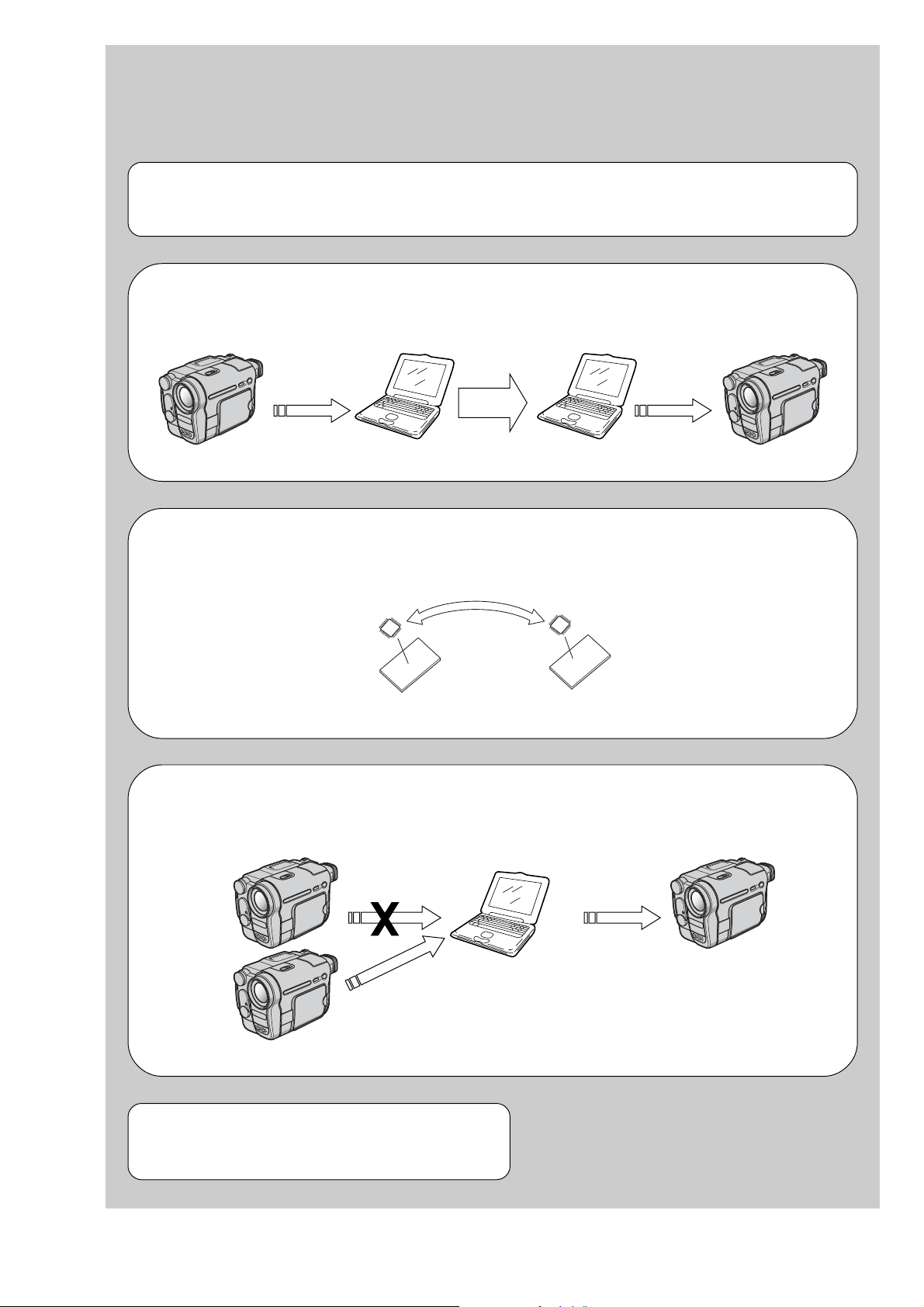
1. Before Starting Adjustments
(Machine before starting repair)
(Machine after a board is replaced)
PC PC
Save the EVR data
to a personal computer.
Download the saved
data to a machine.
EVR Data Re-writing Procedure When Replacing Board
The data that is stored in the repair board, is not necessarily correct.
Perform either procedure 1 or procedure 2 or procedure 3 when replacing board.
Procedure 1
Save the EVR data of the machine in which a board is going to be replaced. Download the saved data after a
board is replaced.
DCR-TRV360/TRV361/TRV460/TRV460E/TRV461E
SECTION 6
ADJUSTMENTS
Procedure 2
Remove the EEPROM from the board of the machine that is going to be repaired. Install the removed
EEPROM to the replaced board.
Remove the EEPROM and install it.
(Former board)
(New board)
Procedure 3
When the data cannot be saved due to defective EEPROM, or when the EEPROM cannot be removed or
installed, save the data from the same model of the same destination, and download it.
(Machine to be repaired) (Machine to be repaired)
PC
Download the data.
After the EVR data is saved and downloaded, chec k the
respective items of the EVR data.
(Refer to page 6-3 for the items to be checked)
Save the data.
(The same model of the same destination)
6-1

DCR-TRV360/TRV361/TRV460/TRV460E/TRV461E
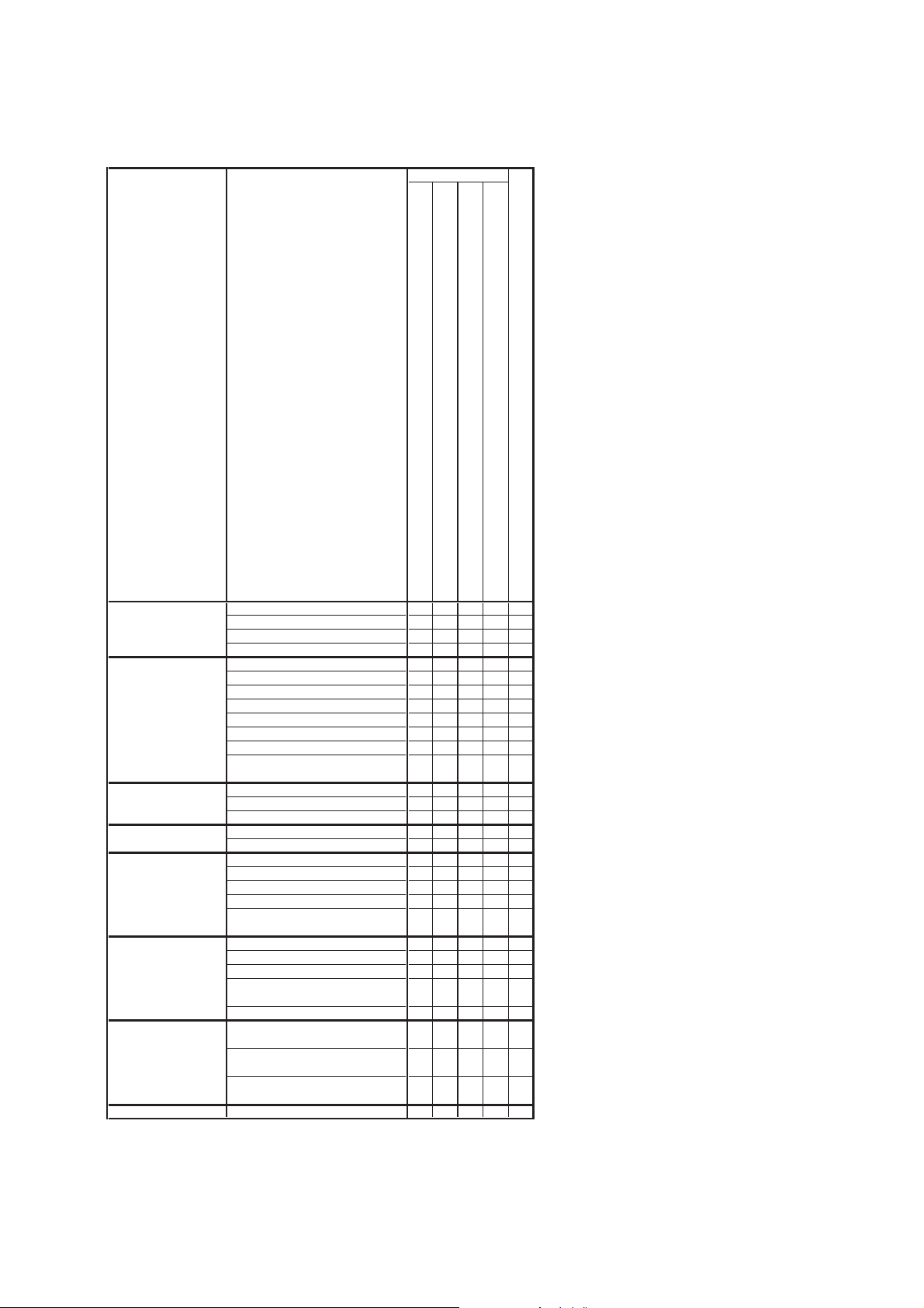
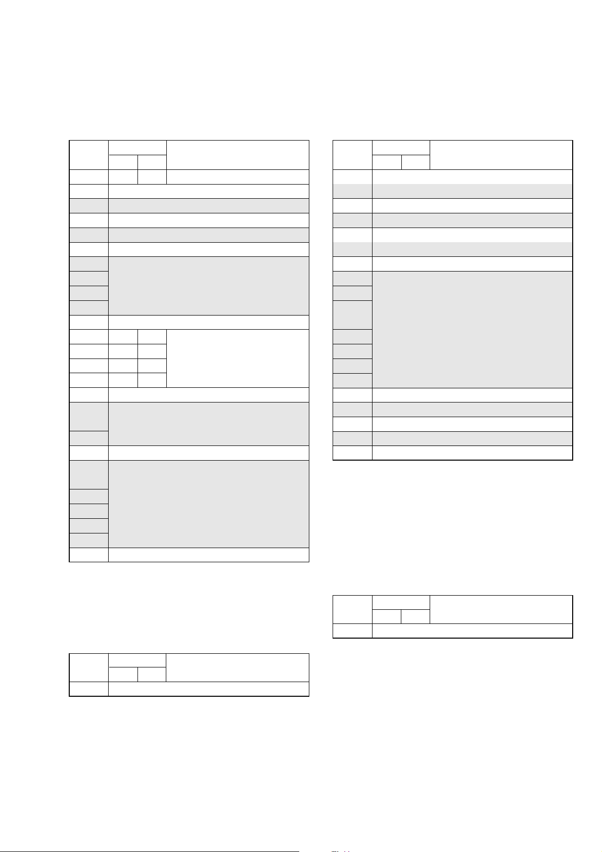
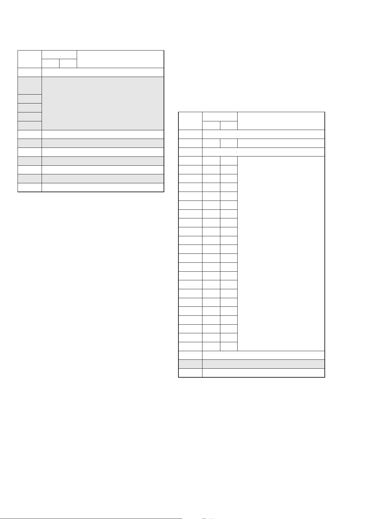
1-1. Adjusting Items when Replacing Main Parts and Boards
• Adjusting items when replacing main parts
When replacing main parts, adjust the items indicated by z in the following table.
Replaced part
Block replacement Mounted part replacement
Adjustment Section Adjustment
Initialization of 8, A, B,
C, D, E, F, 18, 1B, 1C, Initializing of B, 1B page data
1F page data Initializing of 8, C, 18, 1C page data
Camera HALL adj. z
LCD LCD level adj. z
System control Touch panel adj. zz
Servo, RF REEL FG adj. z
Video 27 MHz origin osillation adj. zz
Audio
Mechanism Tape path adj.
Initializing of A, D page data
Initializing of E, F, 1F page data
Flange back adj. zz
Optical axis adj. zz
Color reproduction adj. zz
LV standard data input zz
AWB standard data input zz
Auto white balance adj. zz
Angular velocity sensor output check
and steadyshot check
LCD V-COM adj. zz
LCD White balance adj.
Node uniqe ID No. input
CAP FG duty adj. zz
Digital8 switching position adj. zz
SD error rate check (LP) zz z
Hi8/Standard8 switching position adj.
(Note 3)
S VIDEO OUT Y level adj. zz
S VIDEO OUT C level adj. zz
Hi8/Standard8 Y/C output level setting
(Note 3)
Hi8/Standard8 AFC f
Hi8/Standard8 AFM BPF f
(Note 3)
Hi8/Standard8 AFM 1.5 MHz
deviation adj. (Note 3)
Hi8/Standard8 AFM 1.7 MHz
deviation adj. (Note 3)
0
adj. (Note 3)
0
adj.
(LCD panel)
(Fluorescent tube)
(Drum assembly) (Note 1)
(Capstan motor)
(CCD imager)
(YAW, PITCH sensor)
(Timing generator)
(S/H, AGC, A/D CONV.)
(Video/audio DSP, D/A Converter, Lens control)
(Hi8/Standard8 VTR process)
(DV signal process)
Lens device
Video light (Note 2)
LCD block LCD901
LCD block ND901
Mechanism deck (Note 1)
Mechanism deck M901
Mechanism deck M902
CD-472 board IC951
SI-041 board SE751/752
VC-345 board IC1501, X1501
VC-345 board IC1502
VC-345 board IC8001
VC-345 board IC2201
VC-345 board IC6001
z
zz z
zz
z
z
zzz
(Video in/out)
(EVR)
(Audio process)
(LCD driver)
VC-345 board IC3701
VC-345 board IC1601
VC-345 board IC5401
PD-205 board IC6001
z
z
z
Table 6-1-1 (1)
Note 1: When replacing the drum assy or mechanism deck, reset the data of page: 7, address: A7 to A9.
(Refer to “Record of Use Check” of “6-4. SERVICE MODE”)
Note 2: When replacing the video light, reset the data of page: 7, address: CE and CF.
(Refer to “Record of Use Check” of “6-4. SERVICE MODE”)
Note 3: DCR-TRV460/TRV460E/TRV461E only
6-2
DCR-TRV360/TRV361/TRV460/TRV460E/TRV461E
RadarW
RadarW
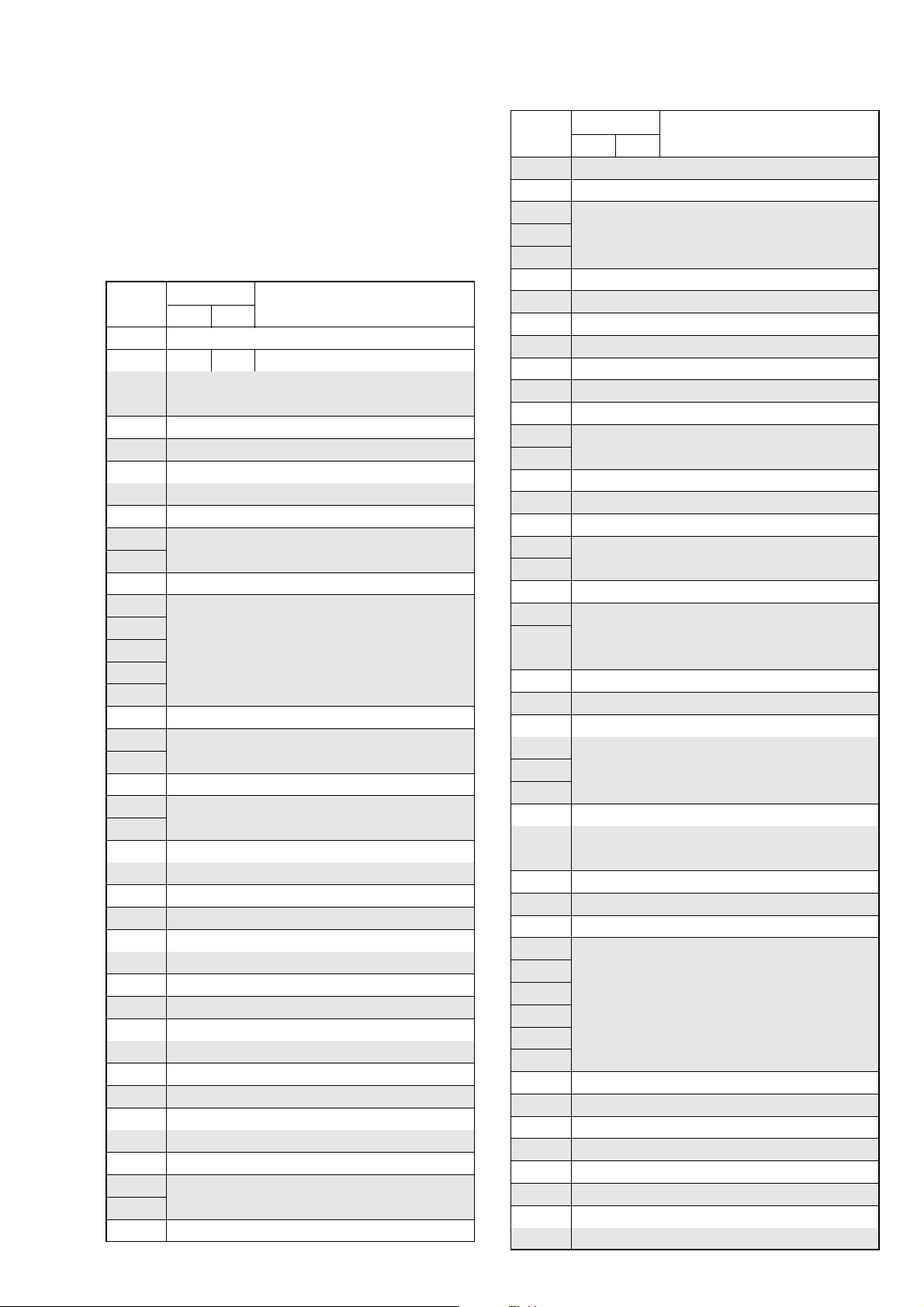
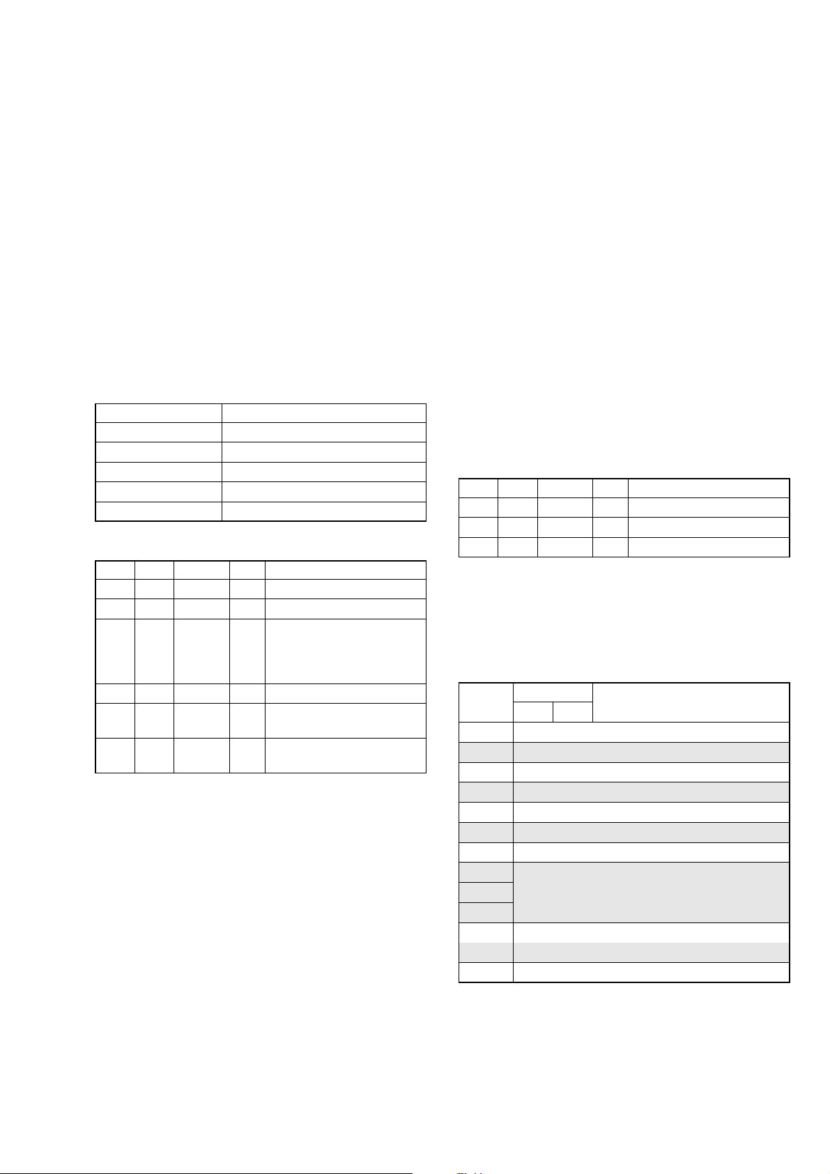
• Adjusting items when replacing a board or EEPROM
When replacing a board or EEPROM, adjust the items indicated by z in the following table.
Replaced part
Adjustment Section Adjustment
Initialization of 8, A, B,
C, D, E, F, 18, 1B, 1C, Initializing of B, 1B page data zz
1F page data Initializing of 8, C, 18, 1C page data zz
Camera HALL adj. zzz
LCD LCD level adj. zz zz
System control Touch panel adj. z
Servo, RF REEL FG adj. zzz
Video 27 MHz origin osillation adj. zz
Audio
Mechanism Tape path adj.
Initializing of A, D page data
Initializing of E, F, 1F page data
Flange back adj. zzz
Optical axis adj. zz
Color reproduction adj. zz
LV standard data input zzz
AWB standard data input zzz
Auto white balance adj. zzz
Angular velocity sensor output check
and steadyshot check
LCD V-COM adj. zz z
LCD White balance adj.
Node uniqe ID No. input
CAP FG duty adj. zzz
Digital8 switching position adj. zzz
SD error rate check (LP) zzz
Hi8/Standard8 switching position adj.
(Note 3)
S VIDEO OUT Y level adj. zz
S VIDEO OUT C level adj. zz
Hi8/Standard8 Y/C output level setting
(Note 3)
Hi8/Standard8 AFC f
Hi8/Standard8 AFM BPF f
(Note 3)
Hi8/Standard8 AFM 1.5 MHz
deviation adj. (Note 3)
Hi8/Standard8 AFM 1.7 MHz
deviation adj. (Note 3)
0
adj. (Note 3)
0
adj.
(COMPLETE)
(COMPLETE)
(EEPROM)
(EEPROM)
PD-205 board
VC-345 board
VC-345 board IC5702
zz
zz
zzz
zz z
zz
zz
zzz
zzz
zz
zz
zz
VC-345 board IC4502
RadarW
RadarW
RadarW
Supporting
Table 6-1-1 (2)
6-3
DCR-TRV360/TRV361/TRV460/TRV460E/TRV461E
6-1. CAMERA SECTION ADJUSTMENTS
1-1. PREPARATIONS BEFORE ADJUSTMENTS (CAMERA SECTION)
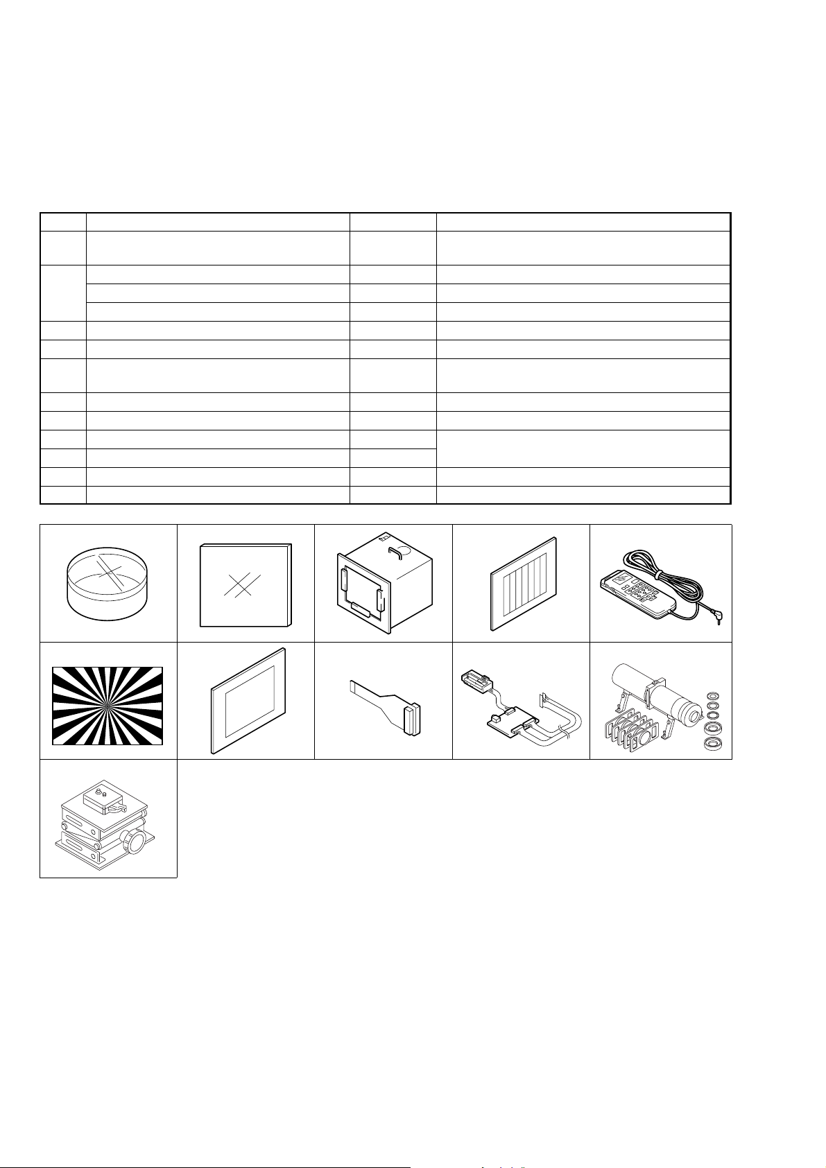
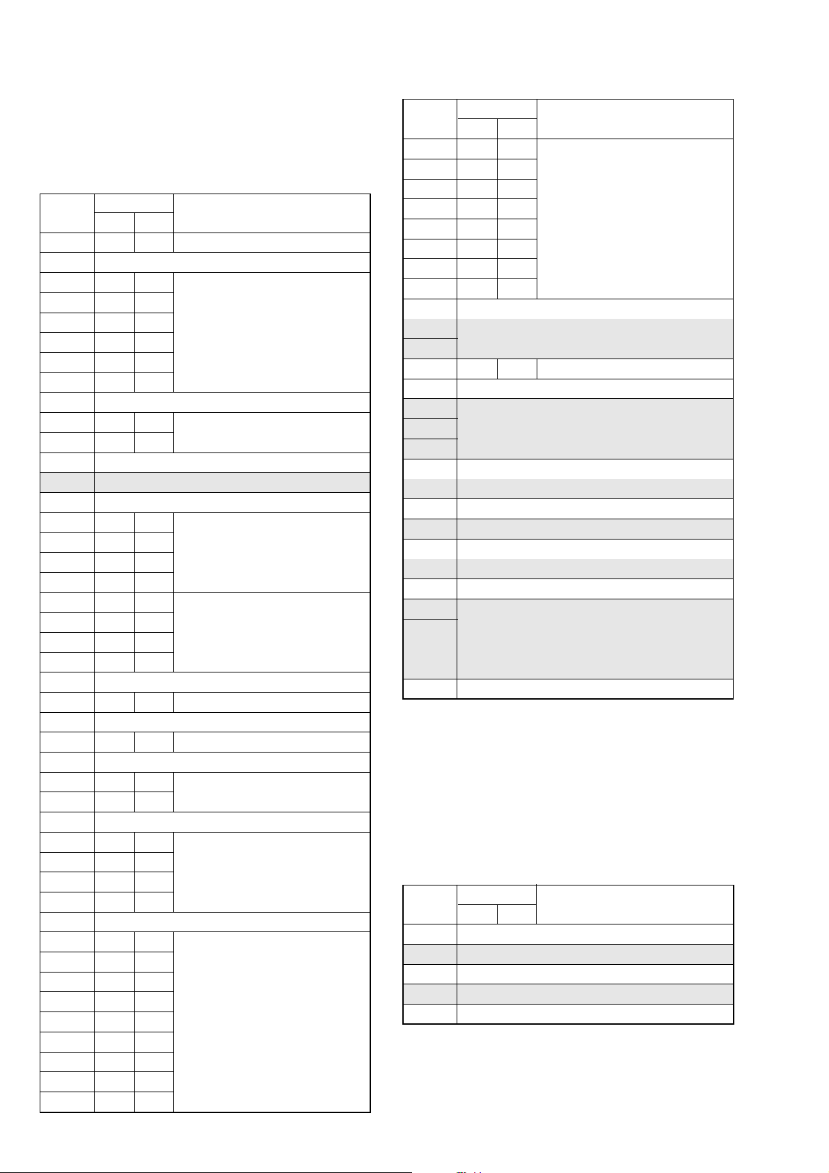
1-1-1. List of Service Tools
• Oscilloscope • Color monitor • Vectorscope
• Regulated power supply • Digital voltmeter • Frequency counter
Ref. No.
J-1
J-2
J-3
J-4
J-5
J-6
J-7
J-8
J-9
J-10
J-11
Filter for color temperature correction (C14)
ND filter 1.0
ND filter 0.4
ND filter 0.1
Pattern box PTB-450
Color chart for pattern box
Adjustment remote commander (RM-95 upgraded).
(Note)
Siemens star chart
Clear chart for pattern box
CPC jig connector
I/F unit for LANC control
Mini pattern box
Camera table
Name
Parts Code
J-6080-058-A
J-6080-808-A
J-6080-806-A
J-6080-807-A
J-6082-200-A
J-6020-250-A
J-6082-053-B
J-6080-875-A
J-6080-621-A
J-6082-539-A
J-6082-521-A
J-6082-353-B
J-6082-384-A
Auto white balance adjustment/check
White balance adjustment/check
White balance check
White balance check
White balance check
For checking the flange back
For adjusting the electronic viewfinder system
For adjusting the video section
For adjusting the flange back
For adjusting the flange back
Usage
J-1 J-2
J-6
J-11
J-7 J-8
J-3
J-4 J-5
J-9 J-10
Fig. 6-1-1
6-4
DCR-TRV360/TRV361/TRV460/TRV460E/TRV461E
CN1011
A/V OUT jack
16
1
Audio L (white)
Audio R (red)
Video (yellow)
TV monitor
AC IN
AC adaptor
AC adaptor
CPC lid
I/F unit for LANC control
(J-6082-521-A)
Conductor side
L serices Info
LITHIUM battery (7.2Vdc)
Adjustment
remote commander (RM-95)
CPC jig connector
(J-6082-539-A)
LANC jack
AC IN
Terminated at 75Ω
Vector scope
Screw (M2)
1-1-2. Preparations
Note: Before perform the adjustment, check that the data of page:
0, address: 10 is “00”.
If not, select page: 0, address: 10, and set data “00”.
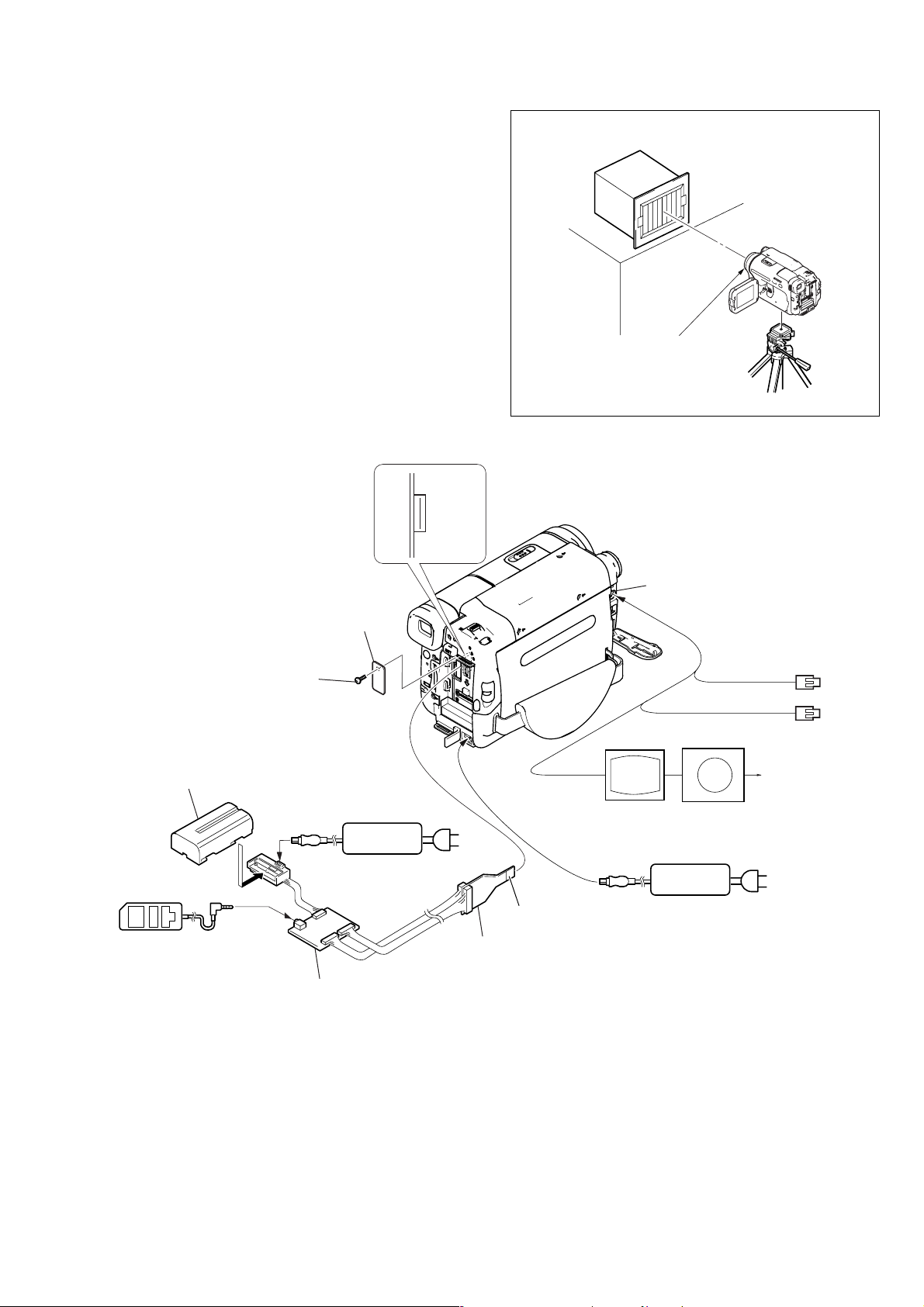
1) Connect the equipment for adjustments according to Fig. 6-1-
3.
2) Connect the adjustment remote commander to VC-345 board
CN1011 via I/F unit for LANC control (J-6082-521-A) and
CPC jig connector (J-6082-539-A). (Fig. 6-1-3)
To operate the adjustment remote commander, connect the AC
power adaptor to the DC IN jack of I/F unit for LANC control,
or connect the L series Info-LITHIUM battery to the battery
terminal of I/F unit for LANC control.
Pattern box
1 m
Front of the lens
Fig. 6-1-2
Fig. 6-1-3
6-5

DCR-TRV360/TRV361/TRV460/TRV460E/TRV461E
1-1-3. Precaution
1. Setting the Switch
Unless otherwise specified, set the switches as follows and perform adjustments without loading cassette.
1. POWER switch (SS-5100 block) .......................... CAMERA
2. FOCUS (MENU setting)...................................... MANUAL
3. BACK LIGHT (CF-5100 block) .................................... OFF
4. PROGRAM AE (MENU setting) ................................ AUTO
5. NIGHTSHOT PLUS switch (Lens block) ..................... OFF
6. EXPOSURE (MENU setting) ..................................... AUTO
7. PICT. EFFECT (MENU setting) .................................... OFF
2. Order of Adjustments
Basically carry out adjustments in the order given.
Color bar chart (Color reproduction adjustment frame)
H
Yellow
Cyan
Green
AB B
Fig. a
(VIDEO terminal of A/V jack
output waveform)
A=B
White
Magenta
Red
CD
Blue
A
Enlargement
C=D
Difference in level
8. D. EFFECT (MENU setting) ......................................... OFF
9. DIGITAL ZOOM (MENU setting) ................................ OFF
10. DEMO MODE (MENU setting) .................................... OFF
11. 16 : 9 WIDE (MENU setting) ........................................ OFF
12. COLOR SLOW S (MENU setting)................................ OFF
13. DISPLAY (MENU setting) .............................. LCD PANEL
Electronic beam scanning frame
Red
Cyan
White
Green
Yellow
V
Fig. b (monitor TV picture)
Magenta
Blue
CRT picture frame
B
A
Fig. 6-1-4
3. Subjects
1) Color bar chart (Color reproduction adjustment frame)
When performing adjustments using the color bar chart, adjust
the picture frame as shown in Fig. 6-1-4. (Color reproduction
adjustment frame)
2) Clear chart (Color reproduction adjustment frame)
Remove the color bar chart from the pattern box and insert a
clear chart in its place. (Do not perform zoom operations during
this time)
3) Chart for flange back adjustment
Join together a piece of white A0 size paper (1189mm × 841
mm) and a piece of black paper to make the chart shown in
Fig. 6-1-5.
Note: Use a non-reflecting and non-glazing vellum paper. The
size must be A0 or larger and the joint between the white
and black paper must not have any undulations.
Adjust the camera zoom and direction to
obtain the output wavef orm shown in Fig. a and
the monitor TV display shown in Fig. b.
White
841 mm
Black
1189 mm
Fig. 6-1-5
6-6
DCR-TRV360/TRV361/TRV460/TRV460E/TRV461E
1-2. INITIALIZATION OF 8, A, B, C, D, E, F, 18, 1B,
1C, 1F PAGE DATA
Note: If reading/writing data on pages 18, 1B, 1C, 1F, set data:
01 to page: 0, address: 10, and then select pages 8, B, C, F .
By this data setting, the pages 18, 1B, 1C, 1F can be selected.
After the data reading/writing finished, return the data on
page: 0, address: 10 to “00”.
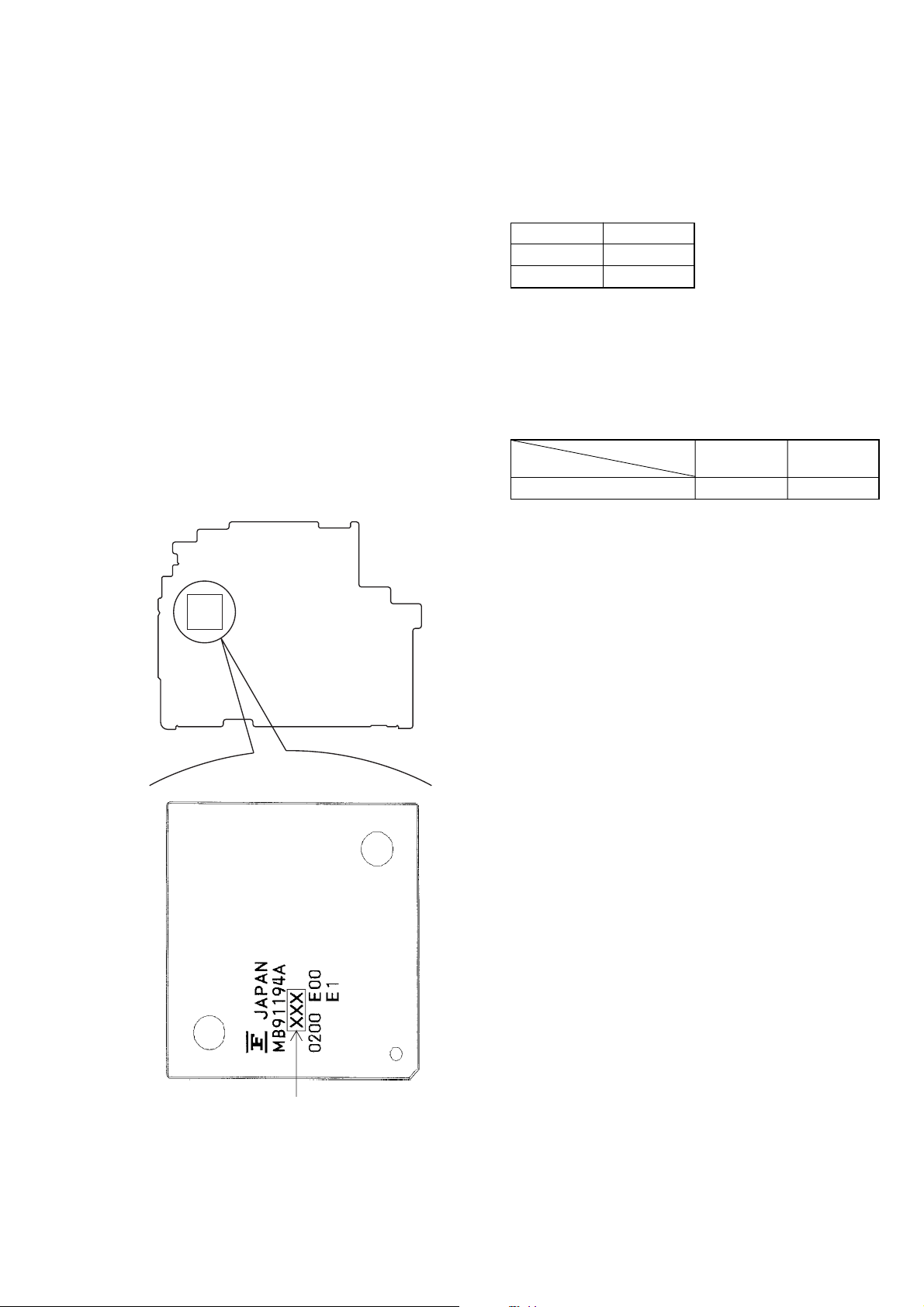
1-2-1. Version Check
Due to the change of IC4501 (mechanism control), there are two
types of versions A and B.
The EEPROM data are different according to respecti v e v ersions.
Also, the IC4501 version can be checked by a discrimination
method by the model name or by the adjusting remote commander.
Note 1: Changing the version does not make any changes in sche-
matic diagrams and the rest.
Note 2: Make it sure to confirm the version after replacing
IC4501.
1. Discrimination Method by the Model Name of
IC4501 (Mechanism Control)
VC-345 BOARD (SIDE B)
2. Discrimination Method by Adjusting Remote
Commander
Version check method:
1) Select page: 3, and address: FF.
2) The version of IC4501 can be checked from the displayed data.
Data Version
11 A
12 B
Data change method:
1) Select page: 0, address: 01, and set data: 01.
2) Select page: 1C, and input the data in the following table.
Note: To write in the non-volatile memory (EEPROM), press the
PAUSE button of the adjustment remote commander each
time to set the data.
3) Select page: 0, address: 01, and set data: 00.
Version
Address
D0 00 42
AB
IC4501
156 : A
164 : B
Fig. 6-1-6
6-7

DCR-TRV360/TRV361/TRV460/TRV460E/TRV461E
1-2-2. Initialization of A, B, D, 1B Page Data
Note: Check that the data of page: 0, address: 10 is “00”.
1. Initializing the A, B, D, 1B Page Data
Note 1: If “Initialization of Pages A, B, D, 1B” is executed, all
data on pages A, B, D, 1B are initialized. (Only an individual page cannot be initialized)
Note 2: If the A, B, D, 1B page data has been initialized, the
following adjustments need to be performed again.
1) Modification of A, B, D, 1B page data
Note 3: NTSC model: DCR-TRV360/TRV361/TRV460
PAL model: DCR-TRV460E/TRV461E
Adjustment Page A
Adjustment Address 10 to FF
Adjustment Page B
Adjustment Address 00 to FF
Adjustment Page D
Adjustment Address 10 to FF
Adjustment Page 1B
Adjustment Address 00 to FF
Initializing method:
Order Page Address Data Procedure
10 0101
20 1000
Set the following data
37 04
47 0128
57 00 01 Press PAUSE button.
67 02
7
00: NTSC model
01: PAL model
Check the data changes to
“01”.
Perform “Modification of A,
B, D, 1B Page Data”
2. Modification of A, B, D, 1B Page Data
If the A, B, D, 1B page data has been initialized, change the data
of the“Fixed data-2” address shown in the following table by
manual input.
Modifying method:
1) Before changing the data, select page: 0, address: 01, and set
data: 01.
2) New data for changing are not shown in the tables because
they are different in destination. When changing the data, cop y
the data built in the same model.
Note 1: If copy the data built in the different model, the
camcorder may not operate.
3) When changing the data, press the PAUSE button of the adjustment remote commander each time when setting new data
to write the data in the non-volatile memory.
4) Check that the data of adjustment addresses is the initial value.
If not, change the data to the initial value.
Processing after completing modification A, B, D, 1B page
data:
Order Page Address Data Procedure
10 1000
22 0029
32 01 29 Press PAUSE button.
Note 2: If the following symptoms occur after completing of
the“Modification A, B, D, 1B page data”, check that the
data of the “Fixed data-2” addresses of A, B, D, 1B page
are same as those of the same model of the same destination.
1) The power is shut off so that unit cannot operate.
6-8
DCR-TRV360/TRV361/TRV460/TRV460E/TRV461E
3. A Page Table
Note 1: Check that the data of page: 0, address: 10 is “00”.
Note 2: Fixed data-1: Initialized data. (Refer to “1. Initializing
the A, B, D, 1B Page Data”)
Fixed data-2: Modified data. (Refer to “2. Modification
of A, B, D, 1B Page Data”)
Address
10 00 00 Test mode
11 to 1B Fixed data-1 (Initialized data)
1C Fixed data-2
1D to 30 Fixed data-1 (Initialized data)
31 Fixed data-2
32 to 50 Fixed data-1 (Initialized data)
51
52
53
54
55 to 8F Fixed data-1 (Initialized data)
90 DB D2
91 25 1D
92 EA C6
93 1A 24
94 to CF Fixed data-1 (Initialized data)
D0
D1 Fixed data-2
D2
D3 Fixed data-1 (Initialized data)
D4
D5
D6
D7
D8
D9
DA to FF Fixed data-1 (Initialized data)
4. B Page Table
Note 1: Check that the data of page: 0, address: 10 is “00”.
Note 2: Fixed data-1: Initialized data. (Refer to “1. Initializing
Address
00 to FF Fixed data-1 (Initialized data)
Initial value
NTSC PAL
Fixed data-2
Touch panel adj.
Fixed data-2
the A, B, D, 1B Page Data”)
Fixed data-2: Modified data. (Refer to “2. Modification
of A, B, D, 1B Page Data”)
Initial value
NTSC PAL
Remark
Remark
5. D Page Table
Note 1: Check that the data of page: 0, address: 10 is “00”.
Note 2: Fixed data-1: Initialized data. (Refer to “1. Initializing
the A, B, D, 1B Page Data”)
Fixed data-2: Modified data. (Refer to “2. Modification
of A, B, D, 1B Page Data”)
Address
10 to 13 Fixed data-1 (Initialized data)
14 Fixed data-2
15 Fixed data-1 (Initialized data)
16 Fixed data-2
17 to 19 Fixed data-1 (Initialized data)
1A Fixed data-2
1B to 27 Fixed data-1 (Initialized data)
28
29
2A
2B
2C
2D
2E
2F
30 to 32 Fixed data-1 (Initialized data)
33 Fixed data-2
34 to 56 Fixed data-1 (Initialized data)
57 Fixed data-2
58 to FF Fixed data-1 (Initialized data)
6. 1B Page Table
Note 1: If reading/writing data on pages 1B, set data: 01 to page:
Note 2: Fixed data-1: Initialized data. (Refer to “1. Initializing
Address
00 to FF Fixed data-1 (Initialized data)
Initial value
NTSC PAL
Fixed data-2
0, address: 10, and then select pages B. By this data setting, the pages 1B can be selected.
After the data reading/writing finished, return the data
on page: 0, address: 10 to “00”.
the A, B, D, 1B Page Data”)
Fixed data-2: Modified data. (Refer to “2. Modification
of A, B, D, 1B Page Data”)
Initial value
NTSC PAL
Remark
Remark
6-9

DCR-TRV360/TRV361/TRV460/TRV460E/TRV461E
1-2-3. Initialization of 8, C, 18, 1C Page Data
Note: If reading/writing data on pages 18, 1C, set data: 01 to
page: 0, address: 10, and then select pages 8, C. By this
data setting, the pages 18, 1C can be selected.
After the data reading/writing finished, return the data on
page: 0, address: 10 to “00”.
1. Initializing the 8, C, 18, 1C Page Data
Note 1: If “Initialization of Pages 8, C, 18, 1C” is executed, all
data on pages 8, C, 18, 1C are initialized. (Only an individual page cannot be initialized)
Note 2: If the 8, C, 18, 1C page data has been initialized, the
following adjustments need to be performed again.
1) Modification of 8, C, 18, 1C page data
2) Electronic viewfinder system adjustments
3) LCD system adjustments
4) Node unique ID No. input
5) Servo, RF system adjustments
6) “S VIDEO OUT Y Le vel Adjustment” and “S VIDEO
OUT C Level Adjustment” of the video system adjustments
7) Audio system adjustments
Adjustment Page 8
Adjustment Address 00 to FF
Adjustment Page C
Adjustment Address 10 to FF
Adjustment Page 18
Adjustment Address 00 to FF
Adjustment Page 1C
Adjustment Address 00 to FF
2. Modification of 8, C, 18, 1C Page Data
If the 8, C, 18, 1C page data has been initialized, change the data
of the “Fixed data-2” address shown in the following table by
manual input.
Modifying method:
1) Before changing the data, select page: 0, address: 01, and set
data: 01.
2) If modification of data on pages 8, C, set data: 00 to page: 0,
address: 10, and then select pages 8, C.
3) If modification of data on pages 18, 1C, set data: 01 to page:
0, address: 10, and then select pages 8, C. After the modification of data finished, return the data on page: 0, address: 10 to
“00”.
4) New data for changing are not shown in the tables because
they are different in destination. When changing the data, cop y
the data built in the same model.
Note: If copy the data built in the different model, the
camcorder may not operate.
5) When changing the data, press the PAUSE button of the adjustment remote commander each time when setting new data
to write the data in the non-volatile memory.
6) Check that the data of adjustment addresses is the initial value.
If not, change the data to the initial value.
Processing after completing modification 8, C, 18, 1C page
data:
Order Page Address Data Procedure
10 1000
22 0029
32 01 29 Press PAUSE button.
Initializing method:
Order Page Address Data Procedure
10 0101
20 1000
33 8110
43 80 0C Press PAUSE button.
53 80
6
Check the data changes to
“1C”.
Perform “Modification of 8,
C, 18, 1C Page Data”
6-10

DCR-TRV360/TRV361/TRV460/TRV460E/TRV461E
3. 8 Page Table
Note 1: Check that the data of page: 0, address: 10 is “00”.
Note 2: Fixed data-1: Initialized data. (Refer to “1. Initializing
the 8, C, 18, 1C Page Data”)
Fixed data-2: Modified data. (Refer to “2. Modification
of 8, C, 18, 1C Page Data”)
Address
00 to 29 Fixed data-1 (Initialized data)
2A Fixed data-2
2B to 79 Fixed data-1 (Initialized data)
7A Fixed data-2
7B to AB Fixed data-1 (Initialized data)
AC Fixed data-2
AD to BD Fixed data-1 (Initialized data)
BE Fixed data-2
BF to C2 Fixed data-1 (Initialized data)
C3
C4 Fixed data-2
C5
C6, C7 Fixed data-1 (Initialized data)
C8
C9
CA
CB
CC Fixed data-1 (Initialized data)
CD Fixed data-2
CE to D5 Fixed data-1 (Initialized data)
D6
D7
D8 to FF Fixed data-1 (Initialized data)
Initial value
NTSC PAL
Remark
Fixed data-2
Fixed data-2
6-11

DCR-TRV360/TRV361/TRV460/TRV460E/TRV461E
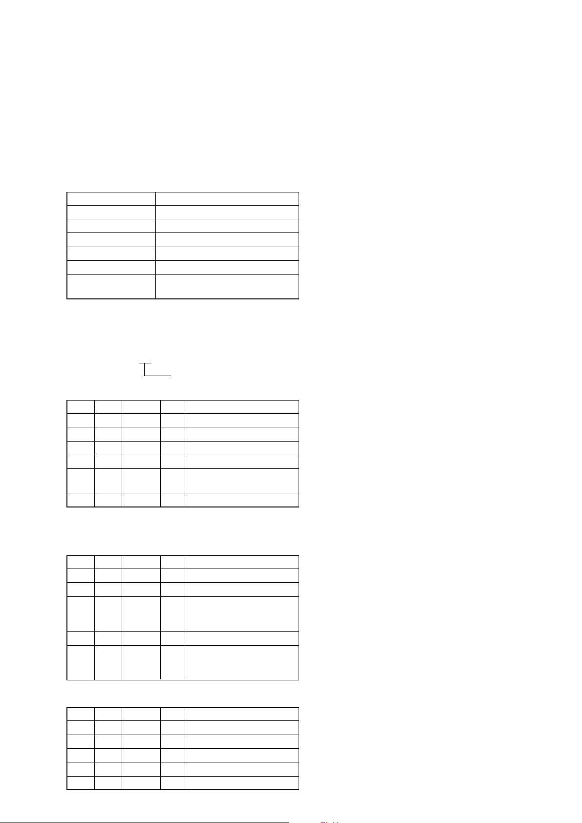
4. C Page Table
Note 1: Check that the data of page: 0, address: 10 is “00”.
Note 2: Fixed data-1: Initialized data. (Refer to “1. Initializing
the 8, C, 18, 1C Page Data”)
Fixed data-2: Modified data. (Refer to “2. Modification
of 8, C, 18, 1C Page Data”)
Address
10 EE EE
11 00 00
12 00 00
13 00 00
14, 15 Fixed data-1 (Initialized data)
16 E0 E0 CAP FG duty adj.
17 E0 E0 REEL FG adj.
18 to 24 Fixed data-1 (Initialized data)
25 80 80 S VIDEO OUT Y level adj.
26 70 70
27 50 50
28 to 2E Fixed data-1 (Initialized data)
2F 0E 0E REEL FG adj.
30, 31 Fixed data-1 (Initialized data)
32 0A 0A
33 00 00
34 30 30 Hi8/Standard8 AFC f0 adj.
35 A0 A0
36 AA AA
37 Fixed data-1 (Initialized data)
38 A6 A6
39 94 94
3A 80 80 Hi8/Standard8 AFM BPF f0 adj.
3B to 4E Fixed data-1 (Initialized data)
4F Fixed data-2
50 85 85
51 8F 8F
52 90 90 LCD V -COM adj.
53 A2 A2 LCD level adj. (RGB AMP adj.)
54, 55 Fixed data-1 (Initialized data)
56 7A 7A
57 5F 5F
58 2E 2E LCD level adj. (Contrast adj.)
59
5A
5B C0 C0 LCD level adj. (PSIG black adj.)
5C to 65 Fixed data-1 (Initialized data)
66 Fixed data-2
67 to 71 Fixed data-1 (Initialized data)
72 Fixed data-2
73, 74 Fixed data-1 (Initialized data)
75 Fixed data-2
76 to AC Fixed data-1 (Initialized data)
AD Fixed data-2
Initial value
NTSC PAL
Remark
Digital8 switching position adj.
S VIDEO OUT C level adj.
Hi8/Standard switching position adj.
Hi8/Standard8 Y/C output level setting
Hi8/Standard8 AFM 1.5 MHz deviation adj.
Hi8/Standard8 AFM 1.7 MHz deviation adj.
LCD level adj. (VCO adj.)
LCD White balance adj.
Fixed data-2
Address
AE to D2 Fixed data-1 (Initialized data)
D3 Fixed data-2
D4 Fixed data-1 (Initialized data)
D5
D6
D7 Fixed data-1 (Initialized data)
D8
D9
DA
DB
DC to DE Fixed data-1 (Initialized data)
DF Fixed data-2
E0 08 08
E1 00 00
E2 46 46
E3 01 01
E4 02 02
E5 00 00
E6 00 00
E7 00 00
E8 to F3 Fixed data-1 (Initialized data)
FA 00 00
FB 00 00
FC 00 00
FD 00 00
FE 00 00
FF 00 00
Initial value
NTSC PAL
F4 00 00
F5 00 00
F6 00 00
F7 00 00
F8 00 00
F9 00 00
Remark
Fixed data-2
Fixed data-2
Node unique ID No. input
Emergency memory
6-12
DCR-TRV360/TRV361/TRV460/TRV460E/TRV461E
5. 18 Page Table
Note 1: If reading/writing data on page 18, set data: 01 to page:
0, address: 10, and then select page 8. By this data setting, the page 18 can be selected.
After the data reading/writing finished, return the data
on page: 0, address: 10 to “00”.
Note 2: Fixed data-1: Initialized data. (Refer to “1. Initializing
the 8, C, 18, 1C Page Data”)
Fixed data-2: Modified data. (Refer to “2. Modification
of 8, C, 18, 1C Page Data”)
Address
00 to 11 Fixed data-1 (Initialized data)
12 00 00 Test mode (Hi8/Standard8 mode)
13
14
15 Fixed data-1 (Initialized data)
16 Fixed data-2
17 to 1B Fixed data-1 (Initialized data)
1C Fixed data-2
1D, 1E Fixed data-1 (Initialized data)
1F
20
21 Fixed data-1 (Initialized data)
22
23
24 Fixed data-2
25
26
27 Fixed data-1 (Initialized data)
28
29
2A, 2B Fixed data-1 (Initialized data)
2C
2D
2E, 2F Fixed data-1 (Initialized data)
30 Fixed data-2
31, 32 Fixed data-1 (Initialized data)
33 Fixed data-2
34 Fixed data-1 (Initialized data)
35 Fixed data-2
36 Fixed data-1 (Initialized data)
37 Fixed data-2
38 to 3A Fixed data-1 (Initialized data)
3B Fixed data-2
3C to 3E Fixed data-1 (Initialized data)
3F Fixed data-2
40 to 51 Fixed data-1 (Initialized data)
52 Fixed data-2
53 Fixed data-1 (Initialized data)
54
55
56 to 58 Fixed data-1 (Initialized data)
Initial value
NTSC PAL
Remark
Fixed data-2
Fixed data-2
Fixed data-2
Fixed data-2
Fixed data-2
Address
59 Fixed data-2
5A, 5B Fixed data-1 (Initialized data)
5C
5D Fixed data-2
5E
5F Fixed data-1 (Initialized data)
60 Fixed data-2
61, 62 Fixed data-1 (Initialized data)
63 Fixed data-2
64 to 67 Fixed data-1 (Initialized data)
68 Fixed data-2
69 to 6D Fixed data-1 (Initialized data)
6E
6F
70 to 74 Fixed data-1 (Initialized data)
75 Fixed data-2
76 Fixed data-1 (Initialized data)
77
78
79 Fixed data-1 (Initialized data)
7A
7B Fixed data-2
7C
7D Fixed data-1 (Initialized data)
7E Fixed data-2
7F Fixed data-1 (Initialized data)
80
81 Fixed data-2
82
83, 84 Fixed data-1 (Initialized data)
85
86
87 Fixed data-1 (Initialized data)
88 Fixed data-2
89 Fixed data-1 (Initialized data)
8A
8B
8C
8D
8E
8F
90 Fixed data-1 (Initialized data)
91 Fixed data-2
92 Fixed data-1 (Initialized data)
93 Fixed data-2
94 Fixed data-1 (Initialized data)
95 Fixed data-2
96 Fixed data-1 (Initialized data)
97 Fixed data-2
Initial value
NTSC PAL
Remark
Fixed data-2
Fixed data-2
Fixed data-2
Fixed data-2
6-13
DCR-TRV360/TRV361/TRV460/TRV460E/TRV461E
18 Page Table
Address
98 to 9D Fixed data-1 (Initialized data)
9E
9F
A0
A1
A2
A3
A4 to AF Fixed data-1 (Initialized data)
B0 Fixed data-2
B1 to B6 Fixed data-1 (Initialized data)
B7 Fixed data-2
B8, B9 Fixed data-1 (Initialized data)
BA Fixed data-2
BB to FF Fixed data-1 (Initialized data)
Initial value
NTSC PAL
Remark
Fixed data-2
6. 1C Page Table
Note 1: If reading/writing data on page 1C, set data: 01 to page:
0, address: 10, and then select page C. By this data setting, the page 1C can be selected.
After the data reading/writing finished, return the data
on page: 0, address: 10 to “00”.
Note 2: Fixed data-1: Initialized data. (Refer to “1. Initializing
the 8, C, 18, 1C Page Data”)
Fixed data-2: Modified data. (Refer to “2. Modification
of 8, C, 18, 1C Page Data”)
Address
00 to 08 Fixed data-1 (Initialized data)
0A to B2 Fixed data-1 (Initialized data)
B3 00 00
B4 00 00
B5 00 00
B6 00 00
B7 00 00
B8 80 80
B9 00 00
BA 00 00
BB 00 00
BC 00 00
BD 00 00
BE 00 00
BF 00 00
C0 00 00
C1 00 00
C2 00 00
C3 80 80
C4 00 00
C5 00 00
C6 00 00
C7 00 00
C8 00 00
C9 to CF Fixed data-1 (Initialized data)
D0 Fixed data-2
D1 to FF Fixed data-1 (Initialized data)
Initial value
NTSC PAL
09 FF FF Test mode (Digital8 mode)
SD error rate check (LP)
Remark
6-14
DCR-TRV360/TRV361/TRV460/TRV460E/TRV461E
1-2-4. Initialization of E, F, 1F Page Data
Note: If reading/writing data on page 1F , set data: 01 to page: 0,
address: 10, and then select page F. By this data setting,
the page 1F can be selected.
After the data reading/writing finished, return the data on
page: 0, address: 10 to “00”.
1. Initializing the E, F, 1F Page Data
Note 1: If “Initialization of Pages E, F, 1F” is executed, all data
on pages E, F , 1F are initialized. (Only an individual page
cannot be initialized)
Note 2: If the E, F, 1F page data has been initialized, the follow-
ing adjustments need to be performed again.
1) Modification of E, F, 1F page data
2) “27 MHz Origin Oscillation Adjustment”, “Hi8/Standard8 Y/C Output Level Setting” and “Hi8/Standar d8
AFC f
Adjustment” of the video system adjustment.
0
3) Camera system adjustments
Note 3: NTSC model: DCR-TRV360/TRV361/TRV460
PAL model: DCR-TRV460E/TRV461E
Adjustment Page E
Adjustment Address 00 to FF
Adjustment Page F
Adjustment Address 10 to FF
Adjustment Page 1F
Adjustment Address 00 to FF
Initializing method:
Order Page Address Data Procedure
10 0101
20 1000
Set the following data, and
36 01
46 03 01 Press PAUSE button.
56 02
6
press PAUSE button.
2D: NTSC model
2F: PAL model
Check the data changes to
“01”.
Perform “Modification of E,
F, 1F Page Data”
2. Modification of E, F, 1F Page Data
If the E, F, 1F page data has been initialized, change the data of
the “Fixed data-2” address shown in the following table by manual
input.
Modifying method:
1) Before changing the data, select page: 0, address: 01, and set
data: 01.
2) If modification of data on pages E, F, set data: 00 to page: 0,
address: 10, and then select pages E, F.
3) If modification of data on page 1F, set data: 01 to page: 0,
address: 10, and then select page F. After the modification of
data finished, return the data on page: 0, address: 10 to “00”.
4) New data for changing are not shown in the tables because
they are different in destination. When changing the data, copy
the data built in the same model.
Note: If copy the data built in the different model, the
camcorder may not operate.
5) When changing the data, press the PAUSE button of the adjustment remote commander each time when setting new data
to write the data in the non-volatile memory.
6) Check that the data of adjustment addresses is the initial value.
If not, change the data to the initial value.
Processing after completing modification E, F, 1F page data:
Order Page Address Data Procedure
10 1000
22 0029
32 01 29 Press PAUSE button.
3. E Page Table
Note 1: Check that the data of page: 0, address: 10 is “00”.
Note 2: Fixed data-1: Initialized data. (Refer to “1. Initializing
the E, F, 1F Page Data”)
Fixed data-2: Modified data. (Refer to “2. Modification
of E, F, 1F Page Data”)
Address
00 to 0F Fixed data-1 (Initialized data)
10 Fixed data-2
11 to 1D Fixed data-1 (Initialized data)
1E Fixed data-2
1F, 20 Fixed data-1 (Initialized data)
21 Fixed data-2
22 to B0 Fixed data-1 (Initialized data)
B1
B2 Fixed data-2
B3
B4 to E3 Fixed data-1 (Initialized data)
E4 Fixed data-2
E5 to FF Fixed data-1 (Initialized data)
Initial value
NTSC PAL
Remark
6-15
DCR-TRV360/TRV361/TRV460/TRV460E/TRV461E
4. F Page Table
Note 1: Check that the data of page: 0, address: 10 is “00”.
Note 2: Fixed data-1: Initialized data. (Refer to “1. Initializing
the E, F, 1F Page Data”)
Fixed data-2: Modified data. (Refer to “2. Modification
of E, F, 1F Page Data”)
Address
10 80 80 27 MHz origin osillation adj.
11 Fixed data-1 (Initialized data)
12 4A 4A
13 56 56
14 11 11
15 20 20
16 02 02
17 E0 E0
18, 19 Fixed data-1 (Initialized data)
1A 00 00
1B 60 60
1C to 26 Fixed data-1 (Initialized data)
27 Fixed data-2
28, 29 Fixed data-1 (Initialized data)
2A 1B 1B
2B 00 00
2C 07 07
2D 00 00
2E 0E 0E
2F 00 00
30 0D 0D
31 00 00
32 Fixed data-1 (Initialized data)
33 22 22 Color reproduction adj.
34 Fixed data-1 (Initialized data)
35 27 24 Color reproduction adj.
36 to 39 Fixed data-1 (Initialized data)
3A 00 00
3B F1 EF
3C, 3D Fixed data-1 (Initialized data)
3E 2A 2B
3F C0 00
40 59 59
41 00 40
42, 43 Fixed data-1 (Initialized data)
44 28 28
45 EC EC
46 35 35
47 8F 8F
48 13 13
49 B8 B8
4A 00 00
4B 00 00
4C 00 00
Initial value
NTSC PAL
Remark
Hall adj.
LV standard data input
Auto white balance
standard data input
Auto white balance adj.
Color reproduction adj.
Auto white balance adj.
Flange back adj.
Address
4D 00 00
4E 2B 2B
55 to 57 Fixed data-1 (Initialized data)
5A FF FF Optical axis adj.
5B to 8D Fixed data-1 (Initialized data)
8E
91 to 96 Fixed data-1 (Initialized data)
98, 99 Fixed data-1 (Initialized data)
9A Fixed data-2
9B to A3 Fixed data-1 (Initialized data)
A4 Fixed data-2
A5 to E9 Fixed data-1 (Initialized data)
EA
EB
EC
ED
EE to FF Fixed data-1 (Initialized data)
5. 1F Page Table
Note 1: If reading/writing data on pages 1F, set data: 01 to page:
Note 2: Fixed data-1: Initialized data. (Refer to “1. Initializing
Address
00 to 52 Fixed data-1 (Initialized data)
54 to D0 Fixed data-1 (Initialized data)
D1 Fixed data-2
D2 to FF Fixed data-1 (Initialized data)
Initial value
NTSC PAL
4F 19 19
50 00 00
51 32 32
52 04 04
53 00 00
54 00 00
58
59
8F Fixed data-2
90
97 Fixed data-2
0, address: 10, and then select pages F. By this data setting, the pages 1F can be selected.
After the data reading/writing finished, return the data
on page: 0, address: 10 to “00”.
the E, F, 1F Page Data”)
Fixed data-2: Modified data. (Refer to “2. Modification
of E, F, 1F Page Data”)
Initial value
NTSC PAL
53 Fixed data-2
Flange back adj.
Fixed data-2
Fixed data-2
Remark
Remark
6-16
DCR-TRV360/TRV361/TRV460/TRV460E/TRV461E
1-3. CAMERA SYSTEM ADJUSTMENTS
Before perform the camera system adjustments, check that the
specified values of “27 MHz Origin Oscillation Adjustment”, “S
VIDEO OUT Y Level Adjustment” and “S VIDEO OUT C Level
Adjustment” of “VIDEO SYSTEM ADJUSTMENT” are satisf ied.
Check that the data of page: 0, address: 10, is “00”.
If not, select page: 0, address: 10, and set data “00”
1. HALL Adjustment
For detecting the position of lens iris, adjust the hall AMP gain
and offset.
Mode CAMERA
Subject Not required
Measurement Point Displayed data of page: 1 (Note 3)
Measuring Instrument Adjusting remote commander
Adjustment Page F
Adjustment Address 12 to 17
Specified value 87 to 8B during IRIS OPEN
Note 1: Check that the data of page: 0, address: 10 is “00”.
Note 2: Check that the data of page: 6, address: 02 is “00”.
If not, turn the power of unit OFF/ON.
Note 3: The right two digits of the page: 1 displayed data of the
adjusting remote commander.
1:00:
Adjusting method:
Order Page Address Data Procedure
10 0101
26 9489
36 9517
46 01 6D Press PAUSE button. (Note 4)
56 02
66 01 00 Press PAUSE button.
Note 4: The adjustment data will be automatically input to page:
F, address: 12 to 17.
RadarWRadarWRadarW
15 to 19 during IRIS CLOSE
XX
Displayed data
Check the data changes to
“01”.
Checking method:
Order Page Address Data Procedure
10 0303
26 01 01 Press PAUSE button.
Check that the displayed data
31
46 01 03 Press PAUSE button.
51
Processing after completing adjustment:
Order Page Address Data Procedure
16 01 00 Press PAUSE button.
26 9400
36 9500
40 0300
50 0100
(Note 3) during IRIS OPEN
satisfied the specified value.
Check that the displayed data
(Note 3) during IRIS CLOSE
satisfied the specified value.
6-17
DCR-TRV360/TRV361/TRV460/TRV460E/TRV461E
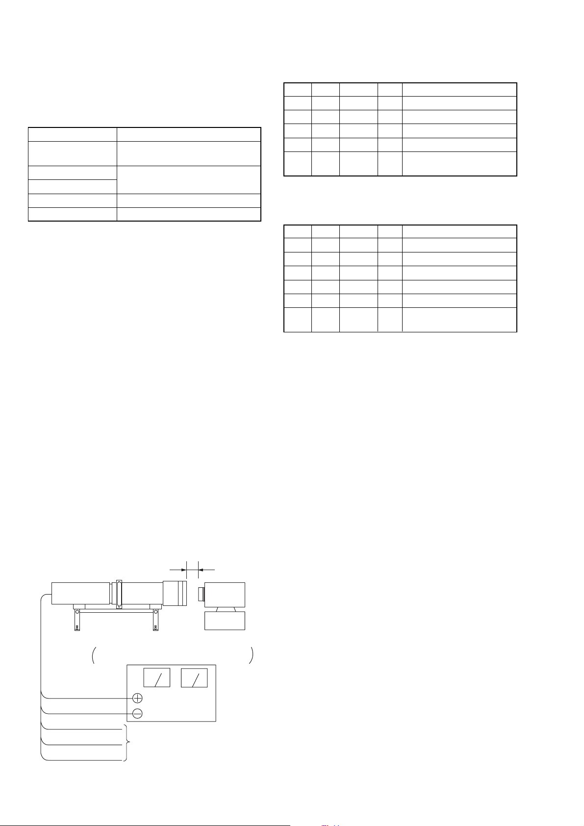
2. Flange Back Adjustment
RadarWRadarWRadarW
(Using the Minipattern Box)
The inner focus lens flange back adjustment is carried out
automatically. In whichever case, the focus will be deviated during auto focusing/manual focusing.
Mode CAMERA
Subject Siemens star chart with ND filter for
minipattern box (Note 1)
Measurement Point Check operation on monitor TV
Measuring Instrument
Adjustment Page F
Adjustment Address 44 to 54
Note 1: Dark Siemens star chart.
Note 2: Check that the data of page: 0, address: 10 is “00”.
Note 3: Check that the data of page: 6, address: 02 is “00”.
If not, turn the power of unit OFF/ON.
Note 4: Perform the adjustment with the camcorder in horizon-
tal state.
Note 5: Perform “HALL Adjustment” before this adjustment.
Switch setting:
1) NIGHTSHOT PLUS........................................................ OFF
2) DISPLAY (Menu setting) ................................. LCD PANEL
Preparations before adjustments:
1) The minipattern box is installed as shown in the following f igure.
Note 6: The attachment lenses are not used.
2) Install the minipattern box so that the distance between it and
the front of lens of camcorder is less than 3 cm.
3) Make the height of minipattern box and the camera equal.
4) Check the output voltage of the regulated power supply is the
specified voltage ± 0.01 Vdc.
5) Check that the center of Siemens star chart meets the center of
shot image screen with the zoom lens at TELE end and WIDE
end respectively.
Adjusting method:
Order Page Address Data Procedure
10 0101
26 4801
36 01 13 Press PAUSE button.
46 01 27 Press PAUSE button. (Note 7)
56 02
Check the data changes to
“01”.
Note 7: The adjustment data will be automatically input to page:
F, address: 44 to 54.
Processing after completing adjustment:
Order Page Address Data Procedure
16 01 00 Press PAUSE button.
26 01 25 Press PAUSE button.
36 01 00 Press PAUSE button.
46 4800
50 0100
6
Perform “Flange Back
Check”.
Specified voltage: The specified voltage varies according to the
minipattern box, so adjust the power supply
output voltage to the specified voltage written
on the sheet which is supplied with the
minipattern box.
Below 3 cm
Minipattern box
Camcorder
Camera
table
Output voltage : Specified voltage ±0.01 Vdc
Red (+)
Black (–)
Yellow (SENS +)
White (SENS –)
Black (GND)
Regulated power supply
Output current : more than 3.5 A
Need not connected
Fig. 6-1-7
6-18
 Loading...