

Sony DCR-TRV310, DCR-TRV110, DCR-TRV310E, DCR-TRV310P, DCR-TRV315 Service Manual
...
DCR-TRV103/TRV110/TRV110E/TRV110P/TRV203/TRV210/
TRV210E/TRV310/TRV310E/TRV310P/TRV315
DCR-TR7000/TR7000E/TR7100E
RMT-814
US Model
DCR-TRV103/TRV110/TRV210/TRV310/TRV315/TR7000
Canadian Model
DCR-TRV103/TRV110/TRV203/TRV210/TRV315/TR7000
E Model
DCR-TRV110/TRV110E/TRV110P/
TRV310/TRV310E/TRV310P
Hong Kong Model
DCR-TRV110/TRV110E/TRV310/TRV310E
AEP Model
DCR-TRV110E/TRV210E/TRV310E/
TR7000E/TR7100E
UK Model
DCR-TRV110E/TRV210E/TRV310E/TR7000E
Tourist Model
DCR-TRV110E/TRV310/TRV310E
Australian Model
DCR-TRV110E/TRV310E
Brazilian Model
DCR-TRV110
Chinese Model
DCR-TRV110E/TRV210E/TRV310E
East European Model
North European Model
Russian Model
DCR-TRV110E
Taiwan Model
DCR-TRV310
SERVICE MANUAL
DIGITAL VIDEO CAMERA RECORDER
MICROFILM
Photo: DCR-TRV310E
SPECIFICATIONS
NTSC MODEL : DCR-TRV103/TRV110/TRV110P/TRV203/TRV210/
TRV310/TRV310P/TRV315/TR7000
PAL MODEL : DCR-TRV110E/TRV210E/TRV310E/TR7000E/TR7100E
B800 MECHANISM
For MECHANISM ADJUSTMENT, refer to
the “8mm Video MECHANICAL
ADJUSTMENT MANUAL
” (9-973-801-11).
Video camera
recorder
System
Video recording system
2 rotary heads
Helical scanning system
Audio recording system
Rotary heads, PCM system
Quantization: 12 bits (Fs 32 kHz,
stereo 1, stereo 2), 16 bits
(Fs 48 kHz, stereo)
Video signal
NTSC color, EIA standards
DCR-TRV103/TRV110/TRV110P/
TRV203/TRV210/TRV310/
TRV310P/TR
V315/TR7000:
PAL color , CCIR standards
TRV110E/TRV210E/TRV310E/
TR7000E/TR7100E:
Recommended cassette
Hi8 video cassette
Recording/playback time
DCR-TRV103/TRV110/TRV110P/
TRV203/TRV210/TRV310/TRV310P/
TRV315/TR7000: (using 120 min.
cassette)
1 hours
DCR-TRV110E/TRV210E/TRV310E/
TR7000E/TR7100E:
(using 90 min.
cassette)
1 hours
Fastforward/rewind time DCRTRV103/TRV110/TRV110P/TRV203/
TRV210/TRV310/TRV310P/TRV315/
TR7000: (using 120 min. cassette)
DCR-TRV110E/TRV210E/TRV310E/
TR7000E/TR7100E:
(using 90 min.
cassette)
Approx. 8 min.
Image device
1/4 inch CCD (Charge Coupled
Device)
DCR-TRV103/TRV110/TRV110P/
TRV203/TRV210/TRV310/
TRV310P/TRV315/TR7000:
Approx. 460,000 pixels
(Effective: Approx. 290,000 pixels)
DCR-TRV110E/TRV210E/
TRV310E/TR7000E/TR7100E:
Approx. 800,000 pixels
(Effective: Approx. 400,000 pixels)
Viewfinder
Electronic viewfinder
DCR-TRV315/TR7000/TR7000E/
TR7100E:
Monochrome
DCR-TRV103/TRV110/TRV110E/
TRV110P/TRV203/TRV210/
TRV210E/TRV310/TRV310E/
TRV310P:
Color
Lens
Combined power zoom lens
Filter diameter 1 7/16 in. (37 mm)
20× (Optical),
DCR-TRV103/TRV110/TRV110E:
EE, NE, RU/TRV110P/TRV203/
TRV210/TRV210E: CN/TRV310/
TRV310E/TRV310P: E, HK,
AUS, CN, JE/TRV315/TR7000:
360× (Digital)
DCR-TRV110E: AEP, UK/TRV210E:
AEP, UK/TRV310E: AEP, UK/
TR7000E/TR7100E:
80× (Digital)
Focal length
5/32 - 2 7/8 in. (3.6 - 72 mm)
When converted to a 35 mm still
camera
1 5/8 - 32 3/8 in. (41 - 820 mm)
Color temperature
Auto
Minimum illumination
DCR-TRV103/TRV110/TRV110P/
TRV203/TRV210/TRV310/
TRV310P/TRV315/TR7000:
1.0 lux (F 1.4)
DCR-TRV110E/TRV210E/
TRV310E/TR7000E/TR7100E:
3 lux (F 1.4)
0 lux (in the NightShot mode)*
* Objects unable to be seen due to
the dark can be shot with
infrared lighting
Input and output
connectors
DCR-TRV103/TRV110/TRV110E: E,
HK, AUS, CN, JE/TRV110P/TRV203/
TRV210/TRV210E: CN/TRV310/
TRV310E: E, HK, AUS, CN, JE/
TRV310P/TRV315/TR7000:
S video input/output
DCR-TRV110E: AEP, UK, EE, NE,
RU/TRV210E: AEP, UK/TRV310E:
AEP, UK/TR7000E/TR7100E:
S video output
4-pin mini DIN
Luminance signal: 1 Vp-p,
75 ohms, unbalanced
DCR-TRV103/TRV110/TRV110P/
TRV203/TRV210/TRV310/
TRV310P/TRV315/TR7000:
Chrominance signal: 0.286 Vp-p,
DCR-TRV110E/TRV210E/
TRV310E/TR7000E/TR7100E:
Chrominance signal: 0.3 Vp-p
75 ohms, unbalanced
DCR-TRV103/TRV110/TRV110E: E,
HK, AUS, CN, JE/TRV110P/TRV203/
TRV210/TRV210E: CN/TRV310/
TRV310E: E, HK, AUS, CN, JE/
TRV310P/TRV315/TR7000:
Video input/output
DCR-TRV110E: AEP, UK, EE, NE,
RU/TRV210E: AEP, UK/TRV310E:
AEP, UK/TR7000E/TR7100E:
Video output
Phono jack, 1 Vp-p, 75 ohms,
unbalanced
DCR-TRV103/TRV110/TRV110E: E,
HK, AUS, CN, JE/TRV110P/TRV203/
TRV210/TRV210E: CN/TRV310/
TRV310E: E, HK, AUS, CN, JE/
TRV310P/TRV315/TR7000:
Audio input/output
DCR-TRV110E: AEP, UK, EE, NE,
RU/TRV210E: AEP, UK/TRV310E:
AEP, UK/TR7000E/TR7100E:
Audio output
Phono jacks (2: stereo L and R)
327 mV, (at output impedance
47 kilohms) impedance less than
2.2 kilohms
RFU DC OUT
Special minijack, DC 5V
Ver 1.0 1999. 02

— 2 —
DCR-TRV103/TRV110/TRV110E: E,
HK, AUS, CN, JE/TRV110P/TRV203/
TRV210/TRV210E: CN/TRV310/
TRV310E: E, HK, AUS, CN, JE/
TRV310P/TRV315/TR7000:
DV input/output
DCR-TRV110E: AEP, UK, EE, NE,
RU/TRV210E: AEP, UK/TRV310E:
AEP, UK/TR7000E/TR7100E:
DV output
4-pin connector
Headphone jack
Stereo minijack (ø 3.5 mm)
LANC control jack
Stereo mini-minijack (ø 2.5 mm)
MIC jack
Minijack, 0.388 mV low impedance
with 2.5 to 3.0 V DC, output
impedance 6.8 kilohms (ø 3.5 mm)
Stereo type
LCD screen
Picture
DCR-TRV103/TRV110/TRV110E/
TRV110P:
2.5 inches measured diagonally
2 × 1 1/2 in. (50.3 × 37.4 mm)
DCR-TRV203/TRV210/TRV210E/
TRV315:
3 inches measured diagonally
2 3/8 × 1 3/4 in. (59.5 × 43.2 mm)
DCR-TRV310/TRV310E/TRV310P:
3.5 inches measured diagonally
2 7/8 × 2 in. (72.4 × 50.4 mm)
Total dot number
DCR-TRV103/TRV110/TRV110E/
TRV110P:
61,380 (279 × 220)
DCR-TRV203/TRV210/TRV210E/
TRV315:
89,622 (383 × 234)
DCR-TRV310/TRV310E/TRV310P:
105,380 (479 × 220)
General
Power requirements
7.2 V (battery pack)
8.4 V (AC power adaptor)
Average power consumption
(when using the battery pack)
During camera recording using
LCD
DCR-TRV103/TRV110/TRV110P:
3.5 W
DCR-TRV110E: 3.6 W
DCR-TRV203/TRV210/TRV210E/
TRV315: 3.9 W
DCR-TRV310/TRV310E/TRV310P:
4.2 W
Viewfinder
DCR-TRV110E/TRV203/TRV210/
TRV210E/TRV310/TRV310E/
TRV310P: 3.2 W
DCR-TRV103/TRV110/TRV110P/
TRV315: 3.1 W
During camera recording
DCR-TR7000/TR7000E/TR7100E:
3.1 W
Operating temperature
32 °F to 104 °F (0 °C to 40 °C)
Storage temperature
–4 °F to +140 °F (–20 °C to +60 °C)
Dimensions (Approx.)
DCR-TRV103/TRV110/TRV110E/
TRV110P:
4 × 4 1/4 × 8 5/8 in.
(101 × 107 × 217 mm) (w/h/d)
DCR-TRV203/TRV210/TRV210E/
TRV310/TRV310E:
4 3/8 × 4 1/4 × 8 5/8 in.
(108 × 107 × 217 mm) (w/h/d)
DCR-TRV315:
4 3/8 × 4 1/4 × 7 3/4 in.
(108 × 106 × 195 mm) (w/h/d)
DCR-TR7000/TR7000E/TR7100E:
4 × 4 1/4 × 7 3/4 in.
(101 × 106 × 195 mm) (w/h/d)
Mass (approx.)
DCR-TRV103/TRV110/TRV110E/
TRV110P:
1 lb 15 oz (890 g)
DCR-TRV203/TRV210/TRV210E/
TRV315:
2 lb (930 g)
DCR-TRV310/TRV310E:
2 lb 1 oz (960 g)
DCR-TR7000/TR7000E/TR7100E:
1 lb 11 oz (790 g)
excluding the battery pack, lithium
battery, cassette and shoulder
strap
DCR-TRV203/TRV210/TRV210E/
TRV310/TRV310E/TRV310P/
TRV315:
2 lb 6 oz (1.1 kg)
DCR-TRV103/TRV110/TRV110E/
TRV110P:
2 lb 3 oz (1 kg)
DCR-TR7000/TR7000E/TR7100E:
1 lb 11 oz (790 g)
including the battery pack
NP-F330, lithium battery CR2025,
120 min. cassette
(DCR-TRV103/TRV110/TRV110P/
TRV203/TRV210/TRV310/
TRV310P/TRV315/TR7000), 90 min.
cassette (DCR-TRV110E/TRV210E/
TRV310E/TR7000E/TR7100E)
and shoulder strap
Supplied accessories
See page 3.
AC power adaptor
Power requirements
100 - 240 V AC, 50/60 Hz
Power consumption
23 W
Output voltage
DC OUT: 8.4 V, 1.5 A in operating
mode
Operating temperature
32 °F to 104 °F (0 °C to 40 °C)
Storage temperature
–4 °F to +140 °F (–20 °C to +60 °C)
Dimensions (approx.)
5 × 1 9/16 × 2 1/2 in.
(125 × 39 × 62 mm) (w/h/d)
excluding projecting parts
Mass (approx.)
9.8 oz (280 g)
excluding power cord
Cord length (approx.)
AC power cord: 6.6 feet (2 m)
Connecting cord: 5.2 feet (1.6 m)
Design and specifications are
subject to change without notice.
• Abbreviation
EE : East European model
NE : North European model
RU : Russian model
HK : Hong Kong model
AUS : Australian model
CN : Chinese model
JE : Tourist model
— 3 —
SAFETY-RELATED COMPONENT WARNING!!
COMPONENTS IDENTIFIED BY MARK ! OR DOTTED LINE WITH
MARK ! ON THE SCHEMATIC DIAGRAMS AND IN THE PARTS
LIST ARE CRITICAL TO SAFE OPERATION. REPLACE THESE
COMPONENTS WITH SONY PARTS WHOSE PART NUMBERS
APPEAR AS SHOWN IN THIS MANUAL OR IN SUPPLEMENTS
PUBLISHED BY SONY .
ATTENTION AU COMPOSANT AYANT RAPPORT
À LA SÉCURITÉ!
LES COMPOSANTS IDENTIFÉS P AR UNE MARQUE ! SUR LES
DIAGRAMMES SCHÉMA TIQUES ET LA LISTE DES PIÈCES SONT
CRITIQUES POUR LA SÉCURITÉ DE FONCTIONNEMENT. NE
REMPLACER CES COMPOSANTS QUE PAR DES PIÈSES SONY
DONT LES NUMÉROS SONT DONNÉS DANS CE MANUEL OU
DANS LES SUPPÉMENTS PUBLIÉS PAR SONY.
1. Check the area of your repair for unsoldered or poorly-soldered
connections. Check the entire board surface for solder splashes
and bridges.
2. Check the interboard wiring to ensure that no wires are
"pinched" or contact high-wattage resistors.
3. Look for unauthorized replacement parts, particularly
transistors, that were installed during a previous repair. Point
them out to the customer and recommend their replacement.
4. Look for parts which, through functioning, show obvious signs
of deterioration. Point them out to the customer and
recommend their replacement.
5. Check the B+ voltage to see it is at the values specified.
6. Flexible Circuit Board Repairing
• Keep the temperature of the soldering iron around 270˚C
during repairing.
• Do not touch the soldering iron on the same conductor of the
circuit board (within 3 times).
• Be careful not to apply force on the conductor when soldering
or unsoldering.
SAFETY CHECK-OUT
After correcting the original service problem, perform the following
safety checks before releasing the set to the customer.
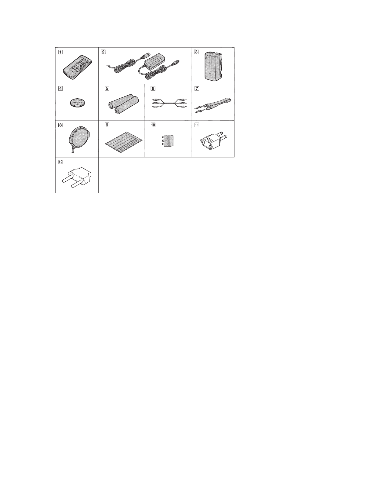
Supplied accessories
1 Wireless Remote Commander (1)
2 AC-L10A/L10B/L10C AC power
adaptor (1), Power cord (1)
3 NP-F330 Battery pack (1)
4 CR2025 Lithium Battery (1)
The lithium battery is already installed in your
camcorder.
5 Size AA (R6) battery for Remote
Commander (2)
6 A/V connecting cable (1)
!™ 2-pin conversion adaptor (1)
DCR-TRV110E: JE/TRV310E: JE/
TRV310: JE only
• Abbreviation
EE :
East European model
NE :
North European model
RU : Russian model
HK : Hong Kong model
BR : Brazilian model
JE : Tourist model
7 Shoulder strap (1)
8 Lens cap (1)
9 Label sheet for cassette (1)
Stick this label on the recorded cassette.
0 21-pin adaptor (1)
DCR-TR7000E/TR7100E/TRV210E: AEP , UK/
TRV310E: AEP, UK/TRV110E: AEP, UK,
EE, NE, RU only
!¡ 2-pin conversion adaptor (1)
DCR-TRV110E: E, HK/TRV110: E, HK, BR/
TRV110P/TR V310E: E, HK/TRV310: E, HK/
TRV310P only

— 4 —
Note : EE, NE, RU model is 360×.
Remark
NTSC : X251 is 28.6363MHz
PAL : X251 is 28.375MHz
960H:with IC503 of VC-213 board
®:with Q641-644 of VC-213 board
®:with REC button and Q641-
644 of VC-213 board
2.5 inch : with PD-105 board
3/3.5 inch : with PD-106 board
Color : with VF-126 board
B/W : with VF-129 board
CN
PAL
RMT-814
20×
360×
960H
®
®
3.0
89k
TYPE S
B/W
CD-213
CF-63
MA-355
PD-106
VF-129
SE-87
PJ-96
DCR-
TRV310/
TRV310P
US, E, HK,
JE, TW
NTSC
RMT -814
20×
360×
720H
®
®
3.5
105k
TYPE C
B/W
CD-212
CF-63
MA-355
PD-106
VF-129
SE-87
PJ-96
DCR-
TRV310E
AEP, UK
PAL
RMT-814
20×
80×
960H
®
✕
3.5
105k
TYPE S
B/W
CD-213
CF-63
MA-355
PD-106
VF-129
SE-87
PJ-96
E, HK, A US,
CN, JE
PAL
RMT-814
20×
360×
960H
®
®
3.5
105k
TYPE S
B/W
CD-213
CF-63
MA-355
PD-106
VF-129
SE-87
PJ-96
DCR-
TRV315
US, CND
NTSC
RMT-814
20×
360×
720H
®
®
3.0
89k
TYPE S
Color
CD-212
CF-63
MA-355
PD-106
VF-126
SE-87
PJ-96
DCR-
TR7000
US, CND
NTSC
RMT-814
20×
360×
720H
✕
®
✕
✕
✕
Color
CD-212
CF-65
MA-357✕VF-126
SE-89
PJ-98
DCR-
TR7000E/
TR7100E
AEP, UK
PAL
RMT-814
20×
80×
960H
✕
✕
✕
✕
✕
Color
CD-213
CF-65
MA-357✕VF-126
SE-89
PJ-98
Model
Destination
Color system
Remote Commander
Lens
Digital zoom
CCD imager
MONITOR IN
VTR REC
LCD (size)
LCD (pixel)
LCD type
View finder
CD board
CF board
MA board
PD board
VF board
SE board
PJ board
DCR-
TRV110/
TRV110P/
TRV103
US, CND,
E, HK, BR
NTSC
RMT-814
20×
360×
720H
®
®
2.5
61k
TYPE S
B/W
CD-212
CF-62
MA-354
PD-105
VF-129
SE-86
PJ-95
DCR-
TRV110E
AEP, UK,
EE, NE, RU
PAL
RMT -814
20×
80× (Note)
960H
®
✕
2.5
84k
TYPE S
B/W
CD-213
CF-62
MA-354
PD-105
VF-129
SE-86
PJ-95
E, HK, A US,
CN, JE
PAL
RMT-814
20×
360×
960H
®
®
2.5
61k
TYPE S
B/W
CD-213
CF-62
MA-354
PD-105
VF-129
SE-86
PJ-95
DCR-
TRV203
CND
NTSC
RMT-814
20×
360×
720H
®
®
3.0
89k
TYPE S
B/W
CD-212
CF-63
MA-355
PD-106
VF-129
SE-87
PJ-96
DCR-
TRV210
US, CND
NTSC
RMT-814
20×
360×
720H
®
®
3.0
89k
TYPE S
B/W
CD-212
CF-63
MA-355
PD-106
VF-129
SE-87
PJ-96
DCR-
TRV210E
AEP, UK
PAL
RMT-814
20×
80×
960H
®
✕
3.0
89k
TYPE S
B/W
CD-213
CF-63
MA-355
PD-106
VF-129
SE-87
PJ-96
Table for difference of function
• Abbreviation
CND : Canadian model
EE : East European model
NE : North European model
RU : Russian model
HK : Hong Kong model
AUS : Australian model
CN : Chinese model
BR : Brazilian model
JE : Tourist model
TW : Taiwan model

— 5 —
SERVICE NOTE
1. POWER SUPPLY DURING REPAIRS ····························· 8
2. TO TAKE OUT A CASSETTE WHEN NOT EJECT
(FORCE EJECT) ································································ 8
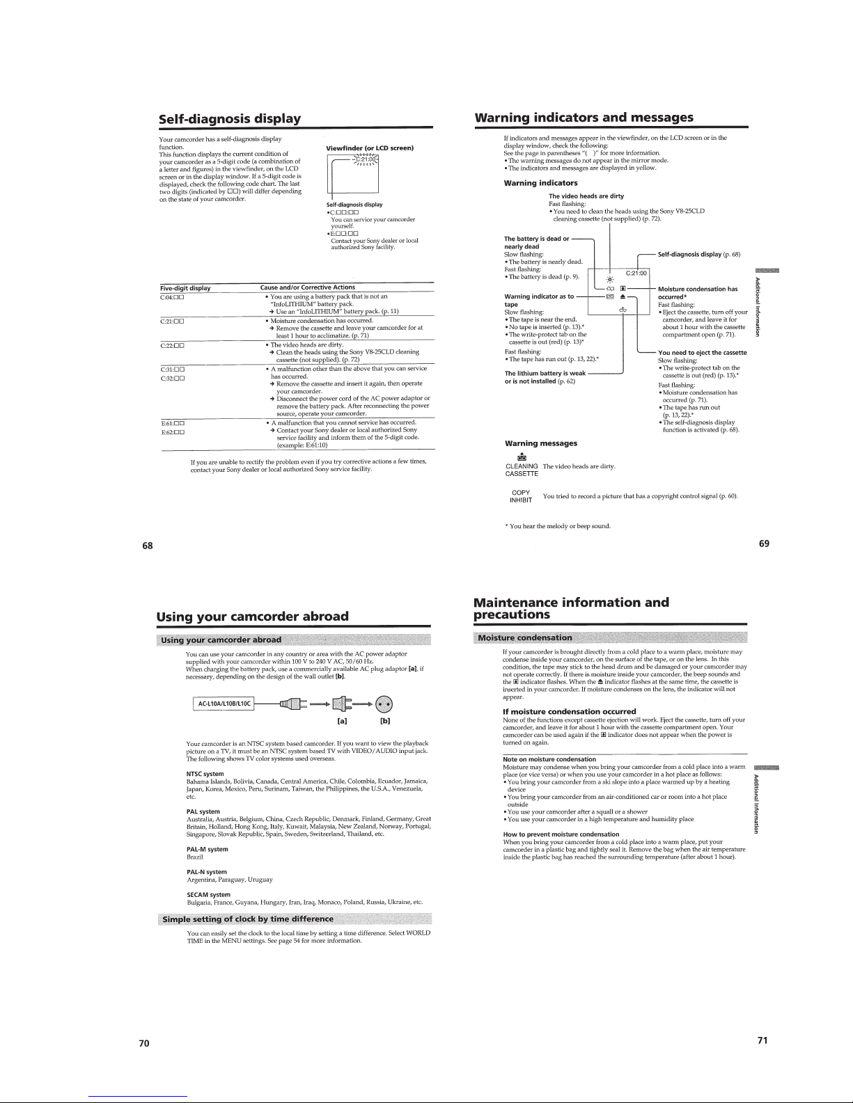
SELF-DIAGNOSIS FUNCTION
1. Self-diagnosis Function ······················································ 9
2. Self-diagnosis Display························································ 9
3. Service Mode Display ························································9
3-1. Display Method ··································································9
3-2. Switching of Backup No. ··················································· 9
3-3. End of Display···································································· 9
4. Self-dignosis Code Table·················································· 10
1. GENERAL
Quick Start Guide ······································································1-1
Getting Started···········································································1-1
Using this manual ··································································1-1
Checking supplied accessories ··············································1-1
Step 1: Preparing the power supply······································· 1-2
Step 2: Inserting a cassette ····················································1-3
Recording – Basics ····································································1-3
Recording a picture································································1-3
Checking the recording
– END SEARCH/EDITSEARCH/Rec Review·····················1-5
Playback – Basics ······································································1-5
Playing back a tape ································································1-5
Viewing the recording on TV ················································1-6
Advanced Recording Operations···············································1-6
Photo recording······································································1-6
Using the wide mode ·····························································1-7
Using the fader function ························································1-7
Using special effects – Picture effect·····································1-8
Using special effects – Digital effect·····································1-8
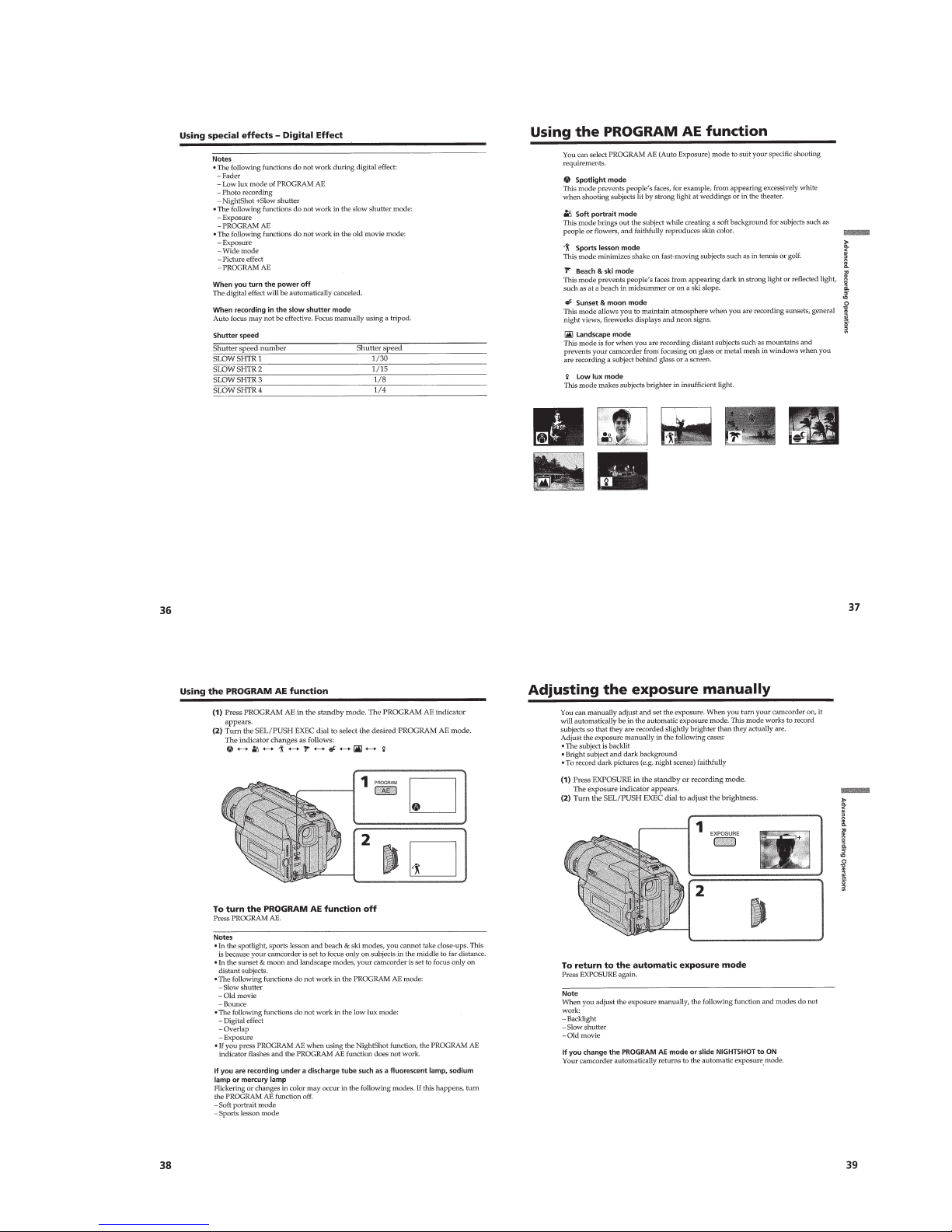
Using the PROGRAM AE function ·······································1-9
Adjusting the exposure manually ··········································1-9
Focusing manually······························································· 1-10
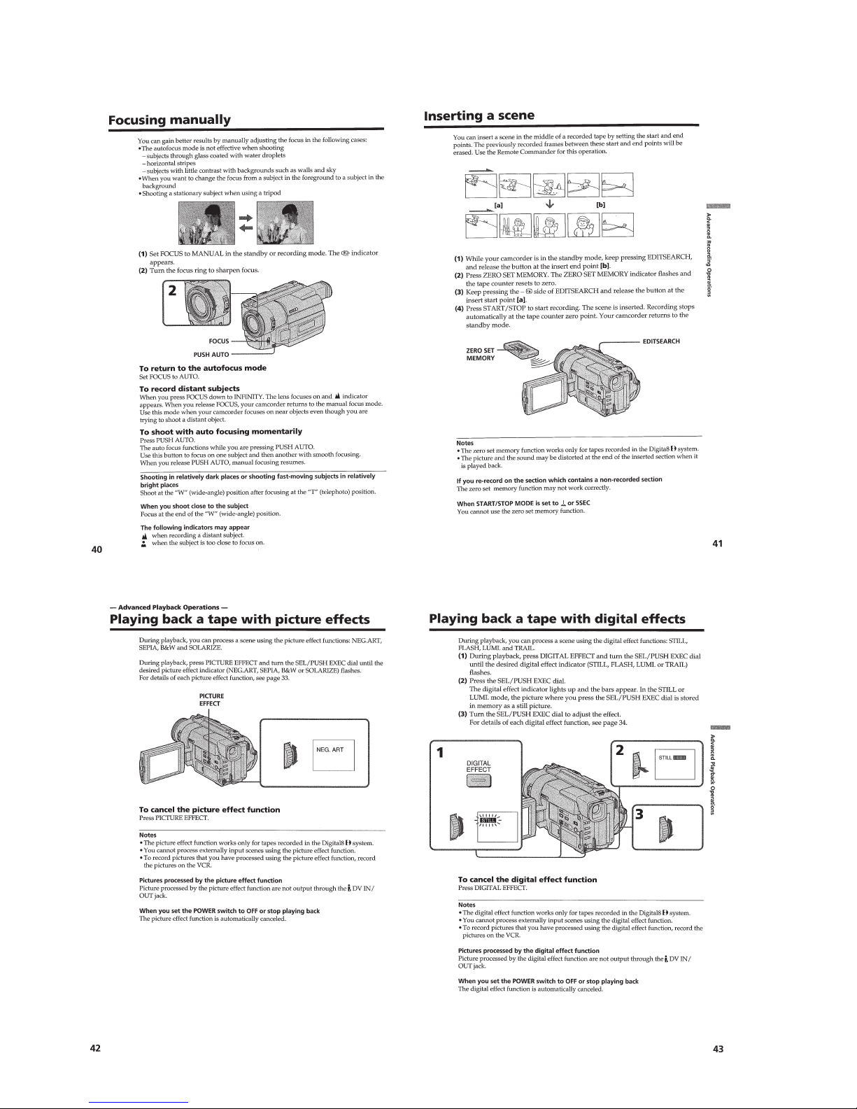
Inserting a scene ··································································1-10
Advanced Playback Operations···············································1-10
Playing back a tape with picture effects ······························1-10
Playing back a tape with digital effects ·······························1-10
Quickly locating a scene using the zero set memory
function ················································································1-11
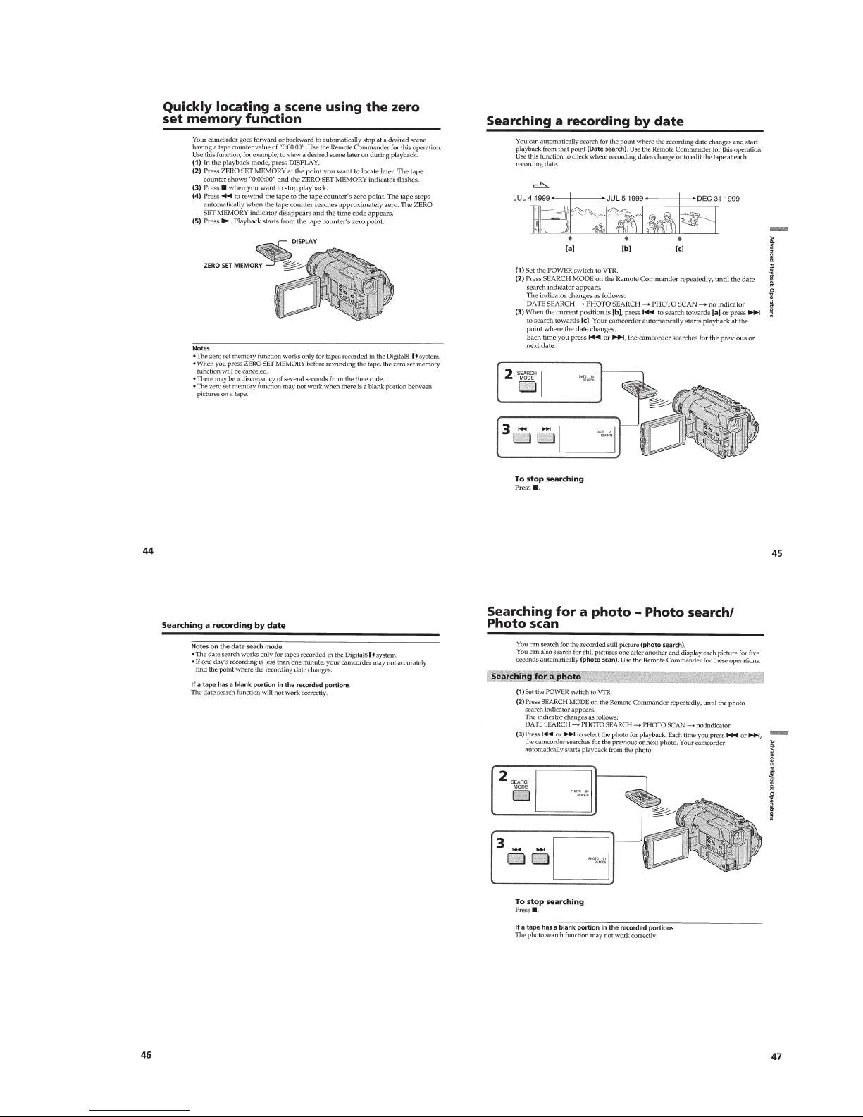
Searching a recording by date··············································1-11
Searching for a photo – Photo search/Photo scan················ 1-11
Editing on Other Equipment···················································· 1-12
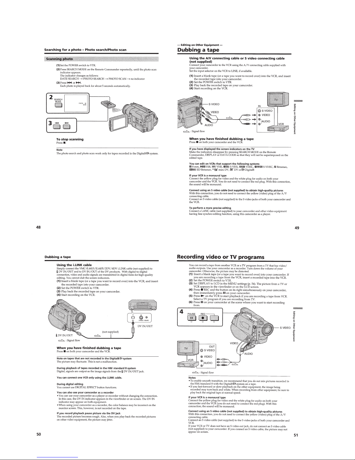
Dubbing a tape ·····································································1-12
Recording video or TV programs ········································1-12
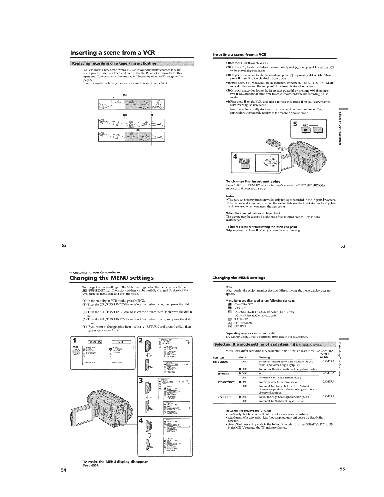
Inserting a scene from a VCR·············································· 1-13
Customizing Y our Camcorder ·················································1-13
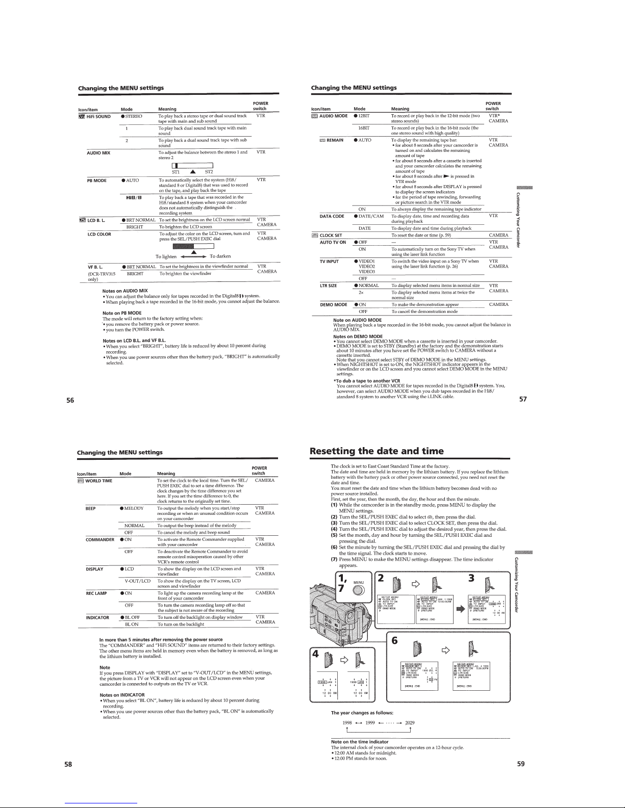
Changing the MENU settings ··············································1-13
Resetting the date and time··················································1-14
Additional Information ····························································1-14
Digital8 system, recording and playback·····························1-15
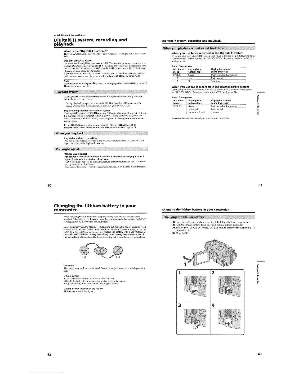
Changing the lithium battery in your camcorder ·················1-15
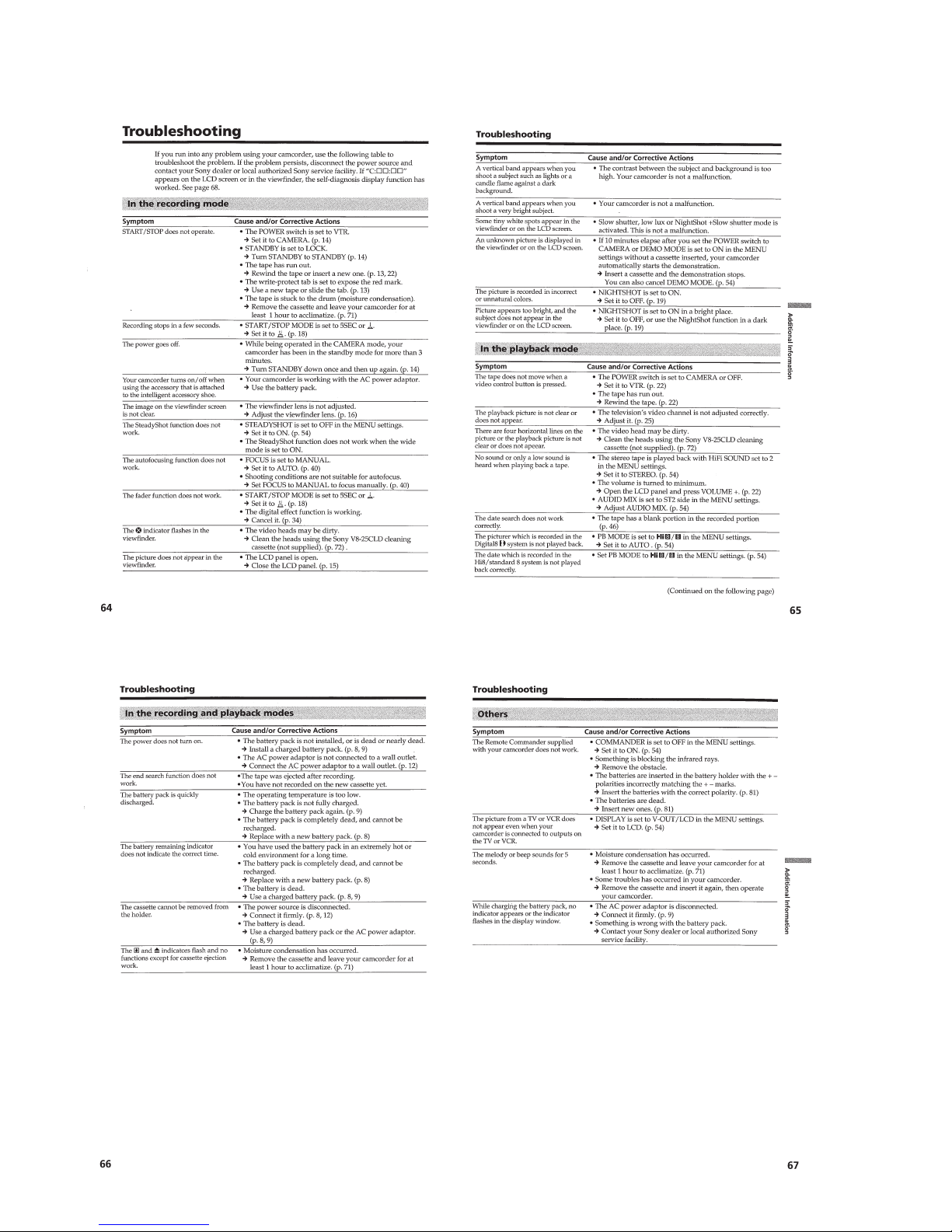
Troubleshooting ···································································1-16
Self-diagnosis display ··························································1-17
Warning indicators and messages ········································1-17
Using your camcorder abroad·············································· 1-17
Maintenance information and precautions···························1-17
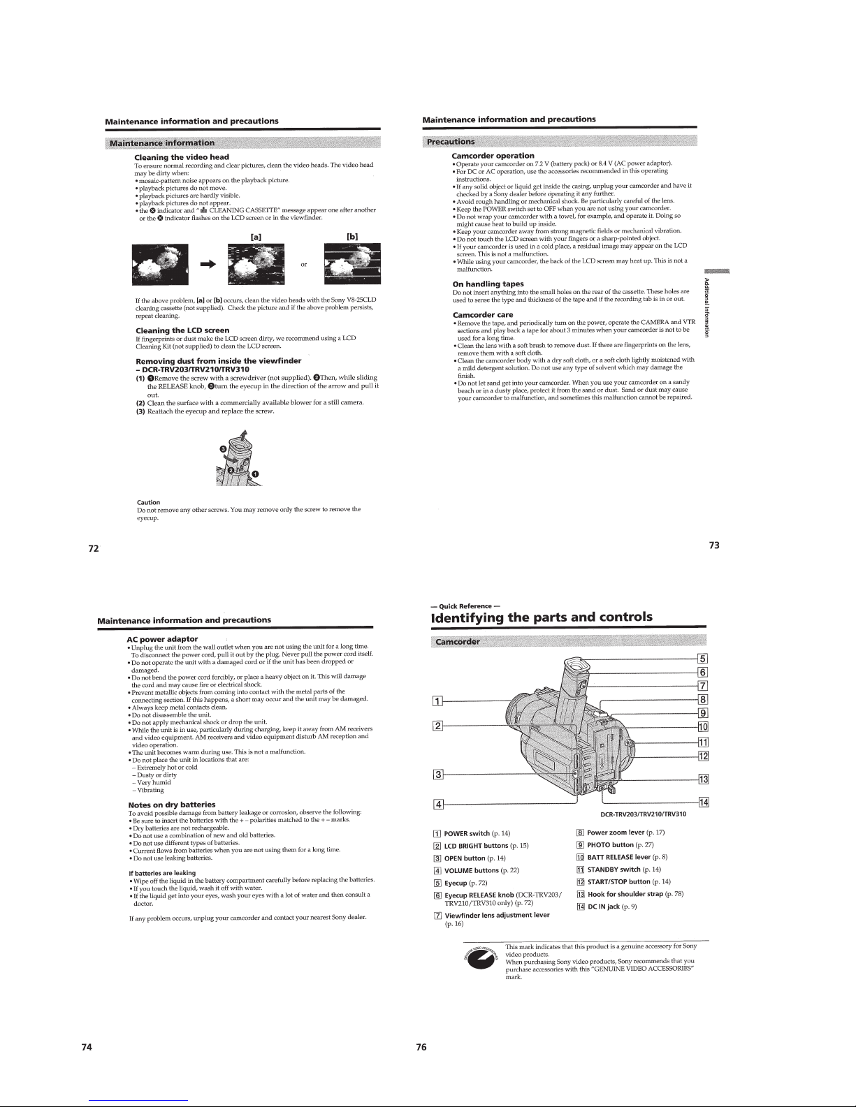
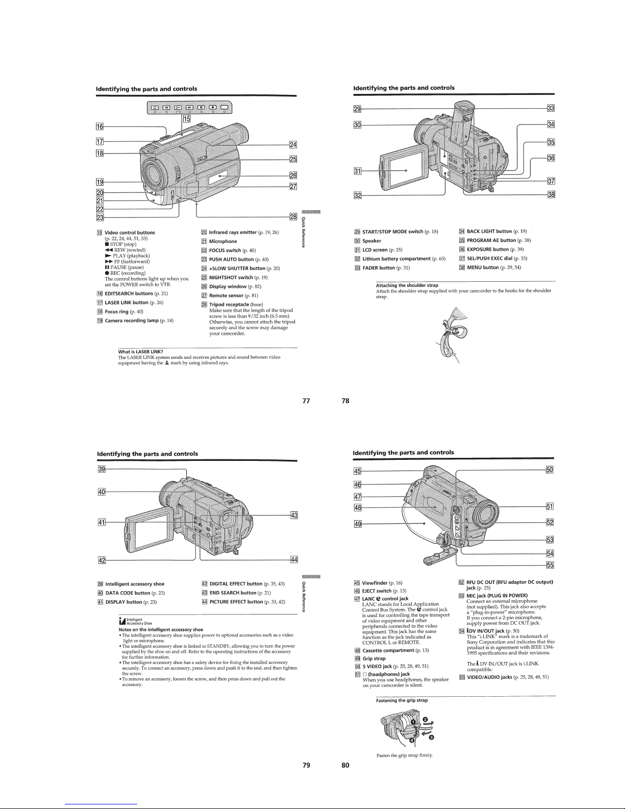
Quick Reference ······································································1-18
Identifying the parts and controls ········································1-18
Quick Function Guide ·························································1-20
2. DISASSEMBLY
2-1. 2.5 INCH LCD Unit, PD-105 Board ·······························2-2
2-2. 3.0/3.5 INCH LCD Unit, PD-106 Board·························2-3
2-3. F Panel Assembly, Cabinet (R) Assembly ·······················2-4
2-4. MA-354, 355, 357 Board ················································2-4
2-5. Mechanism Deck ·····························································2-5
2-6. EVF Block Assembly ······················································2-6
2-7. VF-129 Board (B/W EVF Model)···································2-7
2-8. VF-126 Board (Color EVF Model) ·································2-8
2-9. Lens Block·······································································2-9
2-10. Mechanism Deck, VC-213, DD-117,
PJ-95, 96, 98 Boards······················································2-10
2-11. CF-65 Board (TR Model) ··············································2-12
2-12. CF-62 Board (2.5 INCH LCD Model) ··························2-12
2-13. CF-63 Board (3.0/3.5 INCH LCD Model) ····················2-12
2-14. Circuit Boards Location ················································2-13
2-15. Flexible Boards Location ··············································2-14
3. BLOCK DIAGRAMS
3-1. Overall Block Diagram (1) ··············································3-1
Overall Block Diagram (2)··············································3-6
3-2. Power Block Diagram (1)················································3-9
Power Block Diagram (2)··············································3-13
4. PRINTED WIRING BOARDS AND
SCHEMATIC DIAGRAMS
4-1. Frame Schematic Diagram-1···········································4-1
Frame Schematic Diagram-2···········································4-5
4-2. Printed Wiring Boards and Schematic Diagrams ············4-9
• CD-212 (CCD Imager)
Printed Wiring Board and
Schematic Diagram ·······································4-10
• CD-213 (CCD Imager)
Printed Wiring Board and
Schematic Diagram ·······································4-13
• VC-213 (Camera Processor)(1/13)
Schematic Diagram .......................................4-15
• VC-213 (Y/C Processor)(2/13)
Schematic Diagram ·······································4-18
• VC-213 (Lens Motor Drive)(3/13)
Schematic Diagram ·······································4-21
• VC-213 (I/O SEL, IR, BBI)(4/13)
Schematic Diagram ·······································4-25
• VC-213 (VFD)(5/13)
Schematic Diagram ·······································4-29
• VC-213 (SFD, TFD, LIP)(6/13)
Schematic Diagram ·······································4-33
• VC-213 (TRX, TRF, TR W)(7/13)
Schematic Diagram ·······································4-35
• VC-213 (8mm PB RF AMP, D/A Converter)(8/13)
Schematic Diagram ·······································4-40
• VC-213 (8mm AFM Processor)(9/13)
Schematic Diagram ·······································4-43
• VC-213 (8mm Mechanism Control)(10/13)
Schematic Diagram ·······································4-49
• VC-213 (DV Mechanism Control)(11/13)
Schematic Diagram ·······································4-51
• FP-249 (S/T Reel Sensor), FP-356 (Top Sensor),
FP-355 (Tape LED) Flexible Board ····························4-55
• VC-213 (Servo)(12/13)
Schematic Diagram ·······································4-56
• VC-213 (HI Control)(13/13)
Schematic Diagram ·······································4-59
• VC-213 (Camera Processor, Y/C Processor, Lens Motor
Drive, IN/OUT Select, IR Transmitter, Base Band Input,
VFD, SFD, TFD, LIP, TRX, TRF, TRW, 8mm PB RF
AMP, D/A Converter, 8mm AFM Processor, 8mm
Mechanism Control, DV Mechanism Control, Servo,
HI Control)
Printed Wiring Board ····································4-65
TABLE OF CONTENTS

— 6 —
• SE-86/87/89 (Steady Shot), PJ-95/96/98 (AV IN/OUT)
Printed Wiring Boards···································4-70
• SE-86/87/89 (Steady Shot), PJ-95/96/98 (AV IN/OUT)
Schematic Diagrams ·····································4-73
• MA-354/355/357 (Stereo MIC AMP)
Printed Wiring Board ····································4-75
• MA-354/355/357 (Stereo MIC AMP)
Schematic Diagram ·······································4-77
• CF-62 (User Control)
Printed Wiring Board ....................................4-80
• CF-62 (User Control)
Schematic Diagram ·······································4-83
• CF-63 (User Control)
Printed Wiring Board ....................................4-87
• CF-63 (User Control)
Schematic Diagram ·······································4-91
• CF-65 (User Control)
Printed Wiring Board ....................................4-96
• CF-65 (User Control)
Schematic Diagram ·······································4-99
• PD-105 (RGB Decoder, LCD, Timing Generator,
Back Light Drive)
Printed Wiring Board
(2.5 INCH LCD Model)······························4-103
• PD-106 (RGB Decoder, LCD, Timing Generator,
Back Light Drive)
Printed Wiring Board
(3.0/3.5 INCH LCD Model)························4-105
• PD-105 (RGB Decoder, LCD)(1/2)
Schematic Diagram ·····································4-109
• PD-106 (RGB Decoder, LCD)(1/2)
Schematic Diagram ·····································4-111
• PD-105, 106 (RGB Decoder, LCD)(2/2)
Schematic Diagram ·····································4-114
• VF-129 (B/W EVF)
Printed Wiring Board (B/W EVF Model) ...4-117
• VF-129 (B/W EVF)
Schematic Diagram (B/W EVF Model)······ 4-118
• VF-126 (Color EVF)
Printed Wiring Board (Color EVF Model) ..4-121
• VF-126 (Color EVF)
Schematic Diagram (Color EVF Model) ····4-123
• DD-117 (DC/DC Converter)
Printed Wiring Board ··································4-129
• DD-117 (DC/DC Converter)
Schematic Diagram ·····································4-131
• FK-8500, SS-8500 (Control Switch Block)
Schematic Diagram ·····································4-138
5. ADJUSTMENTS
1. Before starting adjustment···············································5-1
1-1. Adjusting items when replacing main parts and boards··5-2
5-1. CAMERA SECTION ADJUSTMENT··························· 5-4
1-1. Preparations before Adjustment (Camera Section) ·········5-4
1-1-1.List of Service Tools ························································5-4
1-1-2.Preparations ····································································· 5-5
1-1-3.Precaution ········································································5-9
1. Setting the Switch···························································· 5-9
2. Order of Adjustments ······················································5-9
3. Subjects ···········································································5-9
1-2. Initialization of C, D, E, F Page Data····························5-10
1-2-1.Initialization of C Page Data ·········································5-10
1. Initializing the C Page Data···········································5-10
2. Modification of C Page Data·········································5-10
3. C Page Table ··································································5-10
1-2-2.Initialization of D Page Data ········································· 5-12
1. Initializing the D Page Data ··········································5-12
2. Modification of D Page Data·········································5-12
3. D Page Table··································································5-12
1-2-3.Initialization of E, F Page Data ·····································5-14
1. Initializing the E, F Page Data·······································5-14
2. Modification of E, F Page Data·····································5-14
3. F Page Table ··································································5-14
4. E Page Table ··································································5-18
1-3. Camera System Adjustments·········································5-21
1. HALL Adjustment ·························································5-21
2. Flange Back Adjustment (Using Minipattern Box)·······5-22
3. Flange Back Adjustment (Using Flange Back Adjustment
Chart Subject More Than 500m Away)·························5-23
3-1. Flange Back Adjustment (1)··········································5-23
3-2. Flange Back Adjustment (2)··········································5-23
4. Flange Back Check························································5-24
5. Picture Frame Setting ····················································5-24
6. AGC Gain Calibration Adjustment ·······························5-25
7. Color Reproduction Adjustment····································5-26
8. IRIS IN/OUT Adjustment ·············································5-27
9. Auto White Balance Standard Data Input ·····················5-28
10. Auto White Balance Adjustment ···································5-28
11. White Balance Check ····················································5-29
12. Angular Velocity Sensor Sensitivity Data Check ··········5-30
1-4. Color Electronic Viewfinder System Adjustments
(DCR-TR7000/TR7000E/TR7100E/TRV315)··············5-31
1. EVF Initial Data Input ···················································5-31
2. VCO Adjustment (VF-126 board)·································5-32
3. Bright Adjustment (VF-126 board) ·······························5-32
4. Contrast Adjustment (VF-126 board)····························5-33
5. Backlight Consumption Current Adjustment
(VF-126 board)······························································5-33
6. White Balance Adjustment (VF-126 board)··················5-34
1-5. Monochrome Electronic Viewfinder System Adjustments
(DCR-TRV103/TRV110/TRV110E/TRV110P/TRV203/
TRV210/TRV210E/TRV310/TRV310E/TRV310P)······5-35
1-5-1.Horizontal Slant Check ·················································5-35
1-5-2.Centering Adjustment ····················································5-35
1-5-3.Focus Adjustment ·························································· 5-35
1-5-4.Aberration Adjustment ··················································5-36
1-5-5.Horizontal Amplitude Adjustment (VF-129 board) ······5-36
1-5-6.Vertical Amplitude Adjustment (VF-129 board) ···········5-37
1-5-7.Brightness Adjustment (VF-129 Board)························5-37
1-5-8.Horizontal Amplitude, V ertical Amplitude,
Focus Check ··································································5-37
1-6. LCD System Adjustments
(DCR-TRV103/TRV110/TRV110E/TRV110P/TRV203/
TRV210/TRV210E/TRV310/TRV310E/TRV310P/
TRV315)········································································5-38
1. LCD Initial Data Input (1)·············································5-38
2. LCD Initial Data Input (2)·············································5-38
3. VCO Adjustment (PD-105/106 board)··························5-39
4. D range Adjustment (PD-105/106 board) ·····················5-39
5. Bright Adjustment (PD-105/106 board)························5-40
6. Contrast Adjustment (PD-105/106 board)·····················5-40
7. V-COM Level Adjustment (PD-105/106 board) ···········5-41
8. Color Adjustment (PD-105/106 board) ·························5-41
9. V-COM Adjustment (PD-105/106 board) ·····················5-42
10. White Balance Adjustment (PD-105/106 board)···········5-42
5-2. MECHANISM SECTION ADJUSTMENT··················5-43
2-1. Hi8/Standard 8mm Mode ·············································· 5-43
2-1-1.Operating Without Cassette ···········································5-43
2-1-2.Tape Path Adjustment···················································· 5-43
1. Preparations for Adjustment·········································· 5-43
2-2. Digital8 Mode································································5-44
2-2-1.How to Enter Record Mode Without Cassette ··············5-44
2-2-2.How to Enter Playback Mode Without Cassette ··········· 5-44
2-2-3.Overall Tape Path Check ···············································5-44

— 7 —
* The color reproduction frame is shown on page 323.
1. Recording of the tape path check signal························ 5-44
2. Tape path check ·····························································5-44
5-3. VIDEO SECTION ADJUSTMENT······························5-45
3-1. Preparations Before Adjustments ··································5-45
3-1-1.Equipment to Required··················································5-45
3-1-2.Precautions on Adjusting···············································5-46
3-1-3.Adjusting Connectors ····················································5-47
3-1-4.Connecting the Equipment ············································5-47
3-1-5.Alignment Tape ····························································· 5-48
3-1-6.Input/Output Level and Impedance ·······························5-49
3-2. System Control System Adjustment······························5-50
1. Initialization of C, D, E, F Page Data···························· 5-50
2. Battery End Adjustment (VC-213 board)······················5-50
3-3. Servo and RF System Adjustments ·······························5-51
1. PLL f0 & LPF f0 Pre-adjustment (VC-213 board) ········· 5-51
2. Switching Position Adjustment (VC-213 board)··········· 5-51
3. AGC Center Level Adjustment (VC-213 board) ···········5-52
4. APC & AEQ Adjustment (VC-213 board) ···················· 5-52
5. PLL f0 & LPF f0 Final Adjustment (VC-213 board)······ 5-53
6. Hi8/standard 8mm Switching Position Adjustment
(VC-214 board) ·····························································5-53
7. CAP FG Offset Adjustment (VC-213 board)················5-54
3-4. Video System Adjustments ············································5-55
3-4-1.Video System Adjustments············································5-55
1. 27 MHz/36 MHz Origin Oscillation Adjustment
(VC-213 board) ·····························································5-55
2. Chroma BPF f0 Adjustment (VC-213 board) ················5-55
3. S VIDEO OUT Y Level Adjustment (VC-213 board)···5-56
4. S VIDEO OUT Chroma Level Adjustment
(VC-213 board) ·····························································5-56
5. VIDEO OUT Y, Chroma Level Adjustment
(VC-213 board) ·····························································5-57
6. Hi8/standard 8mm 14 MHz Origin Oscillation
Adjustment (VC-213 board)········································· 5-57
7. BBI PLL Adjustment (VC-213 board) ··························5-58
8. Hi8/standard 8mm Y OUT Level Adjustment
(VC-213 board) ·····························································5-58
9. Hi8/standard 8mm Chroma Level Adjustment
(VC-213 board) ·····························································5-59
10. Hi8/standard 8mm AFC f
0
Adjustment
(VC-213 board) ·····························································5-59
11. Hi8/standard 8mm RP Filter f0 Adjustment
(VC-213 board) ·····························································5-60
3-4-2.BIST Check ···································································5-61
1. Playback System Check ················································5-61
1-1. Preparation for Playback ···············································5-61
1-2. IC104 (TRX) BIST (PB) Check ····································5-61
1-3. IC302 (TFD) BIST (PB) Check ····································5-61
1-4. IC301 (SFD) BIST (PB) Check·····································5-61
1-5. IC351 (VFD) BIST (PB) Check ····································5-62
2. Recording System Check ··············································5-64
2-1. Preparations for Recording············································ 5-64
2-2. IC351 (VFD) BIST (REC) Check ·································5-64
2-3. IC301 (SFD) BIST (REC) Check·································· 5-64
2-4. IC302 (TFD) BIST (REC) Check ·································5-64
2-5. IC104 (TRX) BIST (REC) Check ·································5-65
3-5. IR Transmitter Adjustments···········································5-66
1. IR Video Carrier Frequency Adjustment
(VC-213 board) ·····························································5-66
2. IR Video Deviation Adjustment (VC-213 board) ·········· 5-66
3. IR Audio Deviation Adjustment (VC-213 board) ·········5-67
3-6. Audio System Adjustment·············································5-68
1. Hi8/standard 8mm AFM BPF f0 Adjustment
(VC-213 board) ·····························································5-68
2. Hi8/standard 8mm AFM 1.5 MHz Deviation Adjustment
(VC-213 board) ·····························································5-69
3. Hi8/standard 8mm AFM 1.7 MHz Deviation Adjustment
(VC-213 board) ·····························································5-69
4. Digital8 Playback Level Check ·····································5-69
5. Overall Level Characteristics Check ·····························5-69
6. Overall Distortion Check···············································5-69
7. Overall Noise level Check············································· 5-70
8. Overall Separation Check·············································· 5-70
5-4. SER VICE MODE··························································5-71
4-1. Adjustment Remote Commander ··································5-71
1. Using the Adjustment Remote Commander·················· 5-71
2. Precautions Upon Using the Adjustment Remote
Commander ···································································5-71
4-2. Data Process ··································································5-72
4-3. Service Mode································································· 5-73
1. Setting the Test Mode ···················································· 5-73
2. Emergence Memory Address ········································5-73
2-1. C Page, Emergence Memory Address ···························5-73
2-2. F Page, Emergence Memory Address ···························5-74
2-3. EMG Code (Emergency Code) ·····································5-74
2-4. MSW Code ····································································5-75
3. Bit V alue Discrimination ···············································5-76
4. Input/Output Check ·······················································5-76
5. LED, LCD (Display Window) Check ···························5-76
6. Record of Use Check····················································· 5-77
7. Switch Check (1) ··························································· 5-77
8. Switch Check (2) ··························································· 5-78
9. Audio (L) Jack Check····················································5-78
10. Headphone Jack Check ·················································5-78
6. REPAIR PARTS LIST
6-1. Exploded Views·······························································6-1
6-1-1.Front Panel (N) and Battery Panel (P) Block Assembly ·6-1
6-1-2.Cabinet (R) Block Assembly (TR Model)·······················6-2
6-1-3.Cabinet (R) Block Assembly (2.5 INCH LCD Model) ···6-3
6-1-4.Cabinet (R) Block Assembly
(3.0/3.5 INCH LCD Model) ············································6-4
6-1-5.Cabinet (L) Block and Main Boards Assembly···············6-5
6-1-6.LCD Block Assembly (2.5 INCH LCD Model) ··············6-6
6-1-7.LCD Block Assembly (3.0/3.5 INCH LCD Model) ········6-7
6-1-8.B/W EVF Block Assembly··············································6-8
6-1-9.Color EVF Block Assembly ············································6-9
6-1-10. Lens Block Assembly ················································· 6-10
6-1-11. Cassette Compartment Assembly ·······························6-11
6-1-12. LS Chassis Assembly··················································6-12
6-1-13. Mechanism Chassis Assembly····································6-13
6-2. Electrical Parts List ·······················································6-14
— 8 —
SERVICE NOTE
1. POWER SUPPLY DURING REPAIRS
In this unit, about 10 seconds after power is supplied (8.4V) to the
battery terminal using the service power cord (J-6082-223-A), the
power is shut off so that the unit cannot operate.
This following two methods are av ailable to pre vent this. Take note
of which to use during repairs.
Method 1.
Connect the servicing remote commander RM-95 (J-6082-053-B)
to the LANC jack, and set the remote commander switch to the
“ADJ” side.
Method 2.
Press the battery switch of the battery terminal using adhesive tape,
etc.
Method 3.
Use the DC IN terminal. (Use the AC power adaptor.)
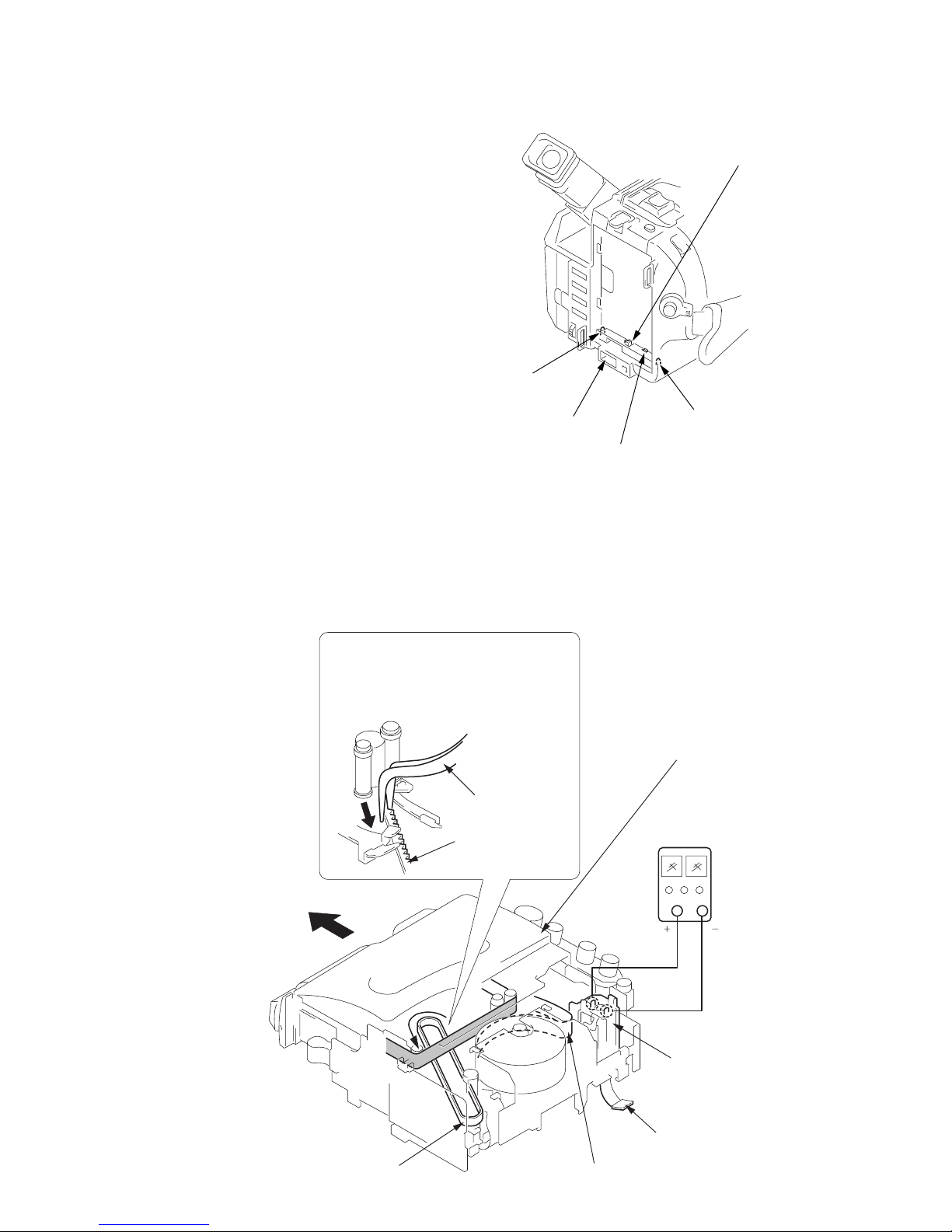
6
Pull the timing belt in the direction of
arrow
A
with a pincette while pressing
the cassette lid (take care not to damage)
to adjust the bending of a tape.
7
Let go your hold the cassette
lid and rise the cassette
compartment to take out a cassette.
Pincette
Timing belt
Timing belt
Press the cassette lid to rise
the cassette compartment
[DC power supply]
(+5V)
Adjust the bending of a tape
Disconnect CN901
of VC-213 board.
Loading motor
DC IN terminal
Battery switch
Battery terminal
’
Battery terminal
‘
Battery SIG terminal
2. TO TAKE OUT A CASSETTE WHEN NOT EJECT (FORCE EJECT)
1 Refer to 2-1. to remove the front panel assembly.
2 Refer to 2-1. to remove the cabinet (R) assembly.
3 Refer to 2-1. to remove the battery panel assembly.
4 Refer to 2-1. to remove the cabinet (L) assembly.
5 Disconnect CN901 of VC-213 board.
6 Add +5V from the DC POWER SUPPLY and unload with a
pressing the cassette lid.
— 9 —
SELF-DIAGNOSIS FUNCTION
1. Self-diagnosis Function
When problems occur while the unit is operating, the self-diagnosis
function starts working, and displays on the viewfinder or Display
window what to do. This function consists of two display; selfdiagnosis display and service mode display.
Details of the self-diagnosis functions are provided in the Instruction
manual.
Note: The “self-diagnosis display” data will be back ed up by the coin-type lithium battery (CF-62/63/65 board BH001). When
this coin-type lithium battery is disconnected, the “self-diagnosis display” data will be lost by initialization.
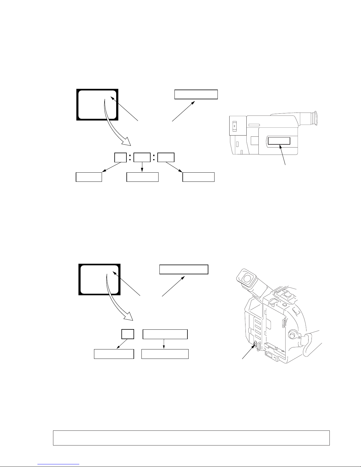
2. Self-diagnosis Display
When problems occur while the unit is operating, the counter of the
viewfinder or Display window shows a 4-digit display consisting
of an alphabet and numbers, which blinks at 3.2 Hz. This 5-character
display indicates the “repaired by:”, “block” in which the problem
occurred, and “detailed code” of the problem.
3. Service Mode Display
The service mode display shows up to six self-diagnosis codes shown in the past.
3-1. Display Method
While pressing the “STOP” key, set the switch fr om OFF to “VTR or PLAYER”, and contin ue pressing the “STOP” key for 5 seconds
continuously. The service mode will be displayed, and the counter will show the backup No. and the 5-character self-diagnosis codes.
3-2. Switching of Backup No.
By rotating the control dial, past self-diagnosis codes will be shown in order. The backup No. in the [] indicates the order in which the
problem occurred. (If the number of problems which occurred is less than 6, only the number of problems which occurred will be shown.)
[1] : Occurred first time [4] : Occurred fourth time
[2] : Occurred second time [5] : Occurred fifth time
[3] : Occurred third time [6] : Occurred the last time
3-3. End of Display
Turning OFF the power supply will end the service mode display.
Order of previous errors
Backup No.
Self-diagnosis Codes
C : 3 1 : 1 1
[3]
Lights up
Viewfinder
[3] C : 3 1 : 1 1
3 C : 3 1 : 11
Display window
1 1
3 1
C : 3 1 : 11
C
Repaired by:
Refer to page 10 and 11.
Self-diagnosis Code Table.
Indicates the appropriate
step to be taken.
E.g.
31 ....Reload the tape.
32 ....Turn on power again.
Block
Detailed Code
Blinks at 3.2Hz
C : Corrected by customer
H : Corrected by dealer
E : Corrected by service
engineer
Viewfinder Display window
C : 3 1 : 1 1
Display window
Control dial

— 10 —
4. Self-diagnosis Code Table
C
C
C
C
C
C
C
C
C
C
C
C
C
C
C
C
C
C
C
C
C
C
C
C
C
C
C
C
C
Block
Function
21
22
23
31
31
31
31
31
31
31
31
31
31
31
31
31
32
32
32
32
32
32
32
32
32
32
32
32
32
Detailed
Code
00
00
00
10
11
20
21
22
23
30
31
40
41
42
43
44
10
11
20
21
22
23
30
31
40
41
42
43
44
Symptom/State
Condensation.
Video head is dirty.
Non-standard battery is used.
LOAD direction. Loading does not
complete within specified time
UNLOAD direction. Loading does not
complete within specified time
T reel side tape slacking when unloading
.
S reel
side tape slacking when unloading
.
T reel fault.
S reel fault.
FG fault when starting capstan.
FG fault during normal capstan operations.
FG fault when starting drum.
PG fault when starting drum.
FG fault during normal drum operations.
PG fault during normal drum operations.
Phase fault during normal drum operations.
LOAD direction loading motor time-
out.
UNLOAD direction loading motor
time-out.
T reel side tape slacking when
unloading.
S reel side tape slacking when
unloading.
T reel fault.
S reel fault.
FG fault when starting capstan.
FG fault during normal capstan
operations.
FG fault when starting drum.
PG fault when starting drum.
FG fault during normal drum
operations.
PG fault during normal drum
operations.
Phase fault during normal drum
operations.
Self-diagnosis Code
Repaired by:
Correction
Remove the cassette, and insert it again after one hour.
Clean with the optional cleaning cassette.
Use the InfoLITHIUM battery.
Load the tape again, and perform operations from the beginning.
Load the tape again, and perform operations from the beginning.
Load the tape again, and perform operations from the beginning.
Load the tape again, and perform operations from the beginning.
Load the tape again, and perform operations from the beginning.
Load the tape again, and perform operations from the beginning.
Load the tape again, and perform operations from the beginning.
Load the tape again, and perform operations from the beginning.
Load the tape again, and perform operations from the beginning.
Load the tape again, and perform operations from the beginning.
Load the tape again, and perform operations from the beginning.
Load the tape again, and perform operations from the beginning.
Load the tape again, and perform operations from the beginning.
Remove the battery or power cable, connect, and perform
operations from the beginning.
Remove the battery or power cable, connect, and perform
operations from the beginning.
Remove the battery or power cable, connect, and perform
operations from the beginning.
Remove the battery or power cable, connect, and perform
operations from the beginning.
Remove the battery or power cable, connect, and perform
operations from the beginning.
Remove the battery or power cable, connect, and perform
operations from the beginning.
Remove the battery or power cable, connect, and perform
operations from the beginning.
Remove the battery or power cable, connect, and perform
operations from the beginning.
Remove the battery or power cable, connect, and perform
operations from the beginning.
Remove the battery or power cable, connect, and perform
operations from the beginning.
Remove the battery or power cable, connect, and perform
operations from the beginning.
Remove the battery or power cable, connect, and perform
operations from the beginning.
Remove the battery or power cable, connect, and perform
operations from the beginning.

— 11 —
E
E
E
E
Block
Function
61
61
62
62
Detailed
Code
00
10
00
01
Symptom/State
Difficult to adjust focus
(Cannot initialize focus.)
Zoom operations fault
(Cannot initialize zoom lens.)
Handshake correction function does not
work well. (With pitch angular velocity
sensor output stopped.)
Handshake correction function does not
work well. (With yaw angular velocity
sensor output stopped.)
Self-diagnosis Code
Repaired by:
Correction
Inspect the lens block focus reset sensor (Pin !™ of CN551 of VC213 board) when focusing is performed when the control dial is
rotated in the focus manual mode and the focus motor drive circuit
(IC551 of VC-213 board) when the focusing is not performed.
Note: Use the remote commander RM-95 only for the model without the
focus dial.
Inspect the lens block zoom reset sensor (Pin !¢ of CN551 of VC213 board) when zooming is performed when the zoom lens is
operated and the zoom motor drive circuit (IC551 of VC-213 board)
when zooming is not performed.
Inspect pitch angular velocity sensor (SE651 of SE-86/87/89
board) peripheral circuits.
Inspect yaw angular velocity sensor (SE652 of SE-86/87/89
board) peripheral circuits.

1-1
SECTION 1
GENERAL
This section is extracted from instruction
manual. (3-865-973-11)
DCR-TRV103/TRV110/TRV110E/TRV110P/TRV203/TRV210/
TRV210E/TRV310/TRV310E/TRV310P/TRV315
DCR-TR7000/TR7000E/TR7100E

1-2
1-3
1-4

1-5

1-6
1-7
1-8
1-9
1-10
1-11
1-12
1-13
1-14
1-15
1-16
1-17
1-18
1-19
 Loading...