

Sony DCR-PC110E Service Manual
DCR-PC110E
RMT-811
SERVICE MANUAL
SERVICE MANUALSERVICE MANUAL
Level 1
Ver 1.0 2000. 09
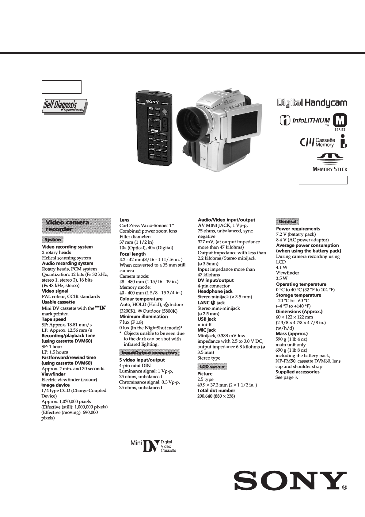
SPECIFICATIONS
AEP Model
UK Model
J MECHANISM
— Continued on next page —
DIGITAL VIDEO CAMERA RECORDER
SAFETY-RELATED COMPONENT WARNING!!
COMPONENTS IDENTIFIED BY MARK 0 OR DOTTED LINE WITH
MARK 0 ON THE SCHEMATIC DIAGRAMS AND IN THE PARTS
LIST ARE CRITICAL TO SAFE OPERATION. REPLACE THESE
COMPONENTS WITH SONY PARTS WHOSE PART NUMBERS
APPEAR AS SHOWN IN THIS MANUAL OR IN SUPPLEMENTS
PUBLISHED BY SONY.
SAFETY CHECK-OUT
After correcting the original service problem, perform the following
safety checks before releasing the set to the customer.
1. Check the area of your repair for unsoldered or poorly-soldered
connections. Check the entire board surface for solder splashes
and bridges.
2. Check the interboard wiring to ensure that no wires are
"pinched" or contact high-wattage resistors.
3. Look for unauthorized replacement parts, particularly
transistors, that were installed during a previous repair . Point
them out to the customer and recommend their replacement.
4. Look for parts which, through functioning, show obvious signs
of deterioration. Point them out to the customer and
recommend their replacement.
5. Check the B+ voltage to see it is at the values specified.
6. Flexible Circuit Board Repairing
• Keep the temperature of the soldering iron around 270˚C
during repairing.
• Do not touch the soldering iron on the same conductor of the
circuit board (within 3 times).
• Be careful not to apply force on the conductor when soldering
or unsoldering.
— 2 —
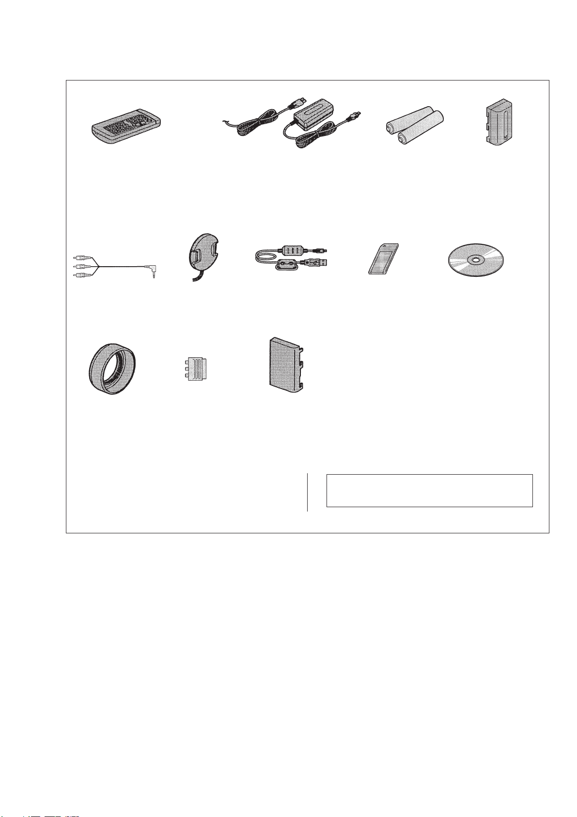
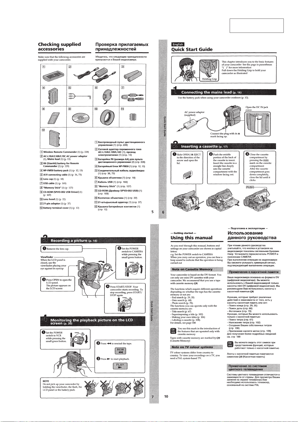
Checking supplied accessories.
Check that the following accessories are supplied with your camcorder.
Wireless Remote Commander (1)
RMT-811
1-475-950-21
A/V connecting cable
(1.5m) (1)
1-765-080-11
Lens hood (1)
3-063-797-01
Lens cap (1)
X-3949-944-1
21-pin adaptor (1)
1-573-291-11
AC-L10A/L10B/L10C
AC power adaptor (1)
0
1-475-599-11
Power cord (1) (AEP only)
0
1-575-131-11
Power cord (with filter) (1) (UK only)
0
1-783-374-11
USB cable (1)
1-757-293-11
Battery terminal cover (1)
3-057-482-01
Size AA (R6) battery for
Remote Commander (2)
(not supplied)
Memory Stick (1)
A-7033-740-A
NP-FM50
battery pack (1)
(not supplied)
CD-ROM
(SPVD-002 USB Driver)
3-063-797-01
Other accessories
3-063-381-11 MANUAL, INSTRUCTION (ENGLISH/RUSSIAN)(AEP,UK)
3-063-381-21 MANUAL, INSTRUCTION (SPANISH/PORTUGUESE)(AEP)
3-063-381-31 MANUAL, INSTRUCTION (GERMAN/FRENCH)(AEP)
3-063-381-41 MANUAL, INSTRUCTION (ITALIAN/DUTCH)(AEP)
Note : The components identified by mark 0 or dotted
line with mark 0 are critical for safety.
Replace only with part number specified.
— 3 —

TABLE OF CONTENTS
SERVICE NOTE
1. POWER SUPPLY DURING REPAIRS ····························· 5
2. HOW TO OPEN THE FLASH WHEN THE FLASH
DOESN’T OPEN ······························································· 5
3. TO TAKE OUT A CASSETTE WHEN NOT EJECT
(FORCE EJECT) ································································5
4. DISCHARGING OF THE FLASHLIGHT POWER
SUPPLY CAPACITOR ······················································ 6
4-1. PREPARING THE SHORT JIG········································· 6
4-2. DISCHARGING THE CAPACITOR································· 6
SELF-DIAGNOSIS FUNCTION
1. SELF-DIAGNOSIS FUNCTION······································· 7
2. SELF-DIAGNOSIS DISPLAY ·········································· 7
3. SERVICE MODE DISPLAY ············································· 7
3-1. Display Method ·································································· 7
3-2. Switching of Backup No. ··················································· 7
3-3. End of Display···································································· 7
4. SELF-DIAGNOSIS CODE TABLE··································· 8
1. MAIN PARTS
1. ORNAMENTAL PARTS···················································· 9
2. DISASSEMBLY······························································· 10
2-1. PD-134 BOARD, INVERTER TRANSFORMER UNIT ·· 11
2-2. CABINET (L) BLOCK ASSEMBLY ······························ 11
2-3. EVF BLOCK ASSEMBLY ·············································· 12
2-4. VTR OVERALL SECTION,
CABINET (R) BLOCK ASSEMBLY ······························ 12
2-5. FLASH UNIT (MC), ST CABINET (LOWER) ·············· 13
2-6. FJ-027 BOARD································································ 13
2-7. CD-285 BOARD, LENS SECTION ································ 14
2-8. AI-021, VC-253 BOARDS, MECHANISM DECK ········ 14
2-9. CONTROL SWITCH BLOCK (PS30550),
CONTROL SWITCH BLOCK (FK30550)······················ 15
2-10. LCD HINGE ASSEMBLY ··············································· 16
3. REPAIR PARTS LIST ······················································ 17
3-1. EXPLODED VIEWS ······················································· 17
3-1-1.OVERALL SECTION······················································ 17
3-1-2.CABINET (L) SECTION················································· 18
3-1-3.EVF SECTION································································· 19
3-1-4.VTR OVERALL SECTION············································· 20
3-1-5.CABINET (R) SECTION-1 ············································· 21
3-1-6.CABINET (R) SECTION-2 ············································· 22
2. GENERAL
Checking supplied accessories ··················································· 23
Quick Start Guide ······································································· 23
Getting started
Using this manual ··································································· 23
Step 1 Preparing the power supply ········································· 24
Installing the battery pack····················································· 24
Charging the battery pack ····················································· 24
Connecting to the mains ······················································· 25
Step 2 Inserting a cassette······················································· 25
Recording –Basics
Recording a picture································································· 25
Shooting backlit subjects –BACK LIGHT ··························· 27
Shooting in the dark –NightShot/Super NightShot ·············· 27
Self-timer recording······························································ 28
END SEARCH ····································································· 28
Playback –Basics
Playing back a tape ································································· 28
Viewing the recording on TV ················································· 30
Advanced Recording Operations
Recording a still image on a tape –Tape Photo recording ······ 31
Adjusting the white balance manually···································· 32
Using the wide mode ······························································ 33
Using the fader function ························································· 33
Using special effects –Picture effect······································· 34
Using special effects –Digital effect······································· 34
Using the PROGRAM AE function ········································ 35
Adjusting the exposure manually ··········································· 35
Focusing manually·································································· 36
Advanced Playback Operations
Playing back a tape with picture effects ································· 36
Playing back a tape with digital effects ·································· 36
Enlarging images recorded on –Tape PB ZOOM ·················· 37
Quickly locating a scene using the zero set memory function·····
Searching the boundaries of recorded tape by title
–Title search········································································· 38
Searching a recording by date –Date search··························· 38
Searching for a photo –Photo search/Photo scan···················· 38
Editing
Dubbing a tape ········································································ 39
Dubbing only desired scenes –Digital program editing ········· 40
Using with analog video unit and personal computer
–Signal convert function······················································ 43
Recording video or TV programmes ······································ 44
Inserting a scene from a VCR –Insert editing························· 45
Audio dubbing ········································································ 45
Superimposing a title ······························································ 46
Making your own titles ··························································· 47
Labeling a cassette ·································································· 48
Customizing Y our Camcorder
Changing the menu settings···················································· 48
Resetting the date and time····················································· 50
“Memory Stick” Operations
Using a “Memory Stick” –introduction ·································· 51
Recording still images on “Memory Stick”s
–Memory photo recording ··················································· 54
Recording an image from a mini DV tape as a still image ····· 56
Recoding moving pictures on “Memory Stick”s
–MPEG movie recoding ······················································ 57
Recoding a picture from a mini DV tape as a moving picture ·· 57
Superimposing a still image in a “Memory Stick” on a
moving picture –MEMORY MIX ·········································· 58
Copying still images from a mini DV tape –Photo save ········· 59
Viewing a still image –Memory photo playback ···················· 59
Viewing a moving picture –MPEG movie playback ·············· 60
Viewing images using a personal computer ··························· 61
Copying the images recorded on “Memory Stick”s to mini
DV tapes ················································································· 63
Enlarging still images recorded on “Memory Stick”s
–Memory PB ZOOM ··························································· 63
Playing back images in a continuous loop – SLIDE SHOW·· 64
Preventing accidental erasure –Image protection ··················· 64
Deleting images ······································································ 65
Writing a print mark –PRINT MARK···································· 66
Additional Information
Usable cassettes ······································································ 66
About i.LINK·········································································· 67
Troubleshooting ······································································ 67
Self-diagnosis display ····························································· 69
Warning indicators and messages ··········································· 69
Using your camcorder abroad················································· 70
Maintenance information and precautions······························ 70
Quick Reference
Identifying the parts and controls ··········································· 71
Quick Function Guide ···························································· 74
37
— 4 —
SERVICE NOTE
1. POWER SUPPLY DURING REPAIRS
In this unit, about 10 seconds after power is supplied to the battery terminal using the regulated power supply (8.4V), the po wer is shut of f so
that the unit cannot operate.
This following two methods are available to prevent this. Take note of which to use during repairs.
Method 1.
Use the AC power adaptor (AC-L10, AC-VQ800 etc.).
Method 2.
Connect the servicing remote commander RM-95 (J-6082-053-B) to the LANC jack, and set the commander switch to the “ADJ” side.
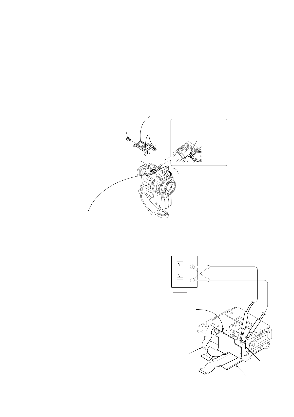
2. HOW TO OPEN THE FLASH WHEN THE FLASH DOESN’T OPEN
3
Cabinet (upper)
1
Screw
(M1.7
lock ace, p2
×
4),
2
Two claws
5
Push the lock plate in the
direction of the arrow
to open the flash unit.
Lock plate
B
B
4
Move the microphone block
in the direction of the arrow
A
A
.
6
Open the flash unit.
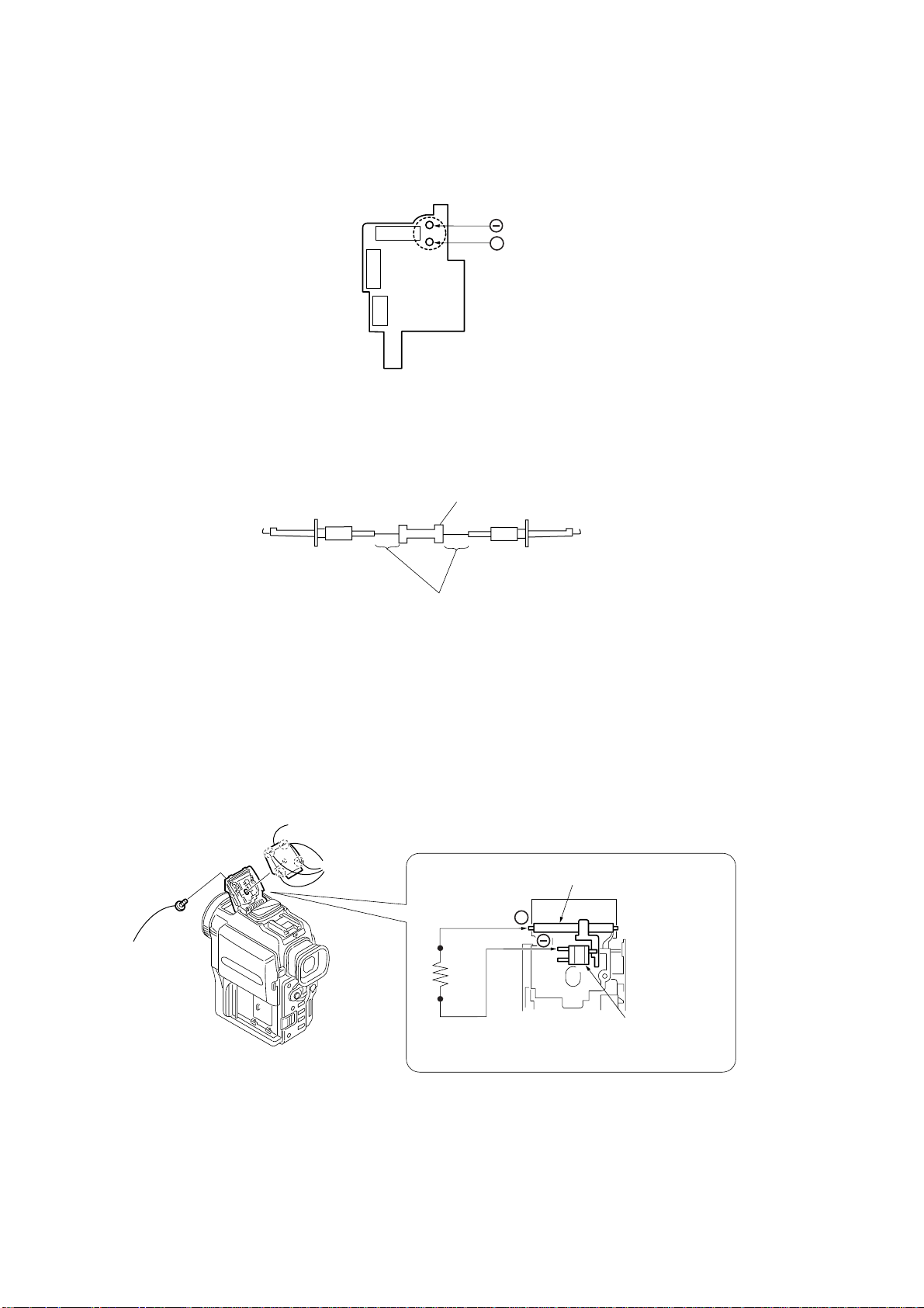
3. TO TAKE OUT A CASSETTE WHEN NOT EJECT (FORCE EJECT)
1 Refer to 2-2. to remove the jack ornamental plate.
2 Refer to 2-2. to remove the upper cabinet .
3 Refer to “2. HOW TO OPEN THE FLASH WHEN THE FLASH
DOESN’T OPEN” to open the flash.
4 Refer to 2-2. to remove the cabinet (L) assembly.
5 Refer to 2-2. to remove the microphone unit.
6 Refer to 2-3. to remove the EVF block.
7 Refer to 2-4. to remove the cabinet (R) assembly.
8 Refer to 2-7. to remove the IR window.
9 Refer to 2-7. to remove the MF ring.
0 Refer to 2-7. to remove the lens block.
qa Disconnect CN256 (27P) of VC-253 board.
qs Supply +4.5V from the DC power supply to the loading motor
and unload with a pressing the cassette compartment.
DC power supply
(+4.5Vdc)
: Unloading
: Loading
AI-021 board
Disconnect from CN256
— 5 —
AI-021 board
Loading motor
VC-253 board
4. DISCHARGING OF THE FLASHLIGHT POWER SUPPLY CAPACITOR
The capacitor (C2010) of the flash unit is charged up to the maximum 300V potential.
There is a danger of electric shock by this high voltage when the capacitor is handled by hand. The electric shock is caused by the charged
voltage which is kept without discharging when the main power of the unit is simply turned off. Therefore, the remaining voltage must be
discharged as described below.
C2010
FLASH UNIT
(30550MC)
4-1. PREPARING THE SHORT JIG
+
To preparing the short jig. a small clip is attached to each end of a resistor of 1kΩ/1W (1-215-869-11)
Wrap insulating tape fully around the reads of the resistor to prevent electric shock.
1 kΩ/1 W
Wrap insulating tape.
4-2. DISCHARGING THE CAP ACITOR
* Use either one of the following two procedure to discharge the capacitor.
< DISCHARGING THE CAPACITOR-1 >
1 Remove the power supply (Battery or AC power adaptor).
2 Refer to “2. HOW TO OPEN THE FLASH WHEN THE FLASH DOESN’T OPEN” to open the flash. (Page 5)
3 Remove the upper ST cabinet.
4 Short circuit between the anode 3 of the xenon lamp and the GND # terminal of the trigger transformer (L2010) with the short jig
about 10 seconds.
3
ST cabinet (upper)
2
1
Screw,
tapping
Remove the
four claws.
Short jig
Xenon tube
+
Trigger transformer
FLASH UNIT
< DISCHARGING THE CAPACITOR-2 >
1 Remove the power supply (Battery or AC power adaptor).
2 Short circuit between 3 and # terminal of the capacitor (C2010) with the short jig about 10 seconds.
— 6 —
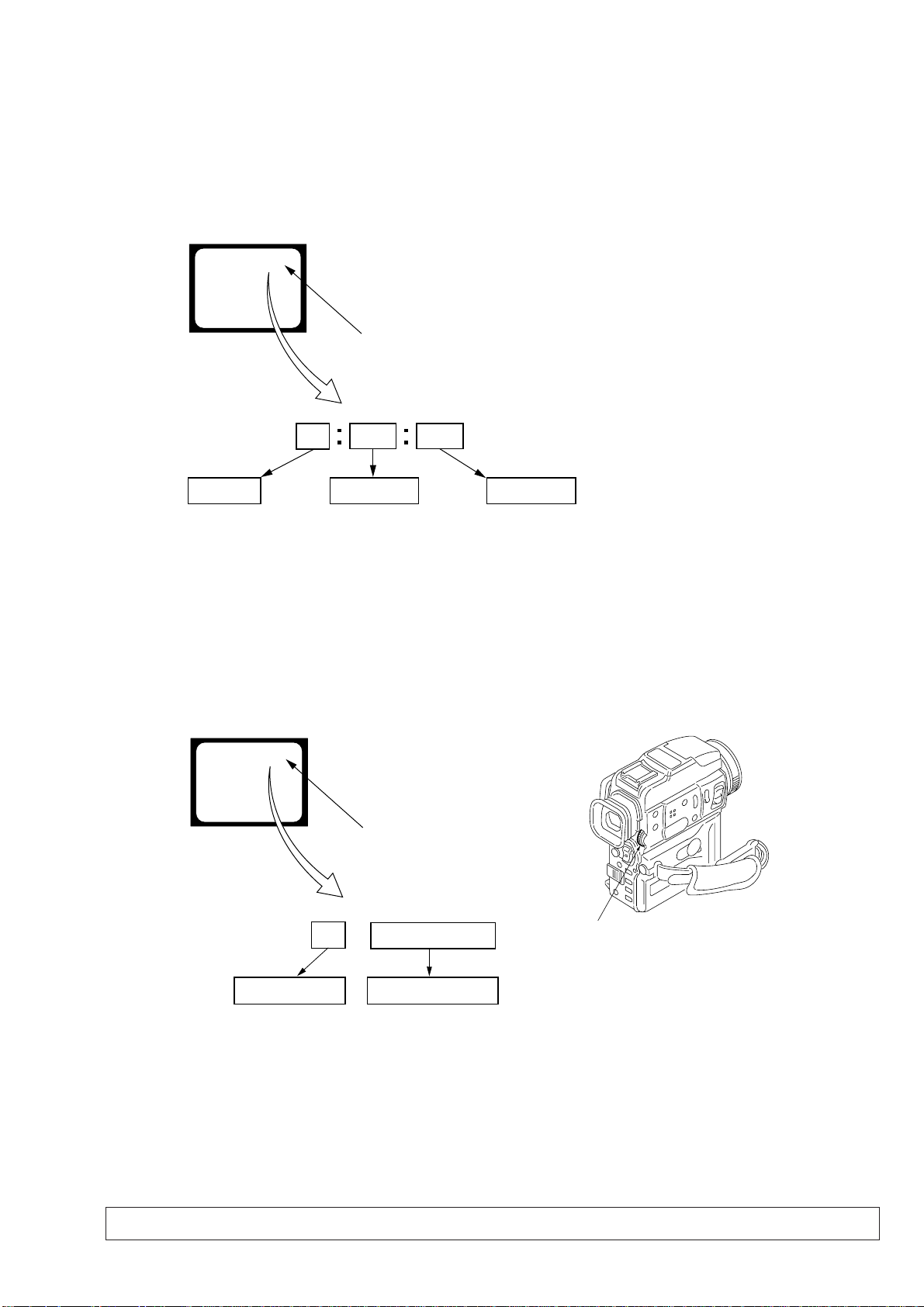
SELF-DIAGNOSIS FUNCTION
1. SELF-DIAGNOSIS FUNCTION
When problems occur while the unit is operating, the self-diagnosis
function starts working, and displays on the viewfinder or LCD
screen what to do. This function consists of two display; selfdiagnosis display and service mode display .
Details of the self-diagnosis functions are provided in the Instruction
manual.
Viewfinder or LCD screen
C : 3 1 : 1 1
Repaired by:
C : Corrected by customer
H : Corrected by dealer
E : Corrected by service
engineer
Blinks at 3.2Hz
3 1C
Block
Indicates the appropriate
step to be taken.
E.g.
31 ....Reload the tape.
32 ....T u r n o n power again.
1 1
2. SELF-DIAGNOSIS DISPLAY
When problems occur while the unit is operating, the counter of the
viewfinder or LCD screen consists of an alphabet and 4-digit
numbers, which blinks at 3.2 Hz. This 5-character display indicates
the “repaired by:”, “block” in which the problem occurred, and
“detailed code” of the problem.
Detailed Code
Refer to page 8.
Self-diagnosis Code Table.
3. SERVICE MODE DISPLAY
The service mode display shows up to six self-diagnosis codes shown in the past.
3-1. Display Method
While pressing the “STOP” key, set the switch from OFF to “VCR”, and continue pressing the “STOP” key for 5 seconds continuously. The
service mode will be displayed, and the counter will show the backup No. and the 5-character self-diagnosis codes.
Viewfinder or LCD screen
[3] C : 3 1 : 1 1
Lights up
[3]
Backup No.
Order of previous errors
C : 3 1 : 1 1
Self-diagnosis Codes
3-2. Switching of Backup No.
By rotating the control dial, past self-diagnosis codes will be shown in order. The backup No. in the [] indicates the order in which the
problem occurred. (If the number of problems which occurred is less than 6, only the number of problems which occurred will be shown.)
[1] : Occurred first time [4] : Occurred fourth time
[2] : Occurred second time [5] : Occurred fifth time
[3] : Occurred third time [6] : Occurred the last time
Control dial
3-3. End of Display
Turning OFF the power supply will end the service mode display.
Note: The “self-diagnosis display” data will be backed up by the coin-type lithium battery (BT1731) of the control switch block (FK-30550). When the
cabinet (L) assembly is removed, the “self-diagnosis display” data will be lost by initialization.
— 7 —

4. SELF-DIAGNOSIS CODE TABLE
Self-diagnosis Code
Repaired by:
C
C
C
C
C
C
C
C
C
C
C
C
C
C
C
C
C
C
C
C
C
C
C
E
E
E
E
Block
Function
04
21
22
31
31
31
31
31
31
31
31
31
31
31
31
32
32
32
32
32
32
32
32
61
61
62
62
Detailed
Code
00
00
00
10
11
20
21
22
23
24
30
40
42
10
11
20
21
22
23
24
30
40
42
00
10
00
01
Symptom/State
Non-standard battery is used.
Condensation.
Video head is dirty.
LOAD direction. Loading does not
complete within specified time
UNLOAD direction. Loading does not
complete within specified time
T reel side tape slacking when unloading
Winding S reel fault when counting the
rest of tape.
T reel fault.
S reel fault.
T reel fault.
FG fault when starting capstan.
FG fault when starting drum.
FG fault during normal drum operations.
LOAD direction loading motor time-
out.
UNLOAD direction loading motor
time-out.
T reel side tape slacking when
unloading.
Winding S reel fault when counting the
rest of tape.
T reel fault.
S reel fault.
T reel fault.
FG fault when starting capstan.
FG fault when starting drum
FG fault during normal drum
operations
Difficult to adjust focus
(Cannot initialize focus.)
Zoom operations fault
(Cannot initialize zoom lens.)
Steadyshot function does not work well.
(With pitch angular velocity sensor output
stopped.)
Steadyshot function does not work well.
(With yaw angular v elocity sensor output
stopped.)
Correction
Use the info LITHIUM battery.
Remove the cassette, and insert it again after one hour.
Clean with the optional cleaning cassette.
Load the tape again, and perform operations from the beginning.
Load the tape again, and perform operations from the beginning.
.
Load the tape again, and perform operations from the beginning.
Load the tape again, and perform operations from the beginning.
Load the tape again, and perform operations from the beginning.
Load the tape again, and perform operations from the beginning.
Load the tape again, and perform operations from the beginning.
Load the tape again, and perform operations from the beginning.
Load the tape again, and perform operations from the beginning.
Load the tape again, and perform operations from the beginning.
Remove the battery or power cable, connect, and perform
operations from the beginning.
Remove the battery or power cable, connect, and perform
operations from the beginning.
Remove the battery or power cable, connect, and perform
operations from the beginning.
Remove the battery or power cable, connect, and perform
operations from the beginning.
Remove the battery or power cable, connect, and perform
operations from the beginning.
Remove the battery or power cable, connect, and perform
operations from the beginning.
Remove the battery or power cable, connect, and perform
operations from the beginning.
Remove the battery or power cable, connect, and perform
operations from the beginning.
Remove the battery or power cable, connect, and perform
operations from the beginning.
Remove the battery or power cable, connect, and perform
operations from the beginning.
Inspect the lens block focus MR sensor (Pin 8,9 of CN1301 of
CD-285 board) when focusing is performed when the control dial
is rotated in the focus manual mode, and the focus motor drive circuit
(IC751 of VC-253 board) when the focusing is not performed.
Inspect the lens block zoom MR sensor (Pin ql,wa of CN1301 of
CD-285 board) when zooming is performed when the zoom lens is
operated and the zoom motor drive circuit (IC751 of VC-253 board)
when zooming is not performed.
Inspect pitch angular velocity sensor (SE1401 of VF-147 board)
peripheral circuits.
Inspect yaw angular velocity sensor (SE1431 of VF-147 board)
peripheral circuits.
— 8 —
1. MAIN PARTS
Note:
• Follow the disassembly procedure in the numerical order given.
• Items marked “*” are not stocked since they are seldom required for routine service.
Some delay should be anticipated when ordering these items.
• The parts numbers of such as a cabinet are also appeared in this section.
Refer to the parts number mentioned below the name of parts to order.
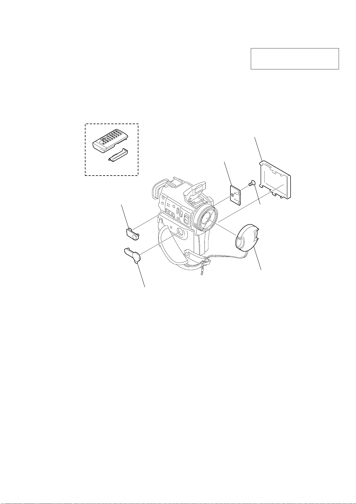
1. ORNAMENTAL PARTS
Remote commander (RMT-811)
1-475-950-21
CPC lid
3-063-500-01
Battery case lid
3-053-056-01
DCR-PC110E
The components identified by mark 0 or
dotted line with mark 0 are critical for safety.
Replace only with part number specified.
Battery cover
3-057-482-01
Jack cover (G)
3-063-468-01
Jack cover (S)
3-063-436-01
Screw (M1.7
lock ace, k3
3-057-437-01
Lens cap assembly
X-3949-944-1
×
2.5),
— 9 —
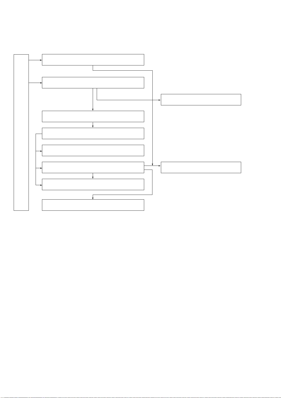
2. DISASSEMBLY
The following flow chart shows the disassembly procedure.
2-1. PD-134 board, Inverter transformer unit
2-2. Cabinet (L) block assembly
2-3. EVF block assembly
2-4. VTR overall section, Cabinet (R) block assembly
DCR-PC110E
2-5. Flash unit (MC), ST cabinet (lower)
2-9. Control switch block (PS30550),
Control switch block (FK30550)
2-6. FJ-027 board
2-7. CD-285 board, Lens section
2-8. AI-021, VC-253 boards, Mechanism deck
2-10. LCD hinge assembly
— 10 —
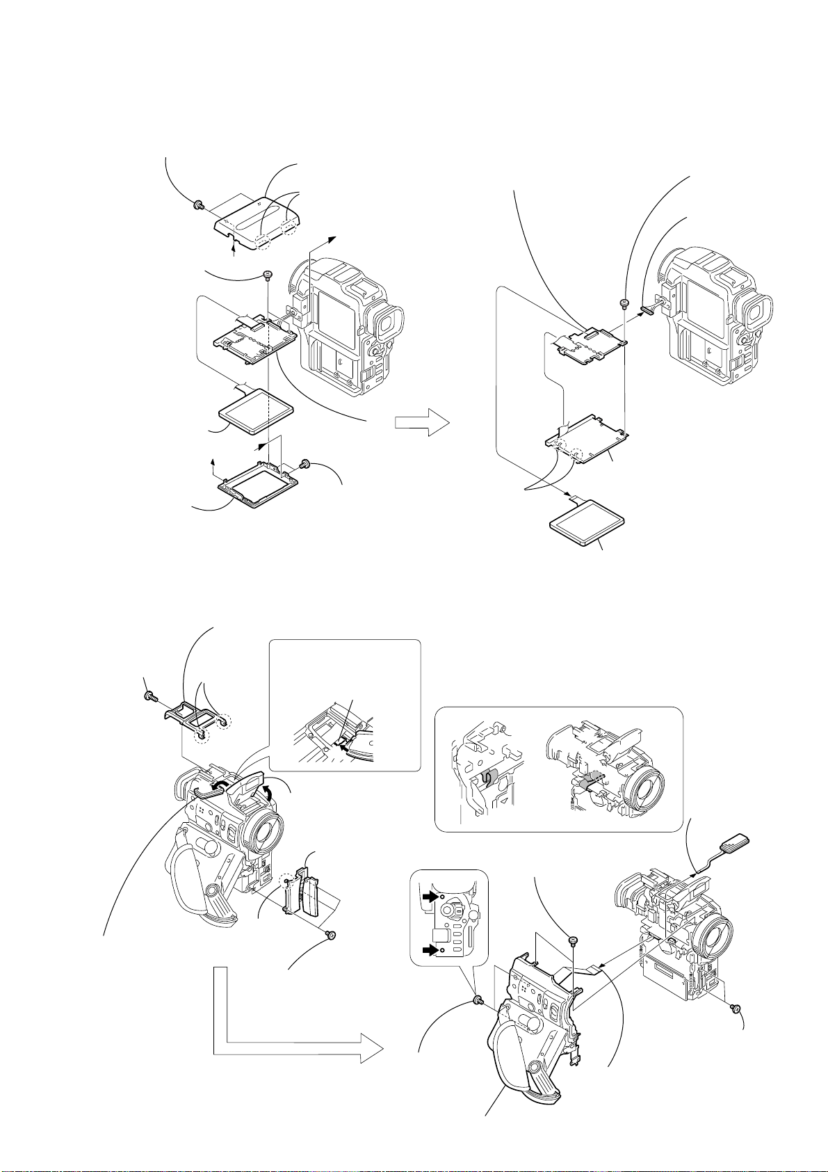
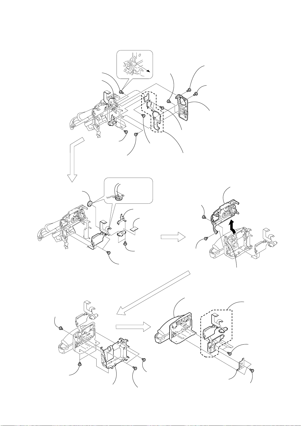
NOTE: F ollo w the disassembly procedure in the numerical order given.
P
D
-1
3
4
A
A
B
B
P
D
-1
3
4
2
Two claws
8
1
Harness
(PT-107) (16P)
3
LCD cabinet (R)
assembly
6
LCD cabinet (L)
assembly
5
T wo screws
(M1.7 × 2.5),
lock ace, p2
4
T wo screws
(M1.7 × 2.5),
lock ace, p2
3
Screw
(M1.7 × 2.5),
lock ace, p2
1
T wo screws
(M1.7 × 2.5),
lock ace, p2
7
Liquid crystal
indicator module
4
Two claws
6
PD-134 board,
Inverter transformer unit
2
Liquid crystal
indicator module (24P)
5
Back light
(Cold cathode fluorescent tube),
BL shield sheet (N)
4
Control switch block
(FK30550) (51P)
5
Cabinet (L) block assembly
Lock plate
A
B
9
Jack ornamental
plate assembly
3
Cabinet (upper)
1
Screw
(M1.7 × 4),
lock ace, p2
2
Two claws
8
Claw
1
T wo screws
(M1.7 × 2.5),
lock ace, p2
2
Two screws
(M1.7 × 2.5),
lock ace, p2
3
T wo screws
(M1.7 × 2.5),
lock ace, p2
7
Three screws
(M1.7 × 2.5),
lock ace, p2
5
Push the lock plate in the
direction of the arrow B
to open the flash unit.
Routing of the flexible board of the Operation
switch block (FK30550) when attaching the
Cabinet (L) block.
4
Move the microphone block
in the direction of the arrow A.
6
Microphone unit
(5P)
6
Open the flash unit
2-1. PD-134 BOARD, INVERTER TRANSFORMER UNIT
2-2. CABINET (L) BLOCK ASSEMBLY
— 11 —
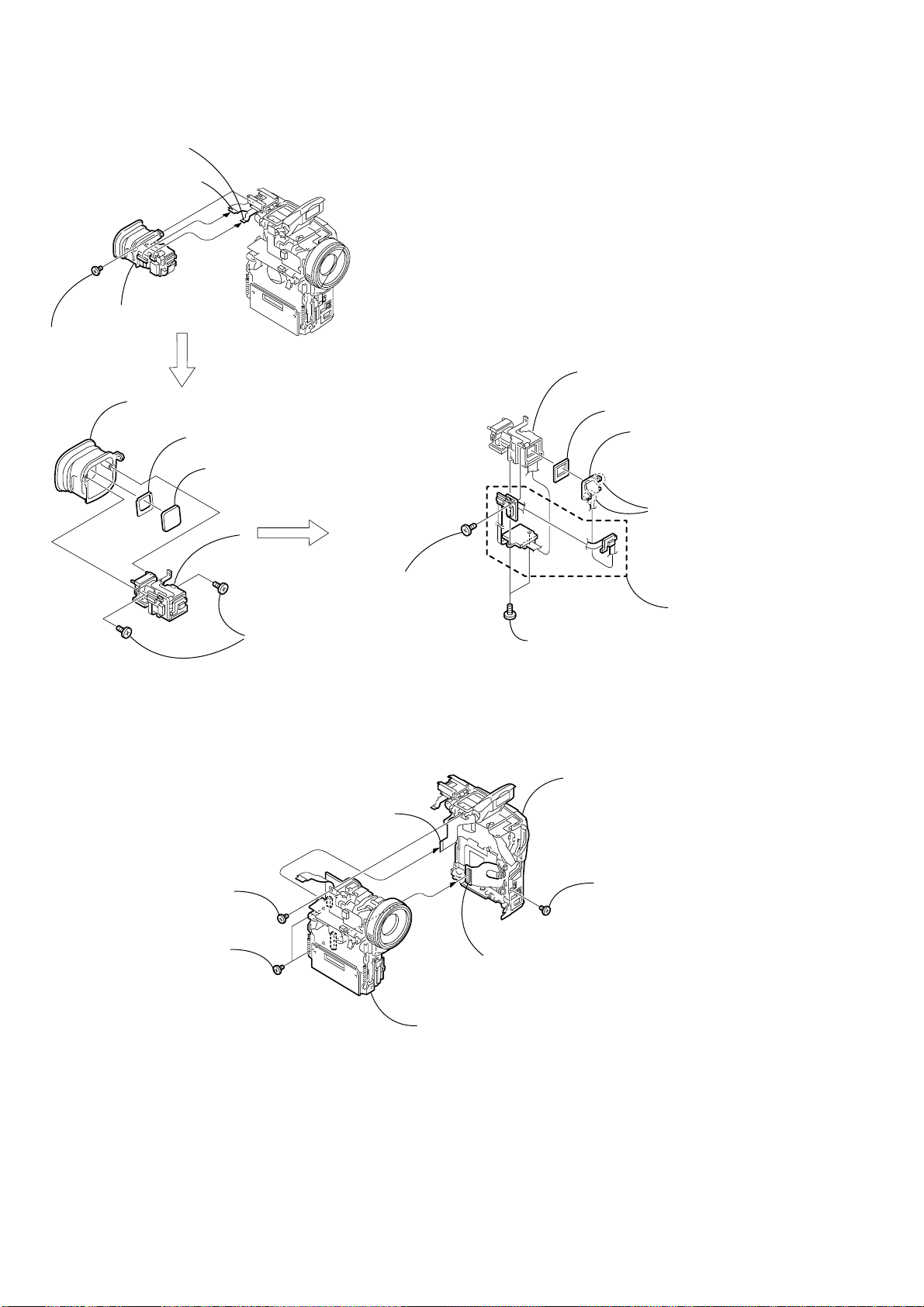
y
2-3. EVF BLOCK ASSEMBLY
3
FP-252 flexible board
(10P)
2
FP-253 flexible board
(33P)
4
EVF block assembly
1
Screw
(M1.7 × 2.5),
lock ace, p2
4
EVF cup assembly
3
VF spacer
2
VF cover
5
7
Lens holder assembly
6
LCD cushion (B)
5
Light guide plate block,
BL cushion (B),
BL holder
3
Two claws
1
Precision screw
1
Two tapping screws
(M1.7 × 5)
(dia, 1.7
×
4)
2-4. VTR OVERALL SECTION, CABINET (R) BLOCK ASSEMBLY
5
FP-255 flexible board
(27P)
1
Screw
(M1.7
lock ace, p2
2
(M1.7 × 2.5),
lock ace, p2
×
2.5),
T wo screws
4
FJ-027 board (70P)
6
VTR overall section
2
Two precision screws
(dia, 1.7
×
4)
7
Cabinet (R) block assembl
3
Screw
(M1.7 × 2.5),
lock ace, p2
4
VF-147 board
— 12 —
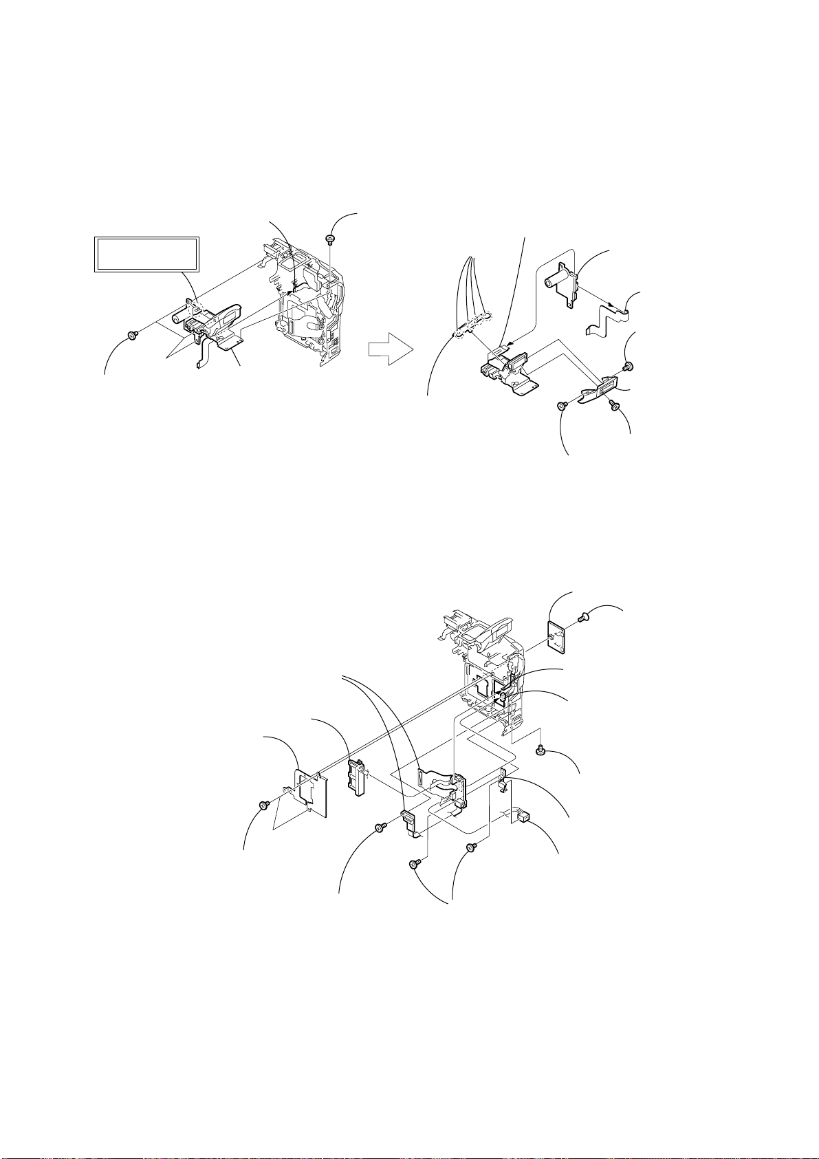
2-5. FLASH UNIT (MC), ST CABINET (LOWER)
Note: The power capacitor (C2010) of the flash unit is charged to the high tension voltage as high as 300 V at a maximum.
You will get electrical shock when you touch the terminal of the charged capacitor. The charged potential remains
even after the main power of the machine is turned off.
Discharge the remaining power in the capacitor referring to Service Note (page 6).
3
Control switch block
(ME30550) (7P)
(Note)
Capacitor terminal
2
Three screws
(M1.7 × 2.5),
lock ace, p2
4
(Note)
1
Screw
(M1.7
lock ace, p2
×
2.5),
0
(upper)
9
Four
claws
ST cabinet
6
Flash unit (ST) (33P)
qa
Screw
(M1.7 × 2.5),
lock ace, p2
7
Flash unit (MC)
5
FP-255 flexible board
(27P)
qs
Screw
(M1.7 × 2.5),
lock ace, p2
qd
ST cabinet (lower)
8
Precision screw
(dia, 1.7
×
4)
2-6. FJ-027 BOARD
5
Battery Terminal board
4
T erminal retainer
qd
FJ-027 board
3
T wo screws
(M1.7 × 2.5),
lock ace, p2
6
Screw
(M1.7 × 4),
lock ace, p2
7
T wo screws
(M1.7 × 2.5),
lock ace, p2
2
CPC lid
1
Screw
(M1.7 × 2.5),
lock ace, k3
qa
FP-251 flexible board
(6P)
qs
Harness
(PT-107) (6P)
8
Screw
(M1.7 × 2.5),
lock ace, p2
9
DC frame
0
DC-IN connector
— 13 —
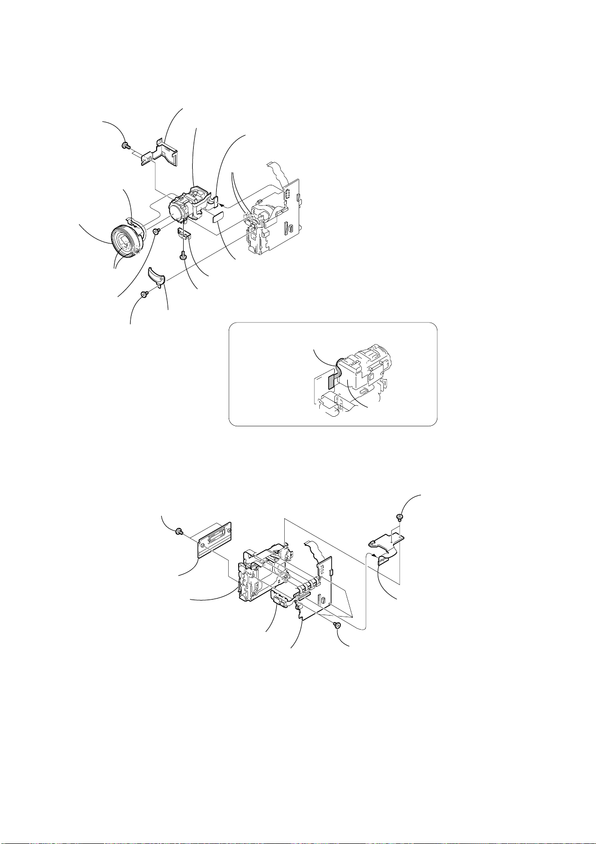
2-7. CD-285 BOARD, LENS SECTION
0
9
Two tapping screws
(B1.7 × 3)
3
Control switch block
(MF30550) (8P)
CD shield case assembly
qf
Lens section
8
Two
claws
6
CD-285 board (60P)
5
MF base assembly,
Control switch block
(MF30550)
qd
Shield sheet metal
4
Two dowels
7
Screw
(M1.7 × 2.5),
lock ace, p2
2
IR window
1
Screw
(M1.7 × 2.5),
lock ace, p2
assembly
qs
(B1.7
assembly
qa
Lens frame
Tapping (B) screw
×
3)
PRECAUTION DURING LENS INSTALLATION
Check that the flexible board is laid
along with the CD shield case.
2-8. AI-021, VC-253 BOARDS, MECHANISM DECK
AI-021
VC-253
CD shield case
6
T wo screws
(M1.7
lock ace, p2
7
Cassette compartment
cover
8
Mechanism deck,
MD frame assembly,
MK sheet metal
×
2.5),
4
FP-256 flexible board
5
VC-253 board
VC 253
AI-021
3
Three screws
×
(M1.7
2.5),
lock ace, p2
1
T wo screws
(M1.7
×
lock ace, p2
2
AI-021 board (100P)
2.5),
— 14 —
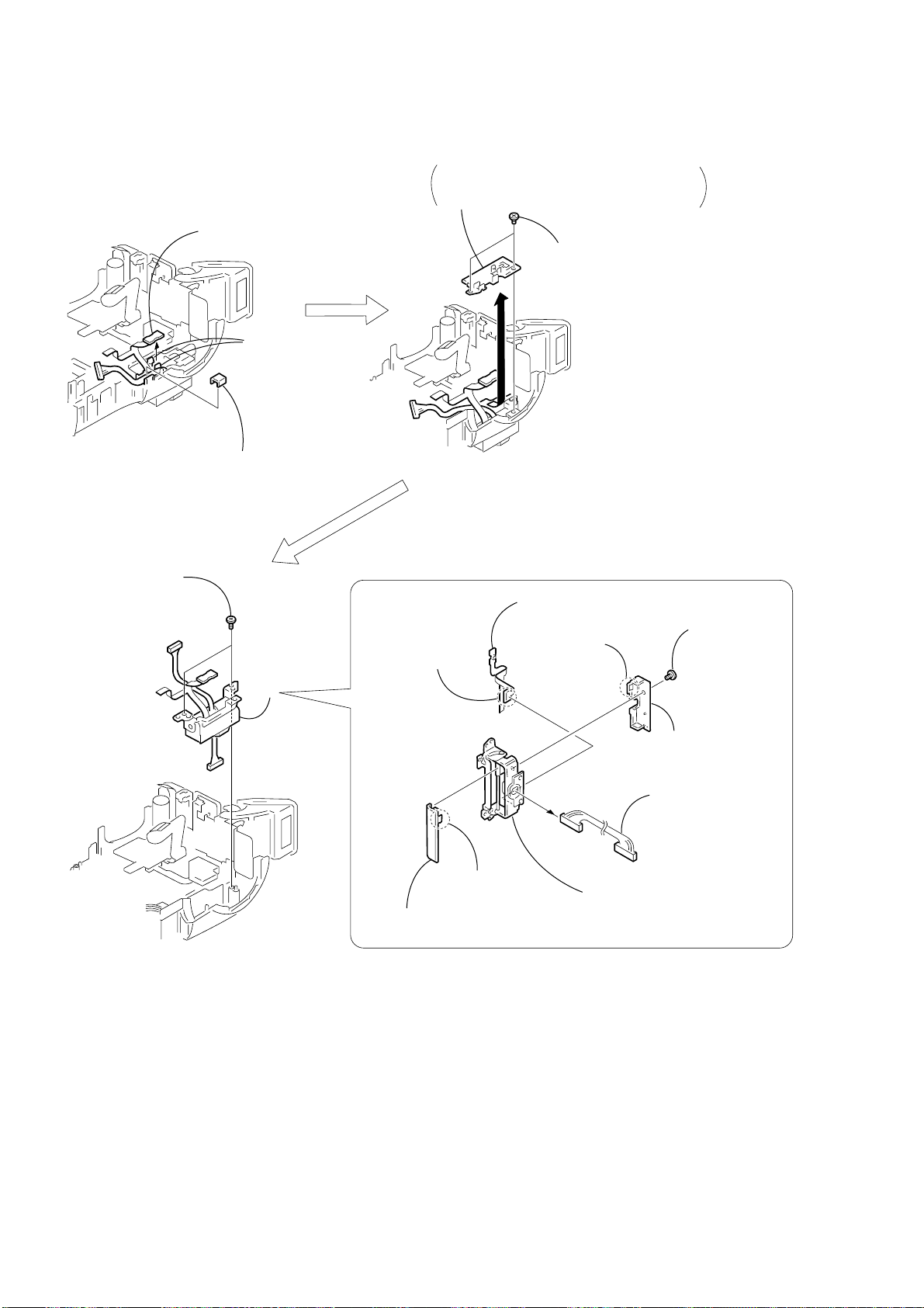
2-9. CONTROL SWITCH BLOCK (PS30550), CONTROL SWITCH BLOCK (FK30550)
9
5
Screw
(M1.7 × 4),
lock ace, p2
3
Control switch block
(FK30550) (17P)
1
(M1.7 × 2.5),
lock ace, p2
6
Speaker
Three screws
8
Screw
(M1.7 × 2.5),
lock ace, p2
5
Remove the
two solderings
4
SP retainer plate
Screw
(M1.7 × 2.5),
lock ace, p2
2
Screw
(M1.7 × 2.5),
lock ace, p2
6
Screw
(M1.7 × 4),
lock ace, p2
7
(dia, 1.7
q;
4
T wo screws
(M1.7 × 4),
lock ace, p2
qa
Control switch block
(PS30550)
1
Screw
(M1.7 × 2.5),
lock ace, p2
Precision screw
×
Cabinet (rear) assembly
4)
4
Cabinet (L)
4
Screw
(M1.7 × 2.5),
lock ace, p2
2
FK flexible guard
3
T wo screws
(M1.7 × 2.5),
lock ace, p2
1
T wo screws
(M1.7 × 2.5),
lock ace, p2
2
Screw
(M1.7
lock ace, p2
×
2.5),
4
Cabinet (G) assembly
3
Remove the Cabinet (L) assembly
while taking care so that it must
not be caught by other parts.
5
Control switch block
(FK30550)
3
Four precision
screws
(dia, 1.7
×
4)
1
T wo screws
(M1.7 × 2.5),
lock ace, p2
5
G frame assembly
2
Screw
(M1.7 × 2.5),
lock ace, p2
3
Two precision screws
(dia, 1.7
×
4)
— 15 —
2
MS connector
retainer
1
Three precision
screws
(dia, 1.7
×
4)
2-10. LCD HINGE ASSEMBLY
2
FP-251 flexible board
1
3
Harness clip
Two claws
5
Blind plate assembly
Remove it while taking care so that it must not
be caught by the flexible board and harnesses,
by pulling it in the direction of the arrow.
4
T wo screws
(M1.7 × 2.5),
lock ace, p2
6
T wo screws
(M1.7 × 4),
lock ace, p2
7
7
Peel off the
adhesive side.
5
Hinge cover (front)
4
8
FP-251 flexible board
Claw
2
Claw
9
LCD hinge assembly
1
Screw
(M1.7
lock ace, p2
3
Hinge cover (rear)
6
Harness (PT-107)
×
2.5),
— 16 —
3. REPAIR PARTS LIST
3-1. EXPLODED VIEWS
NOTE:
• -XX, -X mean standardized parts, so they may
have some differences from the original one.
• Items marked “*” are not stocked since they
are seldom required for routine service. Some
delay should be anticipated when ordering these
items.
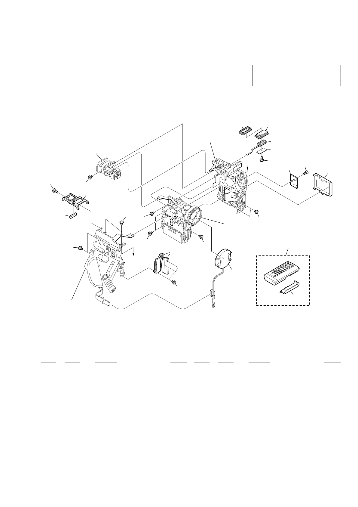
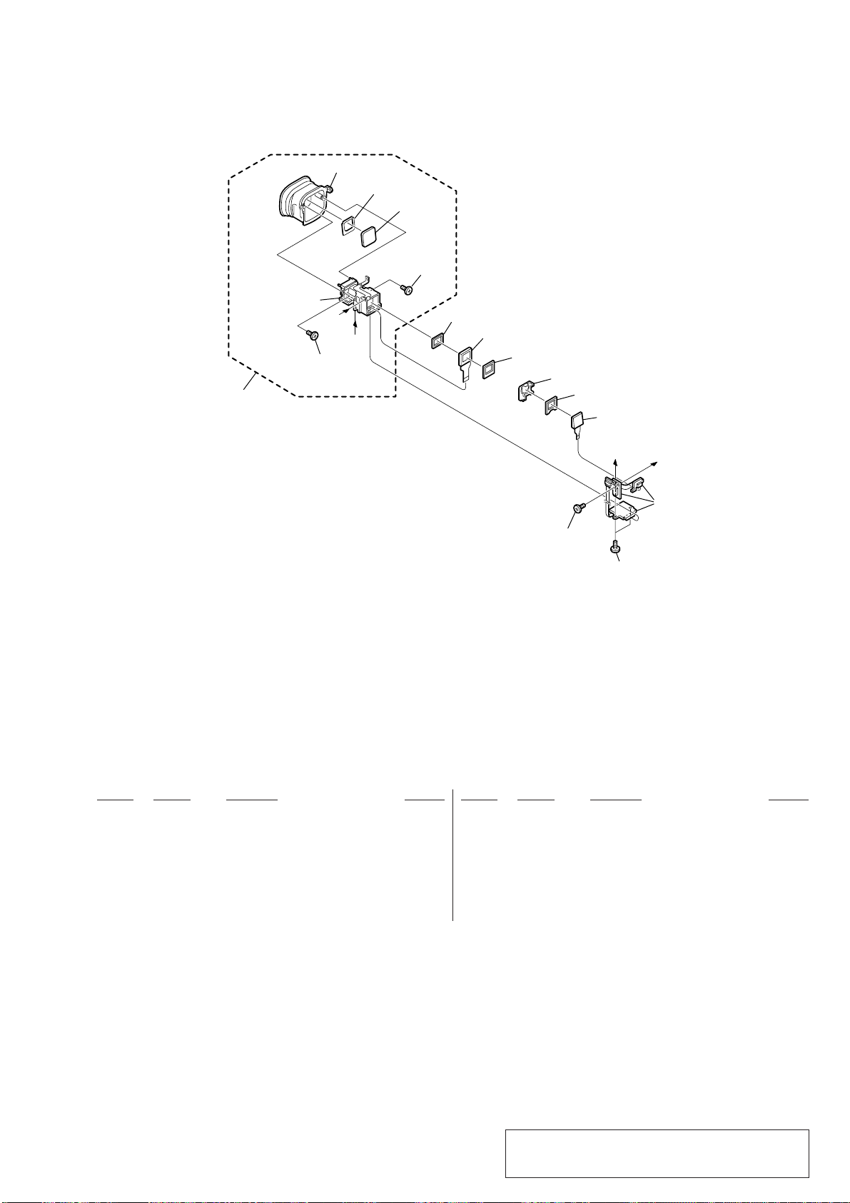
3-1-1. OVERALL SECTION
• The mechanical parts with no reference number
in the exploded views are not supplied.
The components identified by mark 0 or
dotted line with mark 0 are critical for safety.
Replace only with part number specified.
EVF section
(See page 19)
5
15
2
Cabinet (L) section
(See page 18)
Cabinet (R) section-1, 2
(See page 21 to 22)
6
7
MIC901
8
A
9
10
11
12
2
4
2
2
VTR overall section
(See page 20)
2
2
2
13
3
A
1
2
14
Ref. No. Part No. Description Remarks Ref. No. Part No. Description Remarks
1 X-3949-944-1 CAP ASSY, LENS
2 3-989-735-11 SCREW (M1.7), LOCK ACE, P2
3 X-3951-068-1 PLATE ASSY, JACK ORNAMENTAL
4 3-063-512-01 CABINET (UPPER)
5 3-989-735-31 SCREW (M1.7), LOCK ACE, P2
6 3-063-513-01 DAMPER, MICROPHONE
7 X-3950-923-1 GRILLE ASSY, MICROPHONE
8 3-063-514-01 LID,MICROPHONE (REAR)
9 3-914-366-01 SCREW (DIA. 1.7X4), PRECISION
10 3-063-500-01 LID,CPC
* 11 3-057-437-01 LOCK ACE (M1.7)
12 3-057-482-01 COVER, BATTERY
13 1-475-950-21 REMOTE COMMANDER (RMT-811)
14 3-053-056-01 LID,BATTERY CASE
* 15 3-065-093-01 CUSHION, ACOUSTIC ISOLATION
MIC901 1-476-282-11 MICROPHONE UNIT
— 17 —
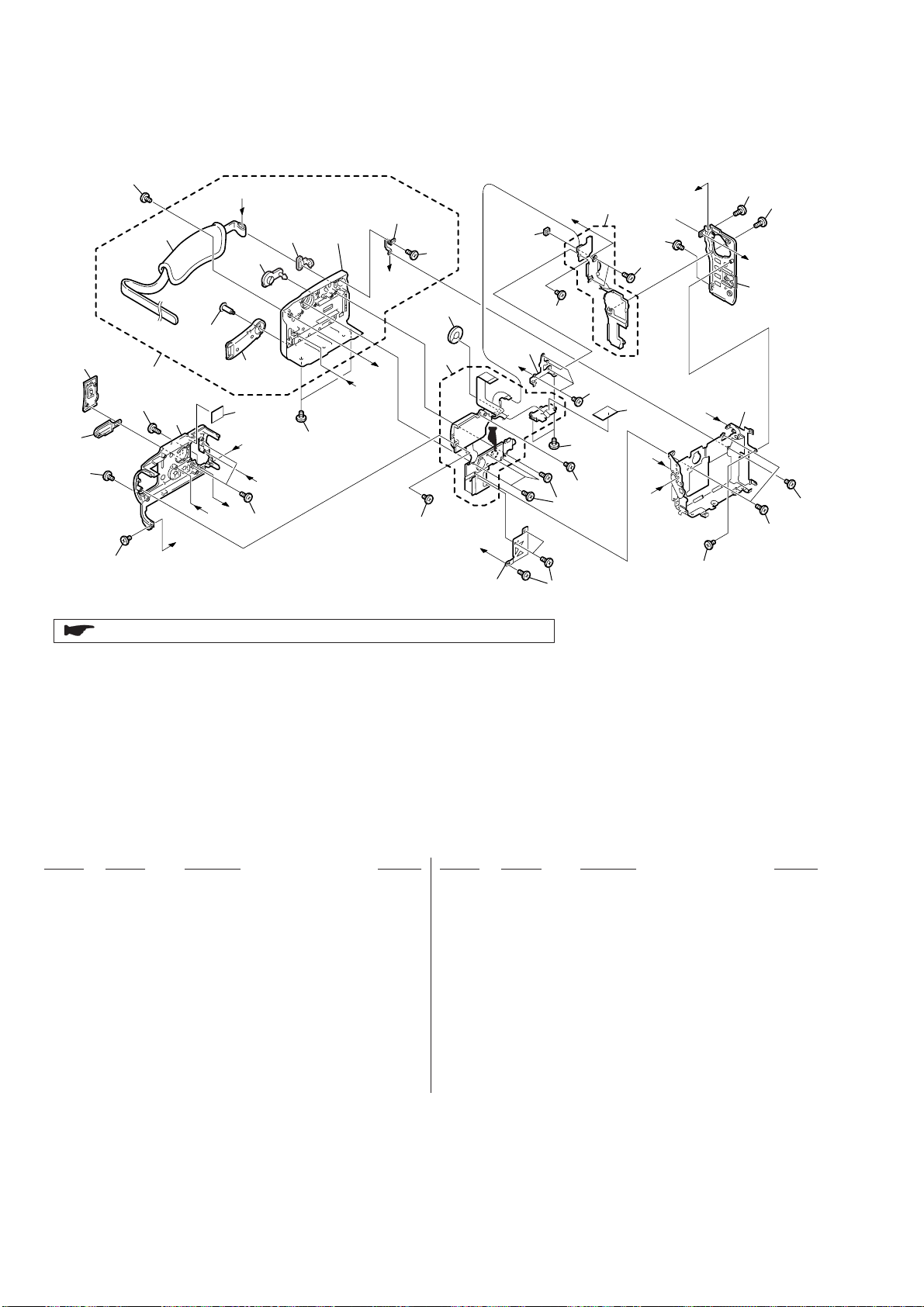
3-1-2. CABINET (L) SECTION
54
55
53
53
53
56
58
61
57
D
60
I
F
A
73
59
E
62
51
H
63
not
supplied
53
B
C
A
64
53
65
SP901
66
B
52
I
72
67
53
51
51
H
53
53
53
68
71
56
C
D
53
F
E
G
53
56
51
G
69
70
53
51
: BT1731 (Lithium battery) Control switch block (FK30550) on the mount position.
Ref. No. Part No. Description Remarks Ref. No. Part No. Description Remarks
51 3-914-366-01 SCREW (DIA. 1.7X4), PRECISION
52 3-063-496-01 RETAINER, MS CONNECTOR
53 3-989-735-11 SCREW (M1.7), LOCK ACE, P2
54 3-063-463-01 COVER (L), JACK
55 X-3951-074-1 PLATE ASSY, ORNAMENTAL
56 3-989-735-31 SCREW (M1.7), LOCK ACE, P2
57 3-063-460-11 CABINET (L)
58 X-3951-072-1 CABINET (G) ASSY
59 X-3950-913-1 BELT(FRONT) ASSY, GRIP
60 3-064-335-01 SCREW (M3),SPECIAL HEAD (STEP)
61 3-062-141-01 BELT, GRIP
62 3-063-436-01 COVER (S), JACK
63 3-063-468-01 COVER (G), JACK
64 3-062-129-01 BRACKET (REAR), BELT
65 3-713-791-71 SCREW (M1.7X4)
66 not supplied SWITCH BLOCK, CONTROL (FK30550)
* 67 3-063-483-01 PLATE, SP RETAINER
68 1-476-283-11 SWITCH BLOCK, CONTROL (PS30550)
69 X-3951-069-1 CABINET (REAR) ASSY
70 X-3950-916-2 FRAME ASSY, G
* 71 3-064-657-01 GUARD, FK FLEXIBLE
* 72 3-057-438-11 CUSHION, LIGHT INTERCEPTION
* 73 3-066-201-01 INSULATING SHEET, MT
SP901 1-529-674-11 SPEAKER (16MM)
— 18 —
3-1-3. EVF SECTION
107
not supplied
108
111
A
B
110
109
108
106
LCD902
105
104
103
LED901
B
A
102
101
101
Ref. No. Part No. Description Remarks Ref. No. Part No. Description Remarks
101 3-914-366-01 SCREW (DIA. 1.7X4), PRECISION
102 not supplied VF-147 BOARD, COMPLETE
103 3-062-205-11 CUSHION (B), BL
104 3-063-517-01 HOLDER, BL
* 105 3-063-520-01 CUSHION (B), LCD
108 3-713-791-41 SCREW (M1.7X5), TAPPING
* 109 3-063-450-01 COVER, VF
* 110 3-063-451-01 SPACER, VF
111 X-3951-035-1 CUP ASSY, EVF (SERVICE)
LCD902 not supplied LCX033AK-J
* 106 3-063-519-01 CUSHION (A), LCD
107 X-3950-912-1 HOLDER ASSY, LENS
0 LED901 not supplied BLOCK, LIGHT GUIDE PLATE (0.44)
Note : The components identified by mark 0 or dotted
— 19 —
line with mark 0 are critical for safety.
Replace only with part number specified.
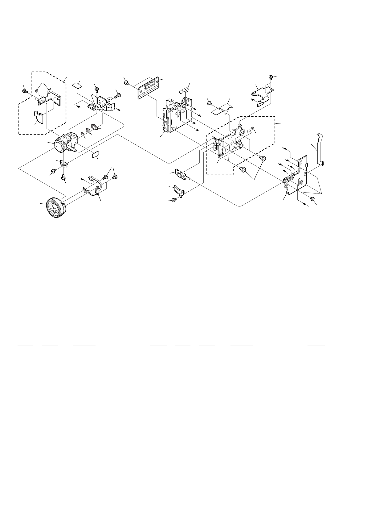
3-1-4. VTR OVERALL SECTION
154
not
supplied
not
supplied
157
153
156
155
160
154
174
G
158
G
154
161
159
173
IC1251
152
162
151
155
F
163
Mechanism deck
166
167
155
171
C
A
155
B
D
not
supplied
172
164
E
168
AI-021
not
supplied
C
169
155
165
F
A
D
B
VC 253
170
E
155
Ref. No. Part No. Description Remarks Ref. No. Part No. Description Remarks
151 3-914-366-01 SCREW (DIA. 1.7X4), PRECISION
152 1-476-285-11 SWITCH BLOCK, CONTROL (MF30550)
153 X-3950-921-1 BASE ASSY, MF
154 3-695-653-11 SCREW (1.7X3), TAPPING (B)
155 3-989-735-11 SCREW (M1.7), LOCK ACE, P2
156 3-063-504-01 FRAME, LENS
157 not supplied DEVICE, LENS LSV-690B
158 not supplied FILTER BLOCK, OPTICAL (OFB-04-21)
159 not supplied RUBBER (W), SEAL
* 160 X-3951-034-1 CASE ASSY, CD SHIELD
161 not supplied CD-285P BOARD, COMPLETE
162 3-318-203-11 SCREW (B1.7X6), TAPPING
163 3-059-722-01 COVER, CASSETTE COMPARTMENT
164 not supplied AI-021 BOARD, COMPLETE
165 X-3950-918-1 FRAME ASSY, MD
166 not supplied FP-256 BOARD, COMPLETE
167 X-3950-919-1 WINDOW ASSY, IR
168 3-059-718-01 SCREW (M1.4X1.5)
169 not supplied VC-253 BOARD, COMPLETE (SERVICE)
170 1-679-432-11 FP-253 FLEXIBLE BOARD
171 3-064-338-01 TAPE, DF
* 172 3-065-180-01 SHEET METAL, MK
* 173 X-3951-117-1 SHEET METAL ASSY, SHIELD
* 174 3-064-657-01 GUARD, FK FLEXIBLE
IC1251 not supplied CCD BLOCK ASSY (CCD IMAGER)
— 20 —
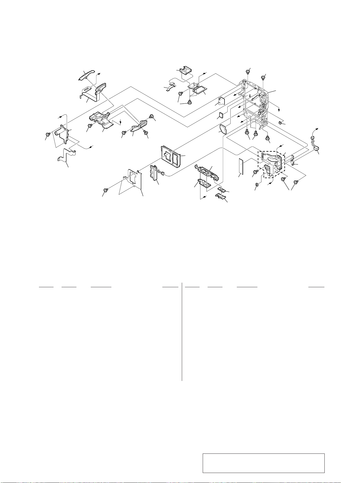
3-1-5. CABINET (R) SECTION-1
A
A
B
G
D
F
F
C
B
C
G
D
E
E
BT901
201
202
203
205
204
206
207
208
209
210
211
212
213
214
215
216
217
223
224
225
207
207
207
219
207
207
207
207
207
207
218
220
221
219
226
222
J901
Cabinet (R) section-2
(See page 22)
Ref. No. Part No. Description Remarks Ref. No. Part No. Description Remarks
201 3-062-193-01 SLIDER, EJECT KNOB
202 3-062-192-01 KNOB, EJECT
203 X-3950-925-1 FRAME ASSY, BOTTOM
204 3-062-191-01 SCREW, TRIPOD
205 X-3951-073-1 HOLDER ASSY, BATTERY
206 3-063-501-01 RETAINER, TERMINAL
207 3-989-735-11 SCREW (M1.7), LOCK ACE, P2
208 1-679-433-11 FP-255 FLEXIBLE BOARD
0 209 not supplied FLASH UNIT (MC)
0 211 not supplied FLASH UNIT (ST)
210 X-3951-036-1 STROBOSCOPE ASSY
212 3-063-510-11 CABINET (UPPER), ST
213 3-063-511-01 CABINET (LOWER), ST
214 3-914-366-01 SCREW (DIA. 1.7X4), PRECISION
215 1-679-431-11 FP-252 FLEXIBLE BOARD
216 1-785-594-11 CONNECTOR (HOT SHOE), OUTER
217 3-063-509-01 FRAME, SHOE
* 218 3-063-516-01 CLIP, HARNESS
219 3-989-735-31 SCREW (M1.7), LOCK ACE, P2
220 not supplied FJ-027 BOARD, COMPLETE
221 3-063-502-01 FRAME, DC
* 222 3-057-438-11 CUSHION, LIGHT INTERCEPTION
223 3-063-506-01 RUBBER, LENS
224 3-064-343-01 SHEET (B), INSULATING
225 3-064-341-01 SHEET, CL RADIATION
* 226 3-064-337-01 SHEET, CN RADIATION
BT901 1-694-493-21 TERMINAL BOARD, BATTERY
J901 1-815-005-11 CONNECTOR, DC-IN
— 21 —
Note : The components identified by mark 0 or dotted
line with mark 0 are critical for safety.
Replace only with part number specified.
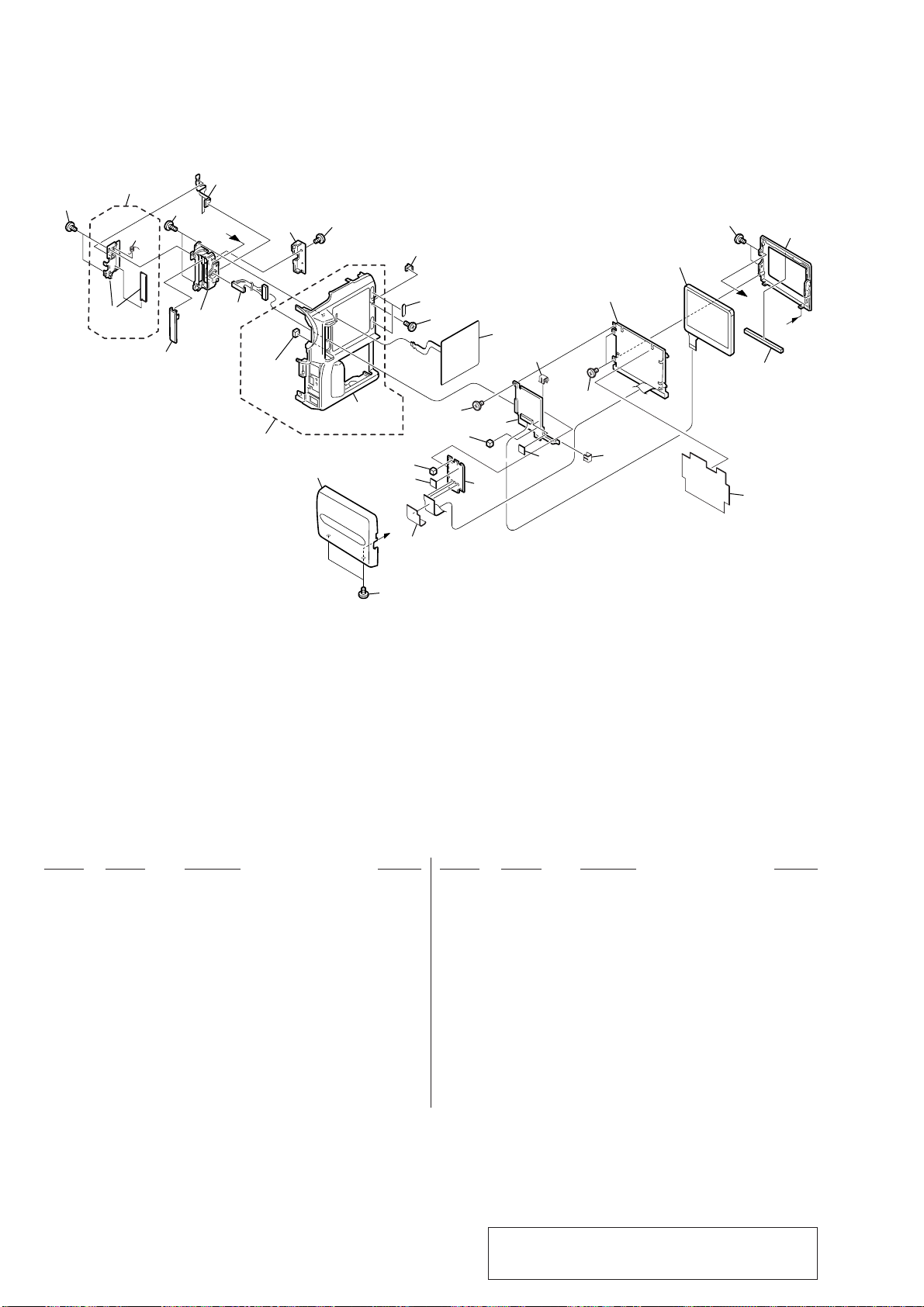
3-1-6. CABINET (R) SECTION-2
251
271
272
not
supplied
265
270
266
269
B
267
268
not
supplied
264
259
251
not
supplied
251
256
274
A
258
263
262
261
251
256
255
257
260
254
PD-134
274
ND901
251
254
LCD901
251
252
B
A
273
253
Ref. No. Part No. Description Remarks Ref. No. Part No. Description Remarks
251 3-989-735-11 SCREW (M1.7), LOCK ACE, P2
252 X-3950-909-1 CABINET (L) ASSY, LCD
253 3-060-704-01 SHEET (N), BL SHIELD
* 254 3-051-232-01 CLIP, PCB
255 not supplied PD-134 BOARD, COMPLETE
256 3-064-476-01 SPACER (T5), PD
0 257 not supplied TRANSFORMER UNIT, INVERTER
* 258 3-062-196-01 SHEET, BL INSULATING
259 X-3951-067-1 CABINET (R) ASSY, LCD
260 1-476-250-21 SWITCH BLOCK, CONTROL (ME30550)
261 3-914-366-01 SCREW (DIA. 1.7X4), PRECISION
* 262 3-064-473-01 CUSHION, PANEL
263 3-063-499-01 BASE, LCD LOCK
— 22 —
264 X-3951-071-1 CABINET (R) ASSY
265 3-063-497-01 COVER (FRONT), HINGE
266 X-3950-746-1 HINGE ASSY, LCD
267 1-960-799-11 HARNESS (PT-107)
268 3-063-498-01 COVER (REAR), HINGE
269 1-679-430-21 FP-251 FLEXIBLE BOARD
270 3-989-735-31 SCREW (M1.7), LOCK ACE, P2
271 X-3950-911-1 PLATE ASSY, BLIND
* 272 3-055-323-01 SPRING (MK), TORSION
* 273 3-064-677-01 SHEET,PANEL LIGHT INTERCEPTION
274 3-062-195-01 SPACER, PD (T5)
LCD901 not supplied ACX300CK-J
0 ND901 not supplied TUBE, FLUORESCENT, COLD CATHODE (2.5)
Note : The components identified by mark 0 or dotted
line with mark 0 are critical for safety.
Replace only with part number specified.
2. GENERAL
DCR-PC110E
This section is extracted
from instruction manual.
— 23 —
 Loading...