


Sony DCR-PC110, DCR-PC110E Service Manual
DCR-PC110/PC110E
RMT-811
Ver 1.0 2000. 09
SERVICE MANUAL
SERVICE MANUAL
Level 2
Photo : DCR-PC110
RMT-811
On the VC-253 board
This service manual provides the information that is premised the
circuit board replacement service and not intended repair inside the
VC-253 board.
Therefore, schematic diagram, printed wiring board and electrical parts
list of the VC-253 board are not shown.
The following pages are not shown.
Printed wiring board......................... Pages 4-11 to 4-14
Schematic diagram .......................... Pages 4-15 to 4-52
Electrical parts list............................ Pages 6-16 to 6-26
US Model
Canadian Model
Korea Model
DCR-PC110
AEP Model
UK Model
Australian Model
Chinese Model
DCR-PC110E
E Model
Hong Kong Model
Tourist Model
DCR-PC110/PC110E
J MECHANISM
For MECHANISM ADJUSTMENTS, refer to the
“DV MECHANICAL ADJUSTMENT MANUAL
J MECHANISM ” (9-929-807-11).
DCR-PC110 : NTSC model
DCR-PC110E : PAL model
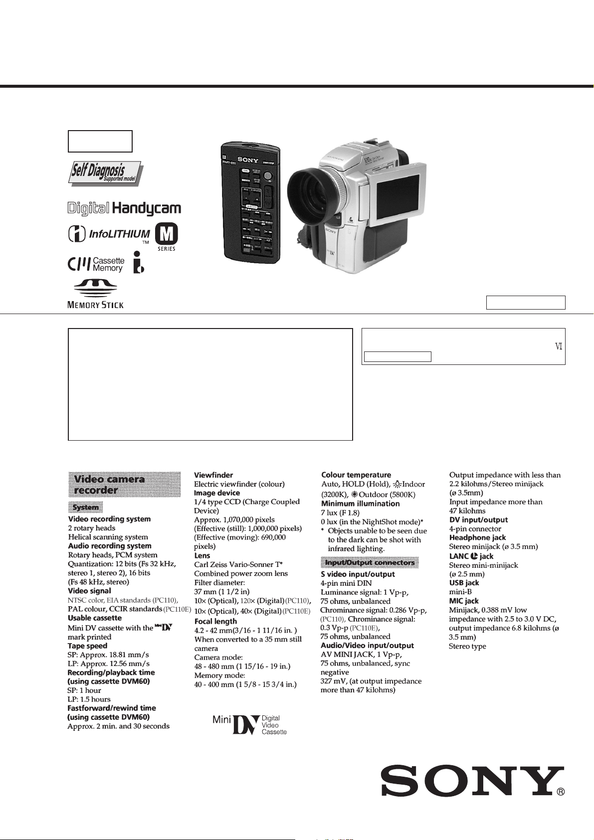
SPECIFICATIONS
— Continued on next page —
DIGITAL VIDEO CAMERA RECORDER
SAFETY-RELATED COMPONENT WARNING!!
COMPONENTS IDENTIFIED BY MARK 0 OR DOTTED LINE WITH
MARK 0 ON THE SCHEMATIC DIAGRAMS AND IN THE PARTS
LIST ARE CRITICAL TO SAFE OPERATION. REPLACE THESE
COMPONENTS WITH SONY PARTS WHOSE PART NUMBERS
APPEAR AS SHOWN IN THIS MANUAL OR IN SUPPLEMENTS
PUBLISHED BY SONY.
SAFETY CHECK-OUT
After correcting the original service problem, perform the following
safety checks before releasing the set to the customer.
ATTENTION AU COMPOSANT AYANT RAPPORT
À LA SÉCURITÉ!
LES COMPOSANTS IDENTIFÉS P AR UNE MARQUE 0 SUR LES
DIAGRAMMES SCHÉMA TIQUES ET LA LISTE DES PIÈCES SONT
CRITIQUES POUR LA SÉCURITÉ DE FONCTIONNEMENT. NE
REMPLACER CES COMPOSANTS QUE PAR DES PIÈSES SONY
DONT LES NUMÉROS SONT DONNÉS DANS CE MANUEL OU
DANS LES SUPPÉMENTS PUBLIÉS PAR SONY.
1. Check the area of your repair for unsoldered or poorly-soldered
connections. Check the entire board surface for solder splashes
and bridges.
2. Check the interboard wiring to ensure that no wires are
"pinched" or contact high-wattage resistors.
3. Look for unauthorized replacement parts, particularly
transistors, that were installed during a previous repair . Point
them out to the customer and recommend their replacement.
4. Look for parts which, through functioning, show obvious signs
of deterioration. Point them out to the customer and
recommend their replacement.
5. Check the B+ voltage to see it is at the values specified.
6. Flexible Circuit Board Repairing
• Keep the temperature of the soldering iron around 270˚C
during repairing.
• Do not touch the soldering iron on the same conductor of the
circuit board (within 3 times).
• Be careful not to apply force on the conductor when soldering
or unsoldering.
— 2 —
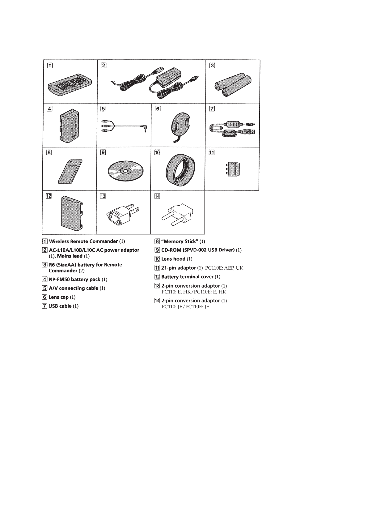
• SUPPLIED ACCESSORIES
Check that the following accessories are supplied with your camcorder.
Abbreviation
HK: Hong Kong model
JE: Tourist model
— 3 —

TABLE OF CONTENTS
SERVICE NOTE
1. POWER SUPPLY DURING REPAIRS ····························· 7
2. HOW TO OPEN THE FLASH WHEN THE FLASH
DOESN’T OPEN ······························································· 7
3. TO TAKE OUT A CASSETTE WHEN NOT EJECT
(FORCE EJECT) ································································ 7
4. DISCHARGING OF THE FLASHLIGHT POWER
SUPPLY CAPACITOR ······················································ 8
4-1. PREPARING THE SHORT JIG·········································8
4-2. DISCHARGING THE CAPA CIT OR································· 8
SELF-DIAGNOSIS FUNCTION
1. SELF-DIAGNOSIS FUNCTION······································· 9
2. SELF-DIAGNOSIS DISPLAY ·········································· 9
3. SERVICE MODE DISPLAY ·············································9
3-1. Display Method ·································································· 9
3-2. Switching of Backup No. ···················································9
3-3. End of Display····································································9
4. SELF-DIAGNOSIS CODE TABLE································· 10
1. GENERAL
Checking supplied accessories ·················································· 1-1
Quick Start Guide ······································································1-1
Getting started
Using this manual ··································································1-1
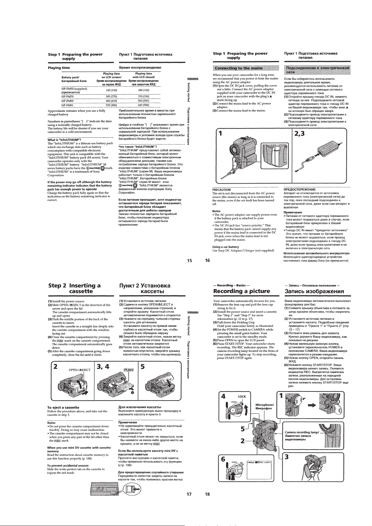
Step 1 Preparing the power supply ········································1-2
Installing the battery pack···················································· 1-2
Charging the battery pack ····················································1-2
Connecting to the mains ······················································1-3
Step 2 Inserting a cassette······················································1-3
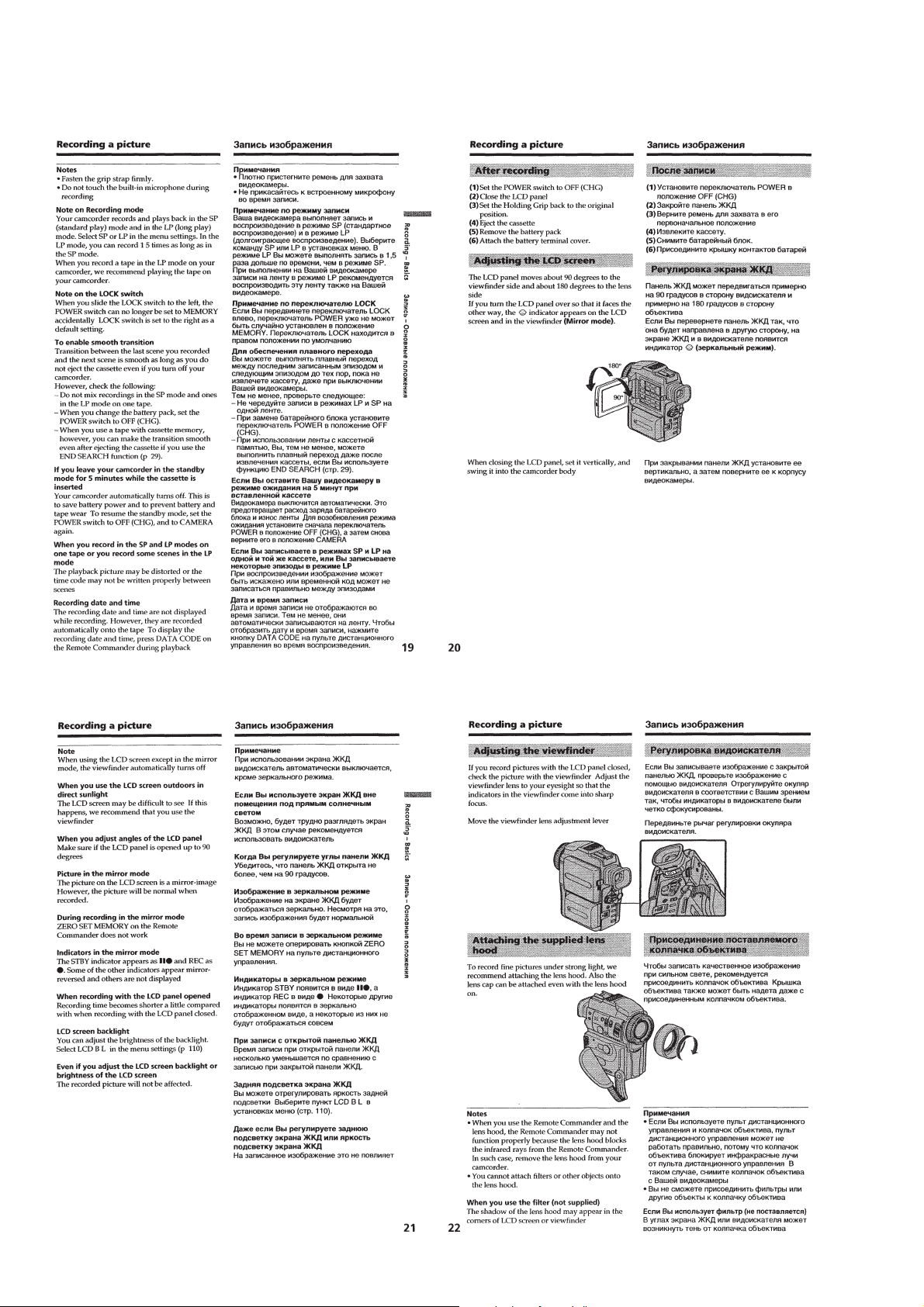
Recording –Basics
Recording a picture································································1-3
Shooting backlit subjects –BACK LIGHT ··························1-5
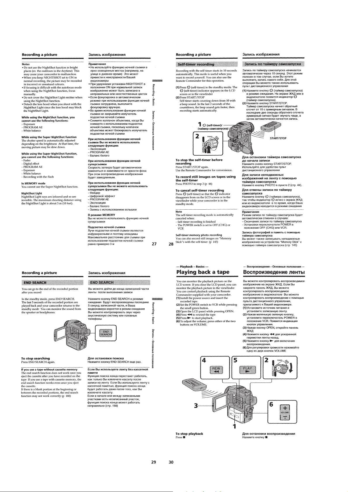
Shooting in the dark –NightShot/Super NightShot ·············1-5
Self-timer recording·····························································1-6
END SEARCH ····································································1-6
Playback –Basics
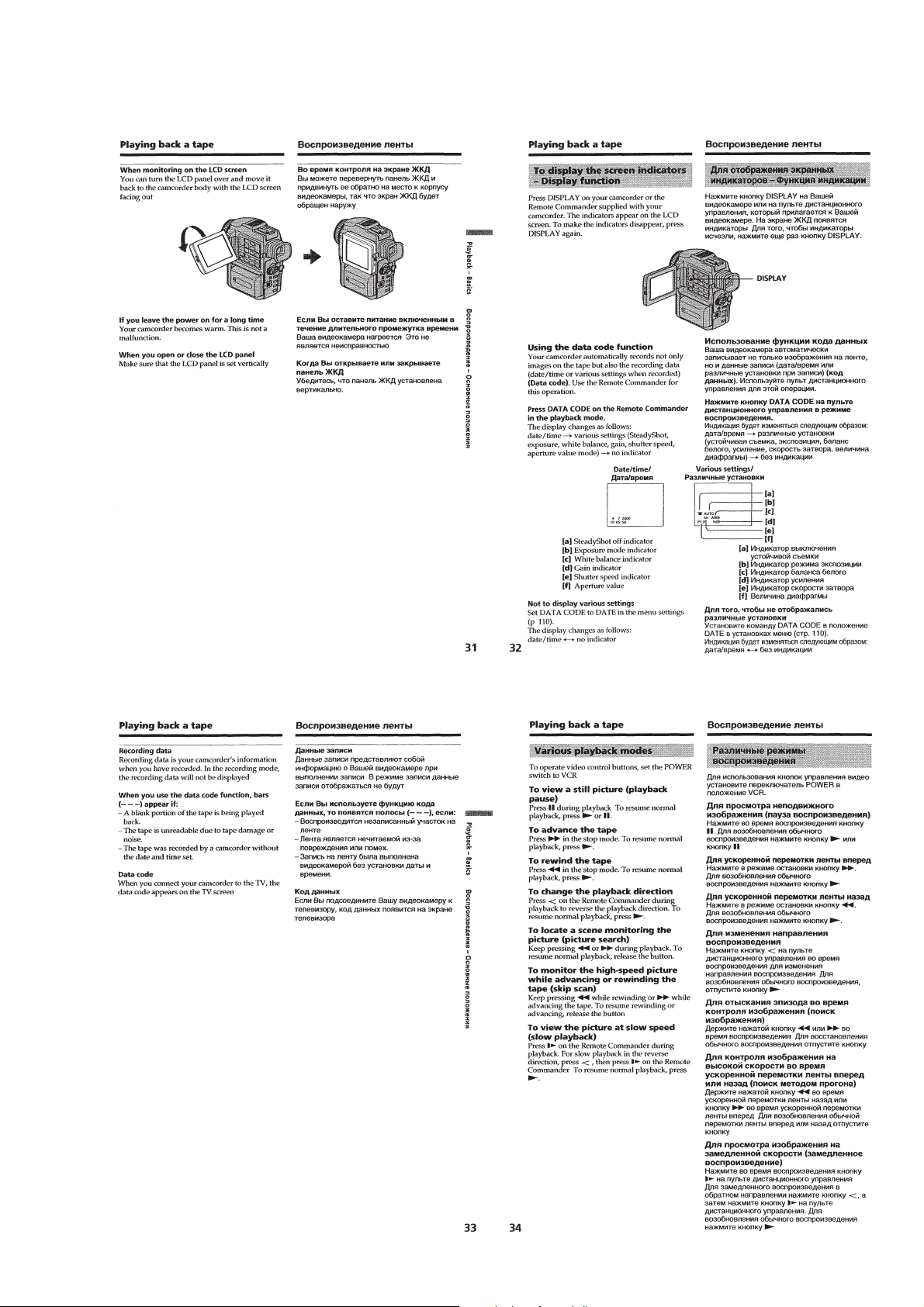
Playing back a tape ································································1-6
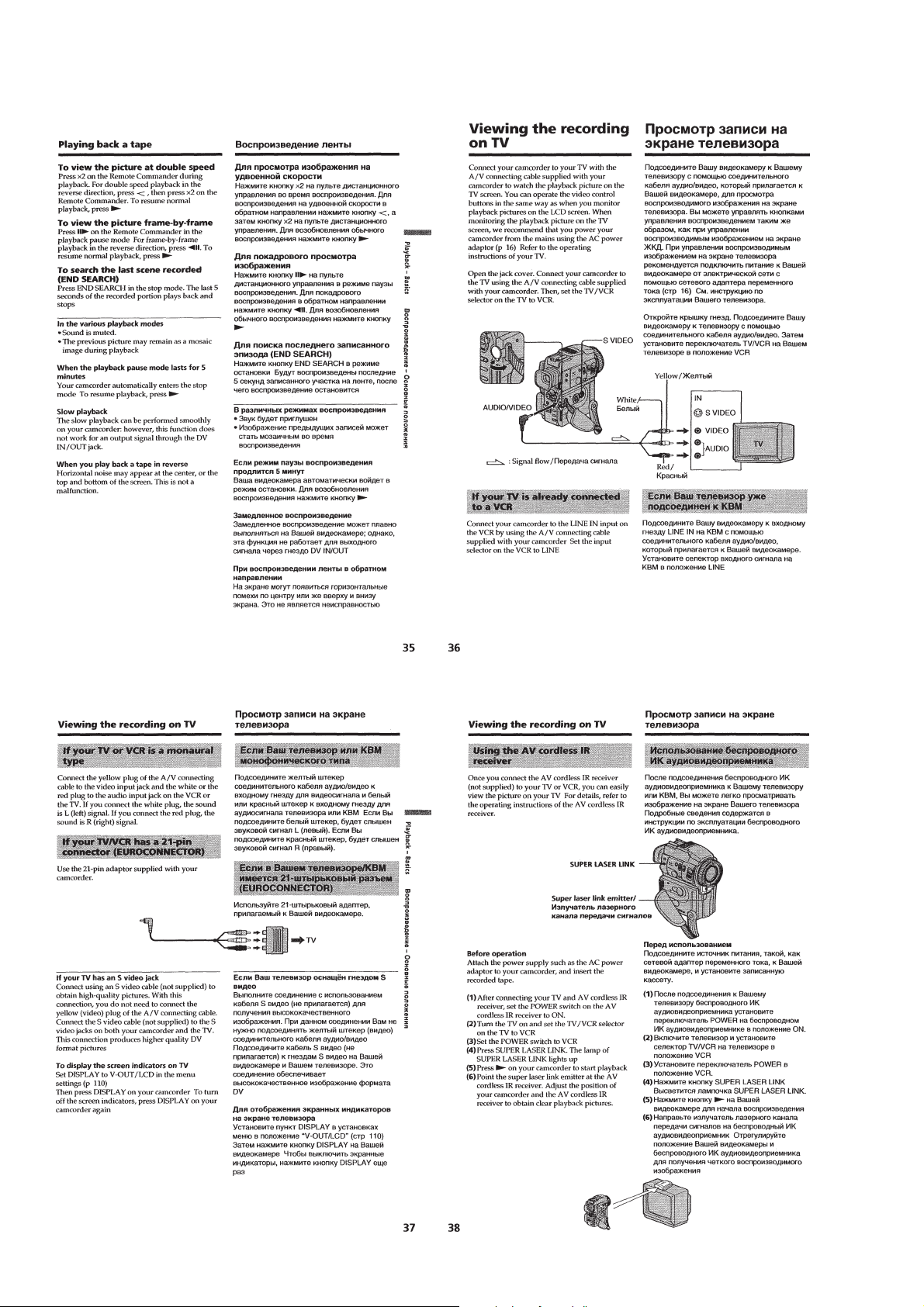
Viewing the recording on TV ················································1-8
Advanced Recording Operations
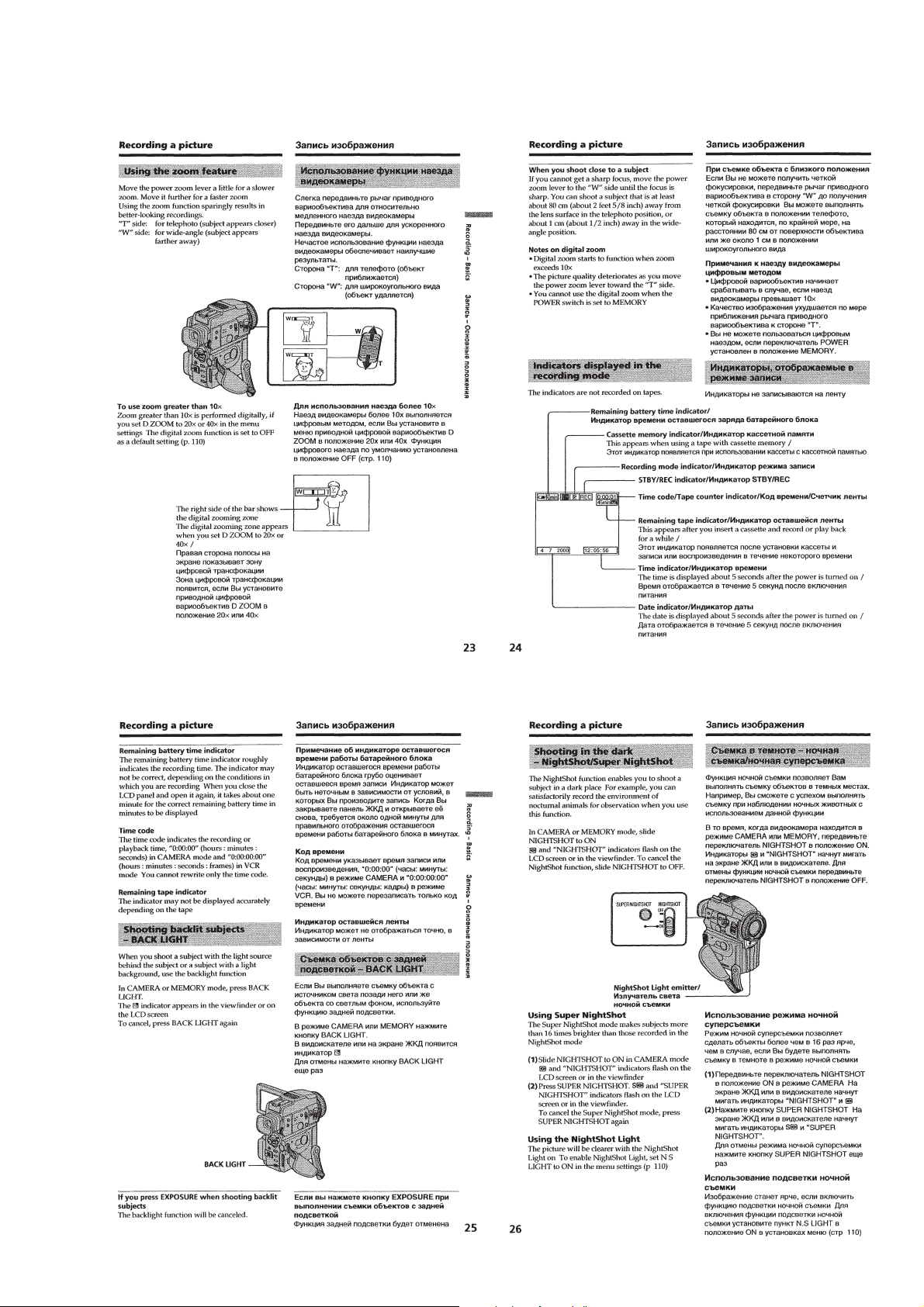
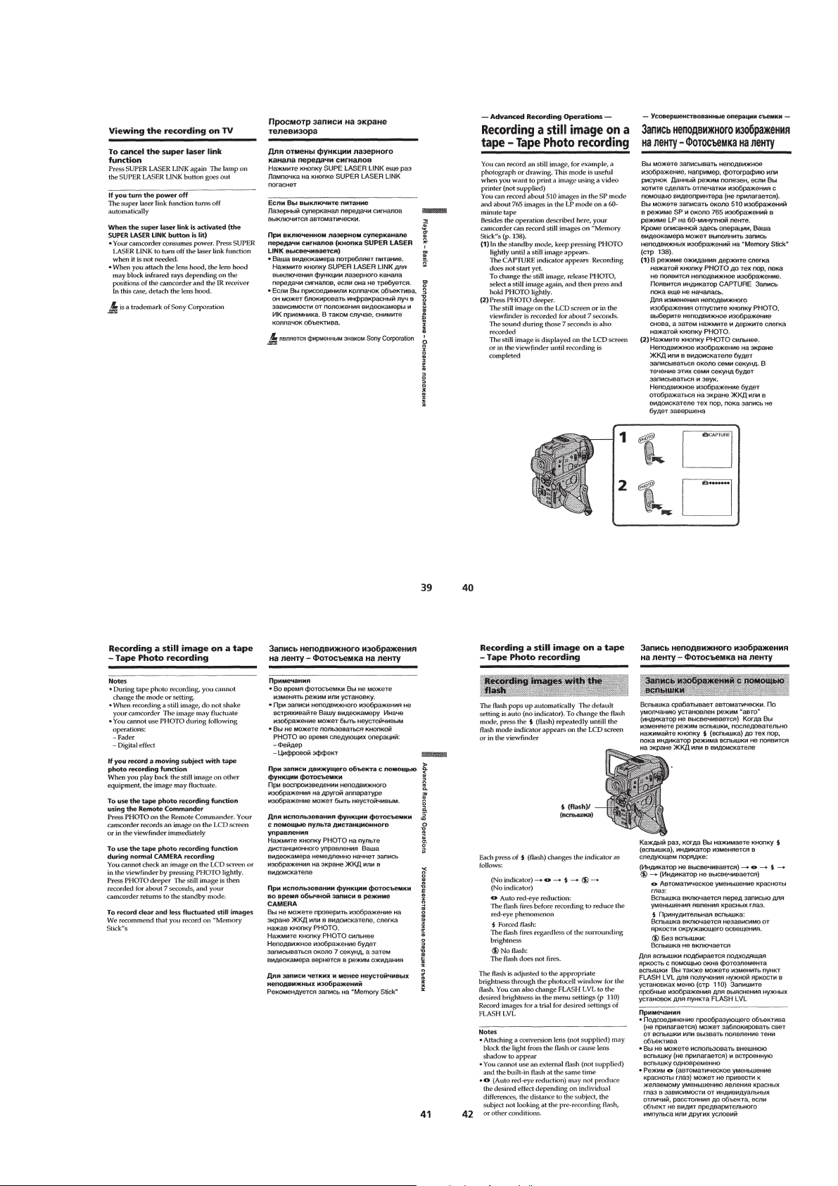
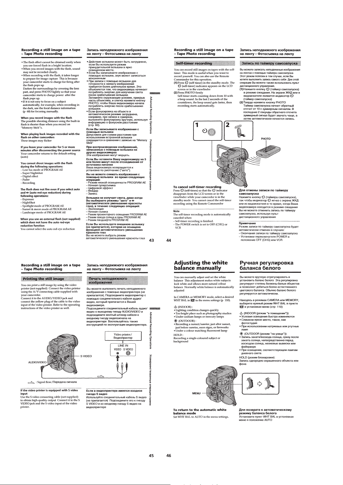
Recording a still image on a tape –Tape Photo recording ·····1-9
Adjusting the white balance manually································· 1-10
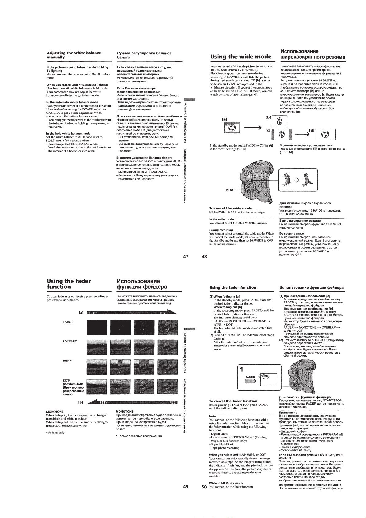
Using the wide mode ···························································1-11
Using the fader function ······················································1-11
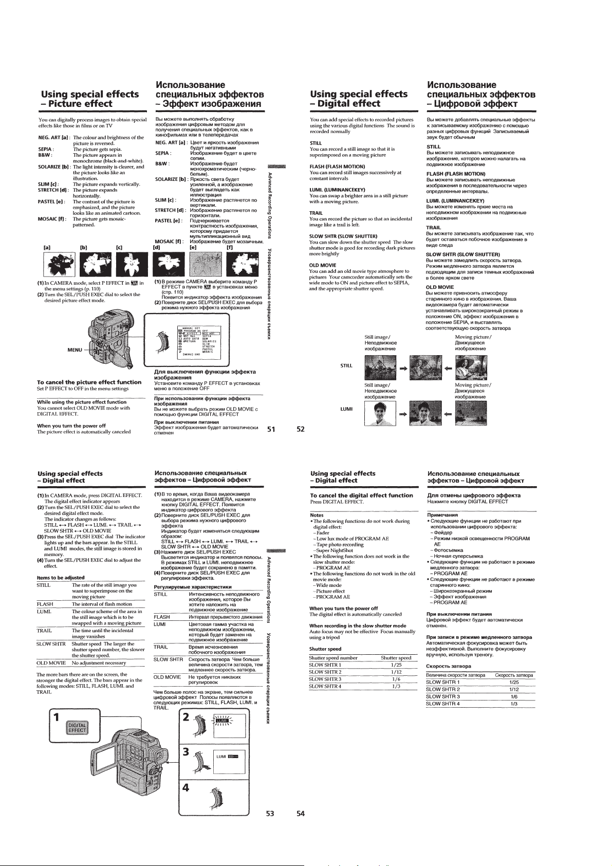
Using special effects –Picture effect····································1-12
Using special effects –Digital effect····································1-12
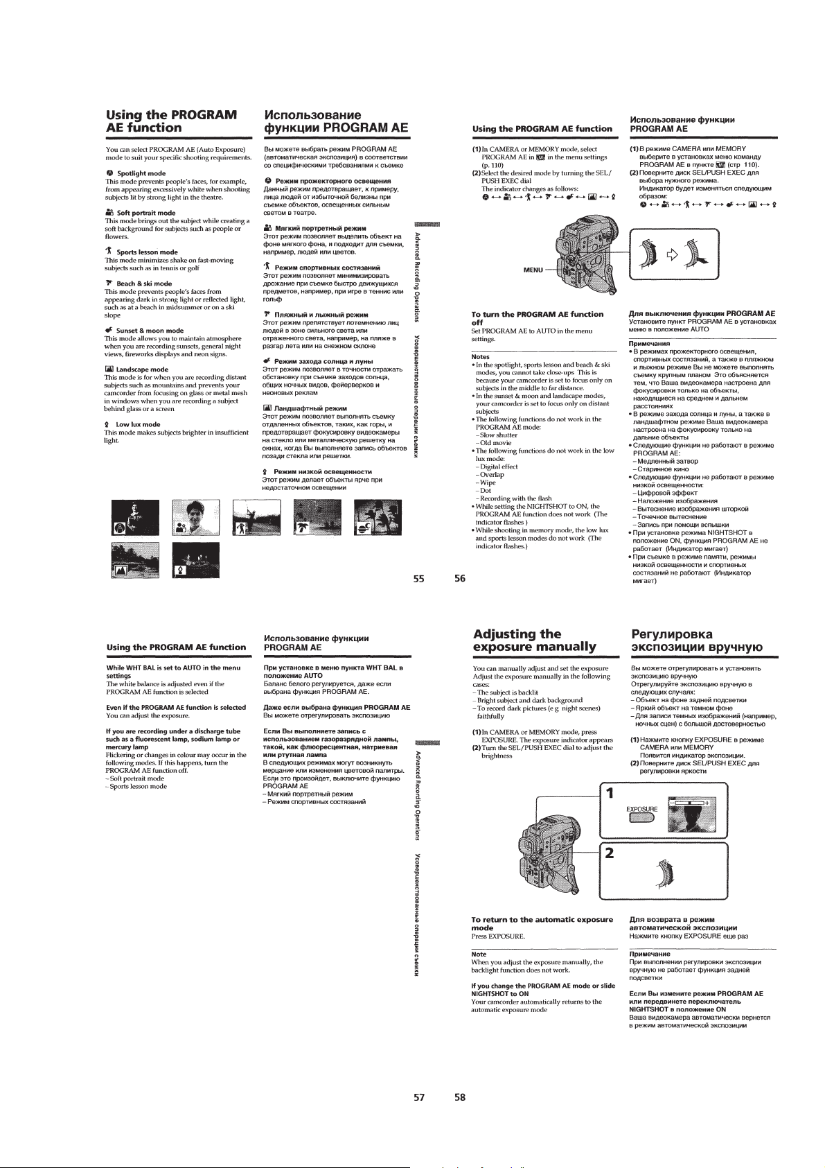
Using the PROGRAM AE function ·····································1-13
Adjusting the exposure manually ········································1-13
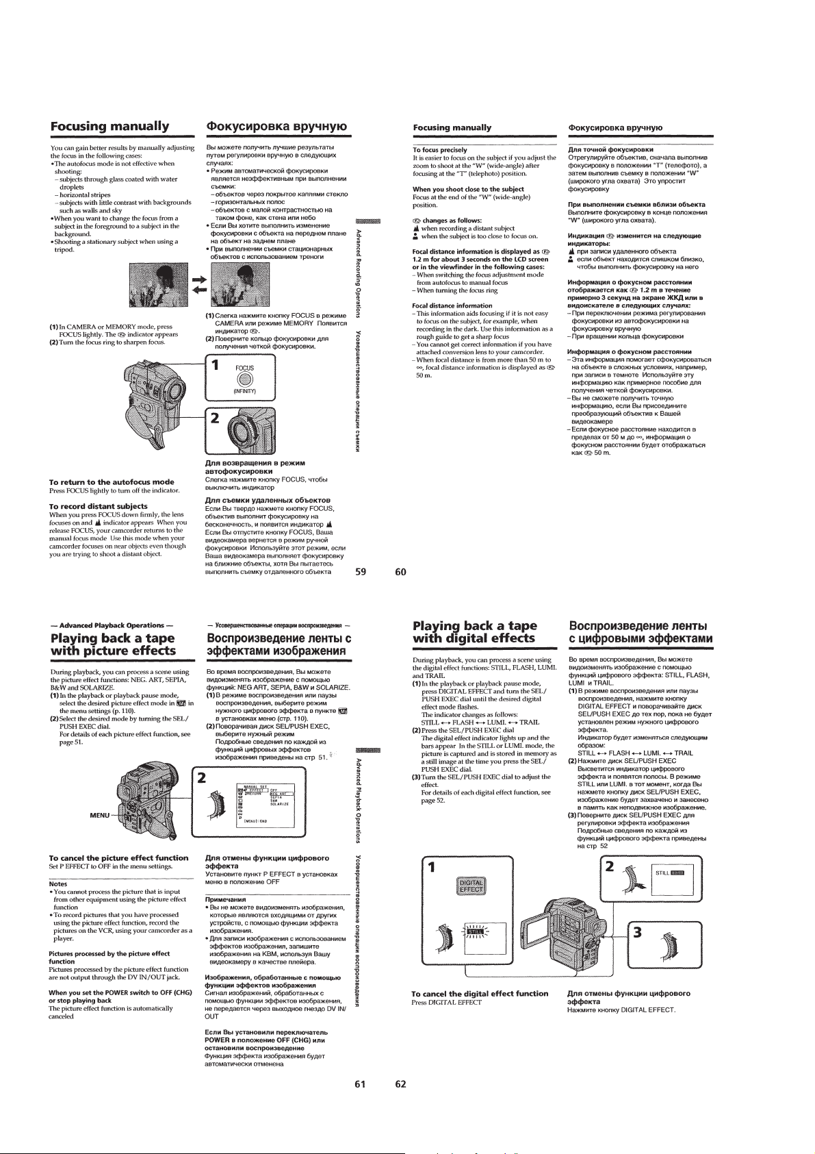
Focusing manually·······························································1-14
Advanced Playback Operations
Playing back a tape with picture effects ······························1-14
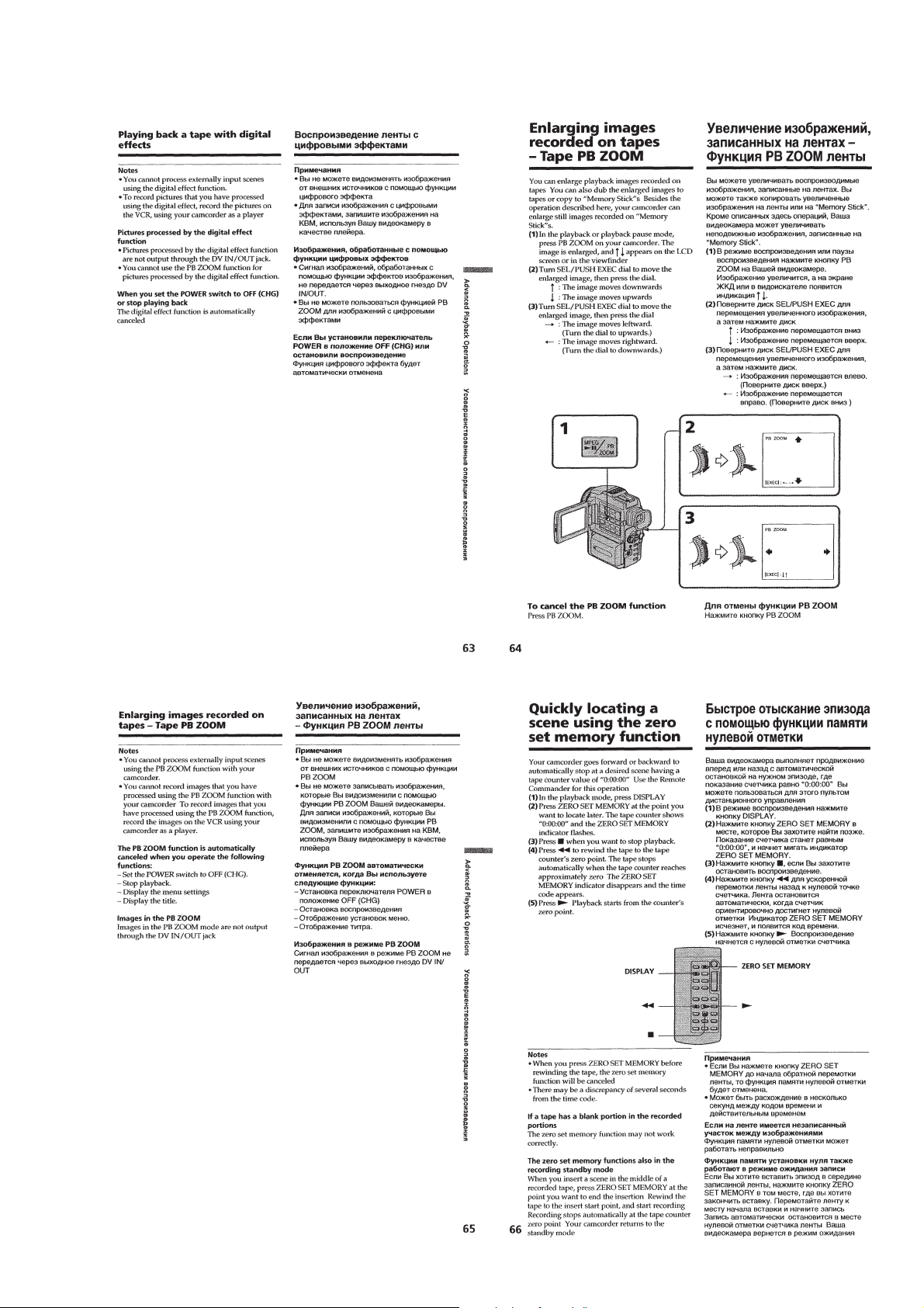
Playing back a tape with digital effects ·······························1-14
Enlarging images recorded on –Tape PB ZOOM ··············· 1-15
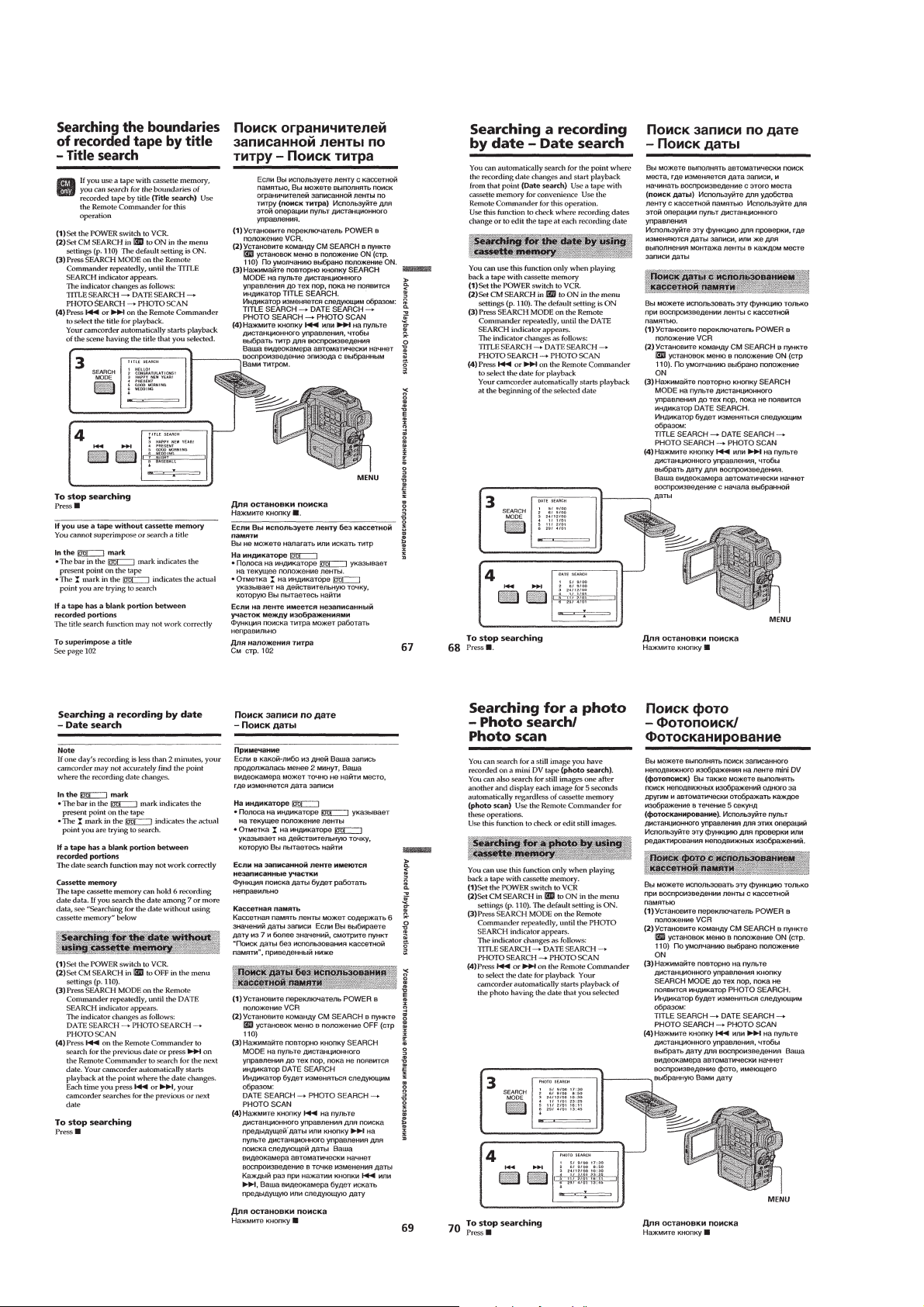
Quickly locating a scene using the zero set memory function ··
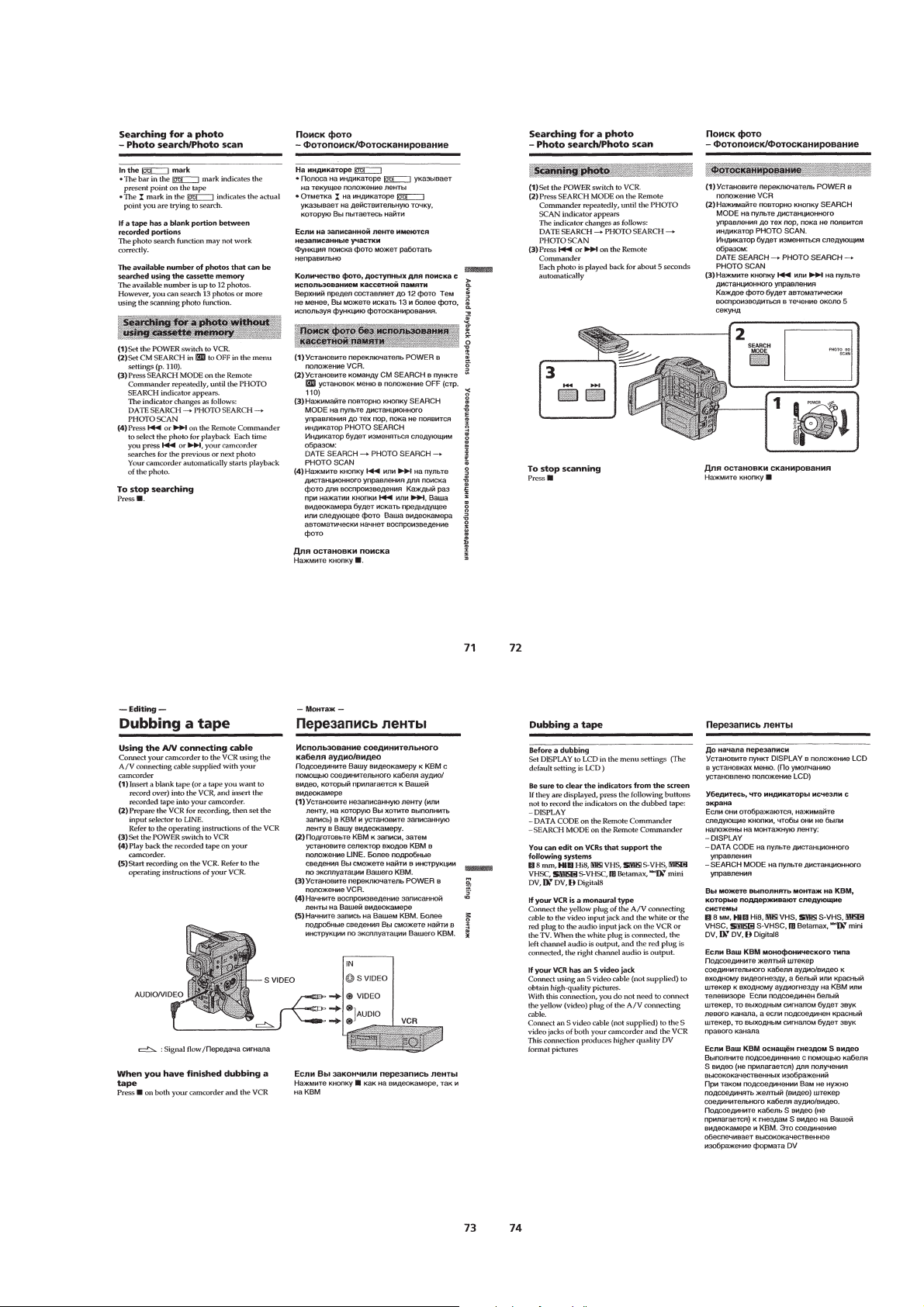
Searching the boundaries of recorded tape by title
–Title search······································································1-16
Searching a recording by date –Date search························1-16
Searching for a photo –Photo search/Photo scan················· 1-16
Editing
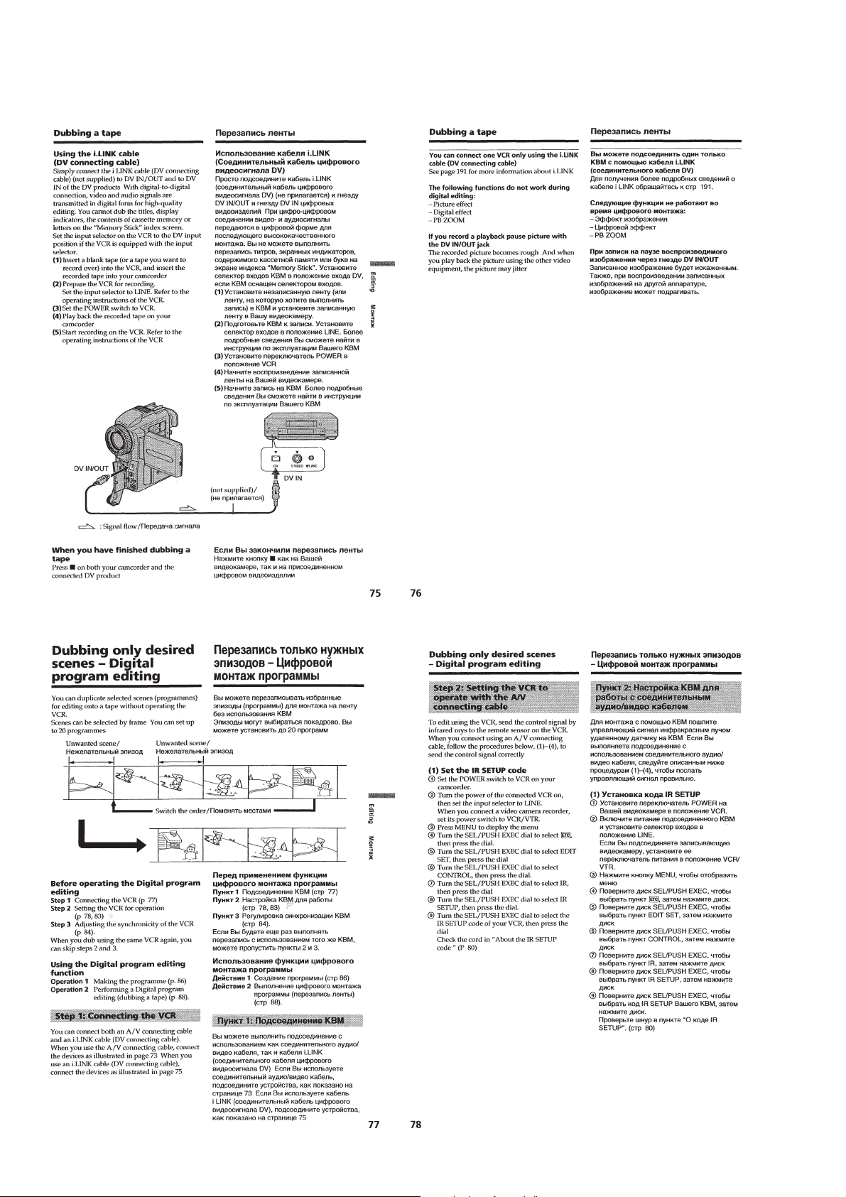
Dubbing a tape ·····································································1-17
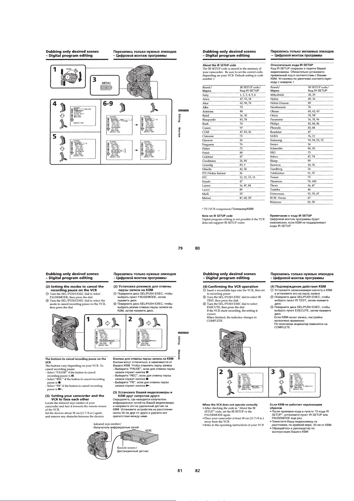
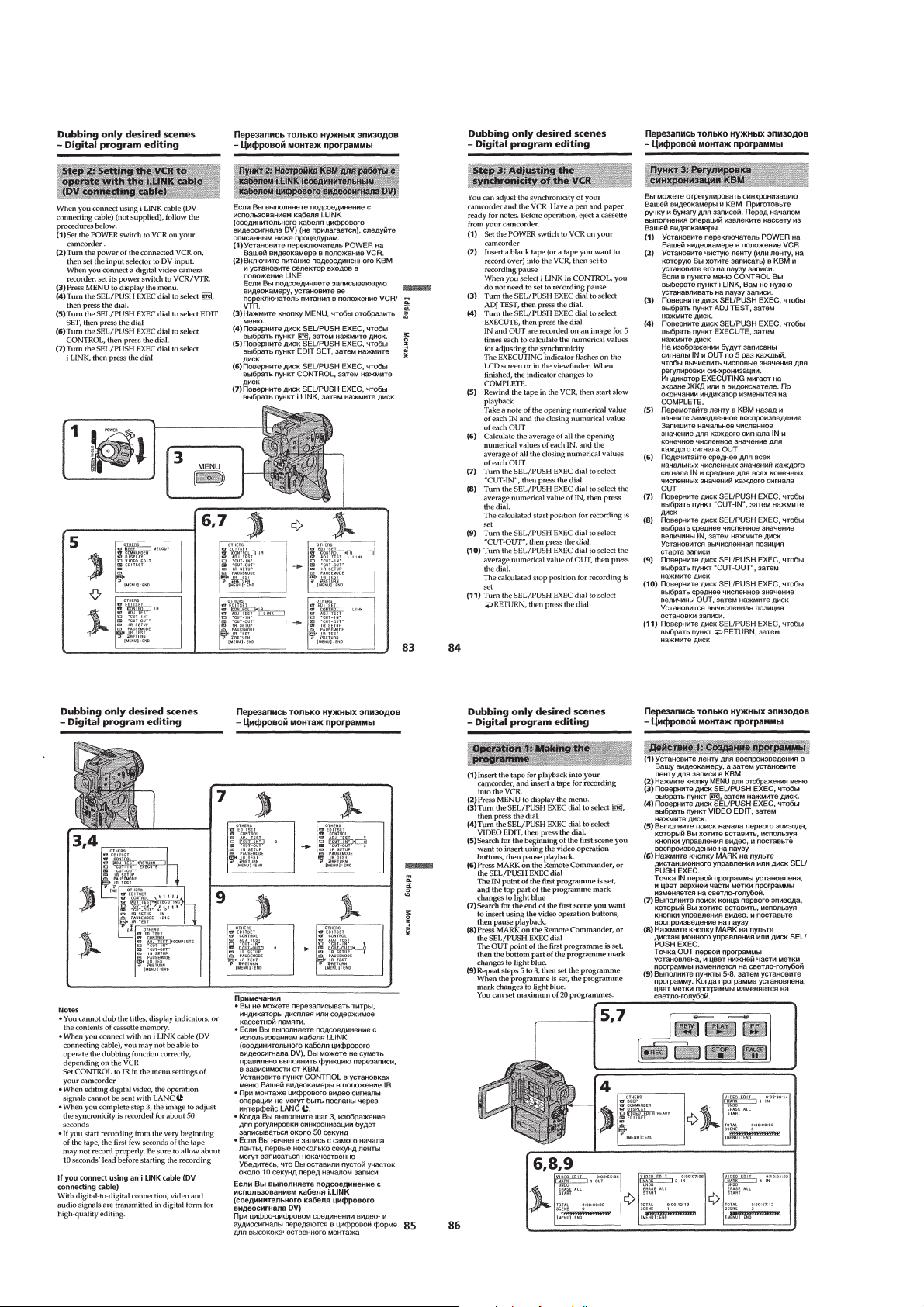
Dubbing only desired scenes –Digital program editing ······1-18
Using with analog video unit and personal computer
–Signal convert function···················································1-21
Recording video or TV programmes ···································1-22
Inserting a scene from a VCR –Insert editing······················1-23
Audio dubbing ·····································································1-23
Superimposing a title ···························································1-24
1-15
Making your own titles ························································1-25
Labeling a cassette ·······························································1-26
Customizing Y our Camcorder
Changing the menu settings·················································1-26
Resetting the date and time··················································1-28
“Memory Stick” Operations
Using a “Memory Stick” –introduction ·······························1-29
Recording still images on “Memory Stick”s
–Memory photo recording ················································1-32
Recording an image from a mini DV tape as a still image ··1-34
Recoding moving pictures on “Memory Stick”s
–MPEG movie recoding ··················································· 1-35
Recoding a picture from a mini DV tape as a moving picture ··
Superimposing a still image in a “Memory Stick” on a
moving picture –MEMORY MIX ·······································1-36
Copying still images from a mini DV tape –Photo save ······1-37
Viewing a still image –Memory photo playback ·················1-37
Viewing a moving picture –MPEG movie playback ···········1-38
Viewing images using a personal computer ························1-39
Copying the images recorded on “Memory Stick”s to mini
DV tapes ·············································································· 1-41
Enlarging still images recorded on “Memory Stick”s
–Memory PB ZOOM ························································1-41
Playing back images in a continuous loop
Preventing accidental erasure –Image protection ················1-42
Deleting images ··································································· 1-43
Writing a print mark –PRINT MARK·································1-44
Additional Information
Usable cassettes ··································································· 1-44
About i.LINK·······································································1-45
Troubleshooting ···································································1-45
Self-diagnosis display ··························································1-47
Warning indicators and messages ········································1-47
Using your camcorder abroad··············································1-48
Maintenance information and precautions···························1-48
Quick Reference
Identifying the parts and controls ········································ 1-49
Quick Function Guide ·························································1-52
–SLIDE SHOW ·
1-35
1-42
2. DISASSEMBLY
2-1. PD-134 BOARD, INVER TER TRANSFORMER UNIT··· 2-2
2-2. CABINET (L) BLOCK ASSEMBLY ·····························2-3
2-3. EVF BLOCK ASSEMBLY ············································· 2-4
2-4. VTR OVERALL SECTION,
CABINET (R) BLOCK ASSEMBLY ·····························2-5
2-5. FLASH UNIT (MC), FLASH UNIT (ST) ······················2-5
2-6. FJ-027 BOARD ·······························································2-6
2-7. CD-285 BOARD, LENS DEVICE LSV-690B ···············2-6
2-8. AI-021, VC-253 BOARDS, MECHANISM DECK ·······2-7
2-9. CONTROL SWITCH BLOCK (PS30550),
CONTROL SWITCH BLOCK (FK30550)·····················2-8
2-10. LCD HINGE ASSEMBLY··············································2-9
2-11. CIRCUIT BOARDS LOCATION·································2-10
2-12. FLEXIBLE BOARDS LOCATION ······························2-11
3. BLOCK DIAGRAMS
3-1. OVERALL BLOCK DIAGRAM (1/3) ···························3-1
3-2. OVERALL BLOCK DIAGRAM (2/3) ···························3-3
3-3. OVERALL BLOCK DIAGRAM (3/3) ···························3-5
3-4. POWER BLOCK DIAGRAM (1/2)································3-7
3-5. POWER BLOCK DIAGRAM (2/2)································3-9
4. PRINTED WIRING BOARDS AND
SCHEMATIC DIAGRAMS
4-1. FRAME SCHEMATIC DIAGRAM (1/2) ·······················4-1
FRAME SCHEMATIC DIAGRAM (2/2) ·······················4-3
— 4 —

4-2. PRINTED WIRING BOARDS AND
SCHEMATIC DIAGRAMS ············································ 4-5
• CD-285 (CCD IMAGER)
PRINTED WIRING BOARD ·························4-7
• CD-285 (CCD IMAGER),
CONTROL SWITCH BLOCK (MF30550)
SCHEMATIC DIAGRAMS····························4-9
Shematic diagram and printed wiring board of the
VC-253 board are not shown.
Pages from 4-11 to 4-52 are not shown.
• AI-021 (LINE IN/OUT)(1/3)
SCHEMATIC DIAGRAM ····························4-53
• AI-021 (AUDIO IN/OUT, DAC/ADC)(2/3)
SCHEMATIC DIAGRAM ····························4-55
• AI-021 (MIC AMP)(3/3), MIC (MIC UNIT)
SCHEMATIC DIAGRAMS··························4-57
• AI-021 (AUDIO PROCESSOR, LINE IN/OUT)
PRINTED WIRING BOARD ·······················4-59
• CONTROL SWITCH BLOCK (FK30550)
SCHEMATIC DIAGRAM ····························4-63
• CONTROL SWITCH BLOCK (FK30550)
PRINTED WIRING BOARD ·······················4-65
• CONTROL SWITCH BLOCK (ME30550)
SCHEMATIC DIAGRAM ····························4-66
• CONTROL SWITCH BLOCK (PS30550),
FP-256 (SIRCS, IR)
SCHEMATIC DIAGRAMS··························4-67
• FLASH UNIT (30550MC/30550ST)
SCHEMATIC DIAGRAMS··························4-69
• PD-134 (RGB DRIVE, TIMING GENE.)
PRINTED WIRING BOARD ·······················4-71
• PD-134 (RGB DRIVE, TIMING GENE.)
SCHEMATIC DIAGRAM ····························4-73
• VF-147 (LCD DRIVE, BACK-LIGHT)
PRINTED WIRING BOARD ·······················4-75
• VF-147 (LCD DRIVE, BACK-LIGHT)
SCHEMATIC DIAGRAM ····························4-77
• FJ-027 (DC IN)
PRINTED WIRING BOARD ·······················4-79
• FJ-027 (DC IN), FP-251 (PANEL DETECT)
SCHEMATIC DIAGRAMS··························4-83
• FP-100 (MODE SWITCH), FP-228 (DEW SENSOR),
FP-102 (TAPE TOP/END SENSOR, S/T REEL)
FLEXIBLE BOARDS··································4-85
4-3. WAVEFORMS ······························································ 4-88
4-4. MOUNTED PARTS LOCATION ·································4-92
5. ADJUSTMENTS
1. Before starting adjustment···············································5-1
1-1. Adjusting items when replacing main parts and boards. ··· 5-2
5-1. CAMERA SECTION ADJUSTMENT···························5-4
1-1. PREPARATIONS BEFORE ADJUSTMENT
(CAMERA SECTION) ···················································5-4
1-1-1.List of Service Tools ························································5-4
1-1-2.Preparations ·····································································5-5
1-1-3.Precaution ········································································5-7
1. Setting the Switch···························································· 5-7
2. Order of Adjustments ······················································5-7
3. Subjects ···········································································5-7
1-2. INITIALIZATION OF B, C, D, E, F, 7, 8 PAGE DATA ···5-8
1-2-1.INITIALIZATION OF C, D, 8 PA GE DATA ··················5-8
1. Initializing the C, D, 8 Page Data····································5-8
2. Modification of C, D, 8 Page Data ··································5-8
3. C Page Table ····································································5-8
4. D Page Table ··································································5-10
5. 8 Page Table···································································5-10
1-2-2.INITIALIZATION OF B PAGE DATA·························5-11
1. Initializing the B Page Data···········································5-11
2. Modification of B Page Data·········································5-11
3. B Page Table ··································································5-11
1-2-3.INITIALIZATION OF E, F, 7 PAGE DATA ·················5-12
1. Initializing the E, F, 7 Page Data ···································5-12
2. Modification of E, F, 7 Page Data ·································5-12
3. F Page Table ··································································5-12
4. E Page Table ··································································5-13
5. 7 Page Table···································································5-14
1-3. CAMERA SYSTEM ADJUSTMENTS························ 5-15
1. 54MHz/66MHz Origin Oscillation Adjustment
(CD-285 board) ·····························································5-15
2. Zoom Key Center Adjustment ·······································5-15
3. HALL Adjustment ·························································5-16
4. MR Adjustment ·····························································5-17
5. Flange Back Adjustment (Using Minipattern Box)·······5-18
6. Flange Back Adjustment
(Using Flange Back Adjustment Chart and Subject
More Than 500m Away) ················································5-19
6-1. Flange Back Adjustment (1)··········································5-19
6-2. Flange Back Adjustment (2)··········································5-19
7. Flange Back Check························································ 5-20
8. Picture Frame Setting ···················································· 5-20
9. Color Reproduction Adjustment····································5-21
10. MAX GAIN Adjustment ···············································5-22
11. Auto White Balance & LV Standard Data Input ···········5-22
12. Auto White Balance Adjustment ···································5-23
13. White Balance Check ····················································5-24
14. Mechanical Shutter Data Input······································5-25
15. Angular Velocity Sensor Sensitivity Adjustment ··········5-25
16. Strobe Light Level Adjustment ····································· 5-26
17. Strobe Light Level Adjustment for Movie Mode ··········5-26
18. Strobe White Balance Adjustment & Check ·················5-27
1-4. COLOR ELECTRONIC VIEWFINDER SYSTEM
ADJUSTMENT·····························································5-28
1. VCO Adjustment (VF-147 board)································· 5-28
2. Bright Adjustment (VF-147 board) ·······························5-29
3. Contrast Adjustment (VF-147 board)····························5-29
4. White Balance Adjustment (VF-147 board)··················5-30
1-5. LCD SYSTEM ADJUSTMENT ···································5-31
1. VCO Adjustment (PD-134 board)································· 5-31
2. Bright Adjustment (PD-134 board) ·······························5-32
3. Black Limit Adjustment (PD-134 board) ······················5-32
4. Contrast Adjustment (PD-134 board)····························5-33
5. Center Level Adjustment (PD-134 board) ·····················5-33
6. V-COM Adjustment (PD-134 board) ····························5-34
7. White Balance Adjustment (PD-134 board)··················5-34
5-2. MECHANISM SECTION ADJUSTMENT··················5-35
2-1. HOW TO ENTER RECORD MODE WITHOUT
CASSETTE ···································································5-35
2-2. HOW TO ENTER PLAYBACK MODE WITHOUT
CASSETTE ···································································5-35
2-3. TAPE PATH ADJUSTMENT········································5-35
1. Preparation for Adjustment ···········································5-35
2. Procedure after operations·············································5-35
5-3. VIDEO SECTION ADJUSTMENTS ···························5-36
3-1. PREPARATIONS BEFORE ADJUSTMENTS ············ 5-36
3-1-1.Equipment Required ······················································5-36
3-1-2. Precautions on Adjusting ··············································5-37
3-1-3.Adjusting Connectors ····················································5-38
3-1-4.Connecting the Equipment ············································5-38
3-1-5.Alignment Tapes····························································5-39
3-1-6.Input/Output Level and Impedance ·······························5-39
3-2. SYSTEM CONTROL SYSTEM ADJUSTMENT ········5-40
1. Initialization of B, C, D, E, F, 7, 8 Page Data ···············5-40
— 5 —

2. Serial No. Input ·····························································5-40
2-1. Company ID Input·························································5-40
2-2. Serial No. Input ·····························································5-40
3. Battery End Check (VC-253 board) ······························5-42
3-3. SERVO AND RF SYSTEM ADJUSTMENT ···············5-43
1. Cap FG Duty Adjustment (VC-253 Board)···················5-43
2. PLL f0 & LPF f0 Adjustment (VC-253 Board)··············5-43
3. Switching Position Adjustment (VC-253 Board)··········5-44
4. AGC Center Level and APC & AEQ Adjustment ·········5-44
4-1. Preparations before adjustments···································· 5-44
4-2. AGC Center Level Adjustment (VC-253 Board) ··········5-44
4-3. APC & AEQ Adjustment (VC-253 Board) ···················5-45
4-4. Processing after Completing Adjustments ····················5-45
5. PLL f0 & LPF f0 Final Adjustment (VC-253 Board)·····5-46
3-4. VIDEO SYSTEM ADJUSTMENTS·····························5-47
3-4-1.Base Band Block Adjustments ······································5-47
1. Chroma BPF f0 Adjustment (AI-021 Board)·················5-47
2. S VIDEO OUT Y Level Adjustment (VC-253 Board) ··5-47
3. S VIDEO OUT Chroma Level Adjustment
(VC-253 Board)·····························································5-48
4.
VIDEO OUT Y, Chroma Le vel Check (VC-253 Board) ··
3-5. IR TRANSMITTER ADJUSTMENTS·························5-49
1.
IR Video Carrier Frequency Adjustment (VC-253 board) ··
2. IR Video Deviation Adjustment (VC-253 board)·········· 5-49
3. IR Audio Deviation Adjustment (VC-253 board) ·········5-50
3-6. AUDIO SYSTEM ADJUSTMENTS ····························5-51
1. Playback Level Check ···················································5-52
2. Overall Level Characteristics Check ·····························5-52
3. Overall Distortion Check···············································5-52
4. Overall Noise Level Check············································ 5-52
5. Overall Separation Check·············································· 5-52
5-4. SERVICE MODE ·························································· 5-53
4-1. ADJUSTMENT REMOTE COMMANDER ················5-53
1. Using the adjustment remote commander ·····················5-53
2. Precautions upon using the adjustment remote
commander ····································································5-53
4-2. DATA PROCESS···························································5-54
4-3. SERVICE MODE ·························································· 5-55
1. Setting the Test Mode ····················································5-55
2. Emergence Memory Address ········································5-55
2-1. EMG Code (Emergency Code) ·····································5-55
2-2. MSW Code ····································································5-56
3. Bit value discrimination ················································5-57
4. Switch check (1) ····························································5-57
5. Switch check (2) ····························································5-58
6. Record of Use check······················································5-58
7. Record of Self-diagnosis check ·····································5-59
5-48
5-49
6. REPAIR PARTS LIST
6-1. EXPLODED VIEWS ······················································6-1
6-1-1.OVERALL SECTION·····················································6-1
6-1-2.CABINET (L) SECTION················································6-2
6-1-3.EVF SECTION································································6-3
6-1-4.VTR OVERALL SECTION············································6-4
6-1-5.CABINET (R) SECTION-1 ············································6-5
6-1-6.CABINET (R) SECTION-2 ············································6-6
6-1-7.CASSETTE COMP ARTMENT AND DRUM BLOCK
ASSEMBLY ····································································6-7
6-1-8.LS CHASSIS BLOCK ASSEMBLY······························· 6-8
6-1-9.MECHANISM CHASSIS BLOCK ASSEMBLY ···········6-9
6-2. ELECTRICAL PARTS LIST ········································6-10
Parts list of the VC-253 board are not shown.
Pages from 6-16 to 6-26 are not shown.
* Color reproduction frame is shown on page 217.
— 6 —
SERVICE NOTE
1. POWER SUPPLY DURING REPAIRS
In this unit, about 10 seconds after power is supplied to the battery terminal using the regulated power supply (8.4V), the po wer is shut of f so
that the unit cannot operate.
This following two methods are available to prevent this. Take note of which to use during repairs.
Method 1.
Use the AC power adaptor (AC-L10, AC-VQ800 etc.).
Method 2.
Connect the servicing remote commander RM-95 (J-6082-053-B) to the LANC jack, and set the commander switch to the “ADJ” side.
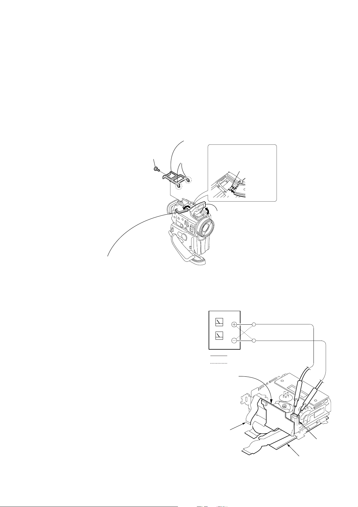
2. HOW TO OPEN THE FLASH WHEN THE FLASH DOESN’T OPEN
3
Cabinet (upper)
1
Screw
(M1.7
lock ace, p2
×
4),
2
Two claws
5
Push the lock plate in the
direction of the arrow
to open the flash unit.
Lock plate
B
B
4
Move the microphone block
in the direction of the arrow
A
A
.
6
Open the flash unit.
3. TO TAKE OUT A CASSETTE WHEN NOT EJECT (FORCE EJECT)
1 Refer to 2-2. to remove the jack ornamental plate.
2 Refer to 2-2. to remove the upper cabinet .
3 Refer to “2. HOW TO OPEN THE FLASH WHEN THE FLASH
DOESN’T OPEN” to open the flash.
4 Refer to 2-2. to remove the cabinet (L) assembly.
5 Refer to 2-2. to remove the microphone unit.
6 Refer to 2-3. to remove the EVF block.
7 Refer to 2-4. to remove the cabinet (R) assembly.
8 Refer to 2-7. to remove the IR window.
9 Refer to 2-7. to remove the MF ring.
0 Refer to 2-7. to remove the lens block.
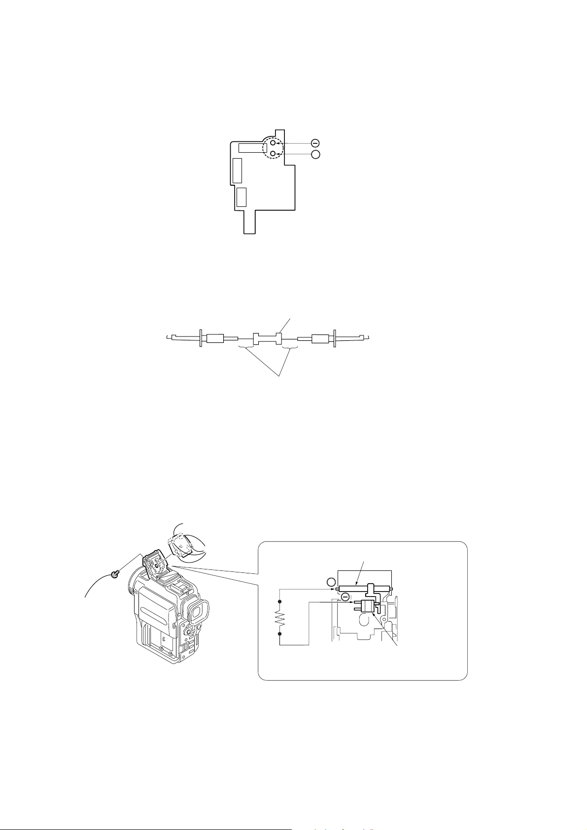
qa Disconnect CN256 (27P) of VC-253 board.
qs Supply +4.5V from the DC power supply to the loading motor
and unload with a pressing the cassette compartment.
DC power supply
(+4.5Vdc)
: Unloading
: Loading
AI-021 board
Disconnect from CN256
— 7 —
AI-021 board
Loading motor
VC-253 board
4. DISCHARGING OF THE FLASHLIGHT POWER SUPPLY CAPACITOR
The capacitor (C2010) of the flash unit is charged up to the maximum 300V potential.
There is a danger of electric shock by this high voltage when the capacitor is handled by hand. The electric shock is caused by the charged
voltage which is kept without discharging when the main power of the unit is simply turned off. Therefore, the remaining voltage must be
discharged as described below.
C2010
FLASH UNIT
(30550MC)
4-1. PREPARING THE SHORT JIG
+
To preparing the short jig. a small clip is attached to each end of a resistor of 1kΩ/1W (1-215-869-11)
Wrap insulating tape fully around the reads of the resistor to prevent electric shock.
1 kΩ/1 W
Wrap insulating tape.
4-2. DISCHARGING THE CAP ACITOR
* Use either one of the following two procedure to discharge the capacitor.
< DISCHARGING THE CAPACITOR-1 >
1 Remove the power supply (Battery or AC power adaptor).
2 Refer to “2. HOW TO OPEN THE FLASH WHEN THE FLASH DOESN’T OPEN” to open the flash. (Page 7)
3 Remove the upper ST cabinet.
4 Short circuit between the anode 3 of the xenon lamp and the GND # terminal of the trigger transformer (L2010) with the short jig
about 10 seconds.
3
ST cabinet (upper)
2
1
Screw,
tapping
Remove the
four claws.
Short jig
Xenon tube
+
Trigger transformer
FLASH UNIT
< DISCHARGING THE CAPACITOR-2 >
1 Remove the power supply (Battery or AC power adaptor).
2 Short circuit between 3 and # terminal of the capacitor (C2010) with the short jig about 10 seconds.
— 8 —
SELF-DIAGNOSIS FUNCTION
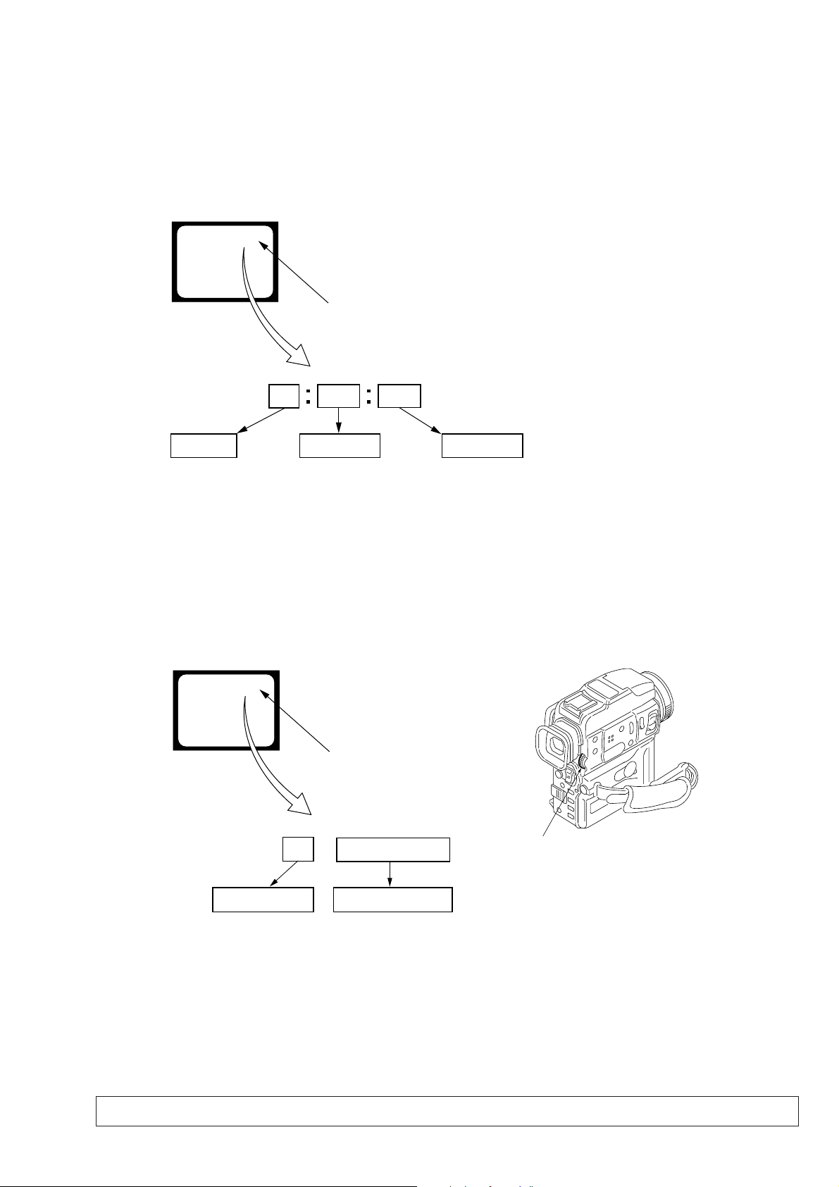
1. SELF-DIAGNOSIS FUNCTION
When problems occur while the unit is operating, the self-diagnosis
function starts working, and displays on the viewfinder or LCD
screen what to do. This function consists of two display; selfdiagnosis display and service mode display .
Details of the self-diagnosis functions are provided in the Instruction
manual.
Viewfinder or LCD screen
C : 3 1 : 1 1
Repaired by:
C : Corrected by customer
H : Corrected by dealer
E : Corrected by service
engineer
Blinks at 3.2Hz
3 1C
Block
Indicates the appropriate
step to be taken.
E.g.
31 ....Reload the tape.
32 ....Turn o n power again.
1 1
2. SELF-DIAGNOSIS DISPLAY
When problems occur while the unit is operating, the counter of the
viewfinder or LCD screen consists of an alphabet and 4-digit
numbers, which blinks at 3.2 Hz. This 5-character display indicates
the “repaired by:”, “block” in which the problem occurred, and
“detailed code” of the problem.
Detailed Code
Refer to page 10.
Self-diagnosis Code Table.
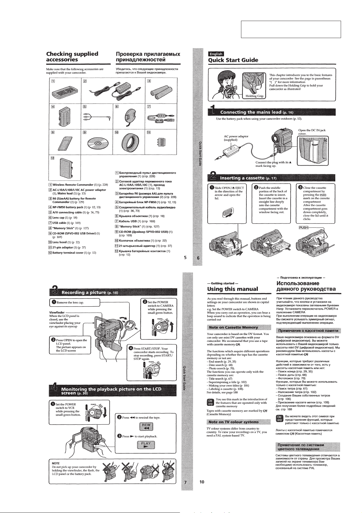
3. SERVICE MODE DISPLAY
The service mode display shows up to six self-diagnosis codes shown in the past.
3-1. Display Method
While pressing the “STOP” key, set the switch from OFF to “VCR”, and continue pressing the “STOP” key for 5 seconds continuously. The
service mode will be displayed, and the counter will show the backup No. and the 5-character self-diagnosis codes.
Viewfinder or LCD screen
[3] C : 3 1 : 1 1
Lights up
[3]
Backup No.
Order of previous errors
C : 3 1 : 1 1
Self-diagnosis Codes
3-2. Switching of Backup No.
By rotating the control dial, past self-diagnosis codes will be shown in order. The backup No. in the [] indicates the order in which the
problem occurred. (If the number of problems which occurred is less than 6, only the number of problems which occurred will be shown.)
[1] : Occurred first time [4] : Occurred fourth time
[2] : Occurred second time [5] : Occurred fifth time
[3] : Occurred third time [6] : Occurred the last time
Control dial
3-3. End of Display
Turning OFF the power supply will end the service mode display.
Note: The “self-diagnosis display” data will be backed up by the coin-type lithium battery (BT1731) of the control switch block (FK-30550). When the
cabinet (L) assembly is removed, the “self-diagnosis display” data will be lost by initialization.
— 9 —

4. SELF-DIAGNOSIS CODE TABLE
Self-diagnosis Code
Function
Repaired by:
C
C
C
C
C
C
C
C
C
C
C
C
C
C
C
C
C
C
C
C
C
C
C
E
E
E
E
Block
04
21
22
31
31
31
31
31
31
31
31
31
31
31
31
32
32
32
32
32
32
32
32
61
61
62
62
Detailed
Code
00
00
00
10
11
20
21
22
23
24
30
40
42
10
11
20
21
22
23
24
30
40
42
00
10
00
01
Symptom/State
Non-standard battery is used.
Condensation.
Video head is dirty.
LOAD direction. Loading does not
complete within specified time
UNLOAD direction. Loading does not
complete within specified time
T reel side tape slacking when unloading
Winding S reel fault when counting the
rest of tape.
T reel fault.
S reel fault.
T reel fault.
FG fault when starting capstan.
FG fault when starting drum.
FG fault during normal drum operations.
LOAD direction loading motor time-
out.
UNLOAD direction loading motor
time-out.
T reel side tape slacking when
unloading.
Winding S reel fault when counting the
rest of tape.
T reel fault.
S reel fault.
T reel fault.
FG fault when starting capstan.
FG fault when starting drum
FG fault during normal drum
operations
Difficult to adjust focus
(Cannot initialize focus.)
Zoom operations fault
(Cannot initialize zoom lens.)
Steadyshot function does not work well.
(With pitch angular velocity sensor output
stopped.)
Steadyshot function does not work well.
(With yaw angular v elocity sensor output
stopped.)
Correction
Use the info LITHIUM battery.
Remove the cassette, and insert it again after one hour.
Clean with the optional cleaning cassette.
Load the tape again, and perform operations from the beginning.
Load the tape again, and perform operations from the beginning.
.
Load the tape again, and perform operations from the beginning.
Load the tape again, and perform operations from the beginning.
Load the tape again, and perform operations from the beginning.
Load the tape again, and perform operations from the beginning.
Load the tape again, and perform operations from the beginning.
Load the tape again, and perform operations from the beginning.
Load the tape again, and perform operations from the beginning.
Load the tape again, and perform operations from the beginning.
Remove the battery or power cable, connect, and perform
operations from the beginning.
Remove the battery or power cable, connect, and perform
operations from the beginning.
Remove the battery or power cable, connect, and perform
operations from the beginning.
Remove the battery or power cable, connect, and perform
operations from the beginning.
Remove the battery or power cable, connect, and perform
operations from the beginning.
Remove the battery or power cable, connect, and perform
operations from the beginning.
Remove the battery or power cable, connect, and perform
operations from the beginning.
Remove the battery or power cable, connect, and perform
operations from the beginning.
Remove the battery or power cable, connect, and perform
operations from the beginning.
Remove the battery or power cable, connect, and perform
operations from the beginning.
Inspect the lens block focus MR sensor (Pin 8,9 of CN1301 of
CD-285 board) when focusing is performed when the control dial
is rotated in the focus manual mode, and the focus motor drive circuit
(IC751 of VC-253 board) when the focusing is not performed.
Inspect the lens block zoom MR sensor (Pin ql,wa of CN1301 of
CD-285 board) when zooming is performed when the zoom lens is
operated and the zoom motor drive circuit (IC751 of VC-253 board)
when zooming is not performed.
Inspect pitch angular velocity sensor (SE1401 of VF-147 board)
peripheral circuits.
Inspect yaw angular velocity sensor (SE1431 of VF-147 board)
peripheral circuits.
— 10 —
SECTION 1
GENERAL
DCR-PC110/PC110E
This section is extracted from instruction
manual. (DCR-PC110E model)
1-1
1-2
1-3
1-4
1-5
1-6
1-7
1-8
1-9
1-10
1-11
1-12
1-13
1-14
1-15
1-16
1-17
1-18
1-19
1-20