

Page 1

DC POWER SUPPLY UNIT
DC-78
SERVICE MANUAL
1st Edition
Page 2
! WARNING
This manual is intended for qualified service personnel only.
To reduce the risk of electric shock, fire or injury, do not perform any servicing other than that
contained in the operating instructions unless you are qualified to do so. Refer all servicing to
qualified service personnel.
! WARNUNG
Die Anleitung ist nur für qualifiziertes Fachpersonal bestimmt.
Alle Wartungsarbeiten dürfen nur von qualifiziertem Fachpersonal ausgeführt werden. Um die
Gefahr eines elektrischen Schlages, Feuergefahr und Verletzungen zu vermeiden, sind bei
Wartungsarbeiten strikt die Angaben in der Anleitung zu befolgen. Andere als die angegeben
Wartungsarbeiten dürfen nur von Personen ausgeführt werden, die eine spezielle Befähigung
dazu besitzen.
! A VERTISSEMENT
Ce manual est destiné uniquement aux personnes compétentes en charge de l’entretien. Afin
de réduire les risques de décharge électrique, d’incendie ou de blessure n’effectuer que les
réparations indiquées dans le mode d’emploi à moins d’être qualifié pour en effectuer d’autres.
Pour toute réparation faire appel à une personne compétente uniquement.
DC-78
Page 3
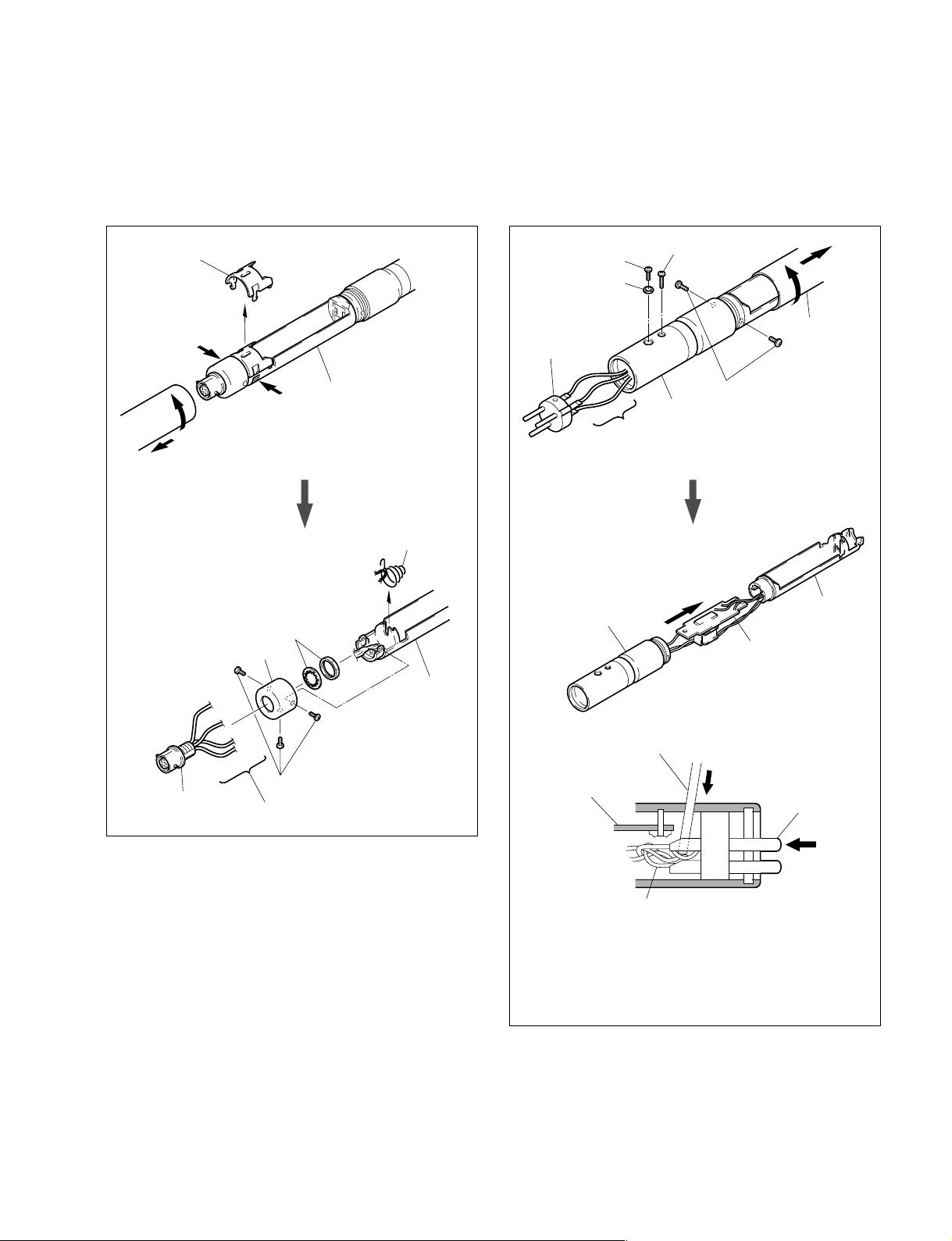
1. Service Overview
1-1. Removal the Input Connector 1-2. Removal the Transformer Mounted
Circuit Board
3 Remove the case lid.
2 Press both claws.
1 Battery sleeve
4 Nut and Washer
VIO
ORG
RED
YEL
5 Connector (S) 4P
Battery case
Cap
1 K 2x3
3 Remove the four leads.
2 Spring
Battery case
1 Connector screw
LW2
2 Cannon pin
insert (3-pin)
VIO
BLK
GRN
Cannon pin sleeve
Screwdriver (2 mm dia.)
Transformer mounted
circuit board
6 P 2x7
4 Battery
sleeve
5 K 2x3
Cannon pin sleeve
3 Remove the three leads.
Battery case
Transformer mounted
circuit board
Cannon pin
insert (3-pin)
DC-78
Three leads
Note : Cannon pin Insert (3-pin) reinstallation
When reinstalling the pin insert (3-pin), turn the connector
three times counterclockwise to twist the leads and push
the leads downwards with a screwdriver (2mm dia.)
through the 4mm dia. holes not to catch on the transformer
mounted circuit board.
1 (E)
Page 4

2. Board Layout
CN (S) 4P
SOLDER SIDE
124
3
ORG
VIO
TRANSFORMER MOUNTED CIRCUIT BOARD
T
RED
2
YEL
4
BATTERY
7
3
1.5 V
ORG
3
SOLDER SIDE
BLK
0
WHT
9
VIO
7
GRN
5
21
3
CN
PIN INSERT
(XLR-3-14)
SOLDER
SIDE
3. Schematic Diagram
1S133T
68µ/6.3 V
HZ28LL
ORG
22 k
BATTERY
1.5 V
CN (S) 4P
OUT SIDE
VIEW
2
1
43
RED
T1
GRNYEL
BLK
VIOVIO
PIN INSERT
1
2
(XLR-3-14)
3
OUT SIDE VIEW
CN
2 (E)
DC-78
Page 5

4-1. Notes on Repair Parts
1. Safety Related Components Warning
w
Components marked ! are critical to safe operation.
Therefore, specified parts should be used in the case of
replacement.
2. Standardization of Parts
Some repair parts supplied by Sony differ from those
used for the unit. These are because of parts commonality and improvement.
Parts list has the present standardized repair parts.
3. Stock of Parts
Parts marked with “o” at SP (Supply Code) column of
the spare parts list may not be stocked. Therefore, the
delivery date will be delayed.
4. Spare Parts
4. Harness
Harnesses with no part number are not registered as
spare parts.
In need of repair, get components shown in the list and
repair using them.
DC-78
3 (E)
Page 6

4-2. Exploded Views and Parts List
K 2x3
1
6
9
10
5
K 2x3
K 2x3
8
A
K 2x3
12
K 2x3
4
LW2
P 2x7
7
A
13
11
4-3. Supplied Accessories
No. Part No. SP Description
1pc 2-347-623-01 s MANUAL, INSTRUCTION
2
3
No. Part No. SP Description
1 A-4587-928-A s CONNECTOR ASSY
2 A-4591-438-A s TRANSFORMER MOUNTED PC BOARD
3 X-2335-596-1 s CASE SUB ASSY, BATTERY
4 1-509-096-00 s CANNON XLR3-14 PIN INSERT
5 1-561-376-11 s CONNECTOR (S) 4P
6 2-347-609-01 s SLEEVE, BATTERY
7 2-347-610-01 s SLEEVE, CANNON PIN
8 2-347-611-01 s CAP
9 2-347-613-01 s LID, CASE
10 2-347-614-01 s SPRING, BATTERY
11 2-347-615-01 s PLATE, BATTERY
12 2-347-618-01 s LABEL, MODEL NUMBER
13 2-347-619-01 s SHEET, BLIND
4 (E)
DC-78
Page 7

Page 8

DC-78 (SYM) J, E
9-976-910-01
Printed in Japan
2002. 10 11
Sony Corporation ©2002
 Loading...