

Page 1

2-691-014-12(1)
(1)
Sony Corporation Printed in Malaysia
http://www.sony.net/
DVD Home Theatre System
Operating Instructions
©2006 Sony Corporation
Page 2
3
WARNING
To reduce the risk of fire or electric
shock, do not expose this apparatus to
rain or moisture.
AC power cord must be changed only at the qualified
service shop.
Do not install the appliance in a confined space, such
as a bookcase or built-in cabinet.
To prevent fire, do not cover the ventilation of the
apparatus with news papers, table-cloths, curtains, etc.
And don’t place lighted candles on the apparatus.
To prevent fire or shock hazard, do not place objects
filled with liquids, such as vases, on the apparatus.
The nameplate is located on the bottom of the unit.
Batteries or batteries installed apparatus shall not be
exposed to excessive heat such as sunshine, fire or the
like.
Don’t throw away the battery with
general house waste, dispose of it
correctly as chemical waste.
This appliance is
classified as a CLASS 1
LASER product. This
marking is located on the
bottom of the unit.
NOTICE FOR THE CUSTOMERS IN THE
UNITED KINGDOM
A moulded plug complying with BS1363 is fitted to
this equipment for your safety and convenience.
Should the fuse in the plug supplied need to be
replaced, a fuse of the same rating as the supplied one
and approved by ASTA or BSI to BS1362, (i.e.,
marked with mark or mark) must be used.
If the plug supplied with this equipment has a
detachable fuse cover, be sure to attach the fuse cover
after you change the fuse. Never use the plug without
the fuse cover.
If you should lose the fuse cover, please contact your
nearest Sony service station.
Precautions
Safety
• If anything falls into the cabinet, unplug the unit and
have it checked by qualified personnel before
operating it any further.
• The unit is not disconnected from the AC power
source (mains) as long as it is connected to the wall
outlet (mains), even if the unit itself has been turned
off.
• Unplug t he unit from the wall outlet (mains) if you do
not intend to use it for an extended period of time. To
disconnect the cord, pull it out by the plug, never by
the cord.
• Install this system so that the power cord can be
unplugged from the wall socket immediately in the
event of trouble.
Installing
• Allow adequate air circulation to prevent internal
heat buildup.
• Do not place the unit on surfaces (rugs, blankets, etc.)
or near materials (curtains, draperies) that may block
the ventilation slots.
• Do not install the unit near heat sources such as
radiators, or air ducts, or in a place subject to direct
sunlight, excessive dust, mechanical vibration, or
shock.
• Do not install the unit in an inclined position. It is
designed to be operated in a horizontal position only.
• Keep the unit and discs away from equipment with
strong magnets, such as microwave ovens, or large
loudspeakers.
• Do not place heavy objects on the unit.
• If the unit is brought directly from a cold to a warm
location, moisture may condense inside the DVD
Home Theatre System and cause damage to the
lenses. When you first install the unit, or when you
move it from a cold to a warm location, wait for about
30 minutes before operating the unit.
• Do not place the system in confined space such as a
bookshelf or similar unit.
GB
2
Page 3

Disposal of Old
Electrical & Electronic
Equipment (Applicable
in the European Union
and other European
countries with separate
collection systems)
This symbol on the product or on
its packaging indicates that this
product shall not be treated as household waste. Instead
it shall be handed over to the applicable collection
point for the recycling of electrical and electronic
equipment. By ensuring this product is disposed of
correctly, you will help prevent potential negative
consequences for the environment and human health,
which could otherwise be caused by inappropriate
waste handling of this product. The recycling of
materials will help to conserve natural resources. For
more detailed information about recycling of this
product, please contact your local Civic Office, your
household waste disposal service or the shop where
you purchased the product.
The manufacturer of this product is Sony Corporation,
1-7-1 Konan Minato-ku Tokyo, 108-0075 Japan. The
Authorized Representative for EMC and product
safety is Sony Deutschland GmbH, Hedelfinger
Strasse 61, 70327 Stuttgart, Germany. For any service
or guarantee matters please refer to the addresses given
in separate service or guarantee documents.
Welcome!
Thank you for purchasing Sony DVD Home
Theatre System. Before operating this system,
please read this manual thoroughly and retain it
for future reference.
GB
3
Page 4

Table of Contents
Welcome!................................................ 3
About This Manual ................................. 6
This System Can Play the Following
Discs ................................................. 6
Guide to the Control Menu Display...... 10
Getting Started
Unpacking ............................................. 13
Inserting Batteries into the Remote.......14
Hookup Overview................................. 15
Step 1: Speaker System Hookup........... 16
Step 2: Antenna (Aerial) Hookup .........19
Step 3: TV Hookup ............................... 20
Step 4: Other Component Hookup........ 26
Step 5: Connecting the AC Power Cord
(Mains Lead)................................... 29
Step 6: Performing the Quick Setup .....30
Step 7: Installing the Speakers .............. 33
Basic Operations
Playing Discs ........................................ 36
System Sound Feature........................... 38
Enjoying Discs
Resuming Playback From the Point Where
You Stopped the Disc ..................... 41
(Resume Play)
Creating Your Own Program ................ 42
(Program Play)
Playing in Random Order .....................43
(Shuffle Play)
Playing Repeatedly ............................... 44
(Repeat Play)
Using the DVD’s Menu ........................ 45
Selecting [ORIGINAL] or [PLAY LIST]
on a DVD-RW ................................ 46
Selecting a Playback layer for a Super
Audio CD........................................ 46
Playing VIDEO CDs with PBC Functions
(Ver.2.0).......................................... 47
(PBC Playback)
About MP3 Audio Tracks and JPEG
Image Files ..................................... 48
Playing DATA CDs with MP3 Audio
Track and JPEG Image Files .......... 49
Playing Audio Tracks and Images as a
Slide Show with Sound .................. 51
Enjoying DivX® Videos ...................... 53
Adjusting the Delay Between the Picture
and Sound....................................... 55
(A/V SYNC)
Searching for a Particular Point
on a Disc......................................... 56
(Scan, Slow-motion Play, Freeze
Frame)
Searching for a Title/Chapter/Track/
Scene, etc........................................ 57
Searching by Scene............................... 59
(Picture Navigation)
Viewing Information About the Disc ... 60
Using Various Additional
Functions
Changing the Angles ............................ 63
Displaying the Subtitles........................ 63
Locking Discs ....................................... 64
(CUSTOM PARENTAL
CONTROL, PARENTAL
CONTROL)
Other Operations
Controlling the TV with the Supplied
Remote ........................................... 68
Using the THEATRE SYNC
Function.......................................... 69
Changing the Sound ............................. 71
Using the Sound Effect......................... 72
Enjoying the Sound of Other
Components.................................... 73
Enjoying Multiplex Broadcast Sound .. 74
(DUAL MONO)
Enjoying the Radio ............................... 75
Using the Radio Data System (RDS) ... 77
(Except for Russian model)
Using the Sleep Timer .......................... 77
Changing the Brightness of the Front
Panel Display.................................. 78
Returning to the Default Settings ......... 78
GB
4
Page 5

Settings and Adjustments
Using the Setup Display........................ 79
Setting the Display or Sound Track
Language ........................................ 80
[LANGUAGE SETUP]
Settings for the Display......................... 81
[SCREEN SETUP]
Custom Settings .................................... 82
[CUSTOM SETUP]
Speaker Setting (Subwoofer) ................83
[SPEAKER SETUP]
Additional Information
Precautions ............................................ 84
Notes about the Discs............................85
Troubleshooting .................................... 85
Self-diagnosis Function ........................ 88
(When letters/numbers appear in
the display)
Specifications ........................................ 89
Glossary ................................................ 90
Language Code List ..............................93
Index to Parts and Controls...................94
DVD Setup Display List .......................99
AMP Menu List ..................................100
Index ................................................... 101
GB
5
Page 6
About This Manual
This System Can Play the
• The instructions in this manual describe the
controls on the remote. You can also use the
controls on the system if they have the same or
similar names as those on the remote.
• The Control Menu items may be different
depending on the area.
• “DVD” may be used as a general term for
DVD VIDEOs, DVD+RWs/DVD+Rs, and
DVD-RWs/DVD-Rs.
• The following symbols are used in this
manual.
Symbol Meaning
Functions available for DVD
VIDEOs, DVD-Rs/DVD-RWs in
video mode, and DVD+Rs/
DVD+RWs
Functions available for DVD-RWs
in VR (Video Recording) mode
Functions available for VIDEO
CDs (including Super VCDs or CDRs/CD-RWs in video CD format or
Super VCD format)
Functions available for Super Aud io
CDs
Functions available for music CDs
or CD-Rs/CD-RWs in music CD
format
Functions available for DATA CDs
(CD-ROMs/CD-Rs/CD-RWs
containing MP3*1 audio tracks,
JPEG image files, and DivX*2*3
video files)
Functions available for DATA
DVDs (DVD-Rs/DVD-RWs/
DVD+Rs/DVD+RWs) containing
DivX*2*3 video files
*1 MP3 (MPEG1 Audio Layer 3) is a standard format
defined by ISO/MPEG which compresses audio
data.
*2 DivX® is a video file compression technology,
developed by DivXNetworks, Inc.
*3 DivX, DivX Certified, and associated logos are
trademarks of DivXNetworks, Inc. and are used
under license.
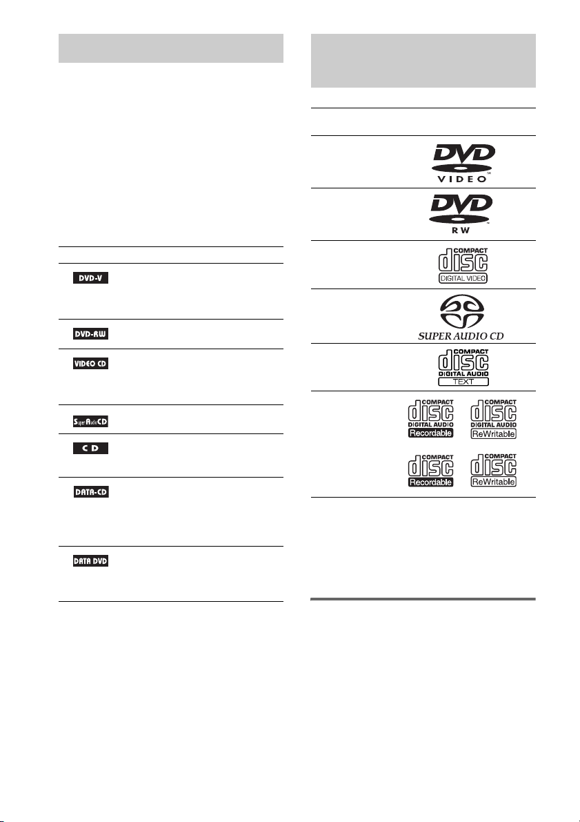
Following Discs
Format of
discs
DVD VIDEO
DVD-RW
VIDEO CD
Super Audio
*1
CD
Audio CD
CD-R/CD-RW
(audio data)
(MP3 files)
(JPEG files)
The “DVD VIDEO” logo and “DVD-RW” logo are
trademarks.
*1 Except for multi-channel playback area.
*2 CD text data can be displayed (disc title only).
*2
Note about CDs/DVDs
The system can play CD-ROMs/CD-Rs/CDRWs recorded in the following formats:
– audio CD format
– video CD format
Disc logo
GB
6
Page 7

– MP3 audio tracks, JPEG image files, and
DivX video files of format conforming to ISO
9660 Level 1/Level 2, or its extended format,
Joliet
The system can play DVD-ROMs/DVD+RWs/
DVD-RWs/DVD+Rs/DVD-Rs recorded in the
following formats:
– DivX video files of format conforming to
UDF.
Example of discs that the
system cannot play
The system cannot play the following discs:
• CD-ROMs/CD-Rs/CD-RWs other than those
recorded in the formats listed on page 6
• CD-ROMs recorded in PHOTO CD format
• Data part of CD-Extras
• DVD Audios
• DVD-RAMs
• A DVD VIDEO with a different region code
(page 8, 91).
• A disc that has a non-standard shape (e.g., card
shaped, heart shaped).
• A disc that has a commercially available
accessory attached, such as a label or ring.
Ring
Label
• An adapter to convert an 8 cm disc to standard
size.
Adapter
Notes about CD-R/CD-RW/DVD-R/
DVD-RW/DVD+R/DVD+RW
In some cases, CD-R/CD-RW/DVD-R/DVD-RW/
DVD+R/DVD+RW cannot be played on this system
due to the recording qua lity or physical condition of the
disc, or the characteristics of the recording device and
authoring software.
The disc will not play if it has not been correctly
finalized. For more information, see the operating
instructions for the recording device.
Note that discs created in the Packet Write format
cannot be played.
Music discs encoded with
copyright protection
technologies
This product is designed to play back discs that
conform to the Compact Disc (CD) standard.
Recently, various music discs encoded with copyright
protection technologies are marketed by some record
companies. Please be aware that among those discs,
there are some that do not conform to the CD standard
and may not be playable by this product.
Note on DualDisc
A DualDisc is a two sided disc product which mates
DVD recorded material on one side with digital audio
material on the other side. However, since the audio
material side does not conform to the Compact Disc
(CD) standard, playback on this product is not
guaranteed.
Note about DVD-RW (Except for
U.S./Canadian/European models)
Images in DVD-RWs with CPRM* protection may not
be played if they contain a copy protection signal.
“Copyright lock” appears on the screen.
*
CPRM (Content Protection for Recordable Media) is
a coding technology that protects the copyright of
images.
• A disc with paper or stickers on it.
• A disc that has the adhesive of cellophane tape
or a sticker still left on it.
continued
GB
7
Page 8
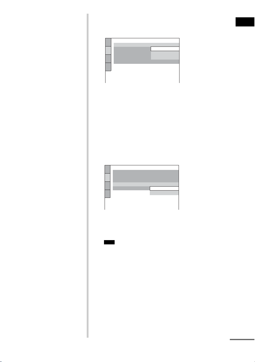
Note on PBC (Playback
)
Control) (VIDEO CDs)
This system conforms to Ver. 1.1 and Ver. 2.0 of
VIDEO CD standards. You can enjoy two kinds
of playback depending on the disc type.
Disc type You can
VIDEO CDs
without PBC
functions
(Ver. 1.1 discs)
VIDEO CDs
with PBC
functions
(Ver. 2.0 discs)
Enjoy video playback (moving
pictures) as well as music.
Play interactive software using
menu screens displayed on the
TV screen (PBC Playback), in
addition to the video playback
functions of Ver. 1.1 discs.
Moreover, you can play highresolution still pictures, if they
are included on the disc.
About Multi Session CD
• This system can play Multi Session CDs when
an MP3 audio track is contained in the first
session. Any subsequent MP3 audio tracks
recorded in later sessions can also be played
back.
• This system can play Multi Session CDs when
a JPEG image file is contained in the first
session. Any subsequent JPEG image files
recorded in later sessions can also be played
back.
• If audio tracks and images in music CD format
or video CD format are recorded in the first
session, only the first session will be played
back.
About the Super Audio CD
Super Audio CD is a new high-quality audio
disc standard where music is recorded in the
DSD (Direct Stream Digital) format
(conventional CDs are recorded in the PCM
format). The DSD format, using a sampling
frequency 64 times higher than that of a
conventional CD, and with 1-bit quantization,
achieves both a wide frequency range and a wide
dynamic range across the audible frequency
range, and so provides music reproduction
extremely faithful to the original sound.
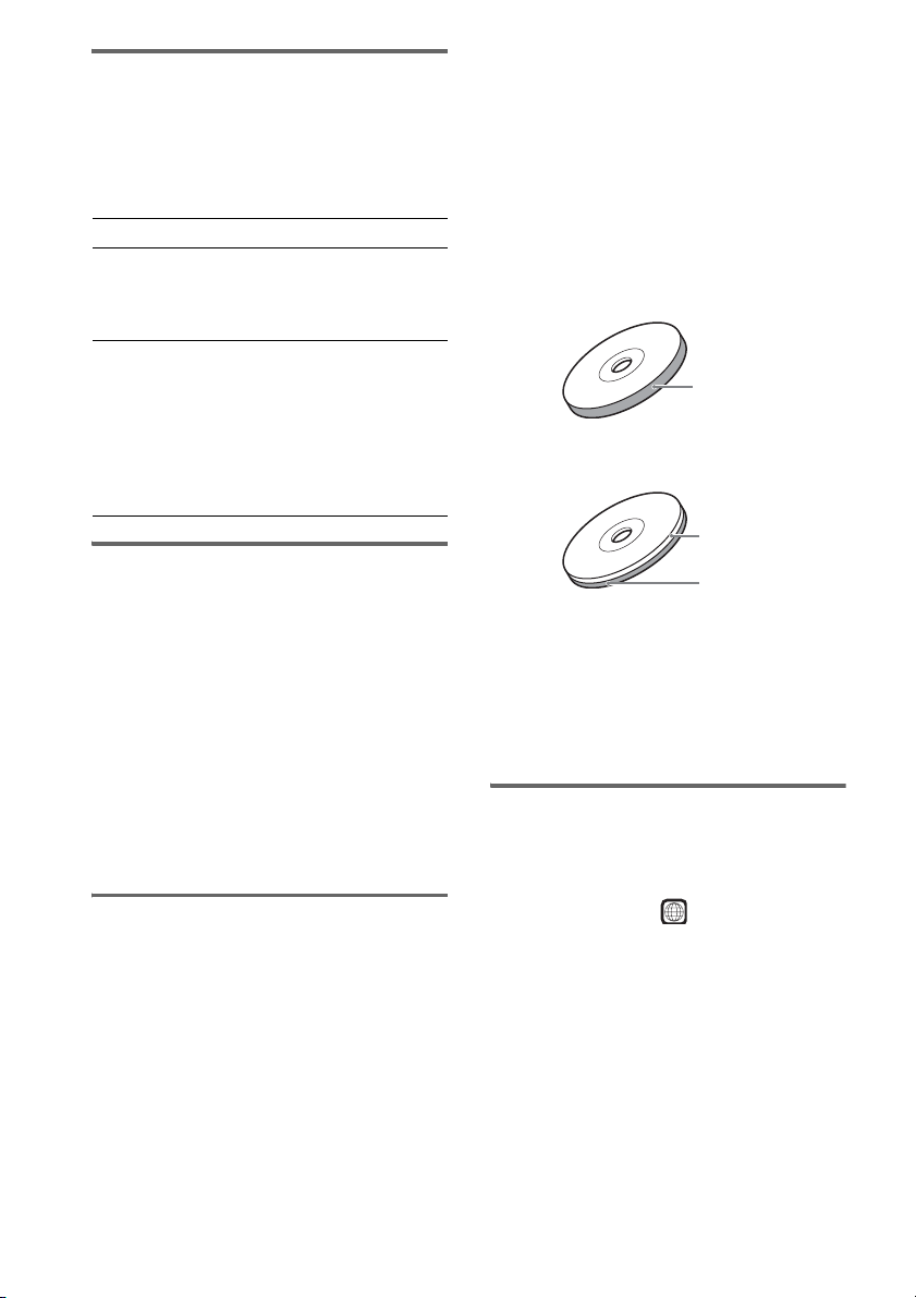
Types of Super Audio CDs
There are two types of discs, depending on the
Super Audio CD layer and CD layer
combination.
• Super Audio CD layer*: A high-density
signal layer for Super Audio CD
•CD layer*
1
: A layer that is readable by a
conventional CD player
Single layer disc
(a disc with a single Super Audio CD layer)
Super Audio CD
layer
Hybrid disc*
(a disc with an Super Audio CD layer and a CD layer
*1 You can play the CD layer on a conventional CD
player.
*2 Since both layers are on one side, it is not necessary
to turn the disc over.
*3 To select a layer, see “Selecting a Playback layer for
a Super Audio CD” (page 46).
2
CD layer*
Super Audio CD
layer*
3
3
Region code
Your system has a region code printed on the
back of the unit and will only play DVDs labeled
with the same region code.
DVD VIDEOs labeled will also play on this
system.
If you try to play any other DVD VIDEO, the
message [Playback prohibited by area
limitations.] will appear on the TV screen.
Depending on the DVD VIDEO, no region code
indication may be given even though playing the
DVD VIDEO is prohibited by area restrictions.
ALL
GB
8
Page 9

Note on playback operations
of DVDs and VIDEO CDs
Some playback operations of DVDs and VIDEO
CDs may be intentionally set by software
producers. Since this system plays DVDs and
VIDEO CDs according to the disc contents the
software producers designed, some playback
features may not be available. Also, refer to the
instructions supplied with the DVDs or VIDEO
CDs.
Copyrights
This product incorporates copyright protection
technology that is protected by U.S. patents and
other intellectual property rights. Use of this
copyright protection technology must be
authorized by Macrovision, and is intended for
home and other limited viewing uses only unless
otherwise authorized by Macrovision. Reverse
engineering or disassembly is prohibited.
2
Digital
1
Digital
This system incorporates with Dolby*
and Dolby Pro Logic (II) adaptive matrix
surround decoder and the DTS*
Surround System.
This system perfectly decodes 5.1 channel
signal, but you cannot add other commercially
available surround speakers.
*1 Manufactured under license from Dolby
Laboratories.
“Dolby,” “Pro Logic,” and the double-D symbol are
trademarks of Dolby Laboratories.
*2 Manufactured under license from Digital Theater
Systems, Inc.
“DTS” and “DTS Digital Surround” are registered
trademarks of Digital Theater Systems, Inc.
GB
9
Page 10
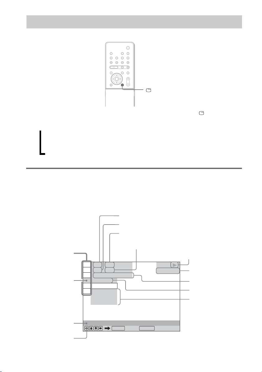
Guide to the Control Menu Display
DISPLAY
Use the Control Menu to select a function and to view related information. Press DISPLAY
repeatedly to turn on or change the Control Menu display as follows:
Control Menu display 1
,
m
Control Menu display 2 (appears for certain discs only)
m
Control Menu display off
Control Menu display
The Control Menu display 1 and 2 will show different items depending on the disc type. For details
about each item, see the pages in parentheses.
Example: Control Menu display 1 when playing a DVD VIDEO.
Currently playing title number*
Currently playing chapter number*
Total number of titles*
Total number of chapters*
Control Menu items
)
)
1 : 3 2 : 5 5
Selected item
1 2 ( 2 7
1 8 ( 3 4
T
OFF
OFF
DISC
TITLE
CHAPTER
Function name of
10
GB
selected Control
Menu item
Operation message
REPEAT
ENTER DISPLAY
Quit:
1
1
2
DVD VIDEO
2
Playback status
(N Playback, X
Pause,
x Stop, etc.)
Type of disc being
3
played*
Playing time*
Current setting
Options
4
Page 11

*1 Displays the scene number for VIDEO CDs (PBC is on), track number for VIDEO CDs/Super Audio CDs/CDs,
album number for DATA CDs. DivX video album number for DATA DVDs/DATA CDs.
*2 Displays the index number for VIDEO CDs/Super Audio CDs, MP3 audio track number, or JPEG image file
number for DATA CDs. DivX video file number for DATA DVDs/DATA CDs.
*3 Displays Super VCD as “SVCD.” Displays “MP3” in the Control Menu display 1 or “JPEG” in the Control Menu
2 for DATA CDs.
*4 Displays the date for JPEG files.
To turn off the display
Press DISPLAY.
List of Control Menu items
Item Item Name, Function, Relevant Disc Type
[TITLE] (page 57)/[SCENE] (page 57)/[TRACK] (page 57)
Selects the title, scene, or track to be played.
[CHAPTER] (page 57)/[INDEX] (page 57)
Selects the chapter or index to be played.
[INDEX] (page 57)
Displays the index and selects the index to be played.
[TRACK] (page 57)
Selects the track to be played.
[ORIGINAL/PLAY LIST] (page 46)
Selects the type of titles (DVD-RW) to be played, the [ORIGINAL] one, or an edited [PLAY
LIST].
[TIME/TEXT] (page 57)
Checks the elapsed time and the remaining playback time.
Input the time code for picture and music searching.
Displays the DVD/CD text or the MP3 track name.
[PROGRAM] (page 42)
Selects the track to play in the order you want.
[SHUFFLE] (page 43)
Plays the track in random order.
[REPEAT] (page 44)
Plays the entire disc (all titles/all tracks/all albums) repeatedly or one title/chapter/track/album
repeatedly.
[PARENTAL CONTROL] (page 64)
Sets to prohibit playback on this system.
[SETUP] (page 79)
[QUICK] Setup (page 30)
Use Quick Setup to choose the desired language of the on-screen display, the aspect ratio of
the TV, and the size of the speakers you are using.
[CUSTOM] Setup
In addition to the Quick Setup setting, you can adjust various other settings.
[RESET]
Returns the settings in [SETUP] to the default setting.
[ALBUM] (page 57)
Selects the album to be played.
continued
11
GB
Page 12

[FILE] (page 57)
Selects the JPEG image file and DivX video file to be played.
[DATE] (page 62)
Displays the date when the picture was taken.
[INTERVAL] (page 52)
Specifies the duration for which the slides are displayed on the screen.
[EFFECT] (page 52)
Selects the effects to be used for changing slides during a slide show.
[MODE (MP3, JPEG)] (page 51)
Selects the data type; MP3 audio track (AUDIO), JPEG image file (IMAGE) or both
(AUTO) to be played when playing a DATA CD
Tip
• The Control Menu icon indicator lights up in green when you select any item except [OFF]
t
([PROGRAM], [SHUFFLE], [REPEAT] only). The [ORIGINAL/PLAY LIST] indicator lights up in green when
you select [PLAY LIST] (default setting).
12
GB
Page 13

Getting Started
Unpacking
Check that you have the following items:
• Speakers (2)
• Subwoofer (1)
• AM loop antenna (aerial) (1)
• FM wire antenna (aerial) (1)
• Speaker cord (1)
• Video Cord (1)
• Remote Commander (remote) (1)
• Size AAA (R03) batteries (2)
• Operating Instructions
• Setup Disc (1)
• Quick Start Guide (card)
• Speaker pads (8)
Getting Started
13
GB
Page 14

Inserting Batteries into the Remote
You can control the system using the supplied remote. Insert two size AAA (R03) batteries by matching
the 3 and # ends on the batteries to the markings inside the compartment. When using the remote,
point it at the remote sensor on the system.
1Slide open the cover.
2
2Remove the cover by
pinching the sides.
Note
• Do not leave the remote in an extremely hot or humid place.
• Do not use a new battery with an old one.
• Do not drop any foreign object into the remote casing, particularly when replacing the batteries.
• Do not expose the remote sensor to direct light from the sun or lighting apparatus. Doing so may cause a
malfunction.
• If you do not intend to use the remote for an extended period of time, remove the batteries to avoid possible damage
from battery leakage and corrosion.
14
GB
Page 15

Hookup Overview
Perform all connections and settings by following Steps 1 to 7.
“Step 1: Speaker System Hookup” (page 16)
“Step 2: Antenna (Aerial) Hookup” (page 19)
“Step 3: TV Hookup” (page 20)
“Step 4: Other Component Hookup” (page 26)
“Step 5: Connecting the AC Power Cord (Mains Lead)” (page 29)
“Step 6: Performing the Quick Setup” (page 30)
“Step 7: Installing the Speakers” (page 33)
Video signal is sent to the TV, and is output from the TV screen; audio signals are processed by this
system and output from the speakers of this system. You can also enjoy sound of other sources, such
as TV programs, in addition to DVDs or CDs.
Getting Started
15
GB
Page 16

Step 1: Speaker System Hookup
Connect the supplied speaker system using the supplied speaker cord. Do not connect any speakers
other than those supplied with this system.
To obtain the best possible front surround sound, use the supplied Setup Disc to determine the ideal
speaker positions (page 33).
Required cord
Speaker cord
You can connect the system and speakers with this one cord.
To the front speaker
(gray, 5 m)
To the system
To the subwoofer
(black, 3 m)
To the front speaker
(gray, 5 m)
Tip
• By connecting an extension cord (optional) to the respective jack(s) of the speaker cord, you can extend the length
of the cord.
RK-SX1
Attaching the speaker pads
To prevent speaker vibration or movement while listening, attach the supplied foot pads to the bottom
four corners of the front speakers.
GB
16
Page 17
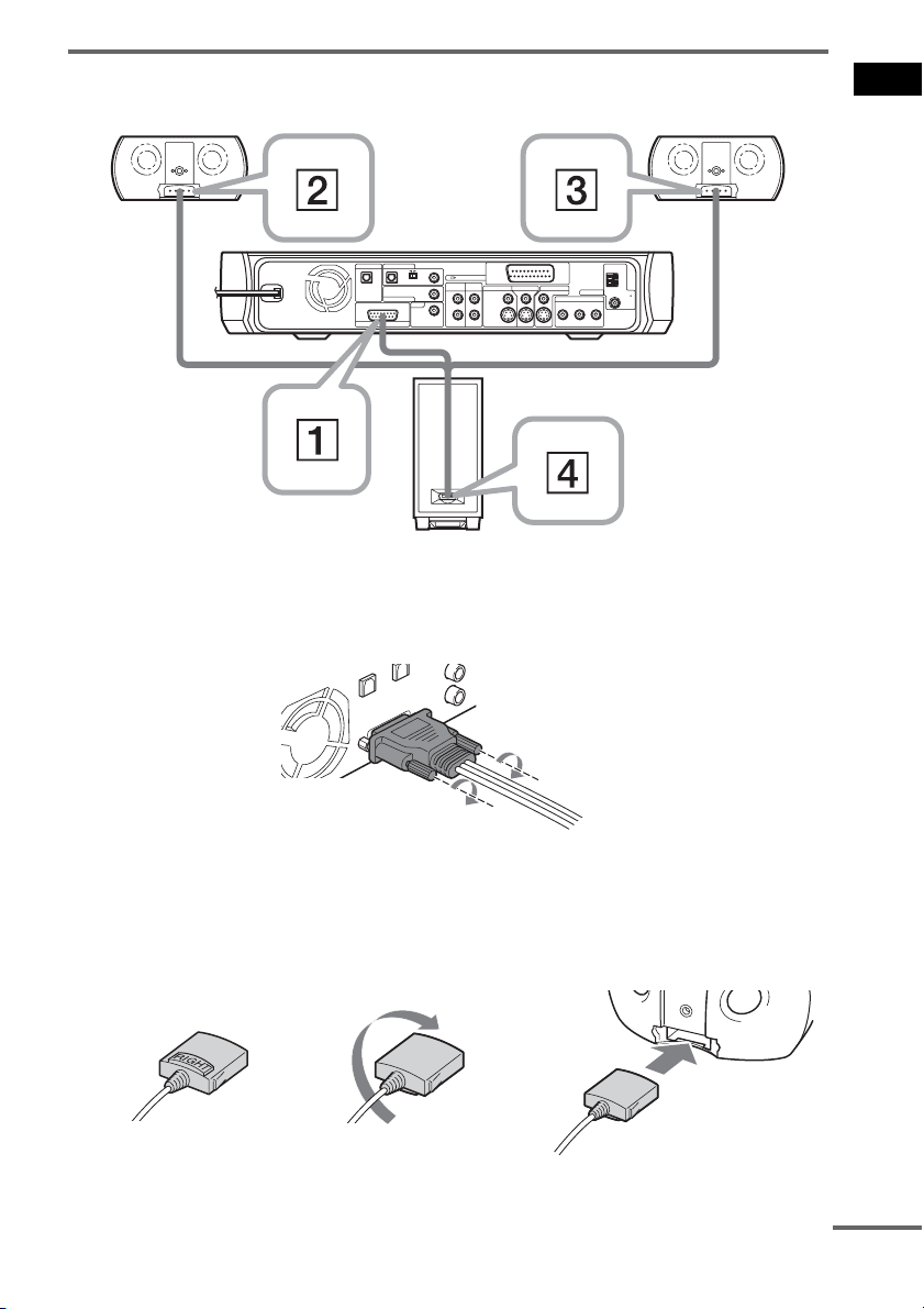
Connecting the speakers
Front speaker (R)
VIDEO 1 / SAT 1
DIGITAL OUT
OPTICAL
COAXIAL
)
OUTPUT(TO TV
DIGITAL IN
VIDEO 1 /
VIDEO 2 /
VIDEO 1 / SAT 1 VIDEO 2 / SAT 2
OPTICAL
SPEAKER
VIDEO 2 / SAT 2
L
TV
R
DIGITAL IN
COAXIAL
AUDIO INAUDIO IN
SAT 1
SAT 2
DIGITAL IN
COAXAL
MONITOR OUT
VIDEO
VIDEO IN
S-VIDEO IN
ANTENNA
COMPONENT VIDEO OUT
YPB/CBPR/C
S-VIDEO
Subwoofer
Connect the speaker cord in order of 1 to 4, according to the above illustration.
A Connect the speaker cord to the system.
Secure the jack by tightening the two screws.
AM
FM
75
COAXIAL
R
Front speaker (L)
Getting Started
B Connect the speaker jack marked RIGHT to the front speaker, then place it in the right
front speaker position.
The front speakers are identical, and either can be used for the left or right speaker. If you connect
the RIGHT jack to the speaker, it becomes the right front speaker.
RIGHT (gray)
k
Label side face down.
k
Connect to the right
front speaker.
continued
17
GB
Page 18
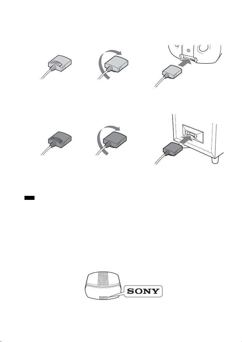
C Connect the speaker jack marked LEFT to the front speaker, then place it in the left front
speaker position.
The front speakers are identical, and either can be used for the left or right speaker. If you connect
the LEFT jack to the speaker, it becomes the left front speaker.
LEFT (gray)
k
Label side face down.
k
Connect to the left
front speaker.
D Connect the speaker jack marked WOOFER to the subwoofer.
k
WOOFER (black) Label side face down.
k
Connect to the
subwoofer.
After connecting all the components, speakers, and AC power cord (mains lead), use the Setup Disc to
check all the speakers are connected correctly. For details on using the Setup Disc, see page 34.
Note
• Do not set the speakers in an inclined position.
• Do not place the speakers in locations that are:
– Extremely hot or cold
– Dusty or dirty
– Very humid
– Subject to vibrations
– Subject to direct sunlight
• When cleaning, use a soft cloth such as a cleaning cloth for glasses.
• Do not use any type of abrasive pad, scouring powder, or solvent such as alcohol or benzene.
• Do not connect the WOOFER jack either front speaker, or the LEFT or RIGHT jacks to the subwoofer.
• Place the speakers only on their bottom surfaces, with the SONY logo correctly oriented.
18
GB
Page 19
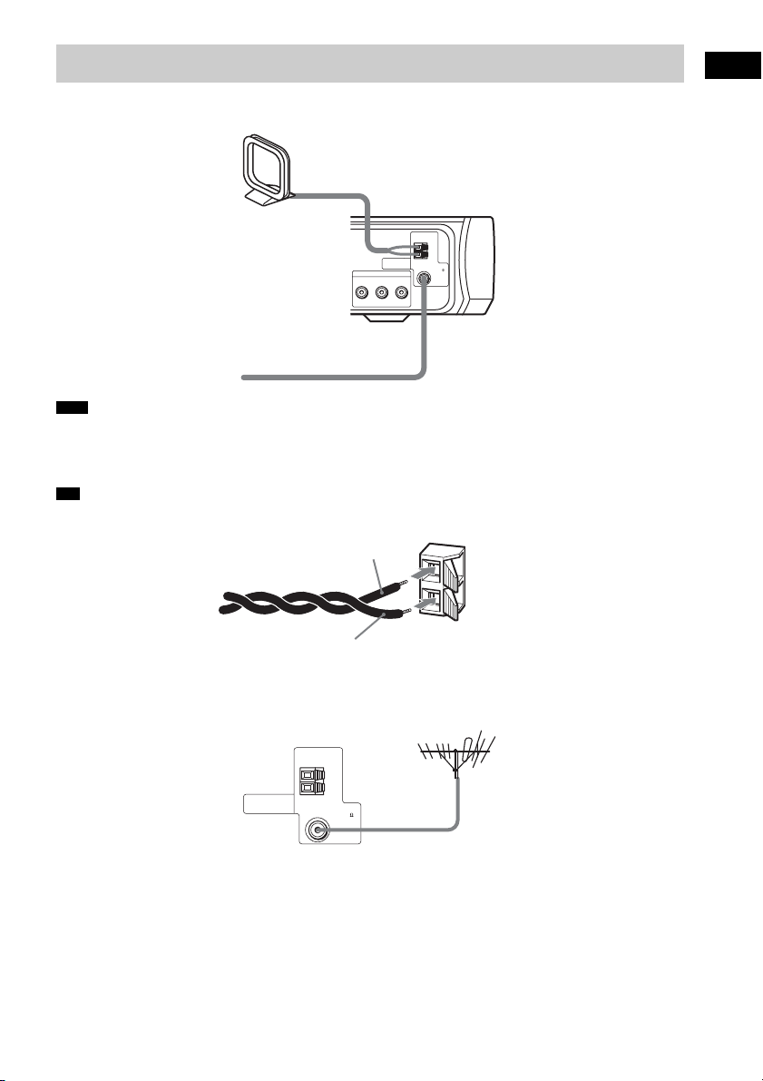
Step 2: Antenna (Aerial) Hookup
Connect the supplied AM/FM antennas (aerials) for listening to the radio.
AM loop antenna (aerial)
AM
ANTENNA
75
COMPONENT VIDEO OUT
YPB/CBPR/C
FM wire antenna (aerial)
Note
• To prevent noise pickup, keep the AM loop antenna (aerial) away from the system and other components.
• Be sure to fully extend the FM wire antenna (aerial).
• After connecting the FM wire antenna (aerial), keep it as horizontal as possible.
Tip
• When you connect the supplied AM loop antenna (aerial), cord (A) or cord (B) can be connected to either terminal.
A
FM
COAXIAL
R
Getting Started
B
• If you have poor FM reception, use a 75-ohms coaxial cable (not supplied) to connect the system to an outdoor FM
antenna (aerial) as shown below.
System
Outdoor FM antenna (aerial)
ANTENNA
AM
FM
COAXIAL
75
19
GB
Page 20

Step 3: TV Hookup
First, perform the video connection, and then audio connection.
With your TV’s audio output connected to this system, you can listen to TV sound through the system
speakers.
Connecting the video cords
Sends a played back DVD image to a TV.
Check the jacks of your TV, and choose the A, B, C, or D connection. Picture quality improves in
order from A to D.
TV
EURO AV
INPUT(FROM VIDEO)
A
To EURO AV
t INPUT (FROM VIDEO)
B
To EURO AV
T OUTPUT
(TO TV)
VIDEO 1 / SAT 1
DIGITAL OUT
OPTICAL
VIDEO 2 / SAT 2
SPEAKER
OPTICAL
DIGITAL IN
DIGITAL IN
COAXAL
TV
COAXIAL
DIGITAL IN
COAXIAL
OUTPUT(TO TV
VIDEO 1 /
VIDEO 2 /
SAT 1
SAT 2
L
R
AUDIO INAUDIO IN
To VIDEO
)
VIDEO 1 / SAT 1 VIDEO 2 / SAT 2
VIDEO IN
S-VIDEO IN
MONITOR OUT
VIDEO
S-VIDEO
To S VIDEO
ANTENNA
COMPONENT VIDEO OUT
YPB/CBPR/C
To COMPONENT
VIDEO OUT
AM
FM
75
COAXIAL
R
CD
VIDEO
IN
TV
S VIDEO
IN
TV with S VIDEO IN jack
Y
PB/CB
PR/CR
TV with COMPONENT
VIDEO IN jacks
20
GB
Page 21

A To connect to a TV with the SCART input jack
Connect the system to your TV using the SCART (EURO AV) cord (not supplied).
Be sure to connect the SCART (EURO AV) cord to the EURO AV T OUTPUT (TO TV) jack on the
system.
When you connect using the SCART (EURO AV) cord, check that the TV conforms to VIDEO signal
or RGB signals. If the TV conforms to VIDEO signal, change the input mode of the TV to RGB signals.
Refer to the operating instructions supplied with the TV to be connected.
B To connect to a TV with the VIDEO IN jacks
Connect the video cord.
Yellow
C To connect to a TV with the S VIDEO IN jack
Connect an S video cord (not supplied). When using the S video jack instead of the video jacks, your
TV monitor must also be connected via an S video jack. S video signals are on a separate bus from the
video signals and will not be output through the video jacks.
D To connect to a TV with the COMPONENT VIDEO IN jacks
Connect a component video cord (not supplied). To use the COMPONENT VIDEO OUT jacks (Y, PB/
C
B, PR/CR) instead of the video jacks, your TV monitor must be equipped with via COMPONENT
VIDEO IN jacks (Y, P
connection and set the output channel of the system to progressive format (page 22).
B/CB, PR/CR). If your TV accepts progressive format signals, you should use this
Green
Blue
Red
Getting Started
Note
• Only when DVD function is selected (by pressing FUNCTION repeatedly until “DVD” appears in the front panel
display), the COMPONENT VIDEO OUT jacks output video signals.
When connecting to a standard 4:3 screen TV
Depending on the disc, the image may not fit your TV screen.
To change the aspect ratio, see page 81.
continued
21
GB
Page 22

Does your TV accept progressive signals?
Progressive is the method for displaying TV images which reduces flickering, and sharpens the image.
To display using this method, you need to connect to a TV that accepts progressive signals.
FUNCTION
PROGRESSIVE
With cover opened.
“P AUTO” or “P VIDEO” appears in the front panel display when the system outputs progressive
signals.
1 Press FUNCTION repeatedly to select “DVD.”
2 Press PROGRESSIVE.
Each time you press PROGRESSIVE, the display changes as follows:
t P AUTO (PROGRESSIVE AUTO)
r
P VIDEO (PROGRESSIVE VIDEO)
r
INTERLACE
22
x P AUTO (PROGRESSIVE AUTO)
Select this setting when:
– your TV accepts progressive signals, and,
– the TV is connected to the COMPONENT VIDEO OUT jacks.
Normally select this under the above condition. This automatically detects the software type, and
selects the appropriate conversion method.
Note that the picture will not be clear or no picture will appear if you select these settings when
either of the above conditions is not met.
x P VIDEO (PROGRESSIVE VIDEO)
Select this setting when:
– your TV accepts progressive signals, and,
– the TV is connected to the COMPONENT VIDEO OUT jacks, and,
– you want to fix the conversion method to PROGRESSIVE VIDEO for video-based software.
Select this if the image is not clear when you select PROGRESSIVE AUTO.
Note that the picture will not be clear or no picture will appear if you select these settings when
GB
Page 23

either of the above conditions is not met.
x INTERLACE
Select this setting when:
– your TV does not accept progressive signals, or,
– your TV is connected to jacks other than the COMPONENT VIDEO OUT jacks (MONITOR
OUT (VIDEO/S VIDEO)/EURO AV
T OUTPUT (TO TV)).
About DVD software types and the conversion method
DVD software can be divided into 2 types: film-based software and video-based software.
Video-based software is derived from TV, such as dramas and sit-coms, and displays images at 30
frames/60 fields per second. Film-based software is derived from film and displays images at 24 frames
per second. Some DVD software contains both video and film.
In order for these images to appear natural on your screen when output in progressive format, the
progressive signals need to be converted to match the type of DVD software that you are watching.
Note
• When you play video-based software in progressive signal format, sections of some types of images may appear
unnatural due to the conversion process when output through the COMPONENT VIDEO OUT jacks. Even though
you set to “PROGRESSIVE AUTO” or “PROGRESSIVE VIDEO,” images from the MONITOR OUT (VIDEO/
S VIDEO) /EURO AV T OUTPUT (TO TV) jacks are unaffected as they are output in the interlace format.
• If you set [LINE] in [SCREEN SETUP] to [RGB] (page 82), the system switches to “INTERLACE.” This will
happen even though you select “PROGRESSIVE AUTO” or “PROGRESSIVE VIDEO.”
• If you set [LINE] in [SCREEN SETUP] to [RGB] (page 82), the system outputs no component video signals.
Getting Started
continued
23
GB
Page 24

Connecting the audio cords
Outputs TV sound through the speakers of this system.
When you want to output stereo (2-channel) TV sound from the system speakers, choose connection
A or B below.
The quality of the audio increases from A to B.
TV
EURO AV
INPUT(FROM VIDEO)
COAXIAL
DIGITAL
OUT
B
A
DIGITAL OUT
OPTICAL
SPEAKER
VIDEO 1 / SAT 1
OPTICAL
VIDEO 2 / SAT 2
DIGITAL IN
DIGITAL IN
COAXAL
TV
COAXIAL
DIGITAL IN
COAXIAL
VIDEO 1 /
L
R
OUTPUT(TO TV
SAT 1
)
VIDEO 2 /
VIDEO 1 / SAT 1 VIDEO 2 / SAT 2
SAT 2
VIDEO IN
S-VIDEO IN
AUDIO INAUDIO IN
To TV (COAXIAL DIGITAL IN)
To EURO AV T OUTPUT (TO TV)
ANTENNA
AM
FM
75
COAXIAL
R
MONITOR OUT
S-VIDEO
VIDEO
COMPONENT VIDEO OUT
YPB/CBPR/C
TV with COAXIAL DIGITAL OUT jack
A To connect the EURO AV t INPUT (FROM VIDEO) jack of a TV to the
EURO AV T OUTPUT (TO TV) jack of this system
Connect the system to your TV using the SCART (EURO AV) cord (not supplied).
Be sure to connect the SCART (EURO AV) cord to the EURO AV T OUTPUT (TO TV) jack on the
system.
GB
24
Page 25

B To connect the COAXIAL DIGITAL OUT jack of a TV to the TV
COAXIAL DIGITAL IN jack of this system
Connect a TV to the TV COAXIAL DIGITAL IN jack using a coaxial digital cord (not supplied).
Tip
• To listen to the TV sound, select the function by pressing FUNCTION. For details, see page 40.
Note
• When you use both the EURO AV T OUTPUT (TO TV) jack (analogue connection) and the COAXIAL
DIGITAL IN jack (digital connection) at the same time, the digital connection takes priority.
Getting Started
25
GB
Page 26

Step 4: Other Component Hookup
You can enjoy a variety of other components connected to the system.
Be sure to make connections securely to avoid hum and noise.
VCR or digital satellite receiver, etc.
S VIDEO
OUT
To VIDEO 1/SAT
1 (VIDEO IN)
)
VIDEO 2 /
VIDEO 1 / SAT 1 VIDEO 2 / SAT 2
SAT 2
VIDEO IN
S-VIDEO IN
AUDIO INAUDIO IN
To VIDEO 1/SAT
1 (OPTICAL
DIGITAL IN)
OPTICAL
DIGITAL
OUT
To VIDEO 1/SAT
1 (COAXIAL
DIGITAL IN)
DIGITAL OUT
OPTICAL
COAXIAL
DIGITAL
OUT
To VIDEO 1/
SAT 1
(AUDIO IN)
VIDEO 1 / SAT 1
OPTICAL
VIDEO 2 / SAT 2
SPEAKER
L
R
DIGITAL IN
VIDEO
AUDIO
DIGITAL IN
COAXAL
TV
OUT
OUT
COAXIAL
DIGITAL IN
COAXIAL
VIDEO 1 /
L
R
OUTPUT(TO TV
SAT 1
MONITOR OUT
S-VIDEO
VIDEO
COMPONENT VIDEO OUT
YPB/CBPR/C
ANTENNA
R
To VIDEO 1/
SAT 1
(S-VIDEO IN)
AM
FM
75
COAXIAL
To VIDEO 2/SAT
2 (COAXIAL
DIGITAL IN)
To VIDEO 2/SAT
2 (AUDIO IN)
To VIDEO 2/SAT
2 (VIDEO IN)
COAXIAL
DIGITAL
VIDEO
OUT
OUT
AUDIO
OUT
L
R
S VIDEO
OUT
VCR or digital satellite receiver, etc.
Audio connection
Video connection
, ,
A, B
Connecting the video cords
The quality of the picture increases from A to B.
A To connect the VIDEO OUT jack of other component to the VIDEO IN
jack of this system
Connect a VCR or other component to the VIDEO IN jack using a video/audio cord (not supplied).
When connecting a cord, be sure to match the color-coded sleeve to the appropriate component jack.
Yellow (Video)
GB
26
To VIDEO 2/
SAT 2
(S-VIDEO IN)
Page 27

B To connect the S VIDEO OUT jack of other component to the S VIDEO
IN jack of this system
Connect a VCR or other component to the S VIDEO IN jack using an S video cord (not supplied).
Connecting the audio cords
The quality of the audio increases from
to ,
.
To connect the AUDIO OUT jacks of other component to the AUDIO
IN jacks of this system
Connect a VCR or other component to the AUDIO IN jacks using an video/audio cord (not supplied).
When connecting the cords, be sure to match the color-coded sleeves to the appropriate component
jacks.
White (L/Audio)
Red (R/Audio)
To connect the COAXIAL DIGITAL OUT jack of a component to the
COAXIAL DIGITAL IN jack of this system
Connect the component to the COAXIAL DIGITAL IN jack using a coaxial digital cord (not supplied).
Getting Started
To connect the OPTICAL DIGITAL OUT jack of a component to the
OPTICAL DIGITAL IN jack of this system
Connect the component to the OPTICAL DIGITAL IN jack using a optical digital cord (not supplied).
Note
• Make sure that the connected jack combinations are correct; if you connect the audio cords to VIDEO 1/SAT 1
AUDIO IN, you should connect the video cord to VIDEO 1/SAT 1 VIDEO IN/S-VIDEO IN.
• When you connect to the VIDEO 1/SAT 1 OPTICAL or COAXIAL DIGITAL IN jack, set the switch on the rear
panel accordingly.
VIDEO 1 / SAT 1
OPTICAL
COAXIAL
DIGITAL IN
continued
27
GB
Page 28

If you connect a digital satellite receiver with a DIGITAL OUT (COAXIAL
or OPTICAL) jack
The digital satellite receiver can be connected to the VIDEO 1/SAT 1 OPTICAL or COAXIAL
DIGITAL IN or VIDEO 2/SAT 2 COAXIAL DIGITAL IN jack instead of the VIDEO 1/SAT1 or
VIDEO 2/SAT2 AUDIO IN jacks of the system.
The system can accept both the digital and analogue signals. Digital signals have priority over analogue
signals. If the digital signal ceases, the analogue signal will be processed after 2 seconds.
If you connect a digital satellite receiver without a DIGITAL OUT jack
Connect the digital satellite receiver to the VIDEO 1/SAT1 or VIDEO 2/SAT2 AUDIO IN jacks only
of the system.
Note
• The DIGITAL OUT jack outputs audio signals only when DVD function is selected (by pressing FUNCTION
repeatedly until “DVD” appears in the front panel display). (CDs, DVDs only)
• When you play a DVD, connected components that do not accept Dolby Digital, DTS, etc., may cause noise.
28
GB
Page 29
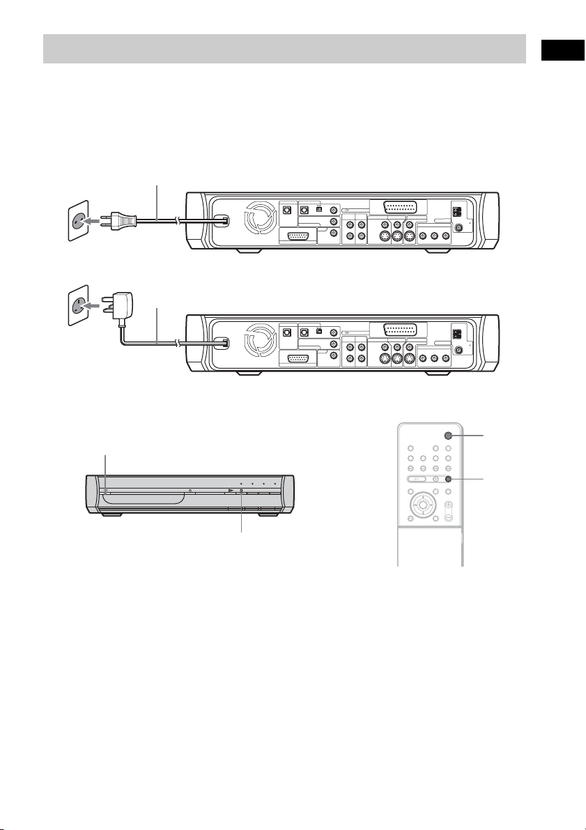
Step 5: Connecting the AC Power Cord (Mains Lead)
Before connecting the AC power cord (mains lead) of this system to a wall outlet (mains), connect the
speakers to the system (page 16).
Connect the AC power cord (mains lead) to a wall outlet (mains).
The AC plug in the illustration is European & Russian models.
AC power cord (mains lead)
VIDEO 1 / SAT 1
DIGITAL OUT
OPTICAL
The AC plug adaptor in the illustration is UK model.
AC power cord (mains lead)
DIGITAL OUT
COAXIAL
DIGITAL IN
DIGITAL IN
COAXAL
OPTICAL
VIDEO 2 / SAT 2
TV
SPEAKER
VIDEO 1 / SAT 1
OPTICAL
COAXIAL
DIGITAL IN
DIGITAL IN
COAXAL
OPTICAL
VIDEO 2 / SAT 2
TV
SPEAKER
DIGITAL IN
COAXIAL
DIGITAL IN
COAXIAL
)
OUTPUT(TO TV
VIDEO 1 /
VIDEO 2 /
VIDEO 1 / SAT 1 VIDEO 2 / SAT 2
VIDEO IN
S-VIDEO IN
VIDEO 1 / SAT 1 VIDEO 2 / SAT 2
VIDEO IN
S-VIDEO IN
S-VIDEO
S-VIDEO
MONITOR OUT
VIDEO
MONITOR OUT
VIDEO
COMPONENT VIDEO OUT
COMPONENT VIDEO OUT
SAT 1
SAT 2
L
R
AUDIO INAUDIO IN
)
OUTPUT(TO TV
VIDEO 1 /
VIDEO 2 /
SAT 1
SAT 2
L
R
AUDIO INAUDIO IN
YPB/CBPR/C
YPB/CBPR/C
ANTENNA
ANTENNA
AM
FM
75
COAXIAL
R
AM
FM
75
COAXIAL
R
Getting Started
"/1
"/1
x
x
To turn on the system
Press "/1.
To turn off the system
Press "/1. The system enters standby mode.
While playing a disc, do not turn off the system by pressing "/1. Doing so may cancel the menu
settings. When you turn off the system, first press x to stop playback and then press "/1.
29
GB
Page 30

Step 6: Performing the Quick Setup
There are a minimum number of basic adjustments available for using the system.
You can set the display language, sound track, or screen settings that match your TV type, etc.
"/1
./>
X/x
ENTER
Note
• The selectable language is
different depending on the area.
• Make sure that the function is set
to “DVD.”
To skip an adjustment, press >. To return to the previous
adjustment, press ..
1 Turn on the TV.
2 Press [/1.
3 Switch the input selector on your TV so that the signal
from the system appears on the TV screen.
[Press [ENTER] to run QUICK SETUP.] appears at the bottom
of the screen. If this message does not appear, display the
Quick Setup and perform again (page 32).
4 Press ENTER without inserting a disc.
The Setup Display for selecting the language used in the onscreen display appears.
LANGUAGE SETUP
OSD:
MENU:
AUDIO:
SUBTITLE:
ENGLISH
ENGLISH
FRANÇAIS
DEUTSCH
ITALIANO
ESPAÑOL
NEDERLANDS
DANSK
SVENSKA
5 Press X/x to select a language.
The system displays the menu and subtitles in the selected
language.
30
GB
Page 31
6 Press ENTER.
The Setup Display for selecting the aspect ratio of the TV to be
connected appears.
Getting Started
SCREEN SETUP
TV TYPE:
SCREEN SAVER:
BACKGROUND:
LINE:
4:3 OUTPUT:
7
Press X/x to select the setting that matches your TV type.
4:3 LETTER BOX
16:9
16:9
4:3 PAN SCAN
FULL
x If you have a wide-screen TV or a 4:3 standard TV with
a wide-screen mode
[16:9] (page 81)
x If you have a 4:3 standard TV
[4:3 LETTER BOX] or [4:3 PAN SCAN] (page 81)
8 Press ENTER.
The Setup Display for selecting the output method for video
signals from the EURO AV T OUTPUT (TO TV) jack on the
rear panel of the system appears.
SCREEN SETUP
TV TYPE:
SCREEN SAVER:
BACKGROUND:
LINE:
4:3 OUTPUT:
JACKET PICTURE
16:9
ON
VIDEO
VIDEO
RGB
9 Press X/x to select the output method for video signals.
• [VIDEO]: outputs video signals.
• [RGB]: outputs RGB signals.
Note
• If your TV does not accept RGB signals, no picture appears on the TV
screen even if you select [RGB]. Refer to the instructions supplied
with your TV.
10Press ENTER.
Quick Setup is finished. All connections and setup operations
are complete.
continued
31
GB
Page 32

To quit the Quick Setup
Press DISPLAY in any Step.
To recall the Quick Setup display
1 Press DISPLAY. (If a disc is playing, press x to stop
playback, then press DISPLAY.)
The Control Menu appears.
2 Press X/x to select [SETUP], then press ENTER.
The options for [SETUP] appear.
)
1 2 ( 2 7
)
BNR
1 8 ( 3 4
: :
QUICK
QUICK
CUSTOM
RESET
DVD VIDEO
3 Press X/x to select [QUICK], then press ENTER.
The Quick Setup display appears.
32
GB
Page 33

Step 7: Installing the Speakers
S
For the best possible front surround sound, use the Setup Disc and position the speakers as illustrated
below.
ide view
0.6 m ~
Front speaker (L)
Top view
TV
FOCUS SURROUND area
WIDE SURROUND area
Subwoofer
Front speaker (R)
Getting Started
Tip
• When checking the front surround
sound effect, make sure the
SOUND FIELD setting is set to
FOCUS SURROUND, and one or
two people are in the listening
position.
Positioning the speakers
The effective area of surround sound will vary depending on the
sound field selection (FOCUS SURROUND or WIDE
SURROUND). You can change the sound field setting for optimal
front surround sound effect.
For details, see “Enjoying Front Surround Sound Using Sound
Field” (page 38).
Notes about positioning the front speakers
For best results, observe the following:
– Place both front speakers the same distance apart as they are from
the listening position (to form an equilateral triangle).
– The front speakers should be placed at least 0.6 m apart.
– The front speakers should be placed at ear level in the listening
position.
– Place the front speakers forward of the TV. Make sure there are
no reflecting obstacles in front of the speakers.
continued
33
GB
Page 34

Tip
• You can attach the front speaker to
the speaker stand (optional).
WS-FVX1
– Both front speakers should be pointed straight forward. Do not
place the speakers at an angle.
Correct
Incorrect
– Do not leave a space in front of the front speakers when placed
on a table or rack, etc., as reflection may occur.
Side view
Correct
Incorrect
Using the Setup Disc
After positioning the speakers, use the supplied Setup Disc to check
the front surround sound effect.
N
Disc tray
Z
x
34
H
C/c
ENTER
GB
x
Page 35

Note
• Even if an option is selected, the
sound volume of the subwoofer
may be low. This is by default
setting, and is not a malfunction.
• If there is no sound from the
speakers, check the speaker
connection.
1 Press Z on the system.
2 Load the Setup Disc.
Place the Setup Disc on the tray, and then press Z on the
system.
The Setup Disc menu appears.
DAV-X1 / DAR-X1 Series
This setup disc is common for DAV-X1/DAR-X1 series.
3 Sit in the listening position, then select one of the three
options on the screen using
ENTER.
The selected option starts.
C/c, and press H or
Getting Started
C
FL FR
SW
RL RR
4 Listening carefully to how the option sounds to
determine the optimal surround sound effect.
If a satisfactory surround sound effect cannot be achieved,
adjust the speaker positions.
5 Press x to stop the disc.
6 Press Z on the system to eject the disc.
To adjust the volume of all the speakers at one
time
Press VOLUME +/− on the system, or press VOLUME +/− on the
remote.
35
GB
Page 36

Basic Operations
Playing Discs
"/1
Disc tray
Note
• Do not forcibly press the disc tray
closed with your finger, as this
may cause malfunction.
• Do not place more than one disc on
the tray.
Z
x
VOLUME −/+
N
FUNCTION
./>
H
ALBUM –/+
With cover opened.
"/1
FUNCTION
X
x
MUTING
VOLUME +/–
Depending on the DVD VIDEO or VIDEO CD, some operations
may be different or restricted.
Refer to the operation details supplied with your disc.
1 Turn on your TV.
2 Switch the input selector on the TV to this system.
3 Press "/1.
The system turns on.
Unless the system is set to “DVD,” press FUNCTION to select
“DVD.”
4 Press Z on the system.
5 Load a disc.
Place one disc on the tray, and then press Z on the system.
/
36
When you play an 8 cm disc, place it on the
inner circle of the tray. Be careful that the disc
is not skewed on the inner circle of the tray.
GB
Page 37

6 Press H.
The system starts playback (continuous play).
Adjust the volume.
To save the power in standby mode
Press "/1 while the system turns on. To cancel standby mode, press
"/1 once.
Additional operations
To Press
Stop x
Pause X
Resume play after pause X or H
Go to the next chapter,
track, or scene
Go back to the preceding
chapter, track, or scene
Mute the sound MUTING. To cancel muting, press it again
Stop play and remove the
disc
Replay the previous scene*
Briefly fast forward the
current scene*
Go to the next or previous
album*
2
3
> (except for JPEG)
. (except for JPEG)
or VOLUME + to adjust the sound volume.
Z
1
(instant replay) during playback.
(instant advance) during playback.
ALBUM + or – during playback.
Basic Operations
*1 DVD VIDEOs/DVD-RWs/DVD-Rs only. The button can be used except
for DivX video files.
*2 DVD VIDEOs/DVD-RWs/DVD-Rs/DVD+RWs only. The button can be
used except for DivX video files.
*3 DATA CDs/DATA DVDs only.
37
GB
Page 38

System Sound Feature
Sound Field indicator
SOUND
FIELD
C/X/x/c
ENTER
With cover opened.
FUNCTION
AMP MENU
This system can create 5.1 channel surround sound from two front
speakers and a subwoofer. You can take advantage of this front
surround sound simply by selecting one of system's
preprogrammed sound fields. They bring the exciting and powerful
sound of movie theaters into your home.
Enjoying Front Surround Sound Using
Sound Field
Press SOUND FIELD.
The present sound field appears in the front panel display.
Press SOUND FIELD repeatedly until the sound field you want
appears in the front panel display. The selected Sound Field
indicator on the front panel lights up*.
You can also select the sound field by pressing
C/X/x/c.
* When you press SOUND FIELD and the selected field is AUTO, AUTO
and the selected sound field indicator (FOCUS SURROUND, WIDE
SURROUND, or 2CH STEREO) light up.
38
GB
Page 39

Note
• When the system receives DVD
multi-channel signals or Dolby
Digital multiplex broadcast
signals, the default AUTO setting
is FOCUS SURROUND. (You
can change the AUTO setting to
WIDE SURROUND in AMP
MENU.)
• When the system receives CDs or
DATA CDs, the AUTO setting is
2CH STEREO.
• The sound field for Super Audio
CDs is 2CH STEREO only.
• The surround effect might be
difficult to hear depending on the
type of source signals (e.g., digital
stereo signals, digital multi
signals, etc.) except for DVD
multi-channel signals.
Tip
• The system memorizes the last
sound field selected for each
function mode.
Whenever you select a function
such as DVD or TUNER, the
sound field that was last applied to
function is automatically applied
again.
• If the AC power cord (mains lead)
is disconnected for a lo ng period of
time, the system may return to its
default settings.
Available sound fields
Sound field Display
AUTO AUTO MODE
FOCUS SURROUND FOCUS SURR
WIDE SURROUND WIDE SURR
2CH STEREO 2CH STEREO
* Using S-Force PRO Front Surround technology.
*
*
About S-Force PRO Front Surround
Sony’s long-term involvement in surround technology (and the vast
amounts of acoustic data accumulated as a result) has led to the
development of all-new processing method and advanced DSP to
handle this task effectively, which we call S-Force PRO Front
Surround. Compared with previous front surround technologies,
S-Force PRO Front Surround reproduces a more convincing sense
of distance and space, resulting in a true surround sound experience
without the need for rear speakers.
Automatic sound field selection
x AUTO
This mode selects the sound field (Surround mode (FOCUS
SURROUND or WIDE SURROUND) or 2CH STEREO)
automatically, according to the type of audio signal being input.
The default AUTO setting is FOCUS SURROUND.
To set the Surround mode setting (FOCUS SURROUND or WIDE
SURROUND) in AUTO MODE, follow the steps below:
1 Press AMP MENU.
2 Press X/x to select [AUTO MODE], then press ENTER or c.
3 Press X/x to select [FOCUS SURR] or [WIDE SURR], then
press ENTER.
Enjoying the Front Surround Sound System
You can enjoy two types of front surround sound, FOCUS
SURROUND or WIDE SURROUND, depending on the listening
area.
x FOCUS SURROUND
You can enjoy surround sound in a more focused sound area.
Basic Operations
continued
39
GB
Page 40

x WIDE SURROUND
You can enjoy surround sound in a wider sound area. This mode
produces less surround effect than FOCUS SURROUND.
Top view
Front speaker (L)
FOCUS SURROUND area
WIDE SURROUND area
TV
Subwoofer
Front speaker (R)
2 channel source output
x 2 CH STEREO
This mode outputs 2 channel sound regardless of the audio signal
type being input.
Note
• When you use both the VIDEO 1/
SAT 1 or VIDEO 2/SAT 2 jacks
(analog connection) and
COAXIAL DIGITAL IN or
OPTICAL DIGITAL IN jack
(digital connection) at the same
time, the digital connection takes
priority.
GB
40
Enjoying TV or VCR Sound with Front
Surround Sound
You can enjoy TV or VCR sound with the front surround sound of
this system.
For details, see “Step 3: TV Hookup” (page 20) and “Step 4: Other
Component Hookup” (page 26).
1 Press FUNCTION repeatedly until “TV,” “VIDEO1(2),” or
“SAT1(2)” (depending on what you set in the AMP
MENU, see page 73) appears in the front panel display.
2 Press SOUND FIELD repeatedly until the sound field you
want appears in the front panel display.
When you use a digital connection (COAXIAL or OPTICAL)
and the selected sound field is AUTO, you can enjoy multichannel signals with the front surround sound (default setting
is FOCUS SURROUND). Even when you use a digital
connection and the selected sound field is AUTO (FOCUS
SURROUND), if the system receives 2-channel signal, the
system will still only output 2-channel sound.
When you use an analogue connection and the selected sound
field is AUTO, the system outputs 2-channel stereo signals.
Page 41

Enjoying Discs
Resuming Playback From the Point Where You Stopped the Disc
(Resume Play)
When you stop the disc, the system remembers
the point where you pressed x and you can start
playback from the point you stopped the disc.
H
x
1 While playing a disc, press x to stop
playback.
“Resume” appears in the front panel
display, so you can restart the disc from the
point where you stopped the disc.
If “Resume” does not appear, Resume Play
is not available.
2 Press H.
The system starts playback from the point where
you stopped the disc in step 1.
To enjoy a disc that is played
before by resume playback
(Multi-disc Resume)
(DVD VIDEO, VIDEO CD only)
This system stores the point where you stopped
the disc for up to 40 discs and resumes playback
the next time you insert the same disc. If you
store a resume playback point for the 41st disc,
the resume playback point for the first disc is
deleted.
To activate this function, set [MULTI-DISC
RESUME] in [CUSTOM SETUP] to [ON]. For
details, see “[MULTI-DISC RESUME] (DVD
VIDEO/VIDEO CD only)” (page 83).
Note
• If [MULTI-DISC RESUME] in [CUSTOM SETUP]
is set to [OFF] (page 83), the resume point is cleared
when you change the function by pressing
FUNCTION.
• The point where you stopped playing may be cleared
when:
– you change the play mode.
– you change the settings on the Setup Display.
– you change the function by pressing FUNCTION.
– you disconnect the AC power cor d (mains lead) for
a long period of time.
• For DVD-RWs in VR mode, CDs, Super Audio CDs,
DATA CDs, and DATA DVDs the system
remembers the resume playback point for the current
disc. The resume point is cleared when:
– you eject the disc.
– the system enters standby mode (DATA CD/
DATA DVD only).
• Resume Play does not work during Program Play and
Shuffle Play.
• This function may not work with some discs.
• Depending on where you stop the disc, the system
may not resume playback from exactly the same
point.
• If [MULTI-DISC RESUME] in [CUSTOM SETUP]
is set to [ON] (page 83) and you playback a recorded
disc such as DVD-RW, the system may playback
other recorded discs from the same resume point.
Tip
• To play from the be ginning of the disc, press x twice,
then press H.
Enjoying Discs
41
GB
Page 42

Creating Your Own Program
(Program Play)
You can play the contents of a disc in the order
you want by arranging the order of the tracks on
the disc to create your own program. You can
program up to 99 tracks.
H
3 Press X/x to select [SET t], then
press ENTER.
[TRACK] is displayed when you play a
VIDEO CD, Super Audio CD, or CD.
PROGRAM
ALL CLEAR
1. TRACK
– –
2. TRACK
– –
3. TRACK
– –
4. TRACK
– –
5. TRACK
– –
6. TRACK
– –
7. TRACK
Tracks recorded
on a disc
0:00:00
T
– –
01
02
03
04
05
06
Total time of the
programmed tracks
4 Press c.
The cursor moves to the track row [T] (in
this case, [01]).
X/x/c
ENTER
1 Press DISPLAY.
The Control Menu appears.
2 Press X/x to select
[PROGRAM], then press ENTER.
The options for [PROGRAM] appear.
T
OFF
OFF
SET
ON
6 (14)
2 : 5 0
PLAY
CD
DISPLAY
PROGRAM
ALL CLEAR
1. TRACK
2. TRACK
3. TRACK
4. TRACK
5. TRACK
6. TRACK
7. TRACK
– –
– –
– –
– –
– –
– –
– –
0:00:00
T
– –
01
02
03
04
05
06
5 Select the track you want to program.
For example, select track [02].
Press X/x to select [02] under [T], then
press ENTER. The track number may be
displayed in 3 digits for a Super Audio CD.
Selected track
– –
– –
– –
– –
– –
– –
0:15:30
T
– –
01
02
03
04
05
06
PROGRAM
ALL CLEAR
1. TRACK 0 2
2. TRACK
3. TRACK
4. TRACK
5. TRACK
6. TRACK
7. TRACK
Total time of the programmed tracks
6 To program other tracks, repeat steps 4
to 5.
The programmed tracks are displayed in the
selected order.
42
GB
Page 43

7 Press H to start Program Play.
Program Play starts.
“PGM” appears in the front panel display.
When the program ends, you can restart the
same program again by pressing H.
To return to normal play
Pr es s CLEAR, or select [O FF ] in St ep 2. To pl ay
the same program again, select [ON] in Step 3
and press ENTER.
To turn off the Control Menu
Press DISPLAY repeatedly until the Control
Menu is turned off.
To change or cancel a program
1 Follow steps 1 to 3 of “Creating Your Own
Program.”
2 Select the program number of the track you
want to change or cancel using X/x.
If you want to delete the track from the
program, press CLEAR.
3 Follow Step 5 for new programming. To
cancel a program, select [--] under [T], then
press ENTER.
To cancel all of the tracks in the
programmed order
1 Follow steps 1 to 3 of “Creating Your Own
Program.”
2 Press X and select [ALL CLEAR].
3 Press ENTER.
Playing in Random Order
(Shuffle Play)
You can have the system “shuffle” tracks.
Subsequent “shuffling” may produce a different
playing order.
X/x
ENTER
DISPLAY
1 Press DISPLAY during playback.
The Control Menu appears.
2 Press X/x to select [SHUFFLE],
then press ENTER.
The options for [SHUFFLE] appear.
T
OFF
OFF
TRACK
6 (14)
2 : 5 0
PLAY
CD
Enjoying Discs
3 Press X/x to select the item to be
shuffled.
x When playing a VIDEO CD, Super
Audio CD, or CD
• [TRACK]: shuffles tracks on the disc.
x When Program Play is activated
• [ON]: shuffles tracks selected in Program
Play.
4 Press ENTER.
Shuffle Play starts.
“SHUF” appears in the front panel display.
continued
43
GB
Page 44

To return to normal play
Press CLEAR, or select [OFF] in Step 2.
To turn off the Control Menu
Press DISPLAY repeatedly until the Control
Menu is turned off.
Tip
• You can set Shuffle Play while the system is stopped.
Playing Repeatedly
(Repeat Play)
You can play all of the titles, tracks or albums on
a disc or a single title, chapter, track, or album
repeatedly.
You can use a combination of Shuffle or
Program Play modes.
X/x
ENTER
With cover opened.
DISPLAY
REPEAT
44
1 Press DISPLAY during playback.
The Control Menu appears.
2 Press X/x to select [REPEAT],
then press ENTER.
The options for [REPEAT] appear.
T
OFF
OFF
DISC
TRACK
6 (14)
2 : 5 0
PLAY
CD
3 Press X/x to select the item to be
repeated.
The default setting is underlined.
x When playing a DVD VIDEO or DVDRW
•[OFF]: does not play repeatedly.
• [DISC]: repeats all of the titles on the disc.
GB
Page 45

• [TITLE]: repeats the current title on a
disc.
• [CHAPTER]: repeats the current chapter.
x When playing a VIDEO CD, Super
Audio CD, or CD
• [OFF]: does not play repeatedly.
• [DISC]: repeats all of the tracks on the
disc.
• [TRACK]: repeats the current track.
x When playing a DATA CD or DATA
DVD
• [OFF]: does not play repeatedly.
• [DISC]: repeats all of the albums on the
disc.
• [ALBUM]: repeats the current album.
• [TRACK] (MP3 audio tracks only):
repeats the current track.
• [FILE] (DivX video files only): repeats
the current file.
4 Press ENTER.
The item is selected.
To return to normal play, press CLEAR, or
select [OFF] in Step 2.
To turn off the Control Menu
Press DISPLAY repeatedly until the Control
Menu is turned off.
Note
• When [MODE (MP3, JPEG)] is set to [IMAGE
(JPEG)] (page 51), you cannot select [TRACK].
Tip
• You can also press REPEAT on the remote to set
repeat play.
• Depending on the repeat type you set, indication in
the front panel display may differ:
– “REP”: Repeat all titles, tracks, or albums on a
disc.
– “REP1”: Repeat single title, chapter or album on a
disc.
Using the DVD’s Menu
A DVD is divided into a lot of sections, which
make up a picture or music feature. These
sections are called “titles.” When you play a
DVD which contains several titles, you can
select the title you want using TOP MENU.
When you play DVDs that allow you to select
items such as the language for the subtitles and
the language for the sound, select these items
using MENU.
TOP
MENU
C/X/x/c
ENTER
Number
buttons
With cover opened.
MENU
1 Press TOP MENU or MENU.
The disc’s menu appears on the TV screen.
The contents of the menu vary from disc to
disc.
2 Press C/X/x/c or the number buttons to
select the item you want to play or
change.
3 Press ENTER.
Enjoying Discs
45
GB
Page 46

Selecting [ORIGINAL] or
Selecting a Playback layer
[PLAY LIST] on a DVD-RW
Some DVD-RWs in VR (Video Recording)
mode have two types of titles for playback:
originally recorded titles ([ORIGINAL]) and
titles that can be created on recordable DVD
players for editing ([PLAY LIST]). You can
select the type of title to be played.
x
X/x
ENTER
DISPLAY
1 Press DISPLAY. (If a disc is playing,
press x to stop playback, then press
DISPLAY.)
The Control Menu appears.
2 Press X/x to select [ORIGINAL/
PLAY LIST], then press ENTER.
The options for [ORIGINAL/PLAY LIST]
appear.
)
1 ( 4 4
(
3
2 8
T
1 : 3 0 : 5 0
PLAY LIST
PLAY LIST
ORIGINAL
)
DVD-RW
for a Super Audio CD
Some Super Audio CDs consist of a Super
Audio CD layer and a CD layer. You can select
the playback layer you want to listen to.
x
SA-CD/CD
With cover opened.
Press SA-CD/CD. (If a disc is playing, press
x to stop playback, then press SA-CD/CD.)
Each time you press the button, a Super Audio
CD layer or a CD layer is alternately selected.
When playing a Super Audio CD layer,
“SA-CD” lights up in the front panel display.
Note
• For details about Super Audio CD discs, see page 8.
• Each play mode function works only within the
selected layer.
• You cannot change a playback layer during playback.
3 Press X/x to select a setting.
• [PLAY LIST]: plays the titles created
from [ORIGINAL] for editing.
• [ORIGINAL]: plays the titles originally
recorded.
4 Press ENTER.
GB
46
Page 47

Playing VIDEO CDs with PBC Functions (Ver.2.0)
(PBC Playback)
With PBC (Playback Control) functions, you
can enjoy simple interactive operations, search
functions, and other such operations.
PBC playback allows you to play VIDEO CDs
interactively by following the menu on the TV
screen.
ENTER
Number
buttons
• Depending on the VIDEO CD, [Press ENTER] in
Step 3 may appear as [Press SELECT] in the
instructions supplied with the disc. In this case, press
H.
Tip
• To play without using PBC, press ./> or the
number buttons while the system is stopped to select
a track, then press H or ENTER.
You cannot play still pictures such as a menu. To
return to PBC playback, press x twice, then press
H.
Enjoying Discs
With cover opened.
1 Start playing a VIDEO CD with PBC
functions.
The menu for your selection appears.
2 Select the item number you want by the
number buttons.
3 Press ENTER.
4 Follow the instructions in the menu for
interactive operations.
Refer to the operation details supplied with
the disc, as the operating procedure may
differ depending on the VIDEO CD.
To go back to the menu
Press O RETURN.
Note
• You cannot use Program Play, Shuffle Play, or
Repeat Play with Video CDs and Super VCDs with
PBC playback.
47
GB
Page 48

About MP3 Audio Tracks and JPEG Image Files
What is MP3/JPEG?
MP3 is audio compression technology that
satisfies the ISO/MPEG regulations. JPEG is
image compression technology.
* “Design rule for Camera File system”: Image
standards for digital cameras regulated by Japan
Electronics and Information Technology Industries
Association (JEITA).
Note
• The system will play any data with the extension
“.MP3,” “.JPG,” or “.JPEG” even if they are not in
MP3 or JPEG format. Playing this data may generate
a loud noise which could damage your speaker
system.
• The system does not conform to audio in MP3PRO
format.
Discs that the system can
play
You can play back DATA CDs (CD-ROMs/CDRs/CD-RWs) recorded in MP3 (MPEG1 Audio
Layer 3) and JPEG format. However, the discs
must be recorded according to ISO 9660 Level
1, Level 2 or Joliet format for the system to
recognize the tracks (or files). You can also play
discs recorded in Multi Session.
See the instructions supplied with the CD-R/
CD-RW drives and the recording software (not
supplied) for details on the recording format.
About the multi-session disc
If MP3 audio tracks or JPEG image files are
recorded in the first session, the system will also
play MP3 audio tracks or JPEG image files in
other sessions. If audio tracks and images in
audio CD format or video CD format are
recorded in the first session, only the first
session will be played back.
Note
• The system may not be able to play some DATA
CDs. In this case, you cannot view the JPEG images
recorded.
Playback order of MP3 audio
tracks or JPEG image files
The playback order of MP3 audio tracks or
JPEG image files recorded on a DATA CD is as
follows:
x Structure of disc contents
Tree 1 Tree 2 Tree 3 Tree 4 Tree 5
ROOT
MP3 audio track or JPEG
image file that the system can
play
The system can play the MP3 audio tracks or
JPEG image files:
• which have the extension “.MP3” (MP3 audio
track) or “.JPG”/“.JPEG” (JPEG image file)
• which conform to the DCF* image file format
GB
48
Track (MP3 audio) or
Album
File (JPEG image)
When you insert a DATA CD and press H, the
numbered tracks (or files) are played
sequentially, from 1 through 7. Any subalbums/tracks (or files) contained within a
currently selected album take priority over the
Page 49

next album in the same tree. (Example: C
contains D so 4 is played before 5.)
Playing DATA CDs with
When you press MENU and the list of album
names appears (page 48), the album names are
arranged in alphabetical order (A t B t C
t D t F t G). Albums that do not contain
tracks (or files) (such as album E) do not appear
in the list.
Tip
• If you add number s (01, 02, 03, etc.) to the front of the
track/file names when you store the tracks (or files) in
a disc, the tracks and files will be played in that order.
• If a disc consists of many trees, it takes longer to start
playback.
Note
• Playback order may differ from the illustration
depending on the software you use to create the
DATA CD, or if there are more than 200 albums and
300 files in each album.
• The system can recognize up to 200 albums, and will
not play any albums beyond the 200th.
• The system may take longer time to playback, when
progressing to the following album or jump to other
album.
• Some type of JPEG files cannot be played.
MP3 Audio Track and
JPEG Image Files
MP3 audio tracks and JPEG image files
recorded on DATA CDs (CD-ROMs/CD-Rs/
CD-RWs) can be played on this system.
./>
H
C/X/x/c
ENTER
O RETURN
CLEAR
With cover opened.
Selecting an album
x
MENU
PICTURE
NAVI
Enjoying Discs
1 Load a DATA CD.
The system starts playing from the first
album.
2 Press MENU.
The list of albums recorded on the DATA
CD appears. When an album is being
played, its title is shaded.
You can turn the album list on and off by
pressing MENU.
(
3 0
)
5
BOSSA NOVA
CLASSIC
JAZZ
KARAOKE
MY FAVOURITE SONG
R&B
ROCK BEST HIT
SALSA OF CUBA
continued
49
GB
Page 50

3 Press X/x to select the album you want
and press H.
The system starts playing the selected
album.
To stop playback
Press x.
To play the next or previous
MP3 audio track
Press ./>. Note that you can select
the next album by continuing to press >
after the last track on the first album, but
that you cannot return to the previous album
by pressing .. To return to the previous
album, select the album from the album list.
To play the next or previous
JPEG image file
Press C/c when the Control Menu is not
displayed. Note that you can select the next
album by continuing to press c after the last
image on the first album, but that you
cannot return to the previous album by
pressing C. To return to the previous album,
select the album from the album list.
To turn off the display
Press MENU.
Selecting an MP3 audio track
1 Load a DATA CD.
The system starts playing from the first
album.
2 Press MENU.
The albums recorded on the DATA CD
appear. When an album is being played, its
title is shaded.
3 Press X/x to select an album and press
ENTER.
The list of tracks contained in the album
appears.
4 Press X/x to select a track and press
ENTER.
The selected track starts playing. You can
turn the track list off by pressing MENU.
Pressing MENU again will display the
album list.
To stop playback
Press x.
To play the next or previous
MP3 audio track
Press ./>. Note that you can select
the next album by continuing to press >
after the last track on the first album, but
that you cannot return to the previous album
by pressing .. To return to the previous
album, select the album from the album list.
To return to the previous
display
Press O RETURN.
To turn off the display
Press MENU.
Selecting a JPEG image file
1 Load a DATA CD.
The system starts playing from the first
album.
2 Press MENU.
The albums recorded on the DATA CD
appear. When an album is being played, its
title is shaded.
3 Press X/x to select an album and press
PICTURE NAVI.
Images of files in the album appear in 16
subscreens.
50
M Y FAVOURITE SONG
1 ( 2 5 6
ALL BLUES
AUTUM LEAVES
MILES TONES
MY FUNNY VALENTINE
MY ROMANCE
SOMEDAY MY PRINCE W...
WALTZ FOR DEBBY
GB
)
1234
5678
9101112
13 14 15 16
Page 51

4 Press C/X/x/c to select the image you
want to view and press ENTER.
To play the next or previous
JPEG image file
Press C/c when the Control Menu is not
displayed. Note that you can select the next
album by continuing to press c after the last
image on the first album, but that you
cannot return to the previous album by
pressing C. To return to the previous album,
select the album from the album list.
To rotate a JPEG image
When a JPEG image file is displayed on the
screen, you can rotate the image by 90
degrees.
Press X/x while viewing an image. Each
time you press X, the image rotates
counterclockwise by 90 degrees.
Example of when you press X once:
Rotating direction
Playing Audio Tracks and Images as a Slide Show with Sound
You can play a slide show with sound by first
placing both MP3 and JPEG files in the same
album on a DATA CD. When you play back the
DATA CD, select [AUTO] mode as explained
below.
H
X/x
ENTER
x
MENU
DISPLAY
1 Load a DATA CD.
The system starts playing from the first
album.
2 Press x.
The system stops playback.
3 Press DISPLAY.
The Control Menu appears.
Enjoying Discs
Press CLEAR to return to normal view.
To stop playback
Press x.
4 Press X/x to select [MODE
(MP3, JPEG)], then press ENTER.
The options for [MODE (MP3, JPEG)]
appear.
)
1 2 ( 2 7
)
1 8 ( 3 4
T
1 : 3 2 : 5 5
AUTO
AUTO
AUDIO (MP3)
IMAGE (JPEG)
DATA CD
MP3
5 Press X/x to select the setting you
want and press ENTER.
continued
51
GB
Page 52

The default setting is underlined.
•[AUTO]
: plays both the JPEG image files
and MP3 audio tracks in the same album
as a slide show.
• [AUDIO (MP3)]: plays only MP3 audio
tracks continuously.
• [IMAGE (JPEG)]: plays only JPEG
image files as a slide show.
6 Press MENU.
The list of albums recorded on the DATA
CD appears.
7 Press X/x to select the album you want
and press H.
The system starts playing the selected
album.
You can turn the album list on and off by
pressing MENU repeatedly.
Tip
• When you select [AUTO], the system can recognize
up to 300 MP3 tracks and 300 JPEG files in a single
album. When you select [AUDIO (MP3)] or [IMAGE
(JPEG)], the system can recognize up to 600 MP3 and
600 JPEG files in a single album. A maximum of 200
albums can be recognized regardless of the selected
mode.
Note
• You cannot playback JPEG files and MP3 tracks at
the same time if they are not contained in the same
album.
• PICTURE NAVI does not work when [AUDIO
(MP3)] is selected.
• If you play large MP3 track data and JPEG image
data at the same time, the sound may skip. It is
recommended that you set the MP3 bit rate to 128
kbps or lower when creating the file. If the sound still
skips, then reduce the size of the JPEG file.
Specifying the slide show
duration
(JPEG only)
When you play JPEG image files using slide
show, you can specify the duration for slides to
appear on the screen.
1 Press DISPLAY twice.
The Control Menu for JPEG appears.
2 Press X/x to select
[INTERVAL], then press ENTER.
The options for [INTERVAL] appear.
12)
3 (
4)
1(
10 / 29 / 2 004
NORMAL
NORMAL
FAST
SLOW1
SLOW2
DATA CD
JPEG
3 Press X/x to select the setting you
want.
The default setting is underlined.
• [NORMAL]
: sets the duration to about 6
to 9 seconds.
• [FAST]: sets the duration shorter than
[NORMAL].
• [SLOW1]: Sets the duration longer than
[NORMAL].
• [SLOW2]: Sets the duration longer than
[SLOW1].
4 Press ENTER.
The selected setting takes effect.
Note
• Some JPEG files may take longer to display than
others, which may make the duration seems longer
that the option you selected. Especially progressive
JPEG files or JPEG files of 3,000,000 pixels or more.
Selecting an effect for image
files in the slide show
(JPEG only)
When you play a JPEG image file, you can
select the effect to be used when viewing the
slide show.
1 Press DISPLAY twice.
The Control Menu for JPEG appears.
2 Press X/x to select [EFFECT],
then press ENTER.
The options for [EFFECT] appear.
52
GB
Page 53

12)
3 (
4)
1(
1 0 / 2 3 / 2 0 0 4
MODE1
MODE1
MODE2
MODE3
MODE4
MODE5
OFF
DATA CD
JPEG
3 Press X/x to select the setting you
want.
The default setting is underlined.
• [MODE1]
: The image sweeps in from top
to bottom.
• [MODE2]: The image stretches out from
left to right of the screen.
• [MODE3]: The image stretches out from
the center of the screen.
• [MODE4]: The images randomly cycle
through the effects.
• [MODE5]: The next image slides over the
previous image.
• [OFF]: Turns off this function.
4 Press ENTER.
The selected setting takes effect.
Enjoying DivX® Videos
./>
H
C/X/x/c
ENTER
O RETURN
About DivX Video Files
DivX® is a video file compression technology,
developed by DivXNetworks, Inc. This product
is an official DivX
You can play DATA CDs and DATA DVDs that
contain DivX
DATA CDs and DATA DVDs that
the system can play
Playback of DATA CDs (CD-ROMs/CD-Rs/
CD-RWs) and DATA DVDs (DVD-Rs/DVDRWs/DVD+Rs/DVD+RWs) on this system is
subject to certain conditions:
– With DATA CDs that contain DivX video
files in addition to MP3 audio tracks or JPEG
image files, the system plays only the DivX
video files.
– With DATA DVDs, the system plays DivX
video files only. Any data other than DivX
video file, such as MP3 audio tracks and
JPEG image files, are not played.
However, this system only plays DATA CDs
whose logical format is ISO 9660 Level 1/Level
2 or Joliet, and DATA DVDs of Universal Disk
Format (UDF).
You can also play DATA CDs recorded in Multi
Session (page 48), although DATA DVDs
recorded in Multi Session are not playable.
Refer to the instructions supplied with the disc
drives and the recording software (not supplied)
for details on the recording format.
®
Certified product.
®
video files.
x
MENU
Enjoying Discs
continued
53
GB
Page 54

About playback order of data on
DATA CDs or DATA DVDs
See “Playback order of MP3 audio tracks or
JPEG image files” (page 48). Note that the
playback order may not be applicable,
depending on the software used for creating the
DivX video file, or if there are more than 200
albums and 600 DivX video files in each album.
Note
• The system may not be able to play some DATA
CDs/DATA DVDs created in the Packet Write
format.
DivX video files that the system
can play
The system can play data that is recorded in
DivX format, and which has the extension
“.AVI,” or “.DIVX.” The system will not play
files with the extension “.AVI” or “.DIVX” if
they do not contain a DivX video.
Tip
• For details about playable MP3 audio tracks or JPEG
image files on DATA CDs, see “MP3 audio track or
JPEG image file that the system can play” (page 48).
Note
• The system may not play a DivX video file when the
file has been combined from two or more DivX video
files.
• The system cannot play a DivX video file of size
more than 720 (width) × 576 (height) or 2GB.
• Depending on the DivX video file, the picture may be
unclear or the sound may skip.
• The system cannot play some DivX video files that
are longer than 3 hours.
Playing DivX Video Files
You can play DivX video files on DATA CDs
(CD-ROMs/CD-Rs/CD-RWs) and DATA
DVDs (DVD-Rs/DVD-RWs/DVD+Rs/
DVD+RWs).
Tip
• You can view the disc information while playing a
DivX video file (page 60).
Note
• If there are no DivX video files recorded on a DATA
DVD, a message appears to indicate that the disc is
not playable.
• Depending on the DivX video file, the picture may
pause or be unclear. In which case, it is recommended
that you create the file at a lower bit rate. If the sound
is still noisy, MP3 is the recommended audio format.
Note, however, this system does not conform to
WMA (Windows Media Audio) format.
• Because of the compression technology used for
DivX video files, it may take some time after you
press H for the picture to appear.
• Depending on the DivX video file, the sound may not
match the pictures on the screen.
Selecting an album
1 Press MENU.
A list of albums on the disc appears. Only
albums that contain DivX video files are
listed.
( 3 )
3
SUMMER 2003
NEW YEAR'S DAY
MY FAVOURITES
2 Press X/x to select the album you want
to play.
3 Press H.
The system starts playing the selected
album.
To select DivX video files, see “Selecting a
DivX video file” (page 55).
To stop playback
Press x.
To go to the next or previous
page
Press C/c.
To turn off the display
Press MENU repeatedly.
54
GB
Page 55

Selecting a DivX video file
1 After Step 2 of “Selecting an album,”
press ENTER.
The list of files in the album appears.
Adjusting the Delay Between the Picture and Sound
M Y FAVOURITES
1 ( 2
HAWAII 2004
VENUS
)
2 Press X/x to select a file and press
ENTER.
The selected file starts playing.
To stop playback
Press x.
To go to the next or previous
page
Press C/c.
To return to the previous
display
Press O RETURN.
To play the next or previous
DivX video file without turning
on the above file list
You can select the next or previous DivX
video file in the same album by pressing
./>.
You can also select the first file of the next
album by pressing > during playback of
the last file of the current album. Note that
you cannot return to the previous album by
pressing .. To return to the previous
album, select it from the album list.
Tip
• If the number of viewing times is preset, you can play
the DivX video files as many times as the preset
number. The following occurrences are counted:
– when the system is turned off.
– when the disc tray is opened.
– when another file is played.
(A/V SYNC)
When the sound does not match the pictures on
the screen, you can adjust the delay between the
picture and sound.
X/x/c
ENTER
AMP MENU
With cover opened.
1 Press AMP MENU.
2 Press X/x repeatedly until “A/V SYNC”
appears in the front panel display, then
press ENTER or c.
3 Press X/x to select the setting.
• SYNC OFF: does not adjust.
• SYNC ON: adjusts the difference
between picture and sound.
4 Press ENTER or AMP MENU.
The AMP menu turns off.
Note
• Depending the input stream, this function may not be
effective.
• This function does not work for signals from a
connected digital satellite tuner, MP3 audio signals,
Super Audio CDs, or DTS-CDs.
Enjoying Discs
55
GB
Page 56

Searching for a Particular Point on a Disc
(Scan, Slow-motion Play, Freeze Frame)
You can quickly locate a particular point on a
disc by monitoring the picture or playing back
slowly.
m/M
H
/ SLOW
Playback direction
× 2B t 1M t 2M t 3M
3M (DVD VIDEO/DVD-RW/DivX video/VIDEO
CD only)
× 2B (DVD VIDEO/Super Audio CD/CD only)
Opposite direction
× 2b t 1m t 2m t 3m
3m (DVD VIDEO/DVD-RW/DivX video/VIDEO
CD only)
× 2b (DVD VIDEO only)
The “
× 2B”/“×2b” playback speed is about
twice the normal speed. The “3M”/“3m”
playback speed is faster than the “2M”/
“2m” and the “2M”/“2m” playback speed
is faster than “1M”/“1m.”
/
With cover opened.
Note
• Depending on the DVD/VIDEO CD, you may not be
able to do some of the operations described.
Locating a point quickly by
playing a disc in fast forward
or fast reverse (Scan)
(except for JPEG)
Press m or M while playing a disc.
When you find the point you want, press H to
return to normal speed. Each time you press
m or M during scan, the playback
speed changes. With each press the indication
changes as shown below. Actual speeds may
differ with some discs.
Watching frame by frame
(Slow-motion Play)
(DVD VIDEO, DVD-RW, DivX video,
VIDEO CD only)
Press m or M when the system is in
pause mode. To return to the normal playback
speed, press H. Each time you press m or
M during Slow-motion Play, the playback
speed changes. Two speeds are available. With
each press the indication changes as follows:
Playback direction
2 y 1
Opposite direction (DVD VIDEO/DVD-RW
only)
2 y 1
The “2 ”/“2 ” playback speed is slower
than “1 ”/“1 .”
56
GB
Page 57

Playing one frame at a time
(Freeze Frame)
(except for Super Audio CD, CD, and
JPEG)
When the system is in the pause mode, press
(step) to go to the next frame. Press
(step) to go to the preceding frame
(DVD VIDEO/DVD-RW only). To return to
normal playback, press H.
Note
• You cannot search for a still picture on a DVD-RW in
VR mode.
• For DATA CDs, this function works only for DivX
video files.
Searching for a Title/ Chapter/Track/Scene, etc.
You can search a DVD by title or chapter, and
you can search a VIDEO CD/Super Audio CD/
CD/DATA CD/DATA DVD by track, index, or
scene. As titles and tracks are assigned unique
numbers on the disc, you can select the desired
one by entering its number. Or, you can search
for a scene using the time code.
X/x
ENTER
DISPLAY
Number
buttons
Enjoying Discs
CLEAR
With cover opened.
1 Press DISPLAY. (When playing a
DATA CD with JPEG image files, press
DISPLAY twice.)
The Control Menu appears.
2 Press X/x to select the search method.
x When playing a DVD VIDEO/DVD-RW
[TITLE]
[CHAPTER]
[TIME/TEXT]
Select [TIME/TEXT] to search for a
starting point by inputting the time code.
x When playing a VIDEO CD/Super
VCD without PBC Playback
[TRACK]
continued
57
GB
Page 58

[INDEX]
x When playing a VIDEO CD/Super
VCD with PBC Playback
[SCENE]
x When playing a Super Audio CD
[TRACK]
[INDEX]
x When playing a CD
[TRACK]
x When playing a DATA CD (MP3
audio)
[ALBUM]
[TRACK]
x When playing a DATA CD (JPEG file)
[ALBUM]
[FILE]
x When playing a DivX video
[ALBUM]
[FILE]
Example: when you select
[CHAPTER]
[** (**)] is selected (** refers to a number).
The number in parentheses indicates the
total number of titles, chapters, tracks,
indexes, scenes, albums or files.
)
1 2 ( 2 7
)
1 8 ( 3 4
T
1 : 3 2 : 5 5
Selected row
DVD VIDEO
3 Press ENTER.
[** (**)] changes to [– – (**)].
)
1 2 ( 2 7
)
T
( 3 4
1 : 3 2 : 5 5
DVD VIDEO
4 Press X/x or the number buttons to
select the title, chapter, track, index,
scene, etc., number you want to search
for.
If you make a mistake
Cancel the number by pressing CLEAR,
then select another number.
5 Press ENTER.
The system starts playback from the
selected number.
To search for a scene using the
time code (DVD VIDEO/DVD-RW
only)
1 In Step 2, select [TIME/TEXT].
[T **:**:**] (playing time of the current title)
is selected.
2 Press ENTER.
[T **:**:**] changes to [T --:--:--].
3 Input the time code using the number
buttons, then press ENTER.
For example, to find the scene at 2 hours, 10
minutes, and 20 seconds after the beginning,
just enter [2:10:20].
Tip
• When the Contro l Menu display is turned off, you can
search for a chapter (DVD VIDEO/DVD-RW), track
(Super Audio CD/CD), or file (DATA CD (DivX
video)/DATA DVD) by pressing the number buttons
and ENTER.
Note
• You cannot search for a scene on a DVD+RW using
the time code.
58
GB
Page 59

Searching by Scene
(Picture Navigation)
You can divide the screen into 9 subscreens and
find the desired scene quickly.
1
4
7
2
5
8
3
6
9
4 Press C/X/x/c to select a title, chapter,
or track, and press ENTER.
Playback starts from the selected scene.
Enjoying Discs
C/X/x/c
ENTER
With cover opened.
DISPLAY
PICTURE
NAVI
1 Press PICTURE NAVI during playback.
The following display appears.
CHAPTER VIEWER
ENTER
2 Press PICTURE NAVI repeatedly to
select an item.
• [TITLE VIEWER] (DVD VIDEO only):
displays the first scene of each title.
• [CHAPTER VIEWER] (DVD VIDEO
only): displays the first scene of each
chapter.
• [TRACK VIEWER] (VIDEO CD/
Super VCD only): displays the first scene
of each track.
3 Press ENTER.
The first scene of each title, chapter, or
track appears as follows.
To return to normal play during
setting
Press O RETURN or DISPLAY.
Note
• Depending on the disc, you may not be able to select
some items.
59
GB
Page 60

Viewing Information About the Disc
DISPLAY
DISPLAY
When playing a DVD VIDEO or
DVD-RW
t Playing time and number of the current
title
r
Remaining time of the current title
r
Playing time and number of the current
chapter
r
Remaining time of the current chapter
r
Disc name
r
Title and chapter
r
The display returns to the top image after
2 seconds.
With cover opened.
Viewing the Playing Time and
Remaining Time in the Front
Panel Display
You can check disc information, such as the
remaining time, total number of titles in a DVD,
tracks in a VIDEO CD, Super Audio CD, CD, or
MP3, file name of a DivX video using the front
panel display (page 95).
Press DISPLAY.
Each time you press DISPLAY while playing
the disc, the display changes as shown in the
charts.
When playing a DATA CD (DivX
video) or DATA DVD (DivX video)
t Playing time of the current file
r
Current file name
r
Current album and file number
r
The display returns to the top image after
2 seconds.
60
GB
Page 61

When playing a VIDEO CD
(without PBC functions), Super
Audio CD, or CD
t Playing time of the current track
r
Remaining time of the current track
r
Playing time of the disc
r
Remaining time of the disc
r
Disc name
r
Track and index*
r
The display returns to the top image after
2 seconds.
* Except for CD.
When playing an MP3
t Playing time and current track number
r
Track (file) name
Note
• The system can only display the first level of the
DVD/CD text, such as the Disc name or title.
• If an MP3 file name cannot be displayed, “*” will
appear in the front panel display instead.
• The disc name or track name may not be displayed
depending on the text.
• Playing time of MP3 audio tracks and DivX video
files may not be displayed correctly.
Checking the Playing Time
and Remaining Time
You can check the playing time and remaining
time of the current title, chapter, or track, and the
total playing time or remaining time of the disc.
You can also check the DVD text and MP3
folder name/file name recorded on the disc.
1 Press DISPLAY during playback.
The following display appears.
T 1:01:57
Time information
2 Press DISPLAY repeatedly to change
the time information.
The display and the kinds of time that you
can check depend on the disc you are
playing.
x When playing a DVD VIDEO or DVDRW
• T **:**:**
Playing time of the current title
• T–**:**:**
Remaining time of the current title
• C **:**:**
Playing time of the current chapter
• C–**:**:**
Remaining time of the current chapter
x When playing a VIDEO CD (with PBC
functions)
•**:**
Playing time of the current scene
x When playing a VIDEO CD (without
PBC functions), Super Audio CD, or CD
•T **:**
Playing time of the current track
• T–**:**
Remaining time of the current track
• D **:**
Playing time of the current disc
• D–**:**
Remaining time of the current disc
x When playing a DATA CD (MP3
audio)
•T **:**
Playing time of the current track
x When playing a DATA CD (DivX
video)/DATA DVD (DivX video)
•**:**:**
Playing time of the current file
Enjoying Discs
continued
61
GB
Page 62

Note
• Only alphabetical letters and numbers can be
displayed.
• Depending on the type of disc being played, the
system can only display a limited number of
characters. Also, depending on the disc, not all text
characters will be displayed.
Checking the play information
of the Disc
To check DVD/Super Audio CD/CD
text
Press DISPLAY repeatedly in step 2 to display
text recorded on the DVD/Super Audio CD/CD.
The DVD/Super Audio CD/CD text appears
only when text is recorded in the disc. You
cannot change the text. If the disc does not
contain text, “NO TEXT” appears.
* Appears when:
– playing an MP3 audio track on DATA CDs.
– playing a DivX video file that contains MP3 audio
signals on DATA CDs/DATA DVDs.
Checking the date
information
(JPEG only)
You can check the date information during
playback when the Exif* tag is recorded in the
JPEG image data.
Press DISPLAY twice during playback.
The Control Menu appears.
)
1 ( 8
)
1 ( 2 0
01/ 01/ 2003
Date information
DATA CD
JPEG
BRAHMS SYMPHONY
To check DATA CD (MP3 audio/
DivX video)/DATA DVD (DivX
video) text
By pressing DISPLAY while playing MP3
audio tracks on a DATA CD or DivX video files
on a DATA CD/DATA DVD, you can display
the name of the album/track/file, and the audio
bit rate (the amount of data per second of the
current audio) on your TV screen.
Bit rate*
128k
17:30T
JAZZ
RIVER SIDE
Album name Track/file name
* “Exchangeable Image File Format” is a digital
camera image format defined by the Japan
Electronics and Information Technology Industries
Association (JEITA).
Tip
• Date information is [DD/MM/YYYY].
DD: Day
MM: Month
YYYY: Year
62
GB
Page 63

Using Various Additional Functions
Changing the Angles
If various angles (multi-angles) for a scene are
recorded on a DVD VIDEO, you can change the
viewing angle.
For example, while playing a scene of a train in
motion, you can display the view from either the
front of the train, the left window of the train, or
from the right window without having the train’s
movement interrupted.
ANGLE
Displaying the Subtitles
If subtitles are recorded on a disc, you can turn
the subtitles on or off while playing. If
multilingual subtitles are recorded on the disc,
you can change the subtitle language while
playing, or turn the subtitles on or off whenever
you want. You can select a language you are
learning, for example, and turn on the subtitles
for better understanding.
SUBTITLE
With cover opened.
Using Various Additional Functions
With cover opened.
Press ANGLE during playback.
Each time you press ANGLE, the angle changes.
Note
• Depending on the DVD VIDEO, you may not be able
to change the angle even if multi-angles are recorded
on the DVD VIDEO.
Press SUBTITLE during playback.
Each time you press SUBTITLE, the subtitle
language changes.
Note
• Depending on the DVD VIDEO, you may not be able
to change the subtitles even if multilingual subtitles
are recorded on it. You also may not be able to turn
them off.
• You can change the subtitles if the DivX video file
has an “.AVI” or “.DIVX” extension and contains
subtitle information within the same file.
63
GB
Page 64

Locking Discs
(CUSTOM PARENTAL CONTROL, PARENTAL CONTROL)
You can set 2 kinds of playback restrictions for
the desired disc.
• Custom Parental Control
You can set playback restrictions so that the
system will not play inappropriate discs.
• Parental Control
Playback of some DVD VIDEOs can be
limited according to a predetermined level
such as the age of the users. Scenes may be
blocked or replaced with different scenes.
The same password is used for both Custom
Parental Control and Parental Control.
x
C/X/x
ENTER
3 Press X/x to select
[PARENTAL CONTROL], then press
ENTER.
The options for [PARENTAL CONTROL]
appear.
)
1 2 ( 2 7
)
1 8 ( 3 4
T
1 : 3 2 : 5 5
OFF
ON
PLAYER
PASSWORD
DVD VIDEO
4 Press X/x to select [ON t], then press
ENTER.
x If you have not entered a password
The display for registering a new password
appears.
PARENTAL CONTROL
Enter a new 4-digit password,
ENTER
then press
.
Number
buttons
With cover opened.
Preventing playback of
specific discs [CUSTOM
PARENTAL CONTROL]
You can set the same Custom Parental Control
password for up to 40 discs. When you set the
41st-disc, the first disc is canceled.
1 Insert the disc you want to lock.
If the disc is playing, press x to stop
playback.
2 Press DISPLAY.
The Control Menu appears.
GB
64
DISPLAY
Enter a 4-digit password using the number
buttons, then press ENTER.
The display for confirming the password
appears.
x When you have already registered a
password
The display for entering the password
appears.
PARENTAL CONTROL
Enter password, then press
ENTER
.
5 Enter or re-enter your 4-digit password
using the number buttons, then press
ENTER.
[Custom parental control is set.] appears
and the screen returns to the Control Menu.
Page 65

To turn off the Custom Parental
Control function
1 Follow steps 1 through 3 of “Preventing
playback of specific discs [CUSTOM
PARENTAL CONTROL].”
2 Press X/x to select [OFF t], then press
ENTER.
3 Enter your 4-digit password using the
number buttons, then press ENTER.
To play a disc for which Custom
Parental Control is set
1 Insert the disc for which Custom Parental
Control is set.
The [CUSTOM PARENTAL CONTROL]
display appears.
CUSTOM PARENTAL CONTROL
Custom parental control is already
set. To play, enter your password
ENTER
and press
.
2 Enter your 4-digit password using the
number buttons, then press ENTER.
The system is ready for playback.
Tip
• If you forget your password, enter the 6-digit number
“199703” using the number buttons when the
[CUSTOM PARENTAL CONTROL] display asks
you for your password, then press ENTER. The
display will ask you to enter a new 4-digit password.
2 Press X/x to select
[PARENTAL CONTROL], then press
ENTER.
The options for [PARENTAL CONTROL]
appear.
)
1 2 ( 2 7
)
1 8 ( 3 4
T
1 : 3 2 : 5 5
OFF
ON
PLAYER
PASSWORD
DVD VIDEO
3 Press X/x to select [PLAYER t], then
press ENTER.
x If you have not entered a password
The display for registering a new password
appears.
PARENTAL CONTROL
Enter a new 4-digit password,
ENTER
then press
.
Enter a 4-digit password using the number
buttons, then press ENTER.
The display for confirming the password
appears.
x When you have already registered a
password
The display for entering the password
appears.
Using Various Additional Functions
Limiting playback for children
[PARENTAL CONTROL]
(DVD VIDEO only)
Playback of some DVD VIDEOs can be limited
according to a predetermined level such as the
age of the users. The [PARENTAL CONTROL]
function allows you to set a playback limitation
level.
1 Press DISPLAY. (If a disc is playing,
press x to stop playback, then press
DISPLAY.)
The Control Menu appears.
PARENTAL CONTROL
Enter password, then press
ENTER
.
continued
65
GB
Page 66

4 Enter or re-enter your 4-digit password
using the number buttons, then press
ENTER.
The display for setting the playback
limitation level appears.
PARENTAL CONTROL
LEVEL: OFF
STANDARD:
USA
5 Press X/x to select [STANDARD], then
press ENTER.
The selection items for [STANDARD] are
displayed.
PARENTAL CONTROL
LEVEL:
STANDARD:
OFF
USA
USA
OTHERS
6 Press X/x to select a geographic area
as the playback limitation level, then
press ENTER.
The area is selected.
When you select [OTHERS t], select and
enter a standard code in the table on page 67
using the number buttons.
7 Press X/x to select [LEVEL], then press
ENTER.
The selection items for [LEVEL] are
displayed.
PARENTAL CONTROL
LEVEL: OFF
STANDARD:
OFF
8:
NC17
7:
R
6:
5:
Parental Control setting is complete.
PARENTAL CONTROL
LEVEL:
STANDARD: USA
4: PG13
The lower the value, the stricter the
limitation.
To turn off the Parental Control
function
Set [LEVEL] to [OFF] in Step 8.
To play a disc for which Parental
Control is set
1 Insert the disc and press H.
The display for entering your password
appears.
2 Enter your 4-digit password using the
number buttons, then press ENTER.
The system starts playback.
Tip
• If you forget your password, remove the disc and
repeat steps 1 to 3 of “Preventing playback of specific
discs [CUSTOM PARENTAL CONTROL].” When
you are asked to enter your password, enter “199703”
using the number buttons, then press ENTER. The
display will ask you to enter a new 4-digit password.
After you enter a new 4-digit password, replace the
disc in the system and press H. When the display for
entering your password appears, enter your new
password.
Note
• When you play discs which do not have the Parental
Control function, playback cannot be limited on this
system.
• Depending on the disc, you may be asked to change
the parental control level while playing the disc. In
this case, enter your password, then change the level.
If the Resume Play mode is canceled, the level returns
to the previous level.
8 Press X/x to select the level you want,
then press ENTER.
GB
66
Page 67

Area Code
Standard Code
Argentina 2044
Australia 2047
Austria 2046
Belgium 2057
Brazil 2070
Canada 2079
Chile 2090
China 2092
Denmark 2115
Finland 2165
France 2174
Germany 2109
India 2248
Indonesia 2238
Italy 2254
Japan 2276
Korea 2304
number
Standard Code
Malaysia 2363
Mexico 2362
Netherlands 2376
New
Zealand
Norway 2379
Pakistan 2427
Philippines 2424
Portugal 2436
Russia 2489
Singapore 2501
Spain 2149
Sweden 2499
Switzerland 2086
Thailand 2528
United
Kingdom
number
2390
2184
6 To confirm your password, re-enter it
using the number buttons, then press
ENTER.
If you make a mistake entering
your password
Press C before you press ENTER and input the
correct number.
Using Various Additional Functions
Changing the password
1 Press DISPLAY. (If a disc is playing,
press x to stop playback, then press
DISPLAY.)
The Control Menu appears.
2 Press X/x to select
[PARENTAL CONTROL], then press
ENTER.
The options for [PARENTAL CONTROL]
appear.
3 Press X/x to select [PASSWORD t],
then press ENTER.
The display for entering the password
appears.
4 Enter your 4-digit password using the
number buttons, then press ENTER.
5 Enter a new 4-digit password using the
number buttons, then press ENTER.
67
GB
Page 68

Other Operations
Controlling the TV with the Supplied Remote
By adjusting the remote signal, you can control
your TV with the supplied remote.
TV
TV CH +/–
with the TV
button
ENTER
Number
buttons
With cover opened.
Note
• When you replace the batteries of the remote, the
code number may reset itself to the default (SONY)
setting. Reset the appropriate code number.
Controlling TVs with the
remote
Press and hold TV [/1 while entering your
TV’s manufacturer’s code (see the table)
using the number buttons. Then release TV
[/1.
If you set the manufacturer’s code successfully,
the remote transmits the on/off signal of the TV.
Code numbers of controllable TVs
If more than one code number is listed, try
entering them one at a time until you find the one
that works with your TV.
TV ?/1
TV/VIDEO
TV VOL +/–
with the TV
button
TV CH +/–
TV VOL +/–
TV
Manufacturer Code number
SONY 001 (default)
AIWA 007, 008
DAEWOO 002, 003, 004, 005, 006
FISHER 009
FUJITSU 055
FUNAI 054
GOLDSTAR 002, 020, 056
GRUNDIG 052, 053
HITACHI 002, 013, 014, 015
JVC 018, 019
LOEWE 027, 028
MAGNAVOX 002, 034
MITSUBISHI/MGA 002, 021, 022
NEC 002, 023, 024
ITT/NOKIA 025, 026
PANASONIC 049, 050, 051
PHILIPS 013, 027, 034
PIONEER 029, 030, 031
RCA/PROSCAN 002, 012, 032, 033
SAMSUNG 002, 036, 037, 038
SANYO 010, 011
SHARP 039, 040
TELEFUNKEN 041, 042, 043, 044
THOMSON 035, 045
TOSHIBA 046, 047, 048
ZENITH 016, 017
CATV
Manufacturer Code number
SONY 101
HAMLIN/REGAL 123, 124, 125, 126, 127
JERROLD 117, 118
JERROLD/GI 102, 103, 104, 105, 106, 107,
OAK 128, 129, 130
PANASONIC 111, 113, 120, 121, 122, 131
PIONEER 115, 116
SCIENTIFIC
ATLANTA
TOCOM/PHILIPS 117, 118, 131
ZENITH 113, 114
108, 109, 119
110, 111, 112
68
GB
Page 69

Satellite Tuner
Manufacturer Code number
SONY 201, 202, 203
AMSTRAD 204, 205
BSKYB 221
GRUNDING 218, 219
HUMAX 205, 206
NOKIA 210, 212, 213, 223
PACE 207, 208, 209, 211, 221, 222,
223
PANASONIC 214
PHILIPS 215, 216, 217, 218, 219, 223
THOMSON 216, 220, 223
To control the TV
You can control the TV by using following
buttons.
By pressing You can
TV [/1 Turn the TV on or off.
TV/VIDEO* Switch the TV’s input source
between the TV and other input
sources.
TV VOL +/–* Adjust the TV volume.
TV CH +/–* Select the TV channel.
Number buttons* Select the TV channel.
* To use these number buttons, set the remote to the
TV mode by pressing the TV button. To cancel the
TV mode, press the TV button again.
You can select the TV channels by using the
number buttons.
To select the TV channels, press the number
buttons, then ENTER.
Note
• Depending on the TV, CATV, or satellite tuner, you
may not be able to use the remote control or some of
the above buttons.
• The TV mode turns off when you do not operate the
remote for 10 seconds.
Using the THEATRE SYNC Function
THEATRE SYNC allows you to turn on your
SONY TV and this system, changes the system
mode to “DVD,” and then switches the TV’s
input source you set with one button push.
TV
TV CH +
ALBUM –/+
Number
buttons
CLEAR
With cover opened.
Preparing for the THEATRE
SYNC function
Register the TV’s input source connected to this
system.
Press and hold TV/VIDEO while entering
the code for the TV’s input source
connected to this system (see the table)
using the number buttons.
The TV’s input source is selected.
If you successfully set the TV’s input source
code, the TV button flashes twice slowly. If the
setting is unsuccessful, the TV button flashes 5
times quickly.
Set your TV’s input to the input you used to
connect the system. For details, see the
instructions of your TV.
THEATRE
SYNC
TV/VIDEO
Other Operations
continued
69
GB
Page 70

By pressing Number TV’s input source
TV/VIDEO 0 No input source
(Default)
1VIDEO1
2VIDEO2
3VIDEO3
4VIDEO4
5VIDEO5
6VIDEO6
7VIDEO7
8VIDEO8
Operating for the THEATRE
SYNC function
Point the remote to the direction of TV and this
system, then press THEATRE SYNC once.
While transmitting the code from the remote, the
TV button flashes.
If this function does not work, change the
transmit time. The transmit time varies
depending on the TV.
To change the transmit time
Press and hold TV CH + while entering the
code for transmit time (see the table) using the
number buttons.
The transmit time from the remote is selected.
If you successfully set the transmit time code,
the TV button flashes twice slowly. If the setting
is unsuccessful, the TV button flashes 5 times
quickly.
By pressing Number Transmit time
TV CH + 1 0.5 (Default)
21
31.5
42
52.5
63
73.5
84
Note
• This function is only for SONY TVs. (This function
may not work on some SONY TVs.)
• If distance between TV and this system is too far, this
function may not work. Install the system near the
TV.
• Keep the remote pointed in the direction of the TV
and this system while the TV button is flashing.
70
GB
Page 71

Changing the Sound
With VIDEO CDs, CDs, or DATA CDs, you
can select the sound from the right or left
channel and listen to the sound of the selected
channel through both the right and left speakers.
For example, when playing a disc containing a
song with the vocals on the right channel and the
instruments on the left channel, you can hear the
instruments from both speakers by selecting the
left channel.
AUDIO
With cover opened.
1 Press AUDIO during playback.
The following display appears.
1:ENGLISH DOLBY DIGITAL 3/2.1
2 Press AUDIO repeatedly to select the
desired audio signal.
x When playing a DVD VIDEO
Depending on the DVD VIDEO, the choice
of language varies.
When 4 digits are displayed, they indicate a
language code. Refer to “Language Code
List” (page 93) to see which language the
code represents. When the same language is
displayed two or more times, the DVD
VIDEO is recorded in multiple audio
formats.
x When playing a DVD-RW
The audio streams recorded on a disc are
displayed. The default setting is underlined.
Example:
• [1: AUDIO
• [2: AUDIO]
Note
• [2: AUDIO] does not appear when one audio
stream is recorded on the disc.
x When playing a VIDEO CD, CD, or
DATA CD (MP3 audio)
The default setting is underlined.
• [STEREO]
• [1/L]: the sound of the left channel
(monaural)
• [2/R]: the sound of the right channel
(monaural)
x When playing a DATA CD (DivX
video) or DATA DVD (DivX video)
• The choice of DATA CD or DATA DVD
audio signal formats differ, depending on
the DivX video file contained on the disc.
The format is shown in the display.
x When playing a Super VCD
The default setting is underlined.
• [1:STEREO]
audio track 1
• [1:1/L]: the sound of the left channel of
the audio track 1 (monaural)
• [1:2/R]: the sound of the right channel of
the audio track 1 (monaural)
• [2:STEREO]: the stereo sound of the
audio track 2
• [2:1/L]: the sound of the left channel of
the audio track 2 (monaural)
]
: the standard stereo sound
: the stereo sound of the
continued
71
Other Operations
GB
Page 72

• [2:2/R]: the sound of the right channel of
the audio track 2 (monaural)
Note
• While playing a Super VCD on which the audio track
2 is not recorded, no sound will come out when you
select [2:STEREO], [2:1/L], or [2:2/R].
• You cannot change the sound for Super Audio CDs.
To check the audio signal format
(DVD VIDEO, DivX video only)
If you press AUDIO repeatedly during
playback, the format of the current audio signal
(PCM, Dolby Digital, DTS, etc.) appears on the
screen. This function is prohibited on some
discs.
x When playing a DVD VIDEO
Example:
Dolby Digital 5.1 ch
Using the Sound Effect
FUNCTION
x
X/x/c
ENTER
WOOFER
NIGHT
AMP MENU
With cover opened.
LFE (Low
Surround (L/R)
1:ENGLISH DOLBY DIGITAL
Frequency Effect)
3 / 2 .1
Front (L/R) +
Center
Example:
Dolby Digital 3 ch
Surround
Front (L/R)
2:SPANISH DOLBY DIGITAL
x When playing a DATA CD (DivX video) or
DATA DVD (DivX video)
(Monaural)
2 / 1
Example:
MP3 audio
1: MP3 128k
Bit rate
Reinforcing bass frequencies
You can reinforce bass frequencies on any
source.
1 Make sure the function is set to “DVD.”
If not, press FUNCTION repeatedly until
“DVD” appears in the front panel display.
2 If a disc is playing, press x to stop,
then press WOOFER.
The SPEAKER SETUP appears.
SPEAKER SETUP
LEVEL:
SUBWOOFER:
0.0dB
3 Select the desired subwoofer level
using X/x, then press ENTER.
The setting is selected and setup is
complete.
72
GB
Page 73

Enjoying the sound at low
volume
x NIGHT MODE
In this mode, you can enjoy sound effects or
dialogue as you would in a movie theater, even
at a low volume. It is useful for watching movies
at night.
Press NIGHT to select “NIGHT ON” in the
front panel display.
x AUDIO DRC
Narrows the dynamic range of a Dolby Digital
sound track. Useful for watching movies at low
volume late at night.
1 Press AMP MENU.
2 Press x/X repeatedly until “AUDIO DRC”
appears in the front panel display, then
press ENTER or c.
3 Press x/X to select the setting.
• DRC OFF: no compression of dynamic
range.
• DRC STD: reproduces the sound track with
the kind of dynamic range that the recording
engineer intended.
• DRC MAX: compresses dynamic range
fully.
4 Press ENTER or AMP MENU.
The AMP menu turns off.
Note
• AUDIO DRC only applies to Dolby Digital sources.
Enjoying the Sound of Other Components
FUNCTION
X/x/c
ENTER
AMP MENU
With cover opened.
You can enjoy the sound of other components
with this system. Connect the satellite receiver
or components with a high audio output level
(including 2V output components, such as MD
decks, etc.) to the VIDEO 1/SAT 1 or VIDEO 2/
SAT 2 jacks, and perform the following to
prevent distortion occurring.
Refer to the operation manual supplied with the
components for further information on their
operation.
Lowering the input sensitivity
of the VIDEO 1/SAT 1 jack
1 Press FUNCTION repeatedly until
“VIDEO1” appears in the front panel
display.
If “SAT1” appears, the lower input
sensitivity is already set and the following
steps are unnecessary.
Each time you press FUNCTION, the
system mode changes in the following
sequence:
DVD t FM t AM t VIDEO1 (SAT1)
t VIDEO2 (SAT2) t TV t DVD t
….
2 Press AMP MENU.
Other Operations
continued
73
GB
Page 74

3 Press X/x repeatedly until “SET
VIDEO1” blinks in the front panel
display, then press ENTER or c.
4 Press X/x to select “SET SAT1”
(“SAT1” blinks) in the front panel
display.
The input sensitivity is lowered.
5 Press ENTER or AMP MENU.
The AMP MENU turns off.
Note
• When connecting a component to the VIDEO 2/SAT
2 jack, select “VIDEO2” in step1, “SET VIDEO2” in
step 3, and “SET SAT2” in step 4.
• If you select “SET VIDEO1(2)” in step 4, the
operation is canceled and the mode display (the mode
of the system in step 1) remains as “VIDEO1(2).”
Enjoying Multiplex Broadcast Sound
(DUAL MONO)
You can enjoy multiplex broadcast sound when
the system receive the Dolby Digital multiplex
broadcast signal.
You can play bilingual broadcasts recorded on
DVD-RWs in VR mode.
Note
• To receive the Dolby Digital signal, you need to
connect a digital satellite tuner to the system with an
optical cable or coaxial cable (page 28) and set the
digital output mode of the digital satellite tuner to
Dolby Digital.
X/x/c
ENTER
74
AMP MENU
With cover opened.
1 Press AMP MENU.
2 Press x/X repeatedly until “DUAL
MONO”
display, then press ENTER or c.
appears in the front panel
3 Press x/X to select the sound you
want.
• MAIN: main sound is output from the left
and right speakers.
• SUB: sub sound is output from the left and
right speakers.
• MAIN+SUB: main sound and Sub sound
are output from the left and right speakers.
• MAIN/SUB: main sound is output from
the left speaker and Sub sound is output
from the right speaker.
4 Press ENTER or AMP MENU.
The AMP menu turns off.
GB
Page 75
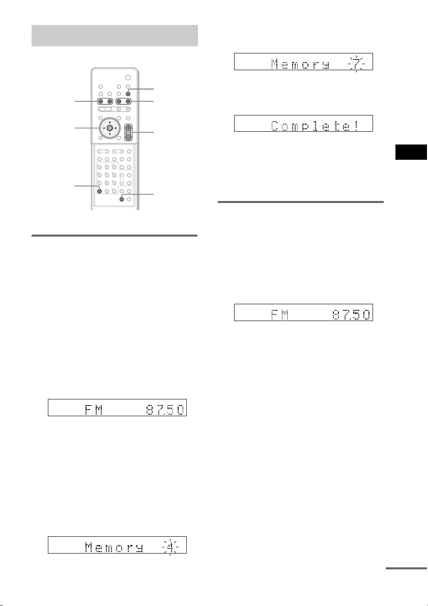
Enjoying the Radio
6 Press X/x to select the preset number
you want.
TUNED ST
FUNCTION
PRESET
–/+
C/X/x/c
ENTER
CLEAR
With cover opened.
TUNING –/+
VOLUME +/–
TUNER
MENU
Presetting radio stations
You can preset 20 FM stations, and 10 AM
stations. Before tuning, make sure to turn down
the volume to minimum.
1 Press FUNCTION repeatedly until the
band you want appears in the front
panel display.
2 Press and hold TUNING + or – until the
auto scanning starts.
Scanning stops when the system tunes in a
station. “TUNED” and “ST” (for stereo
program) appear in the front panel display.
TUNED ST
3 Press TUNER MENU.
4 Press C/X/x/c repeatedly until
“Memory?” appears in the front panel
display.
5 Press ENTER.
A preset number appears in the front panel
display.
TUNED ST
7 Press ENTER.
The station is stored.
TUNED ST
8 Repeat 1 to 7 to store other stations.
To change the preset number
Restart from Step 1.
Listening to the radio
Preset radio stations in the system’s memory
first (see “Presetting radio stations” (page 75)).
1 Press FUNCTION repeatedly until “FM”
or “AM” appears in the front panel
display.
The last received station is tuned in.
TUNED ST
2 Press PRESET + or – repeatedly to
select the preset station you want.
Each time you press the button, the system
tunes in one preset station.
3 Adjust the volume by pressing
VOLUME +/–.
To turn off the radio
Press "/1.
To listen to non-preset radio
stations
Use manual or automatic tuning in Step 2.
For manual tuning, press TUNING + or –
repeatedly.
For automatic tuning, press and hold TUNING +
or –. Press x when you stop the automatic
tuning.
Other Operations
continued
75
GB
Page 76

Tip
• If an FM program is noisy, press FM MODE so that
“MONO” appears in the front panel display. There
will be no stereo effect, but the reception will
improve. Press the button again to restore the stereo
effect.
• To improve reception, reorient the supplied antennas
(aerials).
• You can check the frequency by pressing DISPLAY
repeatedly (page 76).
Naming preset stations
You can enter a name for preset stations. These
names (for example, “XYZ”) appear in the
system’s front panel display when a station is
selected.
Note that no more than one name can be entered
for each preset station.
1 Press FUNCTION repeatedly until “FM”
or “AM” appears in the front panel
display.
The last station you received is tuned in.
2 Press PRESET + or – repeatedly to
select the preset station you want to
create an index name for.
3 Press TUNER MENU.
4 Press C/X/x/c repeatedly until “Name
In?” appears in the front panel display.
TUNED ST
Viewing the Station Name or
Frequency in the front panel
display
When the system is set to “TUNER AM” or
“TUNER FM,” you can check the frequency
using the front panel display.
Press DISPLAY.
Each time you press DISPLAY, the display
changes as shown in the charts.
t Station name*
Frequency*
*1This is displayed if you have entered a name for a
preset station (page 76).
*2Returns to the original display when several seconds
has elapsed.
1
r
2
5 Press ENTER.
6 Create a name by using the cursor
buttons.
Press X/x to select a character, then press c
to move the cursor to the next position.
Letters, numbers, and other symbols can be
input for a radio station name.
If you make a mistake
Press C/c repeatedly until the character to
be changed flashes, then press X/x to select
the desired character.
To erase the character, press C/c
repeatedly until the character to be erased
flashes, then press CLEAR.
7 Press ENTER.
The station name is stored.
GB
76
Page 77

Using the Radio Data
Using the Sleep Timer
System (RDS)
(Except for Russian model)
What is the Radio Data
System?
The Radio Data System (RDS) is a broadcasting
service that allows radio stations to send
additional information along with the regular
program signal. This tuner offers convenient
RDS features, such as station name display.
RDS is available only for FM stations.*
Note
• RDS may not work properly if the station you are
tuned to is not transmitting the RDS signal properly,
or if the signal strength is weak.
* Not all FM stations provide RDS service, nor do they
provide the same type of services. If you are not familiar
with the RDS system, check with your local radio
stations for details on RDS services in your area.
Receiving RDS broadcasts
Simply select a station from the FM band.
When you tune in a station that provides RDS
services, the station name* appears in the
TUNER information.
* If an RDS broadcast is not received, the station
name may not appear in the display.
You can set the system to turn off at a preset
time, so you can fall asleep listening to music.
You can preset the time in 10 minutes
decrements.
SLEEP
Other Operations
Press SLEEP.
Each time you press this button, the minutes
display (the remaining time) changes as follows:
SLEEP 90M t SLEEP 80M t SLEEP 70M
Rr
SLEEP OFF T SLEEP 10M ..... SLEEP 60M
To check the remaining time
Press SLEEP once.
To change the remaining time
Press SLEEP repeatedly to select the desired
time.
To cancel the Sleep Timer
function
Press SLEEP repeatedly until “SLEEP OFF”
appears in the front panel display.
77
GB
Page 78

Changing the Brightness
Returning to the Default
of the Front Panel Display
The brightness of the front panel display can be
set to either of 2 levels.
X/x/c
ENTER
AMP MENU
With cover opened.
1 Press AMP MENU.
2 Press X/x repeatedly until “DIMMER”
appears in the front panel display, then
press ENTER or c.
3 Press X/x to select the brightness of
the front panel display.
DIMMER OFF: Bright.
DIMMER ON: The front panel display
becomes dark and the Sound Field indicator
turns off.
4 Press ENTER or AMP MENU.
The AMP menu turns off.
Settings
You can return the system parameters, such as
preset stations, to the default settings.
"/1
VOLUME–
FUNCTION
1 Press "/1 to turn on the system.
2 Press and hold in order FUNCTION,
VOLUME–, "/1 on the system.
“COLD RESET” appears in the front panel
display and the default settings are returned.
78
GB
Page 79

Settings and Adjustments
Using the Setup Display
By using the Setup Display, you can make
various adjustments to items such as picture and
sound. You can also set a language for the
subtitles and the Setup Display, among other
things. For details on each Setup Display item,
see pages from 80 to 83. For an overall list of
Setup Display items, see page 99.
Note
• Playback settings stored in the disc take priority over
the Setup Display settings and not all the functions
described may work.
x
X/x
ENTER
DISPLAY
1 Press DISPLAY. (If a disc is playing,
press x to stop playback, then press
DISPLAY.)
The Control Menu appears.
2 Press X/x to select [SETUP],
then press ENTER.
The options for [SETUP] appear.
)
1 2 ( 2 7
)
1 8 ( 3 4
: :
QUICK
QUICK
CUSTOM
RESET
DVD VIDEO
LANGUAGE SETUP
OSD:
MENU:
AUDIO:
SUBTITLE:
ENGLISH
ENGLISH
ORIGINAL
AUDIO FOLLOW
4 Press X/x to select the setup item from
the displayed list: [LANGUAGE
SETUP], [SCREEN SETUP], [CUSTOM
SETUP], or [SPEAKER SETUP]. Then
press ENTER.
The Setup item is selected.
Example: [SCREEN SETUP]
Selected item
SCREEN SETUP
TV TYPE:
SCREEN SAVER:
BACKGROUND:ONJACKET PICTURE
LINE:
4:3 OUTPUT:
Setup items
16:9
VIDEO
FULL
5 Select an item using X/x, then press
ENTER.
The options for the selected item appear.
Example: [TV TYPE]
SCREEN SETUP
TV TYPE:
SCREEN SAVER:
BACKGROUND:
LINE:
4:3 OUTPUT:
4:3 LETTER BOX
16:9
16:9
4:3 PAN SCAN
FULL
Options
6 Select a setting using X/x, then press
ENTER.
The setting is selected and setup is
complete.
Settings and Adjustments
BNR
3 Press X/x to select [CUSTOM], then
press ENTER.
The Setup Display appears.
continued
79
GB
Page 80

SCREEN SETUP
TV TYPE:
SCREEN SAVER:
BACKGROUND:
LINE:
4:3 OUTPUT:
JACKET PICTURE
Selected setting
16:9
ON
VIDEO
FULL
To reset all of the [SETUP]
settings
1 Select [RESET] in Step 3 and press ENTER.
2 Select [YES] using X/x.
You can also quit the process and return to
the Control Menu by selecting [NO] here.
3 Press ENTER.
All the settings explained on pages 80 to 83
return to the default settings*. Do not press
[/1 while resetting the system as it takes a
few seconds to complete.
* Except for Parental Control settings.
Note
• When you turn the system on after resetting, the guide
message appears on the TV screen. To perform the
Quick Setup (page 30), press ENTER, to return to
normal screen, press CLEAR.
Setting the Display or Sound Track Language
[LANGUAGE SETUP]
[LANGUAGE SETUP] allows you to set
various languages for the on-screen display or
sound track.
Select [LANGUAGE SETUP] in the Setup
Display. To use the display, see “Using the
Setup Display” (page 79).
LANGUAGE SETUP
OSD:
MENU:
AUDIO:
SUBTITLE:
x [OSD] (On-Screen Display)
Switches the display language on the screen.
x [MENU] (DVD VIDEO only)
You can select the desired language for the
disc’s menu.
x [AUDIO] (DVD VIDEO only)
Switches the language of the sound track.
When you select [ORIGINAL], the language
given priority in the disc is selected.
x [SUBTITLE] (DVD VIDEO only)
Switches the language of the subtitle recorded
on the DVD VIDEO.
When you select [AUDIO FOLLOW], the
language for the subtitles changes according to
the language you selected for the sound track.
Tip
• If you select [OTHERS t] in [MENU], [AUDIO],
and [SUBTITLE], select and enter a language code
from “Language Code List” (page 93) using the
number buttons.
Note
• When you select a language in [MENU], [AUDIO],
or [SUBTITLE] that is not recorded on the DVD
VIDEO, one of the recorded languages will be
automatically selected (depending on the disc, the
language may not be selected automatically).
ENGLISH
ENGLISH
ORIGINAL
AUDIO FOLLOW
80
GB
Page 81

Settings for the Display
SCREEN SETUP
SCREEN SAVER:
BACKGROUND:
TV TYPE: 16:9
ON
JACKET PICTURE
LINE:
VIDEO
4:3 OUTPUT:
FULL
[SCREEN SETUP]
[16:9]
Choose settings according to the TV to be
connected.
Select [SCREEN SETUP] in the Setup Display.
To use the display, see “Using the Setup
Display” (page 79).
The default settings are underlined.
x [TV TYPE]
Selects the aspect ratio of the connected TV (4:3
standard or wide).
The default setting varies, depending on the
country model.
[16:9]
[4:3 LETTER
BOX]
[4:3 PAN SCAN]
Select this when you connect a
wide-screen TV or a TV with a
wide mode function.
Select this when you connect a 4:3
screen TV. Displays a wide picture
with bands on the upper and lower
portions of the screen.
Select this when you connect a 4:3
screen TV. Automatically displays
the wide picture on the entire
screen and cuts off the portions
that do not fit.
[4:3 LETTER BOX]
[4:3 PAN SCAN]
Note
• Depending on the DVD, [4:3 LETTER BOX] may be
selected automatically ins tead of [4:3 PAN SCAN] or
vice versa.
x [SCREEN SAVER]
The screen saver image appears when you leave
the system in pause or stop mode for 15
minutes,
or when you play back a Super Audio CD, CD, or
DATA CD (MP3 audio) for more than 15
minutes. The screen saver will help prevent your
display device from becoming damaged
(ghosting). Press
[ON]
[OFF]
H
to turn off the screen saver.
Turns on the screen saver.
Turns off the screen saver.
x [BACKGROUND]
The background can be set/displayed during the
following:
– When a DVD or Video CD, DATA CD
(JPEG files) are stopped.
– When a Super Audio CD, CD, or DATA CD
(MP3 audio) are played back or stopped.
Settings and Adjustments
[JACKET
PICTURE]
[GRAPHICS]
[BLUE]
[BLACK]
The jacket picture (still picture)
appears, but only when the jacket
picture is already recorded on the
disc (CD-EXTRA, etc.). If the
disc does not contain a jacket
picture, the [GRAPHICS] picture
appears.
A preset picture stored in the
system appears.
The background color is blue.
The background color is black.
continued
81
GB
Page 82

x [LINE]
Selects the output method for video signals from
the EURO AV T OUTPUT (TO TV) jack on
the rear panel of the system.
Custom Settings
[CUSTOM SETUP]
[VIDEO]
[RGB]
Note
• If your TV does not accept RGB signals, no picture
appears on the TV screen even if you select [RGB].
Refer to the instructions supplied with your TV.
Outputs video signals.
Outputs RGB signals.
x [4:3 OUTPUT]
This setting is effective only when you set [TV
TYPE] in [SCREEN SETUP] to [16:9]
(page 81)
. Adjust this to watch 4:3 aspect ratio
progressive signals. If you can change the aspect
ratio on your progressive format (525p/625p)
compatible TV, change the setting on your TV, not
the system.
Note
• This setting is effective only when “P AUTO
(PROGRESSIVE AUTO)” or “P VIDEO
(PROGRESSIVE VIDEO)” is selected by using
PROGRESSIVE (page 22).
[FULL]
[NORMAL]
Select this when you can change
the aspect ratio on your TV.
Select this when you cannot
change the aspect ratio on your
TV. Shows a 16:9 aspect ratio
signal with black bands on left and
right sides of the image.
Use this to set up playback-related (and other)
settings.
Select [CUSTOM SETUP] in the Setup Display.
To use the display, see “Using the Setup
Display” (page 79).
The default settings are underlined.
CUSTOM SETUP
PAUSE MODE:
TRACK SELECTION:
MULTI-DISC RESUME:
DivX:
Registration Code
AUTO
OFF
ON
x [PAUSE MODE] (DVD VIDEO/DVD-RW
only)
Selects the picture in pause mode.
[AUTO]
[FRAME]
The picture, including subjects
that move dynamically, is output
with no jitter. Normally select this
position.
The picture, including subjects
that do not move dynamically, is
output in high resolution.
x [TRACK SELECTION] (DVD VIDEO only)
Gives the sound track which contains the highest
number of channels priority when you play a
DVD VIDEO on which multiple audio formats
(PCM, DTS, MPEG audio, or Dolby Digital
format) are recorded.
82
[OFF]
16:9 aspect ratio TV
GB
[AUTO]
Note
• When you set the item to [AUTO], the language may
change. The [TRACK SELECTION] setting has
higher priority than the [AUDIO] settings in
[LANGUAGE SETUP] (page 80). (Depending on
the disc, this function may not work.)
No priority given.
Priority given.
Page 83

• If PCM, DTS, Dolby Digital sound, and MPEG audio
tracks have the same number of channels, the system
selects PCM, DTS, Dolby Digital sound, and MPEG
audio tracks in this order.
x [MULTI-DISC RESUME] (DVD VIDEO/
VIDEO CD only)
Switches the Multi-disc Resume setting on or
off. Resume playback point can be stored in
memory for up to 40 different DVD VIDEO/
VIDEO CD discs (page 41).
[ON]
[OFF]
x [DivX]
Stores the resume settings in
memory for up to 40 discs.
Does not store the resume settings
in memory. Playback restarts at
the resume point only for the
current disc in the system.
Displays the registration code for this system.
For more information, go to
http://www.divx.com
on the Internet.
Speaker Setting (Subwoofer)
[SPEAKER SETUP]
To obtain the best possible sound, you can
change the level of the subwoofer.
Select [SPEAKER SETUP] in the Setup
Display. For details, see “Using the Setup
Display” (page 79).
The default setting is underlined.
SPEAKER SETUP
LEVEL:
x LEVEL
You can change the level of the subwoofer as
follows.
Settings and Adjustments
[SUBWOOFER]
0dB
Tip
• You can also pres s WOOFER to adjust the subwoofer
level.
Set this between -6 dB and +6
dB in 1 dB increments.
83
GB
Page 84

Additional Information
Precautions
On your TV’s color
• If the speakers should cause the TV screen to have
color irregularity, turn off the TV then turn it on after
15 to 30 minutes. If color irregularity should persist,
place the speakers farther away from the set.
On placement
• Place the system in a location with adequate
ventilation to prevent heat build-up in the system.
• At high volume, over long periods of time, the cabinet
becomes hot to the touch. This is not a malfunction.
However, touching the cabinet sh ould be avoided. Do
not place the unit in a confined space where
ventilation is poor as this may cause overheating.
• Do not block the ventilation slots by putting anything
on the system. The system is equipped with a high
power amplifier. If the ventilation slots are blocked,
the unit can overheat and malfunction.
• Do not place t he system on a soft surface such as a rug
and do not block the ventilation holes.
• Do not place the system in a location near heat
sources, or in a place subject to direct sunlight,
excessive dust, or mechanical shock.
On operation
• If the system is br ought directly from a cold to a warm
location, or is placed in a very damp room, moisture
may condense on the lenses inside the system. Should
this occur, the system may not operate properly. In
this case, remove the disc and leave the system turned
on for about half an hour until the moisture
evaporates.
• When you move the system, take out any disc. If you
don’t, the disc may be damaged.
On adjusting volume
• Do not turn up the volume while listening to a section
with very low level inputs or no audio signals. If you
do, the speakers may be damaged when a peak level
section is suddenly played.
On cleaning
• Clean the cabinet, panel, and controls with a soft cloth
slightly moistened with a mild detergent solution. Do
not use any type of abrasive pad, scouring powder or
solvent such as alcohol or benzine.
If you have any questions or problems concerning
your system, please consult your nearest Sony dealer.
On cleaning discs, disc/lens
cleaner
• Do not use a commercially available cleaning disc
or disc/lens cleaner (wet or spray type). These may
cause apparatus to malfunction.
IMPORTANT NOTICE
Caution: This system is capable of holding a still
video image or on-screen display image on your
television screen indefinitely. If you leave the still
video image or on-screen display image displayed
on your TV for an extended period of time you risk
permanent damage to your television screen.
Projection televisions are especially susceptible to
this.
On moving the system
When you carry the system, use the following
procedure to protect the inner mechanism.
1 Press FUNCTION repeatedly to select
“DVD.”
2 Make sure that the disc is removed from the
system.
3 Press x and "/1 simultaneously.
“MECHA LOCK” appears in the front panel
display after “STANDBY.”
4 Remove the AC power cord (mains lead)
from the wall outlet (mains).
84
GB
Page 85

Notes about the Discs Troubleshooting
On handling discs
• To keep the disc clean, handle the disc by its
edge. Do not touch the surface.
• Do not stick paper or tape on the disc.
• Do not expose the disc to direct sunlight or
heat sources such as hot air ducts, or leave it in
a car parked in direct sunlight as the
temperature may rise considerably inside the
car.
• After playing, store the disc in its case.
On cleaning
• Before playing, clean the disc with a cleaning
cloth.
Wipe the disc from the center out.
• Do not use solvents such as benzine, thinner,
commercially available cleaners, or anti-static
spray intended for vinyl LPs.
This system can only play back a standard
circular disc. Using neither standard nor circular
discs (e.g., card, heart, or star shape) may cause
a malfunction.
Do not use a disc that has a commercially
available accessory attached, such as a label or
ring.
If you experience any of the following
difficulties while using the system, use this
troubleshooting guide to help remedy the
problem before requesting repairs. Should any
problem persist, consult your nearest Sony
dealer.
Note that if service personnel changes some
parts during repair, these parts may be retained.
Power
The power is not turned on.
• Check that the AC power cord (mains lead) is
connected securely.
If “PROTECT” and “UNPLUG” appears
alternately in the front panel display.
Immediately unplug the AC power cord (mains
lead) and check the following items.
• Are you using only the specified speakers?
• Is anything blocking the ventilation holes of the
system?
After checking the above items and fixing any
problems, connect the AC power cord (mains lead)
again and turn on the system. If the cause of the
problem cannot be found even after checking all the
above items, consult your nearest Sony dealer.
Picture
There is no picture.
• The video connecting cords are not connected
securely.
• The video connecting cords are damaged.
• The system is not connected to the correct TV
input jack (page 20).
• The video input on the TV is not set so that you
can view pictures from the system.
• You have set progressive format but your TV
cannot accept the signal in progressive format. In
this case, return the setting to interlace format (the
default setting) (page 22).
• Even if your TV is compatible with progressive
format (525p/625p) signals, the image may be
affected when you set progressive format. In this
case, return the setting to interlace format (the
default setting) (page 22).
• The SCART (EURO AV) cord is not connected
securely.
• The SCART (EURO AV) cord is damaged.
• The system is not connected to the correct
EURO AV t INPUT jack (page 20).
continued
85
Additional Information
GB
Page 86

• The video input on the TV is not set so that you
can view pictures from the system.
Picture noise appears.
• The disc is dirty or flawed.
• If the picture output from your system goes
through your VCR to get to your TV, the copyprotection signal applied to some DVD programs
could affect picture quality. If you still experience
problems even when you connect your system
directly to your TV, try connecting your system to
your TV’s S video input (page 20, 26).
Even though you set the aspect ratio in [TV
TYPE] of [SCREEN SETUP], the picture does
not fill the screen.
• The aspect ratio on the disc is fixed.
Color irregularity occurs on the TV screen.
The subwoofer and the front speakers in this system
are magnetically shielded to prevent magnetic
leakage. However, some leakage may occur, as a
high-strength magnet is employed. If this happens,
check the following items:
• If the speakers are used with a CRT-based TV or
projector, install the speakers at least 0.3 m from
the TV set.
• If the color irregularity persists, turn off the TV set
once, then turn it on after 15 to 30 minutes.
• If howling occurs, reposition the speakers farther
away from the TV set.
• Make sure that no magnetic object (magnetic latch
on a TV stand, health care device, toy, etc.) is
placed near the speakers.
Sound
There is no sound.
• The speaker cord is not connected securely.
• Press MUTING on the remote if “MUTING ON”
is displayed in the front panel display.
• The system is in pause mode or in Slow-motion
Play mode. Press H to return to normal play
mode.
• Fast forward or fast reverse is performed. Press
H to return to normal play mode.
• Check the speaker connections (page 17).
The left and right sounds are unbalanced or
reversed.
• Check that the speakers and components are
connected correctly and securely.
There is no sound from the subwoofer.
• Check the speaker connections and settings
(page 17).
• When the Setup Disc is used, the volume of the
subwoofer may be low. This is by default, and not
a malfunction.
Severe hum or noise is heard.
• Check that the speakers and components are
connected securely.
• Check that the connecting cords are away from a
transformer or motor, and at least 3 meters away
from your TV set or a fluorescent light.
• Move your TV away from the audio components.
• The plugs and jacks are dirty. Wipe them with a
cloth slightly moistened with alcohol.
• Clean the disc.
The sound loses stereo effect when you play a
VIDEO CD, CD or DATA CD (MP3 audio).
• Set [AUDIO] to [STEREO] by pressing AUDIO
(page 71).
• Make sure the system is connected properly.
The surround effect is difficult to hear when
you are playing a Dolby Digital, DTS, or MPEG
audio sound track.
• Make sure the sound field is set to “FOCUS
SURROUND” or “WIDE SURROUND”
(page 38).
• Check the speaker connections and settings
(page 17).
• Depending on the DVD, the output signal may not
be the entire 5.1 channel. It may be monaural or
stereo even if the sound track is recorded in Dolby
Digital or MPEG audio format.
Operation
Radio stations cannot be tuned in.
• Check that the antenna (aerial) is connected
securely. Adjust the antenna (aerial) or connect an
external antenna (aerial) if necessary.
• The signal strength of the stations is too weak
(when tuning in with automatic tun ing). Use direct
tuning.
• No stations have been preset or the preset stations
have been cleared (when tuning by scanning
preset stations). Preset the stations (page 75).
• Press DISPLAY so that the frequency appears in
the front panel display.
The remote does not function.
• There are obstacles between the remote and the
system.
• The distance between the remote and the system is
too far.
• The remote is not pointed at the remote sensor on
the system.
• The batteries in the remote are weak.
86
GB
Page 87

The disc does not play.
• There is no disc inserted.
• The disc is upside down.
Insert the disc with the playback side facing down.
• The disc is skewed on the disc tray.
• The system cannot play CD-ROMs, etc. (page 7).
• The region code on the DVD does not match the
system.
• Moisture has condensed inside the system and
may cause damage to the lenses. Remove the disc
and leave the system turned on for about half an
hour.
The MP3 audio track cannot be played.
• The DATA CD is not recorded in the MP3 format
that conforms to ISO 9660 Level 1/Level 2 or
Joliet.
• The MP3 audio track does not have the extension
“.MP3.”
• The data is not formatted in MP3 even though it
has the extension “.MP3.”
• The data is not MPEG1 Audio Layer 3 data.
• The system cannot play audio tracks in MP3PRO
format.
• The [MODE (MP3, JPEG)] setting has been set to
[IMAGE (JPEG)] (page 51).
• The DATA CD contains a DivX video file.
• This system cannot play MP3 audio files recorded
on DATA DVDs.
The JPEG image file cannot be played.
• The DATA CD is not recorded in a JPEG format
that conforms to ISO 9660 Level 1/Level 2, or
Joliet.
• It has an extension other than “.JPEG” or “.JPG.”
• It is larger than 3,072 (width) × 2,048 (height) in
normal mode, or more than 3,300,000 pixels in
Progressive JPEG.
• It does not fit the screen (those images are
reduced).
• The [MODE (MP3, JPEG)] setting has been set to
[AUDIO (MP3)] (page 51).
• The DATA CD contains a DivX video file.
• This system cannot play JPEG image files
recorded on DATA DVDs.
The MP3 audio tracks and JPEG image file
starts playing simultaneously.
• [AUTO] has been selected in [MODE (MP3,
JPEG)] (page 51).
The DivX video file cannot be played.
• The file is not created in DivX format.
• The file has an extension other than “.AVI” or
“.DIVX.”
• The DATA CD (DivX video)/DATA DVD is not
created in a DivX format that conforms to ISO
9660 Level 1/Level 2 or, Joliet/UDF.
• The DivX video file is larger than 720 (width)
576 (height).
The titles of album/track/file name are not
displayed correctly.
• The system can only display numbers and letters
of the alphabets. Other characters are displayed as
[*].
A disc does not start playing from the
beginning.
• Program play, Shuffle Play, or Repeat Play has
been selected.
Press CLEAR to cancel these functions before
playing a disc.
• Resume Play has been selected.
During stop, press x on the system or the remote
and then start playback (page 41).
• The title, DVD or PBC menu automatically
appears on the TV screen.
The system starts playing the disc
automatically.
• The DVD features an auto playback function.
Playback stops automatically.
• Some discs may contain an auto pause signal.
While playing such a disc, the system stops
playback at the auto pause signal.
You cannot perform some functions such as
Stop, Search, Slow-motion Play, or Repeat
Play.
• Depending on the disc, you may not be able to
perform some of the operations above. See the
operating manual that came with the disc.
Messages do not appear on the screen in the
language you want.
• In the Setup Display, select the desired language
for the on-screen display in [OSD] under
[LANGUAGE SETUP] (page 80).
×
Additional Information
continued
87
GB
Page 88

The language for the sound track cannot be
changed.
• Multilingual tracks are not recorded on the DVD
being played.
• The DVD prohibits changing the language for the
sound track.
The subtitle language cannot be changed.
• Multilingual subtitles are not recorded on the
DVD being played.
• The DVD prohibits changing the subtitles.
The subtitle cannot be turned off.
• The DVD prohibits turning off subtitles.
The angles cannot be changed.
• Multi-angles are not recorded on the DVD being
played (page 63).
• The DVD prohibits changing the angles.
A disc cannot be ejected and “LOCKED”
appears in the front panel display.
• Contact you r Sony dealer or local authorized Sony
service facility.
[Data error] appears on the TV screen when
playing a DATA CD or DATA DVD.
• The MP3 audio track/JPEG image file/DivX
video file you want to play is broken.
• The data is not MPEG1 Audio Layer 3 data.
• The JPEG image file format does not conform to
DCF.
• The JPEG image file has the extension “.JPG” or
“.JPEG,” but is not in JPEG format.
• The file you want to play has the extension “.AVI”
or “.DIVX” but is not in DivX format, or is in
DivX format but does not conform to a DivX
Certified profiles.
The system does not work normally.
• Disconnect the AC power cord (mains lead) from
the wall outlet (mains), then reconnect after
several minutes.
[DEMO PLAY] appears in the front panel
display.
• Contact you r Sony dealer or local authorized Sony
service facility.
Self-diagnosis Function
(When letters/numbers appear in the display)
When the self-diagnosis function is activated to
prevent the system from malfunctioning, a 5character service number (e.g., C 13 50) with a
combination of a letter and 4 digits appears on
the screen and the front panel display. In this
case, check the following table.
C:13:50
First 3
characters of
the service
number
C 13 The disc is dirty.
C 31 The disc is not inserted correctly.
E XX
(xx is a number)
Cause and/or corrective action
,Clean the disc with a soft cloth
(page 85).
,Restart the system, then re-inse rt
the disc correctly.
To prevent a malfunction, the
system has performed the selfdiagnosis function.
,Contact your nearest Sony
dealer or local authorized Sony
service facility and give the 5character service number.
Example: E 61 10
88
GB
Page 89

Specifications
Amplifier section
Front Power output (rated): 40 W
+ 40 W (6 ohms, 1 kHz,
THD 1 %)
Continuous RMS power
output (reference): 50 W +
50 W (6 ohms at 1 kHz,
THD 10 %)
Front surround* Power output (rated): 40 W
+ 40 W (6 ohms, 1 kHz,
THD 1 %)
Continuous RMS power
output (reference): 50 W +
50 W (6 ohms at 1 kHz,
THD 10 %)
Subwoofer Power output (rated): 40 W
+ 40 W (6 ohms, 100 Hz,
THD 1 %)
Continuous RMS power
output (reference): 50 W +
50 W (6 ohms at 100 Hz,
THD 10 %)
* Depending on the source, there may be no sound
output.
Inputs (Analogue)
VIDEO 1/SAT 1, VIDEO 2/SAT 2
Sensitivity: 250/450 mV
RMS
Impedance: 50 kilohms
TV Sensitivity: 450 mV RMS
Impedance: 50 kilohms
Inputs (Digital)
VIDEO 1/SAT 1, VIDEO 2/SAT 2, TV
Impedance: 75 ohms
Super Audio CD/DVD system
Laser Semiconductor laser
(DVD: λ = 650 nm)
(CD: λ = 790 nm)
Emission duration:
continuous
Signal format system NTSC/PAL
Tuner section
System PLL quartz-locked digital
synthesizer system
FM tuner section
Tuning range 87.5 – 108.0 MHz
(50 kHz step)
Antenna (aerial) FM wire antenna (aerial)
Antenna (aerial) terminals 75 ohms, unbalanced
Intermediate frequency 10.7 MHz
AM tuner section
Tuning range 531 – 1,602 kHz (with the
interval set at 9 kHz)
Antenna (aerial) AM loop antenna (aerial)
Intermediate frequency 450 kHz
Video section
Outputs Video: 1 Vp-p 75 ohms
S video:
Y: 1 Vp-p 75 ohms
C: 0.286 Vp-p 75 ohms
COMPONENT:
Y: 1 Vp-p 75 ohms
PB/CB, PR/CR: 0.7 Vp-p
75 ohms
Input VIDEO: 1 Vp-p 75 ohms
S video:
Y: 1 Vp-p 75 ohms
C: 0.286 Vp-p 75 ohms
Speakers
Front
Speaker system Bass reflex, magnetically
shielded
Speaker unit 50 mm cone type × 2
Rated impedance 6 ohms
Dimensions (approx.) 162 × 78 × 134 mm
(w/h/d)
Mass (approx.) 0.8 kg
Subwoofer
Speaker system Bass reflex, magnetically
shielded
Speaker unit 150 mm cone type × 2
Rated impedance 6 ohms
Dimensions (approx.) 205 × 440 × 400 mm
(w/h/d)
Mass (approx.) 9.3 kg
General
Power requirements 220 – 240 V AC, 50/60 Hz
Power consumption On: 85 W
Standby: 0.3 W (at the
Power Saving Mode)
Dimensions (approx.) 380 × 76 × 293 mm (w/h/d)
incl. projecting parts
Mass (approx.) 4.5 kg
Supplied accessories See page 13.
Additional Information
Design and specifications are subject to change
without notice.
89
GB
Page 90

Glossary
Album
Section of a music piece or an image on a data
CD containing MP3 audio tracks or JPEG files.
Chapter
Subdivision of a title on a DVD. A title is
composed of several chapters.
®
DivX
Digital video technology created by
DivXNetworks, Inc. Videos encoded with DivX
technology are among the highest quality with a
relatively small file size.
Dolby Digital
This movie theater sound format is more
advanced than Dolby Surround Pro Logic. In
this format, the surround speakers output stereo
sound with an expanded frequency range, and a
subwoofer channel for deep bass is
independently provided. This format is also
called “5.1” with the subwoofer channel
designed as the 0.1 channel (since it functions
only when a deep bass effect is needed). All six
channels in this format are recorded separately
for superior channel separation. Furthermore,
since all the signals are processed digitally, less
signal degradation occurs.
Dolby Pro Logic II
Dolby Pro Logic II creates five full-bandwidth
output channels from 2 channel sources. This is
done using an advanced, high-purity matrix
surround decoder that extracts the spatial
properties of the original recording without
adding any new sounds or tonal colorations.
DTS
Digital audio compression technology
developed by Digital Theater Systems, Inc. This
technology conforms to 5.1-channel surround.
This format comprises of stereo rear channel and
there is discrete subwoofer channel in this
format. DTS provides the same 5.1 discrete
channels of high quality digital audio. The good
channel separation is realized due to the all
channel data being recorded discretely and
processed in digitally.
DVD
A disc that contains up to 8 hours of moving
pictures even though its diameter is the same as
a CD.
The data capacity of a single-layer and singlesided DVD, at 4.7 GB (Giga Byte), is 7 times
that of a CD. Furthermore, the data capacity of a
dual-layer and single-sided DVD is 8.5 GB, a
single-layer and double-sided DVD 9.4 GB, and
a dual-layer and double-sided DVD 17 GB.
The picture data uses the MPEG 2 format, one of
a worldwide standard of digital compression
technology. The picture data is compressed to
about 1/40 of its original size. The DVD also
uses the variable rate coding technology that
processes allocated data according to the status
of the picture.
The audio data is recorded in Dolby Digital as
well as in PCM, allowing you to enjoy more
realistic audio presence.
Furthermore, various advanced functions such
as the multi-angle, multilingual, and Parental
Control functions are provided with the DVD.
DVD-RW
A DVD-RW is a recordable and rewritable disc
that is the same size as a DVD VIDEO. The
DVD-RW has two different modes: VR mode
and Video mode. DVD-RWs created in Video
mode have the same format as a DVD VIDEO,
while discs created in VR (Video Recording)
mode allow the contents to be programmed or
edited.
DVD+RW
A DVD+RW (plus RW) is a recordable and
rewritable disc. DVD+RWs use a recording
format that is comparable to the DVD VIDEO
format.
File
A JPEG image recorded on a DATA CD or a
DivX video on a DATA CD/DATA DVD.
(“File” is an exclusive definition for this
system.) A single file consists of a single image
or movie.
Film based software, Video based
software
DVDs can be classified as Film based or Video
based software. Film based DVDs contain the
same images (24 frames per second) that are
shown at movie theaters. Video based DVDs,
90
GB
Page 91

such as television dramas or sit-coms, displays
images at 30 frames (or 60 fields) per second.
Interlace format
(Interlaced scanning)
The Interlace format is the NTSC standard
method for displaying TV images at 30 frames
per second. Each frame is scanned twice alternately between the even numbered scanning
lines and then odd numbered scanning lines, at
60 times per second.
Multi-angle function
Various angles of a scene, or viewpoints of the
video camera are recorded on some DVDs.
Multilingual function
Several languages for the sound or subtitles in a
picture are recorded on some DVDs.
Parental Control
A function of the DVD to limit playback of the
disc by the age of the users according to the
limitation level in each country. The limitation
varies from disc to disc; when it is activated,
playback is completely prohibited, violent
scenes are skipped or replaced with other scenes
and so on.
Playback Control (PBC)
Signals encoded on VIDEO CDs (Version 2.0)
to control playback.
By using menu screens recorded on VIDEO
CDs with PBC functions, you can enjoy playing
simple interactive programs, programs with
search functions, and so on.
Progressive format
(sequential scanning)
In contrast to the Interlace format, the
progressive format can reproduce 60 frames per
second by reproducing all scanning lines (525
lines for the NTSC system). The overall picture
quality increases and still images, text and
horizontal lines appear sharper. This format is
compatible with the 525 progressive format.
Region Code
This system is used to protect copyrights. A
region number is allocated on each DVD system
or DVD disc according to the sales region. Each
region code is shown on the system as well as on
the disc packaging. The system can play discs
that match its region code. The system can also
play discs with the “ ” mark. Even when the
ALL
region code is not shown on the DVD, the region
limit may still apply.
Scene
On a VIDEO CD with PBC (playback control)
functions, the menu screens, moving pictures
and still pictures are divided into sections called
“scenes.”
S-Force PRO Front Surround
Sony’s long-term involvement in surround
technology (and the vast amounts of acoustic
data accumulated as a result) has led to the
development of all-new processing method and
advanced DSP to handle this task effectively,
which we call S-Force PRO Front Surround.
Compared with previous front surround
technologies, S-Force PRO Front Surround
reproduces a more convincing sense of distance
and space, resulting in a true surround sound
experience without the need for rear speakers.
S-Master
S-Master is an all-digital amplifier technology
developed by Sony, which effectively
minimizes the occurrence of sound
fragmentation and jitter, delivering superb
dialog clarity and faithful reproduction of the
original sound. The compact amplifier section
supports a higher power efficiency and
improved thermal performance.
Title
The longest section of a picture or music feature
on a DVD, movie, etc., in video software, or the
entire album in audio software.
Track
Section of a picture or a music piece on a
VIDEO CD, CD, or MP3. An album is
composed of several tracks (MP3 only).
VIDEO CD
A compact disc that contains moving pictures.
The picture data uses the MPEG 1 format, one of
a worldwide standard of digital compression
technology. The picture data is compressed to
about 1/140 of its original size. Consequently, a
12 cm VIDEO CD can contain up to 74 minutes
of moving pictures.
VIDEO CDs also contain compact audio data.
Sounds outside the range of human hearing are
continued
91
Additional Information
GB
Page 92

compressed while sounds we can hear are not
compressed. VIDEO CDs can hold 6 times the
audio information of conventional audio CDs.
There are 2 versions of VIDEO CDs.
• Version 1.1: You can play only moving
pictures and sounds.
• Version 2.0: You can play high-resolution still
pictures and enjoy PBC functions.
This system conforms to both versions.
92
GB
Page 93

Language Code List
g
The language spellings conform to the ISO 639: 1988 (E/F) standard.
Code Language Code Language Code Language
1027 Afar
1028 Abkhazian
1032 Afrikaans
1039 Amharic
1044 Arabic
1045 Assamese
1051 Aymara
1052 Azerbaijani
1053 Bashkir
1057 Byelorussian
1059 Bulgarian
1060 Bihari
1061 Bislama
1066 Bengali; Bangla
1067 Tibetan
1070 Breton
1079 Catalan
1093 Corsican
1097 Czech
1103 Welsh
1105 Danish
1109 German
1130 Bhutani
1142 Greek
1144 English
1145 Esperanto
1149 Spanish
1150 Estonian
1151 Basque
1157 Persian
1165 Finnish
1166 Fiji
1171 Faroese
1174 French
1181 Frisian
1183 Irish
1186 Scots Gaelic
1194 Galician
1196 Guarani
1203 Gujarati
1209 Hausa
1217 Hindi
1226 Croatian
1229 Hungarian
1233 Armenian
1235 Interlingua
1239 Interlin
ue
1245 Inupiak
1248 Indonesian
1253 Icelandic
1254 Italian
1257 Hebrew
1261 Japanese
1269 Yiddish
1283 Javanese
1287 Georgian
1297 Kazakh
1298 Greenlandic
1299 Cambodian
1300 Kannada
1301 Korean
1305 Kashmiri
1307 Kurdish
1311 Kirghiz
1313 Latin
1326 Lingala
1327 Laothian
1332 Lithuanian
1334 Latvian; Lettish
1345 Malagasy
1347 Maori
1349 Macedonian
1350 Malayalam
1352 Mongolian
1353 Moldavian
1356 Marathi
1357 Malay
1358 Maltese
1363 Burmese
1365 Nauru
1369 Nepali
1376 Dutch
1379 Norwegian
1393 Occitan
1403 (Afan) Oromo
1408 Oriya
1417 Punjabi
1428 Polish
1435 Pashto; Pushto
1436 Portuguese
1463 Quechua
1481 Rhaeto-Romance
1482 Kirundi
1483 Romanian
1489 Russian
1491 Kinyarwanda
1495 Sanskrit
1498 Sindhi
1501 Sangho
1502 Serbo-Croatian
1503 Singhalese
1505 Slovak
1506 Slovenian
1507 Samoan
1508 Shona
1509 Somali
1511 Albanian
1512 Serbian
1513 Siswati
1514 Sesotho
1515 Sundanese
1516 Swedish
1517 Swahili
1521 Tamil
1525 Telugu
1527 Tajik
1528 Thai
1529 Tigrinya
1531 Turkmen
1532 Tagalog
1534 Setswana
1535 Tonga
1538 Turkish
1539 Tsonga
1540 Tatar
1543 Twi
1557 Ukrainian
1564 Urdu
1572 Uzbek
1581 Vietnamese
1587 Volap k
1613 Wolof
1632 Xhosa
1665 Yoruba
1684 Chinese
1697 Zulu
1703
Not specified
Additional Information
GB
93
Page 94
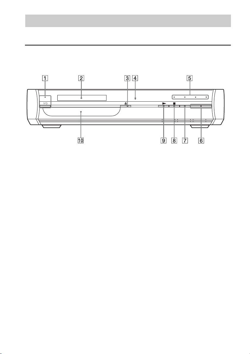
Index to Parts and Controls
For more information, refer to the pages indicated in parentheses.
Front panel
A "/1 (on/standby indicator) (29, 36, 78)
B Front panel display (95)
C Z (open/close) (34, 36)
D Remote sensor (14)
E Sound Field indicator (38)
F VOLUME –/+ (36, 78)
G FUNCTION (36, 78)
H x (stop) (29, 34, 36)
I N (play) (34, 36)
J Disc tray (34, 36)
94
GB
Page 95

Front panel display
About the indications in the front panel display
NIGHT TITLE CHAP REP REP1 SHUF PGM TUNED ST MONO
SLEEP
PROGRE SA-CD
NTSC
A/V SYNC
A Lights up when progressive signal is
output. (22)
B Current surround format (Except for
JPEG and Super Audio CD) (72)
C Lights up in SLEEP mode. (77)
D Playing status (DVD function only)
E Lights up in NIGHT mode. (73)
F Lights up when the time information of
a title or chapter appears in the front
panel display. (DVD only)
G Current play mode
H Lights up when a radio station is tuned.
(75)
I Lights up when a stereo broadcast is
tuned. (75)
J Lights up when listening the radio in
monaural effect. (75)
K Current disc type
L Lights up when “SYNC ON” is set in
“A/V SYNC.” (Except for Super Audio
CD and radio) (55)
M Lights up when playing NTSC discs
(DVD function only).
Additional Information
continued
95
GB
Page 96

Rear panel
DIGITAL OUT
OPTICAL
SPEAKER
VIDEO 1 / SAT 1
OPTICAL
VIDEO 2 / SAT 2
DIGITAL IN
COAXIAL
DIGITAL IN
COAXAL
TV
DIGITAL IN
COAXIAL
VIDEO 1 /
L
R
OUTPUT(TO TV
SAT 1
VIDEO 2 /
SAT 2
AUDIO INAUDIO IN
)
S-VIDEO IN
VIDEO 1 / SAT 1 VIDEO 2 / SAT 2
VIDEO IN
MONITOR OUT
S-VIDEO
VIDEO
COMPONENT VIDEO OUT
YPB/CBPR/C
ANTENNA
AM
FM
75
COAXIAL
R
A DIGITAL OUT OPTICAL jack (26)
B VIDEO 1/SAT 1DIGITAL IN (OPTICAL/
COAXIAL) jacks (26)
C AUDIO IN L/R (VIDEO 1/SAT1, VIDEO 2/
SAT 2, TV) jacks (26)
D VIDEO/S-VIDEO IN (VIDEO 1/SAT 1,
VIDEO 2/SAT 2, MONITOR OUT) jacks
(20, 26)
E EURO AV T OUTPUT (TO TV) jack (20,
24)
F ANTENNA (AM terminal/FM 75Ω
COAXIAL jack) (19)
G COMPONENT VIDEO OUT (Y, P
C
R) jacks (20)
B/CB, PR/
H TV DIGITAL IN COAXIAL jack (24)
I VIDEO 2/SAT 2 DIGITAL IN (COAXIAL)
jack (26)
J SPEAKER jack (16)
96
GB
Page 97

Remote
Open the
cover.
A TV (68, 69)
B SLEEP (77)
C SOUND FIELD (38)
D ./> PRESET –/+, TV CH –/+ (30,
36, 49, 53, 68, 69, 75)
E H (play) (34, 36, 49, 51, 53, 56)
The H button has a tactile dot.*
F TOP MENU (45)
G C/X/x/c/ENTER (30, 34, 38, 45, 47, 49,
51, 53, 55, 57, 59, 64, 68, 72, 74, 78, 79)
C/X/x/c
have tactile dots.*
H O RETURN (49, 53)
I ALBUM –/+ (36, 69)
J ANGLE (63)
K AUDIO (71)
The AUDIO button has a tactile dot.*
L SUBTITLE (63)
M Number buttons (45, 47, 57, 64, 68, 69)
The number 5 button has a tactile dot.*
N CLEAR, - (49, 57, 69, 75)
O ENTER
P PROGRESSIVE, TUNER MENU (22, 75)
Q TV [/1 (on/standby) (68)
R "/1 (on/standby) (29, 30, 36)
S THEATRE SYNC (69)
T TV/VIDEO (68, 69)
U FUNCTION (22, 36, 38, 72, 73, 75)
V m/M / SLOW, TUNING –/+ (56,
75)
W x (stop) (29, 34, 36, 46, 49, 51, 53, 64,
72, 79)
X X (pause) (36)
Y MUTING (36)
Z MENU (45, 49, 53)
wj VOLUME, TV VOL +/– (36, 68, 75)
The VOLUME, TV VOL + button has a
tactile dot.*
wk DISPLAY (10, 46, 51, 57, 59, 60, 64,
79)
wl / REPLAY, ADVANCE,
STEP (36, 56)
e; DISPLAY (60)
ea WOOFER (72)
es PICTURE NAVI (49, 59)
ed REPEAT (44)
ef FM MODE (75)
continued
97
Additional Information
GB
Page 98

eg TV CH –/+ (68)
The TV CH + button has a tactile dot.*
eh TV VOL +/– (68)
ej NIGHT (72)
ek SA-CD/CD (46)
el AMP MENU (38, 55, 72, 73, 74, 78)
* Use the tactile dot as a reference when operating the
system.
98
GB
Page 99

DVD Setup Display List
You can set the following items with the DVD Setup Display.
The order of the displayed items may be different from the actual display.
The default settings are underlined.
LANGUAGE SETUP
OSD
MENU
AUDIO
AUDIO
SUBTITLE
SUBTITLE
(Select the language you
want to use from the
displayed language list.)
(Select the language you
want to use from the
displayed language list.)
(Select the language you
(Select the language you
want to use from the
want to use from the
displayed language list.)
displayed language list.)
(Select the language you
want to use from the
displayed language list.)
CUSTOM SETUP
PAUSE
MODE
TRACK
SELECTION
MULTI-DISC
RESUME
DivX
AUTO
FRAME
OFF
AUTO
Registration Code t
ON
OFF
SCREEN SETUP
TV TYPE
SCREEN SAVER
BACKGROUND
LINE
4:3 OUTPUT
SPEAKER SETUP
LEVEL:
SUBWOOFER
16:9
4:3 LETTER BOX
4:3 PAN SCAN
ON
OFF
JACKET
PICTURE
GRAPHICS
BLUE
BLACK
VIDEO
RGB
FULL
NORMAL
(Select the subwoofer
level from – 6.0 dB to +
6.0 dB. The default level
is 0 dB.)
Additional Information
99
GB
Page 100

AMP Menu List
You can set the following items with AMP MENU on the remote.
The default settings are underlined.
AMP menu
AUDIO DRC DRC OFF
DUAL MONO MAIN
A/V SYNC SYNC OFF
DIMMER DIMMER OFF
SET VIDEO1
SET SAT1
SET VIDEO2
SET SAT2
AUTO MODE FOCUS SURR
NIGHT MODE NIGHT OFF
DRC STD
DRC MAX
SUB
MAIN+SUB
MAIN/SUB
SYNC ON
DIMMER ON
SET VIDEO1
SET SAT1
SET VIDEO1
SET SAT1
SET VIDEO2
SET SAT2
SET VIDEO2
SET SAT2
WIDE SURR
NIGHT ON
100
GB
 Loading...