

Sony DAV-HDX686W User Manual

4-122-239-13(1)
DVD Home Theatre
System
Operating Instructions
DAV-HDX589W / HDX686W
©2009 Sony Corporation
WARNING
To reduce the risk of fire or electric
shock, do not expose this apparatus to
rain or moisture.
Caution – The use of optical instruments
with this product will increase eye
hazard.
Do not install the appliance in a confined space, such
as a bookcase or built-in cabinet.
To reduce the risk of fire, do not cover the ventilation
opening of the apparatus with newspapers, tablecloths,
curtains, etc. Do not place the naked flame sources
such as lighted candles on the apparatus.
To reduce the risk of fire or electric shock, do not
expose this apparatus to dripping or splashing, and do
not place objects filled with liquids, such as vases, on
the apparatus.
Do not expose batteries or apparatus with batteryinstalled to excessive heat such as sunshine, fire or the
like.
To prevent injury, this apparatus must be securely
attached to the floor/wall in accordance with the
installation instructions.
Indoor use only.
For the customers in the U.S.A.
This symbol is intended to alert the user to
the presence of uninsulated “dangerous
voltage” within the product’s enclosure that
may be of sufficient magnitude to constitute
a risk of electric shock to persons.
This symbol is intended to alert the user to
the presence of important operating and
maintenance (servicing) instructions in the
literature accompanying the appliance.
Owner’s Record
The model and serial numbers are located on the rear
exterior of the unit. Record the serial number in the
space provided below. Refer to them whenever you
call upon your Sony dealer regarding this product.
Model No. DAV-HDX589W
Serial No.______________
Date of Manufacture Marking is located on the bottom
exterior.
This appliance is
classified as a CLASS 1
LASER product. This
marking is loca ted on the
rear exterior.
About the surround amplifier
• The nameplate is located on the side exterior.
• For the customers in the U.S.A.: Date of Manufacture
Marking is located on the bottom exterior.
Precautions
On power sources
• The unit is not disconnected from the mains as long
as it is connected to the AC outlet, even if the unit
itself has been turned off.
• As the main plug is used to disconnect the unit from
the mains, connect the unit to an easily accessible AC
outlet. Should you notice an abnormality in the unit,
disconnect the main plug from the AC outlet
immediately.
US
2
The following FCC statement applies only to the
version of this model manufactured for sale in the
USA. Other versions may not comply with FCC
technical regulations.
NOTE:
This equipment has been tested and found to comply
with the limits for a Class B digital device, pursuant to
Part 15 of the FCC Rules. These limits are designed to
provide reasonable protection against harmful
interference in a residential installation. This
equipment generates, uses, and can radiate radio
frequency energy and, if not installed and used in
accordance with the instructions, may cause harmful
interference to radio communications. However, there
is no guarantee that interference will not occur in a
particular installation. If this equipment does cause
harmful interference to radio or television reception,
which can be determined by turning the equipment off
and on, the user is encouraged to try to correct the
interference by one or more of the following measures:
– Reorient or relocate the receiving antenna (aerial).
– Increase the separation between the equipment and
receiver.

– Connect the equipment into an outlet on a circuit
different from that to which the receiver is
connected.
– Consult the dealer or an experienced radio/TV
technician for help.
CAUTION
You are cautioned that any changes or modifications
not expressly approved in this manual could void your
authority to operate this equipment.
been exposed to rain or moisture, does not operate
normally, or has been dropped.
®
ENERGY STAR
registered mark.
As an ENERGY STAR
Sony Corporation has determined
that this product meets the ENERGY
®
guidelines for energy
STAR
efficiency.
is a U.S.
®
partner,
Important Safety Instructions
1) Read these instructions.
2) Keep these instructions.
3) Heed all warnings.
4) Follow all instructions.
5) Do not use this apparatus near water.
6) Clean only with dry cloth.
7) Do not block any ventilation openings. Install in
accordance with the manufacturer’s instructions.
8) Do not install near any heat sources such as
radiators, heat registers, stoves, or other apparatus
(including amplifiers) that produce heat.
9) Do not defeat the safety purpose of the polarized or
grounding-type plug. A polarized plug has two
blades with one wider than the other. A grounding
type plug has two blades and a third grounding
prong. The wide blade or the third prong are
provided for your safety. If the provided plug does
not fit into your outlet, consult an electrician for
replacement of the obsolete outlet.
10) Protect the power cord from being walked on or
pinched particularly at plugs, convenience
receptacles, and the point where they exit from the
apparatus.
11) Only use attachments/accessories specified by the
manufacturer.
12) Use only with the cart, stand, tripod, bracket, or
table specified by the manufacturer, or sold with
the apparatus. When a cart is used, use caution
when moving the cart/apparatus combination to
avoid injury from tip-over.
13) Unplug this apparatus during lightning storms or
when unused for long periods of time.
14) Refer all servicing to qualified service personnel.
Servicing is required when the apparatus has been
damaged in any way, such as power-supply cord or
plug is damaged, liquid has been spilled or objects
have fallen into the apparatus, the apparatus has
For the wireless transceiver
(EZW-RT10/EZW-RT10A)
This equipment must not be co-located or operated in
conjunction with any other antenna or transmitter.
This equipment complies with FCC radiation exposure
limits set forth for uncontrolled equipment and meets
the FCC radio frequency (RF) Exposure Guidelines in
Supplement C to OET65.
This equipment should be installed and operated with
at least 20cm and more between the radiator and
person’s body (excluding extremities: hands, wrists,
feet and ankles).
Notice for the customers in
Canada
For the wireless transceiver
(EZW-RT10/EZW-RT10A)
This Class B d igital apparatus complies with Canadian
ICES-003.
This device complies with RSS-Gen of IC Rules.
Operation is subject to the following two conditions:
(1) this device may not cause interference, and (2) this
device must accept any interference, including
interference that may cause undesired op eration o f this
device.
This equipment complies with IC radiation exposure
limits set forth for uncontrolled equipment and meets
RSS-102 of the IC radio frequency (RF) Exposure
rules.
This equipment should be installed and operated with
at least 20cm and more between the radiator and
persons body (excluding extremities: hands, wrists,
feet and ankles).
US
3

About These Operating Instructions
“DVD-RW,” “DVD-R,” “DVD+RW,”
“DVD+R,” “DVD VIDEO,” and the “CD”
logos are trademarks.
• The instructions in these Operating
Instructions describe the controls on the
remote. You can also use the controls on the
unit if they have the same or similar names as
those on the remote.
• The Control Menu items may vary depending
on the area.
• “DVD” may be used as a general term for a
DVD VIDEO, DVD+RW/DVD+R, and DVDRW/DVD-R.
• Measurements are expressed in feet (ft) for
North American models.
• The default setting is underlined.
Copyrights
This product incorporates copyright protection
technology that is protected by U.S. patents and
other intellectual property rights. Use of this
copyright protection technology must be
authorized by Macrovision, and is intended for
home and other limited viewing uses only unless
otherwise authorized by Macrovision. Reverse
engineering or disassembly is prohibited.
This system incorporates with Dolby* Digital
and Dolby Pro Logic (II) adaptive matrix
surround decoder and the DTS** Digital
Surround System.
“BRAVIA” is a trademark of Sony Corporation.
“PLAYSTATION” is a trademark of Sony
Computer Entertainment Inc.
“S-AIR” and its logo are trademarks of Sony
Corporation.
* Manufactured under license from Dolby
Laboratories.
Dolby, Pro Logic, and the double-D symbol are
trademarks of Dolby Laboratories.
** Manufactured under license under U.S. Patent #’s:
5,451,942; 5,956,674; 5,974,380; 5,978,762;
6,487,535 & other U.S. and worldwide patents
issued & pending. DTS and DTS Digital Surround
are registered trademarks and the DTS logos and
Symbol are trademarks of DTS, Inc. © 1996-2008
DTS, Inc. All Rights Reserved.
This system incorporates High-Definition
Multimedia Interface (HDMI
HDMI, the HDMI logo and High-Definition
Multimedia Interface are trademarks or
registered trademarks of HDMI Licensing LLC.
US
4
TM
) technology.

About the S-AIR function
The system is compatible with the S-AIR
function, which allows transmission of sound
between S-AIR products wirelessly.
The following S-AIR products can be used with
the system:
• Surround amplifier (supplied): You can enjoy
surround speaker sound wirelessly.
• S-AIR receiver (optional): You can enjoy
system sound in another room.
The S-AIR receiver can be purchased as an
option (the S-AIR product lineup differs
depending on the area).
Notes or instructions for the surround amplifier
or S-AIR receiver in these Operating
Instructions refer only to when the surround
amplifier or S-AIR receiver is used.
For details on the S-AIR function, see “Using an
S-AIR Product” (page 73).
US
5

Table of Contents
About These Operating Instructions ....... 4
About the S-AIR function .......................5
Playable Discs......................................... 7
Getting Started
Step 1: Installing the System .......13
Step 2: Connecting the System ...24
Step 3: Setting up the Wireless
System .....................................34
Step 4: Performing the Quick
Setup ........................................35
Step 5: Selecting the Source .......39
Step 6: Enjoying Surround
Sound .......................................40
Disc
Playing a Disc ....................................... 43
Using Play Mode...................................49
Searching/Selecting Disc Contents ....... 51
Playing MP3 Files/JPEG Image Files... 53
Adjusting the Delay Between the Picture
and Sound ....................................... 57
Restricting Playback of the Disc...........58
Changing the System Settings by Using
the Setup Display............................ 60
Tuner
Presetting Radio Stations ...................... 67
Listening to the Radio...........................68
Control for HDMI/External
Audio Device
Using the Control for HDMI Function for
“BRAVIA” Sync ............................ 70
Using the DIGITAL MEDIA PORT
Adapter ........................................... 72
Using an S-AIR Product ....................... 73
Other Operations
Getting Optimal Surround Sound for a
Room .............................................. 79
Calibrating the Appropriate Settings
Automatically................................. 80
Controlling the TV with the Supplied
Remote ........................................... 81
Using the Sound Effect......................... 82
Selecting the Effect to Suit
the Source....................................... 83
Enjoying Multiplex Broadcast Sound .. 83
Changing the Input Level of the Sound
from Connected Components......... 84
Using the Sleep Timer .......................... 84
Changing the Brightness of the Front
Panel Display.................................. 85
Viewing Information About the Disc... 85
Returning to the Default Settings ......... 87
Additional Information
Precautions ........................................... 89
Notes about the Discs ........................... 90
Troubleshooting.................................... 91
Self-diagnosis Function ........................ 98
Specifications ....................................... 99
Glossary.............................................. 101
Playback priority of file types ............ 104
Language Code List............................ 105
Index to Parts and Control .................. 106
Guide to the Control Menu Display ... 111
Index ................................................... 114
US
6
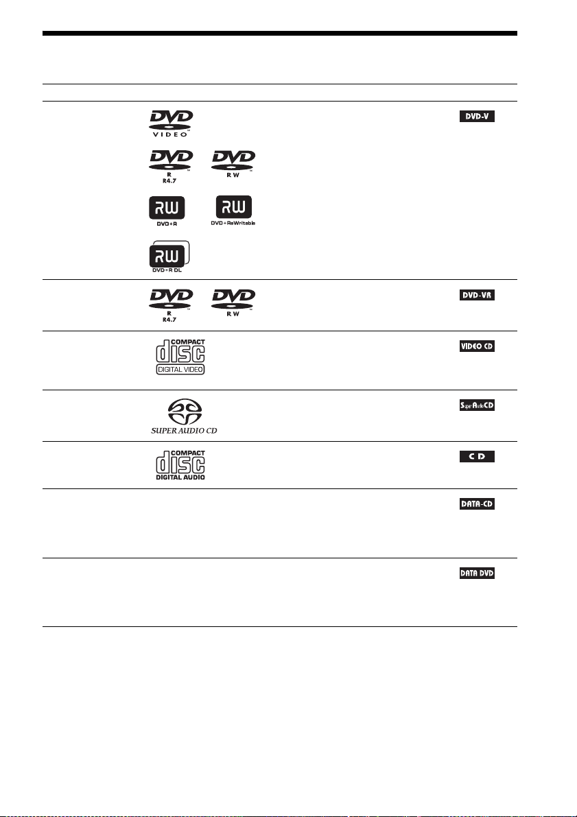
Playable Discs
Type Disc logo Characteristics Icon
DVD VIDEO • DVD VIDEO
• DVD-R/DVD-RW in DVD VIDEO
format or video mode
• DVD+R/DVD+RW in DVD VIDEO
format
VR (Video
Recording) mode
• DVD-R/DVD-RW in VR (Video
Recording) mode (except for DVD-R
DL)
VIDEO CD • VIDEO CD (Ver. 1.1 and 2.0 discs)
• Super VCD
• CD-R/CD-RW/CD-ROM in video CD
format or Super VCD format
Super Audio CD • Super Audio CD
CD • Audio CD
• CD-R/CD-RW in audio CD format
DATA CD – • CD-R/CD-RW/CD-ROM in DATA CD
format, containing MP3
image files
9660
2)
, and conforming to ISO
3)
Level 1/Level 2, or Joliet
files1) and JPEG
(extended format)
DATA DVD – • DVD-ROM/DVD-R/DVD-RW/
DVD+R/DVD+RW in DATA DVD
format, containing MP3 files1) and JPEG
image files2), and conforming to UDF
(Universal Disk Format)
1)
MP3 (MPEG1 Audio Layer 3) is a standard format defined by ISO/MPEG for compresses audio data. MP3 files
must be in MPEG1 Audio Layer 3 format.
2)
JPEG image files must conform to the DCF image file format. (DCF “Design rule for Camera File system”: Image
standards for digital cameras regulated by Japan Electronics and Information Technology Industries Association
(JEITA).)
3)
A logical format of files and folders on CD-ROMs, defined by ISO (International Organization for
Standardization).
US
7

Notes on discs
This product is designed to playback discs that conform to the Compact Disc (CD) standard.
DualDiscs and some of the music discs encoded with copyright protection technologies do not conform
to the Compact Disc (CD) standard, therefore, these discs may not be playable by this product.
Example of discs that the system cannot play
The system cannot play the following discs:
• CD-ROM/CD-R/CD-RW other than those recorded in the formats listed on page 7
• CD-ROM recorded in PHOTO CD format
• Data part of CD-Extra
• CD Graphics disc
• DVD Audio
• DATA CD/DATA DVD that does not contain MP3 files or JPEG image files
•DVD-RAM
•Blu-ray Disc
Also, the system cannot play the following discs:
• A DVD VIDEO with a different region code (page 9)
• A disc that has a non-standard shape (e.g., card, heart)
• A disc with paper or stickers on it
• A disc that has the adhesive of cellophane tape or a sticker still left on it
Note about CD-R/CD-RW/DVD-R/DVD-RW/DVD+R/DVD+RW
In some cases, CD-R/CD-RW/DVD-R/DVD-RW/DVD+R/DVD+RW cannot be played on this system
due to the recording quality or physical condition of the disc, or the characteristics of the recording
device and authoring software.
The disc will not play if it has not been correctly finalized. For more information, refer to the operating
instructions for the recording device.
Note that some playback functions may not work with some DVD+RWs/DVD+Rs, even if they have
been correctly finalized. In this case, view the disc by normal playback. Also some DATA CDs/DATA
DVDs created in Packet Write format cannot be played.
About Multi Session CD
• This system can play a Multi Session CD when an MP3 file is contained in the first session. Any
subsequent MP3 files recorded in later sessions can also be played back.
• This system can play a Multi Session CD when a JPEG image file is contained in the first session.
Any subsequent JPEG image files recorded in later sessions can also be played back.
• If MP3 files and JPEG image files in music CD format or video CD format are recorded in the first
session, only the first session will be played back.
US
8

Region code
Your system has a region code printed on the rear of the unit and will only play a DVD labeled with
the same region code.
A DVD VIDEO labeled will also play on this system.
If you try to play any other DVD VIDEO, the message [Playback prohibited by area limitations.] will
appear on the TV screen. Depending on the DVD VIDEO, no region code indication may be given even
though playing the DVD VIDEO is prohibited by area restrictions.
ALL
Note about playback operations of a DVD or VIDEO CD
Some playback operations on a DVD or VIDEO CD may be intentionally set by software producers.
Since this system will play a DVD or VIDEO CD according to the disc contents the software producers
designed, some playback features may not be available. Be sure to read the operating instructions
supplied with the DVD or VIDEO CD.
US
9

Getting Started
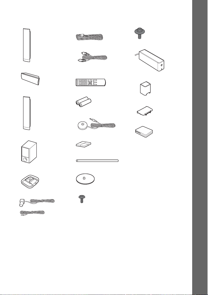
Unpacking
DAV-HDX589W
Getting Started
• Front speakers (2)
• Speaker cords (6, red/white/
green/gray/blue/purple)
• Screws (with washer) (4)
• Center speaker (1)
• Surround speakers (2)
• Subwoofer (1)
• AM loop antenna (aerial) (1)
• FM wire antenna (aerial) (1)
•Video cord (1)
• Remote commander
(remote) (1)
• R6 (size AA) batteries (2)
• Calibration mic (1)
• Foot pads (1 set)
•Posts (2)
• Bases (2)
• Surround amplifier (1)
• Speaker cord cover (1)
• Speaker cord holder (1)
• Wireless transceivers (2)
• Operating Instructions
• Quick Setup Guide
• Setup Disc (DVD)
• DIGITAL MEDIA PORT
adapter (TDM-iP20) (1)
10
or
US
• Screws (black) (4)
• Operating Instructions for
the DIGITAL MEDIA
PORT adapter (TDM-iP20)
DAV-HDX686W
• Front speakers (2)
• Center speaker (1)
• Surround speakers (2)
• Subwoofer (1)
• Speaker cords (6, red/white/
green/gray/blue/purple)
• Video cord (1)
• Remote commander
(remote) (1)
• R6 (size AA) batteries (2)
• Calibration mic (1)
• Foot pads (1 set)
• Posts (4)
• Screws (with washer) (8)
• Surround amplifier (1)
• Speaker cord cover (1)
• Speaker cord holder (1)
• Wireless transceivers (2)
• Operating Instructions
• Quick Setup Guide
• Setup Disc (DVD)
Getting Started
• AM loop antenna (aerial) (1)
• FM wire antenna (aerial) (1)
or
• Bases (4)
• Screws (black) (8)
11
US

Inserting batteries into the remote
Insert two R6 (size AA) batteries (supplied) by matching the 3 and # ends on the batteries to the
markings inside the compartment. To use the remote, point it at the remote sensor on the unit.
Getting Started
Note
• Do not leave the remote in an extremely hot or humid place.
• Do not use a new battery with an old one.
• Do not drop any foreign object into the remote casing, particularly when replacing the batteries.
• Do not expose the remote sensor to direct sunlight or lighting apparatus. Doing so may cause a malfunction.
• If you do not intend to use the remote for an extended period of time, remove the batteries to avoid possible damage
from battery leakage and corrosion.
12
US
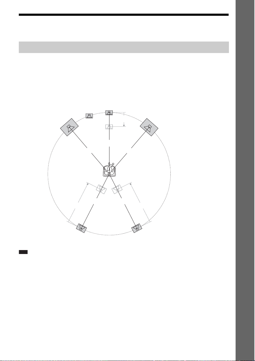
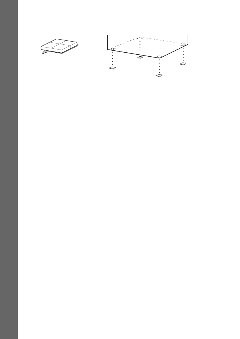
Step 1: Installing the System
Positioning the system
For the best possible surround sound, place all speakers at the same distance from the listening position
(A). The distance can be between 1.0 to 7.0 meters.
If you cannot place the center speaker and surround speakers at the same distance as (A), you can move
the center speaker up to 1.6 meters closer to the listening position (B), and the surround speakers up
to 5.0 meters closer to the listening position (C).
The subwoofer can be placed anywhere in the room.
Getting Started
Subwoofer
Front left speaker (L)
Center speaker
B
Front right speaker (R)
A
A
A
Surround left speaker (L)
Note
• Use caution when placing the speakers and/or speaker stands attached to the speakers on a specially treated (waxed,
oiled, polished, etc.) floor, as staining or discoloration may result.
• Do not lean or hang on a speaker, as it may fall down.
A
A
CC
Surround right speaker (R)
13
US
Attaching the foot pads to the subwoofer
Attach the foot pads (supplied) to the bottom of the subwoofer to stabilize the subwoofer and prevent
it from slipping.
,
Remove the foot pads from
Getting Started
the protective cover.
14
US

p
Assembling the speakers
Before connecting the speakers, attach the speaker stand to the speaker.
(For the front speakers of DAV-HDX589W, and the front and surround speakers of DAV-HDX686W)
Use the parts as follows:
DAV-HDX589W
• Front speakers (2)
• Speaker cords (2, red/white)
•Posts (2)
• Bases (2)
• Screws (black) (4)
• Screws (with washer) (4)
DAV-HDX686W
• Front and surround speakers (4)
• Speaker cords (4, red/white/blue/gray)
•Posts (4)
• Bases (4)
• Screws (black) (8)
• Screws (with washer) (8)
For details of how to connect the speaker cords to the SPEAKER jacks, see page 24.
Note
• Spread a cloth on the floor to avoid damaging the floor when you assemble the speakers.
Ti
• You can use the speaker without the speaker stand by installing it on the wall (page 21).
Getting Started
US
15
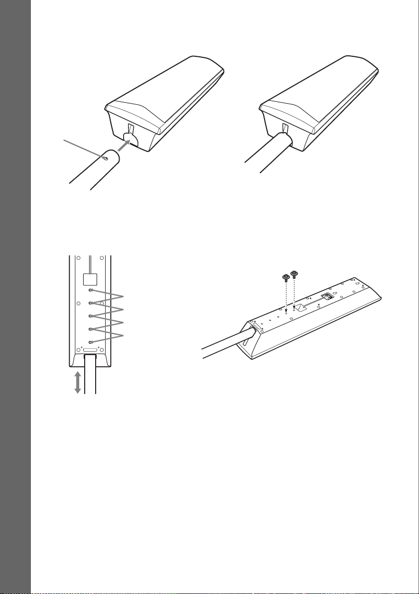
1 Insert the post into the hole on the bottom of the speaker so that the screw on the post
faces the front of the speaker.
Speaker
Getting Started
Screw
Post
,
2 Adjust the height of the speaker, then secure the post with two screws (with washer).
You can change the height of the speaker depending on the screw positions. Adjust the screw holes
of the post to the holes on the rear of the speaker (A, B, C, or D). The height of the speaker can
be increased by using the holes in order from A to D.
Rear of the speaker
A
B
C
D
Post
Example: Lowest position
Secure two screws (with
washer).
16
US
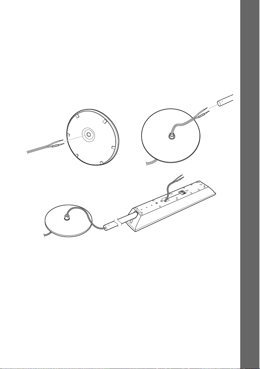
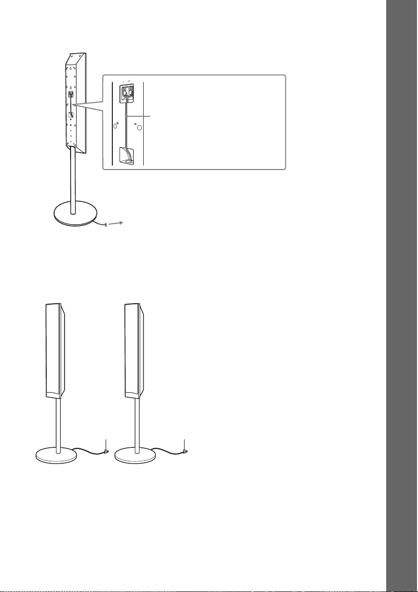
3 Thread the speaker cord through the hole in the base and post.
The connector and color tube of the speaker cords are the same color as the label of the jacks to be
connected.
Use the speaker cords as follows:
• Front left speaker (L): White
• Front right speaker (R): Red
• Surround left speaker (L): Blue (DAV-HDX686W only)
• Surround right speaker (R): Gray (DAV-HDX686W only)
Be careful with the orientation of the post. Thread the speaker cord into the end of the post that has
two holes.
Post
Bottom of the base
Top of the base
,
Speaker cord
,
Getting Started
Base
Rear of the speaker
17
US
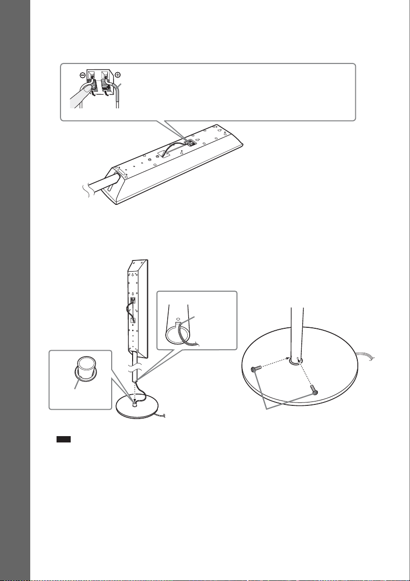
4 Connect the speaker cords to the speaker.
Be sure to match the speaker cords to the appropriate terminals on the speakers: the speaker cord
with the color tube to 3, and the speaker cord without the color tube to #.
Color tube
Front left speaker (L): White
Front right speaker (R): Red
Surround left speaker (L): Blue (DAV-HDX686W only)
Getting Started
Surround right speaker (R): Gray (DAV-HDX686W only)
Rear of the speaker
5 Attach the post to the base.
Insert the post so that the slot on the lower part of the post aligns with the projection of the base,
then secure the post with the two screws (black).
Post
Slot
,
Projection
Base
Note
• Make sure that the slot on the post aligns with the projection of the base by rotating the post slightly.
US
18
Screws
(black)
6 Take up any speaker cord slack.
Take up slack in the speaker cord by pulling from the bottom of the base.
Secure the speaker cord by running it
through the slot.
Adjust the length of the cord.
Fully-assembled illustration
DAV-HDX589W
Front left speaker (L):
White label
Front right speaker (R):
Red label
Getting Started
White
Red
19
US
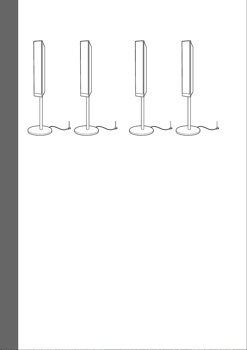
DAV-HDX686W
:
Front left speaker (L):
White label
Getting Started
Front right speaker (R):
Red label
Surround left speaker (L):
Blue label
Surround right speaker (R)
Gray label
White Red
Blue
Gray
20
US
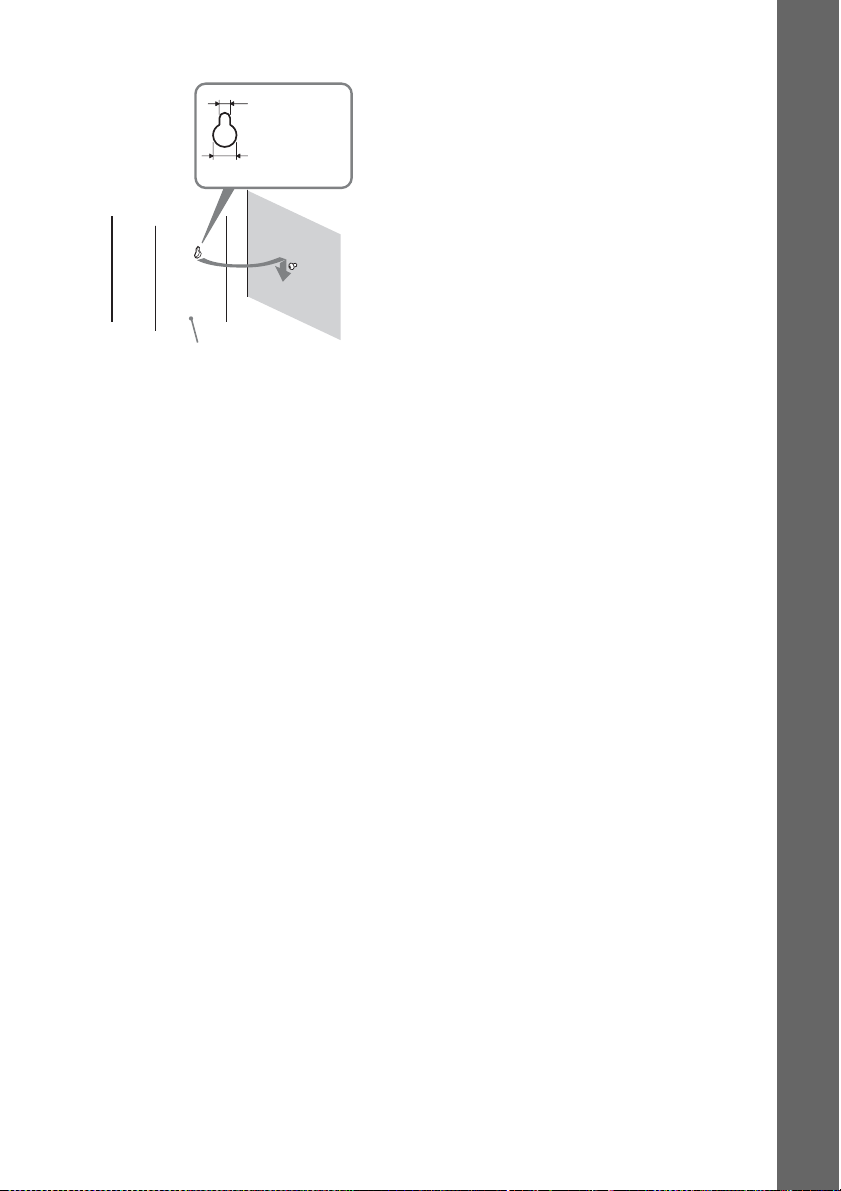
Installing the speakers on a wall
Caution
• Contact a screw shop or installer for information regarding the wall material or screws to be used.
• Use screws that are suitable for the wall material and strength. As a plaster board wall is especially fragile, attach
the screws securely to a beam. Install the speakers on a vertical and flat wall where reinforcement is applied.
• Sony is not responsible for accidents or damage caused by improper installation, insufficient wall strength or
improper screw installation, natural calamity, etc.
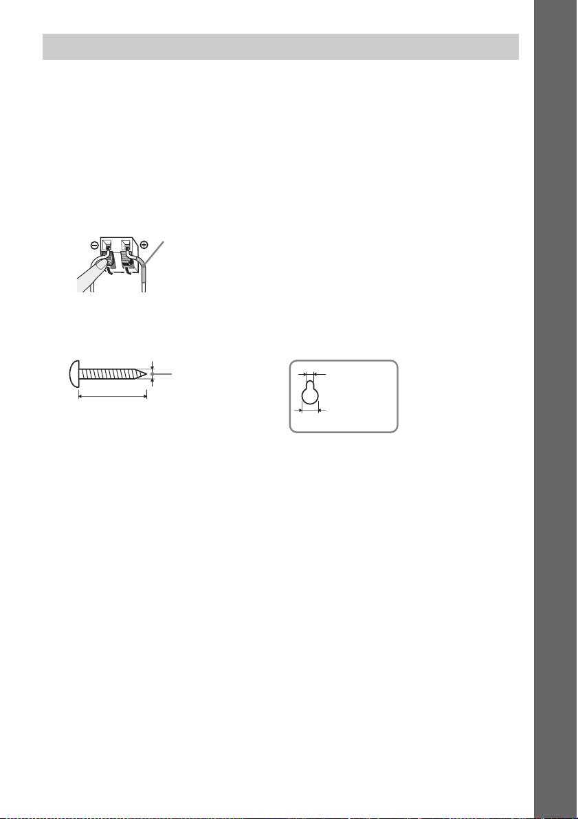
Before installing the speakers on a wall, connect the speaker cord to the speaker.
Be sure to match the speaker cords to the appropriate terminals on the speakers: the speaker cord with
the color tube to 3, and the speaker cord without the color tube to #.
Color tube
Front left speaker (L): White
Front right speaker (R): Red
Center speaker: Green
Surround left speaker (L): Blue
Surround right speaker (R): Gray
1 Prepare screws (not supplied) that are suitable for the hole on the back of each speaker.
See the illustrations below.
Getting Started
30 mm (1 3/16 inches)
4 mm (
5
/32 inch)
5 mm
7
/32 inch)
(
10 mm
13
/32 inch)
(
Hole on the back of
the speaker
21
US
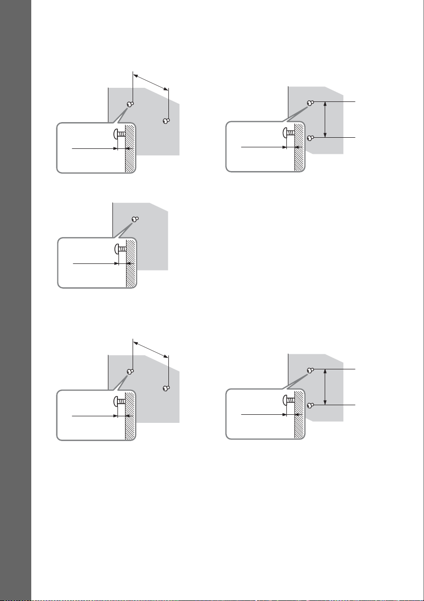
2 Fasten the screws to the wall.
DAV-HDX589W
For the center speaker
145 mm
(5
3
/4 inches)
For the front speakers
Getting Started
8 to 10 mm
11
/32 to 13/32
(
For the surround speakers
11
/32 to 13/32
(
inch
8 to 10 mm
inch
)
)
DAV-HDX686W
For the center speaker
145 mm
3
/4 inches)
(5
8 to 10 mm
11
(
/32 to 13/32
For the other speakers
inch
)
101.6 mm
4 inches
(
101.6 mm
(
4 inches
)
)
22
US
11
/32 to 13/32
(
8 to 10 mm
inch
8 to 10 mm
11
(
)
/32 to 13/32
inch
)
3 Hang the speakers on the screws.
5 mm
7
/32 inch)
(
10 mm
13
/32 inch)
(
Rear of the speaker
Hole on the back of
the speaker
Getting Started
23
US
Step 2: Connecting the System
For connecting the system, read the information on the following pages.
Do not connect the AC power cord (mains lead) of the unit to a wall outlet (mains) until all the other
connections are made.
Note
• When you connect another component with a volume control, turn down the volume of the other components to a
Getting Started
level where sound is not distorted.
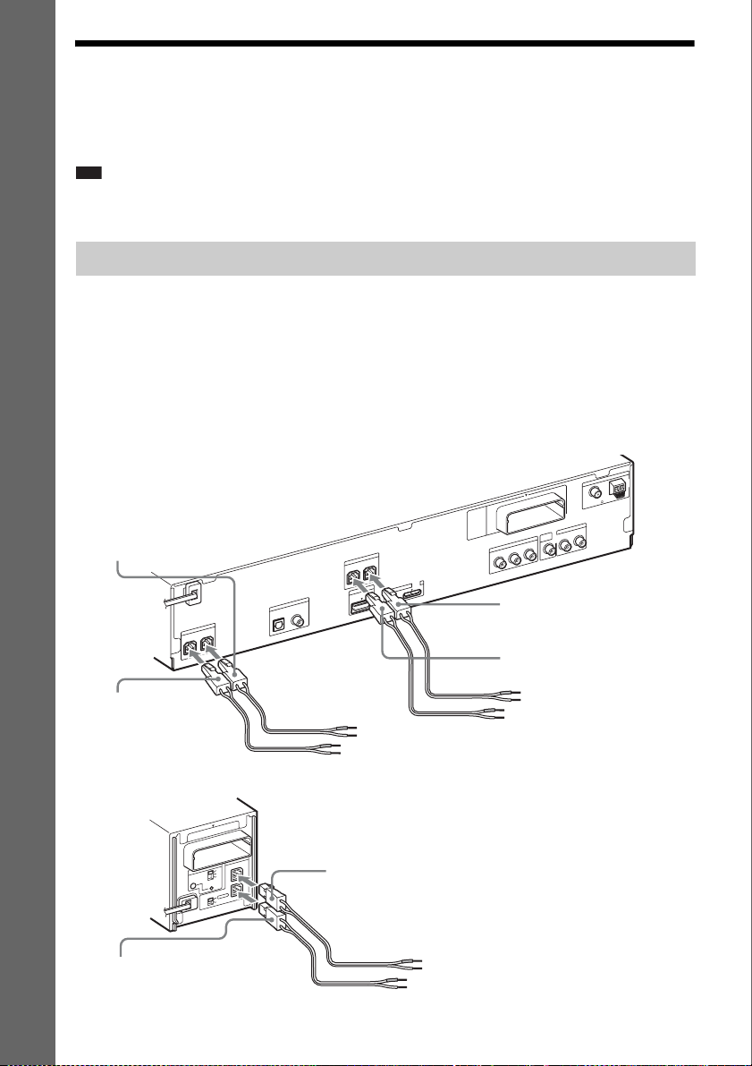
Connecting the speakers
The connector of the speaker cords and the color tube are color-coded depending on the type of speaker.
Connect the speaker cords to match the color of the SPEAKER jacks of the unit.
Be sure to match the speaker cords to the appropriate terminals on the speakers: the speaker cord with
the color tube to 3, and the speaker cord without the color tube to #. Do not catch the speaker cord
insulation (rubber covering) in the speaker terminals.
To connect speaker cords to the unit
When connecting to the unit, insert the connector until it clicks.
Rear panel of the unit
Purple
(Subwoofer)
CENTER
0
1
T
-R
W
Z
E
R
E
K
A
E
P
S
FRONT L
V
T
DIGITAL IN
R
E
K
A
E
P
S
R
E
F
O
O
W
B
U
S
COAXIALOPTICAL
FRONT R
T
T
R
U
O
P
I O
M
M
D
D
H
V
5
C
D
X
A
M
A
.7
0
VIDEO
OUT
T
U
O
O
E
D
I
V
T
N
E
N
O
P
M
O
C
R
/C
R
P
B
/C
B
P
Y
White
(Front left speaker (L))
Red
(Front right speaker (R))
A
N
N
E
T
N
A
FM
COAXIAL 75
TV/VIDEO
L
AUDIO IN
R
AM
Green
(Center speaker)
Rear panel of the surround amplifier
10
T
R
-
W
Z
E
A
E
P
S
ID
IR
A
-A
S
B
C
RING
PAI
R
O
T
C
E
L
E
S
D
D
N
N
U
U
O
R
O
R
R
U
S
R
U
D
S
N
U
O
R
R
U
S
K
C
A
B
Gray
(Surround right speaker (R))
US
24
R
E
K
L
R
Blue
(Surround left speaker (L))
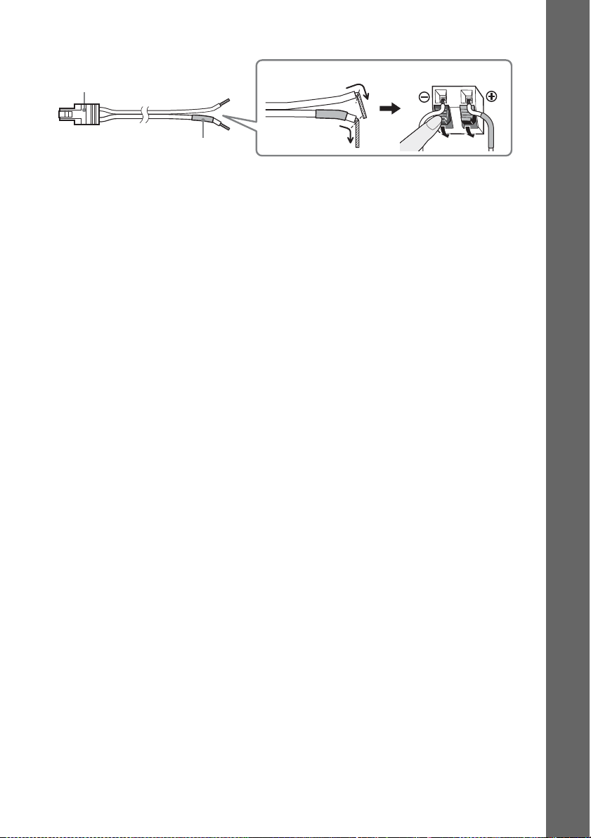
To connect speaker cords to the speaker
Connector
Color tube
(–)
(+)
Rear of the speaker
Getting Started
25
US
Connecting the TV (Video connection)
This connection sends a video signal to the TV.
Depending on the jacks on your TV, select the connection method.
A
N
N
E
T
N
A
AM
FM
COAXIAL 75
TV/VIDEO
L
AUDIO IN
R
A Video cord (supplied)
Getting Started
C Component video cable
(not supplied)
0
1
T
R
-
W
Z
E
R
E
K
A
E
P
S
FRONT L
FRONT R
T
T
R
U
O
P
I O
M
M
D
D
H
V
5
C
D
X
A
M
A
.7
V
T
DIGITAL IN
R
E
K
A
E
P
S
R
E
F
O
O
W
B
U
S
CENTER
COAXIALOPTICAL
0
VIDEO
OUT
T
U
O
O
E
D
I
V
T
N
E
N
O
P
M
O
C
R
/C
R
P
B
/C
B
P
Y
B HDMI cable (not supplied)
To the HDMI IN jack
of the TV.
To the component
video input jacks of
the TV.
To the video input jack of
the TV.
Method 1: Video cord (A) connection
This is the basic connection.
Method 2: HDMI* cable (B) and video cord (A) connection
If your TV has an HDMI jack, connect to the TV both with an HDMI cable and video cord. Picture
quality will be improved compared to using only the video cord connection.
When connecting with the HDMI cable, you need to select the type of output signal (page 37).
To view images from the DIGITAL MEDIA PORT adapter, you need to connect to the TV with the
video cord. Video signals from the DIGITAL MEDIA PORT adapter are not output via the HDMI OUT
jack.
* HDMI (High-Definition Multimedia Interface)
Method 3: Component video cable (C) and video cord (A) connection
If your TV does not have an HDMI jack, but has component video input jacks, connect to the TV both
with a component video cable and video cord. Picture quality will be improved compared to using only
the video cord connection.
When connecting with the component video cable, you need to set the type of output signal to
progressive format (page 37).
To view images from the DIGITAL MEDIA PORT adapter, you need to connect to the TV with the
video cord. Video signals from the DIGITAL MEDIA PORT adapter are not output via the
COMPONENT VIDEO OUT jack.
US
26
p
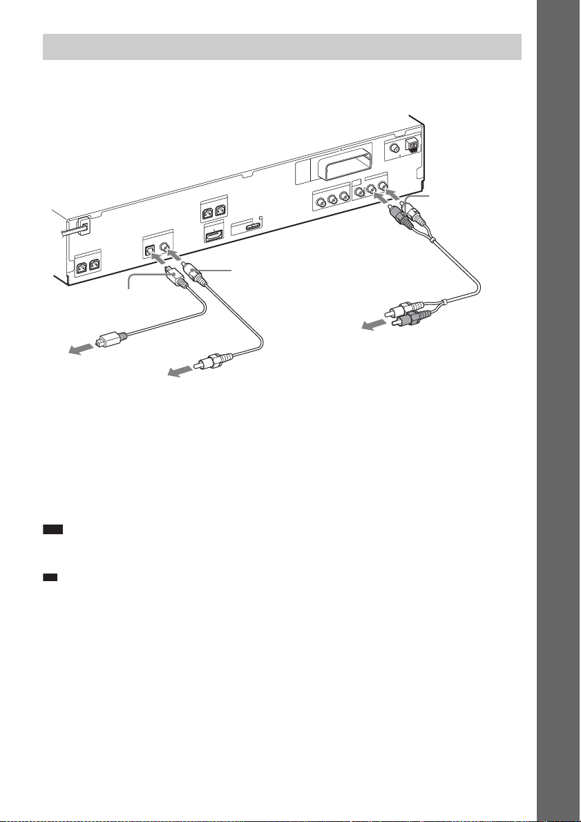
Connecting the TV (Audio connection)
This connection sends an audio signal to the unit from the TV. To listen to TV sound via the system,
perform this connection.
A
N
N
E
T
N
A
AM
FM
0
1
T
R
-
W
Z
E
M
O
R
E
K
A
E
P
S
FRONT L
FRONT R
T
T
R
U
O
P
I O
M
M
D
D
H
V
5
C
D
X
A
M
A
.7
V
T
DIGITAL IN
R
E
K
A
E
P
S
R
FE
O
O
W
B
U
S
CENTER
COAXIALOPTICAL
0
F Digital coaxial cord (not
supplied)
C
Y
E Digital optical cord
(not supplied)
To the digital optical out
jack of the TV.
To the digital coaxial out jack of
the TV.
Method 1: Audio cord (D) connection
This is the basic connection and sends an analog audio signal.
T
U
O
O
E
D
I
V
T
N
E
N
O
P
R
/C
R
P
B
/C
B
P
COAXIAL 75
TV/VIDEO
VIDEO
OUT
L
AUDIO IN
R
D Audio cord (not
supplied)
To the audio out jacks of
the TV.
Getting Started
Method 2: Digital optical cord (E) or digital coaxial cord (F) connection
When the TV has a digital optical or coaxial output jack, you can improve sound quality by connecting
with a digital optical or coaxial cord in addition to an audio cord connection.
Note
• The system can accept both digital and analog signals. Digital signals have priority over analog signals. (COAXIAL
has priority over OPTICAL.) If the digital signal ceases, the analog signal will be processed after 2 seconds.
Ti
• You can connect another component, such as a VCR, digital satellite receiver, or PlayStation, to the TV/VIDEO
(AUDIO IN R/L) jacks or DIGITAL IN OPTICAL/COAXIAL jacks instead of the TV.
27
US
p
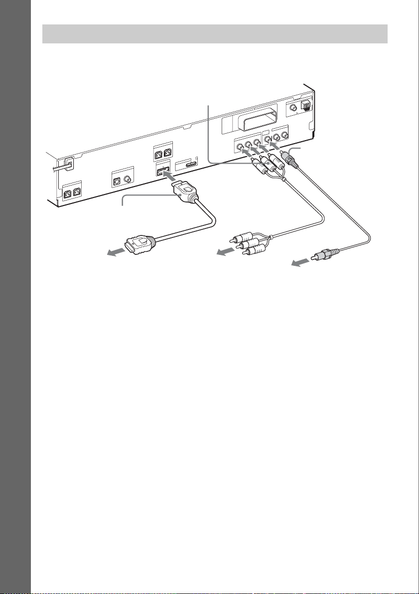
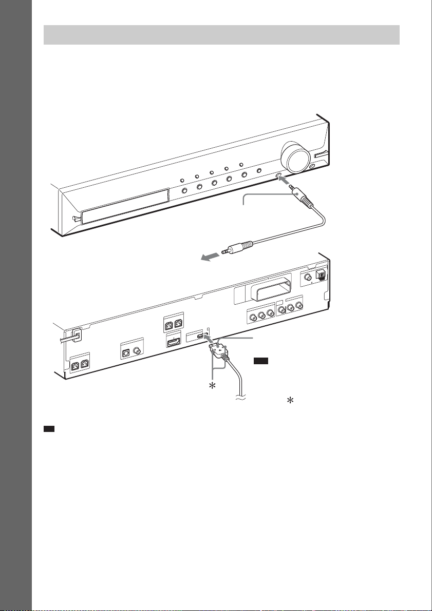
Connecting the other components
You can enjoy connected components via the system’s speakers.
Portable audio source (not supplied): G
DIGITAL MEDIA PORT adapter: H (TDM-iP20 is supplied with U.S. models. You can also use other
DIGITAL MEDIA PORT adapters.)
Getting Started
G Stereo mini-plug cord
(not supplied)
A
N
N
E
T
To a portable audio source
0
1
T
R
-
W
Z
E
R
E
K
A
E
P
S
FRONT L
V
T
DIGITAL IN
R
E
K
A
E
P
S
R
E
F
O
O
W
B
U
S
CENTER
COAXIALOPTICAL
FRONT R
T
T
R
U
O
P
I O
M
M
D
D
H
V
5
C
D
X
A
M
A
.7
0
VIDEO
OUT
T
U
O
O
E
D
I
V
T
N
E
N
O
P
M
O
C
R
/C
R
P
B
/C
B
P
Y
H DIGITAL MEDIA PORT
adapter (page 72)
Note
• Connect the DIGITAL MEDIA PORT
adapter so that the V marks are aligned.
When disconnecting, pull out while
pressing .
N
A
AM
FM
COAXIAL 75
TV/VIDEO
L
AUDIO IN
R
Ti
• You can connect another component, such as a VCR, digital satellite receiver, or PlayStation, to the TV/VIDEO
(AUDIO IN R/L) jacks or DIGITAL IN OPTICAL/COAXIAL jacks instead of the TV.
US
28
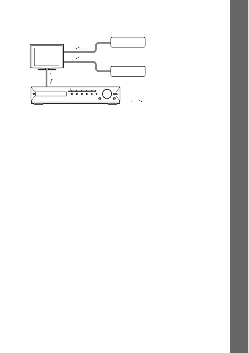
If your TV has multiple audio/video inputs
You can enjoy sound with the speakers of the system through the connected TV. Connect the
components as follows.
TV
System
VCR, digital satellite receiver,
PlayStation, etc.
VCR, digital satellite receiver,
PlayStation, etc.
:Signal flow
Select the component on the TV. For details, refer to the operating instructions of the TV.
If the TV does not have multiple audio/video inputs, a switcher will be necessary to receive sound from
more than one component.
Getting Started
29
US
p
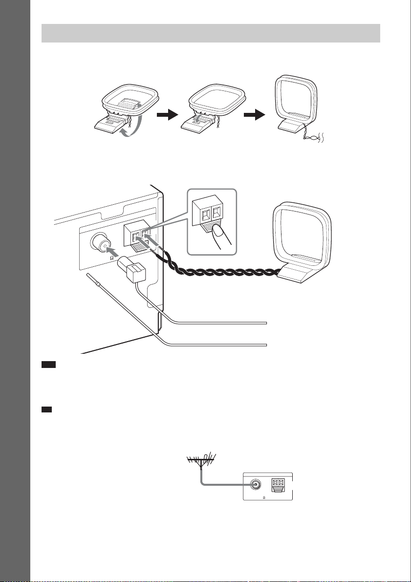
Connecting the antenna (aerial)
To assemble the AM loop antenna (aerial)
Getting Started
To connect the antenna (aerial)
A
N
N
E
T
N
A
FM
COAXIAL 75
AM
or
AM
AM loop antenna (aerial)
(supplied)
FM wire antenna (aerial)
(supplied)
Note
• Keep the AM loop antenna (aerial) and cord away from the system or other AV components, as noise may result.
• Be sure to fully extend the FM wire antenna (aerial).
• After connecting the FM wire antenna (aerial), keep it as horizontal as possible.
Ti
• Adjust the direction of the AM loop antenna (aerial) for best AM broadcast sound.
• If you have poor FM reception, use a 75-ohm coaxial cable (not supplied) to connect the unit to an outdoor FM
antenna (aerial) as shown below.
Outdoor FM antenna (aerial)
US
30
Unit
FM
COAXIAL 75
ANTENNA
AM
 Loading...