

Sony DAV-FXG99K Operating Instructions Manual
3-283-049-11(1)
DVD Home Theatre
System
Operating Instructions
DAV-FXG99K
©2008 Sony Corporation
WARNING
To reduce the risk of fire or electric
shock, do not expose this apparatus to
rain or moisture.
Do not install the appliance in a confined space, such
as a bookcase or built-in cabinet.
To prevent fire, do not cover the ventilation of the
apparatus with news papers, table-cloths, curtains, etc.
And don’t place lighted candles on the apparatus.
To prevent fire or shock hazard, do not place objects
filled with liquids, such as vases, on the apparatus.
Batteries or batteries installed apparatus shall not be
exposed to excessive heat such as sunshine, fire or the
like.
In door use only.
This appliance is
classified as a CLASS 1
LASER product. This
marking is loca ted on the
rear exterior.
RISK OF ELECTRIC SHOCK DO NOT
OPEN
No operator serviceable parts inside. Refer servicing to
qualified personnel.
To avoid electrical shock, do not open the cabinet.
Refer servicing to qualified personnel only.
About This Operating Instructions
• The instructions in this Operating Instructions
describe the controls on the remote. You can
also use the controls on the unit if they have the
same or similar names as those on the remote.
• The Control Menu items may vary depending
on the area.
• “DVD” may be used as a general term for a
DVD VIDEO, DVD+RW/DVD+R, and DVDRW/DVD-R.
• Measurements are expressed in feet (ft) for
North American models.
• The default setting is underlined.
Precautions
On power sources
• AC power cord (mains lead) must be changed only at
the qualified service shop.
• The unit is not disconnected from the AC power
source (mains) as long as it is connected to the wall
outlet (mains), even if the unit itself has been turned
off.
• Install this system so that the AC power cord (mains
lead) can be unplugged from the wall socket
immediately in the event of trouble.
GB
2

Table of Contents
About This Operating Instructions..........2
Playable Discs......................................... 4
Getting Started
Step 1: Assembling
the Speakers ............................. 9
Step 2: Positioning the System... 15
Step 3: Connecting the System... 18
Step 4: Performing the Quick
Setup........................................ 26
Step 5: Enjoying Sound from all the
Speakers.................................. 29
Sound Adjustment
Enjoying Surround Sound by Using
Decoding Mode ..............................31
Selecting the Sound Mode .................... 33
Enjoying Multiplex Broadcast Sound ... 34
Disc
Playing a Disc ....................................... 35
Using Play Mode...................................40
Searching/Selecting a Disc ...................43
Playing MP3 Files/JPEG Image Files... 45
Enjoying DivX® Videos....................... 48
Adjusting the Delay Between the Picture
and Sound .......................................50
Restricting Playback of the Disc...........51
Using the Setup Display........................53
Tuner
Presetting Radio Stations......................62
Listening to the Radio...........................63
Control for HDMI/External
Audio Device
Using the Control for HDMI Function for
“BRAVIA” Sync ............................65
Playing Back Audio Files/JPEG Image
Files of a USB Device ....................68
Storing Songs in a USB Device............74
Using the DIGITAL MEDIA PORT
Adapter ........................................... 77
Other Operations
Getting Optimal Surround Sound for a
Room .............................................. 78
Calibrating the Appropriate Settings
Automatically................................. 79
Controlling the TV with the Supplied
Remote ........................................... 80
Enjoying Karaoke................................. 82
Using the Sound Effect......................... 86
Using the Sleep Timer .......................... 86
Changing the Brightness of the Front
Panel Display.................................. 87
Viewing Information About the Disc ... 87
Returning to the Default Settings ......... 90
Additional Information
Precautions............................................ 91
Notes about the Discs ........................... 92
Troubleshooting.................................... 93
Self-diagnosis Function ...................... 102
Specifications...................................... 103
Glossary.............................................. 104
Language Code List ............................ 107
Index to Parts and Control .................. 108
Guide to the Control Menu Display ... 112
Index ................................................... 116
GB
3
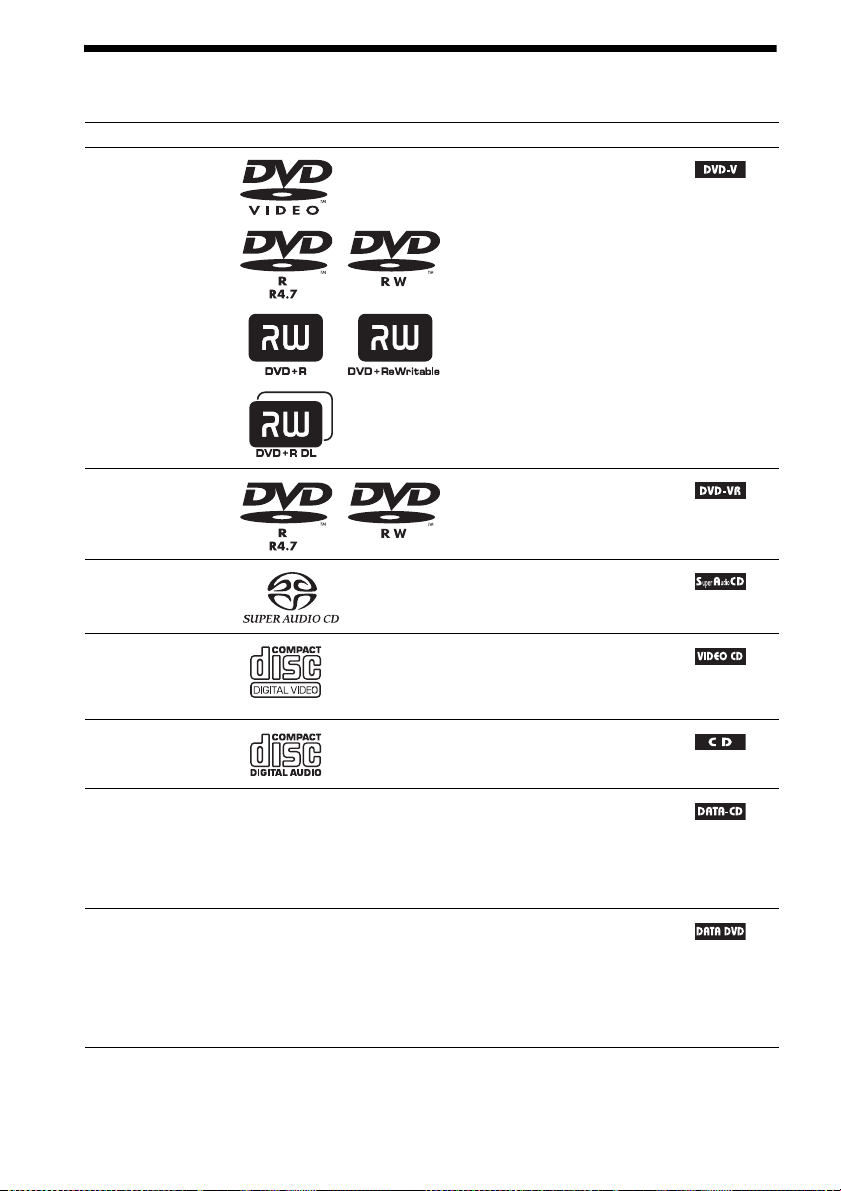
Playable Discs
Type Disc logo Characteristics Icon
DVD VIDEO • DVD VIDEO
• DVD-R/DVD-RW in DVD
VIDEO format or video mode
• DVD+R/DVD+RW in DVD
VIDEO format
VR (Video
Recording) mode
• DVD-R/DVD-RW in VR (Video
Recording) mode (except for
DVD-R DL)
Super Audio CD • Super Audio CD
VIDEO CD • VIDEO CD (Ver. 1.1 and 2.0 discs)
• Super VCD
• CD-R/CD-RW/CD-ROM in video
CD format or Super VCD format
CD • Audio CD
• CD-R/CD-RW in audio CD format
DATA CD – • CD-R/CD-RW/CD-ROM in
DATA CD format, containing MP3
files1), JPEG image files2), and
DivX video files
conforming to ISO 9660
3)4)
, and
5)
Level 1/
Level 2, or Joliet (extended format)
DATA DVD – • DVD-ROM/DVD-R/DVD-RW/
DVD+R/DVD+RW in DATA
DVD format, containing MP3
files1), JPEG image files2), and
DivX video files
3)4)
, and
conforming to UDF (Universal
Disk Format)
1)
MP3 (MPEG1 Audio Layer 3) is a standard format defined by ISO/MPEG which compresses audio data. MP3 files
must be in MPEG1 Audio Layer 3 format.
GB
4

2)
JPEG image files must conform to the DCF image file format. (DCF “Design rule for Camera File system”: Image
standards for digital cameras regulated by Japan Electronics and Information Technology Industries Association
(JEITA).)
3)
DivX® is a video file compression technology, developed by DivX, Inc.
4)
DivX, DivX Certified, and associated logos are trademarks of DivX, Inc. and are used under license.
5)
A logical format of files and folders on CD-ROMs, defined by ISO (International Organization for
Standardization).
“DVD-RW,” “DVD+RW,” “DVD+R,”“DVD VIDEO,” and the “CD” logos are trademarks.
Example of discs that the system cannot play
The system cannot play the following discs:
• CD-ROM/CD-R/CD-RW other than those recorded in the formats listed on page 4
• CD-ROM recorded in PHOTO CD format
• Data part of CD-Extra
• CD Graphics disc
• DVD Audio
• DATA DVD that does not contain MP3 files, JPEG image files, or DivX video files
• DVD-RAM
Also, the system cannot play the following discs:
• A DVD VIDEO with a different region code (page 6)
• A disc that has a non-standard shape (e.g., card, heart)
• A disc with paper or stickers on it
• A disc that has the adhesive of cellophane tape or a sticker still left on it
Note about CD-R/CD-RW/DVD-R/DVD-RW/DVD+R/DVD+RW
In some c ases, CD-R/CD-RW/DVD-R /DVD-RW/DVD+R /DVD+RW cannot be played on th is system
due to the recording quality or physical condition of the disc, or the characteristics of the recording
device and authoring software.
The disc will not play if it has not been correctly finalized. For more information, refer to the operating
instructions for the recording device.
Note that some playback functions may not work with some DVD+RWs/DVD+Rs, even if they have
been correctly finalized. In this case, view the disc by normal playback. Also some DATA CDs/DATA
DVDs created in Packet Write format cannot be played.
Music discs encoded with copyright protection technologies
This product is designed to play back discs that conform to the Compact Disc (CD) standard.
Recently, various music discs encoded with copyright protection technologies are marketed by some
record companies. Please be aware that among those discs, there are some that do not conform to the
CD standard and may not be playable by this product.
Note on DualDiscs
A DualDisc is a two sided disc product which mates DVD recorded material on one side with digital
audio material on the other side. However, since the audio material side does not conform to the
Compact Disc (CD) standard, playback on this product is not guaranteed.
GB
5
About Multi Session CD
• This system can play a Multi Session CD when an MP3 file is contained in the first session. Any
subsequent MP3 files recorded in later sessions can also be played back.
• This system can play a Multi Session CD when a JPEG image file is contained in the first session.
Any subsequent JPEG image files recorded in later sessions can also be played back.
• If MP3 files and JPEG image files in music CD format or video CD format are recorded in the first
session, only the first session will be played back.
Region code
Your system has a region code printed on the rear of the unit and will only play a DVD labeled with
the same region code.
A DVD VIDEO labeled will also play on this system.
If you try to play any other DVD VIDEO, the message [Playback prohibited by area limitations.] will
appear on the TV screen. Depending on the DVD VIDEO, no region code indication may be given even
though playing the DVD VIDEO is prohibited by area restrictions.
ALL
Note about playback operations of a DVD or VIDEO CD
Some playback operations on a DVD or VIDEO CD may be intentionally set by software producers.
Since this system will play a DVD or VIDEO CD according to the disc contents the software producers
designed, some playback features may not be available. Be sure to read the operating instructions
supplied with the DVD or VIDEO CD.
Copyrights
This product incorporates copyright protection technology that is protected by U.S. patents and other
intellectual property rights. Use of this copyright protection technology must be authorized by
Macrovision, and is intended for home and other limited viewing uses only unless otherwise authorized
by Macrovision. Reverse engineering or disassembly is prohibited.
This system incorporates with Dolby* Digital and Dolby Pro Logic (II) adaptive matrix surround
decoder and the DTS** Digital Surround System.
* Manufactured under license from Dolby Laboratories.
“Dolby”, “Pro Logic”, and the double-D symbol are trademarks of Dolby Laboratories.
** Manufactured under license from DTS, Inc.
“DTS” and “DTS Digital Surround” are registered trademarks of DTS, Inc.
This system incorporates High-Definition Multimedia Interface (HDMITM) technology.
HDMI, the HDMI logo and High-Definition Multimedia Interface are trademarks or registered
trademarks of HDMI Licensing LLC.
“BRAVIA” and are trademarks of Sony Corporation.
GB
6
Getting Started
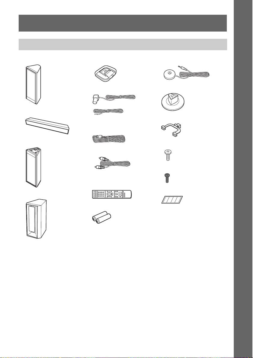
Unpacking
Getting Started
• Front speakers (2)
• Center speaker (1)
• Surround speakers (2)
• Subwoofer (1)
• AM loop antenna (aerial) (1)
• FM wire antenna (aerial) (1)
or
• Speaker cords (6, red/white/
green/gray/blue/purple)
• Video cord (1)
• Remote commander
(remote) (1)
• R6 (size AA) batteries (2)
• Calibration mic (1)
• Stand bases (2)
•Clampers (2)
• Screws (silver) (4)
• Screws (black) (2)
•Tape (1 set)
• Operating Instructions
• Speaker and TV co nnections
(card)
GB
7
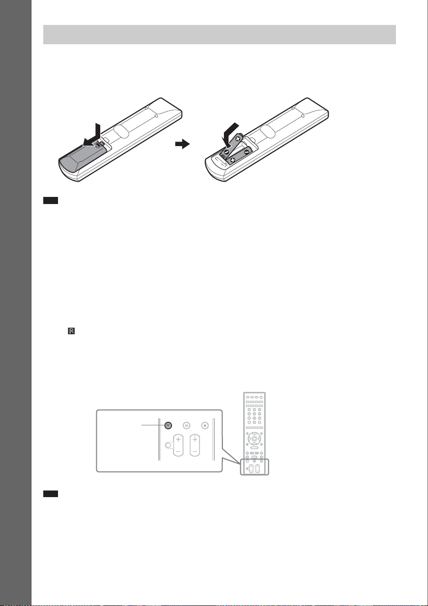
Using the remote
Inserting batteries into the remote
Insert two R6 (size AA) batteries (supplied) by matching the 3 and # ends on the batteries to the
markings inside the compartment.
Getting Started
Note
• Do not leave the remote in an extremely hot or humid place.
• Do not use a new battery with an old one.
• Do not drop any foreign object into the remote casing, particularly when replacing the batteries.
• If you do not intend to use the remote for an extended period of time, remove the batteries to avoid possible damage
from battery leakage and corrosion.
About operation of the remote
You can operate this system and TV using the supplied remote.
x System operation
Press TV so that TV flashes four times.
The remote enters system operation mode. When operating the system, point the remote at the remote
sensor on the unit.
x TV operation
Press TV so that TV lights up for 1 second.
The remote enters the TV mode. To operate the system, point the remote at the TV. For details, see
“Controlling the TV with the Supplied Remote” (page 80).
TV
Note
• Do not expose the remote sensor to direct sunlight or lighting apparatus. Doing so may cause a malfunction.
GB
8
Step 1: Assembling the Speakers
Before connecting the speakers, attach the speaker stand to the speaker.
(For the front and surround speakers)
Use the parts as follows:
• Front and surround speakers (4)
• Speaker cords (4, red/white/blue/gray)
• Stand bases (2)
• Clampers (2)
• Screws (silver) (4)
• Screws (black) (2)
About how to connect the speaker cords to the SPEAKER jacks, see page 19.
Note
• Spread a cloth on the floor to avoid damaging the floor when you assemble the speakers.
• Since the speakers are heavy, it is recommended that at least 2 people assemble the speakers.
Standard assembly
You have the option to choose from a range of stands (not supplied) if desired, according to your
installation. This manual shows the standard assembly, using the supplied speaker stands.
The front speakers are labeled “FRONT L” and “FRONT R.” The surround speakers are labeled “SUR
L” and “SUR R.”
Front speaker (R)
“FRONT R”
Front speaker (L)
“FRONT L”
Getting Started
Surround speaker (L)
“SUR L”
Surround speaker (R)
“SUR R”
GB
9
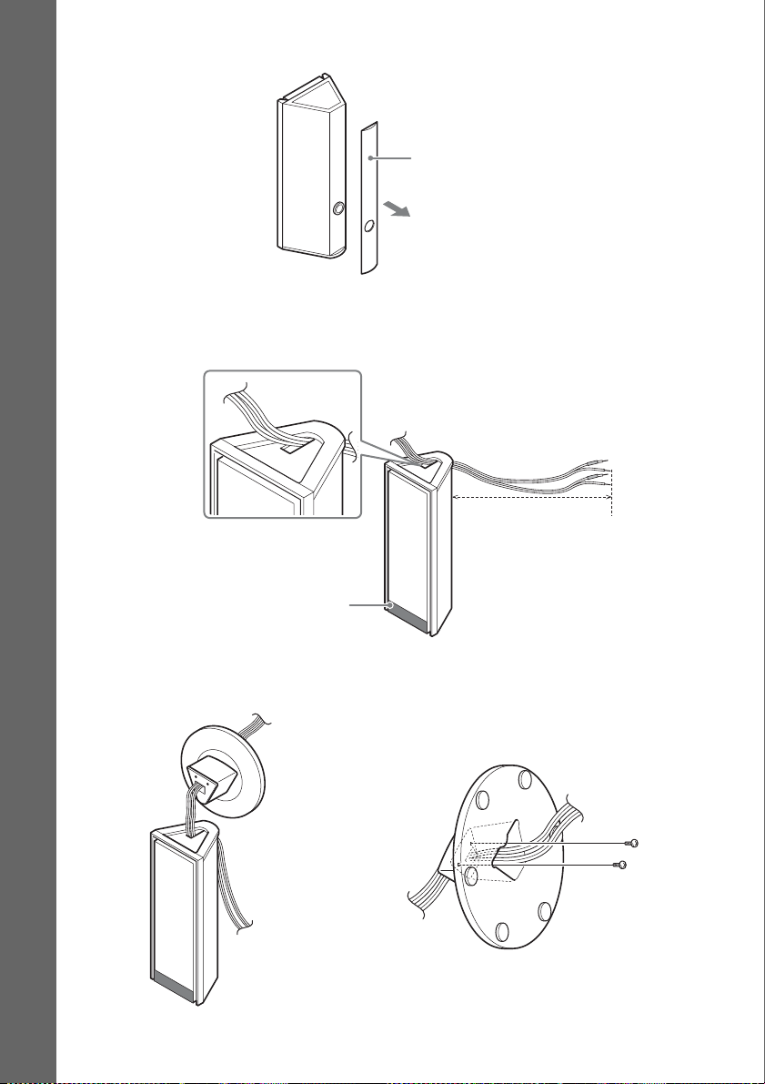
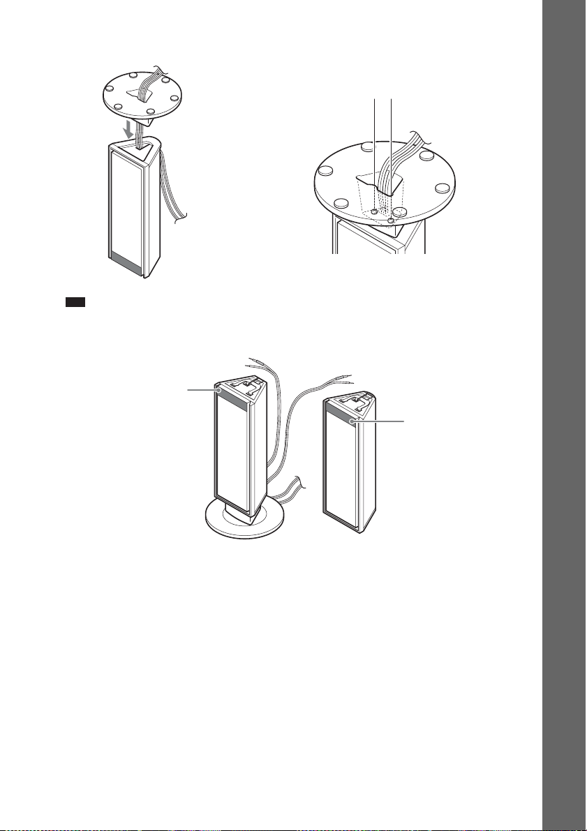
1 Remove the rear panel of the surround speaker.
Rear panel
Getting Started
2 Turn the surround speaker upside down, and thread the 2 speaker cords through.
The white and blue speaker cords are for the surround speaker (L) labeled “SUR L.” The red and
grey speaker cords are for the surround speaker (R) labeled “SUR R.”
About 800 mm
This side down.
Surround speaker
3 Thread the speaker cords through, and set the screws (silver) in the screw holes of the
stand base.
Screws (silver)
,
Stand base
GB
10
4 Attach the stand base, and secure with the screws.
Stand base
,
Note
• Do not catch the speaker cords between the surround speaker and the stand base.
5 Turn the surround and front speakers upside down.
This side up.
Surround speaker
Secure the stand base with
the screws.
This side up.
Getting Started
Front speaker
11
GB
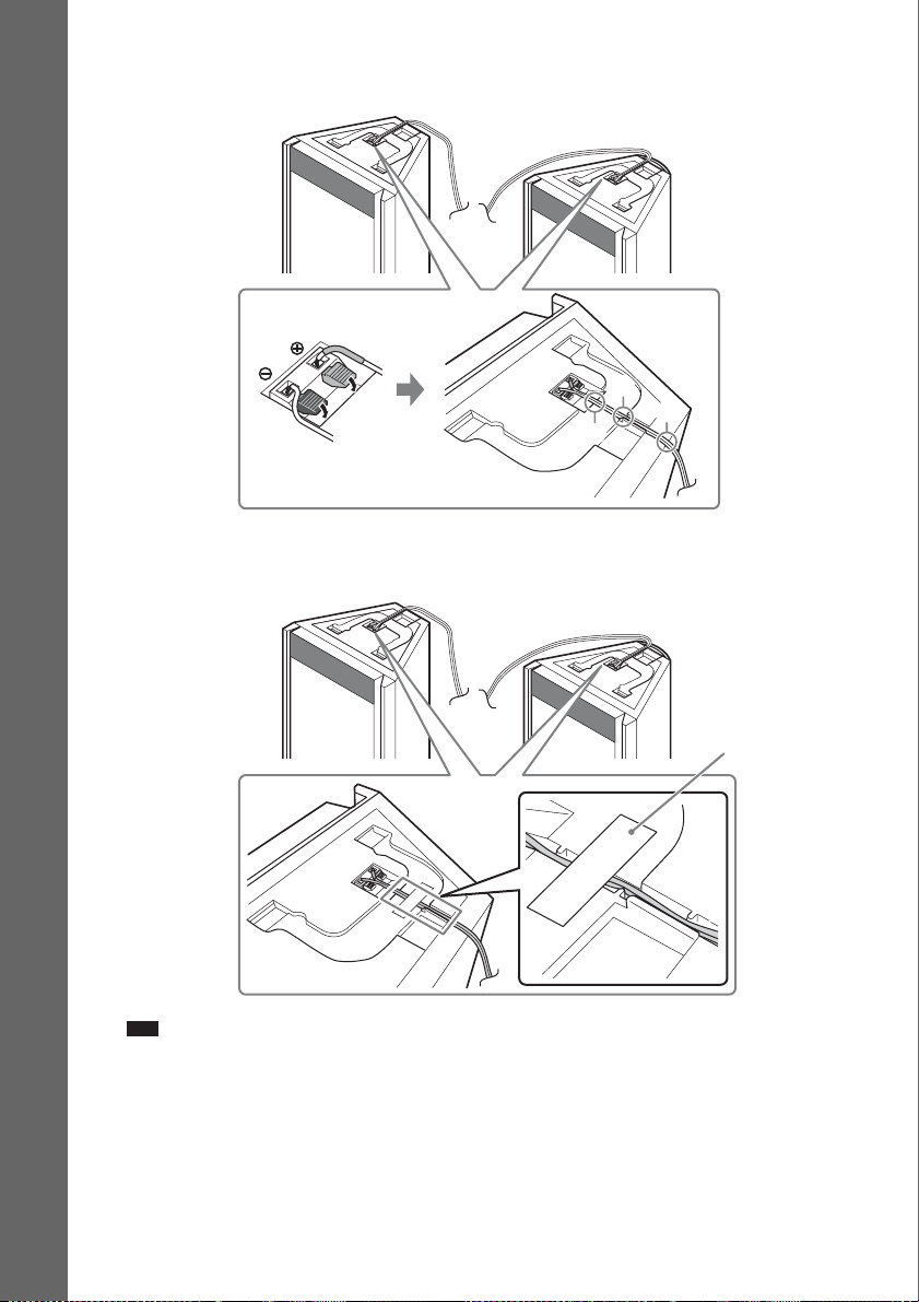
6 Connect the speaker cords observing their color coding, then run them through the
slots (A, B, and C) all the way.
Surround speaker
Front speaker
Getting Started
B
C
A
7 Remove the tape (supplied) from the mount seat, then attach the tape to each speaker
to prevent the cords coming out.
Surround speaker
Front speaker
Note
• Make sure that the tape is attached smoothly.
GB
12
Tape

8 Attach the clamper to the surround speaker.
Clamper
Surround speaker
Front speaker
Note
• Do not push the clamper until the front speaker has been placed on top.
9 Attach the front speaker squarely on the surround speaker, carefully aligning their
enclosures.
After attaching, make sure that the front speaker and the surround speaker are securely attached.
Front speaker
Getting Started
Surround speaker
13
GB
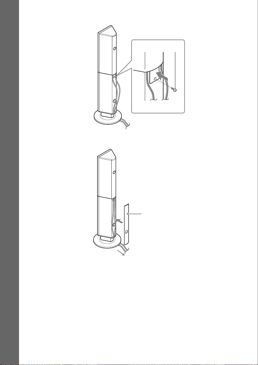
10 Push in the clamper carefully, then secure with the screw (black).
Screw (black)
Getting Started
11 Adjust the speaker cords, and retouch the rear panel.
14
Rear panel
Adjust the length of the speaker cords.
GB
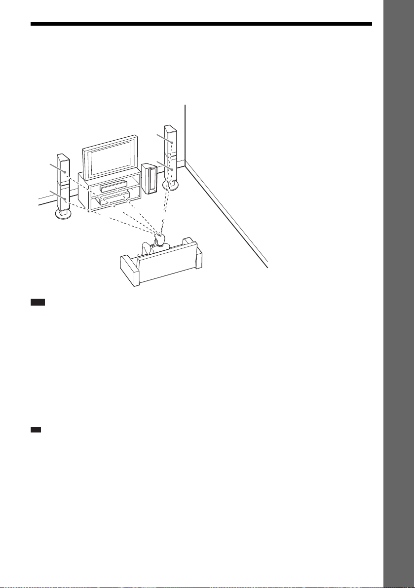
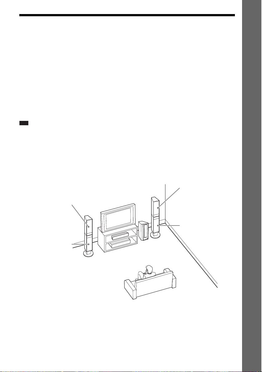
Step 2: Positioning the System
p
For the best possible surround sound, all the speakers other than the subwoofer should be placed at the
same distance from the listening position (A).
Place the system as illustrated below.
A Front speaker (L (left))
B Front speaker (R (right))
C Center speaker
D Surround speaker (L (left))
E Surround speaker (R (right))
F Subwoofer
G Unit
A
B
E
Getting Started
D
Note
• Do not set the speakers in an inclined position.
• Do not place the speakers in locations that are:
– Extremely hot or cold
– Dusty or dirty
– Very humid
– Subject to vibrations
– Subject to direct sunlight
• Use caution when placing the speakers and/or speaker stands attached to the speakers on a specially treated (waxed,
oiled, polished, etc.) floor, as staining or discoloration may result.
• Do not use any type of abrasive pad, scouring powder, or solvent such as alcohol or benzine.
• Do not lean or hang on the speaker, as the speaker may fall down.
Ti
• When you change the positions of the speakers, Sony recommends that you change the settings. For details, see
“Getting Optimal Surround S ound for a Room” (page 78) and “Ca librating the Appropriate Settings Automatically”
(page 79).
• Since the system is equipped with S-Force PRO Front Surround technology (page 105), you can enjoy surround
sound with the speaker positions illustrated above.
To obtain the S-Force PRO Front Surround, do all the following:
– set [ALL FRONT] or [ALL FRONT - NO CENTER] in the [SPEAKER FORMATION] setting (page 78).
– set the decoding mode to “A.F.D. MULTI” (page 31).
– play a multi channel source.
– set the sound mode (page 33) to “AUTO,” “MOVIE,” “MUSIC,” or “NEWS.”
A
A
G
A
F
A
C
GB
15
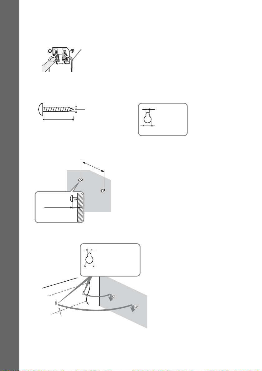
To install the center speaker on a wall
Before installing the center speaker on a wall, connect the speaker cord to the speaker.
Be sure to match the speaker cords to the appropriate terminals on the speaker: the speaker cord with
the color tube to 3, and the speaker cord without the color tube to #.
Color tube
Center speaker: Green
Getting Started
1 Prepare screws (not supplied) that are suitable for the hole on the back of each speaker.
See the illustrations below.
5
4 mm (
/32 inch)
30 mm (1 3/16 inches)
2 Fasten the screws to the wall.
265 mm
1
(10
/2 inches)
8 to 10 mm
11
/32 to 13/32
(
inch
)
3 Hang the speakers on the screws.
5 mm
7
(
/32 inch)
10 mm
13
/32 inch)
(
5 mm
7
/32 inch)
(
10 mm
13
(
/32 inch)
Hole on the back of
the speaker
Hole on the back of
the speaker
16
Rear of speaker
GB

Note
• Use screws that are suitable for the wall material and strength. As a plaster board wall is especially fragile, attach
the screws securely to a beam and fasten them to the wall. Install the center speaker on a vertical and flat wall where
reinforcement is applied.
• Contact a screw shop or installer regarding the wall material or screws to be used.
• Sony is not responsible for accident or damage caused by improper installation, insufficient wall strength or
improper screw installation, natural calamity, etc.
Getting Started
17
GB
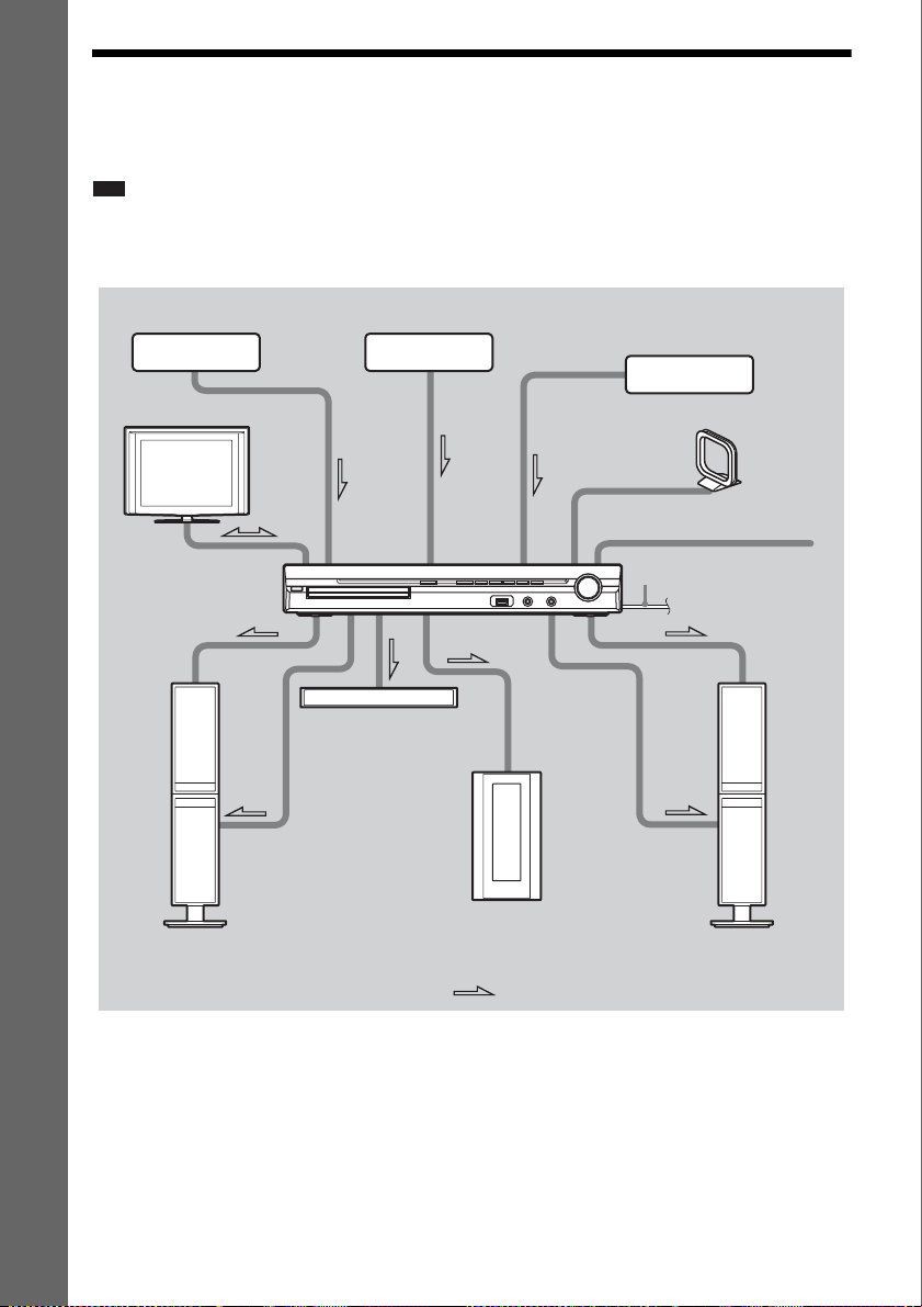
Step 3: Connecting the System
See the connection diagram below, and read the additional information from 1 to 5 on the following
pages.
Note
• Be sure to make connections securely to avoid hum and noise.
• When you connect another component with a volume control, turn up the volume of the other components to a level
Getting Started
where sound is not distorted.
3 DIGITAL MEDIA
PORT adapter
2 TV
1 Front/surround
speakers (L)
3 Portable audio source
1 Center speaker
3 VCR, digital satellite receiver,
or PlayStation, etc.
4 AM loop antenna (aerial)
4 FM wire antenna (aerial)
5 AC power cord (mains lead)
1 Subwoofer
1 Front/surround
speakers (R)
:Signal flow
18
GB
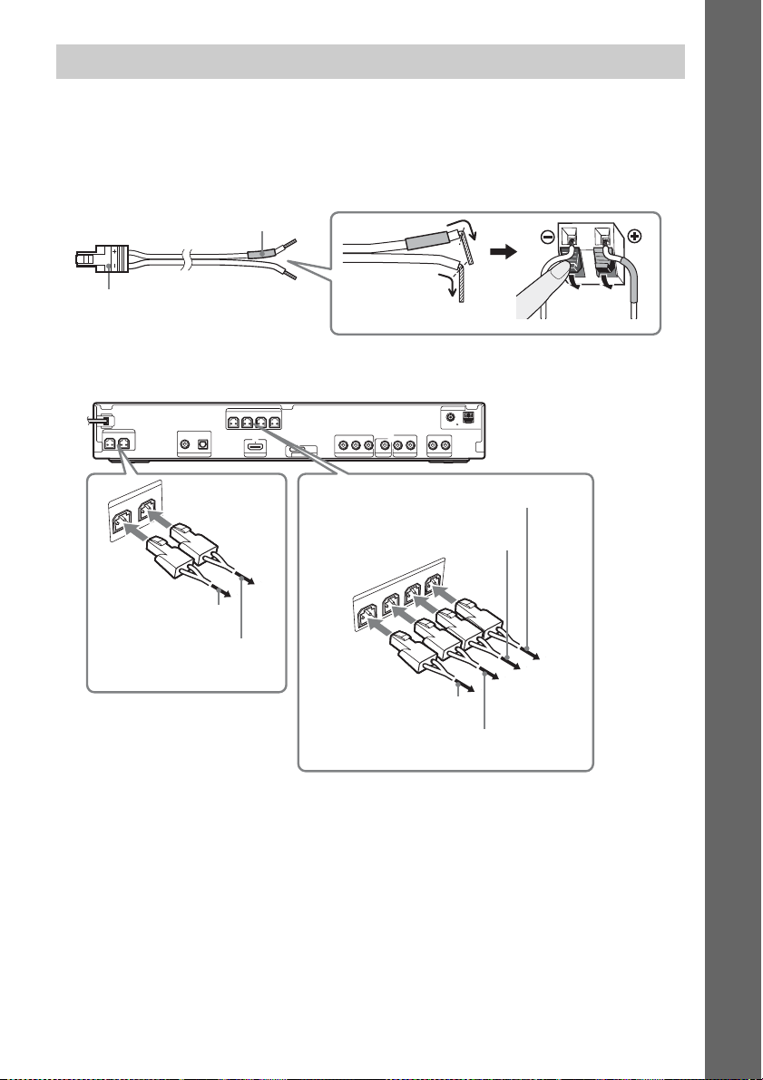
1 Connecting the Speakers
The connector and color tube of the speaker cords are the same color as the label of the jacks to be
connected. Be sure to match the speaker cords to the appropriate terminals on the speakers: the speaker
cord with the color tube to 3, and the speaker cord without the color tube to #. Do not catch the
speaker cord insulation in the speaker terminals.
Rear of speaker
Color tube
(+)
Getting Started
Connector
(–)
When connecting to the unit, insert the connector until it clicks.
Rear panel
SPEAKER
CENTER SUBWOOFER
R
E
F
O
O
W
SPEAKER
B
U
S
R
E
T
N
E
C
To the center speaker
(green)
To the subwoofer
(purple)
DIGITAL IN
COAXIAL OPTICAL
TV HDMI OUT
SPEAKER
FRONT R FRONT L SUR R SUR L
DC5V
0.7A MAX
B/CBPR/CR
Y
P
COMPONENT VIDEO OUT
VIDEO OUT TV
DMPORT
To the surround speaker (L)
(blue)
To the surround speaker (R)
(gray)
O
R
F
R
T
N
O
R
F
To the front speaker (R)
(red)
To the front speaker (L) (white)
LR
AUDIO IN
SAT/CABLE
R
SU
R
R
SPEAKER
U
S
L
T
N
ANTENNA
COAXIAL 75
AM
FM
AUDIO IN LR
L
19
GB
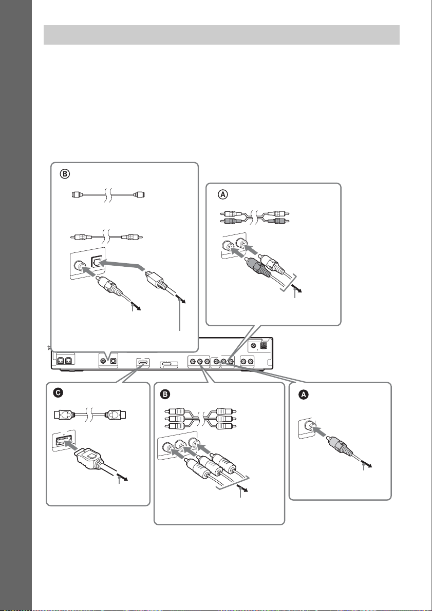
2 Connecting the TV
Use the parts as follows:
•Video cord (1)
To listen to TV sound from the six speakers of the system, connect the TV and the system with the
audio cord (not supplied) (A).
Getting Started
For video output to your TV, check the video input jacks of the TV, and select connection method A,
B, or C. Picture quality improves in order from A (standard) to C (HDMI).
When the TV has the digital optical or coaxial output jack, you can improve sound quality by
connecting with the digital cord (B).
Digital optical cord
(not supplied)
Audio cord
(not supplied)
Digital coaxial cord
(not supplied)
DIGITAL IN
COAXIAL OPTICAL
TV
or
To the digital coaxial output jack of
the TV
To the digital optical output jack of
the TV
SPEAKER
CENTER SUBWOOFER
DIGITAL IN
COAXIAL OPTICAL
TV HDMI OUT
SPEAKER
FRONT R FRONT L SUR R SUR L
L
AUDIO IN
R
TV
To the AUDIO OUT jacks of the TV
ANTENNA
COAXIAL 75
FM
DC5V
0.7A MAX
B/CBPR/CR
Y
P
DMPORT
COMPONENT VIDEO OUT
VIDEO OUT TV
LR
AUDIO IN LR
AUDIO IN
SAT/CABLE
AM
White
Red
Rear panel
HDMI** cable
(not supplied)
T
U
I O
M
D
H
To the HDMI IN jack of the TV
Component video cord
(not supplied)*
Green
Blue
Red
R
/C
R
P
B
/C
B
P
T
U
O
O
Y
E
ID
V
T
N
E
N
O
P
M
O
C
To the COMPONENT VIDEO IN jacks
of the TV
Video cord
(supplied)
T
U
O
O
E
ID
V
To the VIDEO IN jack of
the TV
* If your TV accepts progressive format signals, use this connection and set the output signal of the system to
progressive format (page 28).
** HDMI (High-Definition Multimedia Interface)
If your TV has the HDMI jack, use this connection and select the type of output signal (page 28).
GB
20

Note
• During the “D MPORT” function, video signal is not output from the HDMI OUT and COMPONENT VIDEO OUT
jacks.
• The system can accept both digital and analog signals. Digital signals have priority over analog signals. (COAXIAL
has priority over OPTICAL.) If the digital signal ceases, the analog signal will be processed after 2 seconds.
To change the color system (PAL or NTSC) (Asian, Australian, and
Middle Eastern models only)
Depending on the TV to be connected, you may be required to select either PAL or NTSC for the color
system.
The initial setting of the system for Australian and Middle Eastern models is PAL.
The initial setting of the system for Asian models is NTSC.
1 Turn off the system by pressing "/1.
2 Turn on the system by pressing "/1 while pressing X on the unit.
Each time you perform this operation, the color system toggles between PAL and NTSC.
“NTSC” lights up in the front panel display when the color system is set to NTSC.
Getting Started
21
GB
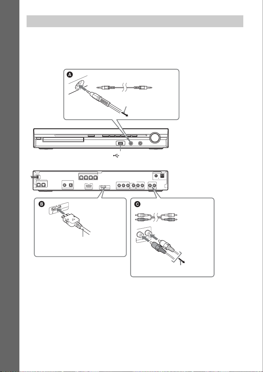
3 Connecting the other components
You can enjoy the connected component using the six speakers of the system.
• Portable audio source: A
• DIGITAL MEDIA PORT adapter: B
• VCR, digital satellite receiver, or PlayStation, etc.: C
Getting Started
Stereo mini-plug cord
(not supplied)
To the portable audio
source
(USB) port (See page 68.)
Front panel
SPEAKER
CENTER SUBWOOFER
O
P
M
D
DIGITAL MEDIA PORT adapter
(not supplied)
DIGITAL IN
COAXIAL OPTICAL
TV HDMI OUT
5V
C
D
X
A
M
A
.7
0
T
R
FRONT R FRONT L SUR R SUR L
SPEAKER
DC5V
0.7A MAX
B/CBPR/CR
Y
P
COMPONENT VIDEO OUT
VIDEO OUT TV
DMPORT
LR
AUDIO IN LR
AUDIO IN
SAT/CABLE
Audio cord
(not supplied)
L
IN
AUDIO
R
BLE
SAT/CA
COAXIAL 75
ANTENNA
FM
AM
Rear panel
White
Red
To the AUDIO OUT jacks of another
component
To connect the DIGITAL MEDIA PORT adapter
Connect a DIGITAL MEDIA PORT adapter (not supplied) to the DMPORT jack. For details, see
“Using the DIGITAL MEDIA PORT Adapter” (page 77).
22
GB
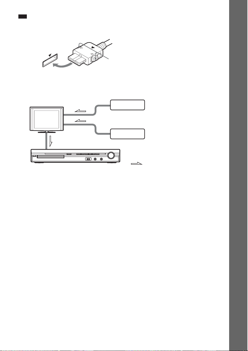
Note
• Connect the DIGITAL MEDIA PORT adapter so that the V marks are aligned. When disconnecting, pull out while
pressing A.
A
If your TV has multiple audio/video inputs
You can enjoy the sound with the speakers of the system through the connected TV. Connect the
components as follows.
TV
System
VCR, digital satellite receiver
or PlayStation, etc.
VCR, digital satellite receiver
or PlayStation, etc.
:Signal flow
Select the component on the TV. For details, refer to the operating instructions of the TV.
If the TV does not have multiple audio/video inputs, a switcher will be necessary to receive the sound
from more than two components.
Getting Started
23
GB
p
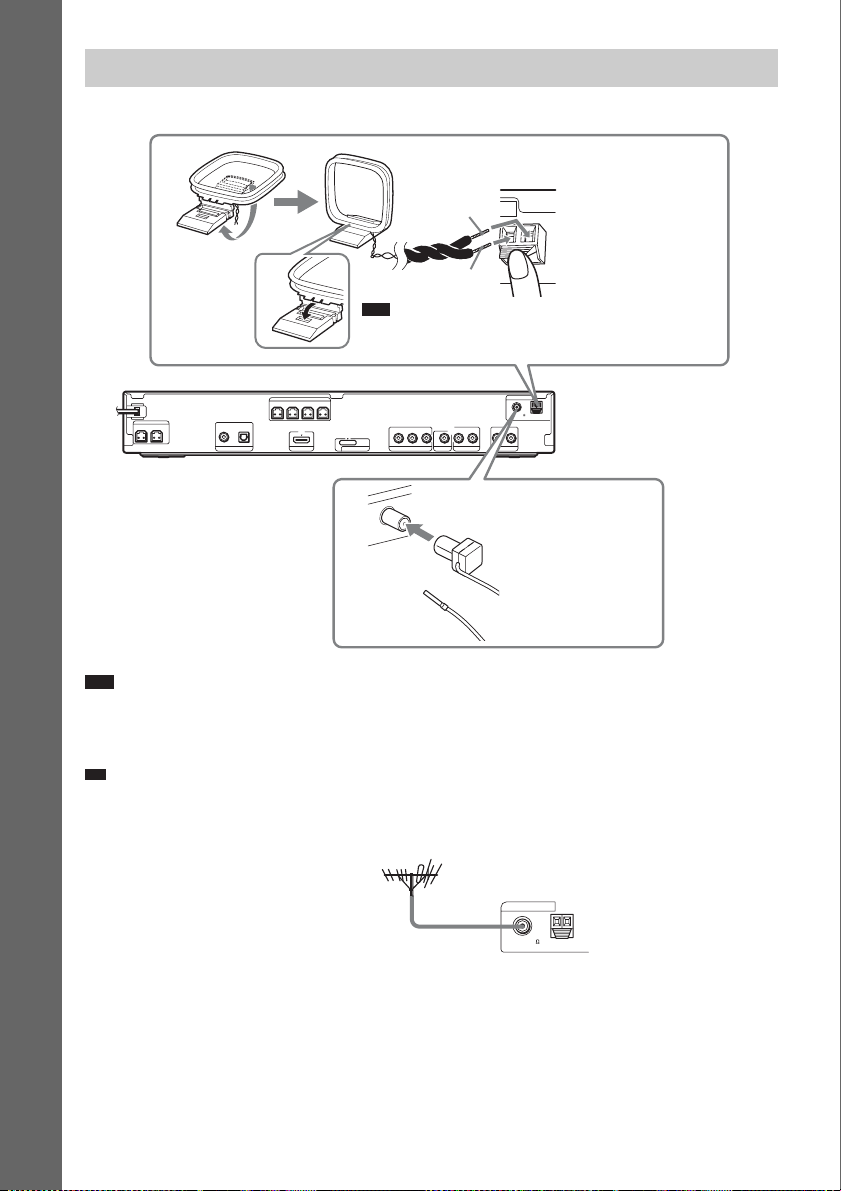
4 Connecting the antenna (aerial)
Getting Started
AM loop antenna (aerial)
(supplied)
A
B
Note
• Cord (A) or cord (B) can be connected to either terminal.
ANTENNA
Rear panel
COAXIAL 75
AM
FM
AUDIO IN LR
LR
AUDIO IN
SAT/CABLE
SPEAKER
CENTER SUBWOOFER
DIGITAL IN
COAXIAL OPTICAL
TV HDMI OUT
SPEAKER
FRONT R FRONT L SUR R SUR L
DC5V
0.7A MAX
B/CBPR/CR
Y
P
A
IA
X
A
VIDEO OUT TV
COMPONENT VIDEO OUT
A
N
N
TE
N
FM wire antenna (aerial)
(supplied)
5
7
L
M
F
DMPORT
O
C
or
Note
• Keep the AM loop antenna (aerial) and cord away from the system or other AV components, as noise may result.
• Be sure to fully extend the FM wire antenna (aerial).
• After connecting the FM wire antenna (aerial), keep it as horizontal as possible.
Ti
• Adjust the direction of the AM loop antenna (aerial) for best AM broadcast sound.
• If you have poor FM reception, use a 75-ohm coaxial cable (not supplied) to connect the unit to an outdoor FM
antenna (aerial) as shown below.
Outdoor FM antenna (aerial)
Unit
ANTENNA
COAXIAL 75
FM
AM
GB
24
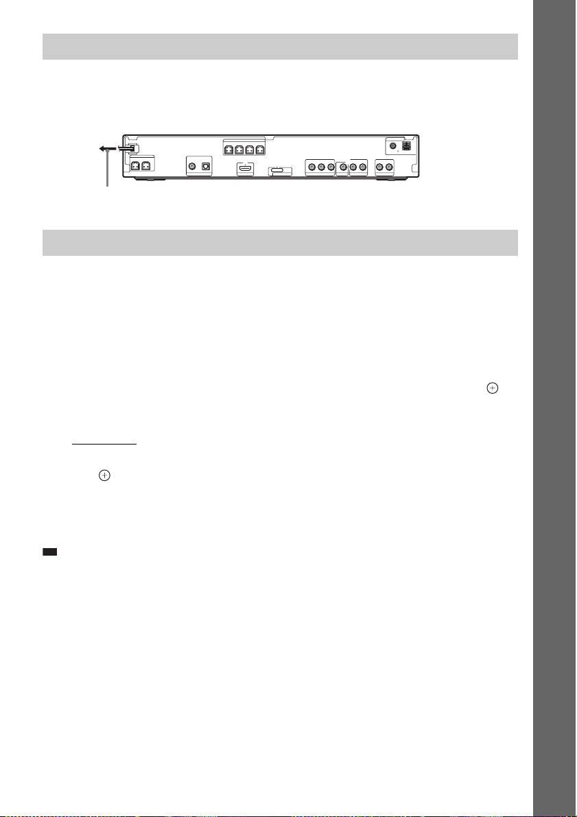
p
5 Connecting the AC power cord (mains lead)
Before connecting the AC power cord (mains lead) of the unit to a wall outlet (mains), connect all the
speakers to the unit.
Getting Started
Rear panel
ANTENNA
COAXIAL 75
AM
FM
LR
AUDIO IN LR
AUDIO IN
SAT/CABLE
SPEAKER
CENTER SUBWOOFER
DIGITAL IN
COAXIAL OPTICAL
TV HDMI OUT
SPEAKER
FRONT R FRONT L SUR R SUR L
DC5V
0.7A MAX
B/CBPR/CR
Y
P
COMPONENT VIDEO OUT
VIDEO OUT TV
DMPORT
To the wall outlet (mains)
About the demonstration
After connecting the AC power cord (mains lead), the demonstration appears in the front panel display.
Setting the demonstration mode to on/off
1 Press [/1 on the unit.
The system turns on.
2 Press SYSTEM MENU.
3 Press X/x repeatedly until “DEMO” appears in the front panel display, then press or
c.
4 Press X/x to select a setting.
•“DEMO ON”: On.
• “DEMO OFF”: Off.
5 Press .
The setting is made.
6 Press SYSTEM MENU.
The system menu turns off.
Ti
• When you purchase the system from new, or if the system is at its factory default settings (ex., after performing
“COLD RESET” (page 90)), you can turn off the demonstration simply by pressing [/1 on the remote.
GB
25

Step 4: Performing the Quick Setup
Follow the Steps below to make the basic
adjustments for using the system.
Displayed items vary depending on the country
model.
Getting Started
Note
• When you connect the system and the TV with the
component video cord (not supplied) or HDMI cable
(not supplied), you need to set the type of video
output for matching your TV. For details , see “Setting
the type of video output to match your TV” (page 28).
"/1
The Setup Display for selecting the
language used in the on-screen display
appears.
LANGUAGE SETUP
OSD:
MENU:
AUDIO:
SUBTITLE:
ENGLISH
ENGLISH
FRENCH
SPANISH
PORTUGUESE
5 Press X/x to select a language.
The system displays the menu and subtitles
in the selected language.
6 Press .
The Setup Display for selecting the aspect
ratio of the TV to be connected appears.
C/X/x/c,
DISPLAY
1 Turn on the TV.
2 Press [/1.
Note
• Make sure that the function is set to “DVD”
(page 29).
3 Switch the input selector on your TV so
that the signal from the system
appears on the TV screen.
[Press [ENTER] to run QUICK SETUP.]
appears at the bottom of the TV screen. If
this message does not appear, recall the
Quick Setup display (page 27) and perform
again.
4 Press without inserting a disc.
VIDEO SETUP
TV TYPE:
PROGRESSIVE
4:3 OUTPUT:
COLOR SYSTEM
PAUSE MODE:
(COMPONENT OUT)
4:3 LETTER BOX
(VIDEO CD)
16:9
16:9
:
4:3 PAN SCAN
:
AUTO
7 Press X/x to select the setting that
matches your TV type.
x If you have a wide-screen TV or a 4:3
standard TV with a wide-screen mode
[16:9] (page 54)
x If you have a 4:3 standard TV
[4:3 LETTER BOX] or [4:3 PAN SCAN]
(page 54)
8 Press .
The Setup Display for selecting the speaker
formation appears.
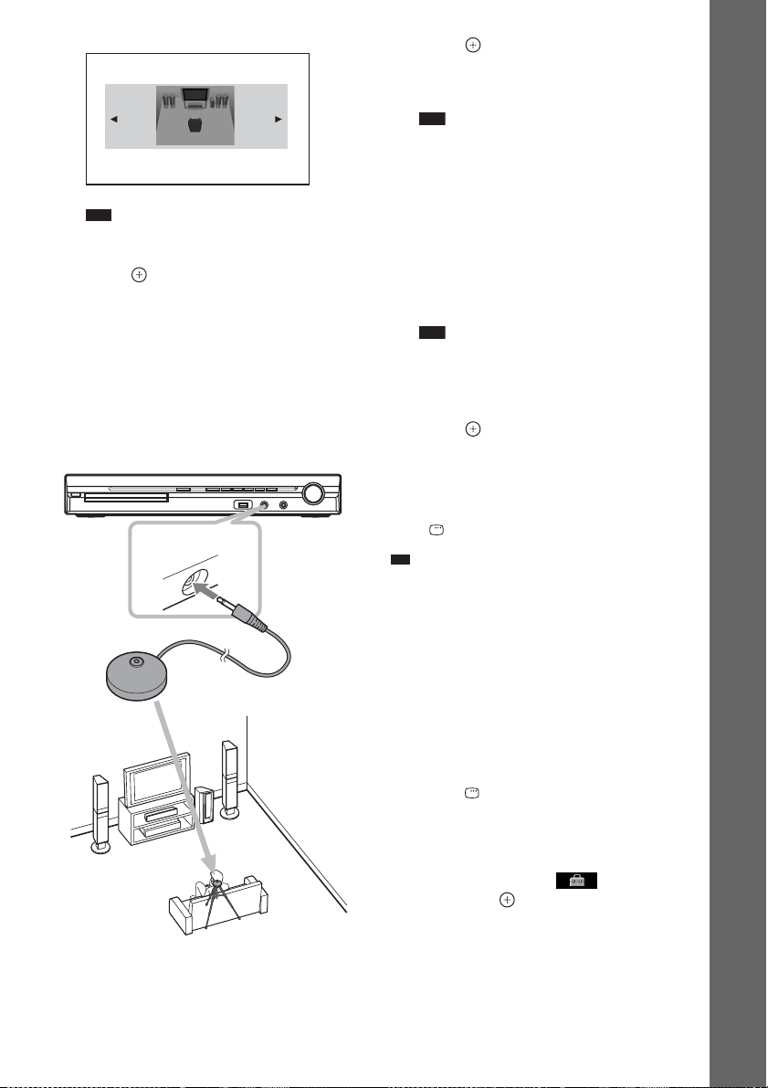
9 Press C/c to select the speaker
formation image as the speakers are
actually positioned.
When you install the speakers by the
standard assembly (page 9), select [ALL
FRONT].
For details, see “Getting Optimal Surround
Sound for a Room” (page 78).
26
GB
p
SPEAKER FORMATION
ALL FRONT
Note
• The image in the illustration above is different
from the actual system.
10 Press .
11 Connect the calibration mic to the
A.CAL MIC jack on the front panel.
Set up the calibration mic at the ear level
using a tripod, etc. (not supplied). The front
of each speaker should face the calibration
mic, and there should be no obstruction
between the speakers and the calibration
mic.
A.CAL MIC
AUDIO IN / MIC1 /
Calibration mic
13Press .
[AUTO CALIBRATION] starts.
Be quiet during the measurement.
Note
• Loud test sound is output when [AUTO
CALIBRATION] starts. You cannot turn the
volume down. Give consideration to children
and neighbors.
• Avoid being in the measurement area and
making noise during the measurement (which
takes about 1 minute), as it may interfere with
measurement.
14Unplug the calibration mic and press C/
c to select [YES].
Note
• The environment of the room in which the
system is installed may affect measurements.
• If measurement fails, follow the message then
retry [AUTO CALIBRATION].
15Press .
Quick Setup is finished. All connections
and setup operations are complete.
To quit the Quick Setup
Press DISPLAY in any Step.
Ti
• If you change the position of the speakers, reset the
speaker settings. See “Getting Optimal Surround
Sound for a Room” (page 78) and “Calibrating the
Appropriate Settings Automatically” (page 79).
• If you want to change any of the settings, see “Using
the Setup Display” (page 53).
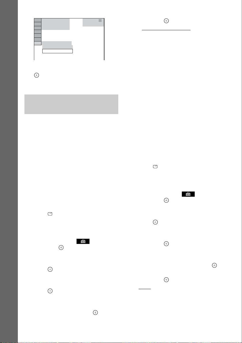
To recall the Quick Setup display
1 Press FUNCTION +/– repeatedly until
“DVD” appears in the front panel
display.
2 Press DISPLAY while the system is
in stop mode.
The Control Menu display appears on the
TV screen.
3 Press X/x to select [SETUP],
then press .
The options for [SETUP] appear.
Getting Started
12 Press C/c to select [YES].
27
GB
94( 99)
Getting Started
1( 1)
T 0: 01: 08
CUSTOM
CUSTOM
QUICK
DVD VIDEO
4 Press X/x to select [QUICK], then press
.
The Quick Setup display appears.
Setting the type of video output to match your TV
Depending on the connection of the TV
(page 20), select the type of video output of the
system.
To select the type of video signal
output from the HDMI OUT jack
When you connect the unit and the TV with the
HDMI cable, select the type of video signals
output from the HDMI OUT jack.
For details, refer also to the operating
instructions supplied with the TV/projector, etc.
1 Press FUNCTION +/– repeatedly until
“DVD” appears in the front panel
display.
2 Press DISPLAY while the system is
in stop mode.
The Control Menu display appears on the
TV screen.
3 Press X/x to select [SETUP],
then press .
The options for [SETUP] appear.
4 Press X/x to select [CUSTOM], then
press .
The Setup Display appears.
5 Press X/x to select [HDMI SETUP], then
press .
The options for [HDMI SETUP] appear.
6 Press X/x to select [HDMI
RESOLUTION], then press .
7 Press X/x to select the desired setting,
then press .
• [AUTO (1920
outputs the optimal video signal for the
connected TV.
• [1920
× 1080i* video signals.
• [1280
720p* video signals.
× 480p]**: The system outputs 720 ×
• [720
480p* video signals.
* i: interlace, p: progressive
** Depending on the country model, [720 × 576p]
may appear.
Does your TV accept progressive
signals?
Progressive is the method for displaying TV
images which reduces flickering and sharpens
the image. To use this method, you need to
connect to a TV that accepts progressive signals.
× 1080p)]: The system
× 1080i]: The system outputs 1920
× 720p]: The system outputs 1280 ×
1 Press FUNCTION +/– repeatedly until
“DVD” appears in the front panel
display.
2 Press DISPLAY while the system is
in stop mode.
The Control Menu display appears on the
TV screen.
3 Press X/x to select [SETUP],
then press .
The options for [SETUP] appear.
4 Press X/x to select [CUSTOM], then
press .
The Setup Display appears.
5 Press X/x to select [VIDEO SETUP],
then press .
The options for [VIDEO SETUP] appear.
6 Press X/x to select [PROGRESSIVE
(COMPONENT OUT)], then press .
7 Press X/x to select the desired setting,
then press .
[OFF]: The system does not output
progressive signals. Select this setting
when:
– your TV does not accept progressive
signals, or,
28
GB
– your TV is connected to jacks other than
the COMPONENT VIDEO OUT jacks.
[ON]: The system outputs progressive
signals. Select this setting when:
– your TV accepts progressive signals,
and,
– the TV is connected to the
COMPONENT VIDEO OUT jacks.
When you select [ON], the confirmation
display appears. Follow the Steps below.
8 Press C/c to select [START], then
press .
The system outputs the progressive signal
for 5 seconds. Check that the screen is
displayed correctly.
9 Press C/c to select [YES], then press
.
The system outputs the progressive signal.
When you select [NO], the system does not
output the progressive signal.
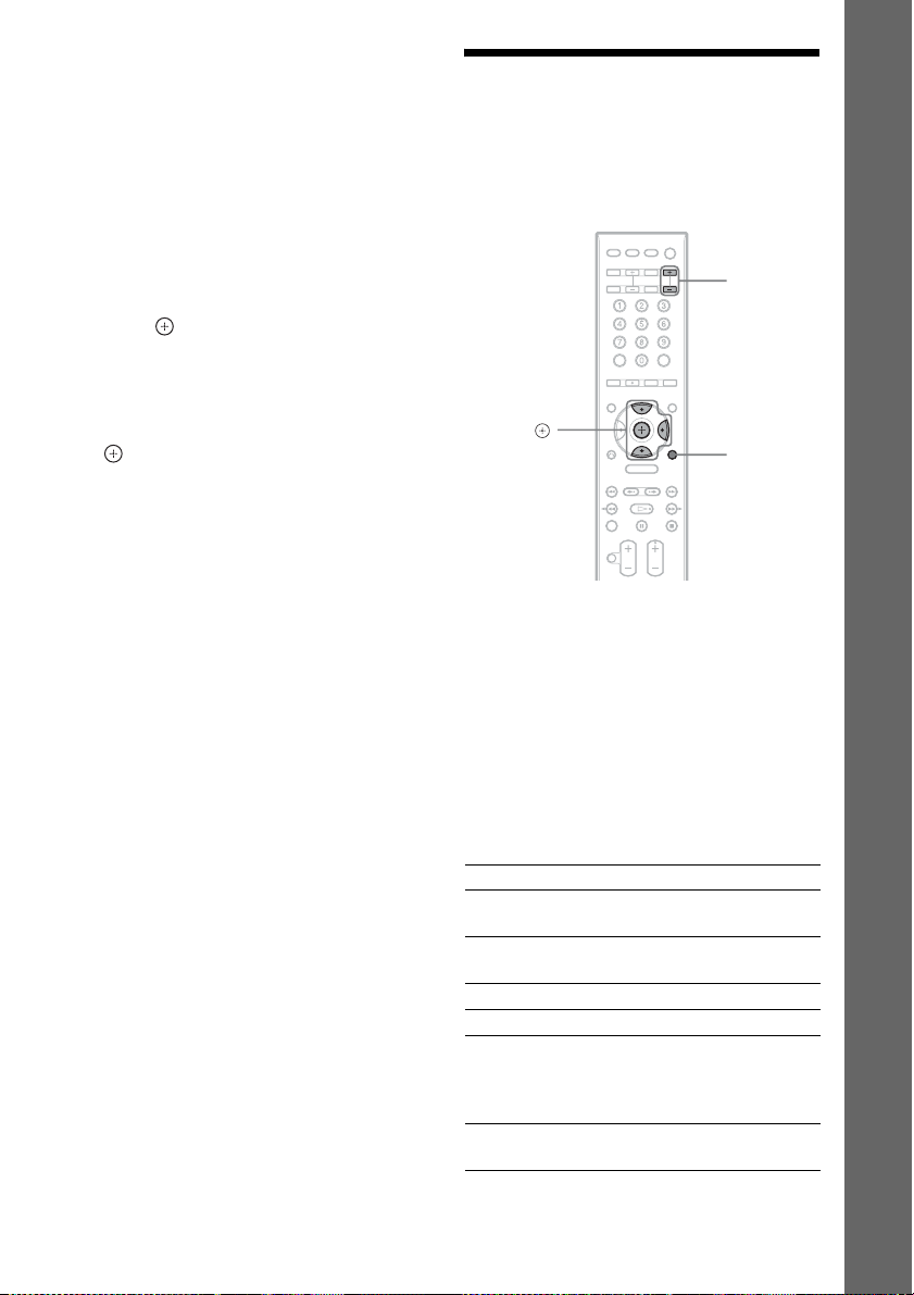
Step 5: Enjoying Sound from all the Speakers
You can enjoy DVD, TV, or VCR sound from
all the speakers in this system.
FUNCTION
+/–
X/x/c,
SYSTEM
MENU
1 Press FUNCTION +/– repeatedly until
the desired function appears in the
front panel display.
Each time you press FUNCTION +/–, the
function changes as follows.
Getting Started
“DVD” t “TUNER FM” t “TUNER
AM” t “USB” t “TV” t “SAT/
CABLE” t “DMPORT” t “AUDIO”
t …
Function Source
“DVD” Disc that is played by the
“TUNER FM”/
“TUNER AM”
“USB” USB device (page 68)
“TV” TV
“SAT/CABLE” Component that is
“DMPORT” DIGITAL MEDIA PORT
system
FM/AM radio (page 62)
connected to the SAT/
CABLE jacks on the rear
panel
adapter (page 77)
29
GB

p
Function Source
“AUDIO” Portable audio source (that
Note
• When you use both the TV (AUDIO IN) jacks
(analog connection) and TV (COAXIAL or
Getting Started
OPTICAL DIGITAL IN) jack (digital
connection) at the same time, the digital
connection takes priority.
is connected to the AUDIO
IN jack on the front panel)
2 Press SYSTEM MENU.
3 Press X/x repeatedly until “DEC.
MODE” appears in the front panel
display, then press or c.
4 Press X/x repeatedly until the
decoding mode you want appears in
the front panel display.
When you want to output the TV sound or
stereo sound of a 2 channel source from the
six speakers, select the “PRO LOGIC,”
“PLII MOVIE,” or “PLII MUSIC”
decoding mode.
For details, see page 31.
5 Press .
The setting is made.
6 Press SYSTEM MENU.
The system menu turns off.
Note
• Depending on your TV, you may ne ed to turn off your
TV’s speaker to enjoy surround sound of the system.
Ti
• When listening to audio files using a portable audio
source, you can enhance the sound.
Press FUNCTION +/– to select “AUDIO.” Connect
the portable audio source. Select “A.F.D. STD” for
“DEC. MODE” and set the sound mode (page 33) to
“MOVIE,” “MUSIC,” or “NEWS.”
To cancel, select other than “A.F.D. STD.”
Changing the input level of the sound from connected components
Distortion may occur when you listen to a
component connected to the TV, SAT/CABLE
jacks on the rear panel, or to the AUDIO IN jack
on the front panel. Distortion is not a
malfunction and will depend on the component
connected.
To prevent distortion, reduce the input level on
the unit.
1 Press FUNCTION +/– repeatedly until
“TV,” “SAT/CABLE,” or “AUDIO”
appears in the front panel display.
2 Press SYSTEM MENU.
3 Press X/x repeatedly until
“ATTENUATE” appears in the front
panel display, then press or c.
4 Press X/x to select a setting.
• “ATT ON”: You can attenuate the input
level. The output level is changed.
• “ATT OFF”: Normal input level.
5 Press .
The setting is made.
6 Press SYSTEM MENU.
The system menu turns off.
GB
30
 Loading...