

Page 1
2-108-866-11(1)
DVD Home Theatre
System
Operating Instructions
Mode d’emploi
US
FR
DAV -FR10W
©2004 Sony Corporation
Page 2

3
WARNING
To prevent fire or shock hazard, do not
expose the unit to rain or mo ist u r e.
Caution – The use of optical instruments with this
product will increase ey e haz ard .
For the customers in the U.S.A
This symbol is i ntend ed to alert the user to
the presence of uninsulated “dangerous
voltage” within the product’s enclosure
that may be of suffici ent magnitude to
constitute a risk of electric shoc k to
persons.
This symbol is i ntend ed to alert the user to
the presence of important operating and
maintenance (servicing) instructions in the
literature accompany ing the appliance.
Owner’s Record
The model and seria l numbers are lo cated at the botto m
of the unit. Record the serial number in the space
provided below. Refer to them whenever you call upon
your Sony dealer regarding this product.
Model No. DAV-FR10W
Serial No.______________
WARNING
This equipment has been tested and found to comply
with the limits for a Class B digital device, pursuant to
Part 15 of the FCC Rules. These limits are designed to
provide reasonable protectio n against harmful
interference in a residential installation. This
equipment generates, uses, and ca n r adia te radio
frequency energy and, if not in sta ll ed and used in
accordance with the instructi ons , may cau s e harmful
interference to radio communications. However, there
is no guarantee that interference will not occur in a
particular installa tion. If this equipment does cause
harmful interference to r a dio or te le vision reception,
which can be determined by turning the equipment off
and on, the user is encouraged to try to correc t the
interference by one or more of the following measures:
– Reorient or relocate the rece iv i ng an tenna.
– Increase the separation betwe e n the equi pment and
system.
– Connect the equipment into an outlet on a circuit
different from that to which the system is connected.
– Consult the dealer or an experie nc e d radio/TV
technician for help.
CAUTION
You are cautioned that any changes or modif icat ions
not expressly approved in this manual could void your
authority to operate this equipm ent .
Note to CATV system installer:
This reminder is provided to call the CATV system
installer’s attention to Article 820-40 of the NEC th a t
provides guidelines for proper ground ing a nd, in
particular, specifies that the cable ground shall be
connected to the grounding system of the building, as
close to the point of cable entry as practical.
For the customers in Canada
CAUTION
TO PREVENT ELECTRIC SHOCK, MATCH WIDE
BLADE OF PLUG TO WIDE SLOT, FULLY
INSERT.
US
2
Page 3

Precautions
Safety
• If anything falls into the cabinet, unplug the unit and
have it checked by qualified personnel be f or e
operating it any further.
• The uni t is not disc onne c ted f ro m the AC power
source (mains) as l ong a s it is con nect ed t o the ma ins
outlet, even if the unit itse lf ha s be en turned off.
• Unp lug the unit from the wall outlet if you do not
intend to use it for an extended per iod of time. To
disconnect the cord, pull it out by the plug, nev er by
the cord.
Installing
• Allow adequate air ci r culation to prevent i nternal
heat buildup.
• Do not place the unit on surfaces (r ugs, blankets, etc.)
or near materials (curtains, draperies) that may block
the ventilation slots.
• Do not install the unit near heat sources such as
radiators, or air ducts, or in a place subject to direct
sunlight, excessive dust, mechanical vibration, or
shock.
• Do not install the unit in an inclined position. It is
designed to be operated in a horizontal position only.
• Keep the unit and discs away from equipment with
strong magnets, such as microwave ove ns, or large
loudspeakers.
• Do not pla ce he av y obje c ts on the unit.
• If the unit is brought directly from a cold to a warm
location, moisture may conde nse insi de the DVD
Home Theatre System and cause damage to the
lenses. When you first install the unit, or when you
move it from a cold to a warm location, wait for about
30 minutes before operating th e unit.
®
ENERGY STAR
registered mark.
As an ENERGY STAR
Sony Corporation has determine d
that this product meets the
ENERGY STAR
energy efficiency.
is a U.S.
®
partner ,
®
guidelines for
Welcome!
Thank you for purchasing Sony DVD Home
Theatre System. Before operating this system,
please read this manual thoroughly and retain it
for future re ference.
Precautions
On power sources
AC power cord must be changed only at the qual if ie d
service shop.
On placement
• Place the system in a location with ade q uate
ventilation to prevent heat build-up in the system.
• At high volume, over long periods of time, the cabinet
becomes hot to the touch. This is not a malfunction.
However, touching the cabinet should be avoided. Do
not place the unit in a confined space where
ventilation is poor as this may cause overheating.
• Do not block the cooling fan or ventilation slots by
putting anything on the system. Also, do not place the
system on a soft surface such as a rug tha t might block
the ventilation holes on the bott om. The system is
equipped with a high power amplifier. If the cooling
fan or ventilation slots are blocked, the unit can
overheat and malfunction.
• D o not place the system in a location near heat
sources, or in a place subject to direct sunlight,
excessive dust, or mechanical shoc k.
On operation
• If the system is brought directly from a cold to a warm
location, or is placed in a very damp room, moisture
may condense on the l enses inside th e system. Shoul d
this occur, the system may not operate properly. In
this case, remove the disc an d leave the system turned
on for about half an hour until the moisture
evaporates.
• When you move the system, take out any disc. If you
don’t, the disc may be damaged.
• For power saving purposes, set the system to standby
mode by pressing the "/1 button (the STANDBY
indicator lights up). To turn off the system
completely, remove the AC power cord (mains lead)
from the wall outlet (mains).
On adjusting volume
Do not turn up the volume while listening to a section
with very low level inputs or no audio signa ls. If you
do, the speakers may be damaged when a peak level
section is suddenly played.
US
3
Page 4

On cleaning
Clean the cabinet, p anel, and co ntrol s with a s oft cloth
slightly moistened with a mild detergent solution. Do
not use any type of abrasive pad, scouring powder or
solvent such as alcohol or benzine .
If you have any questions or problems concerning your
system, please consult your nearest Sony dealer.
On cleaning discs
Do not use a commercially available CD/DVD
cleaning disc. It may cause a malfunction.
On your TV’s color
If the speakers should cause the TV screen to have
color irregularit y, tu rn o ff the T V at on ce the n tur n it
on after 15 to 30 minutes. If color irregularity should
persist, place the speakers farther away from the set.
The nameplate is located on the bottom exterior of the
unit.
IMPORTANT NOTICE
Caution: This system is capable of holding a still
video image or on-screen displa y image on your
television screen indefinitely. If you leave the still
video image or on-screen displa y image displayed
on your TV for an extended period of time you risk
permanent damage to your television screen.
Projection televisions are especially susceptible to
this.
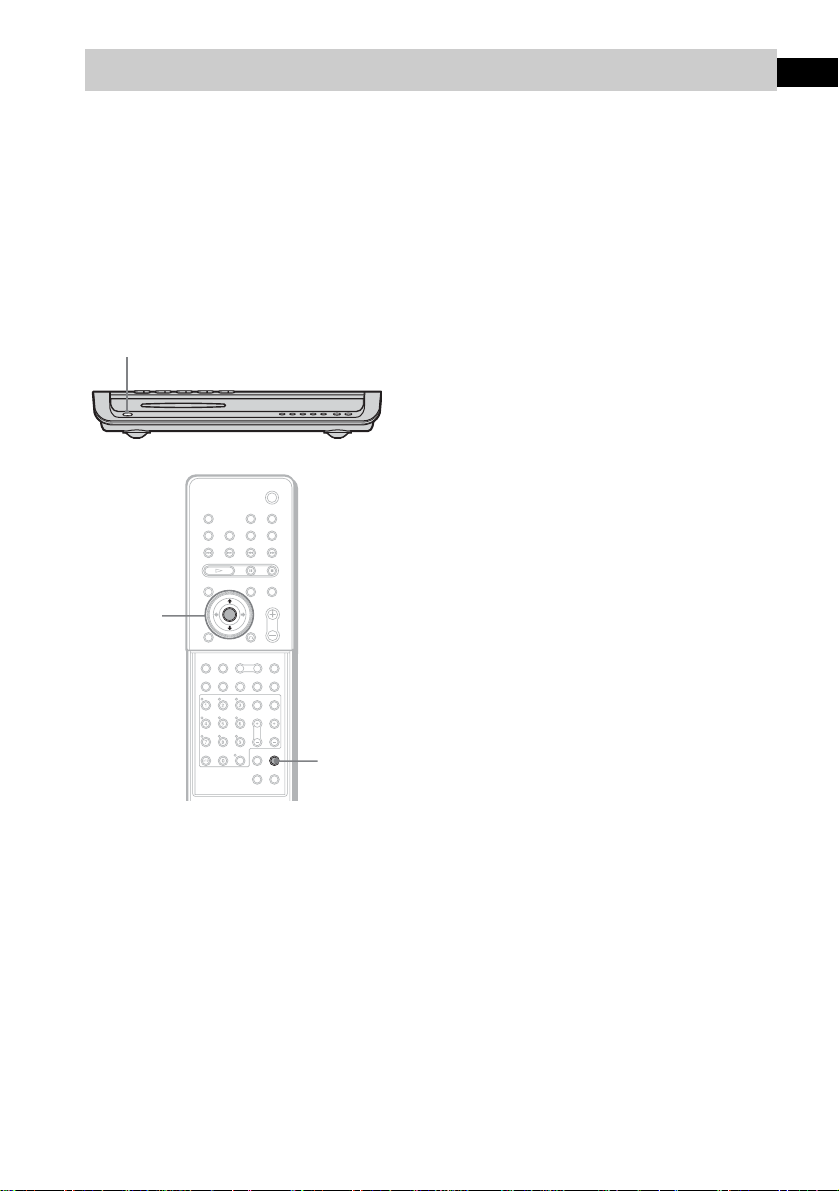
On moving the system
When you carry the system, use the following
procedure to protect the inner mechanism.
1 Make sure that a disc is removed from the
system.
2 Press FUNCTION repeatedly to select
“DVD.”
3 Press ., >, and DISC1 Z
simultaneously.
The front panel display is changed to
“MECHA LOCK.”
To cancel, pre ss "/1.
4 Remove the AC power cord (mains lead)
from the wall outlet (mains).
US
4
Page 5

Table of Contents
Welcome!................................................3
Precautions..............................................3
About This Manual.................................7
This System Can Play the Following
Discs .................................................7
Terms for Discs.......................................7
Notes about Discs...................................9
Note on DVD 5-DISC changer.............10
Guide to the Control Menu Display......11
Getting Started
Unpacking.............................................13
Inserting Batteries into the Remote.......13
Step 1: Speaker System Hookup...........14
Step 2: Antenna (aerial) Hookups.........21
Step 3: TV and Video Component
Hookups..........................................23
Step 4: Connecting the AC Power Cord
(Mains Lead)...................................27
Step 5: Adjusting the Wireless
System ............................................28
Step 6: Performing the Quick Setup .....33
Speaker Setup........................................35
Playing Discs
Playing Discs ........................................36
Resuming Playback from the Point Where
You Stopped the Disc.....................38
(Resume Play)
Using the DVD’s Menu........................39
Playing VIDEO CDs with PBC Functions
(Ver. 2.0).........................................39
(PBC Playback)
Playing an MP3 Audio Track ...............40
Playing JPEG Image Files ....................42
Selecting the Play Mode .......................44
(All Discs, One Disc, or Album)
Creating Your Own Program................45
(Program Play)
Playing in Random Order .....................47
(Shuffle Play)
Playing Repeatedly...............................48
(Repeat Play)
Searching for a Particular Point on
a Disc..............................................49
(Scan, Slow-motion Play)
Searching for a Title/Chapter/Track/
Index/Album/File...........................50
Viewing Disc Information.................... 52
Sound Adjustments
Changing the Sound..............................57
Enjoying Surround Sound ....................59
Selecting the Surround Back Decoding
Mode............................................... 63
Using the Sound Effect.........................65
Using Various Additional
Functions
Changing the Angles............................66
Displaying Subtitles..............................67
Locking Discs .......................................68
(CUSTOM PARENTAL
CONTROL, PARENTAL
CONTROL)
Other Operat io n s
Controlling TV with the Supplied
Remote ...........................................73
Using the SONY TV DIRECT
Function..........................................75
Using the Video or Other Units............ 76
Enjoying Multiplex Broadcast Sound
(DUAL MONO).............................77
Enjoying the Radio...............................78
Using the Sleep Timer..........................81
Changing the Brightness of the Front
Panel Display.................................. 81
Returning to the Default Settings......... 82
continued
US
5
Page 6

Settings and Adjustments
Using the Setup Display....... .... .... .........83
Setting the Display or Sound Track
Language ........................................84
(LANGUAGE SETUP)
Settings for the Display.........................84
(SCREEN SETUP)
Custom Settings....................................86
(CUSTOM SETUP)
Settings for the Speakers.......................87
(SPEAKER SETUP)
Quick Setup and Resetting
the System.......................................93
(SETUP)
Additional Information
Troubleshooting....................................94
Specifications........................................97
Glossary................................................99
Index to Parts and Controls.................103
Language Code List............................108
DVD Setup Menu List........................109
AMP Menu List..................................111
Index ...................................................112
Quick Reference for Remote
Commander ..................................114
US
6
Page 7
About This Manual
• The instructions in this manual describe the
controls on the remote. You can also use the
controls on the system if they have the same or
similar names as those on the remote.
• The following symbols are used in this
manual.
Format of
discs
CD-R/CD-RW
(audio data)
(MP3 files)
(JPEG files)
Disc logo
Symbol Meaning
Functions available for DVD
VIDEOs, DVD-Rs/DVD-RWs in
video mode, and DVD+Rs/
DVD+RWs
Functions avai la ble in VIDEO CD
mode
Functions avai la ble in CD mode
Functions available in Super Audio
CD and Audio CD mode
Functions available for MP3* audio
tracks
Functions avai la ble for JPEG files
* MP3 (MPEG1 Audio Layer 3) is a standard format
defined by ISO/MPE G which compresses audi o data.
This System Can Play the
Following Discs
Format of
discs
DVD VIDEO
Super Audio
CD
VIDEO CD
Audio CD
Disc logo
The “DVD VIDEO” logo is a trademark.
Terms for Discs
• Title
The longest section of a picture or music
feature on a DVD, movie, etc., in video
software, or the entire album in audio
software.
• Chapter
Section of a picture or a music piece that is
smaller than titles. A title is composed of
several chapters . Depending on the disc, no
chapters may be record ed.
• Album
Section of a music piece or an image on a data
CD containing MP3 au di o t ra cks or JPEG
files.
• Track
Section of a picture or a m usic piece on a
VIDEO CD, Super Audio CD, CD, or MP3.
• Index (Super Audio CD, CD) / Video
Index (VIDEO CD)
A number that divides a track into sections to
easily locate the point you want on a VIDEO
CD, Super Audio CD, or CD. Depe nding on
the disc, no indexe s m ay be recorded.
• Scene
On a VIDEO CD with PBC functions
(page 39), the menu screens, mov ing pictures
and still pictures ar e di vided into sections
called “sce nes.”
• File
Section of a picture on a da ta C D containing
JPEG image files.
continued
US
7
Page 8
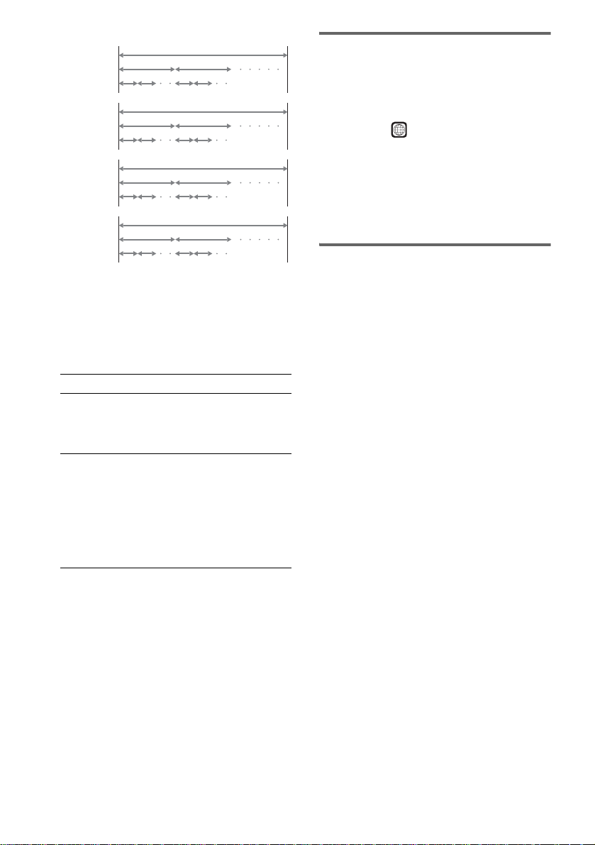
Disc
DVD
structure
VIDEO
CD, Super
Audio CD,
or CD
structure
MP3
structure
JPEG
structure
Title
Chapter
Track
Index
Album
Track
Album
File
Disc
Disc
Disc
Note on PBC (Playback Control)
(VIDEO CDs)
This system conforms to Ver. 1.1 and Ver. 2.0 of
VIDEO CD standards. You can en joy two ki nds
of playback depending on the disc type.
Disc type You can
VIDEO CDs
without PBC
functions
(Ver. 1.1 discs)
VIDEO CDs
with PBC
functions
(Ver. 2.0 discs)
Enjoy video playback (moving
pictures) as well as music.
Play interactive software using
menu screens displayed on the
TV screen (PBC Playback), in
addition to the video playback
functions of Ver. 1.1 discs.
Moreover, you can play highresolution still pictures, if they
are included on the disc.
About Multi Session CD
• This system can play Multi Session CDs when
an MP3 audio track is contained in the first
session. Any subs equent MP3 audio tracks
recorded in later sessions can also be played
back.
• This system can play Multi Session CDs when
a JPEG image file is contained in the f irst
session. Any subs equent JPEG image files
recorded in later sessions can also be played
back.
• If audio tracks and ima ges in music CD fo rmat
or video CD format are recorded in the firs t
session, only the first session will be pla ye d
back.
Region code
Your system has a region code printed on the
back of the unit and will only play DVDs labeled
with the same region code.
DVDs labeled will also play on this system.
ALL
If you try to play any other DVD, the message
[Playback prohibited by area limitations.] will
appear on the TV scree n. D epending on the
DVD, no region code indication may be given
even though playing the DVD is prohibited by
area restrictions.
Examples of discs that the
system cannot play
The system cannot play the following discs:
• CD-ROMs (except for extension “.M P3,”
“.JPG,” or “.JPEG” )
• CD-Rs/CD-RWs other than those recorded in
the following formats:
– audio CD format
– video CD form at
– MP3/JPEG format that conforms to
ISO9660* Level 1/Level 2, or its extended
format, Joliet
• Data part of CD-Extras
• DVD-ROMs
• DVD Audio discs
• DVD-RAMs
• DVD-RWs in VR (Video Recording) mode
• Progressive JPE G fil e
* A logical format of files and folders on CD-ROMs,
defined by ISO (International Organization for
standardization)
Do not load the following discs:
• A DVD with a different region code (page 8,
101).
• A disc that is neithe r s tandard nor circular
(e.g., card, heart, or star shape).
• A disc with paper or stickers on it.
• A disc that has adhesiv e or cellop hane tape s till
left on it.
US
8
Page 9
Notes about CD-R/CD-RW/DVD-R/DVD-RW (Video
mode)/DVD+R/DVD+RW
In some cases, CD-R/CD-RW/DVD-R/DVD-RW
(Video mode)/DVD+R/DVD+RW cannot be played
on this player due to the recording quali ty or physi c al
condition of the disc, or the characteristics of the
recording device and authoring software .
The disc will not play if it has not been correctly
finalized. For more informat ion, se e the ope r ating
instructions for the recor d ing device.
Note that discs created in the Packet Write format
cannot be played.
Music discs encoded with copyright protection
technologies
This product is designed to play back discs that
conform to the Compact Disc (CD) standard.
Recently, various music discs encoded with copyright
protection technol o gies ar e mark eted by some record
companies. Please be aware that am ong those discs,
there are some that do not conform to the CD standard
and may not be playable by this product.
* Manuf actured under license from Dolby
Laboratories.
“Dolby”, “Pro Logic”, and the double-D symbol are
trademarks of Dolby Laboratories.
**Manufactured under license from Digital Theater
Systems, Inc.
“DTS”, “DTS-ES”, “Neo:6”, and “DTS Digital
Surround” are trademarks of Digital T heat er
Systems, Inc.
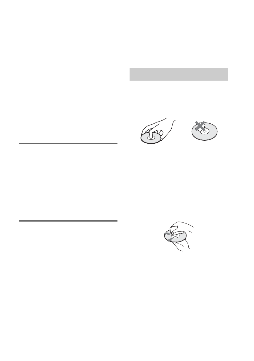
Notes about Discs
On handling discs
• To keep the disc clean, handle the disc by its
edge. Do not touch the surface.
• Do not stick pap er or tape on the disc.
Note on playback operations
of DVDs and VIDEO CDs
Some playback operations of DVDs and VIDEO
CDs may be intentionally set by software
producers. Since this system plays DVDs and
VIDEO CDs according to the disc contents the
software producers designed, some playback
features may not be available. Also, refer to the
instructions supplied with the DVDs or VIDEO
CDs.
Copyrights
This product i ncorporates copyright prot ection
technology that is protected by U.S. patents and
other intellectual property rights. Use of this
copyright protection technology must be
authorized by Macrovision, and is intended for
home and other limited viewing uses only un less
otherwise author ized by Macrovision. Rever se
engineer i ng or disassembly is prohibit ed.
This system incorporates with Dolby* Digital
and Dolby Pro Logic (II) adaptive matrix
surround decoder and the DTS** Digital
Surround System .
• Do not expose the disc to direct sunlight or
heat sources such as hot air du cts, or l eave it in
a car parked in dir ect sunlight as the
temperature may rise considerably inside the
car.
• After playing, store the disc in its case.
On cleaning
• Before playi ng, cl ean the disc with a cleaning
cloth.
Wipe the disc from the center out.
• Do not use solvents such as benzine, thinner,
commercially available cleaners, or anti-static
spray intended for vi nyl LPs.
This system can only play back a standard
circular disc. Using neither standard nor circular
discs (e.g., card, heart, or star shape) may cause
a malfunctio n.
Do not use a disc that has a commercially
available acces s o r y at tached, such as a label or
ring.
US
9
Page 10
Note on DVD 5-DISC
changer
Disc changer system
Stocker
DISC 1
Disc
DISC 3 DISC 4
Playing unit
The disc changer consists of a playing unit and a
stocker which transports the discs to the disc slot
and the playing unit.
For example, if you press DISC 3, the stocker
moves until the DISC 3 comes to the positio n of
the playing unit and then moves the DI SC 3 over
the playing unit.
Notes
• Do not insert or eject discs while playing.
• Noise may come from the disc changer when
changing discs or turning the syste m on and off.
However, this is just noise produced by the operation
of the intern al mechanisms and do es not indicate a
malfunction.
• 8 cm (3-inch) CDs or DVDs cannot be stored in the
stocker.
Do not insert an 8 cm (3-inch) CD with an 8 cm (3inch) adapter. It ma y da mage the system and disc.
DISC 2
DISC 5
10
US
Page 11

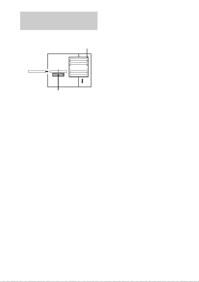
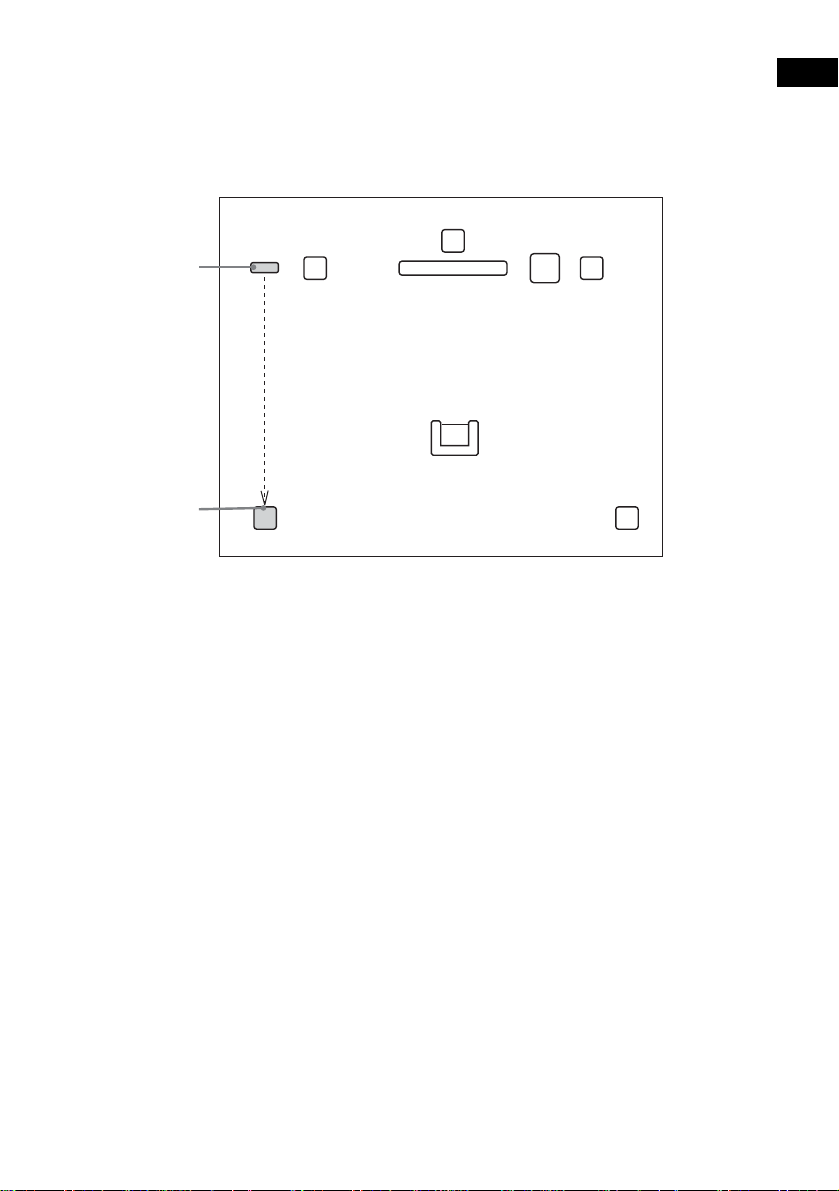
Guide to the Control Menu Display
Use the Control Menu to select a function that you would like to use. The Control Menu display appears
when the DVD DISPLAY button is pressed. For details, refer to the page in parentheses.
Total number of
Currently playing title number (VIDEO
CD/Super Audio CD/CD: track number)
Disc number and
Currently playing chapter
number (VIDEO CD/Super
Audio CD/CD: index number)
Playing time
Icon of selected
Control Menu item
Control Menu items
name or disc type
titles or tracks
recorded
Currently playing
title name
1:DVD
1 2 ( 2 7 ) TITLE 12
)
1 8 ( 3 4
T
1 : 3 2 : 5 5
1: ENGLISH
2: FRENCH
3: SPANISH
Total number of chapters or indexes recorded
Playback status
(NPlayback, XPause, xStop, etc.)
DVD
Type of disc being
played back
Current setting
Options
Function name of selected
Control Menu item
Operation message
SUBTITLE
Select:
List of Control Menu Items
DISC Displays the di sc name or the disc type inser ted into the system.
TITLE (DVD only) (page 50)/
SCENE (only VIDEO CD in PBC playback) /
TRACK (VIDEO CD only) (page 50)
CHAPTER (DVD only) (page 51)/
INDEX (VIDEO CD only) (page 51)
ALBUM (MP3 only) (page 41, 50) Selects the album (MP3) to be pla ye d.
TRACK (Super Audio CD/CD/
MP3 only) (page 41, 50)
INDEX (Super Audio CD/CD only)
(page 51)
TIME (page 52) Checks the elapsed time and the remaining playback time.
AUDIO (DVD/VIDEO CD/Super
Audio CD/CD/MP3 only) (page57)
SUBTITLE (DVD only) (page 67) Displays the subtitles.
ENTER
Selects the title (DVD), or the track (VIDEO CD) to be
played.
Displays the scene (VIDEO CD in PBC play b ack).
Selects the chapter (DVD) or the index (VIDEO CD) to be
played.
Selects the track (Super Audio CD/CD/MP3) to be played.
Displays the index and selects the index (Super Audio CD) to
be played.
Inputs the time code for picture and music searching.
Changes the audio setting .
Changes the subtitle langua ge .
ALBUM (JPEG only) (page 42) Selects the album (JPEG) to be played.
continued
11
US
Page 12
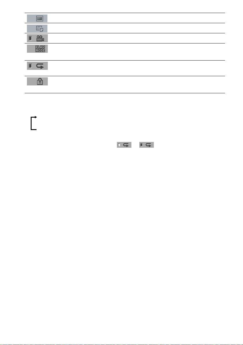
FILE (JPEG only) (page 42) Selects the file (JPEG) to be played.
DATE (JPEG only) (page 56) Displays the date information.
ANGLE (DVD onl y) (p a ge 66) Changes the angle.
PLAYMODE (VIDEO CD/Super
Audio CD/CD/MP3/JPEG only) ( page 44, 47)
REPEAT (page 48) Plays the entire disc (all titles/all tracks), one title/chapter/
CUSTOM PARENTAL
CONTROL (page 68)
Tips
• Each ti me you pre ss DVD DISPL AY, the Control Menu display changes as follows:
Control Menu display
Selects the play mode.
track/album, or contents of program repeatedly.
Sets the disc to prohibit playing.
m
Control Menu display off
The Control Menu items vary, depending on the disc.
• The Control Menu icon indicator lights up in green t unless you se t th e [ REPEAT] setti ng to
[OFF].
• The [ANGLE] indicator lights up in green only when multiple angles are recorded on the disc.
12
US
Page 13

Getting Started
Unpacking
Check that you have the following items:
•Speakers (5)
• Subwoofer (1)
• IR transmitter
• IR receiver
• IR receiver stand
• AM loop antenna (aerial) (1)
• FM wire antenna (a erial) (1)
• Speaker cords (3.5m × 3, 10m × 1) (12ft. × 3,
34ft. × 1)
•Video cord (1)
• Remote Com m ander (remote) RM-SP350 (1)
• Size AAA (R03) batteries (2)
• Operating Instructions
• Speakers - Connection and Installation (card)
(1)
a)
The cords of the IR transmitter and IR receiv er are
for this system only. You cannot use a
commercial ly available exten s ion cord.
b)
Used when the IR receiv er of the surround s peaker
(L) cannot receive infrared ray beca use of the
position. For details, see “Using the IR rec eiv e r ”
(page 30).
a) b)
a)
(1)
(1)
b)
(1)
Inserting Batteries into
Getting Started
the Remote
You can control the system using the supplied
remote. Insert two size AAA (R03) batteries b y
matching the 3 and # ends on the batteries to
the markings inside the compartment. When
using the remote, point it at the remote s ensor
on the system.
Remove the cover.
Notes
• Do not leave the remote in an extremely hot or humid
place.
• D o not use a new battery with an old one.
• Do not drop any foreign object into the remote casing,
particularly when replac ing th e ba tteries.
• Do not expose the remote sensor to direct light from
the sun or lighting apparatus. Doi ng so ma y c au se a
malfunction.
• If you do not use the remote for an extended period of
time, remove the batteries to avoid possible damage
from battery leakage and corros ion.
13
US
Page 14
Step 1: Speaker System Hookup
Connect the supplied speaker system usi n g the supplied speaker cor ds by matching the colors of the
jacks to those of the cords. Do not connect any speakers other than those supplied with this system.
To obtain the best possible surround sound, specify the speak er par ameters (distance, level, etc.) on
page 35.
Required cords
Speaker cords
The connector and the color tube of the speaker cords are the same color as the label of the jacks to be
connected.
(–)
(+)
color tube
(–)
(+)
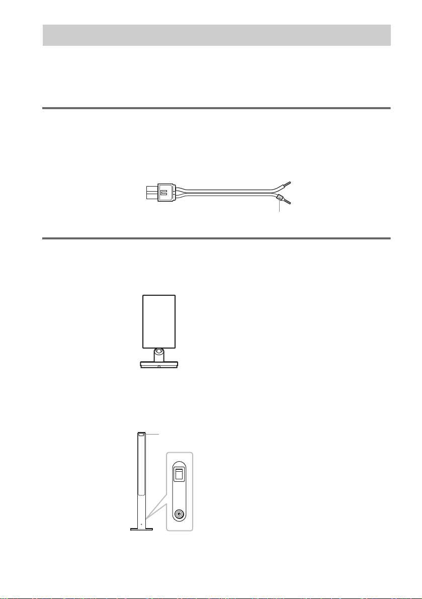
Required equipments for the wireless system
IR transmitter
Transmits the sound by the infrared ray. Connect it to the system.
Surround speaker (L)
The surround speaker (L) incorpora tes the IR receiver. It re ceives the sound from the IR tra nsmitter and
sends it to the surround speaker (R).
Connect the sur round speaker (R).
IR receiver
POWER
ON
14
OFF
ONLY FOR
DIR-R2
Rear side of the surround speaker (L)
US
Page 15
IR receiver
Used when the IR receiver of the surround speaker cannot receive infrared ray because of the position.
Connect to the sur round speaker (L). For de ta i ls , see “Using the IR receiv er ” (page 30).
When using the IR receiver stand, attach the stand so that both delta marks on the IR receiver and stand
are aligned.
IR receiver
Delta marks
IR receiver stand
Note
When you connect the IR receiver to the surround speaker (L), the IR receiver is activated and the IR receiver of the
surround speaker (L) is not activated automatically.
Getting Started
15
US
Page 16
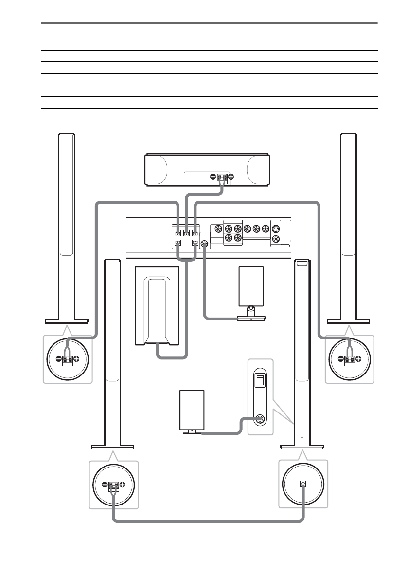
Terminals for connecting the speakers
O
D
Connect the To the
Front speakers SPEAKER FRONT L (white) and R (red) jacks of the system
Center speaker SPEAKER CENTER (green) jack of the system
Subwoofer SPEAKER WOOFER (purple) jacks of the system
Surround speaker (R) SPEAKER (gray) jack of the surround speaker (L)
IR transmitter DIR-T1 (pink) jack of the system
Bottom of the
front speaker
Surround
speaker (R)
Front speaker (R)
Center speaker
SPEAKER
CENTER FRONT LFRONT R
Subwoofer
IR receiver
Use when you do not use
the IR receiver of the
surround speaker (L)
(page 30).
Bottom of the
surround speaker
RL
DIR-T1
SURROUND
RL
BACK
WOOFERWOOFER
Rear side of the
surround speaker (L)
Bottom of the
surround speaker
VIDEO
YP
B/CBPR/CR
AUDIO IN
COMPOMEMT VIDEO OUT
AUDIO IN
SAT
IR transmitter
POWER
ON
OFF
ONLY FOR
DIR-R2
Front speaker (L)
S VIDEO
(DVD ONLY)
VIDEO
MONITOR OUT
ONLY FOR
SS-TS21
SPEAKER
Bottom of the
front speaker
Surround
speaker (L)
with IR receiver
16
US
Page 17
Note on placing speakers
• Do not set the speake r s in a n inc li n ed position.
• Do not place the speakers in locations that ar e:
– Extremely hot or cold
– Dusty or dirty
– Very humid
– Subject to vibrations
– Subject to direct sunlight
• Use caution when placing the speakers on a specially treated (waxed, oiled, polished, etc.) floor, as staining or
discoloration may result.
• Do not lean or ha ng on the spe ak er, as th e spea ke r ma y fall down.
Notes on placing IR transmitter and surround speaker (L) (or IR receiver)
• Do not install the surround speaker (L) (or IR receiver) in a place exposed to direct sunlight or strong light such as
an incandescent la mp.
• The cords of the IR transmitter and IR receiver are for this system only. You cannot use a comm ercially available
extension cord.
Tip for the surround speaker (L)
You can swap the surround speaker (L) and (R) positions, depending on the wall outlet and speaker layout (page 27).
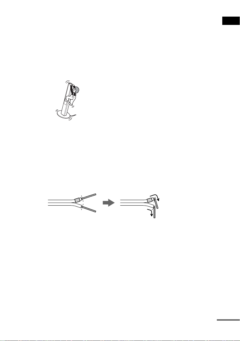
Tip
Connect the speaker cable aft er bendi ng the speak er wire at the en d of the in sulation . This pre vents the speaker ca ble
from being caught in the SPEAKER jack.
Getting Started
continued
17
US
Page 18
To connect the surround back speaker
This system is compatible with the 6.1 surround system. When you enjoy a DVD that is compatible
with the 6.1 surround system such as a DTS-ES disc, connect the surround back speaker (not supplied)
and set its param eters (see “Settings for the Speakers” on page 87).
SPEAKER
CENTER FRONT LFRONT R
VIDEO
B/CBPR/CR
YP
AUDIO IN
RL
DIR-T1
SURROUND
BACK
WOOFERWOOFER
COMPOMEMT VIDEO OUT
RL
AUDIO IN
SAT
S VIDEO
(DVD ONLY)
VIDEO
MONITOR OUT
OPTICAL
DIGITAL IN
AM
FM 75
COAXIAL
SAT
Amplifier
AUDIO
IN
Surround back speaker
Tip
You can also enjoy the 6.1 surround sound when you pl ay a 2 or 5.1 chann el sour c e by using the sur r ound back
decoding function (see “Selecting the Surround Back Decoding Mode” on page 63).
To avoid short-circuiting the speakers
Short-circuiting of the speakers may damage the system. To prevent this, be sure to follow these
precautions w hen conne cting the speakers. Ma ke sure th e bare wire of each spea ker cord do es not tou ch
another speaker jack or the bare wire of another speaker cord.
Examples of poor conditions of the speaker cord
Stripped speaker cord is
touching another speaker
terminal.
Stripped cords are touching
each other due to excessive
removal of insulation.
18
After connectin g al l the components, speakers, an d A C power cord (mains lead), out put a test tone to
check that all the speakers are connected correctly. For details on outputting a test tone, see page 89.
If no sound is heard from a speaker while outputting a test tone, or a test tone is output from a speaker
other than the one currently displayed in the front panel display, the speaker may be short-circuited. If
this happens, check the speaker connecti on again.
Notes
• Be sure to match the speaker cord to the appropr iate term inal on th e componen ts: 3 to 3, and # to #. If the cords
are reversed, the sound will lack bass and may be distorted.
• If you connect the speaker cord incorrect ly o r tur n up the v olum e in a st ate o f a short circui t, “PROTEC T” app ears
in the front panel display and the system e nte r s sta ndby mode. In this case, disconnect and then reconnect the AC
power cord (mains lead) from the wall outlet (mains), and then turn the system on.
US
Page 19
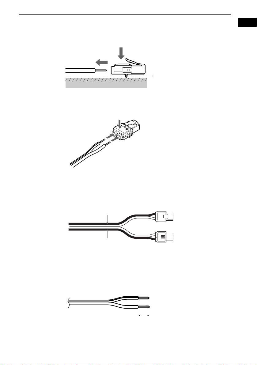
To change the speaker cables
If you want to use a different speaker cable, you can detach the plug for attachment to another cable.
Detaching
Catcher
With the catcher facing down, press and hold the plug down against a flat surface and remove the cords
from plug.
Attaching
While pressing t he plug down against a flat surface, insert the new speaker cords.
Note that the cord marked with a line should be attached to the minus (-) side of the plug.
Notes
• Be careful not to damage the surface you use (desk, etc.) when attaching/detaching the speak er co rd s .
• When using the subwoofer cord, note that the two outside black cords or the cords marked with letters are negative.
(–)
(–)
(+)
Getting Started
(+)
(–)
• If you connect the subwoofer cord incorrectly or turn up the volume in a state of a short circuit, “PROTECT”
appears in the front panel display and the system enters standby mode. In this case, disconnect and then reconnect
the AC power cord (mains lead) from the wall outlet (mains), and then turn the sys t em on.
Tips
• You can use any commercially sold speaker cable of gauge cord AWG #18 - AWG #22.
• Befor e at ta ch ing a new cable, strip off 10 mm (13/32 in.) of its insulation and twist the bare wir e s of bot h co rd s.
10 mm
(–)
19
US
Page 20
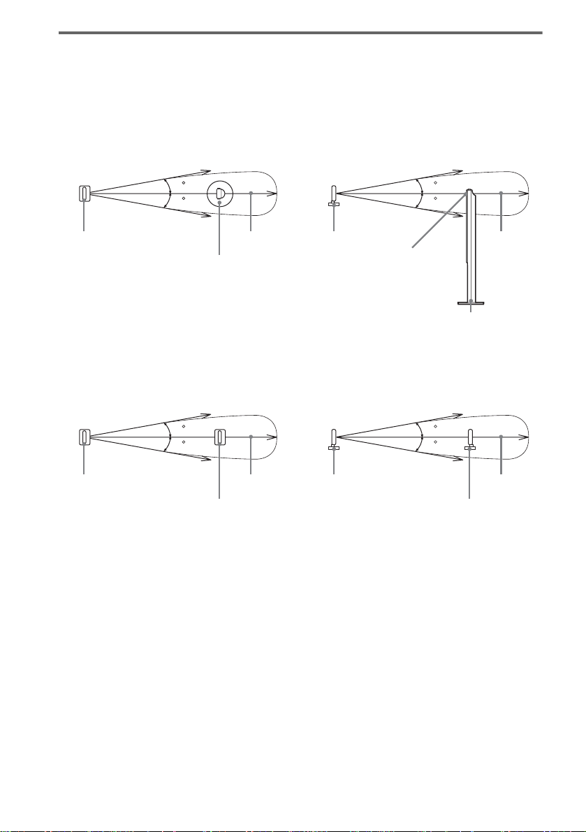
About the wireless system
This wireless system adopts the Digital Infra red Audio Transmission sy stem (page 99). The following
diagram indic at es the infrared transmissi on area (the range that the inf rared rays can reach)
When using the IR receiver of the surround speaker (L)
Top view
IR transmitter
Infrared signal
10
10
Approx. 10m
Surround speaker (L)
Side view
IR transmitter
Infrared signal
10
10
Approx. 10m
IR receiver
Surround speaker (L)
When using the IR receiver
Top view
Infrared signal
10
10
IR transmitter
IR receiver
Notes
Approx. 10m
• Do not install the surround speaker (L) (or IR receiver) in a place exposed to direct sunlight or strong light such as
an incandescent lamp.
• Do not use the surround speaker (L) (or IR recei v er) that is not supplied with the system.
Side view
IR transmitter
Infrared signal
10
10
Approx. 10m
IR receiver
20
US
Page 21
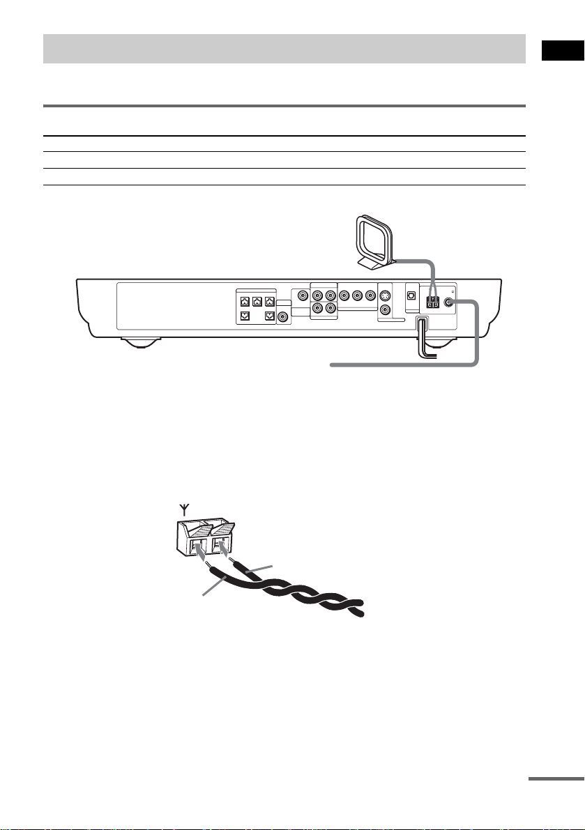
Step 2: Antenna (aerial) Hookups
Connect the supplied AM/FM antennas (aerials) for listening to the radio.
Terminals for connecting the antennas (aerials)
Connect the To the
AM loop antenna ( aerial) AM terminals
FM wire antenna (ae r ial) FM 75Ω COAXIAL jack
AM loop antenna (aerial)
Getting Started
SPEAKER
CENTER FRONT LFRONT R
VIDEO
B/CBPR/CR
YP
AUDIO IN
RL
DIR-T1
SURROUND
WOOFERWOOFER
RL
BACK
AUDIO IN
SAT
COMPOMEMT VIDEO OUT
S VIDEO
(DVD ONLY)
VIDEO
MONITOR OUT
OPTICAL
DIGITAL IN
AM
FM 75
COAXIAL
SAT
FM wire antenna (aerial)
Notes
• To pre ve nt noise pickup, keep the AM loop antenna (aerial) away from the syst em an d othe r com pone nt s.
• B e sure to fully extend the FM wire an te nna (a e rial).
• Afte r con n ecting the FM wire antenna (aerial), keep it as horizonta l as possible.
Tip
When you connect the supplied AM loop ant en na (a eria l), the cord (A) and the cord (B) can be connected in either
terminal.
AM
A
B
continued
21
US
Page 22

Tip
If you have poor FM reception, use a 75-ohms coaxial cable (not supplied) to connect the system to an outdoor
FM antenna (aerial) as shown below.
Outdoor FM
antenna (aerial)
AM
System
FM 75
COAXIAL
22
US
Page 23
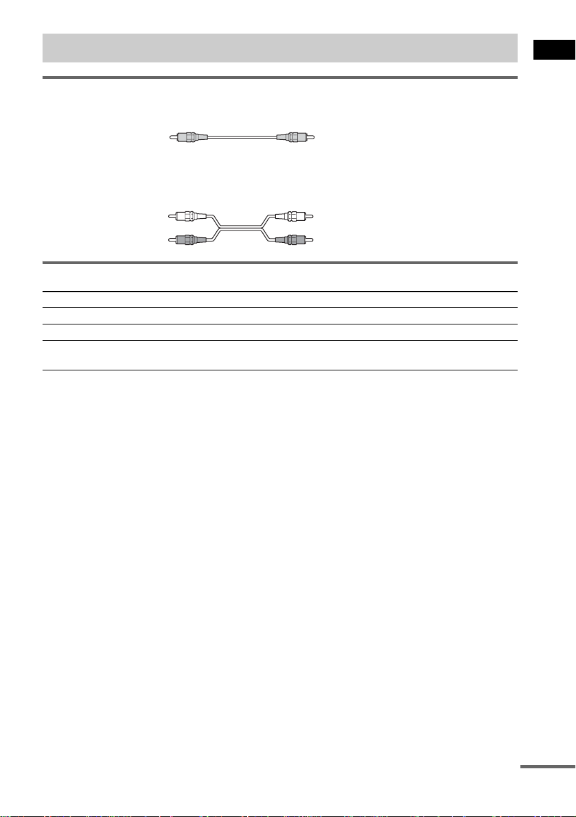
Step 3: TV and Video Component Hookups
Required cords
Video cord for connecting a TV
Yellow
Audio cords (not supplied)
When connectin g a cord, be sure to match the col or-coded sleeves to the ap propriate jacks on the
components.
White (L/audio)
Red (R/audio)
Terminals for connecting video compon ent s
Connect the To the
TV (VIDEO IN) MONITOR OUT (VIDEO) jack
VCR (AUDIO OUT) VIDEO (AUDIO IN) jacks
Digital satellite rec ei ver
(AUDIO OUT)
Notes
• The video signal is output as below:
– When [COMPONENT OUT] is set to [INTERLACE] in [SCREEN SETUP] (page85) (default)
The video signal is output from the S VIDEO and VIDEO jacks of MONITOR OUT.
– When [COMPONENT OUT] is set to [PROGRESSIVE] in [SCREEN SETUP] (page 85)
The video signal is output from the COMPONENT VIDEO OUT jacks only.
• When you connect a VCR or digital satellite receiver to the VIDEO/SAT jacks of this system, change the function
to VIDEO or SAT (page 7 6).
Tips
• Whe n usi ng the S video jack instead of the video jacks, your TV monitor must also be connected via an S video
jack. S video signals are on a separate bus from the video signals and will not be output through the video jac ks.
• When using the COMPONENT VIDEO OUT jacks (Y, P
must also be connected via COMPONENT VIDEO OUT jacks (Y,P
format signals, you must use this connection and set [COMPONENT OUT] to [PROGRESSIVE] in [SCREEN
SETUP] (page 85).
SAT (AUDIO IN) jacks
B/CB, PR/CR) instead of the video jacks, your TV monitor
B/CB, PR/CR). If your TV accepts progressive
Getting Started
continued
23
US
Page 24

TV with COMPONENT
VCR
AUDIO
OUT
L
R
VIDEO IN jacks
Y
PB/CB
PR/CR
OUT
OPTICAL
DIGITAL
OUT
OUT
OUT
AUDIO
OUT
L
R
Digital satellite receiver or
PlayStation 2 etc.
SPEAKER
CENTER FRONT LFRONT R
DIR-T1
SURROUND
BACK
WOOFERWOOFER
IN
VIDEO
IN
TV
IN
VIDEO
B/CBPR/CR
YP
AUDIO IN
RL
COMPOMEMT VIDEO OUT
RL
AUDIO IN
SAT
OPTICAL
S VIDEO
DIGITAL IN
(DVD ONLY)
VIDEO
MONITOR OUT
AM
FM 75
COAXIAL
SAT
IN
S VIDEO
IN
TV with S VIDEO IN jack
Notes
• Make connections securely to prevent unwanted noise.
• Refer to the instructi ons supplied with the TV.
• The system cannot output an audio signal to the connected TV. Only the audio signal of the TV is output from the
system speakers.
If you connect a digital satellite receiver with an OPTICAL OUT jack
The digital satellite receiver can be connect ed to th e SAT OPTICAL DIGITAL IN jack ins tead of the
SAT AUDIO IN (L/R) jacks of the system.
The system can accept bo th the dig ital and an alogue si gnals. Di gital si gnals hav e priori ty over anal ogue
signals. If the digital signal ceases, the analogue signal will be processed after 2 seconds.
If you connect a digital satellite receiver without an OPTICAL OUT jack
Connect the digital satellite receiver to the SAT AUDIO IN (L/R) jacks only of the system.
To listen to the game machine (e.g., PlayStation 2) sound by using the
system
Connect the audio output ja cks of the game machine to the SAT AUDIO IN (L/R) jacks of the system
with the audio cord s (not supplied).
24
US
Page 25

When connecting to a standard 4:3 screen TV
Depending on the disc, the image may not fit your TV sc reen.
If you want to change the aspect ratio, please refer to page 84.
Does your TV accept progressive signals?
Progressive is the method for displaying TV images which reduces flickering, and sharpens the image.
To display using this method, you need to connect to a TV that accepts progressive signals and set the
output signal of COMPONENT VIDEO OUT to the progressive format. For details, see “To set to
[PROGRESSIVE] ” on page 85.
If your TV does not accept progressive signals and progressive format
is set by mistake
The image may not appear, or will appear distorted. In this case, return the setting to interlace format.
.
FUNCTION
1 Press FUNCTION repeatedly until “DVD” appears in the front panel display.
2 While holding down ., press FUNCTION.
The output signal is changed to interlace format.
Getting Started
25
US
Page 26
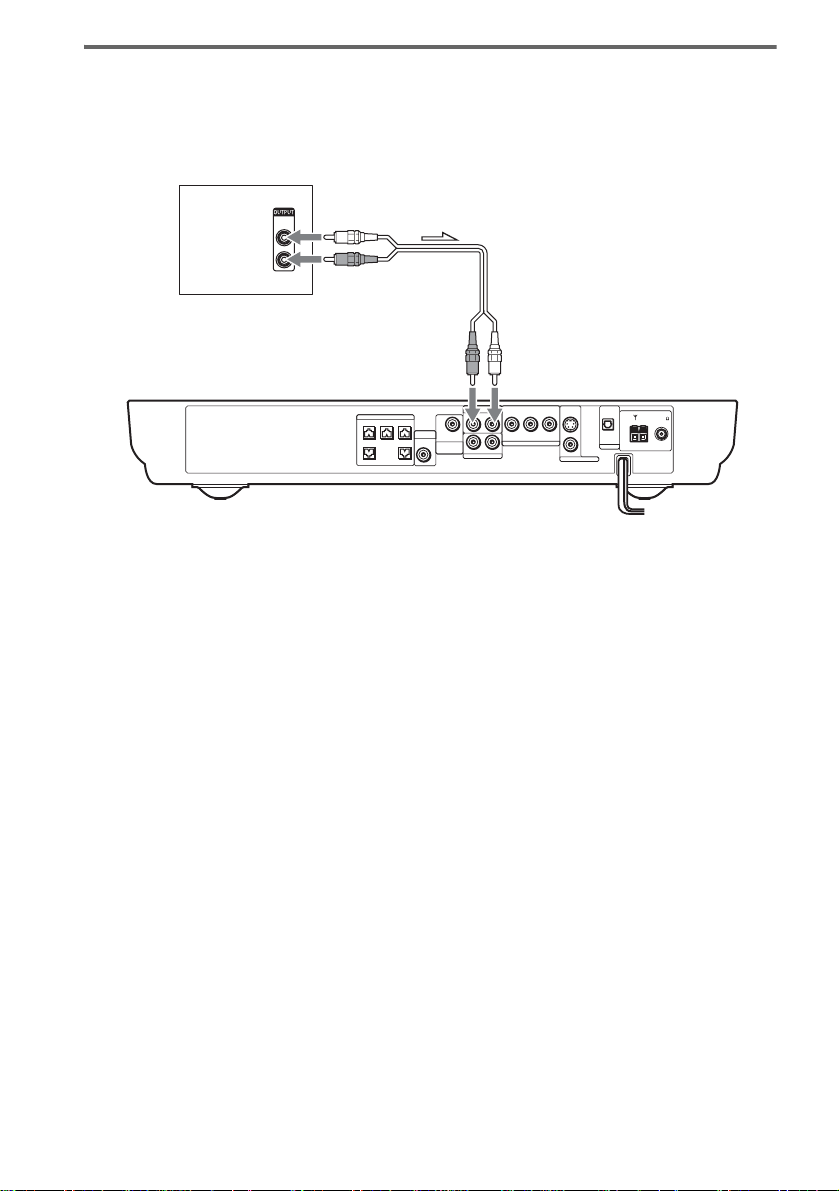
Output the TV or VCR sound from the speakers
Connect audio cords.
1
Connect the AUDIO OUT (L/R) jacks of TV or VCR to the VIDEO jacks (AUDIO IN L/R) of this system
with audio cords.
TV or VCR
*
AUDIO
OUT
L
R
SPEAKER
CENTER FRONT LFRONT R
VIDEO
B/CBPR/CR
YP
AUDIO IN
RL
DIR-T1
SURROUND
BACK
WOOFERWOOFER
COMPOMEMT VIDEO OUT
RL
AUDIO IN
SAT
S VIDEO
(DVD ONLY)
VIDEO
MONITOR OUT
OPTICAL
DIGITAL IN
SAT
AM
FM 75
COAXIAL
* AUDIO OUT (L/R) jacks
If your TV does not have AUDIO OUT (L/R) jacks, you cannot output the TV sound from the speakers of this
system.
2 Change the mode of this system.
Press FUNCTION repeatedly to select “VIDEO.”
Note
Be sure to make the connections se cure ly to avoid hum and noise. If using the VIDEO jack distorts the sound,
reconnect the TV or VCR to SAT.
Tip
When you want to output the TV sound or stereo sound of a 2 channel source from the 6 speakers, select any sound
field other than “AUTO FORMAT DIRECT AUTO” or “2 CHANNEL STEREO” (page59).
26
US
Page 27
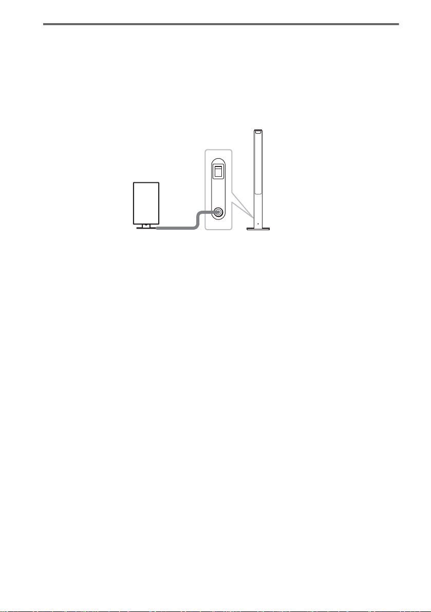
Step 4: Connecting the AC Power Cord (Mains Lead)
Before connecting the AC power cords (mains leads) of this system and the surroun d sp eaker (L) to a
wall outlet (mains), connect the front and center speakers to the system and surround speaker (R) to the
surround speaker (L) (see page 16 ).
When placing the surround
speaker (L) in the (R) position
Depending on the lo cat ion of the wall outlet
(mains), you can also place the surround speaker
(L) (with the IR receiver) in the (R) position if
necessary.
"/1
4 Press X/x repeatedly until “SL SR
REV” appears in the front panel
display, then press ENTER or c.
5 Press X/x repeatedly until the item you
want to set appears in the front panel
display.
xOFF (default)
Sets the surround speaker (L) (with the IR
receiver) in the (L) position.
xON
Sets the surround speaker (L) (with the IR
receiver) in the (R) position.
6 Press AMP MENU.
The AMP menu turns off.
C/X/x/c/
ENTER
Getting Started
AMP MENU
With cover opened.
1 Press "/1 on the system to turn the
system on.
2 Press AMP MENU.
3 Press X/x repeatedly until
“CUSTOMIZE” appears in the front
panel display, then press ENTER or c.
The system enters the Customize Menu
mode.
27
US
Page 28

Step 5: Adjusting the Wireless System
After connecting the speakers, IR transmitter,
and the AC power cords (mains leads), adjust
the wireless system for good tr ansmission.
"/1
IR receiver
POWER
ON
POWER
OFF
ONLY FOR
POWER/ON
LINE indicator
Rear side of the
surround speaker (L)
DIR-R2
1 Press "/1 on the system and POWER
on the surround speaker (L) to turn on.
The system and surround speaker (L) turn
on and the POWER/ON LIN E i ndi c at or
turns red.
2 Orient the IR transmitter and the IR
receiver of the surround speaker (L) to
face each other.
Adjust the position until the POWER/ON
LINE indi c ator turns gree n.
Tip
The IR transmitter is movabl e for easy r e orientation.
Notes
• Make sure that there is no obstruction such as a
person or object between the IR transmitter and the IR
receiver of the surround speaker (L). Otherwise, the
sound from the surround speakers may be interrupted.
• If the POWER/ON LINE indicator turns red, the
transmission is incomplete. Adjust the position of the
IR transmitter and surround speake r (L) unt il the
POWER/ON LINE indicator turns green.
• If the POWER/ON LINE indicator flashes in red, the
IR receiver of the s urround speaker (L) is receiving an
infrared ray from another Sony’s wireless product.
Move the IR transmi tt er and/or the surround s p eak er
(L) so that the POWER/ O N LINE in dicator turns
green.
28
US
Page 29
Example for installation
Position the IR transmitter and surround speaker (L) as illustrated.
Install the IR transmitter and IR rece iver of the surro und speaker (L) in dir ect line with each ot her, and
adjust the orientation of the IR transmitter and surround speaker (L) until the POWER/ON LINE
indicato r turns green.
Top view
Getting Started
IR transmitter
IR receiver of the
surround speaker (L)
Front
speaker (L)
Surround
speaker (L)
Center speaker
TV
Listening position
Front
speaker (R)
Subwoofer
Surround
speaker (R)
29
US
Page 30
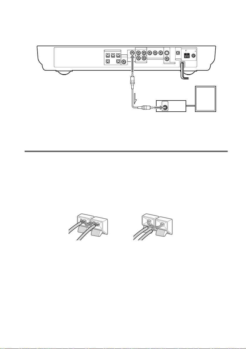
Using the IR receiver
Depending on the speaker layout (i.e. when placin g the surround speaker (L) toward the listening
position, etc.), or when there is obst ru ction, such as a person or object between the IR transmitter and
the IR receiver of the surround speaker (L), you can use the external IR receiver (supplied) instead. The
IR receiver is c om pact and easy to install.
To connect the IR receiver
Connect the cord of th e IR receiver to the DIR-R2 jack of the surround speaker (L).
Rear side of the
surround speaker (L)
POWER
ON
OFF
ONLY FOR
IR receiver
Notes
• When you connect the IR receiver to the surround speaker (L), the IR receiver is activated and the IR receiver of
the surround speaker (L) is not activated automatically.
• When using the IR receiver, install it following the guidelines of the IR receiver of the surround speaker (L).
DIR-R2
30
US
Page 31

Hanging the IR transmitter and IR receiver on a wall
You can hang the IR transmitter and IR receiver on a wall when:
– there is an obstr uction between the IR trans mitter and the IR receiver .
– people often pass between the IR transmitter and the IR receiver.
When hanging both the IR transmitter and IR receiver, adjust the position of the IR transmit ter after
deciding the position of the IR receiver.
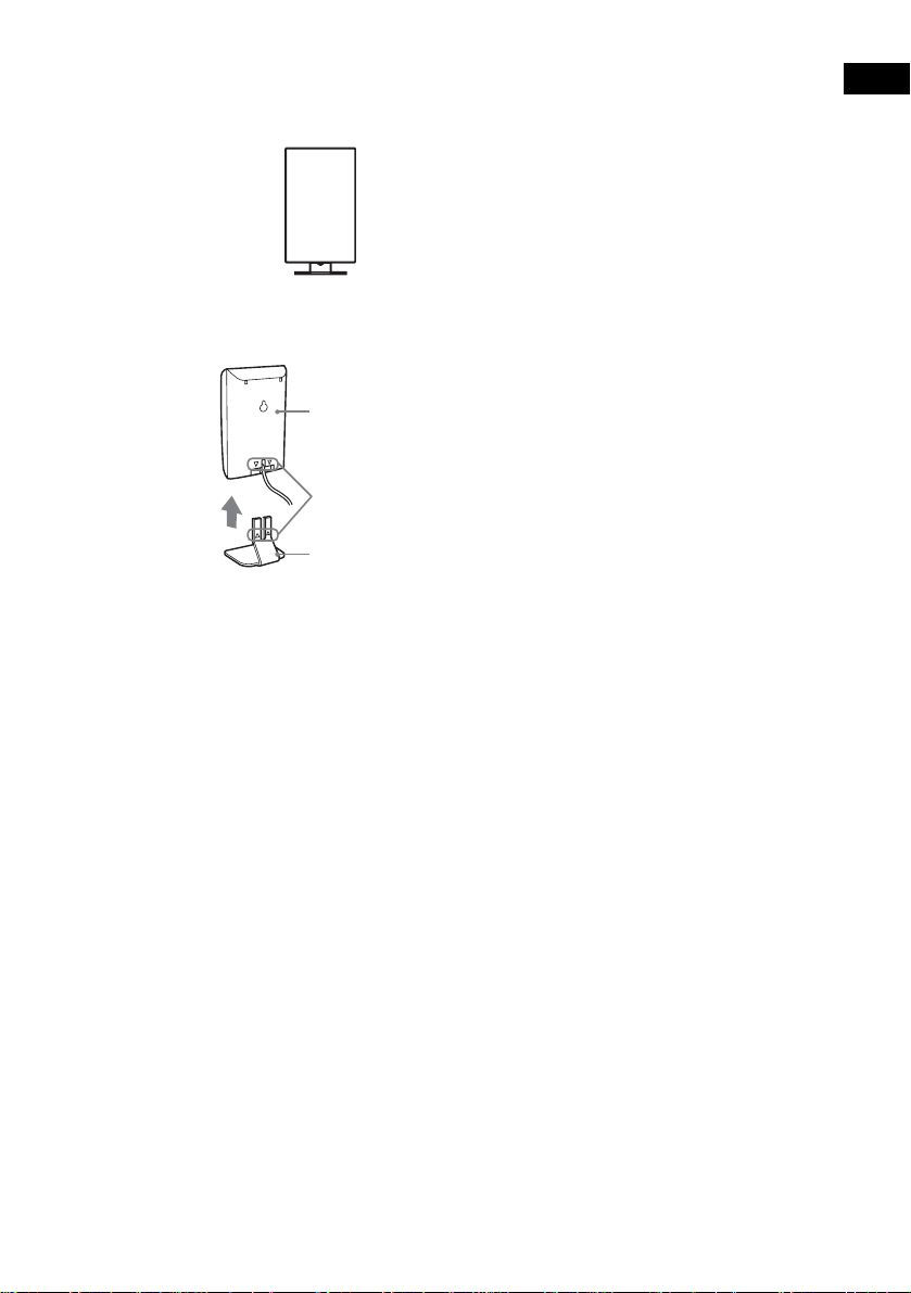
To hang the IR receiver on a wall
1 Install a commercially available screw
in the wall so that it protrudes 4 mm.
4 mm
To hang the IR transmitter on a
wall
1 Rotate the stand of the IR transmitter.
IR transmitter
Stand
2 Detach the IR receiver stand and hang
it via hole on the rear side of the IR
receiver on the screw.
Make sure that the IR receiver does not
move afte r installation .
IR receiver
2 Install 2 commercially available screws
in the wall so that it protrudes 4 mm.
Install the screws 30 mm apart.
30 mm
Getting Started
IR receiver stand
Tip
When reattaching the IR rece iv er stand to the IR
receiver, attach the stand so that both delta marks on
the IR receiver and stand are aligned (page 15).
4 mm
continued
31
US
Page 32

3 Hang the IR transmitter via hole on the
bottom of the stand on the screw.
Make sure that the IR transmitter does not
move after installation.
IR transmitter
Stand
Tip
You can store the cords in the troughs in the bottom of
the stand.
Stand
Notes
• Use screws suitable for the materia l a nd str ength of
the wall.
• Do not install the IR transmitter or IR receiver to a
wall of low strength.
• Sony is not liable for any damage or accident incurred
by incorrect installation (i.e. low strength wall, etc.),
incorrect use of this product, or na tural disaster.
• When connecting/disconnecting cords, detach the IR
transmitter or I R r e ceiver from the wall first.
32
Troughs
US
Page 33

Step 6: Performing the Quick Setup
After completing the first 4 steps, make initial settings using the Quick Setup. You can set the initial
setting of [LANGUAGE SETUP], [ROOM SIZE], [LISTENING POSITION], and [TV TYPE] step by
step.
After performing the Quick Set up, t he syst em is r eady fo r play ing back of movie s, music CDs, etc. To
perform further speak ers settings, see “Settin gs for the Speakers” on page87.
Getting Started
How to use the Quick Setup
"/1
FUNCTION
C/X/x/c/
ENTER
DVD
SETUP
With cover opened.
O RETURN
CLEAR
1 Turn on your TV.
2 Switch the input selector on the TV to
this system.
3 Press "/1.
4 Press FUNCTION to select “DVD.”
The guide message appears on the TV
screen.
Note
When a disc is in the system, the guide message
does not appear on the TV screen.
5 Press ENTER.
[LANGUAGE SETUP] appears.
LANGUAGE SETUP
ENGLISH
FRENCH
SPANISH
PORTUGUESE
Notes
• The selectable language is different depending
on the area.
• The language you select in [LANGUAGE
SETUP] is also used for [OSD], [DVD MENU],
and [SUBTITLE] (page 84).
6 Select a language using X/x, then
press ENTER.
Setting is selected and [ROOM SIZE]
appears.
ROOM SIZE
FRONT:
ft
m
1 . 5
SMALL
5
SURROUND:
ft
5
1 . 5
m
continued
33
US
Page 34

7 Select a suitable room size from
[SMALL], [MEDIUM], or [LARGE] using
X/x, then press ENTER.
Setting is selected and [LISTENING
POSITION] appears.
LISTENING POSITION
FRONT:
ft
m
5
1 . 5
SURROUND:
ft
m
5
1 . 5
The [LISTENING POSITION] numbe r you
can select va ries, depe nding on th e [ROOM
SIZE] setting.
[SMALL]: Three positions
[MEDIUM]: Four positions
[LARGE]: Five positions
8 Select a suitable listening position
X/x, then press ENTER.
using
Setting is selected and [TV TYPE] appears.
TV TYPE
4 : 316 : 9
Notes
• Whe n you press CLEAR in guide message, the
message disappears. When you nee d to ch an ge
settings, select [QUICK] from [SETUP] in Setup
Display (page 93).
• When you select [4:3] in [TV TYPE], [4:3 LETTER
BOX] is selected (page 84).
• The distance and level of each speaker will be set
automatically ac cording to the selection of [ROOM
SIZE] and [LISTENING POSITION] (page 87).
• If you want to change each setting, see “Using the
Setup Display” on page 83.
• The illustrations displayed for [ROOM SIZE] and
[LISTENING POSITION] are only examples and
may differ from the actual room siz e and layout.
The settings for [SPEAKER SETUP] (page87) do
not appear on these displays.
34
9 Select a TV type connecting to the
system using
The Quick Setup is complete.
When the Quick Setup is completed, the
settings are saved and the guide me ssage
will not appear the next time you turn on the
system.
If you make a mistake
Press O RETURN, then select the item again.
To quit the Quick Setup
Press DVD SETUP in an y Step.
US
C/c, then press ENTER.
Page 35

Speaker Setup
Positioning the speakers
For the best possib le surround sound, all the
speakers other than the subwoofer should be the
same distance from the listening position (A).
However, this system allows you to place th e
center speaker up to 1.6 meters (5 ft)a) closer
(B) and the surround speakers up to 4.6 meters
(15 ft)b) closer (C) to the listening position.
The front speakers can be placed from 1.0 to
7.0 meters (3 to 23 ft)c) (A) from the listening
position.
North American numerical equivalents:
a) 5 feet (1.5 meters)
b) 15 feet (4.5 meters)
c) 3 to 23 feet (0. 9 t o 6.9 meters)
Place speakers as i ll us trated below
About magnetically shielded
speakers (to prevent color
irregularity occurring on the TV
screen)
The subwoofer in this system is magnetically
shielded to prevent magnetic leak age. However,
some leakage m ay occur, as a high-strength
magnet is employed. If the subwoofer is used
with a CRT-based TV or projector, install the
subwoofe r at least 0.3 meter (1 ft) from the TV
set. If it is installed too close, color irreg ul ar ity
may occur on th e screen. If color irregula ri ty
occurs, turn off the TV set once, then turn it on
after 15 to 30 minutes. If color irregularity
occurs again, pl ace the subwoofer farther aw ay
from the TV set. If color irre gulari ty st ill occur s
after performi ng t he above, make sure that no
magnetic object is pl aced near the subwoofer.
Color irregularity may occur as a result of
interaction be tween the subwoofer and the
magnetic object .
Examples of possible sources of magneti c
interference include: magnetic latches on a TV
stand, etc., healt hcare devices, toys, etc.
Specifying the speaker
parameters
Getting Started
Notes
• Do not place the center and surround speakers farther
away from the listen ing position than the front
speakers.
• Whe n you c onne c t an o ptional surround back
speaker, place the surround back speaker beh ind the
listening position (p lace (D) as i llus trat ed a bove). I n
this case, set [SURROUND BACK] to [YES] in the
[SIZE] setting (page 87) to output sound from the
surround back speaker.
To obtain the be st possib le surrou nd sound, first
specify the dist ance of the speakers from your
listening position, then set the leve l and balance.
Use the test tone to adjust the speaker level a nd
balance to the same level.
Select [SPEAKER SETUP] in the setup display.
For details, see “Settings for the Speakers”
(page 87).
35
US
Page 36

Playing Discs
Playing Discs
Depending on the DV D or VID E O CD, some
operations may be different or restricted.
Refer to the operation details supplied with your
disc.
Disc slot
"/1
STANDBY indicator
DISC SKIP
Disc1-5/Z/
indicators
H
FUNCTION
Adjust the
volume
Connect
headphones
"/1
FUNCTION
4 Press DISC1–5 Z.
Press the Z button of the disc number you
want.
“NO DISC” appears in the front panel
display and the system is ready for
loading the disc.
Example: Whe n you want to load the disc to
the disc stocker 1, pr ess DISC1 Z.
If there is a disc in th e stocker that you
select, the disc is ejected, “NO DISC”
appears in the fron t p anel display, then the
system is ready for loading the disc.
5 Load a disc.
Push the disc into th e disc slot unt il the disc
is pulled in automatically.
The disc is drawn into the system
automatically an d “R EADING” appears in
the front pane l di splay.
With the playback side facing down
36
1 Turn on your TV.
2 Switch the input selector on the TV to
this system.
Press "/1 on the system.
3
The system tur n s on.
Unless th e mode of the system is set to
“DVD,” press FUNCTION to select
“DVD.”
“NO DISC” appears in the front panel
display and the syst em is rea dy for loading
the disc.
US
To load other discs, press DISC1-5 Z (that
is not loaded a disc ) and load the disc after
“NO DISC” appears in the front panel
display.
6 Press H on the remo t e or on the
system.
The system starts playback (continuous
play) of the disc whose DISC indicator is
green.
To play back ot he r di scs, pr es s DIS C SKIP
on the remote or DIS C 1-5 of the system.
Adjust the volume on the system.
Page 37

After following Step 6
Depending on the disc, a menu may appear on
the TV screen. You can pl ay the disc
interactively by followin g the instructions on the
menu. (DVD: page 39), (VIDEO CD: page 39).
To remove the disc
Press DISC1-5 Z on the system. Remove the
disc after it is ejected from the system. “NO
DISC” appears in t he front panel display.
To turn on the system
Press "/1 on the system. The syste m turns on. In
standby mode, the system also turns on by
loading a disc.
To turn off the system
Press "/1. The system enters standby mode and
the STANDBY indicator lights up in red. To
turn off the system completely, remove the AC
power cord (mains lead) from the wall outlet
(mains).
While playing a disc, do not turn off the system
by pressing "/1. Doing so may cancel the menu
settings. When you turn off the system, first
press x to stop pl ayback and then press "/1.
Tip
The DISC1-5 indicators change their colors as follows:
– green: the disc is chosen, or the disc is being play
backed.
– off: there is no disc.
– orange: a disc is loaded to the disc stocker,
however, the disc is not chosen.
To save the power in standby
mode
Press "/1 while the system turns on (the
STANDB Y indicator on the system ligh ts up).
To cancel standby mode
Press "/1 once.
Additional operations
DISC SKIP
./>
H
To Press
Stop x
Pause* X
Resume play from pause X or H
Go to the next chapter,
track, scene, or file in
continuous play mode
Go back to the preceding
chapter, track, scene , o r f il e
in continuous play mode
Mute the sound MUTING. To cancel
Change a disc while playing
another disc
Play the desired disc directly DISC1-5 on the
Stop play a n d remove the
desired d isc
* You cannot pause during JPEG playback.
Notes
• If there is no disc in the system, “NO DISC” appears
on the front panel display.
• If DVD playback is paused for approximately one
hour, the system automatically turns off.
Tip
If a DVD has more than two titles, you cannot go to the
next title or go back to the preceding title by pressing
. or >. These buttons work only within a single
title. If you want to go to the n ex t title or go back to
preceding title, press DVD TOP MENU or DVD
MENU and then select the title you want to go to from
the control menu.
X
x
MUTING
VOL +/–
>
.
muting, press it again
or VOL + to adjust the
sound volume.
DISC SKIP
system.
DISC1-5
Z on the
system.
Playing Discs
37
US
Page 38

Resuming Playback from
the Point Where You
Stopped the Disc
(Resume Play)
When you stop th e disc, the system remembers
the point whe re yo u pr essed x and “RESUME”
appears in the front panel display. As long as
you do not remove the disc, Resume Play will
work even if the system enters standby mode by
pressing "/1.
Tip
To play from the beginning of the disc, press x twice,
then press H.
H
x
1 While playing a disc, press x to stop
playback.
“RESUME” appe ars in the front panel
display, so you can restart the disc from the
point where you sto pped the disc.
If “RESUME” does not appear, Resume
Play is not available .
2 Press H.
The system starts pl ayback from the point
where you stoppe d th e disc in Step 1.
Notes
• Y ou cannot perform Resume Play during Shuffle
Play or Program Play.
• Depending on where you stop the disc, the system
may not resume playback from e xa ct ly the sa me
point.
• The point where you stopped playing is cleared if:
– you change the play mode.
– you change the setting on the Setup Me nu.
38
US
Page 39

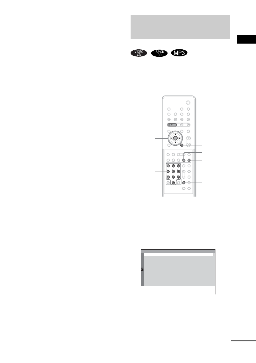
Using the DVD’s Menu
Playing VIDEO CDs with
PBC Functions (Ver. 2.0)
A DVD is divided into a lot of sections, which
make up a picture or music feature . These
sections are called “titles.” When you play a
DVD which contains several titles, you can
select the title you want using DVD TOP
MENU/ALBUM–.
When you play DVDs that allow you to select
items such as the language for the subtitles and
the language for th e sound, select these items
using DVD MENU/ALBUM+.
DVD TOP
MENU/
ALBUM–
C/X/x/c/
ENTER
Number
buttons
With cover opened.
DVD MENU/
ALBUM+
1 Press DVD TOP MENU/ALBUM– or DVD
MENU/ALBUM+.
The disc’s menu ap pears on the TV screen .
The contents of the menu vary from disc to
disc.
2 Press C/X/x/c or the number buttons to
select the item you want to play or
change.
3 Press ENTER.
Note
If the DVD top menu or a DVD menu is displayed
during DVD playback for approximately one hour, the
system automatically turns off.
(PBC Playback)
With PBC (Playback Cont r ol ) f unc tions, you
can enjoy simple interactive operations, search
functions, an d other such opera t i ons.
PBC playback allow s you to play VIDEO CDs
interactively by following the menu on the TV
screen.
./>
H
X/x/
ENTER
Number
buttons
With cover opened.
x
O RETURN
1 Start playing a VIDEO CD with PBC
functions.
The menu for your selection appears.
2 Select the item number you want by
pressing X/x or the number buttons.
3 Press ENTER.
4 Follow the instructions in the menu for
interactive operations.
Refer to the operation details s upplied wit h
the disc, as the operating procedure may
differ, depending on the V IDEO CD.
To go back to the menu
Press O RETURN.
Playing Discs
continued
39
US
Page 40

Notes
• D ep end ing on the VIDEO CD , the me nu doe s not
appear in Step 1.
• Depending on the VIDEO CD, “Pr ess ENTER” in
Step 3 may appear as “Press SELECT” in the
instructions supplied with the disc. In this case, press
H.
Tip
To play without using PBC, press ./> or the
number buttons while the system is stopped to select a
track, then press H or ENTER.
“Play without PBC” appears on the TV screen and the
system starts continuous play. You cannot play still
pictures such as a menu. To return to PBC playba ck ,
press x twice, then press H.
Playing an MP3 Audio
Track
You can play MP3 audio tracks on CD-ROMs,
CD-Rs, or CD-RWs. However, the discs must be
recorded according to ISO9660 level 1, level 2,
or Joliet format for the system to recognize the
tracks. You can also play discs record ed in Multi
Session. See the instructions of the CD-R/RW
device or record i ng software (not supplied ) for
details on the record ing format.
1 Load a data disc recorded in MP3 into
the system.
2 Press H.
The system starts to play the first MP3
audio track in the first album on the disc.
Notes
• The system can play MP3 (MPEG1 Audio Layer3)
audio. The system cannot play audio tracks in
MP3PRO format.
• Th is system can play Multi Session CDs when an
MP3 audio track is located in the first session. Any
subsequent MP3 audio tracks, re corde d in the later
sessions, can also be played back.
• Maximum number of albums on a disc: 99 (The
maximum number of MP3 audio tracks that can be
contained on an album is 250.)
• An album that does not include an MP3 audio track is
skipped.
• If y ou put the extension “.MP3” to data not in MP3
format, the system cannot recognize the data properly
and will generate a loud noise which could dama ge
your speaker system.
• If the system cannot play MP3, set [DATA CD
PRIORITY] to [MP3] in the [CUSTOM SETUP]
setting (page 87).
• Th e sys te m can play to a depth of 8 directories,
including a root directory.
40
US
Page 41

Selecting an album and track
DVD TOP
MENU/
ALBUM–
DVD
DISPLAY
DVD MENU/
ALBUM+
C/X/x/c/
ENTER
O RETURN
1 Press DVD DISPLAY.
The Control Menu and name of the MP3
data disc appears.
2 Press X/x to select (ALBUM)
then press ENTER or c.
The list of albums contai ned in the disc
appears.
3:HOME TOWN
ROCK BEST HIT
KARAOKE
JAZZ
R&B
MY FAVORITE SONGS
CLASSICAL
SALSA OF CUBA
BOSSANOVA
MP3
3 Select an album you want to play using
X/x and press ENTER.
4 Select (TRACK) using X/x
and press ENTER.
The list of tracks contained in the current
album appears.
3:HOME TOWN
ROCK BEST HIT
HIGHWAY1.
2.
VIEW POINT
3.
MY CHILDREN
4.
DANCING
5.
GOOD TASTE
6.
DESTINATION
7.
MARATHON
8.
PLACE-KICK
9.
TAKE IT EASY
10.
PORT TOWER
11.
STANDARD
MP3
When the list of all tr acks or al bums c annot
be displayed on th e w indow, the jump bar
appears. Pres s c to select the jump ba r icon,
and then scroll the jump bar to display the
rest of the list using X/x. Press C or
O RETURN to return to the track or the
album list.
5 Select a track using X/x and press
ENTER.
The selected track starts playing.
To return to the previous display
Press O RETURN or C.
To turn off the display
Press DVD DISPLAY.
Notes
• Only alphabetical letters and numbers can be used for
album or track names. Anything else is displayed as
“ ”.
• If the MP3 file you play back has an ID3 tag, the ID3
tag information is displ ayed as a track name.
• ID3 tag applies only to version 1.
• If an MP3 file of VBR (va ri able bit rate) is played,
indicated elapsed time may be different from the
actual time .
• Until playing the disc or selecting an album in step 2,
album name is displayed as “**Album” (** refers to
a number) in the Control Menu, after which the album
name is displayed.
Tip
When an MP3 data disc is inserted, you c an sele c t a n
album using the DVD MENU/ALBUM+ or DVD TOP
MENU/ALBUM– on the remote.
Playing Discs
41
US
Page 42

Playing JPEG Image Files
Selecting an album and file
You can play JPEG image files on CD-ROMs,
CD-Rs, or CD-RWs. However, the disc s must be
recorded accordi ng to ISO9660 level 1, level 2
or Joliet format for the system to recognize the
files. You can als o pl ay discs recorded in Multi
Session. See the instructions of the CD-R/RW
device or recording software (not supplied) for
details on the recording format.
1 Load a data disc recorded in JPEG into
the system.
2 Press H.
The system starts to play the first JPEG
image file in the first album on the disc.
Notes
• The system can play the extension “.JPG” or
“.JPEG.”
• The system can play Multi Session CDs.
• An album that does not include a JPEG file is
skipped.
• If the syst em cannot play JPEG, set [DATA CD
PRIORITY] to [JPEG] in the [CUSTOM SETUP]
setting (page 87).
• A JPEG image file of a length or width of more than
4,720 dots cannot be played.
• A JPEG im a ge file with a hi gh widt h to le ngth ratio
cannot be displayed.
• Some CD-Rs or CD-RWs cannot be played on thi s
system depending on f ile format.
• T he syste m can pla y to a depth of 8 directories,
including a root directory.
• Progressive JPEG image files cannot be played on
this system.
• Maximum number of albums on a disc: 99
(The maximum number of JPEG image files that can
be contained on an album is 250.)
Tip
When you go to the next file or to go back to the
previous file, press . or >.
DVD TOP
MENU/
ALBUM–
DVD
DISPLAY
DVD MENU/
ALBUM+
C/X/x/c/
ENTER
O RETURN
1 Press DVD DISPLAY.
The Control Menu and name of the JPEG
data disc appe ars.
2 Press X/x to select (ALBUM)
then press ENTER or c.
The list of albums contained in the disc
appears.
2:MOUNTAIN
FAMILY
FLOWER
GARDEN
TRAIN
CAR
JPEG
3 Select an album you want to play using
X/x and press ENTER.
4 Select (FILE) using X/x and
press ENTER.
The list of files contained in the current
album appear s.
2:MOUNTAIN
FAMILY
HAPPY1.
2.
BIRTHDAY
3.
CELEBRATION
4.
CHRISTMAS
5.
MOM
6.
BASEBALL
7.
PARTY
8.
DAD
9.
TRAVEL
10.
FRIEND
11.
DRIVE
JPEG
42
US
Page 43

When the list of all files or albums cannot
be displayed on the window, the jump bar
appears. Press c to select the jump bar icon,
and then scroll the jump bar to display the
rest of the list using X/x. Press C or
O RETURN to return to the file or the
album list.
5 Select a file using X/x and press
ENTER.
The selected file starts playing.
To return to the previous display
Press O RETURN or C.
To turn off the display
Press DVD DISPLAY.
Notes
• Only alphabetical letters and numbers can be used for
album or file names. Anything else is displayed as “ ”.
• Until playing the disc or selecting an album in step 2,
album name is displayed as “**Album” (** refers to
a number) in the Control Menu, after which the album
name is displayed.
Tip
When a JPEG data disc is inserted, you can select an
album using the DVD MENU/ALBUM+ or DVD TOP
MENU/ALBUM- on the remote.
Enjoying Slide show on a
JPEG data disc
Playing Discs
M
H
1 Press M while displaying a JPEG
image.
Slide show starts from the current image.
2 Press H when you want to exit Slide
show.
Return to normal play from the current
image.
To change the interval time of
Slide show
Each time you press M during Slide show, the
interval time changes. With each press, the
indication changes as follows:
1M t 2M t 3M
t
The 3M interval time is faster than 2M.
Note
Slide show can play in only one direction .
43
US
Page 44

To rotate the current image
Selecting the Play Mode
(All Discs, One Disc, or Album)
H
C/c
Rotate the current image using C/c.
Each time you press c, the image turns
clockwise by 90º.
Each time you press C, the image turns
anticlockw i se by 90º.
Note
You cannot rotate the image during S lide show. Press
H to return to normal play before this operation.
You can select the play mode that plays all discs
continuously, one disc, or album.
C/X/x/c/
ENTER
DVD
DISPLAY
With cover opened.
O RETURN
PLAY MODE
1 In stop mode, press DVD DISPLAY.
2 Press X/x to select (PLAY
MODE), then press ENTER or c.
3:HOME TOWN
ROCK BEST HIT
(
)
1 5
CONTINUE(ALL)
CONTINUE(ONE)
CONTINUE(ALBUM)
SHUFFLE(ALL)
SHUFFLE(ONE)
SHUFFLE(ALBUM)
PROGRAM
MP3
44
US
Page 45
ALL/ONE/ALBUM
• ALL: The system plays all discs in the system
consecutively in the order of the disc slot
number, and you can set Shuffle Play or
Repeat Play for all the discs.
• ONE: The system plays only the one disc you
have selected, and you can set Shuffle Play or
Repeat Play for 1 disc only.
• ALBUM (MP3/JPEG only): The system plays
tracks/files in t he Album that is contain ed on a
MP3/JPEG disc , and you can set Shuf fle Play
or Repeat Play fo r t h e A l bum. When the disc
except an MP3/ JP EG di sc is played, the
system plays the disc in ONE play mode.
To return to the previous display
Press O RETURN or C.
To turn off the display
Press DVD DISPLAY.
Tip
You can select the play mode directly by pres sing
PLAY MODE. Each time you press the button, the
play mode changes.
Creating Your Own
Program
(Program Play)
You can play the co nt ents of a disc in the order
you want by ar rangi ng t he orde r of th e tr acks o n
the disc to create your own program. You can
program up to 25 tracks.
H
C/X/x/c/
ENTER
Number
buttons
ORETURN
REPEAT
PLAY
MODE
CLEAR
Playing Discs
With cover opened.
1 In stop mode, press PLAY MODE
repeatedly until “PGM” appears in the
front panel display.
The Program Men u appears on the TV
screen.
Program
1
2
3
4
5
6
7
8
9
10
continued
45
US
Page 46

To check the tracks or albums that you have
already created once, press C to select the
jump bar icon, and then scroll the jump bar
to display the rest of the list using X/x.
Press c or O RETURN to return to the
track list.
You can select the jump bar icon only if
there are more than 9 programmed tracks or
albums.
2 Press c, then press X/x to select the
disc.
Program
1
Disc
2
DISC1(CD)
3
DISC2(CD)
4
DISC3(CD)
5
DISC4(CD)
6
DISC5(CD)
7
8
9
10
3 Press c.
The cursor moves to the track (in this case,
“1”). Before programming the MP3 tracks,
it is required to select the album.
Program
1
Disc
2
DISC1(CD)
Track
3
DISC2(CD)
ALL
ALL TRACKS
4
DISC3(CD)
1
TRACK1
5
DISC4(CD)
2
TRACK2
6
DISC5(CD)
TRACK3
3
7
TRACK4
4
8
TRACK5
5
9
TRACK6
6
10
7
8
9
TRACK7
TRACK8
TRACK9
To select a track that is not displayed on the
window, press c to select t he jump bar icon,
and then scroll the jump bar to display the
rest of the list using X/x. Press C or
O RETURN to return to the track list.
You can select the jump bar icon only if
there are more than 9 tracks.
4 Select the track you want to program.
For example, select track “7.”
Program
1
Disc
2
DISC1(CD)
Track
3
DISC2(CD)
ALL
ALL TRACKS
4
DISC3(CD)
1
TRACK1
5
DISC4(CD)
2
TRACK2
6
DISC5(CD)
3
TRACK3
7
4
TRACK4
8
5
TRACK5
9
6
7
8
9
TRACK6
TRACK7
TRACK8
TRACK9
10
5 Press X/x or the number buttons to
select “7” then press ENTER.
Program
1
DISC1(CD)-TRACK7
2
3
4
5
6
7
8
9
10
6 To program other tracks, repeat Steps
2 to 5.
The programmed tracks are dis played in the
selected order.
7 Press H to start Program Play.
Program Play begins.
When the program ends, yo u can restar t the
same program again by pressing H.
To return to normal play
In stop mode, press PLAY MODE repeatedly
until “ALL DISCS” or “1 DISC” appears in the
front panel display.
Other Operations
To Do this
Turn off the
Program Menu
Cancel the
programmed
order
Note
Program Play function is not available for DVDs and
JPEG.
Tip
You can perform Repeat Play of programmed tra ck s.
Press REPEAT, o r set [ RE P E A T] to [ALL] in the
Control Menu display during Program Play (page 48).
In stop mode, press PLAY MODE
to turn off the Program Menu.
Press CLEAR in Step 5, and the
last program is cancelled one by
one.
46
US
Page 47

Playing in Random Order
(Shuffle Play)
You can have the system “shuffle” tracks and
play them in random order. Subsequent
“shuffling” will produce a different playing
order.
Setting the shuffle mode in
the Control Menu
You can select eit her normal shuffle or album
shuffle (MP3 only).
H
Playing Discs
H
PLAY
MODE
With cover opened.
1 In stop mode, press PLAY MODE
repeatedly until “SHUF” appears in the
front panel di s pl a y .
You can play all tracks on all discs in a
random order, or all tracks on the specific
disc in a random order.
When you play an M P3 di sc, you can play
all tracks in album s i n random order.
For details on album shuffle, see page
47.
2 Press H.
To return to normal play
In stop mode, press PLAY MODE repeatedl y
until “SHUF
display (SHUFFLE cancelled). The same
applies to cancel SHU FFLE (ALBUM).
” disappears from t he front panel
DVD
DISPLAY
C/X/x/c/
ENTER
1 Press DVD DISPLAY.
The Control Menu a ppears.
2 Press X/x to select (PLAY
MODE), then press ENTER or c.
3:HOME TOWN
ROCK BEST HIT
(
)
1 5
CONTINUE(ALL)
CONTINUE(ONE)
CONTINUE(ALBUM)
SHUFFLE(ALL)
SHUFFLE(ONE)
SHUFFLE(ALBUM)
PROGRAM
3 Select [SHUFFLE (ALL)], [SHUFFLE
(ONE)], or [SHUFFLE (ALBUM)] using
X/x and press ENTER.
[SHUFFLE (ALL)]: Plays all tracks on all
discs in random or der.
[SHUFFLE (ONE)]: Plays tracks on the
disc in random or der.
[SHUFFLE (ALBUM)]: Plays tracks from
a selected album i n random order.
4 Press H.
The selected Shuffl e Play begins.
MP3
continued
47
US
Page 48

Note
While shuffling all discs, you cannot operate DISC
SKIP on the remote or DISC1-5 on the system.
Playing Repeatedly
(Repeat Play)
You can play all the titl es/tra cks/fi les or a sin gle
title/chapter/track on a disc.
In Shuffle or Program Play mode, the system
repeats tracks i n shuffled or programmed or der.
You cannot perform Repeat Play during PBC
playback of VIDEO CD s (page 39).
H
C/X/x/c/
ENTER
DVD
DISPLAY
REPEAT
48
With cover opened.
1 Press DVD DISPLAY.
The Control Menu appears.
2 Press X/x to select
(REPEAT), then press ENTER or c.
If you do not select [OFF ], th e [REPEAT]
indicator lights in green.
3 Select the Repeat Play setting, then
press ENTER.
1:DVD
1 2 ( 2 7 ) TITLE12
)
1 8 ( 3 4
T
1 : 3 2 : 5 5
OFF
ALL
TITLE
CHAPTER
US
DVD
Page 49

x When playing a DVD
•OFF: does not play repeatedly.
• ALL: repeats all the titles (except
SHUFFLE (ALL)).
• TITLE: repeats the current title on a
disc.
• CHAPTER: repeats the current
chapter.
x When playing a VIDEO CD/Super
Audio CD/CD/MP3, and when Program
Play is set to OFF
•OFF: does not play repeatedly.
• ALL: repeats all the tr acks on the disc,
or repeats the cur rent album (only
when CONTINUE (ALBUM) or
SHUFFLE (ALBUM) in the play
mode is selected) (except SHUFFLE
(ALL)).
• TRACK: repeats the current track.
x When playing a JPEG
•OFF: does not play repeatedly.
• ALL: repeats all the files on the disc
(when CONTINUE is selected in the
play mode), or repeats the current
album (when CONTINUE (ALBUM)
is selected in the play mode).
x When Program Play is set to ON
•OFF: does not play repeatedly.
• ALL: repeats Program Play.
Notes
• Depending on the DVD disc, Repeat Play does not
work.
• If [ALL] is selected, Repeat Play is limited to 5 times.
Tips
• You can set Repeat Play during stop mode.
After selecting th e [ REPEAT] item, press H.
The system starts Repeat Play.
• You can quickly display the [REPEAT] status.
Press REPEAT on the remote.
• You can perform Repeat Play for DVD titles that
contain chapters.
Searching for a Particular
Point on a Disc
(Scan, Slow-motion Play)
You can locate a particular point on a disc
quickly by m on i t oring the picture or by playing
back slowly.
SLOW /
H
Notes
• Depending on the DVD/VIDEO CD, you may not be
able to perform some of the operations described.
• During Scan or Slow-motion Play, no sound is
output.
m/M
Locating a point quick ly by
playing a disc in fast forward
or fast reverse (Scan)
1 Press m or M while playing a disc.
2 When you find the point you want,
press H to return to normal speed.
Playing Discs
continued
49
US
Page 50

To change the scan speed (DVD/
VIDEO CD only)
Each time you pr ess m or M during scan, the
playback speed changes. Two speeds are
available. With each press, the indication
changes as foll ows:
Searching for a Title/
Chapter/Track/Index/
Album/File
Playback direction
1M t 2M
t
Opposite dire ction
1m t 2m
t
The 2M/2m playback speed is faster than
1M/1m.
Watching fram e by frame
(Slow-motion Play)
(DVD/VIDEO CD only)
Press or when the system is in the
pause mode.
To return to normal speed, press H.
To change the speed of Slowmotion Play
Each time you press or during Slowmotion Play, the pla yback speed changes. Two
speeds are avail abl e. With each press, the
indication changes as follows:
Playback direction
2 t 1
t
Opposite direction (DVD only)
2 t 1
t
The 2 /2 playback speed is slower than
1/1.
You can search a title (DVD), chapter (DVD),
track (CD, VIDEO CD, Super Audio CD, MP3),
index (VIDEO C D , S uper Audio CD), album
(MP3, JPEG), and file (JPEG). As titles, tracks
albums and files ar e assigned unique names on
the disc, you can select the desired one from the
Control Menu. A ls o chapters and indexes are
assigned unique numbers on the disc, so you
select the desired one by entering its number. Or
you can search a particular point using the time
code (TIME SEARCH).
You cannot search a scene of a VIDEO CD
(when the PBC fun ct i on i s on).
C/X/x/c/
ENTER
DVD
DISPLAY
Number
buttons
With cover opened.
ORETURN
CLEAR
Searching for a title/track/
album/file
1 Press DVD DISPLAY.
The Control Menu appears.
2 Press X/x to select the search method,
then press ENTER or c.
50
US
Page 51

x When playing a DVD
(TITLE)
x When playing a VIDEO CD
(TRACK)
x When playing a Super Audio CD
(TRACK)
x When playing a CD
(TRACK)
x When playing an MP3
(ALBUM) or
(TRACK)
x When displaying a JPEG file
(ALBUM) or (FILE)
Example: when you select
(TRACK)
The list of tracks contained in the disc
appears.
4:CD
HIGHWAY1.
VIEW POINT
2.
MY CHILDREN
3.
DANCING
4.
GOOD TASTE
5.
DESTINATION
6.
MARATHON
7.
PLACE-KICK
8.
TAKE IT EASY
9.
PORT TOWER
10.
STANDARD
11.
LADY
12.
CD
When the list of all tracks or albums cannot
be displayed on the window, the jump bar
appears. Press c to select the jump bar icon,
and then scroll the jump bar to display the
rest of the list using X/x. Press C or
O RETURN to return to the track or the
album list.
4:CD
13.
STAY
14.
BAD
15.
BEAUTIFUL
16.
HOLD.ME
17.
FIRST TIME
BLUE SKY
18.
19.
OUR EARTH
20.
NO NAME
21.
SWEETEST
22.KISS ME
23.
FIRE
24.
ANGEL
CD
3 Press X/x to select the desired track,
then press ENTER.
The system starts playback from the
selected track.
Searching for a chapter/index
1 Press DVD DISPLAY.
The Control Menu a ppears.
2 Press X/x to select the search method.
x When playing a DVD
(CHAPTER)
x When playing a VIDEO CD (without
PBC functions)
(INDEX)
x When playing a Super Audio CD
(INDEX)
Example: when you select
(CHAPTER)
“** (**)” is selected (** refers to a
number).
The number in parentheses indicates the
total number of chapters or indexes.
1:DVD
1 2 ( 2 7 ) TITLE12
)
1 8 ( 3 4
T
1 : 3 2 : 5 5
DVD
3 Press ENTER or c.
“** (**)” changes to “-- (**).”
1:DVD
1 2 ( 2 7 ) TITLE12
)
– – ( 3 4
T
1 : 3 2 : 5 5
DVD
4 Press X/x or the number buttons to
select the chapter or index number you
want to search.
If you make a mistake
Cancel the number by pr es si ng CLEAR,
then select anot her number.
Playing Discs
continued
51
US
Page 52

5 Press ENTER.
The system starts pl ayback from the
selected number.
Note
When you play a VIDEO CD with PBC functions, the
index search function does not work.
To turn off the Control Menu
Press DVD DISPLAY repeatedly until the
Control Menu is tur ned off.
To search for a particular point
using the time code (TIME
SEARCH)
Example: If you search for the playing time of
the current title on a DVD
1 In Step 2, select (TIME).
“T **:**:**” (playing time of the current title)
is selected.
2 Press ENTER or c.
“T--:--:--” appears above “T**:**:**.”
3 Input the time code using the number
buttons, then press ENTER.
For example, to find a desired point at 2
hours, 10 minutes, and 20 seconds after the
beginning, just enter “2:10:20.”
Notes
• The title, chapter or track number displayed is the
same number recorde d on the disc.
• The time search function does not work on a VIDEO
CD (when the PBC function is on).
• If you play a DVD, input the playing time of the
current title using the time code . If you pla y a CD ,
Super Audio CD, VIDEO CD, or MP3, input the
playing time of the current track using the time code.
Tip
You can change the display to show playing time or
remaining time. For det ails, see “C hecking the Playing
Time and Remain ing Time” (page 55).
Viewing Disc Information
Viewing the playing time and
remaining time in the front
panel display
You can check disc information, such as the
remaining time, total numb er of titl es in a DVD,
or tracks in a Super Audio CD, CD, VIDEO CD,
or MP3, using the fro nt panel display
(page 104).
DISPLAY
Press DISPLAY.
Each time you press DISPLAY while playing
the disc, the displ ay changes as shown in the
charts.
52
US
Page 53

When playing back a DVD When playing back a VIDEO CD
Playing time and number of the current title
TITLE CHAP
Remaining time and
number of the current title
TITLE CHAP
Playing time and number
of the current chapter
CHAP
Remaining time and number
of the current chapter
CHAP
Title name
Current sound field
(without PBC functions), Super
Audio CD or CD
Playing time and current track number
TRK
Remaining time and current
track number
TRK
Playing time of the disc
Remaining time of the disc
Track name
Current sound field
Playing Discs
continued
53
US
Page 54

When playing back an MP3
Playing time and current track number
TRK
Remaining time of the
current track
TRK
Track (file) name
Album (folder) name
Current sound field
When playing back a JPEG
Current file number
Notes
• Depe nding on the type of disc being played and the
playing mode, the disc informati on ma y not be
displayed.
• ID3 ta g a ppli es on ly to version 1.
• If the MP3 file you play back has an ID3 tag, the ID3
tag information is displa ye d as a tra ck (f ile ) nam e .
• Only alphabetical letters and numbers can be used for
album, track, or file names. Anything else is
displayed as “ ”.
• In the following case, elapsed playing time and
current track remaining time may not be displayed
accurately.
– when an MP3 file of VBR (variable bit rate) is
played.
Tips
• When playing VIDEO CDs with PBC functions, only
the playing time of the scene is displayed.
• The playing time and remaining time of the current
chapter, title, t rack, scene , or dis c will als o app ear o n
your TV screen. See the following section “Checking
the Playing Time an d Remainin g Time” for det ails on
how to read this information.
54
File name
Album (folder) name
Current sound field
US
Page 55

Checking the Playing Time
and Remaining Time
You can check the playing time and remaining
time of the current title, chapter, or track, an d the
total playing time or remai ning time of the disc .
You can also check the DVD/CD/Super Audio
CD text and MP3 folder name/file name/ID3 tag
(only song title) recorded on the disc.
DISPLAY
DVD
DISPLAY
1 Press DVD DISPLAY during playback.
The Control Menu ap pears.
1:DVD
1 2 ( 2 7 ) TITLE12
)
1 8 ( 3 4
T
1 : 3 2 : 5 5
Time information
DVD
Disc type
2 Press DISPLAY repeatedly to change
the time information.
The display and the kinds of time that you
can check depend on the disc you are
playing.
x When playing a DVD
• T **:**:**
Playing time of the current title
• T–**:**:**
Remaining time of the current title
• C **:**:**
Playing time of the current chapter
• C–**:**:**
Remaining time of the current cha pte r
• **:**:**
Playing time of the menu or current
title without a chapter
x When playing a VIDEO CD (with PBC
functions)
• **:**
Playing time of the cur rent scene
x When playing a VIDEO CD (without
PBC functions), Super Audio CD or CD
• T **:**
Playing time of the current track
• T–**:**
Remaining time of the current track
• D **:**
Playing time of the cur rent disc
• D–**:**
Remaining time of the current disc
x When playing an MP3
• T **:**
Playing time of the current track
• T–**:**
Remaining time of the current track
To turn off the Control Menu
Press DVD DISPLAY repeatedly until the
Control Menu is turned off.
Notes
• Only alphabetical letters and numbers can be
displayed.
• Depending on the type of disc being played, the
system can only display a limited number of
characters. Also, depending on the dis c, not a ll te xt
characters will be displayed.
Playing Discs
55
US
Page 56

Checking the date
information (JPEG only)
You can check the date information during
playback when the Exif* tag is recorded in the
JPEG image data.
DVD
DISPLAY
Press DVD DISPLAY during playback.
The Control Menu a ppears.
2:MOUNTAIN
FAMILY
) BIRTHDAY
1 ( 2 0
01 / 01/ 2004
Date information
JPEG
56
* “Exchangeable Image File Format” is a digital
camera image format defined by th e Japa n
Electronics and Information Technology Industries
Association (JEITA).
Note
If there is no date information or data is da ma ge d on
the disc, the system cannot dis pla y the date
information.
Tip
You can change the date information order in [JP EG
DATE] of [CUSTOM SETUP] (page 87).
US
Page 57

Sound Adjustments
Changing the Sound
If a DVD is recorded with multilingual tracks,
you can select the language you want while
playing the DVD.
If the DVD is recorded in multiple audio forma ts
(PCM, Dolby Digital, MPEG audio, or DTS),
you can select t he audio format you wa nt while
playing the DVD.
With stere o CDs, VIDEO C Ds, or MP3, yo u can
select the sound from the right or left channel
and listen to the sound of the selected channel
through both the right and left speakers (in this
case, the sound loses its stereo effect). For
example, when playing a disc containing a song
with the vocals on the right channel and the
instruments on the left channel, you can select
the left channel and hear only the instruments
from both speakers.
DVD
DISPLAY
AUDIO
With cover opened.
C/X/x/c/
ENTER
1 Press DVD DISPLAY during playback.
The Control Menu is displayed.
2 Press X/x to select (AUDIO),
then press ENTER or c.
The options for AUDIO appear.
1:DVD
1 2 ( 2 7 ) TITLE12
)
1 8 ( 3 4
T
1 : 3 2 : 5 5
1: ENGLISH
2: FRENCH
3: SPANISH
DVD
3 Press X/x to select the desired audio
signal.
x When playing a DVD
Depending on the DVD, the choice of
language varies .
When 4 digits are disp layed, the y repr esent
the language code. Refer to the language
code list on page 108 to see which language
the code repre sents. When the same
language is disp la yed two or more times,
the DVD is recorded in multiple audio
formats.
x When playing a VIDEO CD, CD, or
MP3
The default setting is underlined.
•STEREO
• 1/L: The sound of the left channel
(monaural)
• 2/R: The sound of the right channe l
(monaural)
x When playing a Super Audio CD
In stop mode, depending on the Super
Audio CD, the choice of settings varies.
• MULTI: The disc has a mult i-channel
playback area.
• 2CH: The disc has a 2 channel
playback area.
• CD: When you want to play the disc as
a conventional CD .
Notes
• Not all discs give you the three choices above
when in Super Audio CD playback. It all
depends on the layer configuration of the Super
Audio CD to be played.
• W hen playing a Super Audio CD in the 2
channel playback area or the 2 CHANNEL
STEREO mode, the POWER/ON LINE
indicator of the surround amplifier tur ns red.
: The standard st ereo sound
continued
Sound Adjustments
57
US
Page 58
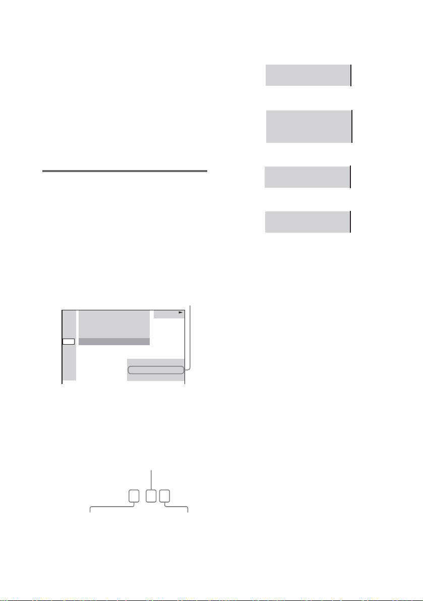
4 Press ENTER.
To turn off the Control Menu
Press DVD DISPLAY repeatedly until the
Control Menu is tur ned off.
Notes
• For discs not in multiple audio format, you cannot
change the sound.
• During DVD playback, the sound may change
automatically.
Tip
You can select [AUDIO] directly by pressing AUDIO.
Each time you press the button, the item changes.
The display examples are as
follows:
•PCM (stereo)
PROGRAM FORMAT
PCM 48kHz 24bit
• Dolby Surround
PROGRAM FORMAT
DOLBY DIGITAL 2/0
DOLBY SURROUND
• Dolby Digital 5.1ch
Displaying the audio
information of the disc
(DVD only)
When you select [AUDIO], the channels bei ng
played are displayed on the screen.
For example, in Dolby Digital format, multiple
signals ranging from monaural to 5.1 channel
signals can be recorded on a DVD. Depending
on the DVD, the number of recorded channels
may differ.
Current audio format*
1:DVD
1 2 ( 2 7 ) TITLE12
)
1 8 ( 3 4
T
1 : 3 2 : 5 5
1: ENGLISH
PROGRAM FORMAT
DOLBY DIGITAL 3/2.1
*[PCM], [MPEG], [DTS], or [DOLBY
DIGITAL] is displayed.
For [DOLBY DIGITA L ], the channels in the
playing track are displayed numerically as
follows:
For Dolby Digital 5.1 ch:
Surround component 2
DVD
PROGRAM FORMAT
DOLBY DIGITAL 3/2.1
•DTS
PROGRAM FORMAT
DTS 3/2.1
Tips
• Whe n the signal contains surround signal
components such as LS, RS, or S, the surround effect
is enhance d.
• If you play MPEG AUDIO sound tracks, the system
outputs PCM (stereo) signals.
• Even though the audio stream contains a surround
back component, the surround back channel is not
displayed.
Dolby Digital-EX or DTS-ES source is dis pla ye d as
“3/2.1”on the screen.
58
DOLBY DIGITAL
Front component 2 +
Center component 1
US
3 / 2 . 1
LFE (Low Frequency
Effect) component 1
Page 59

Enjoying Surround Sound
T
Automatic decoding of the
audio input signal (AUTO
FORMAT DIRECT AUTO)
You can take advant age of surround sound
simply by selecting one of system’s preprogrammed sound fields. They bring the
exciting and powerful sound of movie theaters
into your home.
To select sound field, press AUTO FORMAT
DIRECT or MODE on the remote repeatedly
until the sound field you want appears in the
front panel display.
Tip
When you want to output the TV sound or stereo sound
of a 2 channel sou rce from the 6 sp eakers of the system,
select a sound field other than “AUTO FORMAT
DIRECT AUTO” or “2 CHANNEL STEREO”.
The auto decoding function automatically
detects the type of audio signal being input
(Dolby Digital, DTS, or standard 2 channel
stereo) and perf or m s t he proper decoding if
necessary. This m ode presents the sound as it
was recorded/ encoded, without adding any
effects (e.g. reverberation).
However, if ther e ar e no low frequency si gn als
(Dolby Digital LFE, etc.), it will generate a low
frequency signal for output to the subwoofer.
AUTO FORMA
DIRECT
With cover opened.
Press AUTO FORMAT DIRECT repeatedly
until “A.F.D. AUTO” appears in the front
panel display.
Sound Adjustments
Sound field Display
AUTO FORMAT DIRECT
AUTO
A.F.D. AUTO
59
US
Page 60

Using only the front speake r
T
and subwoofer (2 CHANNEL
STEREO)
This mode outputs the sound from the fr ont left
and right speakers and subwoofer. Standard two
channel (stereo) s our ces completely bypass the
sound field process i ng. Multi channel surround
formats are downmi xed to two channels .
This allows you to play any source using only
the front left and right speakers and subwo ofer.
Selecting a sound field (AUTO
FORMAT DIRECT button)
AUTO FORMA
DIRECT
MODE
With cover opened.
Press MODE repeatedly until “2CH
STEREO” appears in the front panel
display.
Sound field Display
2 CHANNEL STEREO 2CH STEREO
With cover opened.
Press AUTO FORMAT DIRECT repeatedly
until the sound field you want appears in
the front panel display.
Sound field Display
AUTO FORMAT DIRECT
PRO LOGIC
AUTO FORMAT DIRECT
PRO LOGIC II MOVIE
AUTO FORMAT DIRECT
PRO LOGIC II MUSIC
Neo:6 CINEMA NEO:6 CIN
Neo:6 MUSIC NEO:6 MUS
x AUTO FORMAT DIRECT PRO LOGIC
DOLBY PL
PLII MOVIE
PLII MUSIC
Dolby Pro Logic produces five output channels
from two-channel sources. This mode performs
Pro Logic decoding to t he input signal and
output to front, cen te r, and surround speakers.
Meanwhile, the s urround channel becomes
monaural.
60
US
Page 61

x AUTO FORMAT DIRECT PRO LOGICII
MOVIE/MUSIC
Dolby Pro Log icII pr oduce s five fu ll-ban dwidth
output channels from two-channe l sources. This
is done using an advan ced, high-purity matrix
surround decoder that extracts the spatial
properties of the or ig inal recording without
adding any new sounds or tonal colorations.
x Neo:6 CINEMA
Performs the DTS Neo:6 Cinema mode
decoding.
x Neo:6 MUSIC
Performs the DTS Neo:6 Music mode decoding.
This setting is ideal for sta nda rd stereo sources,
such as CDs.
Notes
• When the input signal is a multi-channel source, PRO
LOGIC, PRO LOGIC II MOVIE/MUSIC, and Neo:6
Cinema/Music are cancelled and the multi chann el
source is output directly.
• Neo:6 Cinema/Music mode decoding is not available
for DTS 2channel signal.
• Thi s system is not compatible with the DTS 96/24
decoding function. When you play th e DTS 96/24
disc, the system plays it as a normal disc.
Selecting a sound field (MODE
button)
Sound Adjustments
MODE
With cover opened.
Press MODE repeatedly until the sound
field you want appears in the front panel
display.
For movie
Sound field Display
CINEMA STUDIO EX A C. ST. EX A*
CINEMA STUDIO EX B C. ST. EX B*
CINEMA STUDIO EX C C. ST. EX C*
*Use DCS Technology
About DCS (Digital Cinema Sound)
In collaboration with Sony Pictures
Entertainment, Sony measured the sound
environment of th ei r studios and integrated the
data of the measurement and Sony’s own DSP
(Digital Signa l Pr ocessor) technology to
develop “Digi tal Cinema Sou nd . ” “Digital
Cinema Sound” simulates in a home theater an
ideal movie theater sound envi ronment based on
the preference of the movie director.
x C. ST. EX A (C in ema Studio EX A)
Reproduces the sound characteristics of the
Sony Pictures Enter t ai nment “Cary Grant
Theater” cinema production studio. This is a
standard mode, great for watching most any type
of movie.
continued
61
US
Page 62

x C. ST. EX B (Cinema Studio EX B)
Reproduces th e sound characteri stics of the
Sony Pictures Entertainment “Kim Novak
Theater” cinema pr oduction studio. This mode
is ideal for watching science-fiction or action
movies with lots of sound effects.
x C. ST. EX C (Cinema Studio EX C)
Reproduces th e sound characteri stics of the
Sony Pictures Entertainment scoring stage. This
mode is ideal for watching musicals or classic
films where music is featured in the sou ndtrack.
About Cinema Studio EX
Cinema Studio EX is ideal for enjoying the
movie software encoded with multi channel
format, such as the Dol by Digital DVD. This
mode reproduces the sound characteristics of
Sony Pictures Entertainment’s studios.
Cinema Studio EX consists of the following
three elements .
• Virtual Multi Dimension
Creates 5 sets of v irtual speakers surrounding
the listener from a single pair of actual
surround speakers.
• Screen Depth Matching
In a movie theater, sound seem s to come f rom
inside the image reflected on the movie screen.
This element creates the same sensation in
your listening room by shifting the sound of
the front speakers “into” the screen.
• Cinema Studio Reverberation
Reproduces th e reverberations peculiar to a
movie theater. Cinema Studio EX is the
integrated mode which operates these
elements simultaneously.
Notes
• The virtual speaker effect may cause increased noise
in the playback signal.
• When listening with sound fields that employ virtual
speakers, you will not be able to hear any sound
coming directly from the surround speake r s.
For music or others
Sound field Display
HALL HALL
JAZZ CLUB JAZZ CLUB
LIVE CONCERT L. CONCERT
GAME GAME
SPORTS SPORTS
MONO MOVIE MONO MOVIE
x HALL (Hall)
Reproduces the acoustics of a rectangular
concert hall.
x JAZZ CLUB (Jazz club)
Reproduces the acoustics of a jazz club.
x L. CONCERT (Live concert)
Reproduces the acoustics of a 300-seat live
concert.
x GAME (Game)
Obtains maximum audio impact from video
game softwa re.
x SPORTS (Sports)
Simulates the arena or stadium sound.
x MONO MOVIE (Mono movie)
Reproduces mono sound that is good for old
movies.
When using headphones
Sound field Display
HEADPHONE 2CH HP 2CH
HEADPHONE THEATER HP THEATER
x HEADPHONE 2CH
This mode outputs the s ound from the
headphone L/R. St andard 2 channel (stereo)
sources completely bypass the sound field
processing. Multi channel surround format s are
downmixed to two channels.
x HEADPHONE THEATER
This mode outputs th e s ound as surround from
headphone L/R.
62
US
Page 63
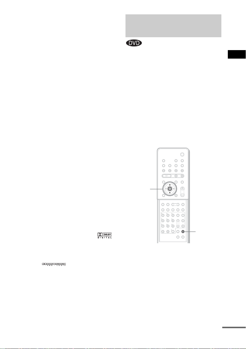
To turn the surround effect off
Press AUTO FORMAT DIRECT repeatedly
until “A.F.D. AUTO” appears i n the f ront p anel
display.
When connecting the headphones to the
PHONES jack
Press AUTO FORMAT DIRECT or MODE
repeatedly unti l “HP 2CH” appears in the fron t
panel display.
Notes
• Thi s func tion is unavailable when playing Super
Audio CDs and when the input stream is dts 2048
frame.
• When you play a Super Audio CD (Direct Stream
Digital), the sound field changes to “AUTO
FORMAT DIRECT AUTO” automatically.
• Thi s system is not compatible with the DTS 96/24
decoding function. When you play th e DTS 96/24
disc, the system plays it as a normal disc.
Tips
• When you wa nt to output the TV sound or stereo
sound of a 2 channel source from the 6 or 7 speakers,
select any sound field other than “AUTO FORMAT
DIRECT AUTO” or “2CH STEREO.”
• The system memorizes the last sound field selected
for each function mode.
Whenever you select a function such as DVD or
TUNER, the sound field that was last applied to
function is automatically applied again. For example,
if you listen to DVD with HALL as the sound field,
then change to another function, and then return to
DVD, HALL will be applied again. With the tuner,
sound fields are memorized se para te ly for all preset
stations.
• You can identify the encoding format of progra m
software by looking at its packaging.
– Dolby Digital discs are labeled with the
logo.
– DTS-ES encoded programs are marked with
DTS-ES.
– Dolby Surround encoded programs are labele d
with the logo.
– DTS Digital Surround discs are marked with DTS.
Selecting the Surround
Back Decoding Mode
This function lets you select the decoding mode
for the surround back signals of the multi
channel input stream.
By decoding the surround back signal of DVD
software, etc., recorded in Dolby Digital EX,
DTS-ES Matrix, DTS-ES Discrete 6.1 format,
etc., you can enjoy t he kind of surround sound
originally intended for the film (pages 100 and
101).
Note
This function works only when you conne ct the
surround back speaker to the system (page 18) and set
[SURROUND BACK] to [YES] in the [SIZE] setting
(page 87).
ENTER
X/x
AMP MENU
With cover opened.
1 Press AMP MENU.
2 Press X/x repeatedly until
“CUSTOMIZE” appears in the front
panel display, then press ENTER.
3 Press X/x repeatedly until “SB DEC”
appears in the front panel display, then
press ENTER.
Sound Adjustments
continued
63
US
Page 64

4 Press X/x to select the surround back
mode you want according to the input
stream, then press ENTER or AMP
MENU.
The default setting is “SB MATRIX.”
When selecting “SB MATRIX”
Dolby Digital EX or DTS-ES is applied to
decode the surr ound back signal regardless of
the 6.1 ch annel de code flaga) in the input stream.
This decoder conforms to Dolby Digital EX or
DTS-ES.
Input stream Outp ut
Dolby Digital
5.1
DTS 5.1 6.1 DTS Matrix decoder
Dolby Digital
b)
EX
DTS-ES Matrix
c)
6.1
DTS-ES
Discrete 6.1
channel
6.1 Matrix decoder conforms
6.1 Matrix decoder conforms
6.1 DTS Matrix decoder
6.1 DTS Discrete decoder
d)
When selecting “SB AUTO”
When you inp ut st ream cont ains the 6. 1 ch anne l
decoding flag
a)
, the appropriate decoder is
applied to decode the surround back signal .
Applied surr ound back
decoder
to Dolby Digital EX
to Dolby Digital EX
When selecting “SB OFF”
Surround back dec oding is not performed.
a) 6.1 channel decode flag is information recorded in
software like DVD.
b) Dolby Digital DVD that includes a Surround EX
flag. Check the Dolby Corporation web page help
for information about Sur ro und EX fi lm s.
c) Software encoded with a flag to denote it has both
Surround EX and 5.1 channel signals.
d) Software encoded with both 5.1 channel signals and
an extension stream designed for returning those
signals to 6.1 discrete channel s. Dis cre te 6.1
channel signals are DVD specific signals, not used
in movie theaters.
Notes
• You can select the surround back decoding only when
AUTO FORMAT DIRECT AUTO mode is selected
(page 59). In other sound fields, this function is
bypassed internally.
• Som e di sc s hav e no Dolby Digital EX flag, even
though their packaging may contain a Dolby Digital
Surround EX logo. In this case, select
MATRIX.
”
“SB
64
Input stream Outp ut
Dolby Digital
5.1
DTS 5.1 5.1 —
Dolby Digital
b)
EX
DTS-ES Matrix
c)
6.1
DTS-ES
Discrete 6.1
US
d)
channel
5.1 —
6.1 Matrix decoder conforms
6.1 DTS Matrix decoder
6.1 DTS Discrete decoder
Applied surr ound back
decoder
to Dolby Digital EX
Page 65

Using the Sound Effect
This system provides you with 2 types of sound
effect, simply by pressing a button. Choose the
sound to suit your needs.
Notes
• The NIGHT MODE function is activated only when
the input stream is Dolby D igital format.
• When you connect headphones to the system, the
DSGX function does not work.
• These two types of sound effect cannot be activated
at the same time.
• Depending on the input stream, the DSGX function
may not be effective.
Sound Adjustments
DSGX
With cover opened.
Press NIGHT MODE or DSGX on the
remote.
NIGHT
MODE
The sound effect i s activated.
x NIGHT MODE
In this mode, you can enjoy sound effects or
dialogue, as you would in a movie theater, even
at low volume. It is useful for watching movies
at night.
x DSGX
With DSGX on, bass freq uencie s are ef fectiv ely
reinforced.
To turn off the sound effect
Press NIGHT MODE or DSGX again.
65
US
Page 66

Using Various Additiona l Funct io ns
Changing the Angles
If various angles (multi-angles) for a scene are
recorded on a DVD, you can change the viewing
angle.
For example , w h i l e playing a s cene of a train in
motion, you can display the view from either the
front of the train, the left window of the train , or
from the righ t window with out having the train’s
movement interrupted.
DVD
DISPLAY
ANGLE
C/X/x/c/
ENTER
3 Press ENTER or c.
The angle number ch anges to “-.”
1:DVD
1 2 ( 2 7 ) TITLE12
)
1 8 ( 3 4
T
1 : 3 2 : 5 5
)
– ( 9
DVD
4 Select the angle number using the
number buttons or X/x, then press
ENTER.
The angle is changed to t he selected angle.
To turn off the Control Menu
Press DVD DISPLAY repeatedly until the
Control Menu is turned off.
Note
Depending on the DVD, you may not be able to change
the angles, even if multi- an g les are reco rd ed on the
DVD.
Tip
You can select the angle directly by pressing ANGLE.
Each time you press the button, the an gle changes.
66
With cover opened.
1 Press DVD DISPLAY during playback.
The Control Men u appears.
2 Press X/x to select (ANGLE).
The angle number a ppears.
The number in parentheses indicates the
total number of angle s. The [ANGLE]
indicator lights up in green when angles are
recorded on the disc .
1:DVD
1 2 ( 2 7 ) TITLE12
)
1 8 ( 3 4
T
1 : 3 2 : 5 5
)
1
( 9
US
Number
Buttons
DVD
Page 67
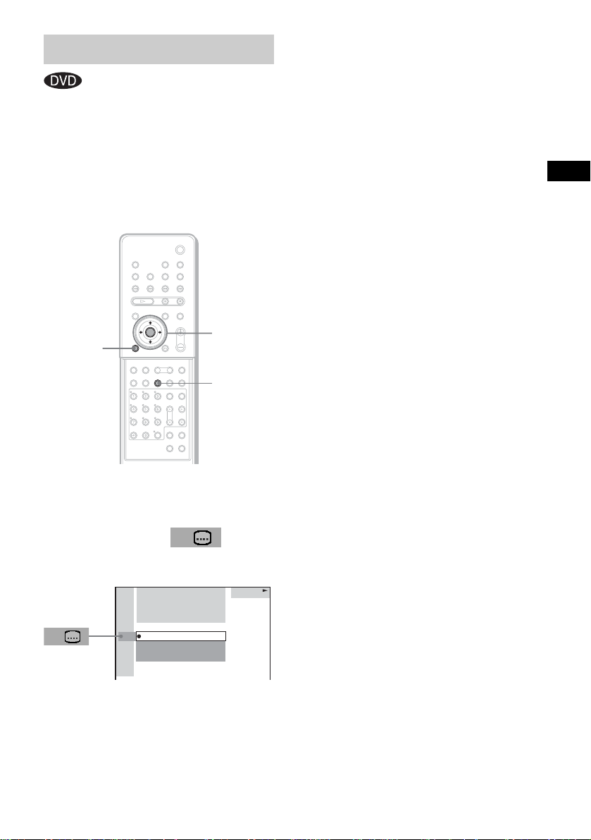
Displaying Subtitles
If subtitles are recorded on a disc, you can turn
the subtitles on or off while playing. If
multilingual su bt it l es are recorded on the disc,
you can change the su btitle language while
playing, or turn the subtitles on or off whenever
you want. Yo u can sele ct the langua ge you wa nt
to practice, for e xample, tu rn on the subtitl es for
better understandi ng.
DVD
DISPLAY
C/X/x/c/
ENTER
SUBTITLE
3 Press X/x to select the language.
Depending on the DVD, the choice of
language varies .
When 4 digits are displayed, they indicate
the language code. Refer to the language
code list on page 108 to see which language
the code repre sents.
4 Press ENTER.
To cancel the [SUBTITLE] setting
Select [OFF] in Step 3.
To turn off the Control Menu
Press DVD DISPLAY repeatedly until the
Control Menu is turned off.
Note
Depending on the DVD, you may not be able to change
the subtitles, even if mult ilingual subti tles are recorded
on it.
Tip
You can select subtitles directly by pressing
SUBTITLE. Each time you press the button, the
language changes.
Using Various Additional Functions
With cover opened.
1 Press DVD DISPLAY during playback.
The Control Menu ap pears.
2 Press X/x to select
(SUBTITLE), then press ENTER or c.
The options for [SUBTITLE] appear.
1:DVD
1 2 ( 2 7 ) TITLE12
)
1 8 ( 3 4
T
1 : 3 2 : 5 5
OFF
1: ENGLISH
2: FRENCH
3: SPANISH
DVD
US
67
Page 68

Locking Discs
(CUSTOM PARENTAL CONTROL,
PARENTAL CONTROL)
You can set two kinds of playback restriction s
for a disc.
• Custom Parental Control
You can set the playback restrictions so that
the system will not play inappropriate discs.
• Parental Cont r ol
Playback of some DVDs can be limited
according to a predetermined level, such as the
age of the viewer .
The same password is used for both Parental
Control and Cus t om Parental Control .
Custom Parental Control
You can set the sam e Custom Parental Control
password for up to 25 discs. If you set a 26th
disc, the playback restriction of the disc for
which yo u fi rst set the passw ord is cancelled.
3 Press X/x to select (CUSTOM
PARENTAL CONTROL), then press
ENTER or c.
[CUSTOM PARENTAL CONTROL] is
selected.
1:DVD
1 2 ( 2 7 ) TITLE12
)
1 8 ( 3 4
T
1 : 3 2 : 5 5
ON
PASSWORD
DVD
4 Press X/x to select [ON t], then press
ENTER.
x If you have not entered a password
yet
The display for registering a new password
appears.
CUSTOM PARENTAL CONTROL
Enter a new 4-digit password,
ENTER
then press .
68
C/X/x/c/
ENTER
DVD
DISPLAY
Number
buttons
With cover opened.
1 Insert the disc you want to lock.
If the disc is playing, press x to stop
playback.
2 In stop mode, press DVD DISPLAY.
The Control Men u appears.
US
x
O RETURN
Enter a 4-digit pass w or d by using the
number buttons, then pre ss EN TER.
The display for confirming the password
appears.
x If you have already registered a
password
The display for entering the password
appears.
CUSTOM PARENTAL CONTROL
Enter password, then press .
ENTER
Page 69

5 Enter your 4-digit password by using
the number buttons, then press
ENTER.
[Custom parental control is set.] appears
and the screen returns to the Cont ro l Men u
display.
If you make a mistake entering your
password
Press C before you press ENTER and input
the correct numb er.
If you make a mistake
Press O RETURN, then start from Step 3
again.
To turn off the Control Menu
Press DVD DISPLAY repeatedly until the
Control Menu is turned off.
To turn off the Custom Parental
Control function
1 In Step 4, select [OFF t], then press
ENTER.
2 Enter your 4-digit password using the
number buttons, then press ENTER.
To change the password
1 In Step 4, press X/x to select [PASSWORD
t], then press ENTER.
The display for entering the password
appears.
2 Enter your 4-digit password using the
number buttons, then press ENTER.
3 Enter a new 4-digit password using the
number buttons, then press ENTER.
4 To confirm your password, re-enter it using
the number buttons, then press ENTER.
Playing the disc for which
Custom Parental Control is
set
1 Insert the disc for which Custom
Parental Control is set.
The [CUSTOM PARENTAL CONTROL]
display appears.
CUSTOM PARENTAL CONTROL
Custom parental control is already
set. To play, enter your password
ENTER
and press .
2 Enter your 4-digit password using the
number buttons, then press ENTER.
The system is ready for pl ayback.
Notes
• When you change the layer or area in a Super Audio
CD which has Custom Parental Cont ro l se t, the
display for entering the password may appear.
• When you set the Custom Parental Control password
for a Hybrid Super Audio CD, the Custom Par e nta l
Control setting only works for the current layer.
Tip
If you forget your password, enter the 6-digit number
“199703” using the number buttons when the
[CUSTOM PARENTAL CONTROL] display asks
you for your password, then press ENTER. The display
will ask you to enter a new 4-digit password.
Using Various Additional Functions
69
US
Page 70

Limiting pla yback for c hildren
(Parental Control)
(DVD only)
Playback of some DVDs can be limited
according to a predetermined level, such as the
age of the viewer. The “Parental Control”
function allows you to set a p la yback limitation
level.
A scene that is limited is not played, or it is
replaced by a diffe rent scene.
C/X/x/c/
ENTER
DVD
SETUP
O RETURN
Number
buttons
3 Press X/x to select [PARENTAL
CONTROL t], then press ENTER or c.
x If you have not entered a password
The display for registering a new password
appears.
CUSTOM SETUP
PARENTAL CONTROL
Enter a new 4-digit password,
ENTER
then press
.
Enter a 4-digit pass w or d using the number
buttons, then press ENTE R.
The display for confirming the password
appears.
x When you have already registered a
password
The display for entering the password
appears.
CUSTOM SETUP
PARENTAL CONTROL
Enter password, then press
ENTER
.
70
With cover opened.
1 In stop mode, press DVD SETUP.
The Setup Display appears.
2 Press X/x to select [CUSTOM SETUP],
then press ENTER or c.
[CUSTOM SETUP] is displayed.
CUSTOM SETUP
PARENTAL CONTROL
US
4 Enter your password using the number
buttons, then press ENTER.
The display for set t ing the playback
limitation level and c hangin g th e p as sword
appears.
CUSTOM SETUP
PARENTAL CONTROL
LEVEL: OFF
OFFTRACK SELECTION
OFFAUDIO DRC:
MP3DATA CD PRIORITY:
MM/DD/YYYYJPEG DATE:
STANDARD:
CHANGE PASSWORD
USA
Page 71

5 Press X/x to select [STANDARD], then
press ENTER or c.
The selection items for [STANDARD] are
displayed.
CUSTOM SETUP
PARENTAL CONTROL
LEVEL:
STANDARD:
CHANGE PASSWORD
OTHERS
OFF
USA
6 Press X/x to select a geographic area
as the playback limitation level, then
press ENTER.
The area is selected.
If you select [O T H ERS t], select an d
enter the standard code in the table on
page 72 usin g th e number buttons.
7 Press X/x to select [LEVEL], then press
ENTER or c.
The selection items for [L EVEL ] are
displayed.
CUSTOM SETUP
PARENTAL CONTROL
STANDARD:
CHANGE PASSWORD
OFFLEVEL:
8:
NC17
7:
R
6:
5:
PG13
4:
PG
3:
2:
G
1:
If you make a mistake
Press O RETURN or C to go back to the
previous screen.
To turn off the Setup Display
Press DVD SETUP repeatedly until the Setup
Display is turned off.
To turn off the Parental Control
function and play the DVD after
entering your password
Set [LEVEL] to [OFF] in Step 8.
To change the password
1 In Step 5, select [CHANGE PASSWORD
t] using x, then press ENTER or c.
The display for entering the password
appears.
2 Follow Step 3 to enter a new password.
Using Various Additional Functions
8 Select the level you want using X/x,
then press ENTER.
The Parental Control setting is complete.
CUSTOM SETUP
PARENTAL CONTROL
STANDARD:
CHANGE PASSWORD
The lower the value, the more strict the
limitation.
PG134:LEVEL:
USA
71
US
Page 72

Playing the disc for which
Parental Control is set
1 Insert the disc and press H.
The [PARENTAL CONTROL] display
appears.
2 Enter your 4-digit password using the
number buttons, then press ENTER.
The system starts pl ayback.
Notes
• If you play a DVD which does not have the Parental
Control function, playback cannot be limited on this
system.
• Depending on the DVD, you may be asked to change
the Parental Control level while playing the disc. In
this case, enter your password, then change the level.
If the Resume Play mode is ca nc elled, the level
returns to the original le vel.
Tip
If you forget your password, remove the disc and
repeat Step 1 to 3 of “Limiting playback for children.”
When you are asked to enter your password, ent er
“199703” using the number buttons, then press
ENTER. The display will ask you to enter a new 4-digit
password. After you enter a new 4-digit password in
Step 3, replace the disc in the system and press H.
When the [PARENTAL CONTROL] display appears,
enter your new password.
Area Code
Standard Code number
Argentina 2044
Australia 2047
Austria 2046
Belgium 2057
Brazil 2070
Canada 2079
Chile 2090
China 2092
Denmark 2115
Finland 2165
France 2174
Germany 2109
Hong Kong 2219
India 2248
Indonesia 2238
Italy 2254
Japan 2276
Korea 2304
Malaysia 2363
Mexico 2362
Netherlands 2376
New Zealand 2390
Norway 2379
Pakistan 2427
Philippines 2424
Portugal 2436
Russia 2489
Singapore 2501
Spain 2149
Sweden 2499
Switzerland 2086
Taiwan 2543
Thailand 2528
United Kingdom 2184
72
US
Page 73

Other Operations
Controlling TV with the
Supplied Remote
By adjusting the remote signal, you can control
your TV with the supplied remote.
Notes
• If you enter a new code number, the code number
previously entered will be erased.
• Whe n you r e pla c e the ba tteries of the remote, the
code number may reset itself to the default (SONY)
setting. Reset the appropri at e code n umber.
Controlling TVs with the
remote
TV ?/1
TV/VIDEO
Number
buttons
With cover opened.
Press and hold TV [/1 while entering your
TV’s manufacturer’s code (see the table)
using the number buttons. Then release TV
[/1.
If you set successfully the manufacturer’s code,
the TV button flashes twice slowly. If the setting
is unsucces sful, the TV button flash es five times
quickly.
TV button
TV CH +/–
TV VOL +/–
Code numbers of controllable TVs
If more than one code number is listed, try
entering them one at a time until you find th e one
that works with your TV.
TV
Manufacturer Code number
SONY 001
Admiral 012, 016, 039
AKAI 002
AOC 002
Bell&Howell 016, 039
Broksonic 002
Croslex 034
CURTIS-MATHES 002, 046
DAEWOO 002, 004, 005, 006
Daytron 020
EMERSON 002, 020
FISHER 009
General Electric 002, 012, 049
HITACHI 002, 014, 015, 020
JC Penny 002, 012
JVC 018
KTV 002, 020
LG/Goldstar 002, 020
LXI(Sears) 002, 009, 012, 034, 046
MAGNAVOX 002, 020, 027, 034
MARANTZ 022
Mitsubishi/MGA 002, 022
NEC 002
PANASONIC 049, 050
Philco 002, 004, 015, 020, 034
PHILIPS 027, 034
PIONEER 029, 046, 049
Portland 002
QUASAR 039, 049
RADIO SHACK 002, 012, 022
RCA/PROSCAN 002, 012, 032, 033
SAMSUNG 002, 020, 028, 036
SANYO 009, 010
SCOTT 002
SHARP 020, 039, 040
Signature 016, 039, 040
SYLVANIA 002, 034
TOSHIBA 039, 046
continued
Other Operations
73
US
Page 74

Manufacturer Code number
Videch 002, 015
WARDS 002, 020
ZENITH 016, 017
CATV
Manufacturer Code number
SONY 101
HAMLIN/REGAL 123, 124, 125, 126, 127
OAK 128, 129, 130
PANASONIC 120, 121, 122
PIONEER 115, 116
SCIENTIFIC
ATLANTA
TOCOM 117, 118, 131
ZENITH 113, 114
110, 111, 112
Controlling the TV
You can contro l your TV using the but t ons
below.
By pressing You can
TV [/1 Turn the TV on or off.
TV/VIDEO Switch the TV’s input source
between the TV and other input
sources.
TV VOL +/– Adjust the TV volume.
TV CH +/– Select the TV channel .
Using the number buttons for
controlling the TV
When you set the remote to the TV mode, you
can use the number buttons for controlling the
TV.
Press the TV button.
The TV button turns red and the remote is set to
the TV mode . You can sel ect the TV ch annels by
using the number buttons.
>10 is for selecting the channel number greater
than 10.
To cancel the TV mode, pr es s the TV button
again.
Notes
• Depending on the TV, you may not be able to control
your TV or to use some of the buttons above.
• The TV button turns off when you do not operate the
remote for 10 seconds.
Tip
Depending on the TV manufacture, the following
method also works. Press >10, then the num be r . (Fo r
example, for channel 25, press >10, then 2 and 5.)
74
US
Page 75
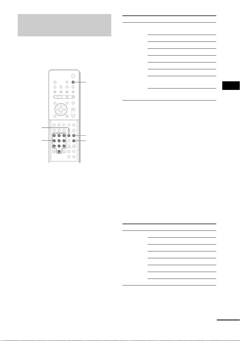
Using the SONY TV DIRECT
Function
SONY TV DIRECT allows you to turn on your
SONY TV and this system, change the system
mode to “DVD,” and then switch the TV’s input
source you set with one button push.
SONY TV
DIRECT
TV/VIDEO
Number
buttons
With cover opened.
Preparation
Register the TV’s input source connected to this
system.
Press and hold TV/VIDEO while entering
the code for the TV’s input so ur c e to
connect this system (see table below)
using the number button s .
TV’s inpu t source is selected.
If you successfully set the TV’s in put source
code, the TV button flashes twice slowly. I f th e
setting is unsucc essful, the TV button flashe s
five times quickly.
TV button
TV CH +
By pressing Number TV’s input source
TV/VIDEO 0 No input source
(Default)
1VIDEO1
2VIDEO2
3VIDEO3
4VIDEO4
5VIDEO5
6VIDEO6
7* COMPONENT1
INPUT
8* COMPONENT2
INPUT
* Except for North American models.
Operation
Point the remot e to t he direc tion of T V an d this
system, then press SONY TV DIRECT once.
While transmitting the code from the remote , the
TV button flas hes.
If this function does not work, change the
transmit time. The transmit time varies
depending on the TV.
To change the transmit time
Press and hold TV CH + while entering the
code for transmit time (see table below) using
the number buttons.
The transmit time from the remote is selected.
If you successfully set the transmit time code,
the TV button flashes twice slowly . If the setting
is unsuccessful, the TV button flashes five times
quickly.
By pressing Number Transmit time
TV CH+ 1 0.5 (Default)
21
31.5
42
52.5
63
73.5
84
Other Operations
continued
75
US
Page 76

Notes
• This function is only for SONY TV series.
• If distance between TV and this system is too far, this
function may not work . Install the system near the
TV.
• Keep the remote pointed in the direction of the TV
and this system while the TV b ut t on is flashing.
Using the Video or Other
Units
You can use VCRs or ot her units connected to
the VIDEO or SAT j acks. Refe r to the op erati on
manual supp li ed with the unit for fu rther
information on the operation.
FUNCTION
Press FUNCTION repeatedly until VIDEO or
SAT that you connected the unit to appears
in the front panel display.
Each time you press FUNCTION, the mode of
the system changes in the following sequence.
FM t AM t VIDEO t SAT t DVD t
FM...
76
US
Page 77

Enjoying Multiplex
Broadcast Sound
(DUAL MONO)
You can enjoy multiplex broadcast sound when
the system receive the AC-3 multiplex broadcast
signal.
Note
To receive the AC-3 signal, you need to connect a
digital satellite tuner to the system with an OPTICAL
cable (page 24) and set the digita l output mode of the
digital satellite tuner to A A C .
C/X/x/c/
ENTER
x SUB
Sub sound is output from the left and right
speakers.
x MAIN+SUB
Main sound and Sub sound are output from
the left and right speakers.
x MAIN/SUB
Main sound is outp ut from the left speaker
and Sub sound is out put from the right
speaker.
5 Press AMP MENU.
Turns off the AMP menu.
Other Operations
AMP MENU
With cover opened.
1 Press AMP MENU.
2 Press x/X repeatedly until
“CUSTOMIZE” appears in the front
panel display, then press ENTER or c.
The system enters th e C ustomize Menu
mode.
3 Press x/X repeatedly until “DUAL
MONO” appears in the front panel
display, then press ENTER or c.
4 Press x/X to select the sound you
want.
x MAIN
Main sound is output from the left and right
speakers.
77
US
Page 78

Enjoying the Radio
Presetting Radio Stations
You can preset 20 F M sta t io ns, and 10 AM
stations. Before tuning, make sure to turn down
the volume to minimum.
"/1
TUNER/
BAND
C/X/x/c/
ENTER
With cover opened.
TUNING –/+
TUNER
MENU
1 Press TUNER/BAND repeatedly until
the band you want appears in the front
panel display.
Each time you press TUNER/BAND, the
band toggles between AM and FM.
2 Press and hold TUNING + or – until
scanning starts, then release.
Scanning stops when the system tunes in a
station. “TUNED” and “ST” (for stereo
program) appear in the front panel display.
ST
MHz
5 Press ENTER.
A preset number appears in the front panel
display.
ST
6 Press C/c/x/X to select/ the preset
number you want.
ST
7 Press ENTER.
The station is stored.
m
ST
MHz
8 Repeat 1 to 7 to store other stations.
To change the preset number
Restart from st ep 1.
To change the AM tuning interval
The AM tuning interval can be set to either
10 kHz (default) or 9kHz (for some areas).
To change the AM tu ni ng interval, first tune in
any AM station, t hen turn off the system by
pressing "/1 on the remote, or "/1 on the
system. While holding down VOLUME + on the
system, press "/1 on the system to turn on the
power. If you chan ge the interval, AM preset
stations will be erased.
To reset the interval, repeat th e s ame pr ocedu re .
78
3 Press TUNER MENU.
4 Press C/c/x/X repeatedly until
“MEMORY ?” appears in the front
panel display.
US
Page 79

Listening to t he Radio
Preset radio stations in the system’s memory
first (see “Presetting Radio Stations” on
page 78).
TUNER/
BAND
DISPLAY
PRESET
–/+
With cover opened.
"/1
FUNCTION
TUNING –/+
x
VOL +/–
FM MODE
1 Press FUNCTION repeatedly until “FM”
or “AM” appears in the front panel
display.
The last received station is tuned in.
To listen to non-preset radio
stations
Use manual or automatic tuning in Step 2.
For manual tuni ng, pres s TUNIN G + or – on the
remote repeatedly.
For automatic tuning, press and h old TUNING +
or – on the remote. Press x when you stop the
automatic tuning.
Tips
• If an FM program is noisy, press FM MODE on the
remote so that “MONO” appears in the front panel
display. There will be no stereo effect , but the
reception will improve. Press the button again to
restore the stereo effect.
• To improve reception, reorient the supplied antennas
(aerials).
To check the frequency or sound
field
Press DISPLAY repeatedly.
Each time you press DISPLAY, the front panel
display changes as follows:
index name of the st ation* t frequency t
sound field t index name of the stati on...
*This is displayed if you have entered a name
for a preset stati on (page 80).
Other Operations
ST
MHz
2 Press PRESET + or – repeatedly to
select the preset station you want.
Each time you press the button, the system
tunes in one preset stat ion.
Each time you press TUNER/BAND, the
band toggles betwee n A M and FM.
3 Adjust the volume by pressing
VOL +/–.
To turn off the radio
Press "/1.
79
US
Page 80

Naming Preset Stations
You can enter a nam e of up to 8 characters for
preset stations. These names (for example,
“XYZ”) appear in the system’s front panel
display when a station is selected.
Note that no more than one n ame can be entered
for each preset st at i on.
TUNER/
BAND
PRESET
–/+
C/X/x/c/
ENTER
With cover opened.
FUNCTION
TUNER
MENU
1 Press FUNCTION repeatedly until “FM”
or “AM” appears in the front panel
display.
Each time you press TUNER/BAND, the
band toggles between AM and FM.
The last station you received is tuned in.
Each time you press FUNCTION, the mode
of the system changes in the following
sequence:
FM t AM t VIDEO t SAT t DVD
t FM...
2 Press PRESET+ or – repeatedly to
select the preset station you want to
create an index name for.
3 Press TUNER MENU.
6 Create an index name by using the
cursor buttons:
Press X/x to select a ch aracter, t hen press c
to move the cursor to the next position.
If you make a mistake
Press C/c repeatedly until the character to
be changed flashes, then press X/x to select
the desired character. Capital letters,
numbers, and other sym bols can be input
for a radio statio n name.
7 Press ENTER.
The station name is stored.
80
4 Press C/c repeatedly until “NAME IN?”
appears in the front panel display.
5 Press ENTER.
US
Page 81

Using the Sleep Timer
N
Changing the Brightness
You can set the sys tem t o turn off at a preset
time, so you can fall asleep listening to music.
You can preset the time in 10 minutes
decrements.
SLEEP
Press SLEEP.
Each time you press this button, the minutes
display (the remaining time) changes as follows:
AUTO t 90MIN t 80MIN t 70MIN
R
SLEEP OFF T 10MIN ..... 50MIN T 60MI
When you choose AUTO
The system turns o ff w hen the current disc
finishes playback ( up t o 240 minutes). The
system turns off if you manually stop playing a
disc.
“AUTO” mode works only with functions such
as DVD that is selected before setting to
“AUTO.”
To check the remaining time
Press SLEEP once. Yo u cannot check the
remaining time if you select “AUTO.”
To change the remaining time
Press SLEEP repeatedly to select the desired
time.
To cancel the Sleep Timer
function
Press SLEEP repeate dl y until “SLEEP OFF”
appears in the front panel display.
r
of the Front Panel Display
You can change the brightness of the front panel
display by two steps.
Other Operations
C/X/x/c/
ENTER
AMP MENU
With cover opened.
1 Press AMP MENU.
2 Press x/X repeatedly until
“CUSTOMIZE” appears in the front
panel display, then press ENTER or c.
The system enters the Customize Menu
mode.
3 Press x/X repeatedly until “DIMMER”
appears in the front panel display, then
press ENTER or c.
4 Press x/X to select the brightness of
the front panel display.
5 Press AMP MENU.
Turns off the AMP menu.
US
81
Page 82

Returning to the Default
Settings
You can return the system parameters such as
speaker settings and preset stations, to the
default settings.
DISC1 Z
Press ., , or DISC1 Z on the system at the
same time.
“COLD RESET” ap pears in the front panel
display and the default settings are retur ne d .
.
82
US
Page 83

Settings and Adjustments
Using the Setup Display
2 Press X/x to select the setup item from
the displayed list: [LANGUAGE
SETUP], [SCREEN SETUP], [CUSTOM
SETUP], [SPEAKER SETUP], and
[SETUP]. Then press ENTER or c.
The selected Setup item appears.
Example: [SCREEN SETUP]
By using the Setup Display, you can make
various adjustments to items, such as picture and
sound. You can also set the subtitle language
and the Setup Displa y, among other things. For
details on each Setup Display item, see page 84-
90. For an overall lis t of Setup Display items,
see page 109.
How to use the Setup Display
C/X/x/c/
ENTER
DVD
SETUP
With cover opened.
O RETURN
1 In stop mode, press DVD SETUP.
The Setup Disp l ay appears.
SCREEN SETUP
SCREEN SAVER:
BACKGROUND:
COMPONENT OUT:
4:3 LETTER BOXTV TYPE:
JACKET PICTURE
INTERLACE
ON
3 Select an item using X/x, then press
ENTER or c.
The options for the selected item appear.
Example: [TV TYPE]
SCREEN SETUP
TV TYPE:
SCREEN SAVER:
BACKGROUND:
COMPONENT OUT:
4:3 LETTER BOX
4:3 PAN SCAN
16:9
Options
Press C or O RETURN to return to setup
items.
4 Select a setting using X/x, then press
ENTER.
The setting is select ed and setup is
complete.
Example: [4:3 PAN SCAN]
Selected setting
Settings and Adjustments
Main
item
LANGUAGE SETUP
OSD :
DVD MENU :
AUDIO :
SUBTITLE :
ENGLISH
ENGLISH
ENGLISH
ENGLISH
SCREEN SETUP
TV TYPE: 4:3 PAN SCAN
SCREEN SAVER:
BACKGROUND:
COMPONENT OUT:
JACKET PICTURE
ON
INTERLACE
To turn off the Setup Display
Press DVD SETUP repeatedly until the Setup
Display is turned off.
83
US
Page 84

Setting the Display or
Settings for the Display
Sound Track Language
(LANGUAGE SETUP)
[LANGUAGE SETUP] allows you to set
various languages for the on-screen display or
sound track.
Select [LANGUAGE SETUP] in the Setup
Display. For details on using the display, se e
“Using the Setup D i splay” (page 83).
LANGUAGE SETUP
OSD :
DVD MENU :
AUDIO :
SUBTITLE :
x OSD (On-Screen Display)
Selects the display l anguage on the screen.
Select the language from the displayed list.
x DVD MENU (DVD only)
Selects the desired language fo r the DVD menu.
Select the language from the displayed list.
x AUDIO (DVD only)
Selects the langua ge of the sound track.
Select the language from the displayed list.
x SUBTITLE (DVD only)
Selects the language of the subtitle.
Select the language from the displayed list.
Note
If you select a language that is not rec or de d on the
DVD, one of the recorded languages will be
automaticall y selected (except for [OSD ]).
Tip
If you select [OTHERS t] in [DVD MENU],
[AUDIO], or [SUBTITLE], select and enter the
language code from the list using the number buttons
(page 108).
After you have made a selection, the language code (4
digits) is displayed the next time you select [OTHERS
t].
ENGLISH
ENGLISH
ENGLISH
ENGLISH
(SCREEN SETUP)
Choose settings according to the TV to be
connected.
Select [SCREEN SETUP] in the Setup Display.
For details on using the display, see “Using the
Setup Display” (pa ge 83).
The default settings are underlined.
SCREEN SETUP
TV TYPE: 4:3 LETTER BOX
SCREEN SAVER:
BACKGROUND:
COMPONENT OUT:
JACKET PICTURE
ON
INTERLACE
x TV TYPE (DVD only)
Selects the as pect rati o of the connec ted TV (4:3
standard or wide).
4:3
LETTER
BOX
4:3
PAN SCAN
16:9
Select this if you connect a 4:3
screen TV. Displays a wide picture
with bands on the upper and lower
portions of the screen.
Select this if you connect a 4:3
screen TV. Automatically displays
the wide picture on the entire
screen and cuts off the portions
that do not fit.
Select this if you connect a widescreen TV or a TV with a wide
mode function.
84
US
Page 85

4:3 LETTER BOX
4:3 PAN SCAN
16:9
Note
Depending on the DVD, [4:3 LETTER BOX] may be
selected automatically instead of [4:3 PAN SCAN] or
vice versa.
x SCR E EN SAVER
Turns the screen saver on and off so that the
screen saver image appears when you leave the
system in pause or stop mode for 15 minutes, or
when you playback a CD, a Super Audio CD, an
MP3, or JPEG fil e (except during the slide
show) for more than 15 minutes. The screen
saver will help prevent your display device from
becoming damage d ( afterimage). Press H to
turn off the screen saver.
ON
OFF
Turns on the screen saver.
Turns off the screen saver.
x BACKGROUND
Selects the background color or picture on the
TV screen in stop mode or while playing a CD.
JACKET
PICTURE
GRAPHICS 1-5
BLUE
BLACK
The jacket picture (sti l l p ict u re)
appears in the background, but
only if a jacket picture is already
recorded on the disc (CDEXTRA, etc.). If the disc does not
contain a jacket picture, the
[GRAPHICS 1] picture appears.
A preset picture stored in the
system appears in the background.
The background color is blue.
The background color is black.
x COMPONENT OUT
This will change t he type of signal output from
the COMPONENT VIDEO OUT jacks on the
system. See page 101 for more information
about the different types.
INTERLACE
PROGRESSIVE
Select this when you c o nn ect to a
standard (interlace format) TV.
Select this when you have a TV
that can accept progressive
signals.
To set to [PROGRESSIVE]
1 Select [COMPONENT OUT] in [SCREEN
SETUP] using X/x, then press ENTER.
SCREEN SETUP
TV TYPE:
SCREEN SAVER:
BACKGROUND:
COMPONENT OUT:
4:3 LETTER BOX
JACKET PICTURE
INTERLACE
PROGRESSIVE
ON
2 Select [PROGRESSI VE] using X/x, then
press ENTER.
The display for confi r m i ng appears.
SCREEN SETUP
TV TYPE:
SCREEN SAVER:
BACKGROUND:
COMPONENT OUT:
Does your TV accept progressive
signals?
YES
NO
4:3 LETTER BOX
JACKET PICTURE
ON
3 Select [YES] using X/x, then press ENTER.
The type of output signal changes to
progressive format.
Settings and Adjustments
continued
85
US
Page 86

Notes
• If your TV acc ep ts progr e ssive signals, connect
COMPONENT VIDEO OUT of the system to the TV
using a component video cord (not supplied), and set
progressive format.
• When [PROGRESSIVE] is se lected in [SCREEN
SETUP], no signal is ou tput from the MONITOR
OUT jacks.
• If you set [ COM PONENT OUT] in [ SCR EEN
SETUP] to [PROGRESSIVE] even though your TV
cannot accept the signal in progres sive format,
picture noise may appears. In this case, return the
setting to interlace format (page 25).
• The display for confirming does not appears when
you select [INTERLACE].
Custom Settings
(CUSTOM SETUP)
Allows setting up Parental Control and other
settings.
Select [CUSTOM SETUP] in the Setup Display.
For details on using the display, see “Using the
Setup Display” (pa ge 83).
The default settings are underlined.
CUSTOM SETUP
PARENTAL CONTROL
TRACK SELECTION
AUDIO DRC:
DATA CD PRIORITY:
x PARENTAL CONTROL t (DVD only)
Sets a password and playback limitation level
for DVDs with playback limitation for chil dren.
For details, see “Limiting playback for child re n
(Parental Control) (DVD only)” (page 70).
x TRACK SELECTION (DVD only)
Gives the sound track having the highest number
of channels pri ority when you play a DVD on
which multiple audio formats (PCM, MPEG
audio, DTS, or Dol b y Digital format) are
recorded.
OFF
OFF
MP3
MM/DD/YYYYJPEG DATE:
86
OFF
AUTO
Notes
No priority given.
Priority given.
• When you set the item to [AUTO], the language may
change. The [TRACK SELECTION] setting has
higher priority than the [AUDIO] settings in
[LANGUAGE SETUP] (page 84).
• If PCM, DTS, MPEG audio, and Dolby Digital sound
tracks have the s ame n umber o f cha nnels , th e sy stem
selects PCM, DTS, Dolby Digital, and MPEG audio
sound tracks in this order.
• Depending on the DVD, the audio channel with
priority may be predetermined. In this ca se , you
cannot give priority to the DTS, Dolby Digital, or
MPEG audio format by selecting [AUTO].
US
Page 87

x AUDIO DRC*
Narrows the DYNAMIC range of the sound
track.
Useful for watching movies at low volume late
at night.
* D y namic Range Compression
OFF
ON
Note
AUDIO DRC only applies to Dolby Digital sources.
No compression of DYNAMIC
range.
Reproduces the sound track with
the kind of DYNAMIC range that
the recording engineer intended.
x DA TA CD PRIORITY (MP3, JPEG only )
Set priority data you want to play, when you
play a DATA CD (CD-ROM/CD-R/CD-RW)
containing MP3 au di o t ra cks and JPEG image
files.
MP3
JPEG
If an MP3 file exists on a disc, the
system recognises the disc as an
“MP3 Disc.” If only JPEG files
exist on the disc, the system
recognises the disc as a “JPEG
Disc.”
If a JPEG file exists on the disc,
the system recogni ses the dis c as a
“JPEG Disc.” If only MP3 files
exist on the disc, the system
recognises the disc as an “MP3
Disc.”
x JPEG D AT E
Change the date information order of a JPEG
image in the Cont ro l Menu.
Settings for the Speakers
(SPEAKER SETUP)
To obtain the best possible surround sound, set
for the size of the speakers you have connected
and their distance from your listening position.
Then use the test tone to ad just the l evel and the
balance of the speakers to the same level.
Select [SPEAKER SETUP] in the Setup
Display. For details, see “Using the Setup
Display” (page 83).
The default sett i ngs are underlined.
SPEAKER SETUP
SIZE:
DISTANCE:
LEVEL:
BALANCE:
TEST TONE:
To return to the default setting
when changing a setting
Select the item, then press CLEAR.
x SIZE
If you do not connect center or surround
speakers, or move the surround speakers, set the
parameters for [CENTER] and [SURROUND]
and specify the surround speaker po sition and
height. Since the front speaker and subwoofer
settings are fixe d, you cannot change them.
If you connect the sur round back speaker, set
[SURROUND BACK] to [YES].
Settings and Adjustments
MM/DD/YYYY
YYYY/MM/DD
DD/MM/YYYY
YYYY/DD/MM
YYYY: Year
MM: Month
DD: Day
Position diagram
90
AA
45
BB
20
continued
US
87
Page 88

FRONT
CENTER
YES
YES: Normally select th is.
NONE: Select this if no center
speaker is used.
SURROUND
BEHIND: Select this if surround
speakers are located in section B.
SIDE: Select this if sur r ound
speakers are located in section A.
NONE: Select this if no surround
speaker is used.
SURROUND
BACK
(appears exce pt
when you set
[SURROUND]
to [NONE] in the
[SIZE] setting.)
SUBWOOFER
Notes
NONE: Normally select this.
YES: Select this if the surround back
speaker is used.
YES
• When you select an item, the sound cu ts o f f for a
moment.
• Depending on the settings of other speakers,
subwoofer may be excessive.
x DISTANCE
The default distance setting for the speakers in
relation to the listening po sition is s hown below.
When you set the di stance using the Quick Set up
(page 33), the settings is automatically
displayed.
1.6m
(5 FT)
1.6m
(5 FT)
1.6m
(5 FT)
Be sure to change the value in the Setup Display
when you move the speakers.
FRONT
1.6 m/5 ft
CENTER
1.6 m/5 ft
(appears when
you set
[CENTER] to
[YES] in the
[SIZE] setting.)
SURROUND
1.6 m/5 ft
(appears except
when you set
[SURROUND]
to [NONE] in
the [SIZE]
setting.)
SURROUND
BACK
1.6 m/5 ft
(appears when
you set
[SURROUD
BACK] to
[YES] in the
[SIZE] setting.)
* When you perform the Quick Setup (page 33), the
default settings are changed.
Notes
• Whe n you set the distance, the sound cuts off for a
moment.
• If all front and surround speakers are not placed at an
equal distance from your listening position, set the
distance according to the cl oses t speaker.
• Do not place the surround speakers farther away from
your listening position than the front speakers.
• Depending on the input stream, the [DISTANCE]
setting may not be effective.
Front speaker distance from the
*
listening position can be set in 0.2
meter (1 ft) increments from 1.0 to 7.0
meters (3 to 23 ft).
Center speaker distance can be moved
*
up to 1.6 meters (5 ft) closer to the
listening position from the front
speaker distance, in 0.2 meter (1 ft)
increments.
Surround speaker distance can be
*
moved up to 4.6 meters (15 ft) closer
to the listening position from the front
speaker distance, in 0.2 meter (1 ft)
increments.
Surround back speaker distance can
be moved up to 4.6 meters (15 ft)
closer to the listening p osition from
the front speaker distance, in 0.2 meter
(1 ft) incr ements.
88
1.6m
(5 FT)
US
1.6m
(5 FT)
1.6m
(5 FT)
Page 89

x LEVEL
You can vary the level of each speaker as
follows. Be sure to set [TEST T ONE] to [ON]
for easy adjustment.
x BALANCE
You can vary the balance of the left and right
speakers as follows. Be sure to set [TEST
TONE] to [ON] for easy adjustment.
CENTER
0 dB
*
(appears when
you set
[CENTER] to
[YES] in th e
[SIZE] setting.)
SURROUND
LEFT 0 dB
SURROUND
RIGHT 0 dB
(appears except
when you set
[SURROUND] to
[NONE] in the
[SIZE] setting.)
SURROUND
BACK
0 dB
(appears when
you set
[SURROUD
BACK] to [YES]
in the [S IZE]
setting.)
SUBWOOFER
*
+4 dB
Adjusts the level of the c e n te r
speaker (–6 dB to +6 dB, 1 dB
increments).
Adjusts the level of the surround
*
speakers (–6 dB to +6 dB, 1 dB
increments).
*
Adjusts the level of the surround
back speaker (–10 dB to +10 dB,
1 dB increments).
Adjusts the level of the subwoofer
(–6 dB to +6 dB, 1 dB increments).
* When you perform the Quick Setup (page 33), the
default settings are changed.
FRONT
(CENTER)
Adjusts the balance betw e en the front
left and right speakers.
The center position is shown as
“---.” (You can adjust from the center 6
steps to left or right.)
To adjust the volume of all the
speakers at one time
Use the VOLUME control on the system, or
press VOL +/–.
x TEST TONE
The speakers will emit a test tone to adjust
[LEVEL] and [BALANCE].
OFF
ON
The test tone is not emitted from the
speakers.
The test tone is emitted from both left and
right speakers simultaneously while
adjusting balance. When you select one of
the [SPEAKER SETUP] items, the test
tone is emitted from eac h speaker in
sequence.
Settings and Adjustments
89
US
Page 90

Adjusting the speaker
balance and leve l by using the
test tone
1 Press DVD SETUP in stop mode.
The Setup Display appears.
2 Press X/x repeatedly to select
[SPEAKER SETUP], then press ENTER
or c.
3 Press X/x repeatedly to select [TEST
TONE], then press ENTER or c.
4 Press X/x repeatedly to select [ON],
then press ENTER.
You will hear the te st tone from each
speaker in sequ ence.
5 From your listening position, adjust the
value of [BALANCE] and [LEVEL] using
C/X/x/c.
When selecting [BALANCE], the test tone
is emitted from both left and right sp eakers
simultaneously.
When selecting [LEVEL], the test tone is
emitted from only the speaker which you
are adjusting .
6 Press ENTER when you have finished
making adjustments.
7 Press X/x repeatedly to select [TEST
TONE], then press ENTER.
8 Press X/x repeatedly to select [OFF],
then press ENTER.
Notes
• When you adjust the speaker settings, the sound cuts
off for a moment.
• The surround back speaker level can be also adjus ted
on the amplifier that is connected to the surround
back speaker.
Tip
To adjust the balance or the le vel without listening to
the test tone, select [BALANCE] or [LEVEL] in step 3
and press ENTER. Then adjust the bala nc e or le ve l
using X/x and press ENTER.
Setting the spea kers by usi ng
the front panel display on the
system
You can set the spea kers by using the AMP
menu that is displayed in the front panel display.
AMP menu list
SP SETUP
CENTER SP
SURR SP
SURR B SP
F DIST
CEN DIST
SURR DIST
SB DIST
SP POS
LEVEL
TESTTONE
F BALANCE
CEN LEVEL
SL LEVEL
SR LEVEL
SB LEVEL
SW LEVEL
AUDIO DRC
a)
This setting appear s w h en you set “SURR SP”
to “SURR Y” in “SP SETUP.”
b)
This setting appears when you set the
corresponding speaker to “Y” in “SP SETUP.”
CENTER Y
CENTER N
SURR Y
SURR N
a)
SURR B N
SURR B Y
1.0 m - 7.0 m/3 ft to 23 ft
b)
1.0 m - 7.0 m/3 ft to 23 ft
b)
1.0 m - 7.0 m/3 ft to 23 ft
b)
1.0 m - 7.0 m/3 ft to 23 ft
b)
SP BEHIND
SP SIDE
T.TONE OFF
T.TONE ON
6 steps left or right
b)
–6 dB - +6 dB
b)
–6 dB - +6 dB
b)
–6 dB - +6 dB
b)
–10 dB - +10 dB
–6 dB - +6 dB
DRC OFF
DRC ON
90
US
Page 91

CUSTOMIZE
DUAL MONO
SL SR REVa)OFF
SB DEC
DIMMER DIM OFF
a)
This setting appears when you set “SURR
SP” to “SURR Y” in “SP SETUP.”
b)
This setting appears when you set “SURR
SP” to “SURR Y” and “SURR B SP” to
“SURR B Y” in “SP SETUP.”
C/X/x/c/
ENTER
MAIN
SUB
MAIN+SUB
MAIN/SUB
ON
b)
SB MATRIX
SB AUTO
SB OFF
DIM ON
With cover opened.
AMP MENU
1 Press AMP MENU.
2 Press X/x repeatedly until the item you
want to set appears in the front panel
display.
xSP SETUP
Sets the speaker si ze, distance, and place.
xLEVEL
Sets the balance and level of the each
speaker, and turns on/off the test t on e.
3 Press ENTER or c.
4 Press X/x to select the desired item,
then press ENTER or c.
To set the item, press X/x, then press
ENTER or AMP MENU.
You can set the following items. The
default settings are underlined.
xSP SETUP
CENTER SP
(center
speaker)
SURR SP
(surround
speakers)
SURR B SP
(surround
back
speaker)
F DIST
(front
distance)
1.6m/5 ft
CEN DIST
(center
distance)
1.6m/5 ft
SURR DIST
(surround
distance)
1.6m/5 ft
SB DIST
(surround
back
distance)
1.6m/5 ft
SP POSc)
(surround
speakers
position)
a)
This setting appears when you set “SURR S P”
to “SURR Y” in “SP SETUP.”
CENTER Y: Select this if you
use a center speaker.
CENTER N: Select this if no
center speaker is used.
SURR Y: Select this if you
use surround speakers.
SURR N: Select th is if no
surround speaker is used.
a)
SURR B N: Select this if no
surround back speaker is
used.
SURR B Y: Select this if you
use a surround back speaker.
Front speaker distance from
the listening position can be
set in 0.2 meter (1 ft)
b)
increments from 1.0 to 7.0
meters (3 to 23 ft).
c)
Center sp eaker distance ca n
be moved up to 1.6 meters (5
ft) closer to the listening
b)
position from the front
speaker distance, in 0.2 meter
(1 ft) increments.
c)
Surround speaker distance
can be mo ved up t o 4.6 me ters
(15 ft) closer to the listening
b)
position from the front
speaker distance, in 0.2 meter
(1 ft) increments.
c)
Surround back speaker
distance can be moved up to
4.6 meters (15 ft) closer to the
listening position from the
b)
front speaker distance, in 0.2
meter (1 ft) increments.
SP BEHIND: Select this if
surround speakers are loc ated
in the back area of the
listening position.
SP SIDE: Select this if
surround speakers are loc ated
in the side area of the listening
position.
Settings and Adjustments
continued
91
US
Page 92

b)
When you perform the Quick Setup (page 33),
the default settings are change d.
c)
This setting appears when you set the
corresponding speaker to “Y” in “SP SETUP”
(page 91 ).
xLEVEL
TEST TONE
(test tone)
T. TONE OFF: The test tone is
not emitted from the speakers.
T. TONE ON: The test tone is
emitted from both left and
right speakers simultaneously
while adjusting bala nce. When
you select one of the
“LEVEL” item s, the test tone
is emitted from each speaker in
sequence.
F BALANCE
(front
balance)
0
Adjusts the balance betw e en
the front left and right
speakers. (You can adjust from
the center 6 steps left (L6) or
right (R6).)
CEN LEVEL
(center level)
a)
0
SL LEVEL
(surround
left level)
a)
0
SR LEVEL
(surround
right level)
a)
0
SB LEVEL
(surround
back level)
a)
0
SW LEVEL
(subwoofer
level)
a)
+4
AUDIO DRC
(dynamic
compression)
b)
Adjusts the level of the ce nte r
speaker (–6 dB to +6 dB, 1 dB
increments).
b)
Adjusts the left leve l of the
surround speaker (–6 dB to +6
dB, 1 dB increments).
b)
Adjusts the right level of the
surround speaker (–6 dB to +6
dB, 1 dB increments).
b)
Adjusts the level of the
surround back speaker (–10
dB to +10 dB, 1 dB
increments).
Adjusts the level of the
subwoofer (–6 dB to +6 dB, 1
dB increments).
DRC OFF: No compression of
DYNAMIC range.
DRC ON: Reproduces the
sound track with the kind of
DYNAMIC range that the
recording engineer intended .
a)
When you perform the Quick Setup (page 33),
the default settings are change d.
b)
This setting appears when you set the
corresponding speaker to “Y” in “SP SETUP”
(page 91 ).
xCUSTOMIZE
DUAL MONO
(dual mono)
MAIN
SUB
MAIN+SUB
MAIN/SUB
For details, see “Enjoying
Multiplex Broadcast Sound
(DUAL MONO)” on page 77.
SL SR REV
(reverse the
surround
speaker
position)
a)
OFF
ON
For details, se e “When p lacing
the surround speaker (L) in the
(R) position” on page 27.
b)
SB DEC
(surround
back
decoding)
SB MATRIX
SB AUTO
SB OFF
For details, see “Selecting the
Surround Back Decoding
Mode” on page 63.
DIMMER
(dimmer)
DIM OFF
DIM ON
For details, see “Changing the
Brightness of the Front Panel
Display” on page 81.
a)
This setting appears when you set “SURR SP”
to “SURR Y” in “SP SE TUP.”
b)
This setting appears when you set “SURR SP”
to “SURR Y” and “SURR B SP” to “SURR B
Y” in “SP SETUP.”
92
US
Page 93

Quick Setup and Resetting
the System
(SETUP)
Select [SETUP] in th e setup display.
For detail s, see “Using th e S etup Display”
(page 83).
SETUP
QUICK
RESET
x QUICK
Normally, when you turn the system on for the
first time or after r esett ing the s ystem, t he g uide
message appears on t he TV screen and you can
perform the Quick Setup. If you cancelled the
Quick Setup and you want to perform the Quick
Setup again, operate on this screen.
See “How to use the Quick Setup” on page 33.
Note
After performing the Quick Setup, th e sett ings of
following items are changed.
– [OSD], [DVD MENU], and [SUBTITLE] in
[LANGUAGE SETUP]
– [DISTANCE] and [LEVEL] in [SPEAKER SETUP]
– [TV TYPE] in [SCREEN SETUP]
x RESET
You can reset the system.
After you select [R ESET] and press ENTER,
select [YES] to reset the settings (it takes a few
seconds to complete). Select [NO] and press
ENTER to cancel. Do not press "/1, when
resetting the system.
Notes
• When you se le c t [ RESET] , all the settings return to
the default.
• When you turn the system on after resetting, the guide
message appears on the TV screen. To perf orm the
Quick Setup (page 33), press ENTER, to retur n to
normal screen, press CLEAR.
Settings and Adjustments
93
US
Page 94

Additional Information
Troubleshooting
If you experience any of the following
difficu lties while using the system , use this
troubleshooting guide to help remedy the
problem before requesting repairs. Should any
problem persist, consult your nearest Sony
dealer.
Power
The power is not turned on.
• Check that the AC power cord (mains lead) is
connected securely.
The STANDBY indicator flashes.
Immediately unplug the power cord an d check the
following items.
• Are the + and – speaker cords short-circuited?
• Are you using only the specified speakers?
• Is anything bl ocking the ventilation holes on the
top of the system?
• Is the subwoofer connected incorrectly?
After checking the above items and fixi ng an y
problems, connect the power cord again and turn on
the system. If the indic at o r stil l fl ashes, or if the
cause of the problem cannot be found even after
checking all the above items, consult your nearest
Sony dealer.
The POWER/ON LINE indicator does not turn
on.
• The + and – speaker cords are short-circuited. In
this case, disconnect the AC power cord (mains
lead) of the surround speaker (L) from th e wall
outlet (mains), re connect, and then turn the
surround speaker (L) on.
Picture
There is no picture.
• The video conn ec ti ng c or ds are not c onnected
securely.
• The video conn ecting cords are damaged.
• The system is not connected to the correct TV
input jack (page 23).
• The video input on the TV is not set so that you
can view pictures from the system.
• You have set [COMPONENT OUT] in [SCREEN
SETUP] to [PROGRESSIVE] even though your
TV cannot accept the sign al in progressi ve format.
In this case, return the se tting to interlace format
(page 25 ).
• Even if your TV is compa tible with progressive
format (480p) signals, the image may be affected
when you set [COMPONENT OUT] to
[PROGRESSIVE]. In this case, set
[COMPONENT OUT] to [INTERLACE]
(page 85 ).
• When [PROGRESSIVE] is selected in [SCREEN
SETUP], no signal is output from the MONITOR
OUT or S VIDEO OUT jacks.
Picture noise appears.
• The disc is dirt y or flawe d.
• If the picture output from your system goes
through your VCR to get to your TV, the copyprotection signal applied to some DVD programs
could affect picture quality. If you still experience
problems even when you connect your system
directly to your TV, try connecting your system to
your TV’s S video input (page 23).
Even though you set the aspect ratio i n [TV
TYPE] of [SCREEN SETUP], the picture does
not fill the screen.
• The aspect ratio on the disc is fixed.
Sound
There is no sound.
• The speaker cord is not connected securely.
• Press MUTING on the remote if “MUTING ON”
is displayed in the front panel display.
• The system is in pa use mode or in Slow-motion
Play mode. Press H to return to normal play
mode.
• Fast forward or fast reverse is performed. Press
H to return to normal play mode.
• Check the spe a ke r set tings (pages 35, 87).
The left and right sounds are unbalanced or
reversed.
• Check that the speaker s and components are
connected correctly and securely.
• Adjust the balance parameter in the [BALANCE]
menu (page 89).
• Make sure the SL SR REV setting in the AMP
menu is appropriate (page 27).
There is no sound from the subwoofer.
• Check the speaker connections and settings (pages
35, 87).
• Set the sound field to “AUTO FORMAT DIRECT
AUTO” (page 59).
94
US
Page 95

Severe hum or noise is heard.
• Check that the speaker s and components are
connected securely.
• Check that the connecting cords are away from a
transformer or moto r, and at least
3 meters away from your TV set or a fluoresc ent
light.
• Move your TV away from the audio components.
• The plugs and jacks a r e dirt y. Wipe them with a
cloth slightly moistened with alcohol.
• Clean th e disc.
The sound loses stereo effect when yo u play a
VIDEO CD, a CD, or an MP3.
• Set [AUDIO] to [STEREO] in the Control Menu
display (page 57).
• Make sure the system is connected appropriately.
The surround effect is difficult to hear when
you are playing a Dolby Digital, DTS, or MPEG
audio sound track.
• Make sure th e so und f ield f unc tion is on
(page 59).
• Check the speaker connections and set tings (pages
35, 87).
• Depending on the DVD, the output signal may not
be the entire 5.1 channel. It may be monaural or
stereo even if the sound track is recorded in Dolby
Digital or MPEG audio format.
The sound comes from the center speaker
only.
• Depending on the disc, the sound may come from
the center speaker only.
No sound is heard from the center speaker.
• Check the speaker connections and settings.
• Make sure th e so und f ield f unc tion is on
(page 59).
• Depending on the source, the effect of the center
speaker may be less noticeable.
No sound or only a very low-level sound is
heard from the surround speakers.
• Check the speaker connections and settings.
• Make sure th e so und f ield f unc tion is on
(page 59).
• Select a sound field containing the word “C. ST.
EX” (page 61).
• Depending on the source, the effect of the
surround speakers may be less notic ea bl e.
• Wireless se tting of the surround speaker is not
correct (page 28).
• T he pl as ma display may interfere with
transmission, in which case, adjust the position of
the IR transmitter and IR receiver of the surround
speaker (L) (or IR receiver) (page 28).
• Do not install the surround speaker (L) (or IR
receiver) in a place exposed to direct sunlight or
strong light such as an incandescent lamp.
• Cle an the surface of the IR transmitter and I R
receiver of the surround speaker (L) ( or IR
receiver).
Operation
Radio stations cannot be tuned in.
• Check that the antennas (aerials) are connected
securely. Adjust the antennas (aerials) o r connect
an external antenna (aerial) if necessary.
• T he signa l strength of the stations is too weak
(when tuning in with automatic tuning). Use direct
tuning.
• No stations have been preset or the preset stations
have been cleared (when tuning by scanni ng
preset stations). Preset the stations (page 78).
• Pre ss DISPLAY so that the frequency appears in
the display.
The remote does not function.
• There are obstacles between the remote and the
system.
• The distance between the remote and the system is
too far.
• The remote is not pointed at the remote sensor on
the system.
• The batteries in the remote are weak.
The POWER/ON LINE indicator momentarily
turns red.
• When playing an MP3 or DVD disc, or when
changing a disc, the indica tor momentarily turns
red. This is not a malfunction.
The POWER/ON LINE indicator flashes in red.
• Move the wir e le ss system away from any other
nearby wireless system(s).
• Point the IR transmitter at the IR receiver of the
surround speaker (L) (or IR receiver).
The disc does not play.
• T here is no disc inserted.
• The di sc is upsi de down.
Insert the disc with the playback side facing down
on the disc tr ay.
• The disc is skewed in the system.
• The system cannot play CD-ROMs, etc. (page 8).
• The region code on the DVD does not match the
system.
Additional Information
continued
95
US
Page 96

• Moisture has condensed inside the system.
Remove the disc and leave the system turned on
for about half an hour (page 3).
The MP3 audio track cannot be played .
• The DATA CD is not recorded in an MP3 format
that conforms to ISO9660 Level 1/ Level 2 or
Joliet.
• The MP3 audio track does not have the extension
“.MP3.”
• The data is not formatted in MP3 even though it
has the extension “.MP3.”
• The system can only pla y MP 3 ( MP EG1 Audio
Layer3) audio.
• Set [DATA CD PRIORITY] to [MP3] in the
[CUSTOM SETUP] setting (page 87) .
• Directory level is more than 8.
• The disc cont ai ns more than 99 albums (the
maximum number of MP3 audio tracks that can be
contained on an album is 250).
The title of the MP3 audio album or track is not
correctly displayed.
• The syste m can only display alphabetical letters
and numbers. Other characters are disp la ye d as
“”.
The display for entering the passw o rd does
not appear for Super Audio CD, even though
Custom Parental Control is set.
• Custom Parental Control is set for differ ent layers
of a Super Audio CD.
The JPEG image file cannot be played.
• The DATA CD is not recorded in an JPEG format
that conforms to ISO9660 Level 1/ Level 2 or
Joliet.
• The JPEG image file does not have the extension
“.JPG” or “.JPEG.”
• The data is not formatted in JPEG even though it
has the extension “.JPG” or “.JPEG.”
• Image length or width is more than 4720 dots.
• Set [DATA CD PRIORITY] to [JPE G ] in the
[CUSTOM SETUP] setting (page 87) .
• Directory level is more than 8.
• You cannot play the Progressive JPEG files.
• A JPEG image file with a high width to length
ratio cannot be played.
• The disc cont ai ns more than 99 albums (the
maximum number of JPEG image files that can be
contained on an album is 250).
The title of the JPEG album or file is not
correctly displayed.
• The syste m can only display alphabetical letters
and numbers. Other characters are disp la ye d as
“”.
A disc does not start playing from the
beginning.
• Program Play, Shuffle Play, or Repeat Play has
been selected (pages 45, 47, 48).
• Resume Play has been selected.
During stop, press x on the system or the remote
and then start playback (page 38).
• The title, DVD or PBC menu automatically
appears on the TV screen.
The system starts playing the disc
automatically.
• The DVD features an auto playback function.
Playback stops automatically.
• Some discs may contain an auto pause signal.
While playing such a disc, the system stops
playback at the auto pause signal.
The system turns off during DVD playback.
• If approximately one hour passes with DVD
playback paused or with the DVD top menu or a
DVD menu displayed during DVD playback, the
system automatically turns off.
You cannot perform some functions such as
Stop, Search, Slow-motion Play, Repeat Play,
Shuffle Play , or Program Play.
• Depending on the disc, you may not be able to
perform some of the operations above. See the
operating manual that cam e with the disc.
Messages do not appear on the screen in the
language you want.
• In the Setup Display, select the desired language
for the on-screen display in [OSD] under
[LANGUAGE SETUP] (page 84).
The language for the sound track cannot be
changed.
• Multilingual tracks are not recorded on the DVD
being played.
• The DVD prohibits changing the language for the
sound track.
The subtitle language cannot be changed.
• Multi lingual subtitles are not recorded on the
DVD being played.
• The DVD prohibits changing the subtitles.
The subtitle cannot be turned off.
• The DVD prohibits turning off subtitles.
The angles cannot be changed.
• Multi-angles are not recorded on the DVD being
played (page 66).
• The DVD prohibits changing the angles.
96
US
Page 97

A disc cannot be ejected and “LOCKED”
appears in the front panel d isplay.
• Contact your Sony dealer or local authorized Sony
service facility.
“C-32” appears in the front panel display.
• Turn the power off and then on again by pressing
[/1 on the system.
“CANNOT LOCK” appears in the front panel
display.
• Turn the power off and then on again by pressing
[/1 on the system, then perform “On mo v i ng th e
system” (page 4). If “CANNOT LOCK” still
appears in the front panel display, con ta ct y our
Sony dealer or local authorized Sony serv ic e
facility.
The system does not work normally.
• Disconnect the AC power cord (mains lead) from
the wall outlet (mains), the n reconnect after
several min ut e s.
Specifications
AUDIO POWER SPECIFICATIONS POWER
OUTPUT AND TOTAL HARMONIC
DISTORTION:
With 4 ohm loads, both channels driven, from 20 –
20,000 Hz; rated 75 watts per channel minimum RMS
power, with no more than 0.7 % total harmonic
distortion. (from 250 milli watts to rated output)
Amplifier section
Surround mode Front: 114 W + 114 W
(reference) (with SS-TS21)
music power output Center*:
* Depending on the sound field settings and the source,
there may be no sound output.
Inputs VIDEO/SAT:
Output SURROUND BACK
Phones Accepts low-and high-
114 W
(with SS-CT33)
Surround*:
114 W +
114W
(with SA-TS22W, SSTS21)
Subwoofer*:
(with SS-WS12)
Sensitivity: 250 mV/
450 mV
115 W × 2
Impedance: 50 kilohms
Voltage: 2V
Impedance: 1 kilohms
impedance headphones.
Additional Information
Super Audio CD/DVD system
Laser Semiconductor laser
(Super Audio CD/DVD: λ
= 650 nm)
(CD: λ = 780 nm)
Emission duration:
continuous
Signal format system NTSC
Frequency response (at 2 CH STEREO mode)
DVD (PCM): 2 Hz to 22
kHz (±1.0 dB)
CD: 2 Hz to 20 kHz (±1.0
dB)
Harmonic distortion Less than 0.03 %
continued
97
US
Page 98

Tuner section
System PLL quartz-locked digital
synthesizer system
FM tuner section
Tuning range 87.5 – 108 .0 MH z
(100 kHz step)
Antenna (aerial) FM wire antenna (aerial)
Antenna (aerial) terminals
75 ohms, unbalanced
Intermediate frequency 10.7 MHz
AM tuner section
Tuning range 531 – 1,710 kHz (with the
interval set at 9 kHz)
530 – 1,710 kHz (with the
interval set at 10 kHz)
Antenna (aerial) AM loop antenna (aerial)
Intermediate frequency 450 kHz
Video section
Outputs Video: 1 Vp-p 75 ohms\
S VIDEO:
Y: 1 Vp-p 75 ohms
C: 0.286 Vp-p 75 ohms
COMPONENT:
Y: 1 Vp-p 75 ohms
PB/CB, PR/CR: 0.65 Vp-p
75 ohms
Speakers
Front/Surround (R)
Speaker system Two-way Bass reflex
Speaker unit 70 mm (2
7
/8 inches) dia.
cone type,
25 mm (1 inch) dia.
balanced-dome-type
tweeter
Rated impedance 4 ohm s
Dimensions (approx.) 255 × 1112 × 255 mm
1
/8 × 43 7/8 × 10 1/8
(10
inches)
(w/h/d)
Mass (approx.) 4.1 kg (9 lb 1 oz)
Center
Speaker system Two-way Bass reflex
Speaker unit 70 mm (2
7
/8 inches) dia.
cone type,
25 mm (1 inch) dia.
balanced-dome-type
tweeter
Rated impedance 4 ohm s
Dimensions (approx.) 356 × 92 × 76 mm
1
/8 × 3 5/8 × 3 inches)
(14
(w/h/d)
Mass (approx.) 0.95 kg (2 lb 2 oz)
Surround (L)
Speaker system Two-way Bass reflex
Speaker unit 70 mm (2
7
/8 inches) dia.
cone type,
25 mm (1 inch) dia.
balanced-dome-type
tweeter
Rated impedance 4 ohm s
Dimensions (approx.) 255 × 1112 × 255 mm
1
/8 × 43 7/8 × 10 1/8
(10
inches)
(w/h/d)
Mass (approx.) 5.0 kg (11 lb 1 oz)
98
Subwoofer
Speaker system Bass reflex
Speaker unit 160 mm (6
3
/8 inches) dia.
cone type × 2
Rated impedance 4 ohm s
Dimensions (approx.) 201 × 369 × 448 mm
(8 × 14
5
/8 × 17 3/4 inches)
(w/h/d)
Mass (approx.) 9.5 kg (21 lb)
US
Page 99

General
System
Power requirements 120 V AC, 60 Hz
Power consumption 90 W
Dimensions (approx.) 430 × 70 × 398 mm
Mass (app r ox.) 5.5 kg (12 lb 12 oz)
0.3 W (at the Power Saving
mode)
7
/8 × 15 3/4 inches)
(17 × 2
(w/h/d) incl. proj ec ting
parts
Surround speaker (L)
Power requirements 120 V AC, 60 Hz
Power consumption 36 W (120 V AC)
Supplied accessories See pa ge13.
Design and specifications are subject to change
without notice.
Glossary
Album
Section of a music piece or an image on a data
CD containing MP3 audio tracks or JPEG files.
Chapter
Subdivision of a title on a DVD. A title is
composed of several chapters.
Digital Cinema Sound (DCS)
This is the generi c name of the surround sound
produced by dig ital signal processing
technology developed by Sony. Unlike previous
surround sound fields mainly directed at the
reproduction of music, Digital Cin ema Sound is
designed specifically for the enjoyment of
movies.
Digital Infrared Audio Transmission
Recent times ha ve been witness to the rapid
spread of DVDs, Digital Broadcasting Satellite
Receiver and other high-quality media. In order
to ensure that the subtle nuances endowed by
these high-quality media would be transmitted
with no accompanying deterioration, Sony
developed a technology called “Digita l Inf rared
Audio Transmission” for the infrared
transmission of digital audio signals using no
compression, and it introduced it into the DAVFR10W.
This technology transfers digital audio signals
using no compression inside the subcarrier
frequency band al lo cated by the IEC
(International Electronic Committee) and
JEITA (Japan Electronics and Information
Technology Indust ries Association) for hi-fi
audio transmission applications. (See Fig. 1)
Additional Information
Analog
transmission
L
R
Fig. 1 Signal spectrum for digital infrared audio
transmission
Digital transmission (Digital
infrared Audio Transmission)
5432
6
continued
[MHz]
99
US
Page 100

Dolby Digital
This movie theater sound format is more
advanced than Dolby Surround Pro Logic. In
this format, the surround speakers output stereo
sound with an expanded frequency range, and a
subwoofer channel for deep bass is
independently provided. This format is also
called “5.1,” with the subwoofer channel
designated as th e 0 .1 chan nel (si nce it f un ct ions
only when a deep bass effect is needed). All six
channels in this format are recorded separately
for superior channel separation. Furthermore,
since all the s igna ls ar e pr oc esse d di gi ta lly , les s
signal degradat i on occurs.
Dolby Digital EX
An enhanced compatible format of Dolby
Digital 5.1, developed by Dolby Laboratories
and Lucasfilm THX, which adds an extra
surround back ch annel, and can be used for
6.1(three surr ound speakers) channel pla yback,
using matrix encoding.
Dolby Pro Logic II
Dolby Pro Logic II creates five full-bandwidth
output channels from two-channel sources. This
is done using an advanced, high-purity matrix
surround decoder that extracts the spatial
properties of the original recording without
adding any new sounds or tonal colorations.
x Movie mode
The Movie mode is fo r use with ster eo television
shows and all programs encoded in Dolby
Surround. The res ul t is enhanced sound field
directionality that approaches the quality of
discrete 5.1-channel sound.
x Music mode
The Music mode is for use with any stereo music
recordings, and provides a wide and deep sound
space.
Dolby Surround Pro Log ic
As one method of decoding Dolby Surround,
Dolby Surround Pro Lo gi c produces four
channels from two-channel sound. Compared
with the form er D olby Surround sy stem, Dolby
Surround Pro Logic r eproduces left-to-right
panning more natur al ly and localizes sounds
more precisely. To take full advant age of Dolby
Surround Pro Logic, you should have one pair of
surround speakers and a center speaker. The
surround speak ers output monaural sound.
DTS
Digital audio compression technology
developed by Digital Theater Systems, Inc. This
technology conforms to 5.1-channel surrou nd.
This format comprises of stereo rear channels
and a discrete subwoofer channel. DTS provides
the same 5.1 disc rete channels of high quality
digital audio. The good channel separation is
realized due to al l channel data being record ed
discretely and pr ocessed digitally.
DTS-ES
An enhanced compatible format of 5.1 channel,
which adds an extra surround back channel.
There are two form ats: Discrete 6.1, which
processes the surround back signal
independently, and Matrix 6.1, which processes
it along with the Surr ound (L/R) channels.
DVD
A disc that contain s up to 8 hours of moving
pictures even though its diameter is the same as
a CD.
The data capacity of a single-layer and singlesided DVD, at 4.7 GB (Giga Byte), is 7 times
that of a CD. Furthermore, the data capacity of a
dual-layer and single-sided DVD is 8.5 GB, a
single-layer and double-sided DVD 9.4 GB, and
a dual-layer and double-sided DVD 17 GB.
The picture data uses the MPEG 2 format, one of
a worldwide standard of digital compression
technology. The pict ur e data is compressed to
about 1/40 of its original size. DVD also uses
variable rate coding technology that proce sses
allocated data ac cording to the status of the
picture.
The audio data is recorded in Dolby Digital as
well as in PCM, allowing you to enjoy more
realistic audio pr esence.
100
US
 Loading...