

Sony DAV-FZ900KW, DAV-DZ590K Operating Instructions Manual

©2009 Sony Corporation
4-122-235-12(1)
DVD Home Theatre
System
Operating Instructions
DAV-FZ900KW
2
GB
Caution – The use of optical instruments
with this product will increase eye
hazard.
Do not install the appliance in a confined space, such
as a bookcase or built-in cabinet.
To reduce the risk of fire, do not cover the ventilation
opening of the apparatus with newspapers, tablecloths,
curtains, etc. Do not place the naked flame sources
such as lighted candles on the apparatus.
To reduce the risk of fire or electric shock, do not
expose this apparatus to dripping or splashing, and do
not place objects filled with liquids, such as vases, on
the apparatus.
Do not expose batteries or apparatus with batteryinstalled to excessive heat such as sunshine, fire or the
like.
To prevent injury, this apparatus must be securely
attached to the floor/wall in accordance with the
installation instructions.
Excessive sound pressure from earphones and
headphones can cause hearing loss.
Indoor use only.
This appliance is
classified as a CLASS 1
LASER product. This
marking is located on the
rear exterior.
Disposal of Old
Electrical & Electronic
Equipment (Applicable
in the European Union
and other European
countries with separate
collection systems)
This symbol on the product or
on its packaging indicates that
this product shall not be treated as household waste.
Instead it shall be handed over to the applicable
collection point for the recycling of electrical and
electronic equipment. By ensuring this product is
disposed of correctly, you will help prevent potential
negative consequences for the environment and human
health, which could otherwise be caused by
inappropriate waste handling of this product. The
recycling of materials will help to conserve natural
resources. For more detailed information about
recycling of this product, please contact your local
Civic Office, your household waste disposal service or
the shop where you purchased the product.
About the surround amplifier
• The nameplate is located on the side exterior.
For the customers in Singapore
For the customers in Australia
This equipment should be installed and operated with
at least 20 cm and more between the radiator and
person’s body (excluding extremities: hands, wrists,
feet and ankles).
Precautions
On power sources
• The unit is not disconnected from the mains as long
as it is connected to the AC outlet, even if the unit
itself has been turned off.
• As the main plug is used to disconnect the unit from
the mains, connect the unit to an easily accessible AC
outlet. Should you notice an abnormality in the unit,
disconnect the main plug from the AC outlet
immediately.
WARNING

3
GB
About These Operating
Instructions
• The instructions in these Operating
Instructions describe the controls on the
remote. You can also use the controls on the
unit if they have the same or similar names as
those on the remote.
• The Control Menu items may vary depending
on the area.
• “DVD” may be used as a general term for a
DVD VIDEO, DVD+RW/DVD+R, and DVDRW/DVD-R.
• Measurements are expressed in feet (ft) for
North American models.
• The default setting is underlined.
Copyrights
This product incorporates copyright protection
technology that is protected by U.S. patents and
other intellectual property rights. Use of this
copyright protection technology must be
authorized by Macrovision, and is intended for
home and other limited viewing uses only unless
otherwise authorized by Macrovision. Reverse
engineering or disassembly is prohibited.
This system incorporates with Dolby* Digital
and Dolby Pro Logic (II) adaptive matrix
surround decoder and the DTS** Digital
Surround System.
* Manufactured under license from Dolby
Laboratories.
Dolby, Pro Logic, and the double-D symbol are
trademarks of Dolby Laboratories.
** Manufactured under license under U.S. Patent #’s:
5,451,942; 5,956,674; 5,974,380; 5,978,762;
6,487,535 & other U.S. and worldwide patents
issued & pending. DTS and DTS Digital Surround
are registered trademarks and the DTS logos and
Symbol are trademarks of DTS, Inc. © 1996-2008
DTS, Inc. All Rights Reserved.
This system incorporates High-Definition
Multimedia Interface (HDMI
TM
) technology.
HDMI, the HDMI logo and High-Definition
Multimedia Interface are trademarks or
registered trademarks of HDMI Licensing LLC.
“DVD-RW,” “DVD-R,” “DVD+RW,”
“DVD+R,” “DVD VIDEO,” and the “CD”
logos are trademarks.
“BRAVIA” is a trademark of Sony Corporation.
“PLAYSTATION” is a trademark of Sony
Computer Entertainment Inc.
“WALKMAN” and “WALKMAN” logo are
registered trademarks of Sony Corporation.
DivX
®
is a video file compression technology,
developed by DivX, Inc.
DivX, DivX Certified, and associated logos are
trademarks of DivX, Inc. and are used under
license.
“S-AIR” and its logo are trademarks of Sony
Corporation.
MPEG Layer-3 audio coding technology and
patents licensed from Fraunhofer IIS and
Thomson.
About MPEG-4 Visual
THIS PRODUCT IS LICENSED UNDER THE
MPEG-4 VISUAL PATENT PORTFOLIO
LICENSE FOR THE PERSONAL AND NONCOMMERCIAL USE OF A CONSUMER FOR
DECODING VIDEO IN COMPLIANCE
WITH THE MPEG-4 VISUAL STANDARD
(“MPEG-4 VIDEO”) THAT WAS ENCODED
BY A CONSUMER ENGAGED IN A
PERSONAL AND NON-COMMERCIAL
ACTIVITY AND/OR WAS OBTAINED
FROM A VIDEO PROVIDER LICENSED BY
MPEG LA TO PROVIDE MPEG-4 VIDEO.
NO LICENSE IS GRANTED OR SHALL BE
IMPLIED FOR ANY OTHER USE.
ADDITIONAL INFORMATION INCLUDING
THAT RELATING TO PROMOTIONAL,
INTERNAL AND COMMERCIAL USES
AND LICENSING MAY BE OBTAINED
FROM MPEG LA, LLC. SEE HTTP://
WWW.MPEGLA.COM

4
GB
About the S-AIR function
The system is compatible with the S-AIR
function, which allows transmission of sound
between S-AIR products wirelessly.
The following S-AIR products can be used with
the system:
• Surround amplifier (supplied): You can enjoy
surround speaker sound wirelessly.
• S-AIR receiver (optional): You can enjoy
system sound in another room.
The S-AIR receiver can be purchased as an
option (the S-AIR product lineup differs
depending on the area).
Notes or instructions for the surround amplifier
or S-AIR receiver in these Operating
Instructions refer only to when the surround
amplifier or S-AIR receiver is used.
For details on the S-AIR function, see “Using an
S-AIR Product” (page 84).

5
GB
Table of Contents
About These Operating Instructions ....... 3
About the S-AIR function.......................4
Playable Discs.........................................6
Getting Started
Step 1: Installing the System....... 11
Step 2: Connecting the System... 19
Step 3: Setting up the Wireless
System ..................................... 30
Step 4: Performing the Quick
Setup........................................ 32
Step 5: Selecting the Source....... 35
Step 6: Enjoying Surround
Sound....................................... 36
Disc
Playing a Disc ....................................... 39
Using Play Mode...................................44
Searching/Selecting Disc Contents....... 47
Playing MP3 Files/JPEG Image Files ... 49
Enjoying Video Files ............................53
Adjusting the Delay Between the Picture
and Sound .......................................55
Restricting Playback of the Disc...........55
Changing the System Settings by Using
the Setup Display............................ 57
Tuner
Presetting Radio Stations ......................65
Listening to the Radio........................... 66
Control for HDMI/External
Audio Device
Using the Control for HDMI Function for
“BRAVIA” Sync ............................68
Playing Back Files of a USB Device .... 71
Transferring Songs onto a USB
Device............................................. 79
Using a Sony Ericsson Mobile
Phone ..............................................82
Using the DIGITAL MEDIA PORT
Adapter ...........................................83
Using an S-AIR Product .......................84
Other Operations
Getting Optimal Surround Sound for a
Room .............................................. 89
Calibrating the Appropriate Settings
Automatically................................. 90
Controlling the TV with the Supplied
Remote ........................................... 91
Enjoying Karaoke................................. 92
Using the Sound Effect......................... 96
Selecting the Effect to Suit
the Source....................................... 97
Enjoying Multiplex Broadcast Sound... 97
Changing the Input Level of the Sound
from Connected Components......... 98
Using the Sleep Timer .......................... 98
Changing the Brightness of the Front
Panel Display and Illuminations .... 99
Viewing Information About the Disc ... 99
Returning to the Default Settings ....... 102
Additional Information
Precautions.......................................... 103
Notes about the Discs ......................... 104
Troubleshooting.................................. 105
Self-diagnosis Function ...................... 116
Specifications...................................... 117
Glossary.............................................. 119
Playback priority of file types ............ 122
Language Code List............................ 123
Index to Parts and Control.................. 124
Guide to the Control Menu Display ... 129
Index ................................................... 133
6
GB
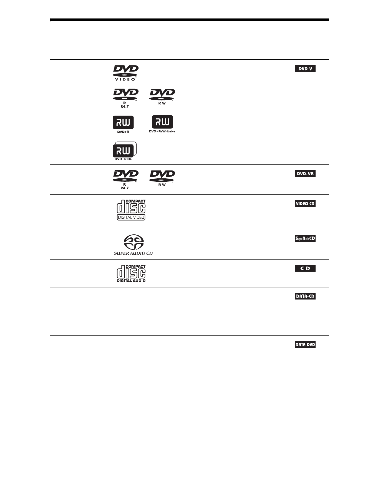
Playable Discs
1)
MP3 (MPEG1 Audio Layer 3) is a standard format defined by ISO/MPEG for compresses audio data. MP3 files
must be in MPEG1 Audio Layer 3 format.
2)
JPEG image files must conform to the DCF image file format. (DCF “Design rule for Camera File system”: Image
standards for digital cameras regulated by Japan Electronics and Information Technology Industries Association
(JEITA).)
Type Disc logo Characteristics Icon
DVD VIDEO • DVD VIDEO
• DVD-R/DVD-RW in DVD VIDEO
format or video mode
• DVD+R/DVD+RW in DVD VIDEO
format
VR (Video
Recording) mode
• DVD-R/DVD-RW in VR (Video
Recording) mode (except for DVD-R
DL)
VIDEO CD • VIDEO CD (Ver. 1.1 and 2.0 discs)
• Super VCD
• CD-R/CD-RW/CD-ROM in video CD
format or Super VCD format
Super Audio CD • Super Audio CD
CD • Audio CD
• CD-R/CD-RW in audio CD format
DATA CD – • CD-R/CD-RW/CD-ROM in DATA CD
format, containing MP3
files1), JPEG
image files
2)
, DivX video files, and
MPEG4 video files, and conforming to
ISO 9660
3)
Level 1/Level 2, or Joliet
(extended format)
DATA DVD – • DVD-ROM/DVD-R/DVD-RW/
DVD+R/DVD+RW in DATA DVD
format, containing MP3 files1), JPEG
image files2), DivX video files, and
MPEG4 video files, and conforming to
UDF (Universal Disk Format)

7
GB
3)
A logical format of files and folders on CD-ROMs, defined by ISO (International Organization for
Standardization).
Notes on discs
This product is designed to playback discs that conform to the Compact Disc (CD) standard.
DualDiscs and some of the music discs encoded with copyright protection technologies do not conform
to the Compact Disc (CD) standard, therefore, these discs may not be playable by this product.
The system cannot play the following discs:
• CD-ROM/CD-R/CD-RW other than those recorded in the formats listed on page 6
• CD-ROM recorded in PHOTO CD format
• Data part of CD-Extra
• CD Graphics disc
• DVD Audio
• DATA CD/DATA DVD that does not contain MP3 files, JPEG image files, DivX video files, or
MPEG4 video files
• DVD-RAM
•Blu-ray Disc
Also, the system cannot play the following discs:
• A DVD VIDEO with a different region code (page 8)
• A disc that has a non-standard shape (e.g., card, heart)
• A disc with paper or stickers on it
• A disc that has the adhesive of cellophane tape or a sticker still left on it
In some cases, CD-R/CD-RW/DVD-R/DVD-RW/DVD+R/DVD+RW cannot be played on this system
due to the recording quality or physical condition of the disc, or the characteristics of the recording
device and authoring software.
The disc will not play if it has not been correctly finalized. For more information, refer to the operating
instructions for the recording device.
Note that some playback functions may not work with some DVD+RWs/DVD+Rs, even if they have
been correctly finalized. In this case, view the disc by normal playback. Also some DATA CDs/DATA
DVDs created in Packet Write format cannot be played.
• This system can play a Multi Session CD when an MP3 file is contained in the first session. Any
subsequent MP3 files recorded in later sessions can also be played back.
• This system can play a Multi Session CD when a JPEG image file is contained in the first session.
Any subsequent JPEG image files recorded in later sessions can also be played back.
• If MP3 files and JPEG image files in music CD format or video CD format are recorded in the first
session, only the first session will be played back.
Example of discs that the system cannot play
Note about CD-R/CD-RW/DVD-R/DVD-RW/DVD+R/DVD+RW
About Multi Session CD

8
GB
Your system has a region code printed on the rear of the unit and will only play a DVD labeled with
the same region code.
A DVD VIDEO labeled will also play on this system.
If you try to play any other DVD VIDEO, the message [Playback prohibited by area limitations.] will
appear on the TV screen. Depending on the DVD VIDEO, no region code indication may be given even
though playing the DVD VIDEO is prohibited by area restrictions.
Some playback operations on a DVD or VIDEO CD may be intentionally set by software producers.
Since this system will play a DVD or VIDEO CD according to the disc contents the software producers
designed, some playback features may not be available. Be sure to read the operating instructions
supplied with the DVD or VIDEO CD.
Region code
Note about playback operations of a DVD or VIDEO CD
ALL
9
GB
Getting Started
Getting Started
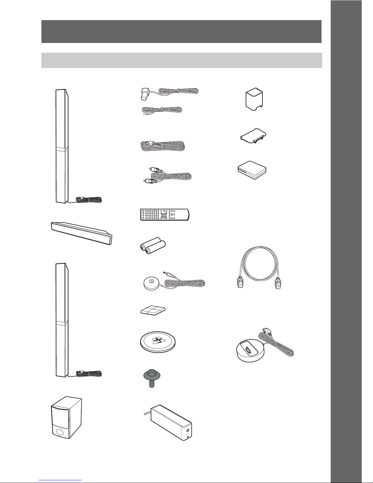
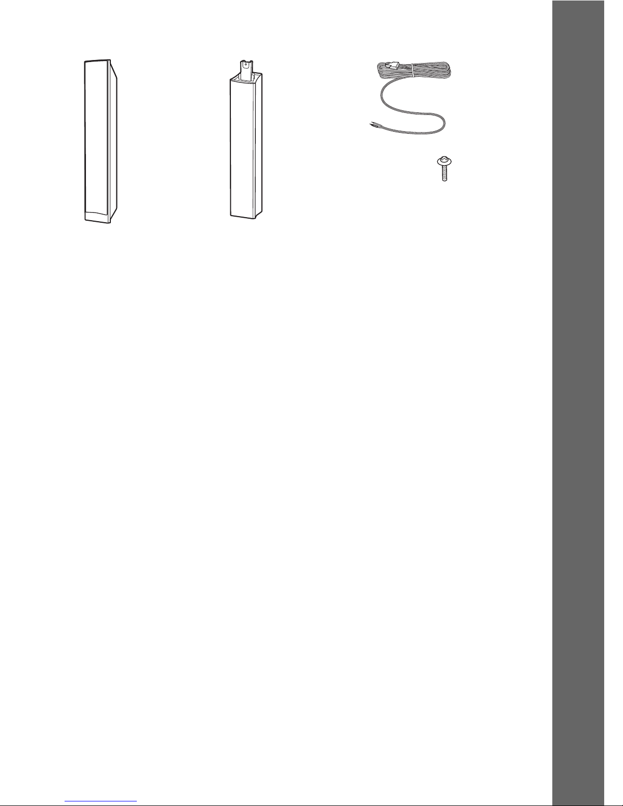
Unpacking
• Front speakers (2)
• Center speaker (1)
• Surround speakers (2)
• Subwoofer (1)
• FM wire antenna (aerial) (1)
• Speaker cords (2, green/
purple)
• Video cord (1)
• Remote commander
(remote) (1)
• R6 (size AA) batteries (2)
• Calibration mic (1)
• Foot pads (1 set)
• Bases (4)
• Screws (with washer) (12)
• Surround amplifier (1)
• Speaker cord cover (1)
• Speaker cord holder (1)
• Wireless transceivers (2)
• Operating Instructions
• Quick Setup Guide
For Singapore, Indonesian,
Malaysian, Hong Kong, Thai,
Taiwan, and Latin American
models
• HDMI cable (1)
For Australian models
• DIGITAL MEDIA PORT
adapter (TDM-iP20) (1)
• Operating Instructions for
the DIGITAL MEDIA
PORT adapter (TDM-iP20)
or
10
GB
Getting Started
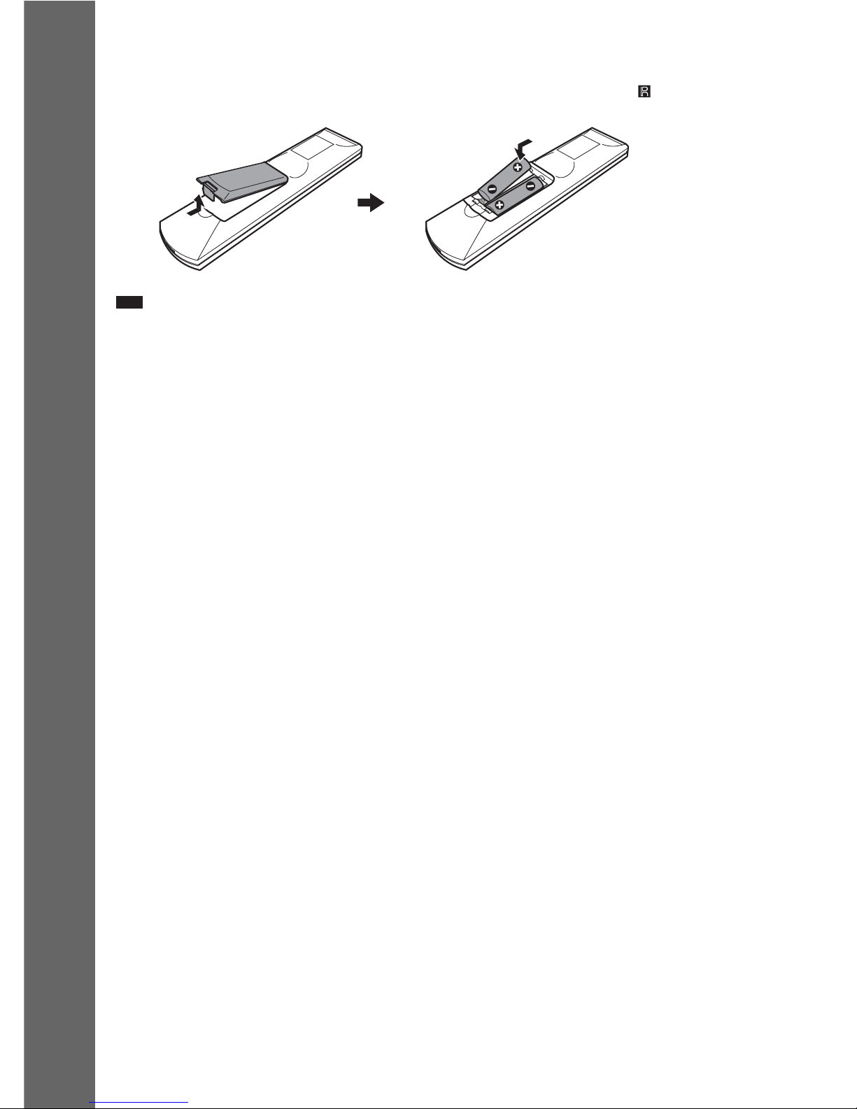
Inserting batteries into the remote
Insert two R6 (size AA) batteries (supplied) by matching the 3 and # ends on the batteries to the
markings inside the compartment. To use the remote, point it at the remote sensor on the unit.
Note
• Do not leave the remote in an extremely hot or humid place.
• Do not use a new battery with an old one.
• Do not drop any foreign object into the remote casing, particularly when replacing the batteries.
• Do not expose the remote sensor to direct sunlight or lighting apparatus. Doing so may cause a malfunction.
• If you do not intend to use the remote for an extended period of time, remove the batteries to avoid possible damage
from battery leakage and corrosion.
11
GB
Getting Started
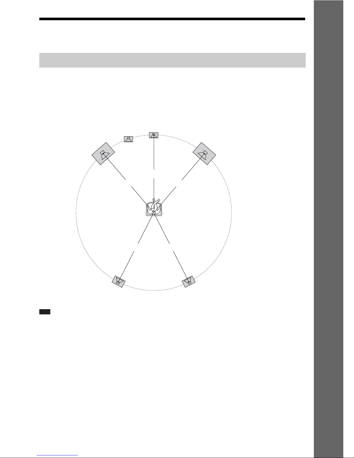
Step 1: Installing the System
For the best possible surround sound, place all speakers at the same distance from the listening position
(A). The distance can be between 0.0 to 7.0 meters.
If you cannot place the center speaker and surround speakers at the same distance as (A), place them
within 7.0 meters of the listening position.
The subwoofer can be placed anywhere in the room.
Note
• Use caution when placing the speakers and/or speaker stands attached to the speakers on a specially treated (waxed,
oiled, polished, etc.) floor, as staining or discoloration may result.
• Do not lean or hang on a speaker, as it may fall down.
Positioning the system
A
A
A
A
A
Front left speaker (L)
Front right speaker (R)
Center speaker
Subwoofer
Surround left speaker (L)
Surround right speaker (R)
12
GB
Getting Started
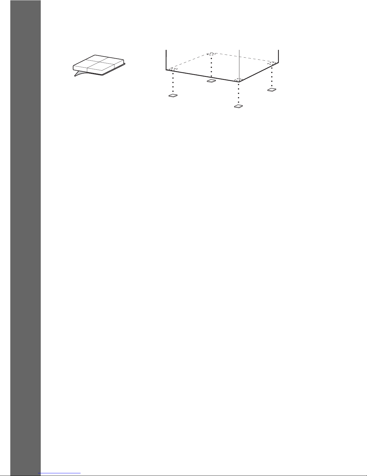
Attaching the foot pads to the subwoofer
Attach the foot pads (supplied) to the bottom of the subwoofer to stabilize the subwoofer and prevent
it from slipping.
,
Remove the foot pads from
the protective cover.
13
GB
Getting Started
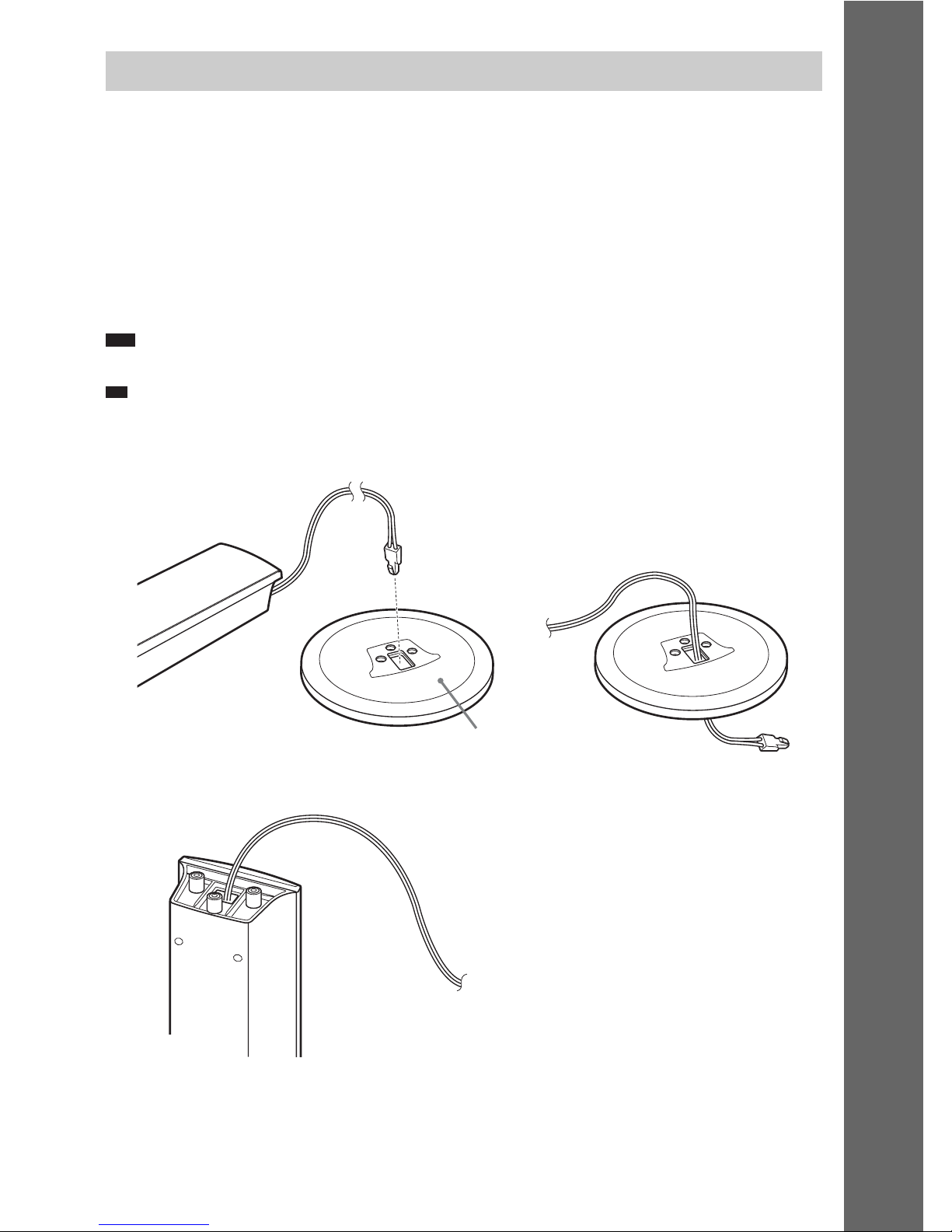
Before connecting the speakers, attach the speaker stand to the speaker.
(For the front and surround speakers)
Use the parts as follows:
• Front and surround speakers (4)
• Bases (4)
• Screws (with washer) (12)
For details of how to connect the speaker cords to the SPEAKER jacks, see page 19.
Note
• Spread a cloth on the floor to avoid damaging the floor when you assemble the speakers.
Ti
p
• You can use the speaker without the speaker stand by installing it on the wall (page 15).
1 Thread the speaker cord through the top hole in the base.
2 Turn the speaker upside down.
Assembling the speakers
Speaker cord
Top of the base
Speaker
,
Speaker
Speaker cord
14
GB
Getting Started
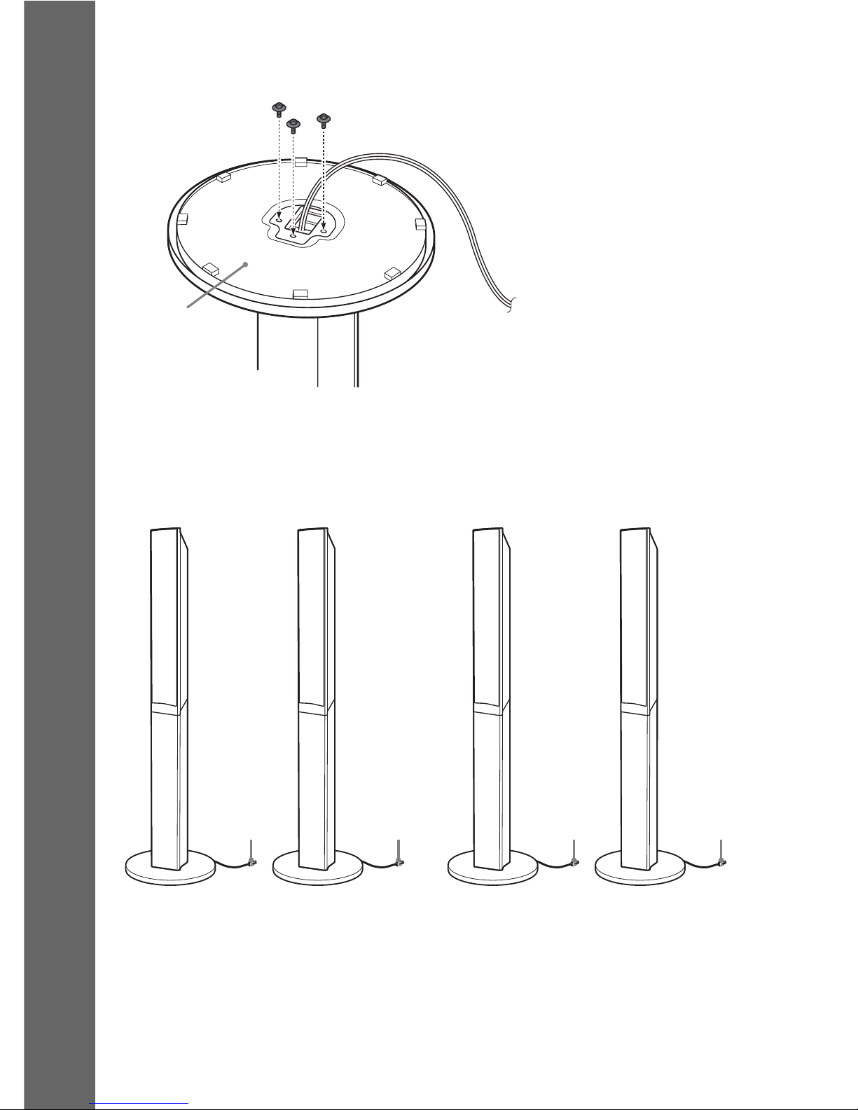
3 Place the base on the bottom of the speaker, then secure the base with three screws
(with washer).
Fully-assembled illustration
Speaker
Bottom of the
base
Screws (with washer)
Surround left speaker (L):
Blue label
White
Red
Surround right speaker (R)
:
Gray label
Front left speaker (L):
White label
Front right speaker (R):
Red label
Blue
Gray

15
GB
Getting Started
Caution
• Contact a screw shop or installer for information regarding the wall material or screws to be used.
• Use screws that are suitable for the wall material and strength. As a plaster board wall is especially fragile, attach
the screws securely to a beam. Install the speakers on a vertical and flat wall where reinforcement is applied.
• Sony is not responsible for accidents or damage caused by improper installation, insufficient wall strength or
improper screw installation, natural calamity, etc.
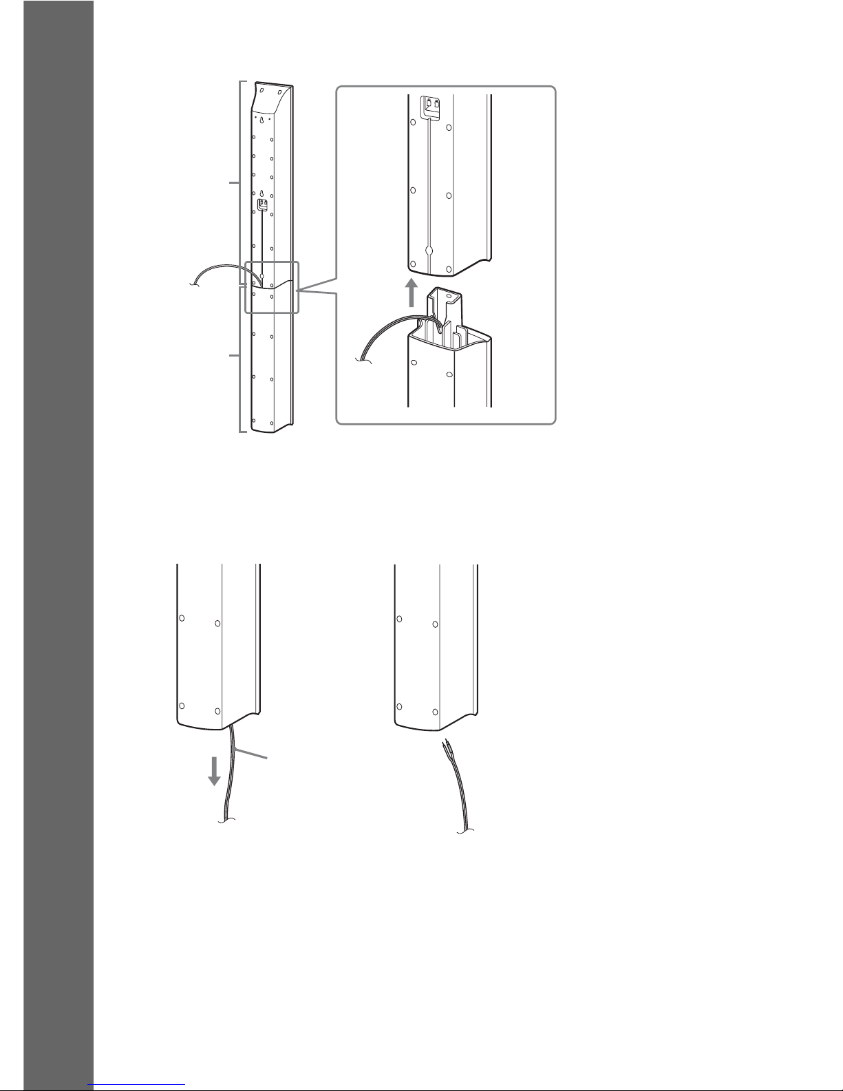
Before installing the front and surround speakers on a wall, you need to disassemble the speakers. You
can install the upper part of a speaker on a wall.
To disassemble the speaker
1 Disconnect the speaker cords from the speaker.
2 Remove the screw (pre-installed) at the rear of the speaker.
This screw is used when reassembling the speaker. Be sure not to lose the screw.
Installing the speakers on a wall
Rear of the speaker
Rear of the speaker
Screw
16
GB
Getting Started
3 Disassemble the speaker by lifting the upper part of the speaker.
4 Pull out the speaker cord from the bottom of the lower part of the speaker.
The removed speaker cord is used when installing the speaker on a wall.
Upper part
Lower part
Rear of the speaker
Lower part of the speaker
,
Speaker cord
17
GB
Getting Started
Fully-disassembled illustration
Upper part of
the speaker
Lower part of
the speaker
Speaker cord
Screw

18
GB
Getting Started
To install the speakers on a wall
Before installing the speakers on a wall, connect the speaker cord to the speaker.
Be sure to match the speaker cords to the appropriate terminals on the speakers: the speaker cord with
the color tube to 3, and the speaker cord without the color tube to #.
1 Prepare screws (not supplied) that are suitable for the hole on the back of each speaker.
See the illustrations below.
2 Fasten the screws to the wall.
3 Hang the speakers on the screws.
Color tube
Front left speaker (L): White
Front right speaker (R): Red
Center speaker: Green
Surround left speaker (L): Blue
Surround right speaker (R): Gray
30 mm (1 3/16 inches)
4 mm (
5
/32 inch)
Hole on the back of
the speaker
5 mm
(
7
/32 inch)
10 mm
(
13
/32 inch)
8 to 10 mm
(
11
/32 to 13/32
inch
)
219 mm
(8
5
/8 inches)
For the center speaker
210 mm
(8
3
/8
inches
)
For the other speakers
8 to 10 mm
(
11
/32 to 13/32
inch
)
5 mm
(
7
/32 inch)
10 mm
(
13
/32 inch)
Hole on the back of
the speaker
Rear of the speaker

19
GB
Getting Started
Step 2: Connecting the System
For connecting the system, read the information on the following pages.
Do not connect the AC power cord (mains lead) of the unit to a wall outlet (mains) until all the other
connections are made.
Note
• When you connect another component with a volume control, turn down the volume of the other components to a
level where sound is not distorted.
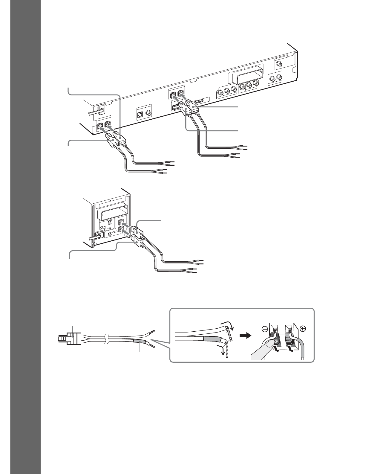
The connector of the speaker cords and the color tube are color-coded depending on the type of speaker.
Connect the speaker cords to match the color of the SPEAKER jacks of the unit.
Be sure to match the speaker cords to the appropriate terminals on the speakers: the speaker cord with
the color tube to 3, and the speaker cord without the color tube to #. Do not catch the speaker cord
insulation (rubber covering) in the speaker terminals.
Connecting the speakers
20
GB
Getting Started
To connect speaker cords to the unit
When connecting to the unit, insert the connector until it clicks.
To connect speaker cords to the speaker
R
S
U
R
R
O
U
N
D
S
E
L
E
C
T
O
R
S
-A
IR
ID
E
Z
W
-R
T
10
S
P
E
A
K
E
R
S
U
R
R
O
U
N
D
PAI
RING
C
B
A
S
U
R
R
O
U
N
D
B
A
C
K
L
CENTER
S
U
B
W
O
O
F
E
R
H
D
M
I O
U
T
S
P
E
A
K
E
R
COAXIAL 75
FM
A
N
T
E
N
N
A
D
M
P
O
R
T
DC5V
0.7A MAX
DIGITAL IN
COAXIAL
OPTICAL
T
V
AUDIO IN
P
B
/C
B
P
R
/C
R
Y
L
R
V
ID
E
O
O
U
T
T
V
C
O
M
P
O
N
E
N
T
V
ID
E
O
O
U
T
AUDIO IN LR
S
A
T
/C
A
B
L
E
E
Z
W
-
R
T
1
0
FRONT R FRONT L
S
P
E
A
K
E
R
Green
(Center speaker)
Purple
(Subwoofer)
White
(Front left speaker (L))
Red
(Front right speaker (R))
Gray
(Surround right speaker (R))
Blue
(Surround left speaker (L))
Rear panel of the unit
Rear panel of the surround amplifier
Color tube
(+)
(–)
Connector
Rear of the speaker

21
GB
Getting Started
This connection sends a video signal to the TV.
Depending on the jacks on your TV, select the connection method.
* The HDMI cable is supplied with Singapore, Indonesian, Malaysian, Hong Kong, Thai, Taiwan, and Latin
American models only.
Method 1: Video cord (A) connection
This is the basic connection.
Method 2: HDMI* cable (B) and video cord (A) connection
If your TV has an HDMI jack, connect to the TV both with an HDMI cable and video cord. Picture
quality will be improved compared to using only the video cord connection.
When connecting with the HDMI cable, you need to select the type of output signal (page 34).
To view images from the DIGITAL MEDIA PORT adapter, you need to connect to the TV with the
video cord. Video signals from the DIGITAL MEDIA PORT adapter are not output via the HDMI OUT
jack.
* HDMI (High-Definition Multimedia Interface)
Method 3: Component video cable (C) and video cord (A) connection
If your TV does not have an HDMI jack, but has component video input jacks, connect to the TV both
with a component video cable and video cord. Picture quality will be improved compared to using only
the video cord connection.
When connecting with the component video cable, you need to set the type of output signal to
progressive format (page 34).
To view images from the DIGITAL MEDIA PORT adapter, you need to connect to the TV with the
video cord. Video signals from the DIGITAL MEDIA PORT adapter are not output via the
COMPONENT VIDEO OUT jack.
Connecting the TV (Video connection)
CENTER
S
U
B
W
O
O
F
E
R
H
D
M
I O
U
T
S
P
E
A
K
E
R
COAXIAL 75
FM
A
N
T
E
N
N
A
D
M
P
O
R
T
DC5V
0.7A MAX
DIGITAL IN
COAXIAL
OPTICAL
T
V
AUDIO IN
P
B
/C
B
P
R
/C
R
Y
L
R
V
I
D
E
O
O
U
T
T
V
C
O
M
P
O
N
E
N
T
V
ID
E
O
O
U
T
AUDIO IN
LR
S
A
T
/C
A
B
L
E
E
Z
W
-
R
T
1
0
FRONT R
FRONT L
S
P
E
A
K
E
R
To the HDMI IN jack
of the TV.
To the video input jack of
the TV.
A Video cord (supplied)
B HDMI cable*
To the component
video input jacks of
the TV.
C Component video cable
(not supplied)

22
GB
Getting Started
To change the color system (PAL or NTSC) (Asian, Australian, and
Middle Eastern models only)
Depending on the TV to be connected, you may be required to select either PAL or NTSC for the color
system.
The initial setting of the system for Australian and Middle Eastern models is PAL.
The initial setting of the system for Asian models is NTSC.
1 Turn off the system by pressing "/1.
2 Turn on the system by pressing "/1 on the unit while turning OPERATION DIAL on the
unit counterclockwise.
Each time you perform this operation, the color system toggles between PAL and NTSC.
“NTSC” lights up in the front panel display when the color system is set to NTSC.
23
GB
Getting Started
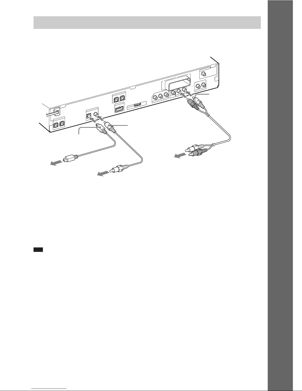
This connection sends an audio signal to the unit from the TV. To listen to TV sound via the system,
perform this connection.
Method 1: Audio cord (D) connection
This is the basic connection and sends an analog audio signal.
Method 2: Digital optical cord (E) or digital coaxial cord (F) connection
When the TV has a digital optical or coaxial output jack, you can improve sound quality by connecting
with a digital optical or coaxial cord in addition to an audio cord connection.
Note
• The system can accept both digital and analog signals. Digital signals have priority over analog signals. (COAXIAL
has priority over OPTICAL.) If the digital signal ceases, the analog signal will be processed after 2 seconds.
Connecting the TV (Audio connection)
CENTER
S
U
B
W
O
O
F
E
R
H
D
M
I O
U
T
S
P
E
A
K
E
R
COAXIAL 75
FM
A
N
T
E
N
N
A
D
M
P
O
R
T
DC5V
0.7A MAX
DIGITAL IN
COAXIAL
OPTICAL
T
V
AUDIO IN
P
B
/C
B
P
R
/C
R
Y
L
R
V
ID
E
O
O
U
T
T
V
C
O
M
P
O
N
E
N
T
V
ID
E
O
O
U
T
AUDIO IN
LR
S
A
T
/C
A
B
L
E
E
Z
W
-
R
T
1
0
FRONT R FRONT L
S
P
E
A
K
E
R
To the digital optical out
jack of the TV.
To the audio out jacks of
the TV.
D Audio cord (not
supplied)
E Digital optical cord (not
supplied)
To the digital coaxial out jack
of the TV.
F Digital coaxial cord (not
supplied)
24
GB
Getting Started
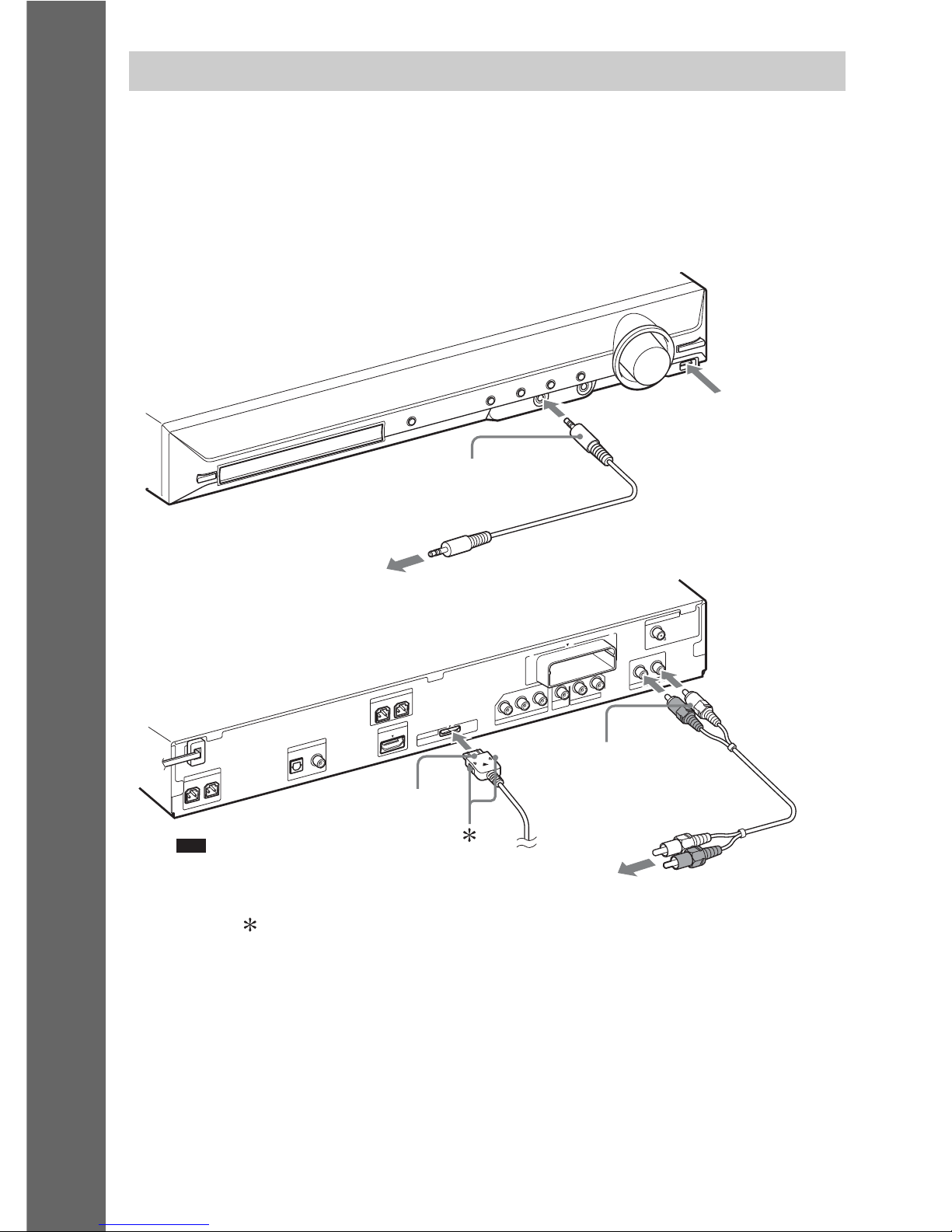
You can enjoy connected components via the system’s speakers.
Portable audio source (not supplied): G
USB device (not supplied): H
DIGITAL MEDIA PORT adapter: I (TDM-iP20 is supplied with Australian models. You can also
use other DIGITAL MEDIA PORT adapters.)
VCR, digital satellite receiver, or PlayStation, etc. (not supplied): J
Connecting the other components
CENTER
S
U
B
W
O
O
F
E
R
H
D
M
I O
U
T
S
P
E
A
K
E
R
COAXIAL 75
FM
A
N
T
E
N
N
A
D
M
P
O
R
T
DC5V
0.7A MAX
DIGITAL IN
COAXIAL
OPTICAL
T
V
AUDIO IN
P
B
/C
B
P
R
/C
R
Y
L
R
V
ID
E
O
O
U
T
T
V
C
O
M
P
O
N
E
N
T
V
ID
E
O
O
U
T
AUDIO IN
L
R
S
A
T
/C
A
B
L
E
E
Z
W
-
R
T
1
0
FRONT R
FRONT L
S
P
E
A
K
E
R
I DIGITAL MEDIA PORT
adapter (page 83)
To a portable audio source
G Stereo mini-plug cord
(not supplied)
H Connect a USB
device (page 71).
Note
• Connect the DIGITAL MEDIA PORT
adapter so that the V marks are aligned.
When disconnecting, pull out while
pressing .
To the audio out jacks of the VCR, digital satellite
receiver, or PlayStation, etc.
J Audio cord (not
supplied)
25
GB
Getting Started
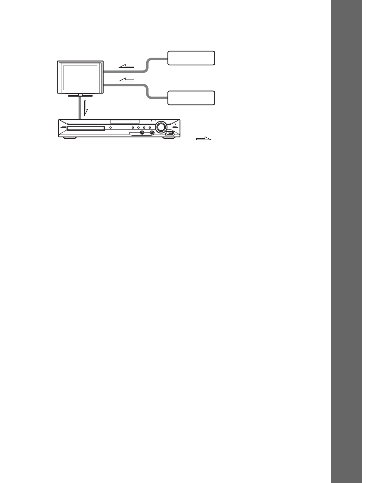
If your TV has multiple audio/video inputs
You can enjoy sound with the speakers of the system through the connected TV. Connect the
components as follows.
Select the component on the TV. For details, refer to the operating instructions of the TV.
If the TV does not have multiple audio/video inputs, a switcher will be necessary to receive sound from
more than one component.
System
:Signal flow
VCR, digital satellite receiver,
PlayStation, etc.
TV
VCR, digital satellite receiver,
PlayStation, etc.
26
GB
Getting Started
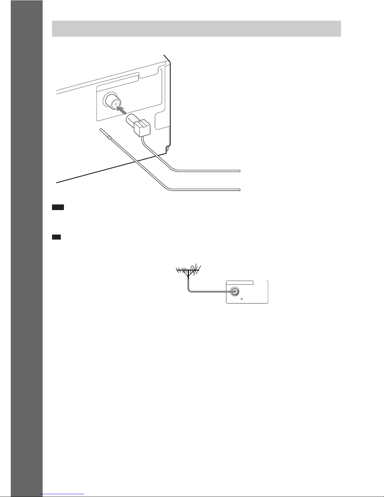
Note
• Be sure to fully extend the FM wire antenna (aerial).
• After connecting the FM wire antenna (aerial), keep it as horizontal as possible.
Ti
p
• If you have poor FM reception, use a 75-ohm coaxial cable (not supplied) to connect the unit to an outdoor FM
antenna (aerial) as shown below.
Connecting the antenna (aerial)
COAXIAL 75
FM
ANTENNA
or
FM wire antenna (aerial)
(supplied)
COAXIAL 75
FM
ANTENNA
Outdoor FM antenna (aerial)
Unit
27
GB
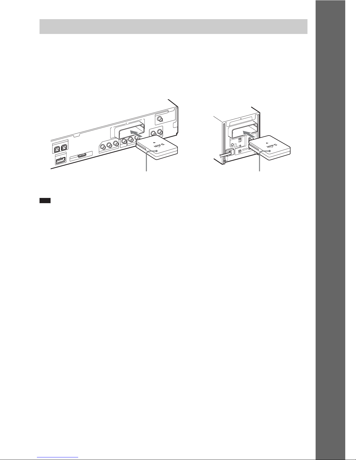
Getting Started
You can transmit sound from the unit to an S-AIR product, such as a surround amplifier or S-AIR
receiver.
To transmit sound from the unit, you need to insert the wireless transceivers into the unit, surround
amplifier, and S-AIR receiver.
For details of S-AIR products, see “Using an S-AIR Product” (page 84).
Note
• When you insert the wireless transceiver, make sure that the AC power cord (mains lead) is not connected to a wall
outlet (mains).
• Do not touch the terminals of the wireless transceiver.
• Insert the wireless transceiver so that the V marks are aligned.
• Do not insert anything other than the wireless transceiver into the EZW-RT10 slot.
Inserting the wireless transceiver
R
S
U
R
R
O
U
N
D
S
E
L
E
C
T
O
R
S
-A
IR
ID
E
Z
W
-R
T
10
S
P
E
A
K
E
R
S
U
R
R
O
U
N
D
PAIR IN G
C
B
A
S
U
R
R
O
U
N
D
B
A
C
K
L
H
D
M
I O
U
T
COAXIAL 75
FM
A
N
T
E
N
N
A
D
M
P
O
R
T
DC5V
0.7A MAX
AUDIO IN
P
B
/C
B
P
R
/C
R
Y
LR
V
ID
E
O
O
U
T
T
V
C
O
M
P
O
N
E
N
T
V
ID
E
O
O
U
T
AUDIO IN
LR
S
A
T
/C
A
B
L
E
E
Z
W
-
R
T
1
0
FRONT R FRONT L
S
P
E
A
K
E
R
Rear panel of the unit
Rear panel of the surround
amplifier
Wireless
transceiver
Wireless
transceiver
28
GB
Getting Started
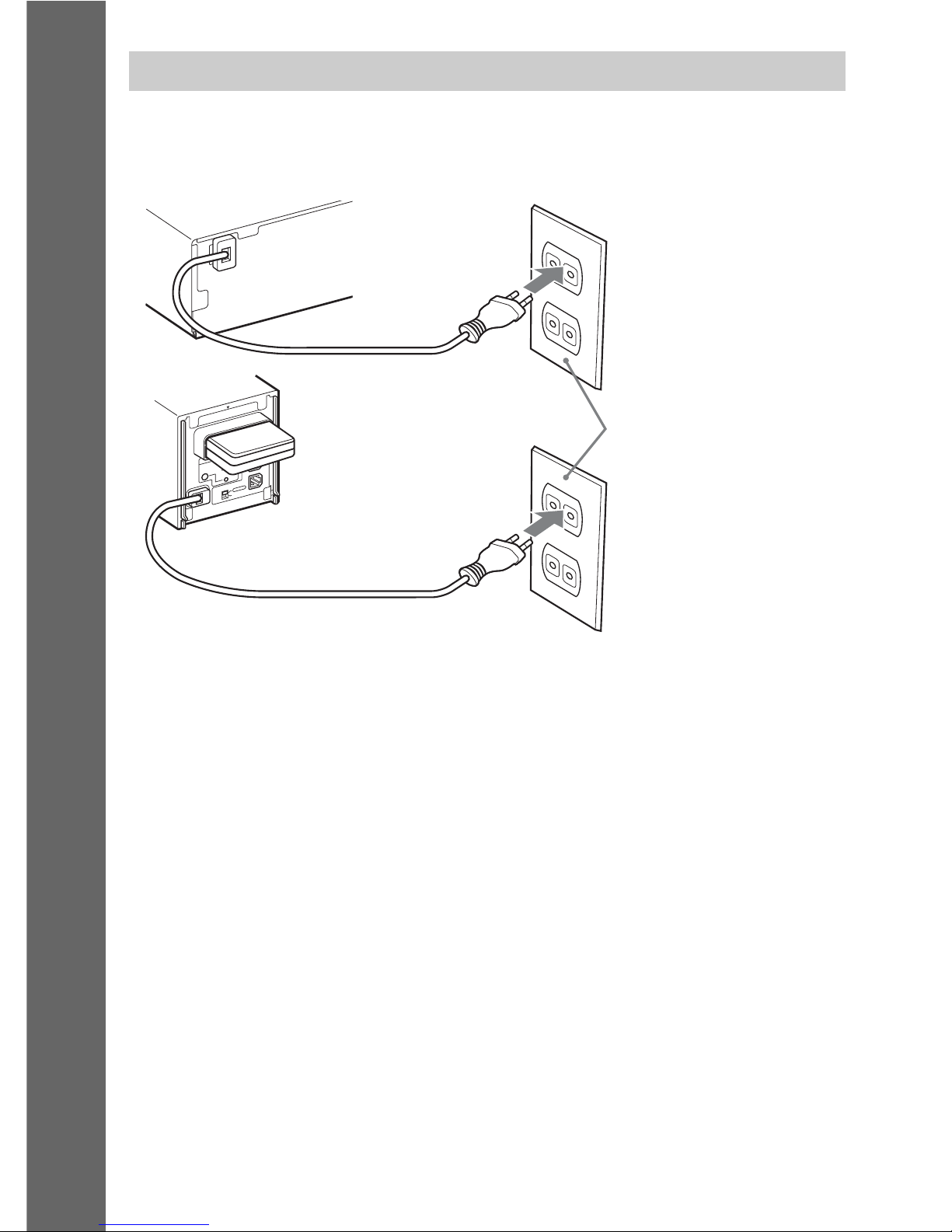
Before connecting the AC power cords (mains leads) of the unit and the surround amplifier to a wall
outlet (mains), connect the front, center speakers and subwoofer to the unit and surround speakers to
the surround amplifier.
Connecting the AC power cords (mains leads)
R
S
U
R
R
O
U
N
D
S
E
L
E
C
T
O
R
S
-A
IR
ID
E
Z
W
-
R
T
10
S
P
E
A
K
E
R
S
U
R
R
O
U
N
D
PAI
RING
C
B
A
S
U
R
R
O
U
N
D
B
A
C
K
L
Wall outlet (mains): The shape of
the wall outlet (mains) differs
depending on the area.
Rear panel of the unit
Rear panel of the
surround amplifier

29
GB
Getting Started
After connecting the AC power cord (mains lead), the demonstration appears in the front panel display.
Setting the demonstration mode to on/off
1 Press [/1 on the unit.
The system turns on.
2 Press SYSTEM MENU.
3 Press X/x repeatedly until “DEMO” appears in the front panel display, then press or
c.
4 Press X/x to select a setting.
•“DEMO ON”: On.
• “DEMO OFF”: Off.
5 Press .
The setting is made.
6 Press SYSTEM MENU.
The system menu turns off.
Ti
p
• When you purchase the system new, or if the system is at its factory default settings (ex., after performing “COLD
RESET” (page 102)), you can turn off the demonstration simply by pressing [/1 on the remote.
About the demonstration
30
GB
Getting Started
Step 3: Setting up the
Wireless System
To use the wireless system, you need to set up
the surround amplifier. Before setting, make
sure that the wireless transceivers are inserted
into the unit and the surround amplifier correctly
(page 27).
This wireless system is called “S-AIR.” For
details of the S-AIR function, see “Using an
S-AIR Product” (page 84).
The unit transmits sound to the surround
amplifier that is connected to the surround
speakers. To establish sound transmission,
perform the following Steps.
1 Press "/1 on the unit.
The system turns on.
2 Set the SURROUND SELECTOR switch
of the surround amplifier to
SURROUND.
3 Set the S-AIR ID switch of the surround
amplifier to A.
4 Press POWER on the surround
amplifier.
The POWER / ON LINE indicator turns
green. If it doesn’t, check the transmission
status as follows.
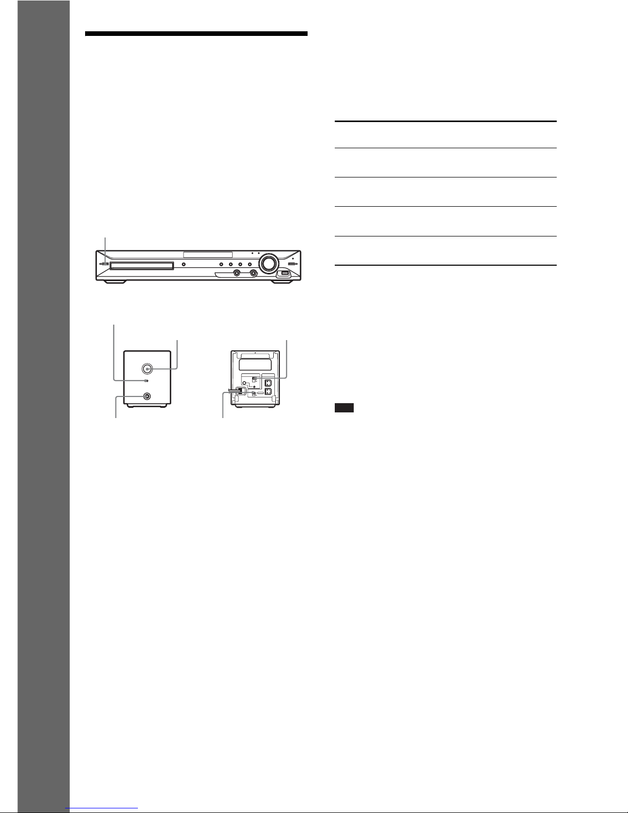
To check the transmission status
You can check the status of sound transmission
between the unit and surround amplifier by
observing the POWER / ON LINE indicator of
the surround amplifier.
For details of the surround amplifier, see
“Surround amplifier operation” (page 114).
To enjoy sound by using
headphones
You can enjoy the system’s sound by connecting
the headphones to the PHONES jack on the
surround amplifier.
Note
• The volume of the unit may become minimum if you
turn off the surround amplifier while the headphones
are connected to the surround amplifier, or radio
reception is poor. In this case, “HP NO LINK” and
“VOLUME MIN” appear alternately in the front
panel display. Check radio reception, and set the
volume again.
When you use multiple S-AIR
products
See “Establishing sound transmission between
the unit and S-AIR sub unit (ID setting)”
(page 84).
To attach the cover to the
surround amplifier
After connecting and setting, you can attach the
cover to the surround amplifier for organizing
and storing excess speaker cords.
"/1
POWER
POWER/ON LINE
PHONES
R
SURROUND SELECTOR
S-AIR ID
EZW-RT
10
SPEAKER
SURROUND
PAIRING
C
B
A
SURROUND
BACK
L
POWER
POWER / ON LINE
Indicator
SURROUND
SELECTOR switch
S-AIR ID switch
PHONES jack
POWER / ON LINE
indicator
Status
Turns green. Sound transmission is
established.
Flashes green. Sound transmission is not
established.
Turns red. The surround amplifier does
not output sound.
Turns off. The surround amplifier turns
off or its protection is active.
 Loading...