

Sony DAV-DZ200 User Manual
2-590-885-12(1)
DVD Home Theatre
System
Operating Instructions
DAV -DZ200
©2005 Sony Corporation
3
WARNING
To prevent fire or shock hazard, do not
expose the unit to rain or mo ist u r e.
Do not install the appliance in a confined space, such
as a bookcase or built-in cabinet.
To prevent fire, do not cover the ventil at ion of the
apparatus with news papers, table-cloths, curtains, etc.
And don’t place lighted candle s on the apparatus.
To prevent fire or shock hazard, do not place obje c ts
filled with liquids, such as vases , on the ap pa ratus.
Don’t throw away the battery with
general house waste, dispose of it
correctly as chemical waste.
This appliance is
classified as a CLASS 1
LASER product. This
marking is locat ed on the
rear of the unit.
Precautions
Safety
• If anything falls into the cabinet, unplug the unit and
have it checked by qualified person nel before
operating it any further.
• The unit is not disconnected from the AC power
source (mains) as long as it is connected to the wall
outlet (mains), even if the u nit itself has been turned
off.
• U nplug the unit from the wall outlet if you do not
intend to use it for an extended period of time. To
disconnect the cord, pull it out by the plug, never by
the cord.
Installing
• Allow adequate air circulation to prevent internal
heat buildup.
• Do not place the unit on surfaces (rugs, blankets, etc.)
or near materials (curtains, draperies) that may block
the ventilation slots.
• D o not install the unit near heat sources such as
radiators, or air ducts, or in a place subject to direct
sunlight, excessive dust, mechanical vibration, or
shock.
• D o n ot install the unit in an inclined posit ion. It is
designed to be operated in a horizontal position only.
• Keep the unit and discs away from equipment with
strong magnets, such as microwave ovens, or large
loudspeakers.
• Do not pla c e hea vy objects on the unit.
• If the unit is brought directly from a cold to a warm
location, moisture may condense inside the DVD
Home Theatre System and cause d amage to the
lenses. When you first install the unit, or when you
move it from a cold to a warm location, wait for about
30 minutes before operating th e unit.
GB
2

Welcome!
Thank you for purchasing Sony DVD Home
Theatre System. Before operating this system,
please read this manual thoroughly and retain it
for future re ference.
GB
3

Table of Contents
Welcome!................................................ 3
About This Manual.................................6
This System Can Play the Following
Discs .................................................6
Guide to the Control Menu Display......10
Getting Started
Unpacking.............................................13
Inserting Batteries into the Remote.......13
Hookup Overview.................................14
Step 1: Speaker System Hook up...........15
Step 2: Antenna (Aerial) Hookup.........24
Step 3: TV Hookup.................. .... .........25
Step 4: Other Component Hookup........30
Step 5: Connecting the AC Power Cord
(Mains Lead)...................................32
Step 6: Turning off
the Demonstration...........................32
Step 7: Performing the Quick Setup.....33
Speaker Setup........................................35
Playing Discs
Playing Discs........................................36
Using the DVD’s Menu...................... ..40
Selecting [ORIGINAL] or [PLAY LIST]
on a DVD-RW............... .... .............41
Selecting a Playback Area for a Super
Audio CD........................................41
Playing VIDEO CDs with PBC Functions
(Ver.2.0)..........................................42
(PBC Playback)
About MP3 Audio Tracks and JPEG
Image Files .....................................43
Playing DATA CDs with MP3 Audio
Track and JPEG Image Files..........45
Playing Audio Tracks and Images as a
Slide Show with Sound...................47
Enjoying DivX® Videos.......................49
Adjusting the Delay Between the Picture
and Sound.......................................51
(A/V SYNC)
Searching for a Particular Point on
a Disc..............................................52
(Scan, Slow-motion Play, Freeze
Frame)
Searching for a Title/Chapter/Track/
Scene, etc........................................ 53
Searching by Scene............................... 55
(Picture Navigation)
Viewing Information About the Disc...56
Sound Adjustments
Changing the Sound .............................60
Enjoying Surround Sound by Using Sound
Field................................................ 62
Enjoying TV or VCR Sound from All
Speakers ......................................... 64
Using the Sound Effect.........................65
Using Various Additional
Functions
Changing the Angles............................66
Displaying the Subtitles........................66
Locking Discs....................................... 67
(CUSTOM PARENTAL
CONTROL, PARENTAL
CONTROL)
Other Operations
Controlling the TV with the Supplied
Remote ...........................................71
Using the THEATRE SYNC
Function.......................................... 72
Enjoying the S ound of Other
Components....................................73
Enjoying the Radio...............................75
Using the Sleep Timer..........................77
Changing the Brightness of the Front
Panel Display..................................77
Returning to the Default Settings......... 78
GB
4

Settings and Adj ustments
Using the Setup Display........................79
Setting the Display or Sound Track
Language ........................................80
[LANGUAGE SETUP]
Settings for the Display.........................81
[SCREEN SETUP]
Custom Settings....................................82
[CUSTOM SETUP]
Settings for the Speakers.......................83
[SPEAKER SETUP]
Additional Information
Precautions............................................86
Notes about the Discs............................87
Troubleshooting....................................87
Self-diagnosis Function........................90
(When letters/numbers appear in
the display)
Specifications........................................91
Glossary ................................................ 92
Language Code List..............................95
Index to Parts and Controls...................96
DVD Setup Display List.....................100
AMP Menu List..................................101
Index ...................................................102
GB
5
About This Manual
This System Can Play the
• The instructions in this manual describe the
controls on the rem ote. You can also use the
controls on the system if they have the same or
similar names as those on the remote.
• The Control Menu items may be different
depending on the area.
• “DVD” may be used as a general term for
DVD VIDEOs, DVD+RWs/DVD+Rs, and
DVD-RWs/DVD-Rs.
• Measurements are expressed in feet (ft) for
North American models.
• The following symbols are used in this
manual.
Symbol Meaning
Functions available for DVD
VIDEOs, DVD-Rs/DVD-RWs in
video mode, and DVD+Rs/
DVD+RWs
Functions available for DVD-RWs
in VR (Video Recording) mode
Functions available for VIDEO
CDs (including Super VCDs or CDRs/CD-RWs in video CD format or
Super VCD format)
Functions available for Super Audio
CDs
Functions available for music CDs
or CD-Rs/CD- RWs in music CD
format
Functions available for DATA CDs
(CD-ROMs/CD-Rs/CD-RWs
containing MP3*
JPEG image files, and DivX*
video files)
Functions available for DATA
DVDs (DVD-Rs/DVD-RWs/
DVD+Rs/DVD+RWs) containing
2*3
DivX*
*1MP3 (MPEG1 Audio Layer 3) is a standard format
defined by ISO/MPEG which compresses audio
data.
®
is a video file compression technology,
*2DivX
developed by DivXNetworks, Inc.
*3DivX, DivX Certified, and associated logos are
trademarks of DivXNetworks, Inc. and ar e used
under license.
1
audio tracks,
video files
2*3
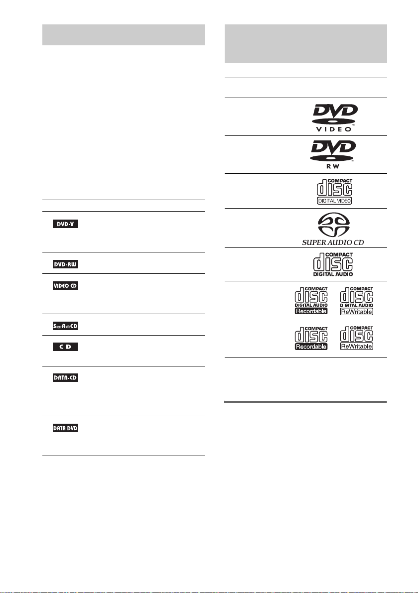
Following Discs
Format of
discs
DVD VIDEO
DVD-RW
VIDEO CD
Super Audio
CD
Audio CD
CD-R/CD-RW
(audio data)
(MP3 files)
(JPEG files)
The “DVD VIDEO” logo and “DVD-RW” logo are
trademarks.
Note about CDs/DVDs
The system can play CD-ROMs/CD-Rs/CDRWs recor d e d in the followin g formats:
– audio CD format
– video CD format
– MP3 audio tracks, JP EG i m age files, and
DivX video files of format conforming to ISO
9660 Level 1/Level 2, or its extended format,
Joliet
Disc logo
GB
6

The system can play DVD-ROMs/DVD+RWs/
DVD-RWs/DVD+Rs/DVD-Rs recorded in the
following formats:
– DivX video files of format conforming to
UDF.
Example of discs that the system cannot play
The system cannot play the following discs:
• CD-ROMs/CD-Rs/CD-RWs other than those
recorded in the formats listed on page 6
• CD-ROMs recorded in PHOTO CD format
• Data part of CD-Extras
• DVD Audios
• DVD-RAMs
Also, the system can not play the following
discs:
• A DVD VIDEO with a different region code
(page 8, 94).
• A disc that has a non-standard shape (e.g.,
card, heart).
• A disc with paper or stickers on it.
• A disc that has the adhesive of cellophane tape
or a sticker still left on it.
Notes about CD-R/CD-RW/DVD-R/
DVD-RW/DVD+R/DVD+RW
In some cases, CD-R/CD-RW/DVD-R/DVD-RW/
DVD+R/DVD+RW cannot be played on this system
due to the recording quality or physical condition of the
disc, or the characteristics of the recording device and
authoring software.
The disc will not play if it has not been correctly
finalized. For more informat ion, se e the ope r ating
instructions for the recor d ing device.
Note that discs created in the Packet Write format
cannot be played.
Music discs encoded with
copyright protection
technologies
This product is designed to play back discs that
conform to the Compact Disc (CD) standard.
Recently, various music discs encoded with copyright
protection technol o gies ar e mark eted by some record
companies. Please be aware that am ong those discs,
there are some that do not conform to the CD standard
and may not be playable by this product.
Note on DualDisc
A DualDisc is a two sided disc product which mates
DVD recorded material on one side with digital audio
material on the other side.
However, since the audio material side does not
conform to the Co mpact Dis c (CD) stan dard, pl ayback
on this product is not guaranteed.
Note on PBC (Playback Control) (VIDEO CDs)
This system conforms to Ver. 1.1 and Ver. 2.0 of
VIDEO CD standards. You can enjoy two kinds
of playback depending on the disc type.
Disc type You can
VIDEO CDs
without PBC
functions
(Ver. 1.1 discs)
VIDEO CDs
with PBC
functions
(Ver. 2.0 discs)
Enjoy video playback (moving
pictures) as well as music.
Play interactive software using
menu screens displayed on the
TV screen (PBC Playback), in
addition to the video playback
functions of Ver. 1.1 discs.
Moreover, you can play highresolution still pictures, if they
are included on the disc.
About Multi Session CD
• This system can play Multi Session CDs when
an MP3 audio track is contained in the first
session. Any sub sequent MP3 audio tracks
recorded in later sessions can also be played
back.
• This system can play Multi Session CDs when
a JPEG image file is contained in the first
session. Any sub sequent JPEG image files
recorded in later sessions can also be played
back.
• If audio tracks and images in music CD format
or video CD format are recorded in the first
session, only the first session will be played
back.
GB
7

About the Super Audio CD
Super Audio CD is a ne w hi gh-quality audio
disc standard where music is recorded in the
DSD (Direct Stream Digital) format
(conventional C D s are recorded in the PCM
format). The DSD format, using a sampling
frequency 64 times hi gher than that of a
conventional CD, and with 1-bit quantization,
achieves both a wide frequency range and a wide
dynamic range across the audible frequenc y
range, and so pro vi des music reproduction
extremely faithful to the original sound.
Types of Super Audio CDs
There are two types of discs, depending on the
Super Audio CD layer and CD layer
combination.
• Super Audio CD l ayer: A high-density
signal layer for Super Audio CD
•CD layer*
1
: A layer that is readable by a
conventional CD pl ayer
Single layer disc
(a disc with a single Super Audio CD layer)
Super Audio CD
layer
Hybrid disc*
(a disc with an Super Audio CD layer and a CD
layer)
2
3
CD layer*
2 channel area*
Multi channel area*
*1You can play the CD layer on a conventional CD
player.
*2Since both layers are on one side, it is not necessary
to turn the disc over.
*3To select a lay er, see “Selecti ng a Playback Ar ea for
a Super Audio CD” (page 41).
*4To select an are a, see “Select ing a Playback Ar ea for
a Super Audio CD” (page 41).
4
4
Super Audio CD
layer
Region code
Your system has a region code printed on the
back of the unit and will only play DVDs labeled
with the same region code.
DVD VIDEOs labeled will also play on this
system.
If you try to play any other DVD VIDEO, the
message [Playback prohibited by area
limitations.] will appear on the TV screen.
Depending o n the DVD V IDEO, no re gion co de
indicati on may be given e ven though pl aying the
DVD VIDEO is prohibited by area restrictions.
ALL
Super Audio CD
layer*
A Super Audio CD la ye r consists of the 2
channel area or th e m ul ti-channel area.
• 2 channel area: An area in which 2 channel
stereo tracks are recorded
• Multi-channel area: An area in which mul tichannel (up to 5. 1 channels) tracks are
recorded
GB
8
3
Note on playba ck operations of DVDs and VIDEO CDs
Some playback operations of DVDs and VIDEO
CDs may be intentionally set by software
producers. Since this system plays DVDs an d
VIDEO CDs according to the disc cont ents the
software pr oducers design ed, some playback
features may not be available. Also, refer to the
instructions supplied with the DVDs or VIDEO
CDs.

Copyrights
This product i ncorporates copyright prot ection
technology that is protected by U.S. patents and
other intellectual property rights. Use of this
copyright protection technology must be
authorized by Macrovision, and is intended for
home and other limited viewing uses only unless
otherwise author ized by Macrovision. Rever se
engineer i ng or disassembly is prohibi t ed.
This system incorporates with Dolby*
and Dolby Pro Logic (II) adaptive matrix
surround decoder and the DTS*2 Digita l
Surround System .
*1Manufactured under license from Dolby
Laboratories.
“Dolby,” “Pro Logic,” and the double-D symbol are
trademarks of Dolby Laboratories.
*2Manufactured under license from Digital Theater
Systems, Inc.
“DTS” and “DTS Digital Surround” are trademarks
of Digital Theater Systems, Inc.
1
Digital
GB
9
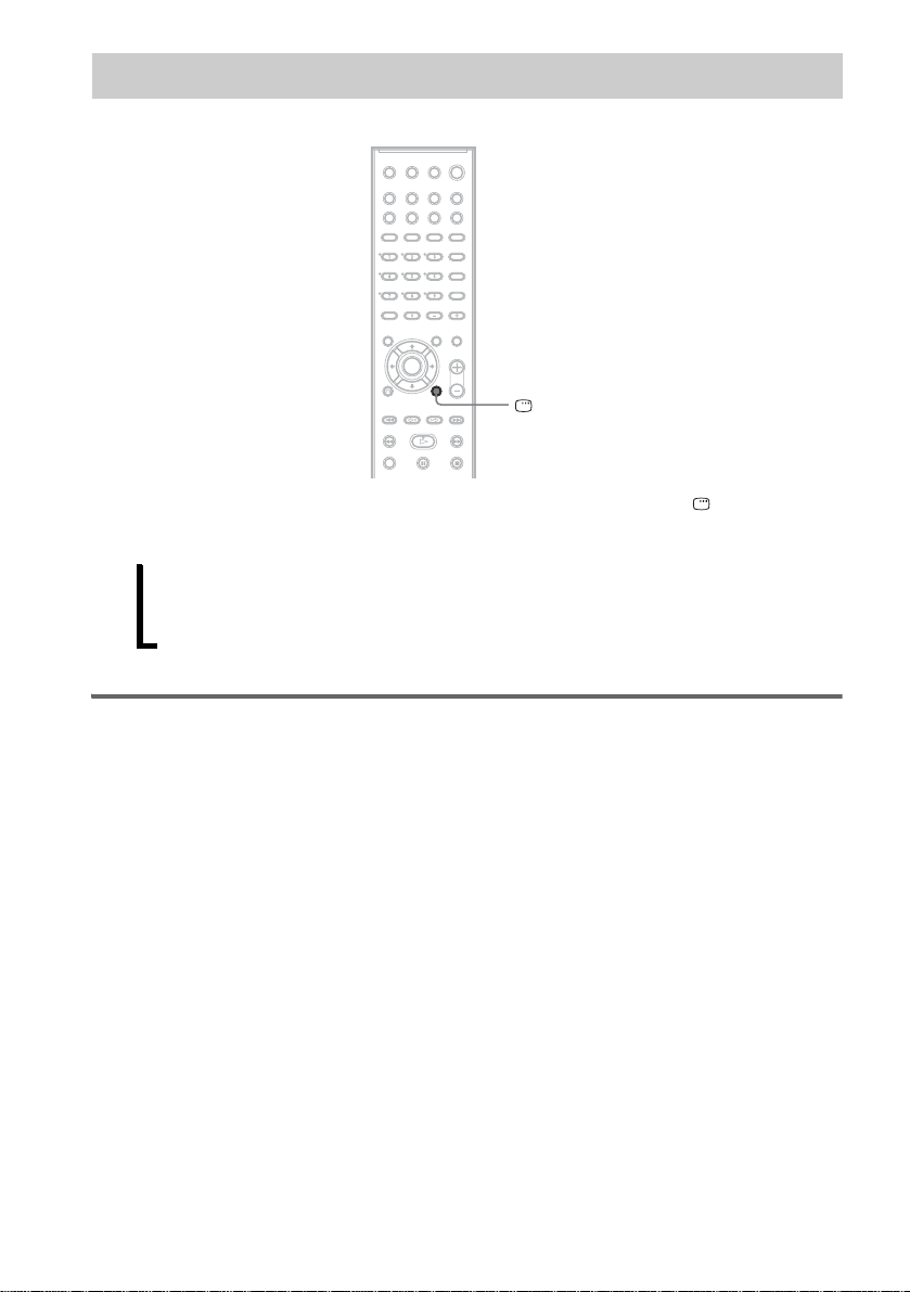
Guide to the Control Menu Display
DISPLAY
Use the Control Menu to select a function and to view related information. Press DISPLAY
repeatedly to turn on or change the Control Menu display as follows:
Control Menu display 1
,
m
Control Menu display 2 (appear s f or certa in discs only)
m
Control Menu display off
Control Menu display
The Control Menu display 1 and 2 will show different items depending on the disc type. For details
about each item, see the pages in parentheses.
GB
10
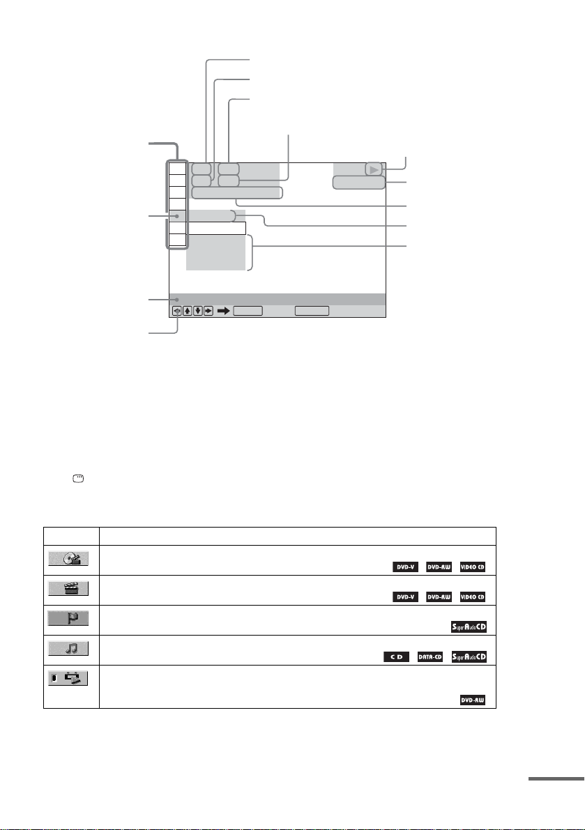
Example: Control Menu display 1 when playing a DVD VIDEO.
1
2
1
Playback status
2
(N Playback, X
Pause,
x Stop, etc.)
Type of disc being
3
played*
Playing time*
Current setting
Options
4
Control Menu items
Selected item
1 2 ( 2 7
1 8 ( 3 4
T
1 : 3 2 : 5 5
OFF
OFF
DISC
TITLE
Currently playing title number*
Currently playing ch apter number*
Total number of titles*
Total number of chapters*
)
)
DVD VIDEO
CHAPTER
Function name of
selected Control
Menu item
Operation message
REPEAT
ENTER DISPLAY
Quit:
*1Displays the scene number for VIDEO CDs (PBC is on), track number for VIDEO CDs/Super Audio CDs/CDs,
album number for DATA CDs. DivX video album number for DATA DVDs/DATA CDs.
*2Displays the index number for VIDEO CDs/ Su pe r Audio CDs, MP3 audio track number, or JPEG image file
number for DATA CDs. DivX video file number for DATA DVDs/DATA CDs.
*3Displays Super VCD as “SVCD.” Displays “MP3” in the Control Menu display 1 or “JPEG” in the Control Menu
2 for DATA CDs.
*4Displays the date for JPEG files.
To turn off the display
Press DISPLAY.
List of Control Menu items
Item Item Name, Function, Relevant Disc Type
[TITLE] (page 53)/[SCENE] (page 53)/[TRACK] (page 53)
Selects the title, scene, or track to be played.
[CHAPTER] (page 53)/[INDEX] (page 53)
Selects the chapter or index to be played.
[INDEX] (page 53)
Displays the index and selects the index to be played.
[TRACK] (page 53)
Selects the track to be played.
[ORIGINAL/PLAY LIST] (page 41)
Selects the type of titles (DVD-RW) to be played, the [ORIGINAL] one, or an edited [PLAY
LIST].
continued
11
GB
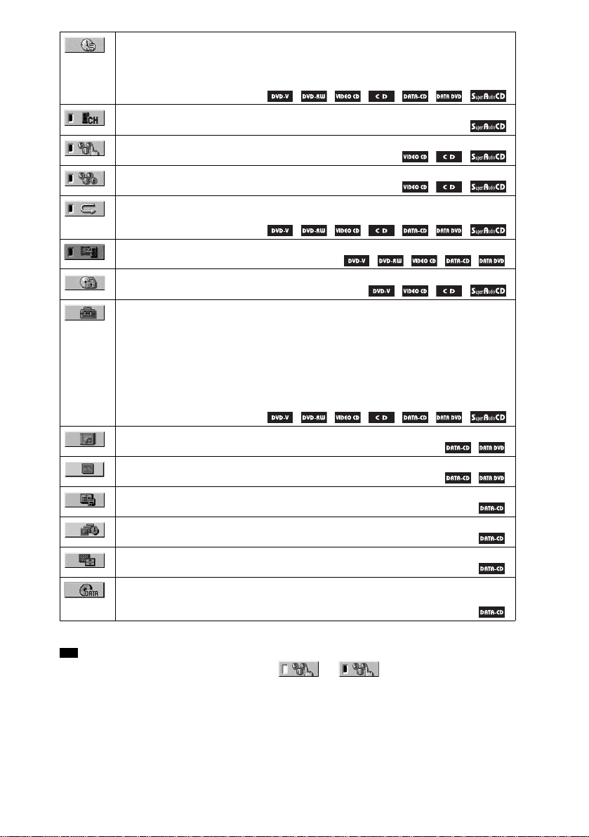
[TIME/TEXT] (page 54)
Checks the elapsed tim e and the remaining playback time.
Input the time code for picture and mus ic searching.
Displays the DVD/CD text or the MP3 track name.
[MULTI/2CH] (page 41)
Selects the playback area on Super Audio CDs when available.
[PROGRAM] (page 38)
Selects the track to play in the order yo u want .
[SHUFFLE] (page 39)
Plays the track in random or de r.
[REPEAT] (page 39)
Plays the entire disc (all titles/all tracks/all albums) repeatedly or one title/chapter/track/album
repeatedly.
[A/V SYNC] (page 51)
Adjusts the delay between the picture and so und.
[PARENTAL CONTROL] (page 67)
Sets to prohibit playback on this syst em.
[SETUP] (page 7 9)
[QUICK] Setup (page 33)
Use Quick Setup to choose the desired language of the on-screen display, the aspect ratio of
the TV, and the size of the speakers you are using.
[CUSTOM] Setup
In addition to the Quick Setup setting, you can a djust various other settings.
[RESET]
Returns the settings in [SETUP] to the default setting.
[ALBUM] (page 53)
Selects the album to be played.
[FILE] (page 53)
Selects the JPEG im age file or DivX video file to be playe d.
[DATE] (page 58)
*
Displays the date the picture was taken by a digit al came ra.
[INTERVAL] (page 48)
*
Specifies the duration for which the slides are displayed on the screen.
[EFFECT] (page 49)
*
Selects the effects to be used for changing slides during a slide show.
[MODE (MP3, JPEG)] (page 47)
*
Selects the data type; MP3 audio track (AUDIO), JPEG image file (IMAGE) or both
(AUTO) to be played when playing a DATA CD.
* These items are not displayed when playing a DATA CD with DivX video file.
Tip
• The Control Menu icon indicator lights up in green when you select any item except [OFF]
t
([PROGRAM], [SHUFFLE], [REPEAT], [A/V SYNC] only). The [ORIGINAL/P LAY LIS T] indica tor lights up
in green when you select [PLAY LIST] (default setting). The [MULTI/2CH] indicator lights up in green when you
select the multi-channel playba c k are a on a Super Audio CD.
12
GB
Getting Started
Unpacking
Check that you have the following items:
•Speakers (5)
• Subwoofer (1)
• Posts (long × 2, short × 2)
• Bases (2)
• Terminal cov ers (2)
• Screws (10)
• AM loop antenna (aerial) (1)
• FM wire antenna (a erial) (1)
• Speaker co rds (5 m × 4, 15 m × 2)
(16.5 ft. × 4, 49.5 ft . × 2)
• Video Cord (1)
• Remote Commander (remote) (1)
• Size AA (R6) batteries (2)
• Wall-mount pads
• Operating Instructions
• Speaker and TV connections (card) (1)
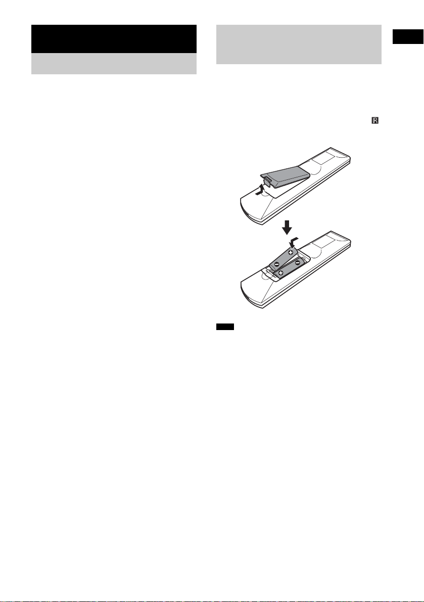
Inserting Batteries into
Getting Started
the Remote
You can control the system using the supplied
remote. Insert two Size AA (R6) batteries by
matching the 3 and # ends on the batteries to
the markings inside the compartment. When
using the remote, point it at the remote s ensor
on the system.
Note
• Do not leave the remote in an extremely hot or humid
place.
• Do not use a new battery with an old one.
• Do not drop any foreign object into the remote casing,
particularly when replac ing th e ba tteries.
• Do not expose the remote sensor to direct light from
the sun or lighting apparatus. Doi ng so ma y c au se a
malfunction.
• If you do not intend to use the remote for an extended
period of time, remove the batteries to avoid possible
damage from battery leakage and corros ion.
13
GB

Hookup Overview
Perform all connections and settings by following Steps 1 to 7.
“Step 1: Speaker System Hookup” (page 15)
“Step 2: Antenna (Aerial) Hookup” (page 24)
“Step 3: TV Hookup” (page 25)
“Step 4: Other Component Hookup” (page 30)
“Step 5: Connecting the AC Power Cord (Mains Lead)” (page 32)
“Step 6: Turning off the Demonstration” (page 32)
“Step 7: Performing the Quick Setup” (page 33)
Video signal is se nt to th e TV , and is output from the TV screen; audio signals are processed by th is
system and outpu t fro m the speakers of this system. You can also enjoy sound of other s our ces, such
as TV programs, in ad di tion to DVDs or CDs.
14
GB

Step 1: Speaker System Hookup
Connect the supplied speaker system using the supplied speaker cords by matching the colors of the
jacks to those of the cords. Do not connect any speakers other than those supplied with this system.
To obtain the best possible surround sound, specify the speaker parameters (distance, level, etc.) on
page 83.
Required cords
Speaker cords
The connector and the color tube of the speaker cor ds are the same colo r as the label of the jacks to be
connected.
Gray
(+)
(–)
Color tube
(+)
(–)
Black
Attaching the speaker stand to the speaker
(Front speakers only)
Before connecting the speakers, attach the speaker stand to the speaker.
Note
• Spread a cloth on the f loor to a void damaging the floor.
Tip
• You ca n u se th e speaker without the speaker stand by inst alling it on the wall (page 21).
1 Insert the post into the base.
Getting Started
continued
15
GB

The long post is for fl oor use, the short post is for tabletop use.
Post (long)
or
Screw holes
Base
2 Secure the base to the post by screws.
Post (short)
Bottom of the base
Screws (3)
3 Draw the speaker cord through the hole on the base, then stand it up.
Bottom of the
base
,
Speaker cord
GB
16

4 Draw the speaker cord through the hole on the speaker.
Hole
Speaker cord
Speaker
5 Mount the speaker on the post.
Getting Started
Speaker
,
,
Note
• Do not catch the speaker cord between the speaker and the post.
• Do not drop the speaker when mounting.
continued
17
GB
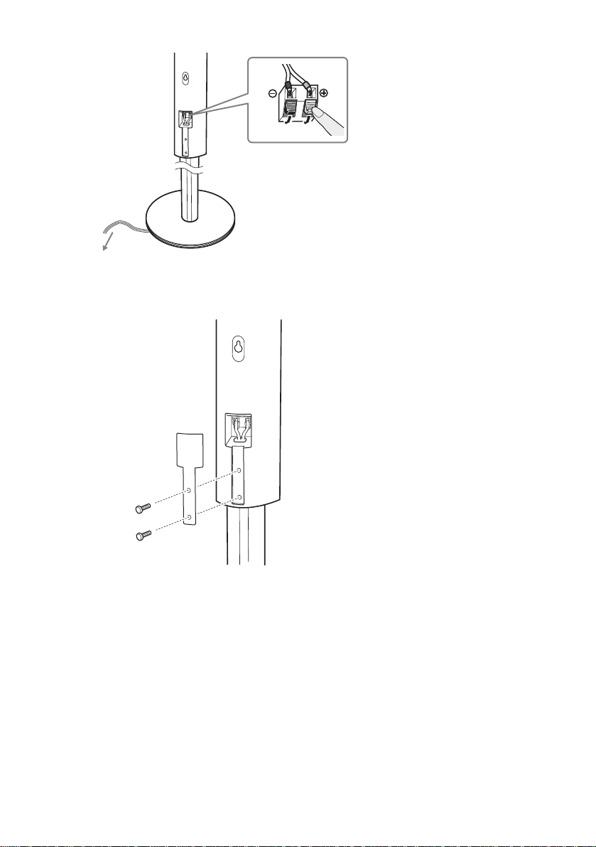
6 Connect the speaker cord to the speaker, then adjust the length of the speaker cord.
Adjust the length of the speaker cord.
7 Attach the terminal cover to the speaker by screws.
Terminal cover
18
Screws (2)
GB
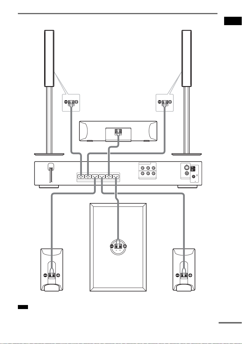
Connecting the speakers
Front speaker (R)
Getting Started
Front speaker (L)
Rear side of the front
speaker
FRONT R FRONT L SURR R SURR L CENTER WOOFER
SPEAKER
Center speaker
Rear side of the front
speaker
DVD ONLY
COMPONENT VIDEO OUT
Y
PB/CBPR/C
R
R AUDIO IN VIDEO INL
VIDEO/SAT
S VIDEO(DVD ONLY)
VIDEO
MONITOR OUT
COAXIAL
FM
AM
75
Surround speaker (R)
Note
• Do not set the speakers in an inclined position.
Subwoofer
Surround speaker (L)
continued
19
GB
• Do not place the speakers in locations that are:
– Extremely hot or cold
– Dusty or dirty
– Very humid
– Subject to vibrations
– Subject to direct sunlight
• Use caution when placing the speakers and/or speaker stands (not supplied) that are attached with the speakers on
a specially treated (waxed, oile d, pol ished, etc.) floor, as staining or discoloration may result.
• When cleaning, use a soft cloth such as a cleaning cloth for glasses.
• Do not use any type of abrasive pad, scouring powder, or solvent such as alcohol or be nz ine .
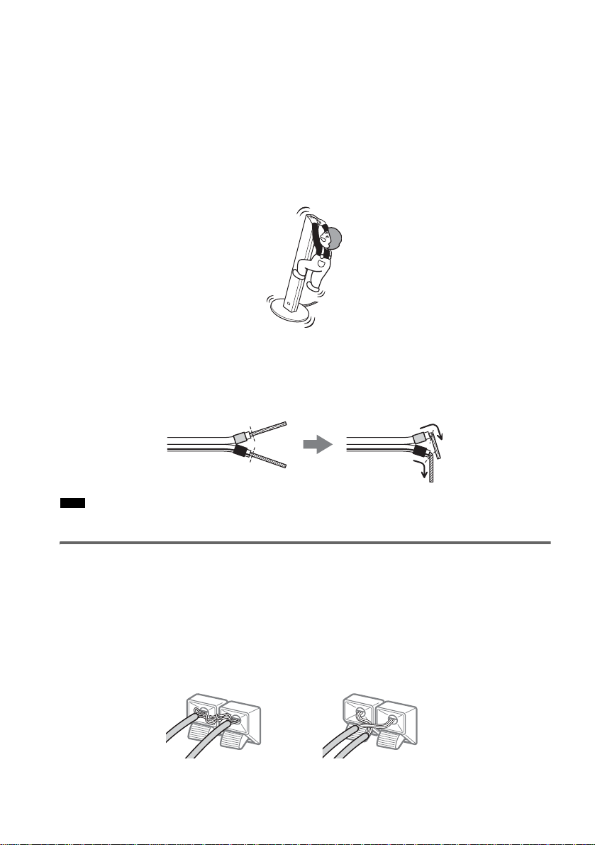
• Do n ot le a n or hang on the speaker, as the speaker may fall down.
To connect the speaker cords
Connect the speaker cords after bending the bare wire at the end of the insulation. This prevents the
speaker i n sulation from being inserted in the speaker terminal.
Note
• D o no t c atch the speaker cord insulation in the SPEAKER jack.
Avoiding short-circuiting the speakers
Short-circuiting of the speakers may damage the system. To prevent this, be sure to follow these
precautions w hen conne cting the speakers. Ma ke sure th e bare wire of each spea ker cord do es not tou ch
another speaker terminal or the bare wire of an other speaker cord.
Examples of poor conditions of the speaker cord
Stripped cords are touching each
other due to excessive removal of
insulation.
20
Stripped speaker cord is
touching another speaker
terminal.
GB
After connecting all the components, speakers , an d AC power cord (mains lea d) , output a te st to ne to
check that all the speakers are connected correc tl y. For details on outputting a tes t to ne, see page 85.
If no sound is heard from a speaker while ou t putting a t est tone, or a test t one is output from a speaker
other than the one curr ently disp layed on the Setup Di splay, t he sp eaker may b e short -circ uite d. If this
happens, check the speaker connection again.
Note
• Be sure to match the speaker cord to the appropriate terminal on the components: 3 to 3, and # to #. If t he cords
are reversed, the sound will lack ba ss an d ma y be distorted.
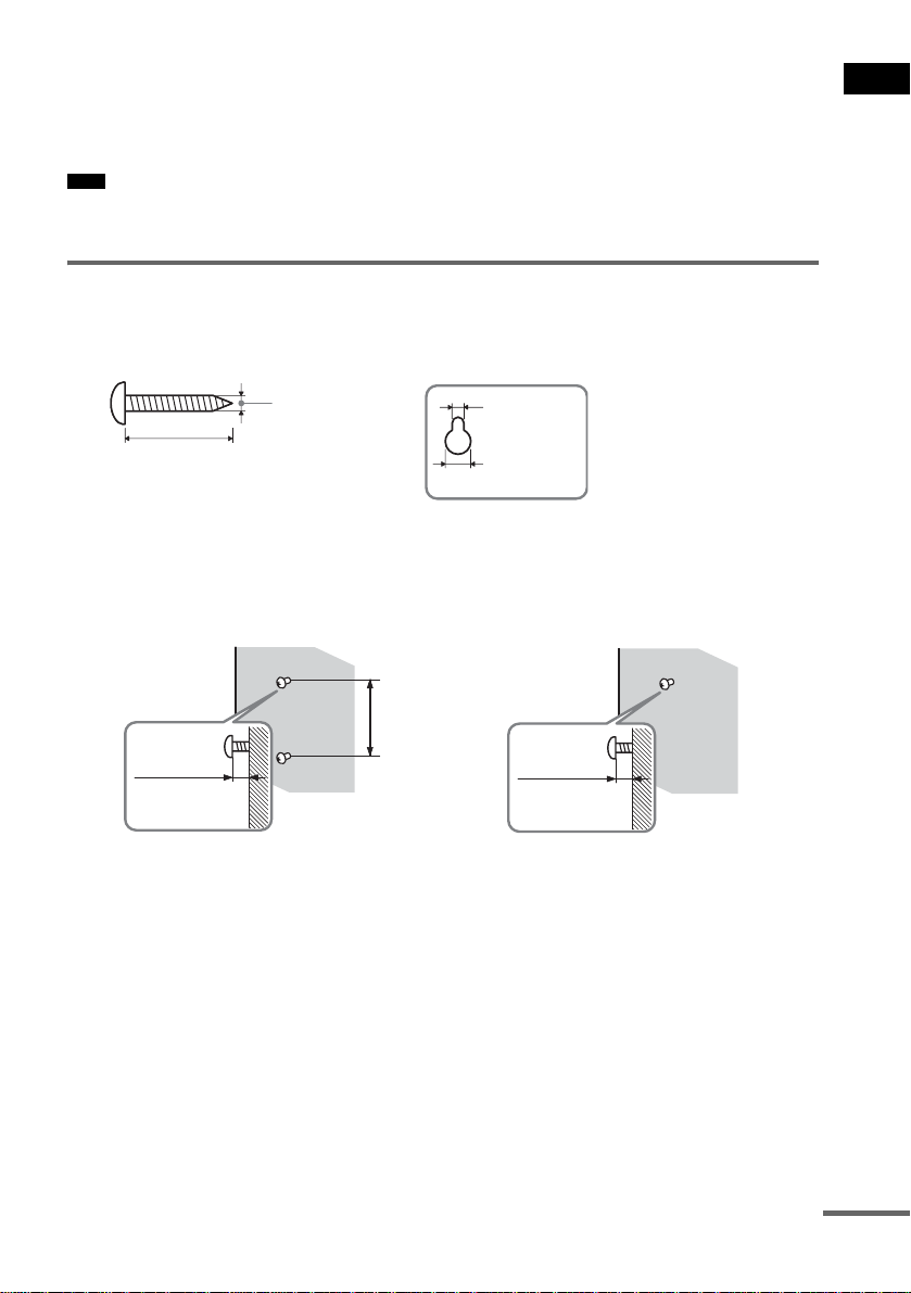
Installing the speakers on the wall
1 Prepare screws (not supplied) that are suitable for the hole on the back of each speaker.
See the illustrations be low.
Getting Started
Hole on the back of
the speaker
25 mm (1 inch)
4 mm (
5
/32 inch)
4.6 mm
3
/16 inch)
(
10 mm
13
(
/32 inch)
2 Fasten the screws to the wall.
The screws should protrude 7 to 8 mm (9/32 to 11/32 inch) for the front speakers, 8 to 9
mm (11/32 to 3/8 inch) for the surround speakers.
For the front speakers
7 to 8 mm
9
(
/32 to 11/32 inch)
165 mm
1
(6
/2 inch)
For the surround speakers
8 to 9 mm
11
/32 to 3/8 inch)
(
3 Peel the seals off the two screw points on the rear of the speaker.
(Front speakers only)
continued
21
GB
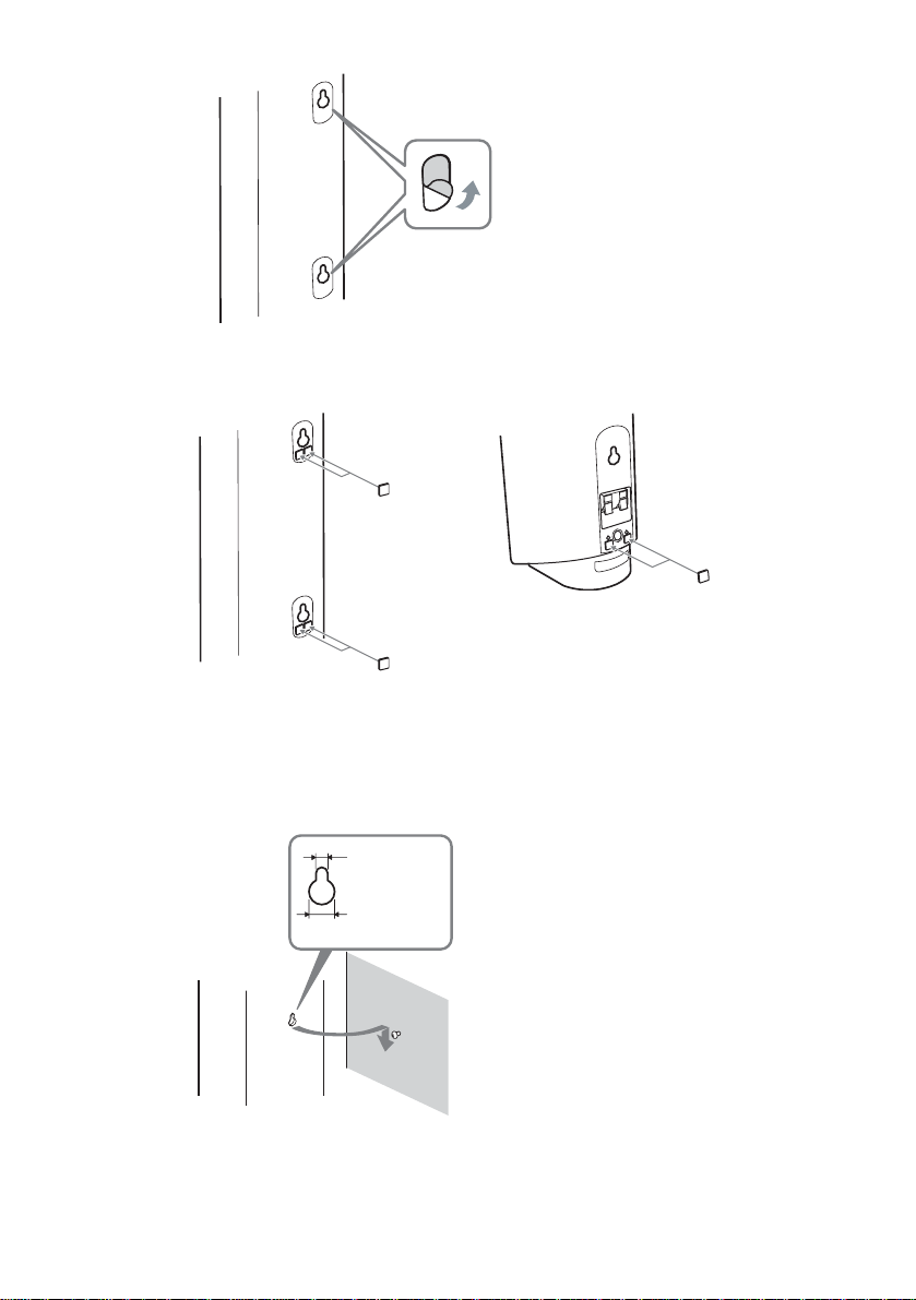
4 Attach the wall-mount pads on the rear side of the speaker.
Front speaker
Wall-mount pads
(7 × 7 mm, 3 mm thick)
9
/32 × 9/32 inch, 1/8 inch thick)
(
Surround speaker
Wall-mount pads
(7 × 7 mm, 3 mm thick)
9
(
/32 × 9/32 inch, 1/8 inch thick)
5 Hang the speakers on the screws.
22
4.6 mm
3
/16 inch)
(
10 mm
13
(
/32 inch)
GB
Hole on the back of
the speaker

Note
• Use screws that are suitable for the wall material and strength. As a plaster board wall is especially fragile, attach
the screws securely to a beam and fasten them to the wa ll . In st al l the speak ers on a vertical and flat wall where
reinforcement is applied.
• Contact a screw shop or installer regarding the wall material or screws to be used.
• Sony is not responsible for accident or damage caused by imprope r insta llation, insufficient wall strength or
improper screw insta lla tion, natural calamity, etc.
Getting Started
23
GB
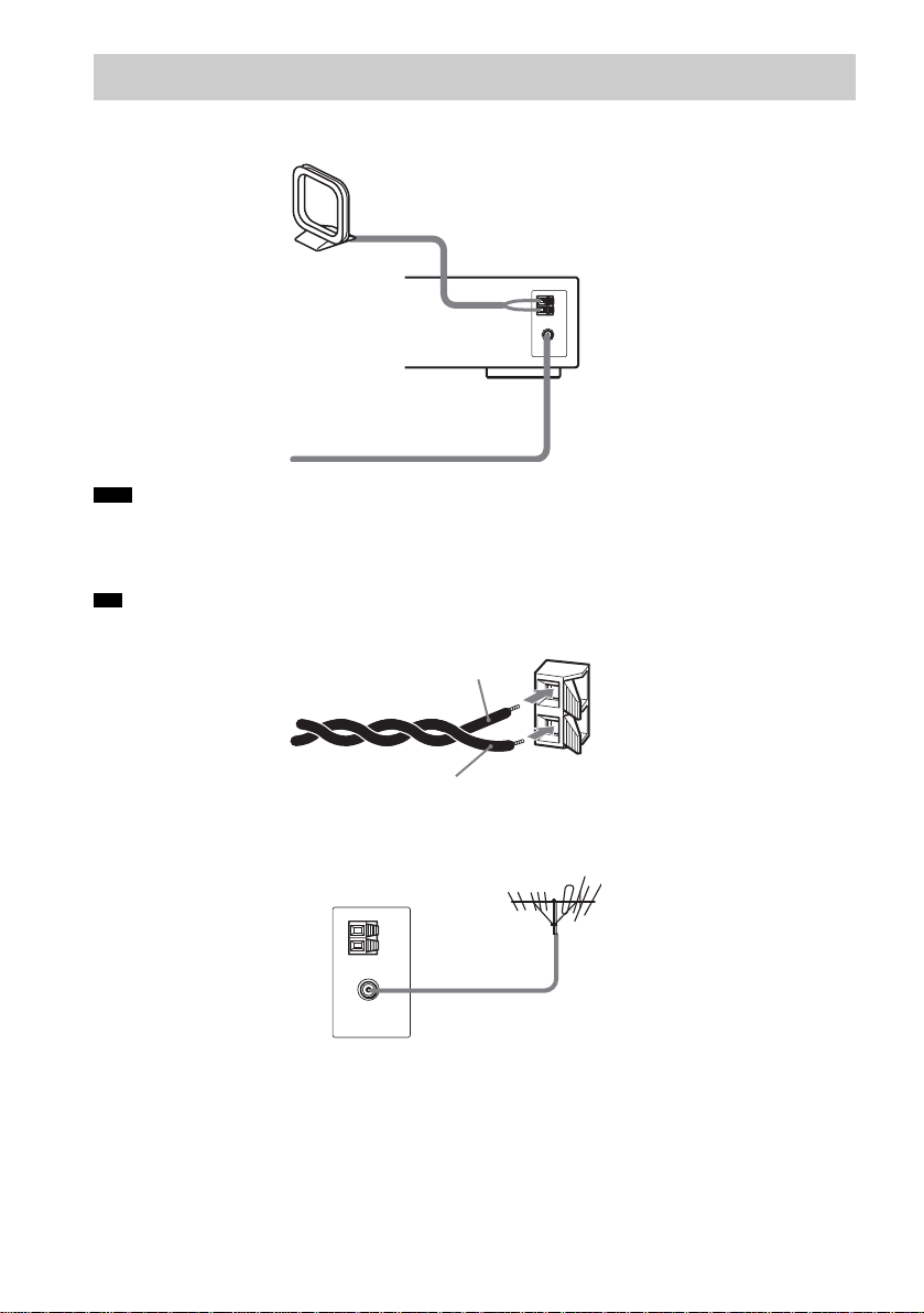
Step 2: Antenna (Aerial) Hookup
Connect the supplied AM/FM antennas (aerials) for listening to the radio.
AM loop antenna (aerial)
FM wire antenna (aerial)
Note
• To prevent noise pickup, keep the AM loop antenna (aerial) away from the system and other components.
• Be sure to fully extend the FM wire ant enn a (aerial).
• After connecting the FM wire antenna (aerial), keep it as horizontal as possible.
Tip
• When you connect the supplied AM loop antenna (aerial), cord (A) or cord (B) can be connected to either terminal.
A
B
• If you have poor FM reception, use a 75-ohms coaxial cable (not supplied) to connect the system to an outdoor FM
antenna (aerial) as shown below .
System
Outdoor FM antenna (aerial)
GB
24
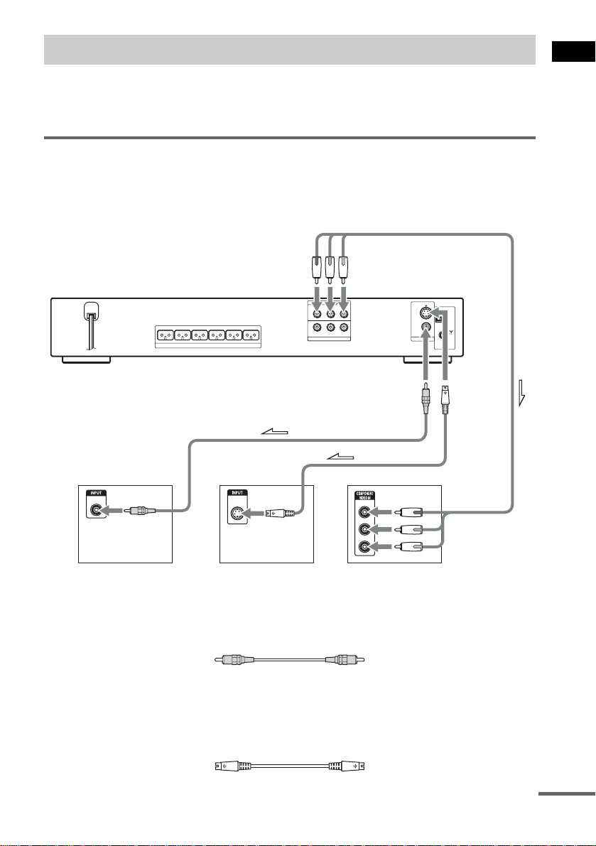
Step 3: TV Hookup
First, perform the vi deo connection, and then audio connection.
With your TV’s audio output connected to this system, you can listen to TV sound through the system
speakers.
Connecting the video cords
Sends a played back DVD image to a TV.
Check the jacks of your TV, and choose the A, B or C connection. Picture quality improves in order
from A (stand ar d) to C (component).
To COMPONENT
VIDEO OUT
DVD ONLY
FRONT R FRONT L SURR R SURR L CENTER WOOFER
SPEAKER
COMPONENT VIDEO OUT
Y
PB/CBPR/C
R AUDIO IN VIDEO INL
VIDEO/SAT
R
S VIDEO(DVD ONLY)
VIDEO
MONITOR OUT
COAXIAL
FM
AM
75
Getting Started
To VIDEO
To
S VIDEO
AB C
VIDEO
IN
TV TV with S VIDEO IN jack
A To connect to a TV with the VIDEO IN jacks
Connect the video co rd.
B To connect to a TV with the S VIDEO IN jack
Connect an S video cor d (not supplied). When using the S vi deo jack instead of the video jacks, your
TV monitor must also be connected via an S video jack. S video signals are on a separate bus from the
video signals and wi l l not be output through the video jacks.
S VIDEO
IN
Y
PB/CB
PR/CR
TV with COMPONENT
VIDEO IN jacks
Yellow
continued
25
GB
C To connect to a TV with the COMPONENT VIDEO IN jacks
Connect a co mponent vi deo co rd (not supp lie d). T o use th e COMP ONENT VIDEO O UT jac ks (Y, P B/
B, PR/CR) instead of the video jacks, your TV monitor must be equipped with via COMPONENT
C
VIDEO IN jacks (Y, P
connection and set the output channel of the sy st em to progressive format (page 26).
B/CB, PR/CR). If your TV accepts progressive format signals, you must use this
Green
Blue
Red
When connecting to a standard 4:3 screen TV
Depending on the di sc, the image may not fit your TV scr een.
To change the aspect ratio, see page 81.
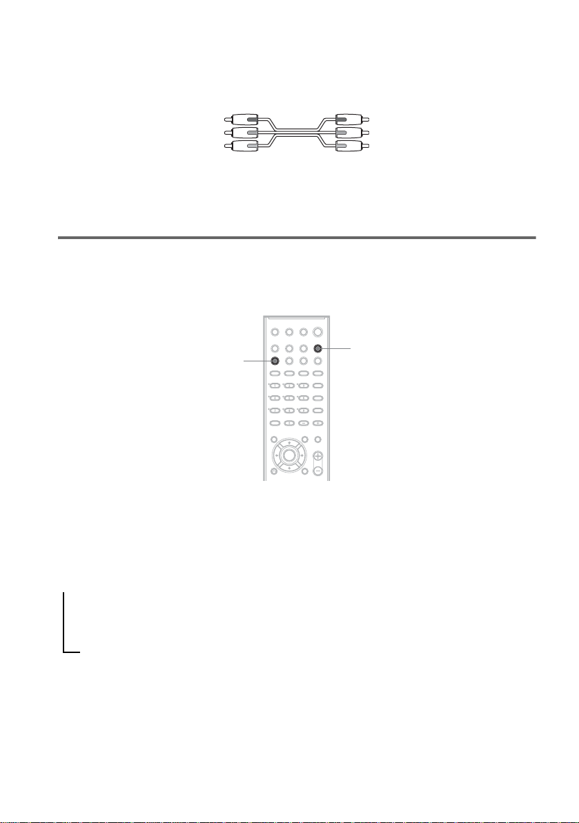
Does your TV accept progressive signals?
Progressive is the method for displaying TV images which reduces flickering, and sharpens the image.
To display using thi s m e thod, you need to connect to a TV that a ccepts progressive signals.
PROGRESSIVE
“P AUTO” or “P VIDEO” appears in the front panel display when the system outputs progressive
signals.
FUNCTION
1 Press FUNCTION repeatedly to select “DVD.”
2 Press PROGRESSIVE.
Each time you press PROGRESSIVE, the display changes as follows:
t P AUTO (PROGRESSIVE AUTO)
r
P VIDEO (PROGRESSIVE VIDEO)
r
INTERLACE
x P AUTO (PRO G R ES SI VE A U T O )
Select this setting when:
– your TV accepts progressive signals, and,
– the TV is connected to the COMPONENT VIDEO OUT jacks.
Normally select this under the above condition. This automaticall y detects the software type, and
selects the appropriate conversion method .
26
GB

Note that the picture will not be clear or no picture will appear if you select these settings when
either of the above conditions is not met.
x P VIDEO (PROGRESSIVE VIDEO)
Select this setting when:
– your TV accepts progressive signals, and,
– the TV is connected to the COMPONENT VIDEO OUT jacks, and,
– you want to fix the conversion method to PROGRESSIVE VIDEO for video- based software.
Select this if the image is not clear when you select PROGRESSIVE AUTO.
Note that the picture will not be clear or no picture will appear if you select these settings when
either of the above conditions is not met.
x INTERLACE
Select this setting when:
– your TV does not ac cept progressive signals, or,
– your TV is connected to jacks other than the COMPONENT VIDEO OUT jacks (MONITOR
OUT (VIDEO/S VIDEO)).
About DVD software types and the conversion method
DVD software can be divided into 2 types: film-based software and video-based software.
Video-based software is derived from TV, such as dramas and sit-coms, and displays images at 30
frames/60 f ields per s econd. Fi lm-based software is derived f rom film an d display s images at 24 frames
per second. Some DVD software contains both video and film.
In order for these i mages to appear natural on your screen when output in progressive format, the
progressive signal s need to be converted to match the t ype of DVD software that you are wa tc hi ng.
Note
• When you pl ay video-based software in progressive signal format, secti ons of some types of images may appear
unnatural due to the conversion process when output through the COMPONENT VIDEO OUT jacks. Even though
you set to “PROGRESSIVE AUTO” or “PROGRESSIVE VIDEO,” images from the MONITOR OUT (VIDEO or
S VIDEO) jack are unaffected as they are output in th e in t e rl ace format.
Getting Started
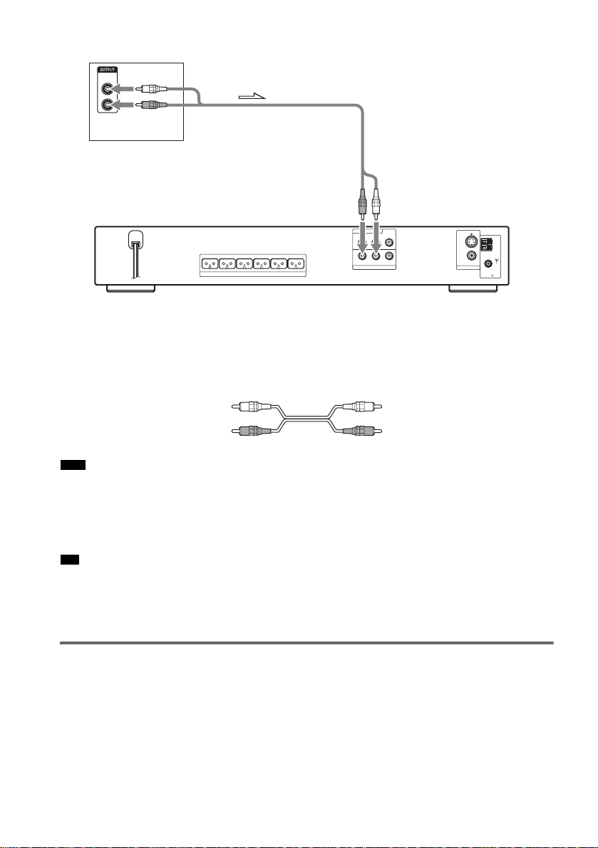
Connecting the audio cords
Outputs TV sound through the speakers of this sys tem.
continued
27
GB
TV
AUDIO
OUT
L
R
To VIDEO/SAT
(AUDIO IN)
DVD ONLY
FRONT R FRONT L SURR R SURR L CENTER WOOFER
SPEAKER
COMPONENT VIDEO OUT
Y
PB/CBPR/C
R AUDIO IN VIDEO INL
VIDEO/SAT
R
S VIDEO(DVD ONLY)
VIDEO
MONITOR OUT
COAXIAL
FM
AM
75
To connect the AUDIO OUT jacks of a TV to the VIDEO/SAT (AUDIO IN)
jacks of this system
Connect a TV to the VIDEO/SAT (AUDIO IN) jacks using an audio cord (not supplied). When
connecting a cord, be sure to match the color-coded sleeves to the appropriate jacks on the components.
White (L/audio)
Red (R/audio)
Note
• Be sur e to ma ke conn ec ti ons se c ur el y to a void hum and noise. If using the VIDEO/SAT jacks distorts the so und,
change the attenuat e se tt ing (page 74 ) .
• If your TV does not have AUDIO OUT jacks, you c annot out put the TV sound fro m the spea kers of this system.
• If you connect a TV to the VIDEO/SAT (AUDIO IN) jacks, other components, such as a VCR, cannot be
connected.
Tip
• To listen to the TV sound, select the function by pressing FUNCTION. For details, see pa ge 64 .
• When you want to output the TV sound or stereo sound of a 2 channel source from the 6 speakers, select the “Dolby
Pro Logic,” “Dolby Pro Logic II MOVIE,” or “Dolby Pro Logic II MUSIC ” sound f ield ( page 62).
• Wh en you se le ct the “NIGHT” sound field (page 62) , th e sound is output from the front speakers only.
To change the color system (PAL or NTSC)
(Asian, Australian, and Middle Eastern models only)
Depending on the T V to be connected, you may be required to s el ec t e it he r PAL or NTSC of the
system.
The initial setting of the system for Australian and Middle Eastern models is PAL.
The initial setting of the system for Asian models is NTSC.
GB
28

If the color system of the TV is PAL
To set the system to PAL from NTSC, turn on the system by pressing "/1 while pressing X on the
system.
You need to hold X until the set powers on.
To reset to NTSC, turn of f th e system and then turn on again by p ressing "/1 while pressing and
holding X on the system.
If the color system of the TV is NTSC
Do the same operation above to set the system to NTSC from PAL.
Getting Started
29
GB
Step 4: Other Component Hookup
You can enjoy sound using the speakers of this system by connecting the AUDIO OUT jacks of another
component. For video connection of other components, connect directly to the TV.
Note
• If you conne c t a TV to the VIDEO/SAT jacks in Step 3 (page 25), you cannot connect other components to the
system.
Connecting the system and the other component
Outputs the other component through the system .
VCR, digital satellite receiver,
or PlayStation 2, etc .
VIDEO
OUT
AUDIO
OUT
L
R
To VIDEO/SAT
(VIDEO/AUDIO IN)
DVD ONLY
FRONT R FRONT L SURR R SURR L CENTER WOOFER
SPEAKER
COMPONENT VIDEO OUT
Y
PB/CBPR/C
R AUDIO IN VIDEO INL
VIDEO/SAT
R
S VIDEO(DVD ONLY)
VIDEO
MONITOR OUT
COAXIAL
FM
AM
75
To connect the VIDEO/AUDIO OUT jacks of other component to the
VIDEO/SAT (VIDEO/AUDIO IN) jacks of this system
Connect the VCR or other components to the VIDEO/SAT (VIDEO/AUDIO IN) jacks using the video/
audio cord (not supplied). When connectin g a cord, be sure to match the color-coded sleeves to the
appropriate jacks on the components.
Yellow (Video)
White (L/audio)
Red (R/audio)
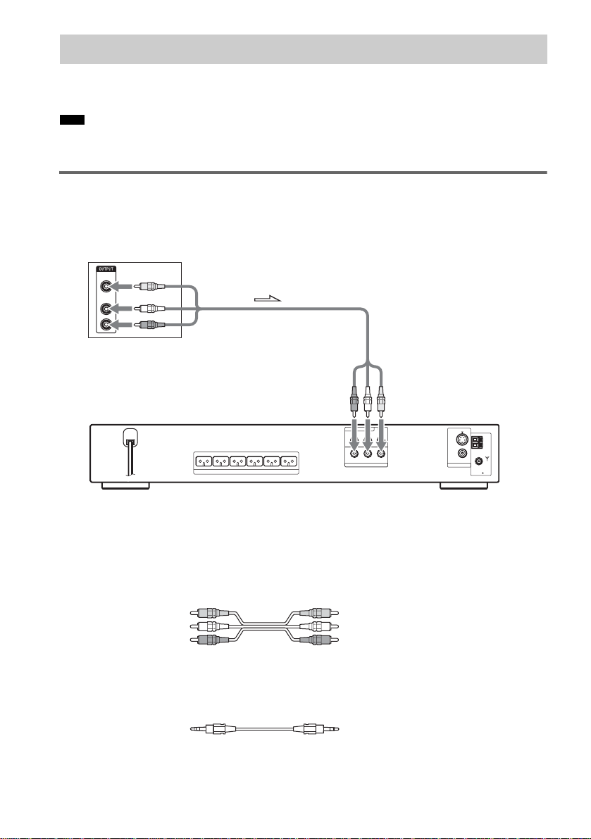
To listen to the portable audio source sound through the system
Connect the audio output jacks of the portable audio source to the AUDIO IN jack on the front panel
of the system with the stereo mini-plug cord (not supplied).
GB
30
 Loading...