

Sony DAV-DC150, DAV-BC250 Operating Instructions Manual
2-102-802-13(1)
DVD Home Theatre
System
Operating Instructions
DAV-BC150/BC250
©2004 Sony Corporation
3
WARNING
To prevent fire or shock hazard, do not
expose the unit to rain or mo ist u r e.
Caution – The use of optical instruments
with this product will increase eye
hazard.
For the customers in the U.S.A
This symbol is int ended to alert the us er to
the presence of uninsulated “d an ge ro u s
voltage” within the p ro du ct ’ s e n clo s u r e th at
may be of sufficient magnitude to constitute a risk of
electric shock to persons.
This symbol is int ended to alert the us er to
the presence of important operating and
maintenance (servicing) instructions in the
literature accompanying the ap pliance.
Owner’s Record
The model and seri al numbers are l ocated at t he rear of
the unit. Record the serial numb er in the space
provided below. Refer to them whenever you call upon
your Sony dealer regarding this product.
Model No. DAV-BC150/BC250
Serial No.______________
WARNING
This equipment has been tested and fou nd to co mply
with the limits for a Class B digital device, pursuant to
Part 15 of the FCC Rules. These limits are designed to
provide reasonable protection a gai nst harmful
interference in a residential installat ion. This
equipment generates, uses, and c an ra dia te radi o
frequency energy and, if not installed and used in
accordance with the instruc tions, may cause harmful
interference to radio commu nicati ons. However , ther e
is no guarantee that interference will not occur in a
particular installation. If thi s eq uipment does cause
harmful interference to radio or television reception,
which can be determined by turning the equipment off
and on, the user is encouraged to try to correct the
interference by one or more of the following measures:
– Reorient or relocate the rec eiving antenna.
– Increase the separation between the equipment and
receiver.
– Connect the equipment into an outlet on a circuit
different from that to which the receiver is
connected.
– Consult the dealer or an experienced radio/TV
technician for help.
CAUTION
You are cautioned that any changes or modif icat ions
not expressly approved in this manual could void your
authority to operate this equipm ent .
Note to CATV system installer:
This reminder is provided to call the CATV sys tem
installer’s attention to Article 820-40 o f th e N E C that
provides guidelines for proper ground ing a nd, in
particular, specifies that the cable ground shall be
connected to the grounding system of the building, as
close to the point of cable entry as practical.
For the customers in Canada
CAUTION
TO PREVENT ELECTRIC SHOCK, MATCH WIDE
BLADE OF PLUG TO WIDE SLOT, FULLY
INSERT.
Except for North American
models
Do not install the appliance in a confined space, such
as a bookcase or built-in cabinet.
To prevent fire, do not cover the ventilation of the
apparatus with news papers, table-cloths, curtains, etc.
And don’t place lighted candles on the app ara tus.
To prevent fire or shock hazard, do not place objects
filled with liquids, such as vases, on the apparatus.
Don’t throw away the batter y with
general house waste, dispose of it
correctly as chemical waste.
This appliance is
classified as a CLASS 1
LASER product. This
marking is located on the
rear of the unit.
US
2

Precautions
Safety
• If anything falls into the cabinet, unplug the unit and
have it checked by qualified personnel be f ore
operating it any further.
• The unit is not disconnected from the AC power
source (mains) as long as it is connected to the wall
outlet, even if the unit itse lf ha s been turned off.
• Unplug the unit from the wall outlet if you do not
intend to use it for an extended per iod of time. To
disconnect the cord, pull it out by the plug, nev er by
the cord.
Installing
• Allow adeq u ate air circula tion to prevent in ternal
heat buildup.
• Do not place the uni t on surfaces (r ugs, blanket s, etc.)
or near materials (curtains, draperies) that may block
the ventilation slots.
• Do not install the unit near heat sources such as
radiators, or air ducts, or in a place subject to di rec t
sunlight, excessive dust, mechanical vibration, or
shock.
• Do not install the unit in an incline d position. It is
designed to be operated in a horizontal position only.
• Keep the unit and discs away from equipment with
strong magnets, such as microwave ove ns, or large
loudspeakers.
• Do not place heavy objects on the unit.
• If the unit is brought directly from a cold to a warm
location, moisture may condense inside the DVD
Home Theatre System and cause damage to the
lenses. When you first install the unit, or when you
move it from a cold to a warm location, wait for about
30 minutes before operating th e unit.
®
ENERGY STAR
registered mark.
As an ENERGY STAR
Sony Corporation has determined
that this product meets the
ENERGY STAR
energy efficiency.
is a U.S.
®
partner,
®
guidelines for
Welcome!
Thank you for purchasing Sony DVD Home
Theatre System . B ef ore operating this sys te m,
please read this manual thoro ughly and retain it
for future reference.
Precautions
On power sources
AC power cord must be changed only at the qual ifie d
service shop.
On placement
• Place the s y stem in a locatio n w ith adequate
ventilation to prevent heat build-up in the system.
• At high volume, over long periods of time, the cabinet
becomes hot to the touch. This is not a malfunction.
However, touching the cabinet should be avoided. Do
not place the unit in a confined space where
ventilation is poor as this may cause overheating.
• Do not block the ventilation slots by putting anything
on the system. The system is equipped with a high
power amplifier. If the ventilation slots are blocked,
the unit can overheat and malfunction.
• Do not place the system on a s oft surface such as a rug
that might block the ventilation holes on the bottom.
• Do not place the system in a location ne ar he at
sources, or in a place subject to direct sunlight,
excessive dust, or mechanical shoc k.
On operation
• If the system is brought directly from a cold to a warm
location, or is placed in a very damp room, moisture
may condense on the l enses inside t he system. Shoul d
this occur, the system may not operate properly. In
this case, remove the dis c and leave the system turned
on for about half an hour until the moisture
evaporates.
• When you move the system, take out any disc. If you
don’t, the disc may be damaged.
On adjusting volume
Do not turn up the volume while listening to a section
with very low level inputs or no audio signa ls. If you
do, the speakers may be damaged when a peak level
section is suddenly played.
continued
US
3

On cleaning
Clean the cabinet, p anel, and co ntrol s with a s oft cloth
slightly moistened with a mild detergent solution. Do
not use any type of abrasive pad, scouring powder or
solvent such as alcohol or benzine .
If you have any questions or problems concerning your
system, please consult your nearest Sony dealer.
On cleaning discs
Do not use a commercially available CD/DVD
cleaning disc. It may cause a malfunction.
On your TV’s color
If the speakers should cause the TV screen to have
color irregularit y, tu rn o ff the T V at on ce the n tur n it
on after 15 to 30 minutes. If color irregularity should
persist, place the speakers farther away from the set.
The nameplate is located on the rear of the unit.
IMPORTANT NOTICE
Caution: This system is capable of holding a still
video image or on-screen displa y image on your
television screen indefinitely. If you leave the still
video image or on-screen displa y image displayed
on your TV for an extended period of time you risk
permanent damage to your television screen.
Projection televisions are especially susceptible to
this.
On moving the system
When you carry the system, use the following
procedure to protect the inner mechanism.
1 Press FUNCTION repeatedly to select
“DVD.”
2 Make sure that all discs are removed from
the system and that the disc tray is closed.
3 Press ., >, and DISC 1 A
simultaneously.
The front panel display is changed to
“MECH LOCK.”
4 Remove the AC power cord from the wall
outlet.
US
4

Table of Contents
Welcome!................................................3
Precautions..............................................3
About this Manual...................................7
This System Can Play the Following
Discs .................................................7
Terms for discs........................................7
Notes about the Discs..............................9
Note on DVD 5-DISC Changer............10
Guide to the Control Menu Display......11
Getting Started
Unpacking.............................................13
Inserting Batteries into the Remote.......13
Step 1: Speaker System Hookup...........14
Step 2: Antenna Hookups .....................19
Step 3: TV and Audio Component
Hookups..........................................20
Step 4: Connecting the AC
Power Cord.................................... .23
Speaker Setup........................................24
Playing Discs
Playing Discs ........................................28
Resuming Playback from the Point Where
You Stopped the Disc.....................30
(Resume Play)
Using the DVD’s Menu........................31
Playing VIDEO CDs with PBC Functions
(Ver.2.0)..........................................32
(PBC Playback)
About MP3 Audio Tracks and JPEG
Image Files .....................................33
Playing DATA CDs with MP3 Audio
Track and JPEG Image Files ..........34
Specifying the slideshow duration........38
Selecting an effect for image files in the
slideshow........................................39
Playing repeatedly.................................40
(Repeat Play)
Searching for a Particular Point on a
Disc.................................................41
(Scan, Slow-motion Play)
Searching for a Title/Chapter/Track/
Scene, etc........................................43
Viewing Information in the Front Panel
Display ........................................... 44
Sound Adjustments
Changing the Sound..............................50
Enjoying Surround Sound ....................51
Using the Sound Effect......................... 54
Using Various Additional
Functions
Changing the Angles............................ 55
Displaying the Subtitles...................... ..55
Locking Discs .......................................56
(CUSTOM PARENTAL
CONTROL, PARENTAL
CONTROL)
Other Operat io n s
Controlling the TV with the Supplied
Remote ........................................... 61
Using the SONY TV DIRECT
Function..........................................62
Using the Video or Other Unit ............. 63
Enjoying the Radio............................... 65
Using the Sleep Timer.......................... 67
Changing the Brightness of the Front
Panel Display..................................68
Returning to the Default Settings ......... 68
Settings and Adjustments
Using the Setup Display .......................69
Setting the Display or Sound Track
Language........................................ 70
(LANGUAGE SETUP)
Settings for the Display........................71
(SCREEN SETUP)
Custom Settings.................................... 72
(CUSTOM SETUP)
continued
US
5

Additional Information
Troubleshooting....................................74
Self-diagnosis Function ........................77
(When letters/numbers appear in
the display)
Specifications........................................77
Glossary................................................79
Index to Parts and Controls...................82
Language Code List..............................86
DVD Setup Menu List..........................87
AMP Menu List....................................88
Index ..................................................... 89
Quick reference for Remote Commander
.................................................Back cover
US
6
About this Manual
• The instructions in this manual describe the
controls on the remote. You can also use the
controls on the system if they have the same or
similar names as those on the remote.
• The following symbols are used in this
manual.
Format of
discs
CD-R/CD-RW
(audio data)
(MP3 files)
(JPEG files)
Disc logo
Symbol Meaning
Functions available for DVD
VIDEOs, DVD-Rs/DVD-RWs in
video mode and DVD+Rs/
DVD+RWs
Functions avai la ble in VIDEO CD
mode
Functions avai la ble in CD mode
Functions available for MP3* audio
tracks
Functions avai la ble for JPEG files
* MP3 (MPEG1 Audio Layer 3) is a standard format
defined by ISO/MPEG which compresses audio
data.
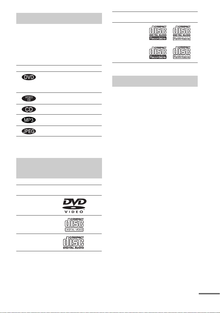
This System Can Play the Following Discs
Format of
discs
DVD VIDEO
VIDEO CD
Audio CD
Disc logo
The “DVD VIDEO” logo is a trademark.
Terms for discs
• Title
The longest section of a picture or music
feature on a DVD, movie, etc., in video
software, or the entire album in audio
software.
• Chapter
Section of a picture or a music piece that is
smaller than titles. A title is composed of
several chapters . Depending on the di sc, no
chapters may be record ed.
• Album
Section of a music piece or an image on a data
CD containing MP3 au di o t ra cks or JPEG
files.
• Track
Section of a picture or a m usic piece on a
VIDEO CD, CD, or MP3.
• Video Index (VIDE O C D)
A number that divides a track into sections to
easily locate the point you want on a VIDEO
CD. Depending on the disc, no indexes may be
recorded.
• Scene
On a VIDEO CD with PBC functions
(page 32), the menu sc reens, moving pict ures
and still pictures ar e di vided into sections
called “sce nes.”
• File
Section of a picture on a da ta C D containing
JPEG image files.
continued
US
7
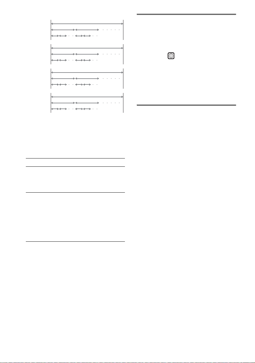
Disc
DVD
structure
VIDEO
CD, or CD
structure
MP3
structure
JPEG
structure
Title
Chapter
Track
Index
Album
Track
Album
File
Disc
Disc
Disc
Note on PBC (Playback Control)
(VIDEO CDs)
This system conforms to Ver. 1.1 and Ver. 2.0 of
VIDEO CD standards. You can en joy two ki nds
of playback depending on the disc type .
Disc type You can
VIDEO CDs
without PBC
functions
(Ver. 1.1 discs)
VIDEO CDs
with PBC
functions
(Ver. 2.0 discs)
Enjoy video playback (moving
pictures) as well as music.
Play interactive software using
menu screens displayed on the
TV screen (PBC Playback), in
addition to the video playback
functions of Ver. 1.1 discs.
Moreover, you can play highresolution still pictures, if they
are included on the disc.
About Multi Session CD
• This system can play Multi Session CDs when
an MP3 audio track is contained in the fi rst
session. Any subs equent MP3 audio tra cks
recorded in later sessions can also be played
back.
• This system can play Multi Session CDs when
a JPEG image file is contained in the first
session. Any subs equent JPEG image file s
recorded in later sessions can also be played
back.
• If audio tracks and images in mus ic CD format
or video CD format are recorded in the first
session, only the first session will be pla ye d
back.
Region code
Your system has a region code printed on the
back of the unit and will only play DVDs labeled
with the same region code.
DVDs labeled will also play on this system.
ALL
If you try to play any other DVD, the message
[Playback prohibited by area limitations.] will
appear on the TV scree n. D epending on the
DVD, no region code indication may be given
even though playing the DVD is prohibited by
area restrictions.
Examples of discs that the
system cannot play
The system cannot play the following discs:
• CD-RO Ms (except for extension “.MP 3, ”
“.JPG,” or “.JPEG” )
• CD-Rs /CD-RWs other t han those recorded in
the following formats:
– audio CD format
– video CD format
– MP3/JPEG format that conforms to
ISO9660* Level 1/Level 2, or its extended
format, Joliet
• Super Audio CD
• Data part of CD-Extras
• DVD-ROMs
• DVD Audio discs
• DVD-RAMs
• DVD-RWs in VR (Video Recording) mode
* A logical format of files and folders on CD-ROMs,
defined by ISO (International Organization for
Standardization)
Do not load the following discs:
• A DVD with a different region code (page8,
81).
• A disc that is neither standard nor ci r cul ar
(e.g., card, heart, or star shape).
• A disc with paper or stickers on it.
• A disc that has a dhesive or cellophane tape stil l
left on it.
US
8
Notes about CD-R/CD-RW/DVD-R/DVD-RW
(Video mode)
In some cases, CD-R/CD-RW/DVD-R/DVD-RW
(Video mode) cannot be play ed on th i s system due to
the recording quality or physical condition of the disc,
or the characteristics of the reco rd ing device and
authoring software.
The disc will not play if it has not been correctly
finalized. For more informat ion, se e the ope r ating
instructions for the recor d ing device.
Note that discs created in the Packet Write format
cannot be played.
Music discs encoded with copyright
protection technologies
This product is designed to play back discs that
conform to the Compact Disc (CD) standard .
Recently, various music discs encoded with copyright
protection technol o gies ar e mark eted by some record
companies. Please be aware that am ong those discs,
there are some that do not conform to the CD standard
and may not be playable by this product.
* Manufactured under license f ro m Dolby
Laboratories.
“Dolby”, “Pro Logic”, and the double-D symbol are
trademarks of Dolby Laboratories.
**Manufactured under license from Digital Theater
Systems, Inc.
“DTS” and “DTS Digital Surround” are trademarks
of Digital Theater Systems, Inc.
Notes about the Discs
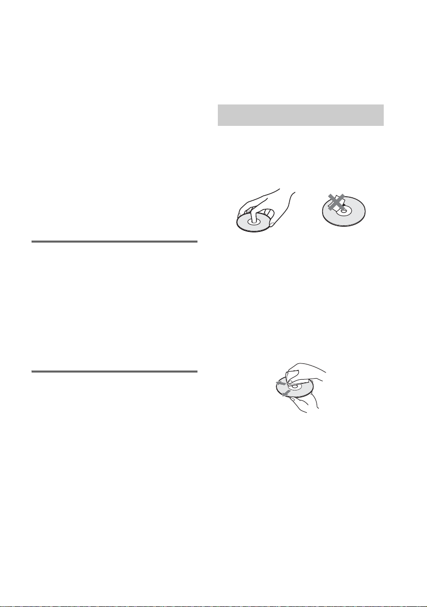
On handling discs
• To keep the disc clean, handle the disc by its
edge. Do not touch the surface.
• Do not s tick paper or tape on the disc.
Note on playback operations
of DVDs and VIDEO CDs
Some playback operations of DVDs and VIDEO
CDs may be intentionally set by software
producers. Since this system plays DVDs and
VIDEO CDs according to the disc contents the
software producers designed, som e playback
features may not be available. Also, refer to the
instructions supplied with the DVDs or VIDEO
CDs.
Copyrights
This product i ncorporates copyri ght protection
technology that is protected by U.S. patents and
other intellectual property rights. Use of this
copyright protection technology must be
authorized by Macrovision, and is intended for
home and other limited viewing uses only unless
otherwise author ized by Macrovisio n. Reverse
engineer i ng or disassembly is prohibited.
This system incorporates with Dolby* Digital
and Dolby Pro Logic (II) adaptive matrix
surround decoder and the DTS** Digital
Surround System .
• Do not expose the disc to direct sunlight or
heat sources such as hot air du cts, or l eave it in
a car parked in dir ect sunlight as the
temperature may rise considerably inside the
car.
• After pl aying, store the disc in its case.
On cleaning
• Befor e pl aying, clean the disc w ith a cleaning
cloth.
Wipe the disc from the center out.
• Do not use solvents such as benzine, thinner,
commercially available cleaners, or anti-static
spray intended for vi nyl LPs.
This system can only play back a standard
circular disc. Using neither standard nor circular
discs (e.g., card, heart, or star shape) may cause
a malfunctio n.
Do not use a disc that has a commercially
available acces s o r y at tached, such as a label or
ring.
US
9
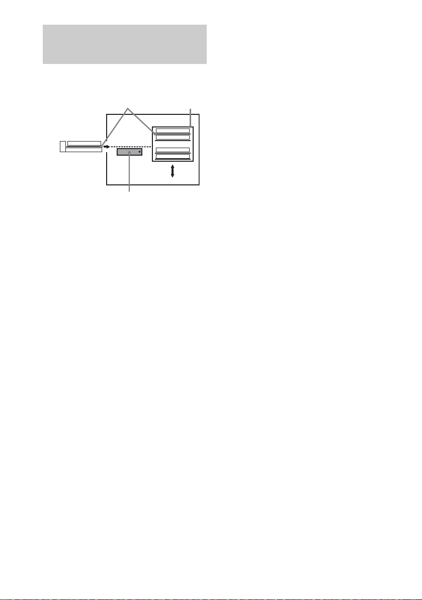
Note on DVD 5-DISC Changer
Disc changer system
Sub Tray
Disc
DISC 3
Main Tray
Playing unit
DISC 1
DISC 2
DISC 4
DISC 5
Stocker
The disc chan ger consi sts of a pl aying uni t, trays
which hold the discs and a stocker whi ch
transports the discs to the disc tray and the
playing unit.
For example, if you press DISC 3, the st ocker
moves until the DISC 3 comes to the positio n of
the playing unit and then moves the DI SC 3 over
the playing unit.
Note
Noise may come from the disc changer when changing
discs or turning the system on and off.
However, this is just noise produced by the operation
of the internal mechanisms and does not indicate a
malfunction.
10
US
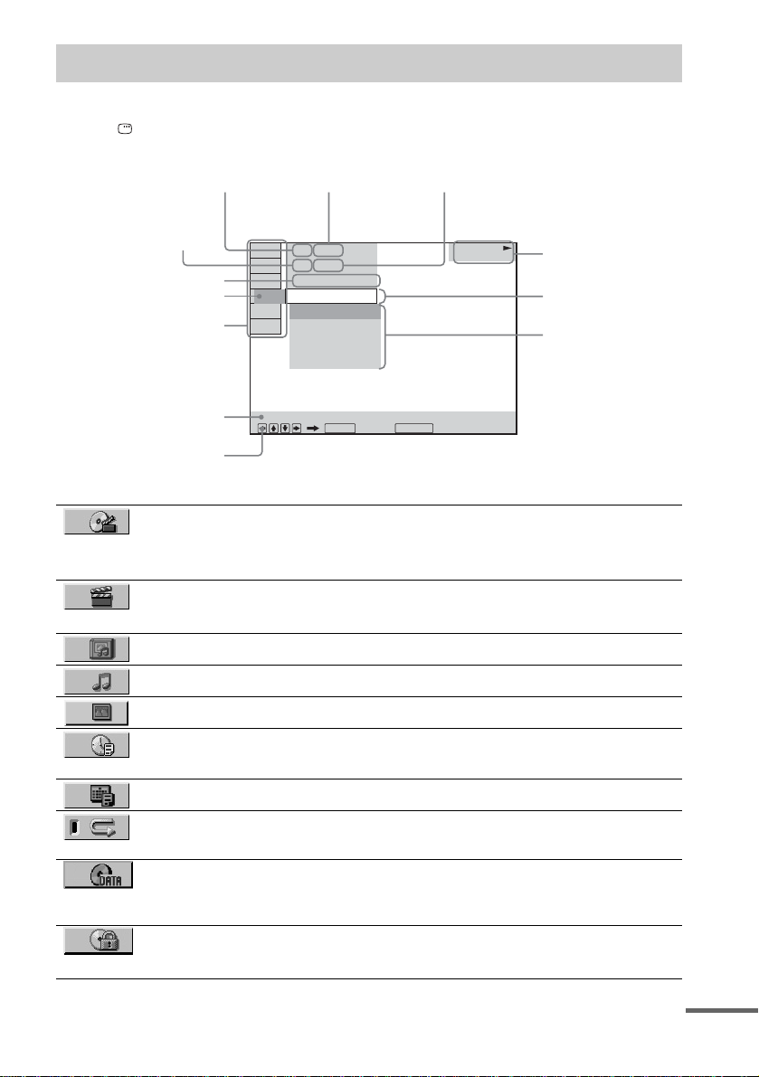
Guide to the Control Menu Display
Use the Control Menu to select a function that you would like to use. The Control Menu display appears
when the DISPLAY button is pressed. For details, refer to the page in parentheses.
Total number of
Currently playing title number (Video CD/
CD: track number)
Currently playing chapter
number (Video CD: index
number)
Playing time
Icon of selected
Control Menu item
Control Menu items
titles or tracks
recorded
)
1 2 ( 2 7
)
1 8 ( 3 4
T
1 : 3 2 : 5 5
OFF
OFF
ALL DISCS
ONE DISC
TITLE
CHAPTER
Total number of chapters or indexes recorded
Playback status
(NPlayback, XPause, xStop, etc.)
DVD VIDEO
Type of disc being
played back
Current setting
Options
Function name of selected
Control Menu item
Operation message
REPEAT
List of Control Menu Items
TITLE (DVD only) (page 43)/
SCENE (only VIDEO CD in PBC playback) /
TRACK (VIDEO CD only) (page 43)
CHAPTER (DVD only) (page 43)/
INDEX (VIDEO CD only) (page 43)
ALBUM (page 43) Selects the album (MP3/JPEG) to be played.
TRACK (CD/MP3 only) (page 43) Selects the track (CD/MP3) to be played.
FILE (JPEG only) (page 43) Select s the fi le (JPEG) to be played
TIME /TEXT (page 43) Checks the elapsed time and the remaining playback time.
DATE (JPEG only) (page 49) Displays the date information.
REPEAT (page 40) Plays the entire dis c ( al l titles/all tracks), one title/chapter/
DATA CD (page 36) Selects the data type; MP3 audio tr a c k (AUDIO), JPEG
PARENTAL CONTROL
(page 56)
ENTER DISPLAY
Quit:
Selects the title (DVD), or the track (VIDEO CD) to be
played.
Displays the scene (VIDEO CD in PBC play b ack).
Selects the chapter (DVD) or the index (VIDEO CD) to be
played.
Inputs the time code for picture and music searching.
track.
image file (IMAGE) or both (AUTO) to be played when
playing a DATA CD.
Set to prohibit playback on this system.
continued
11
US
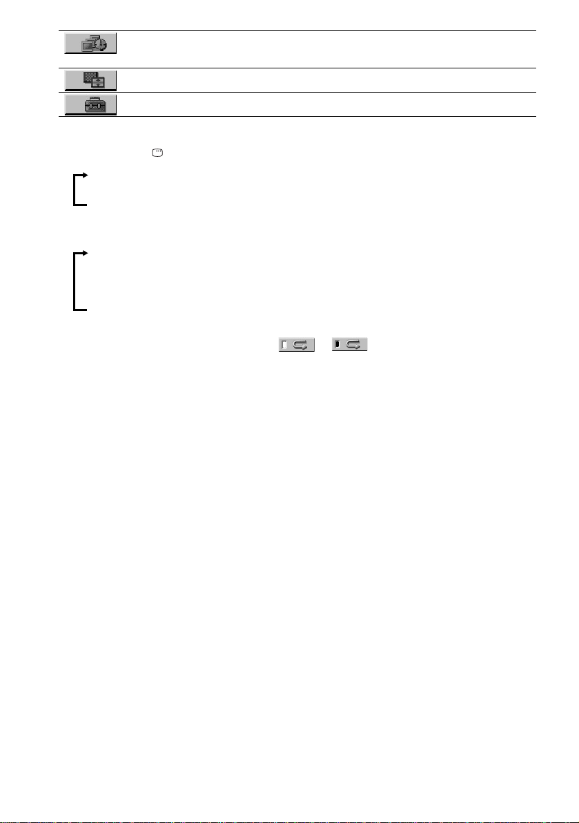
INTERVAL (page 38) Specifies the duration for which the slides are displayed on
EFFECT (page 39) Selects the effect to be used when viewing the slideshow.
SETUP (page 69) Sets various adjustments, suc h as pict ur e and sound.
Tips
• Each time you press DISPLAY, the Control Menu display changes a s fol lows :
Control Menu display
the screen.
m
Control Menu display off
x MP3, JPEG
Control Menu display (for MP3)
m
Control Menu display (for JPEG)
m
Control Menu display offControl Menu display off
The Control Menu items vary depending on the disc.
• The Control Menu icon indic a tor lights up in green t unless you set the [REPEA T ] setting to
[OFF].
12
US
Getting Started
Unpacking
Check that you have the following items:
•Speakers (5)
• Subwoofer (1)
• AM loop antenna (1)
• FM wire antenna (1)
• Spea ker cords (3.5 m × 3, 10 m × 2)
(11.5 ft. × 3, 33 ft. × 2)
• Video Cord (1)
• Remot e Commander (remote) RM-SS251 (1)
• Size AA (R6) batteries (2)
• Foot pads
DAV-BC150 (15)
DAV-BC250 (10)
• Operating Instructions
• Speakers-connection and Installation (card)
(1)
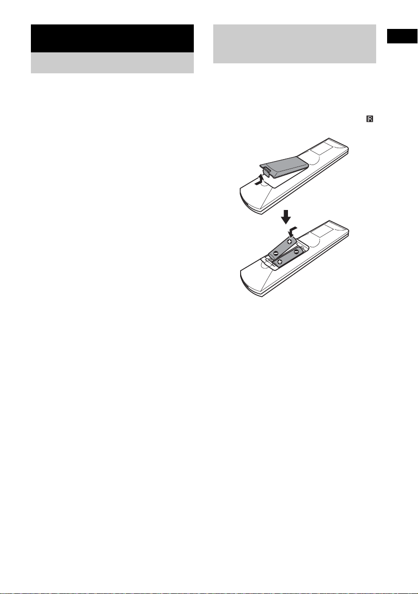
Inserting Batteries into
Getting Started
the Remote
You can control the system using the supplied
remote. Insert two Size AA (R6) batteries by
matching the 3 and # ends on the batteries to
the markings inside the compartment. When
using the remote, point it at the remote s ensor
on the system.
Notes
• Do not leave the remote in an extremely hot or humid
place.
• Do not use a new battery with an old one.
• Do not drop any foreign object into the remote casing,
particularly when replac ing th e ba tteries.
• Do not expose the remote senso r to dir ect light from
the sun or lighting apparatus. Doi ng so ma y c au se a
malfunction.
• If you do not intend to use the remote for an extended
period of time, remove the batteries to avoid possible
damage from battery leakage and corros ion.
13
US
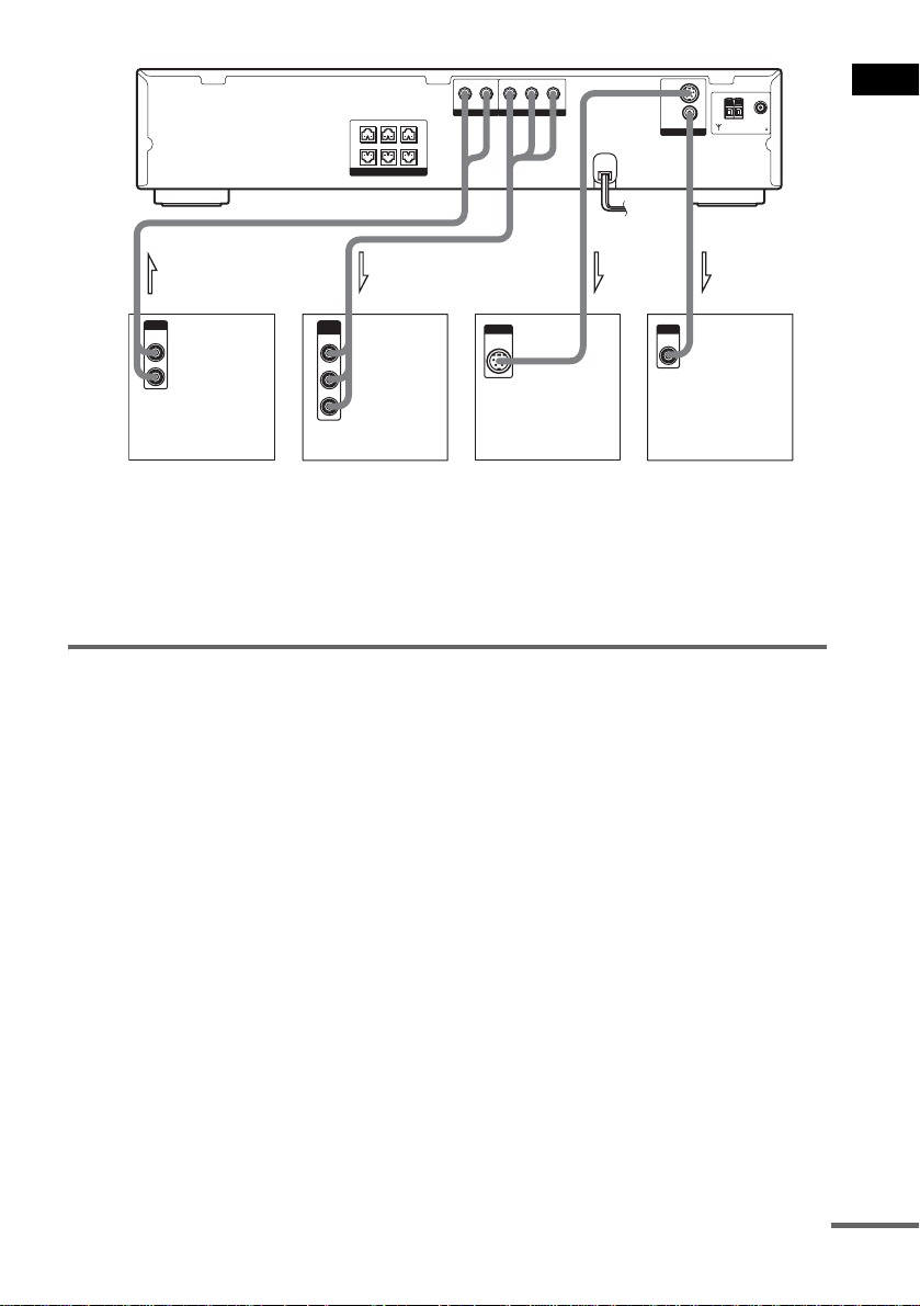
Step 1: Speaker System Hookup
Connect the supplied speaker sy st em using the supp li ed speaker cords by matching the colors of the
jacks to those of the cords. Do not connect any speakers other than those supplied with this system.
To obtain the best possible surround sound, specify the speak er par ameters (distance, level, etc.) on
page 24.
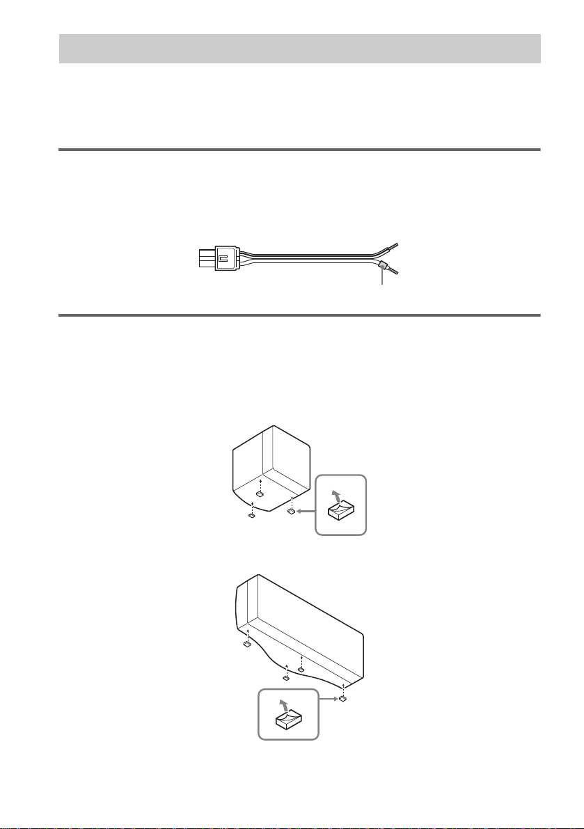
Required cords
Speaker cords
The connector and the color tube of the speaker cords are the same color as the label of the jacks to be
connected.
(–)
(+)
color tube
To attach the foot pads
To prevent speaker vibration or movement while listening, attach the supplied foot pads to the speaker,
as shown.
x BC150 Front/Center/ Surround
BC250 Surround
(–)
(+)
14
x BC250 Center
US
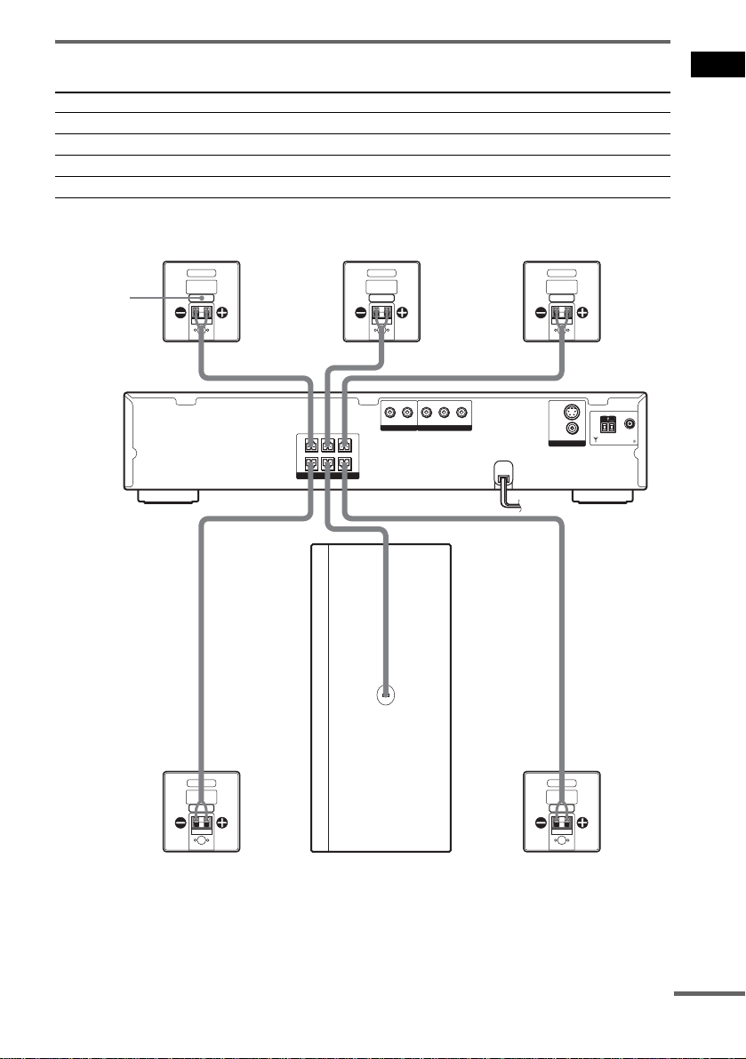
Terminals for conne cting the speakers
Connect the To the
Front speakers SPEAKER FRONT L (white) and R (red) ja cks
Surround speakers SPEAKER SURR L (blue) and R (gray) jacks
Center speaker SPEAKER CENTER (green) jack
Subwoofer SPEAKER WOOFER (purple) jack
DAV-BC150
Front speaker (R) Center speaker Front speaker (L)
color label
AUDIO IN
Y
PB/CBPR/C
R
L
R
COMPONENT VIDEO OUT
FRONT R
CENTER FRONT L
SURR R SURR LWOOFER
SPEAKER
VIDEO/SAT
(
S
DVD ONLY
VIDEO
VIDEO
MONITOR OUT
Getting Started
)
COAXIAL
75
AM
FM
Surround speaker (R)
Subwoofer
Surround speaker (L)
continued
15
US
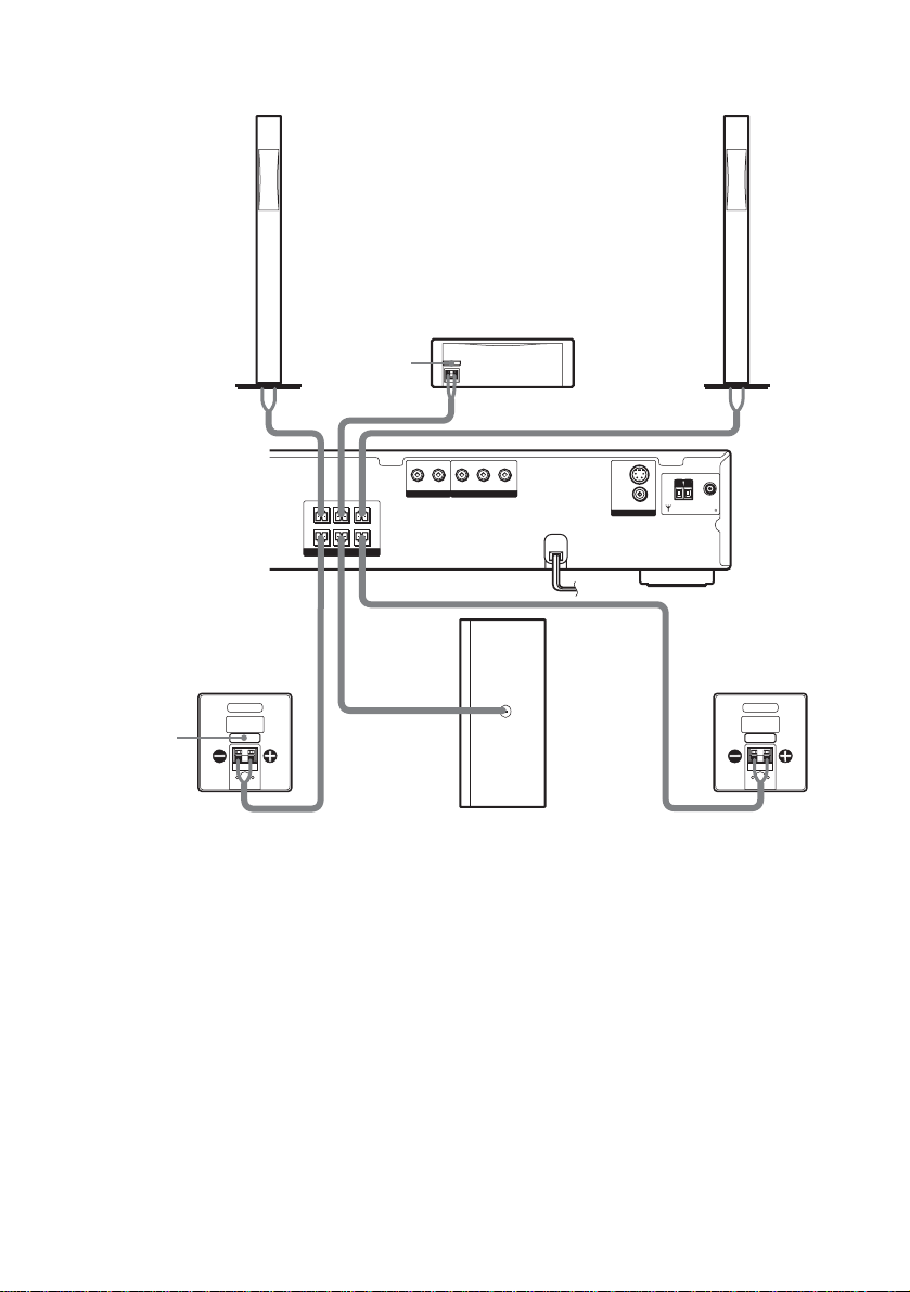
DAV-BC250
Front speaker (R)
color label
FRONT R
CENTER FRONT L
SURR R SURR LWOOFER
SPEAKER
Center speaker
AUDIO IN
Y
L
R
COMPONENT VIDEO OUT
VIDEO/SAT
PB/CBPR/C
Front speaker (L)
(
)
S
DVD ONLY
R
VIDEO
VIDEO
MONITOR OUT
COAXIAL
75
AM
FM
16
color label
Surround speaker (R)
Subwoofer
Surround speaker (L)
Notes on placing speakers
• Do not set the speakers in an inclined position.
• Do not place the speakers in locations that are:
– Extremely hot or cold
– Dusty or dirty
– Very humid
– Subject to vibrations
– Subject to direct sunlight
• Use caution when placing the subwo of er or a spea k er st and (not suppl ie d) tha t is a tta c he d with the front/surround
speakers on a specially treated (waxe d, oile d, polished, etc.) floor, as staining or discol orat ion may result.
US
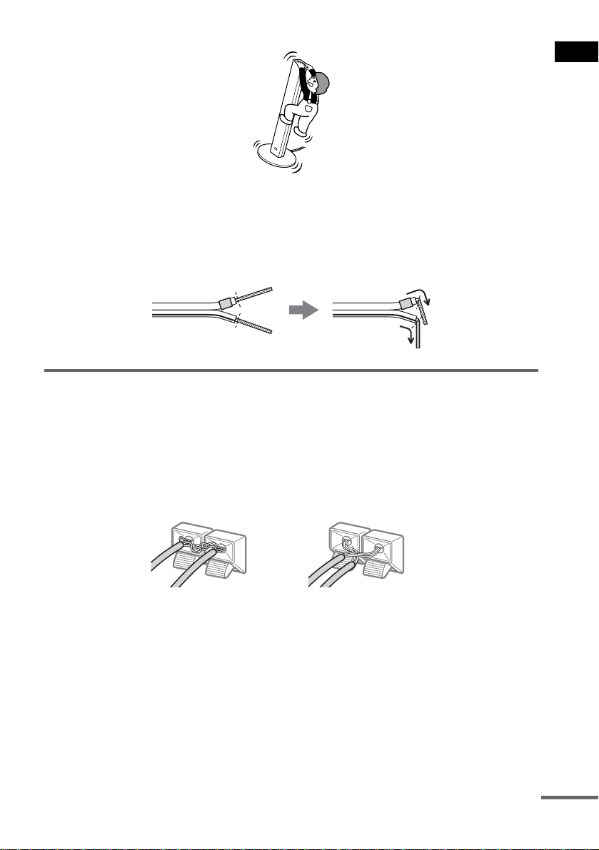
• Do not lean or hang on the speaker, as the speaker may fall down.
Note
Do not catch the speaker cab le insulation in the SPEAKER jack.
Tip
Connect the speaker cable aft er bendi ng the speak er wire at the en d of the in sulation . This pre vents the speaker ca ble
from being caught in the SPEAKER jack.
To avoid short -circuiting th e speakers
Short-circuiting of the speakers may damage the system. To prevent this, be sure to follow these
precautions when connecting the speakers. Make sure the bare wire of each speaker cord does not touch
another speaker jack or the bare wire of another speaker cord.
Examples of poor conditions of the speaker cord
Stripped speaker cord is
touching another speaker
terminal.
Stripped cords are touching
each other due to excessive
removal of insulation.
Getting Started
After connecting all the components , spea kers, a nd AC power cord, o utput a t est to ne to check th at all
the speakers are connected correctly. For details on outputting a test tone, see page27.
If no sound is heard fro m a speaker while outputting a test tone, or a test tone is output from a speak er
other than the one curren tly disp laye d in the f ront pa nel disp lay, the spe aker may be shor t-cir cuited. If
this happens, check t he speaker connectio n again.
Note
Be sure to match the speaker cord to the appropriate terminal on the components: 3 to 3, and # to #. If the cords
are reversed, the sound will lack bass and may be distorted.
continued
17
US
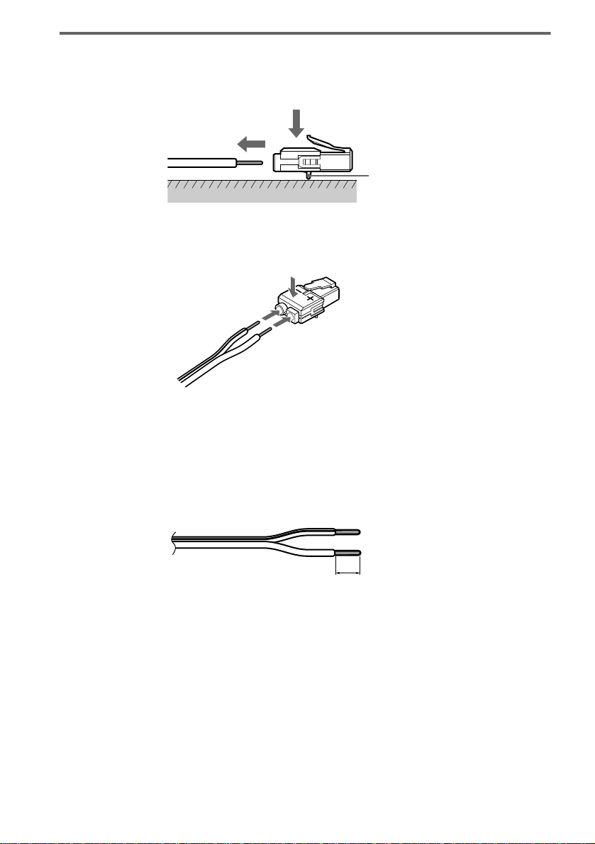
To change the speaker cable s
If you want to use a di fferent speaker cabl e, you can detach the plug for attachment to another cable.
Detaching
Catcher
With the catcher facing down, press and hold the plug down against a flat surface and remove the cords
from the plug.
Attaching
While pressing th e plug down against a fla t surface, insert the new speaker cords.
Note that the cord marked with a line should be attached to the minus (-) side of the plug.
Note
Be careful not to damage the surface you use (d es k , etc.) when attaching/detaching the speaker cord s .
Tips
• You can use any commercially sold speaker cable of gau ge cord AWG #18 - AWG #24.
• Before attaching a new cable, strip off 10 mm (13 /32 in. ) of its insulation and twist the bare wires of both cords.
18
10 mm
US
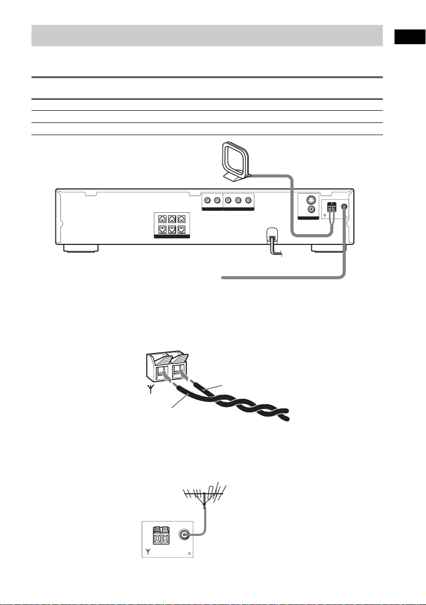
Step 2: Antenna Hookups
Connect the supplied AM/FM antennas for listening to the radio.
Terminals for conne ct ing the antennas
Connect the To the
AM loop antenna AM terminal
FM wire antenna FM 75Ω COAXIAL jack
AM loop antenna
(
)
S
DVD ONLY
AUDIO IN
Y
PB/CBPR/C
R
L
R
COMPONENT VIDEO OUT
FRONT R
SURR R SURR LWOOFER
SPEAKER
CENTER FRONT L
VIDEO/SAT
FM wire antenna
Notes
• To prevent noise pickup, keep the AM lo op antenna away from the system and other com ponents.
• Be sure to fully extend the FM wire antenna.
• After connecting the FM wire antenna, keep it as horizontal as possible.
• When you connect the supplied AM lo op an te nna , cord (A) or cord (B) can be connected to either terminal.
VIDEO
VIDEO
MONITOR OUT
COAXIAL
75
AM
FM
Getting Started
AM
A
B
Tip
If you have poor FM reception, use a 75-ohms coaxial cable (not supplied) to connect the system to an outdoor FM
antenna as shown below.
System
AM
COAXIAL
FM
75
Outdoor FM
antenna
19
US
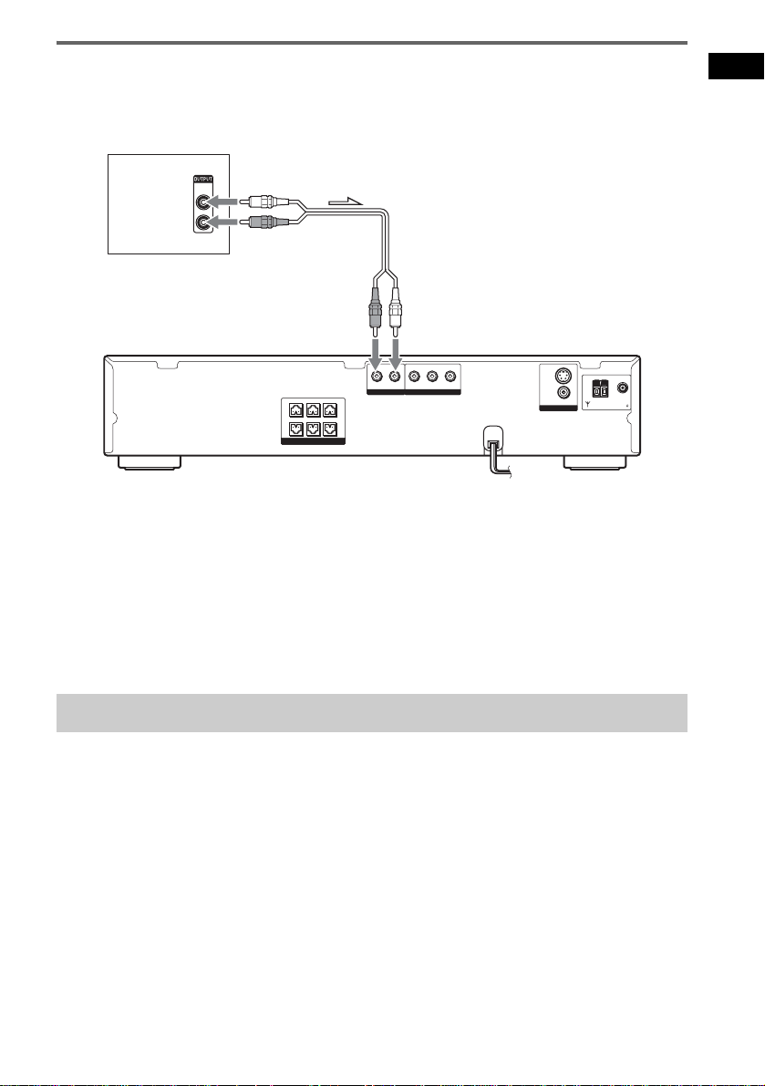
Step 3: TV and Audio Component Hookups
(
)
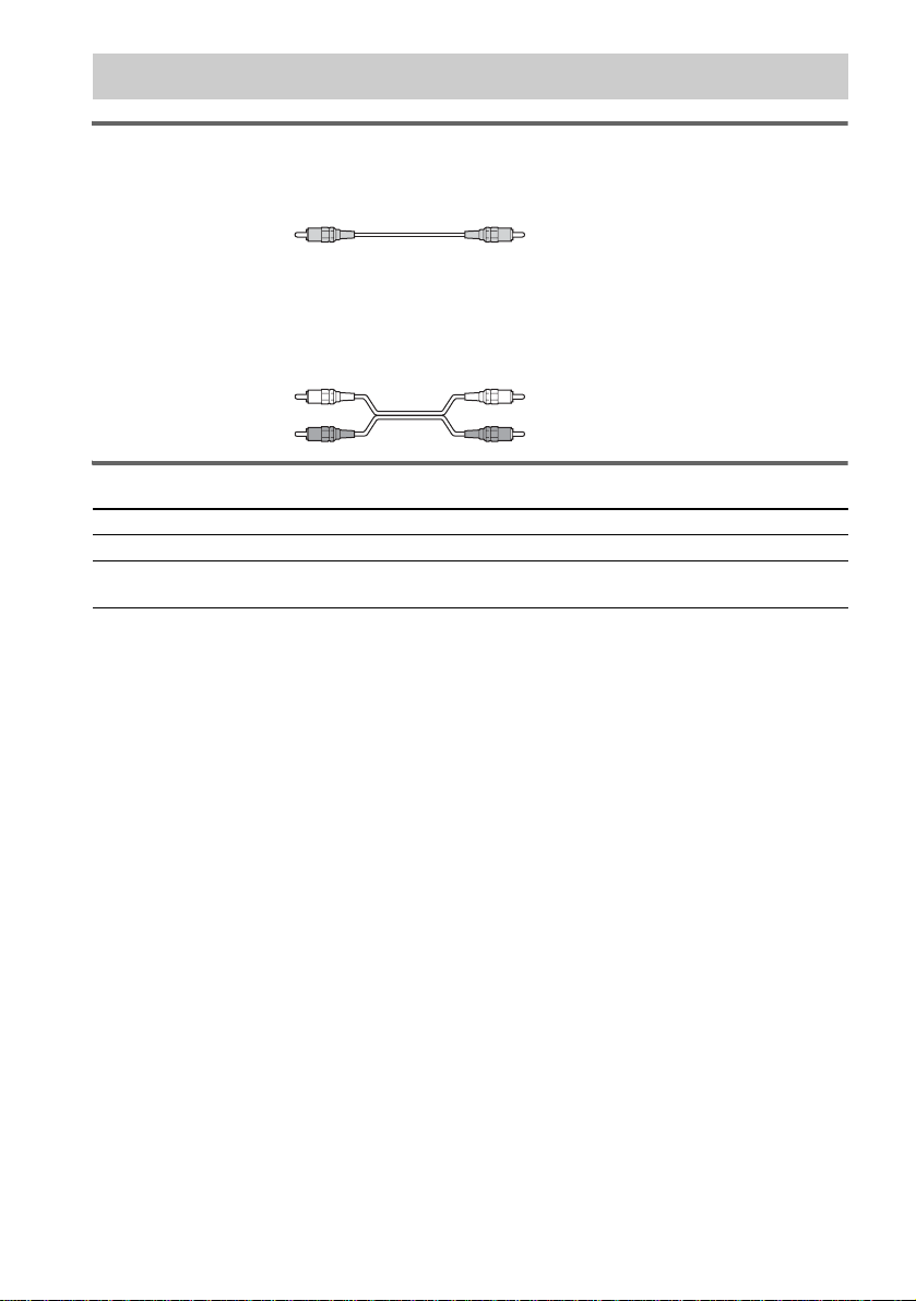
Required cords
Video cord for connecting a TV
Audio cords (not supplied)
When connecting a cord, be sure to match the color-coded sleeves to the appropriate jacks on the
components.
White (L/audio)
R/audio
Red
Terminals for connecting video and audio components
Connect the To the
TV (VIDEO IN) MONITOR OUT (VIDEO) jacks
VCR/Digital satellite receiver
(AUDIO OUT)
Notes
• When the system is set to “DVD” mode, the signal is output from the S VIDEO OUT jack or COMPONENT
VIDEO OUT jacks.
• When the system is set to “DVD,” and progressive format is selected, the signal is output only from the
COMPONENT VIDEO OUT jacks.
• When you connect a VCR or digital sate ll ite receive r to the VI DEO/SAT ja cks of th is system, ch ange t he funct ion
to VIDEO (page 63).
Tips
• When using the S video jack instead of the video jack, your TV monitor must also be connected via an S video jack.
S video signals are on a separate bus from the video signals and will not be output th ro ugh the vide o ja c ks.
• When using the COMPONENT VIDEO OUT jacks (Y, P
must also be connected via COMPONENT VIDEO OUT jacks (Y, P
format signals, use this connection and set to progressive fo rma t ( page 61).
VIDEO/SAT (AUDIO IN) jacks
B/CB, PR/CR) instead of the video jacks, your TV monitor
B/CB, PR/CR). If your TV accepts progressi v e
20
US
FRONT R
CENTER FRONT L
SURR R SURR LWOOFER
SPEAKER
AUDIO IN
VIDEO/SAT
R
Y
L
COMPONENT VIDEO OUT
PB/CBPR/C
(
)
S
DVD ONLY
R
VIDEO
MONITOR OUT
VIDEO
COAXIAL
75
AM
FM
Getting Started
OUTPUT
AUDIO
OUT
L
R
VCR or Digital
satellite receiver
IN
COMPONENT
VIDEO IN
Y
P
B/CB
PR/CR
TV with COMPONENT
VIDEO IN jacks
INPUT
S VIDEO
IN
TV with S VIDEO jack
INOUT
INPUT
VIDEO
IN
IN
TV
Notes
• Make connections securely to pr event unwanted noise.
• Refer to the instructions supplied with the TV.
• The system cannot output an audio signal to the connected TV. Only the audio signal of the TV is output from the
system speakers.
When connecting to a standard 4:3 screen TV
Depending on the disc, the image may not fit yo ur TV screen.
If you want to change the aspect ratio, please refer to page 71.
continued
21
US

Does your TV accept progressive signals?
Progressive is the method for displaying TV images which reduces flickering, and sharpens the image.
To display using thi s m e thod, you need to connect to a TV that accepts pro gr essive signals.
PROGRESSIVE
123
45
8
7
10
0
FUNCTION
6
9
1 Press FUNCTION repeatedly to select “DVD.”
2 Press PROGRESSIVE.
The current output signal “-NORMAL-” appears in the front panel display.
When “-PROGR E- ” appears in the front panel display, the output signal is alread y set to
progressive format.
3 Press PROGRESSIVE again while “-NORMAL-” appears in the front panel display.
The output signal is changed to progressive format and “PROGRE” appears in th e fr ont panel
display.
Tip
To return the setting to interla ce fo rma t repe a t the pr oc ed ur e above. When the output signal is changed to interlace
format, “NORM AL ” appears in the front panel disp lay.
See page 80 for more information about the different signal types.
Notes
• If your TV does not accept progre ssive sig nals and progr essive form at is set by mis take, the i mage may not appea r,
or will appear distorted. In th is c a se, return the setting to inter lace format (the defau lt se tting).
• If your TV accepts progressive signals, connect COMPONENT VI DEO OUT of the system to the TV using a
component video cord (not supplie d) , and set pr ogr e ssive format.
22
US
Output the TV or VCR sound from the speakers
Connect audio cords.
1
Connect the AUDIO OUT (L/R) jacks of TV or VCR to the VIDEO/SAT jacks (AUDIO IN L/R) of
this system wi t h audio cords.
*
AUDIO
OUT
L
R
TV
(
)
S
DVD ONLY
AUDIO IN
Y
PB/CBPR/C
R
L
R
COMPONENT VIDEO OUT
FRONT R
CENTER FRONT L
SURR R SURR LWOOFER
SPEAKER
VIDEO/SAT
* AUDIO OUT (L/R) jacks
If your TV does not have AUDIO OUT (L/R) jacks, you cannot output the TV sound from the speakers of this
system.
VIDEO
VIDEO
MONITOR OUT
COAXIAL
75
AM
FM
2 Change the mode of this system.
Press FUNCTION repeatedly to sel ec t “VIDEO” or “SAT,” (When you select “A TT O N , ” “SAT”
appears in the front panel display inst ead of “VIDEO.” (page 64))
Tip
When you want to output the TV sound or stereo sound of a 2 channel source from the 6 speakers, select any sound
field other than “AUTO FORMAT DIRECT” or “2CH STEREO” (page 51).
Getting Started
Step 4: Connecting the AC Power Cord
Before connecting the AC power cord of this syst em to a wall outlet, connect the speakers to the system
(page 14).
23
US
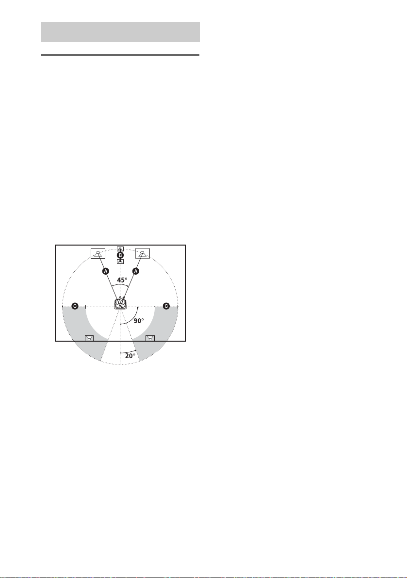
Speaker Setup
Positioning the speakers
For the best possible surround sound, all the
speakers other than the subwoofer should be the
same distance from the listening position (A).
However, this system allows you to place the
center speake r up to 1. 6 meter sa) closer (B) and
the surround speakers up to 4.6 meters
(C) to the listening position.
The front speakers can be placed from 1.0 to
7.0 meters
c)
(A) from the liste ni ng position.
North American numerical equival ent s:
a) 5 feet (1.5 meters)
b) 15 feet (4.5 meters)
c) 3 to 23 feet (0.9 to 6.9 meters)
Place speakers as illustrate d belo w
b)
closer
About magnetically shielded
speakers (to prevent color
irregularity occurring on the TV
screen)
The subwoofer in this system is magnetically
shielded to prevent magnetic leakage. However,
some leakage may occur, as a high-strength
magnet is employed. If the subwoof er is u se d
with a CRT-based TV or projector, install the
subwoofer at least 0.3 meter (1 .0 foot) from the
TV set. If it is installed too close, color
irregularity may occur on the screen. If color
irregularity occurs, tu rn off the TV set once, th en
turn it on after 15 to 30 minutes. If color
irregularity occurs again, place the subwoofer
farther away from the TV set. If color
irregularity still occurs after performing the
above, make sure that no magnetic object is
placed near the subwoofer. Color irregularity
may occur as a result of interaction between the
subwoofer and the magnetic object.
Examples of possib le sources of magnetic
interference include: magnetic latches on a TV
stand, etc., healthcare devices, toy s, et c.
24
Note
Do not place the center and surround speakers farther
away from the listen ing position than the front
speakers.
US
Adjusting the speaker
45
8
0
6
7
10
9
settings by using the front
panel display on the system
You can set speaker settings using the AMP
menu displayed in the front panel.
AMP menu List
SP SETUP
CENTER SP
SURR SP
F DIST
CEN DIST
SURR DIST 1.0 m - 7.0 m/3ft - 23ft
LEVEL
T.TONE
F BALANCE
CEN LEVEL
SL LEVEL
SR LEVEL
SW LEVEL
AUDIO DRC
CUSTOMIZE
DIMMER
ATTENUATE
CENTER Y
CENTER N
SURR Y
SURR N
1.0 m - 7.0 m/3ft - 23ft
1.0 m - 7.0 m/3ft - 23ft
T.TONE ON
T.TONE OFF
6 steps left or right
–6 dB - +6 dB
–6 dB - +6 dB
–6 dB - +6 dB
–6 dB - +6 dB
DRC OFF
DRC STD
DRC MAX
DIM ON
DIM OFF
ATT ON
ATT OFF
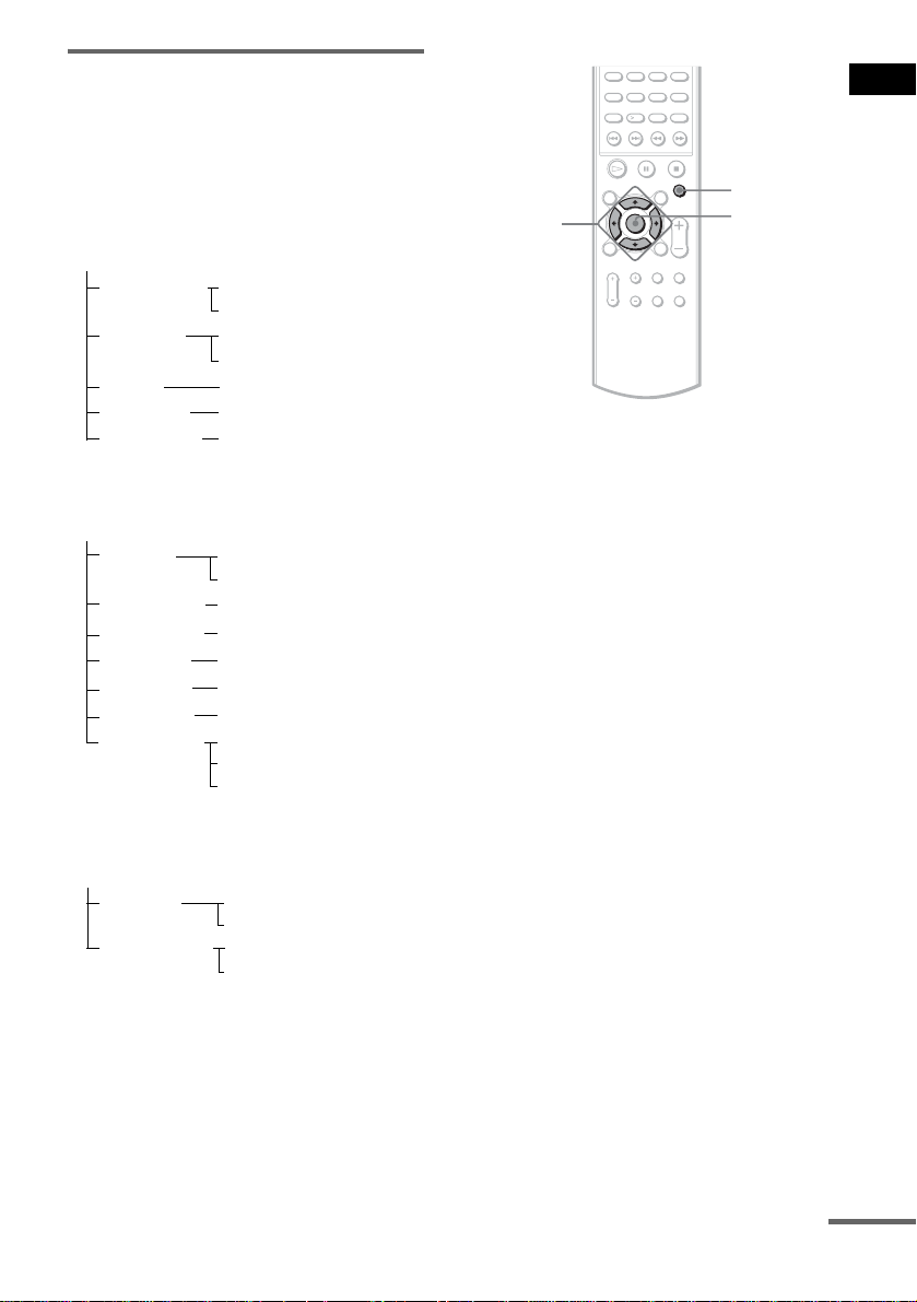
AMP MENU
C/X/x/c
ENTER
1 Press AMP MENU.
2 Press X/x until the item you want to set
appears in the front panel display, then
press ENTER or c.
x SP SETUP
Sets the speaker size and distance.
x LEVEL
Sets the balance and level of each speaker,
sets AUDIO DRC and the test tone (on or
off).
3 Press X/x to select the desired item,
then press ENTER or c to select the
desired setting.
4 Press X/x to select each setting of the
desired item.
You can set the fo llowing items. The def ault
settings are underlined.
Note
While the AMP menu is displayed, the C/X/x/c
buttons do not work for setting the Control menus, the
DVD Setup menus, and the menus in DVD discs. Press
AMP MENU to cancel the AMP menu, and set the
Control menus and the DVD Setup menus.
Getting Started
continued
25
US

x SP SETUP
If you do not connect center or surround
speakers, or move th e surround sp eakers, se t the
parameters for CENTER and SURROUND.
CENTER SP
(center
speaker)
SURR SP
(surround
speaker)
F DIST
(front
distance)
F D 3.0 M
F D 10F*
CEN DIST
(center
distance)
C D 3.0 M
C D 10F*
SURR DIST
(surround
distance)
S D 3.0 M
S D 10F*
* Only for North American models.
Notes
• In SP SETUP, the North American model’s OSD
displays both metric and imperial measurements. The
other model displays metric measurements only. The
manual shows both.
• When you set the distance, the sound cuts off for a
moment.
• If all front and surround speakers are not placed at an
equal distance from your liste ning position, set the
distance according to the closest speaker.
• Do not place the surround speakers farther away from
your listening position than the front speakers.
• Depending on the settings of other speakers, the
subwoofer may output excessive sou nd.
CENTER Y: Select this if you us e a
center speaker.
CENTER N: Sele ct this if no center
speaker is used.
SURR Y: Select this if you use
surround speakers.
SURR N: Select this if no surround
speaker is used.
Front speaker distance from the
listening position can be set in
0.2 meter (1 ft) increments from
1.0 to 7.0 meters (3 to 23 ft).
Center speaker distance ca n be set up
to 1.6 meters (5 ft) forward closer t o
the listening position, in 0.2 meter
(1 ft) increments.
Surround speaker distance can be set
up to 4.6 meters (15 ft) closer to your
listening position from the front
speaker position, in 0. 2 me te r (1 ft)
increments.
x LEVEL
The speakers will emit a test tone to adjust
“LEVEL” items.
T.TONE
(test tone)
T.TONE OFF: The test tone is not
emitted from the speakers.
T.TONE ON: The test tone is
emitted from both left and right
speakers simultaneo usly while
adjusting balanc e. Wh en you se lect
one of the “LEVEL” ite ms , th e test
tone is emitted from each speaker in
sequence.
You can vary the bal ance of the left and right
speakers as follows. Be sure to set “T.TONE” to
“T.TONE ON” for easy adjustment.
F BALANCE
(front
balance)
F BAL 0
Adjusts the balance between the
front left and right speakers. (You
can adjust from the center 6 steps lef t
(F BAL L6) or right (F BAL R6).)
You can vary the level of each speaker as
follows. Be sure to se t “ T.TONE” to “T.TONE
ON” for easy adjus tment.
CEN LEVEL
(center level)
SL LEVEL
(surround left
level)
SR LEVEL
(surround
right level)
SW LEVEL
(subwoofer
level)
Adjusts the level of the center
speaker (–6 dB to +6 dB, 1 dB
increments).
Adjusts the left level of the surround
speakers (–6 dB to +6 dB, 1 dB
increments).
Adjusts the right level of the
surround speakers (–6 dB to +6 dB,
1 dB increments).
Adjusts the level of subwoofer
(–6 dB to +6 dB , 1 dB increments).
26
US

Narrows the DYNAMIC range of the sound
track.
Useful for watching movies at low volume late
at night.
AUDIO DRC
Note
DYNAMIC range compression only applies to Dolby
Digital sources.
DRC OFF: No compression of
DYNAMIC range.
DRC STD
track with the kind of DYNAMIC
range that the recording engineer
intended.
DRC MAX: Fully narrows the
DYNAMIC range.
: Reproduces the sound
Adjusting the speaker
balance and level by using the
test tone
1 Press AMP MENU.
2 Press X/x until “LEVEL” appears in the
front panel display, then press ENTER
or c.
The system enters th e Level Menu mode.
3 Press X/x repeatedly to select
“T.TONE” in the front panel display,
then ENTER or c.
4 Press X or x to select “T.TONE ON” in
the front panel display.
You will hear the tes t t one from each
speaker in sequence.
When you select “T.TONE OFF,” this
operation will be canceled.
5 Press C to return “T.TONE”.
6 Press X/x to select the item you want to
set, then press ENTER or c.
7 Press X/x to adjust the speaker setting
value.
Press C to return step 6 and follow steps 6
and 7 to adjust other spea ke r setting values.
8 Set “T.TONE” to “T.TONE OFF” to
cancel the test tone function.
Test tone sound stops emitting.
9 Press AMP MENU when you have
finished making adjustments.
Note
When you adjust the speaker settings, the sound cuts
off for a m o ment.
Getting Started
27
US
Playing Discs
Playing Discs
Depending on the DV D or VID E O CD, some
operations may be different or restricted.
Refer to the operation details supplied with your
disc.
Adjust the
"/1
Disc tray
STANDBY indicator
DISC SKIP
H
DISC 1-5 A
DISC1 DISC2 DISC3 DISC4 DISC5
123
45
6
9
8
7
10
0
H
volume
FUNCTION
Connect
headphone
"/1
FUNCTION
4 Press DISC 1-5 A.
Press the button of th e di sc number you
want.
“OPEN” appears in the front panel display
and the system is ready for loading the disc.
Example: Whe n you want to load the disc to
the disc stocker 1, pr ess DISC 1 A.
If there is a disc in th e stocker that you
select, the disc is ejected, “OPEN” appears
in the front panel display, then the system is
ready for loa di n g the disc.
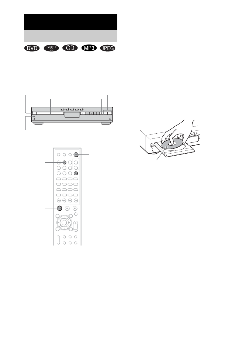
5 Load a disc.
Place one disc on the tray, and then press A.
The disc is drawn into the selected disc
stocker automatically and “READING”
appears in the fron t p anel display.
When you play an 8 cm disc, place it on the
inner circle of the tray. Be careful that the disc
is not skewed on the inner circle of the tray.
To load other discs, press DISC 1-5 A (that
is not loaded with a dis c) and load the disc.
Note
Do not place more than two discs on the tray.
28
1 Turn on your TV.
2 Switch the input selector on the TV to
this system.
3 Press "/1.
The system tur n s on.
Unless the system is set to “DVD,” press
FUNCTION to select “DVD.”
US
6 Press H.
The system starts playback (continuous
play) of the disc whose DISC indicator is
green.
To play back ot he r di scs, pr es s DIS C SKIP
on the remote or DIS C 1-DISC 5 of the
system. Adjust the volume on the system.
 Loading...