

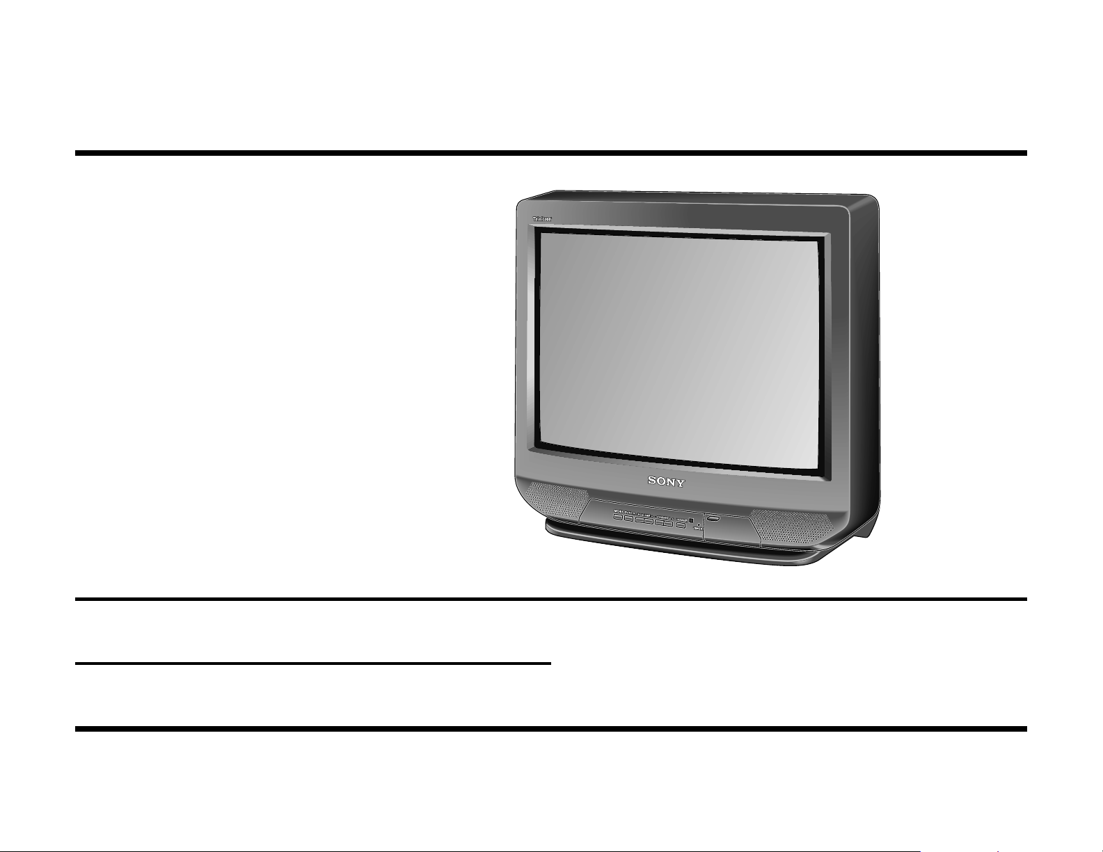
Sony CTV-25R1 Service Manual
S®
Color
Television
BA-4 Chassis
Manual de Treino
Circuit Description and Troubleshooting
Course: CTV-25R1

Table of Contents
Introduction
®
The Trinitron
The Trinitron Electron Gun Operation 1
The Trinitron Screen 7
Picture Tube Defect Symptoms 9
Picture Tube 1
Picture Tube Handling and Vacuum
Disposal 13
Overall Block Diagram 15
Power Supply 15
Communications 15
Video Processing 15
Deflection 15
Power Supply - 20” TV & Smaller 1 7
The Converter Stage 17
The Voltage Output Stage 17
The Power Output Control 17
Converter 19
The Rectifier 19
The Oscillator 19
Converter Voltage Outputs 29
Additional Circuits 33
Power Supply Block - 27” Models 37
Standby Power Supply 39
Basic Oscillator 39
Additional Components 41
B+ Regulation - 27” TV 45
Regulation 45
Soft Start Circuit 45
Power On/Communications Block 47
Degaussing Circuitry 49
Concept 49
Circuit Operation 49
Power ON 53
Communications 57
Start 57
Run 5 7
Video Processing Block 61
Tuner 6 1
Video Inputs 61
Digital Comb Filter 61
B+ Regulation - 13” & 20” TV 3 3
Regulation 33
Video Output 63

TV Reception 65
Reception from Power ON 65
Channel Change Audio Mute 65
Auto Station Programming 65
Video Inputs 69
Video Output 73
Spot Elimination Circuit 75
Troubleshootintg 77
Video Block - 27” With PIP 7 9
Picture in Picture (PIP) Board Signal Flow 79
Picture in Picture Processing 81
Deflection Block 83
Vertical Deflection 85
Horizontal Deflection 89
Protection 93
Troubleshooting 95
Self Diagnostic 9 9
Timer / Standby Light 99
Self-Diagnostic On Screen Display 99
Self-Diagnostic Circuit 101
Introduction
Sony TV Models Covered by this Manual
BA-4 Chassis – Current Models Covered
KV13M40 KV20M40 KV27S40 KV27V40
KV13M50 KV20M40 KV27S45 KV27V45
KV13M51 KV20S40 KV27S65 KV27V65
KV20S41
KV20V80
Purpose
The purpose of this book is to:
• Show through diagrams and explanation how the Sony Trinitron Picture tube now works because it has evolved since inception in
1968.
• Provide organized, simplified diagrams that provide an insight to understanding the necessities of the circuit’s operation. This is an
essential aid to rapidly determining the cause of a failure.
• Explain the circuit operation and provide tips for troubleshooting where needed. Some parts of the circuit are used only under certain
conditions of operation. It is important to know when these additional parts affect the main circuit during operation and how they affect
the main circuits if they are defective.
• Provide some voltages from a working production run set that are not supplied in the service manual. These can be compared to the
non-working unit you are repairing to determine where the fault is.
• Explain the new self diagnostic circuit:
1. How to access it
2. How it works,
3. When to use it
4. The circuits that support it
Note:
This note is common to all schematics and block diagrams.
All capacitors are
All resistors are
All voltages are
uf
unless otherwise noted.
ohms
dc
unless otherwise noted.
unless otherwise noted.

1
The Trinitron Picture Tube
The Cathode Ray Tube (CRT) has been slowly changing since its conception about 50 years ago. Since then the emitter, accelerator and
focus structures at the “gun” end have been added to the vacuum tube
to shape and control the amount of electrons from the gun.
At the target end of the CRT, the luminescent screen is made of a phosphor mixture. Phosphor glows white when struck by electrons. Phosphor brightness is directly proportional to the amount of electrons that
strike the phosphor. The CRT sport brightness was controllable with a
gun and phosphor screen.
The electron beam produced a spot of light that was stationary on the
phosphor screen. Placing an electromagnetic field near the electron
beam after it left the gun created movement. The spot intensity and
location were now controllable and the CRT became known as the picture tube.
To produce a color picture on the CRT screen; three independent gun
structures are used. The electron guns produce different amounts of
electrons targeted to their corresponding Red, Green and Blue phosphors. Red, Green and Blue are the primary colors for light.
In 1968 the Sony Trinitron picture tube was a departure from the traditional three-gun color picture tube. Three major changes to the old color
tube created a distinctive Trinitron picture tube:
1. Instead of three small electron guns, focus was improved using one
large electron gun structure that all three beams pass through.
2. Electrostatic convergence plates were added to bend the outer electron beams so they would land on the corresponding red and blue
color phosphor.
3. A continuous vertical slotted aperture grill at the screen end that:
• Reduces the effects of terrestrial magnetism.
• Prevents adjacent and stray electrons from striking the wrong phos-
phor.
• Allows more electrons to pass, increasing brightness without shortening life.
• Results in a flat screen. This reduces annoying room light reflections
(glare).
The remainder of this document is divided into four sections explaining
the construction of Trinitron tube as an aid to the service technician:
• The Trinitron Electron Gun Operation
• The Trinitron Screen
• Picture Tube Defect Symptoms
• Picture Tube Handling and Vacuum Disposal
The T rinitron Electron Gun Operation
The Sony Trinitron electron gun consists of three cathode assemblies,
five grid structures and convergence plates:
Three cathode assemblies
When heated, electrons are given off from a Barium Carbonate (BaCO3)
surface deposited onto a cap. The cap serves as a holder for the BaCO
white mixture. The cap is fastened to a sleeve that houses a heating
element (filament). This assembly is called a cathode.
There are three cathodes in the beginning part of the gun assembly by
the pins of the CRT. They all supply electrons in controlled amounts.
The center cathode on the Trinitron tube produces the amount of electrons that correspond to the green color information. These electrons
will eventually land on the green phosphor if things go well on the journey. The outer cathodes are angled slightly to send electrons through
the gun structure. Their final targets are the red and blue phosphor at
the screen.
Next a voltage is connected to the cathode (sleeve) and a more positive
voltage to the second grid (two) in the gun structure. This difference in
potential will pull the electrons from the cathode’s Barium Carbonate
(BaCO
age between the cathode and grid two will determine the amount of electrons emitted. More electrons landing on the phosphor (screen) will increase the color spot intensity.
) surface into the gun structure. The difference in potential volt-
3
3,

2
3
Five Grid Structures
The electron gun consists of the cathode and several metal rings called
grids. The grid name came from the controlling grids in a vacuum tube
where the interelectrode elements were originally shaped like a screen
mesh. There is no structural resemblance between the picture and
vacuum tube grids. In the picture tube, the grid rings are applied different electrical potentials to focus (shape) and accelerate (speed) the electrons from the cathodes. Each part of the gun has a voltage applied to it
for a specific purpose.
Trinitron Electron Gun Parts
Name Purpose Applied Voltage
Filament / Heater
(Inside the cathode
assembly).
Cathode assembly Houses the electron
Grid 1 / Control Grid Reference potential for
Grid 2 / Screen Grid Brightness limit. 400Vdc (approx.)
Grid 3 / Accelerating Accelerate stream. HV from FBT*.
Grid 4 / Focus Sets focus point. 300Vdc (approx.)
Grid 5 / Acceleratin g Post Accelerating. HV from FBT*.
*FBT = Flyback Transformer in consumer TVs. Transformer is assembled with
rectifiers in a doubler or tripler configuration to develop 25-35kV of DC. The high
voltage is used in the pi cture t ube to accelerate electro ns. Larger picture tubes
require a higher high volt age from the F BT to move the electrons a longer dis tance.
Brings the cathode to
emission temperature.
emitting chemical and the
heater.
cathode emission.
Control Grid One
Electrons at the cathode are attracted to a positive potential. The grid
one ring is the next electrode structure in the electron gun. In consumer
TVs, grid one is fixed at a 0Vdc potential for reference. If a positive
potential were placed on the cathode, electrons would not be attracted
to grid one. At a +200Vdc potential, electrons would not leave the cathode. If no electrons enter the gun, the TV screen is dark. The picture
tube is said to be in “cutoff”.
Test voltage = 6 Vdc @
0.64 Amp. Actual vol tage
= FBT pulse , 6V rms.
R, G or B signal voltage.
+200V= Cutoff. No
electrons output.
0V = All electrons output.
Ground vi a current
limiting resistor.
Focus Control range
= 200Vdc to 1kVdc.
On the other hand, placing the cathode at the same potential as grid one
(0Vdc) is the same as if grid one were invisible. The maximum amount of
electrons is attracted toward the positive grid two structure, resulting in
maximum screen brightness.
By varying the voltage at the cathode from 0 Vdc to +200Vdc (cutoff), the
amount of electrons available to the gun structure to produce screen
brightness can be controlled.
Screen Grid Two
The higher voltage at the second grid ring accelerates the electron beam.
This voltage is connected to the TV circuitry’s “screen control”. The screen
control is adjusted to limit the maximum beam acceleration (brightness).
This limit avoids over driving the tube which shortens the life of the cathodes and phosphors.
Acceleration Grid Three
The very highest voltage in a TV (from the flyback transformer) is applied
to the third grid ring. This creates a large magnetic field to further accelerate the three electron streams from the cathodes.
Focus Grid Four and Acceleration Grid Five
The lower voltage at focus grid ring four slows down the electron stream
so they bunch up, thickening the beams. By varying the focus voltage
applied to grid four, the beam thickness is controlled. A thicker beam
means the electron stream will focus at a point closer to the gun (before
the screen).
When a very bright spot is called for, more electrons are sent from the
cathodes. As a result the beam is at its thickest at the G4 focus ring. In
a small electron gun, the G4 focus ring is closer to the thick beam than
the single Trinitron gun where the focus ring is much larger.
Grid four’s magnetic field is the strongest at the metal grid ring. More
peripheral electrons are attracted to the focus grid ring of the smaller
electron gun. Some of these peripheral electrons are lost from the stream
as G4 grid current, limiting beam thickness. The limited beam thickness
results in a shift in focus point. This causes reduced focus during brightness peaks in the smaller electron gun. Therefore, at high brightness
levels it is advantageous to have a large G4 focus structure. A wider
dynamic focus range is achievable with the large single Trinitron gun.

4
5
Grid ring five is applied a very high voltage to accelerate the beam so it
comes to a fine point some distance away (at the center of the screen).
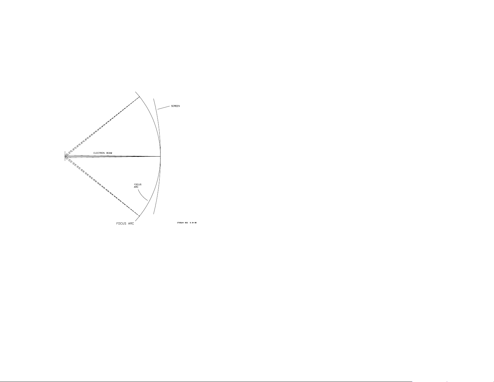
The ratio of voltages at G4 and G5 determines where the focus point is
positioned. This focus point forms an arc when the electron beam is
swept from left to right by the deflection yoke.
Unfortunately, the picture tube screen does not match this focus arc, so
the beam will only be in focus at the center of the screen. To correct this
physics problem, the G4 focus grid voltage is modulated with a parabolic
waveform (shape is like a bowl) at the horizontal rate. The parabolic
waveform moves the focus points forward so they match the screen.
In a TV, high voltage drops during bright scenes because of heavy current demands. When the high voltage applied to grid five drops, the G4G5 focus voltage ratio changes. This voltage change causes the focus
point to change during the brightest spots. One method to maintain the
focus voltage ratio is to take both the focus voltage for G4 and high
voltage for G5 from the same flyback secondary transformer winding. If
G5’s high voltage drops, so does the G4 focus voltage. The focus voltage ratio and picture focus are maintained during bright scene changes.
The focus is customarily adjusted for sharpness when snow (no station)
is present. The rapid changes from black to white when snow is displayed on the screen are the most taxing on the high voltage system.
Setting the focus under these dynamic conditions will insure a well focused picture within the normal viewing range.
Convergence Plates
The Trinitron gun uses one gun, which three electron beams pass through.
These three beams diverge as they pass out of the gun. Electrostatic
convergence plates bend the outer electron beams back so they land
adjacent to the center electron beam on the corresponding red and blue
phosphors.
Four convergence plates are used to bend the outer electron beams.
The two center plates are connected to the flyback generated high voltage. The two outer plates are connected to a voltage a few hundred
volts less than the high voltage. A variable resistor (CV) external to the
picture tube determines the exact voltage.
As the outer two electron beams pass through the convergence plates,
they are bent (attracted) inward toward the higher voltage plate. Adjusting the CV control changes the voltage to the outer convergence plates.
The deflection angle of the outer beams can be changed so they converge and pass through the same aperture grill slot by the screen as the
center green beam. After the beams pass the aperture grill, they diverge
to land on their corresponding red, green and blue phosphors to produce
a white dot.
An incorrect adjustment of this CV control causes the outer beams to
pass through other slots in the aperture grill. The outer beams will produce a red and blue dot near the green one instead of a single white dot.
There is no CV control in newer Sony TV sets. The CV control end of the
picture tube’s high voltage resistor is grounded so there is still a difference in convergence plate potiential. Plastic rings with tabs called “VStat” control permit you to magnetically perform the same static convergence as the CV control. These plastic rings are located at the back of
the yoke and contain a few small pieces of metal molded into the plastic.
This metal alters the yoke’s magnetic field for beam convergance.

6

7
The Trinitron Screen
In front of the electron gun are the:
• Deflection Yoke
• Aperture Grill (AG)
• Phosphor Stripes
• Getter Assembly
Deflection Yoke
The yoke consists of two coils of wire mounted on the glass bell of the
picture tube in front of the (internal) convergence plates. One coil generates a magnetic field to move the electron beams in the X-axis and the
other coil moves the beams in the Y-axis. Guided by the deflection yoke,
three electron beams first sweep across the aperture grill along the Xaxis from left to right (from the front as you would watch TV). At the end
of the horizontal sweep, the beam retraces back to the left side of the
screen. Meanwhile the yoke’s magnetic field moves the three beams
down (Y-axis) one line before the beams sweep horizontally across the
aperture grill again. This process then repeats. Finally, at the bottom
right corner of the picture, the beams are returned to the top left corner of
the screen.
The deflection yoke has difficulty providing a magnetic field to sweep the
beam so it matches the screen shape. The yoke’s magnetic field is stronger at the corners of the picture then at the top/bottom and sides (X & Yaxis).
Improvements in deflection yoke construction have compensated for the
reduced top/bottom deflection (Y-axis). Along the X-axis, the weaker
magnetic field causes the picture to look like an hourglass. This is because there is insufficient picture scan, which produces a dark area at
the left and right sides of the picture tube.
Increasing the current through the horizontal windings of the yoke compensates for this hourglass picture. The yoke current is then gradually
increased line by line until the middle of the picture for maximum width ,
the curve is reduced as the beam continues to scan downward. The
result is a straight picture. This type of yoke distortion to the picture is
called pincushion distortion. The correction circuit that changes the yoke
current is called the pincushion stage.
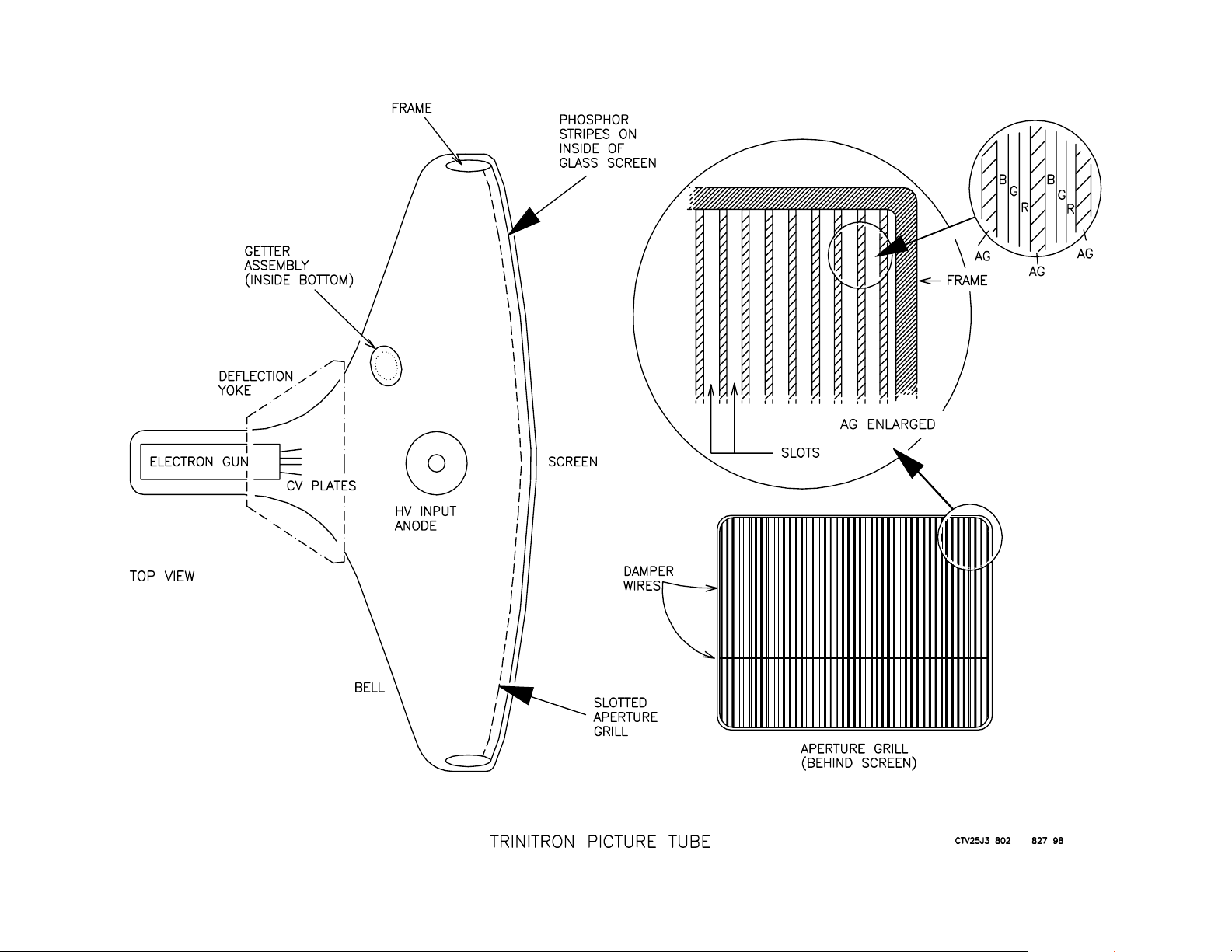
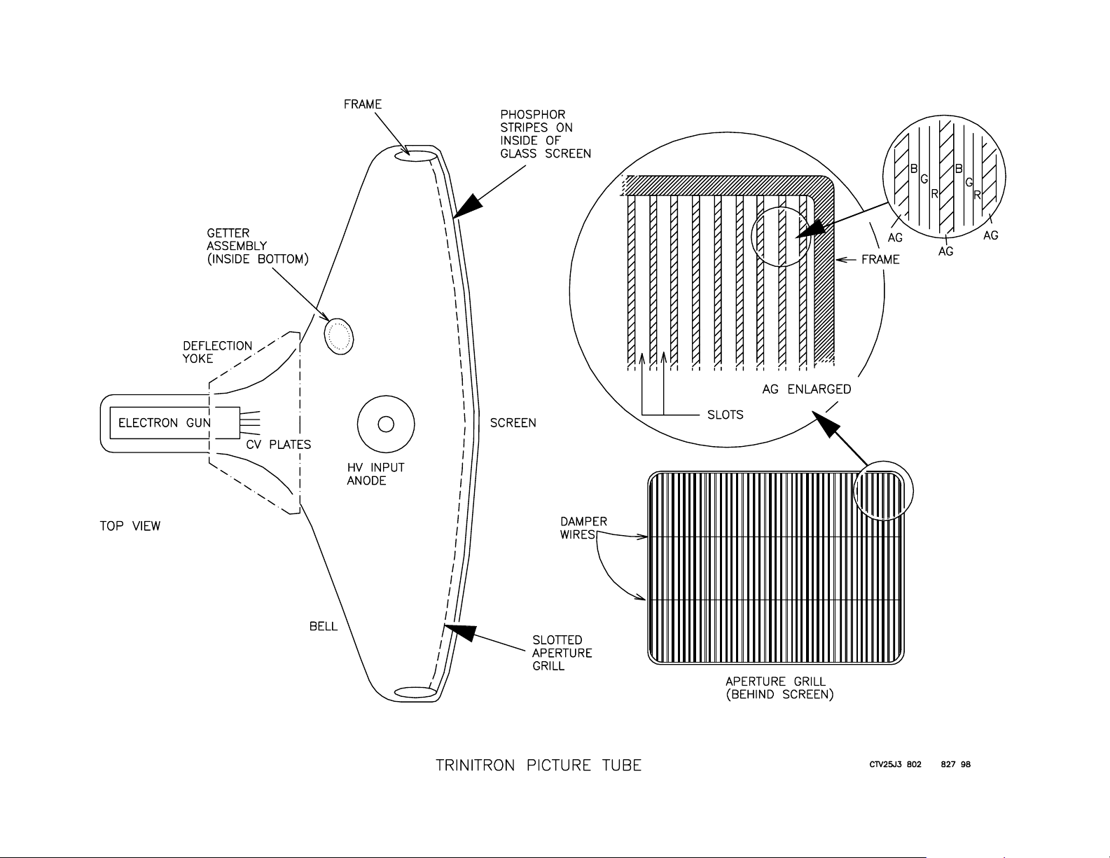
Aperture Grill Construction
The aperture grill (AG) is an aluminum panel located behind the picture
tube screen with vertical slits cut out. The aperture grill is welded to a
steel frame that holds it completely flat in the vertical direction and curved
in the horizontal direction. Consequently, the resultant picture tube face
shape is like the front of a cylinder. This flatter surface reflects less room
light and, therefore, produces fewer glares from the ambient light. This
is another feature that sets the Trinitron apart from other picture tubes
that are spherical in shape.
Although the grill is held flat, it still can move slightly, especially in larger
tubes. In larger tubes, there are two horizontal wires that run across
equidistant across the grill, preventing the slots from vibrating or shifting.
These two wires found in the grill are called anti-vibration damper wires.
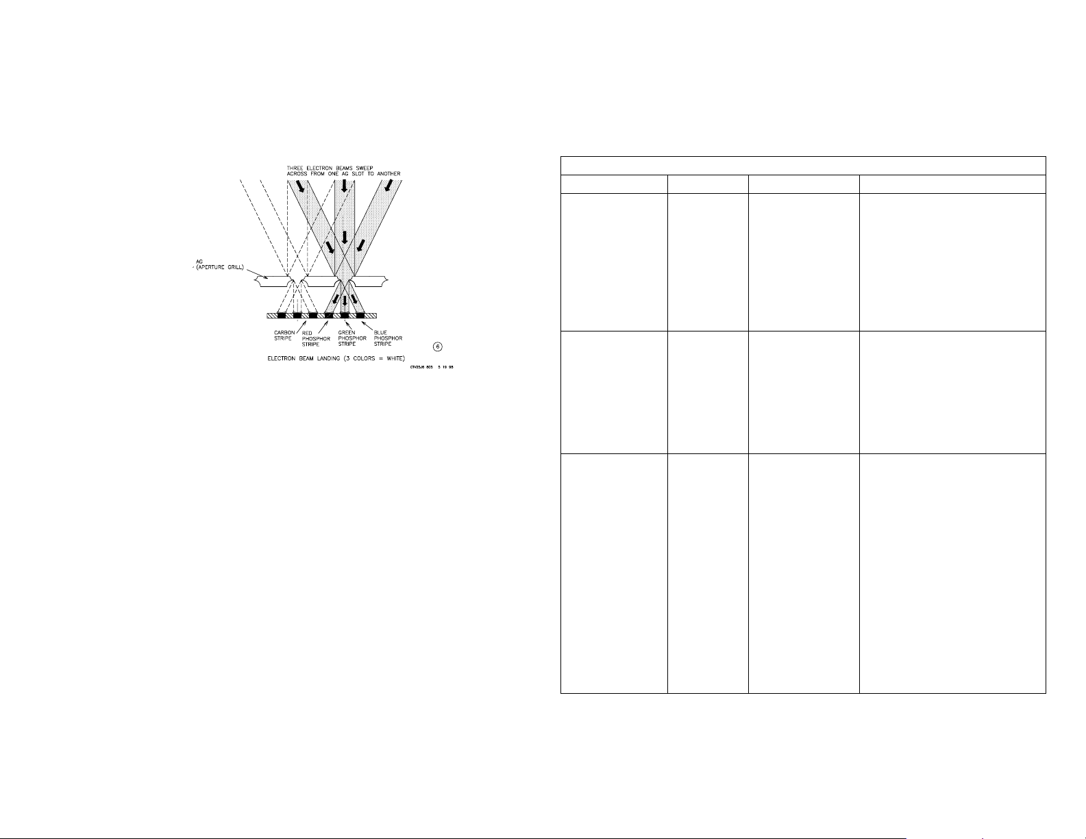
Aperture Grill Purpose
In diagram 5, the slits in the aper-
ture grill allow the electron beam to
pass through and land on the phosphor. The electron beam meant to
land on the green phosphor is
shown:
8
9
In diagram 6 you can see the slits have a more important purpose. When
all three beams are turned ON, the narrow AG slots prevent adjacent
electron beams from landing on the wrong color phosphor. The aperture
grill slots only allow electron beams to pass through and land on their
corresponding color phosphor.
Phosphor Stripes
Phosphor is a powder that becomes luminescent when bombarded by
electrons. The color and persistence of phosphor glow after electron
bombardment is determined by using additional chemicals combined with
the phosphor. Three different color phosphors are painted in vertical
strips that correspond to aperture grill slits. The phosphor strips are separated by carbon stripes that do not glow when struck by electrons. These
carbon stripes allow for manufacturing tolerances when making the AG
and painting the phosphor stripes.
Getter Assembly
Electron emission efficiency and cathode life are greatly dependent upon
a clean environment inside the CRT. After the air is pumped out of the
CRT and sealed, residual water vapor, carbon dioxide and oxygen inevitably remain.
A small cup attached to the gun assembly containing a barium compound is placed inside the picture tube. After sealing the glass picture
tube, the Getter is ”flashed” with a high level of RF energy. The barium
compound heats up and evaporates, combining with the residual undesirable elements in the picture. The resultant compounds that are created coat the inside walls of the picture tube without consequence. The
result is a longer tube life because of the cleaner environment.
Picture T ube Defect Symptoms
Several problems can occur in new picture tubes. The bench technician
can solve some problems and avoid a picture tube replacement.
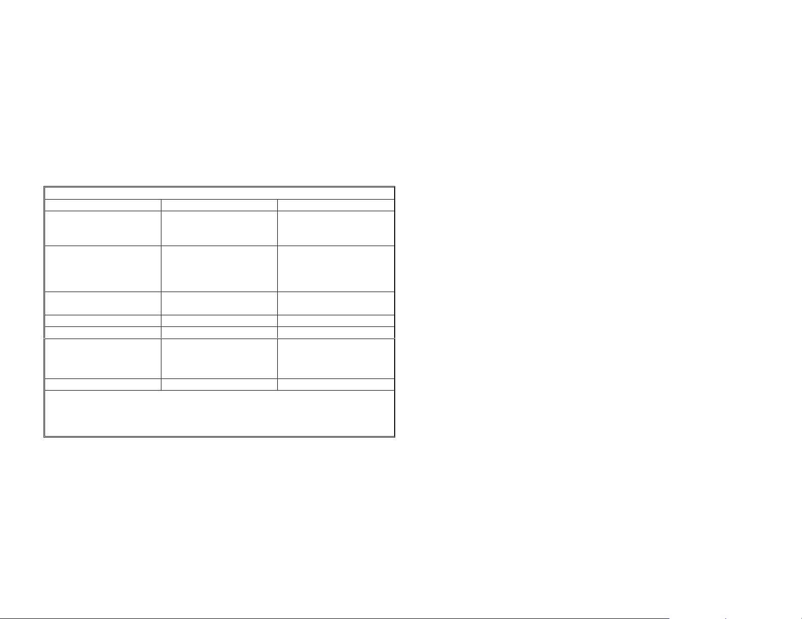
Defective P icture Tube Sym p tom s
Symptom Suspect Check Procedure
Dark picture
or on e color
missing.
Dark picture Grid 1 to
Bright red,
green or blue
picture
One color
retrac e lines
may be
present.
Ret rac e lines
are diag on al
lines th at ru n
fro m lower
left to the
upper right
corner.
Heaters
Open
Grid 2
short.
Heater –
Cathode
short.
OR
Cathode
to G rid 1
short.
A pp ly 6Vd c to
the he ater
term inals.
S ome heat ers
are c onn ec ted
in p arall el,
othe rs in
series but all
take 6Vdc.
Th er e sh ou ld
be in finite
resistan ce
between the
G1 and G2
pins.
Remove th e
R, G or B
vide o outp ut
transistor of
that bright
color. If that
co lor is s till
bright, the
tube is bad.
Th er e sh ou ld
be in finite
resistan ce
between any
CRT pin to
either He ate r
pin. *
Clean the CR T pins and
exam ine t he s ock et for
corrosion.
A pp ly 6Vd c to the C R T
heater pins, looking for a
glow in all 3 heat ers.
Th en if a heat er(s ) do es
not g low , rep lac e th e
picture tube.
1. Unplug TV and
remov e vid e o b oard .
2. Apply 15-20Vdc
between the G 1 and
G 2 p ins to vaporize
the sh ort. Current
lim it the power su p p ly
to 1 Amp.
1. Unplug TV & remove
the video bo ard.
2. Apply 15-20Vdc
between the pins that
show resistance to
vaporiz e the sh ort. *
Cu rrent lim it the
external pow er sup ply
to 1 Amp.
10

11
a
N
Defective Picture Tube S ym ptom s
Sym ptom Suspect Check P rocedure
Bright picture
w ith re trac e
lines and/or
poor foc us.
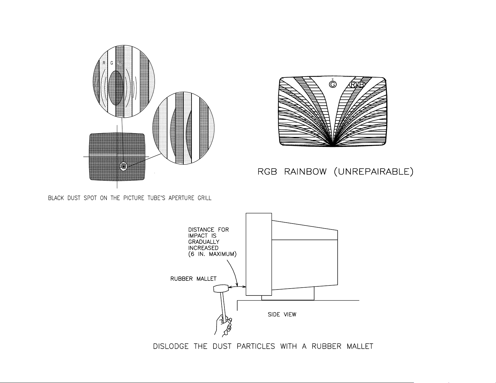
B lac k spot on
the screen .
(see black
spot
diagram )
RGB
Rainbow.
(se e r ain b ow
picture)
P u rity / B e a m
landing is off.
Grid 2 to
high
voltage
Grid 3
l eakage.
Dust
lo dg e d in
the
aperture
g rill.
Aperture
g rill w a s
unseated
in tra ns it.
The TV ’s
degaussi
ng circuit
did not
dem agne
tize
ap ertu re
g rill m e ta l
support.
Symptom is
th at all thre e
colors are
bright.
Generate a
w hite raster.
In sp ec t grill
with
m agnifying
glass.
Rainbow of
colors can
start at the
top or b o ttom
(b ottom
rain b ow
show n).
Sam e color
blotch es
rem ain at that
area of the
screen
reg a rdl es s o f
picture screen
changes.
Reduce G 2 / screen
voltage to the low est
se tting .
V ary foc u s c on trol to b oth
lim its se v era l tim es .
P u t on s a fety a pp a rel.
P lac e the tube face d ow n
and lightly tap the neck to
dislod ge the p article.
M ark location and pull
TV. Follow safety
instruction s.
Apply light im pact w ith
rubber m allet (see
diagram ).
A lo o s e a p e rt u re g rill is
dangerous and m ay
cause tube im plosion.
U se a ll safe ty
precau tions. Do n ot jar
se t. T ran sp ort fac e
down,.
Do not m anually
Degauss the picture
tube with your strong
degaussing coil **.
R e p a ir th e T V ’s
degaussing circuit. The
therm istor is usually at
fa ult.
* Only the heater pins sh ould have resistance. A ll other pins have
infinite (∞ ) resistance to each other and to eith er heater pins.
H ighly-used pictu re tubes th at hav e a he ater-cath od e leak age/s hort
h av e a lo w re st o ra tion s uc cess lev e l.
** Do not m anually Degauss. New 27’ – 35” picture tubes are
m agnetically “conditioned” for optim um beam landing. S trong manu
degaussing w ill destroy this conditioning. Applying disc magnets (P/
= 1-452-094-00) to the bell of the picture tube is the only w ay to
com pensate for lost m agnetic conditioning. The Sony manual
degaussing tool can be used to degauss these tubes because of the
reduced field intensity (P/N = 7-700-781-01).
12
13
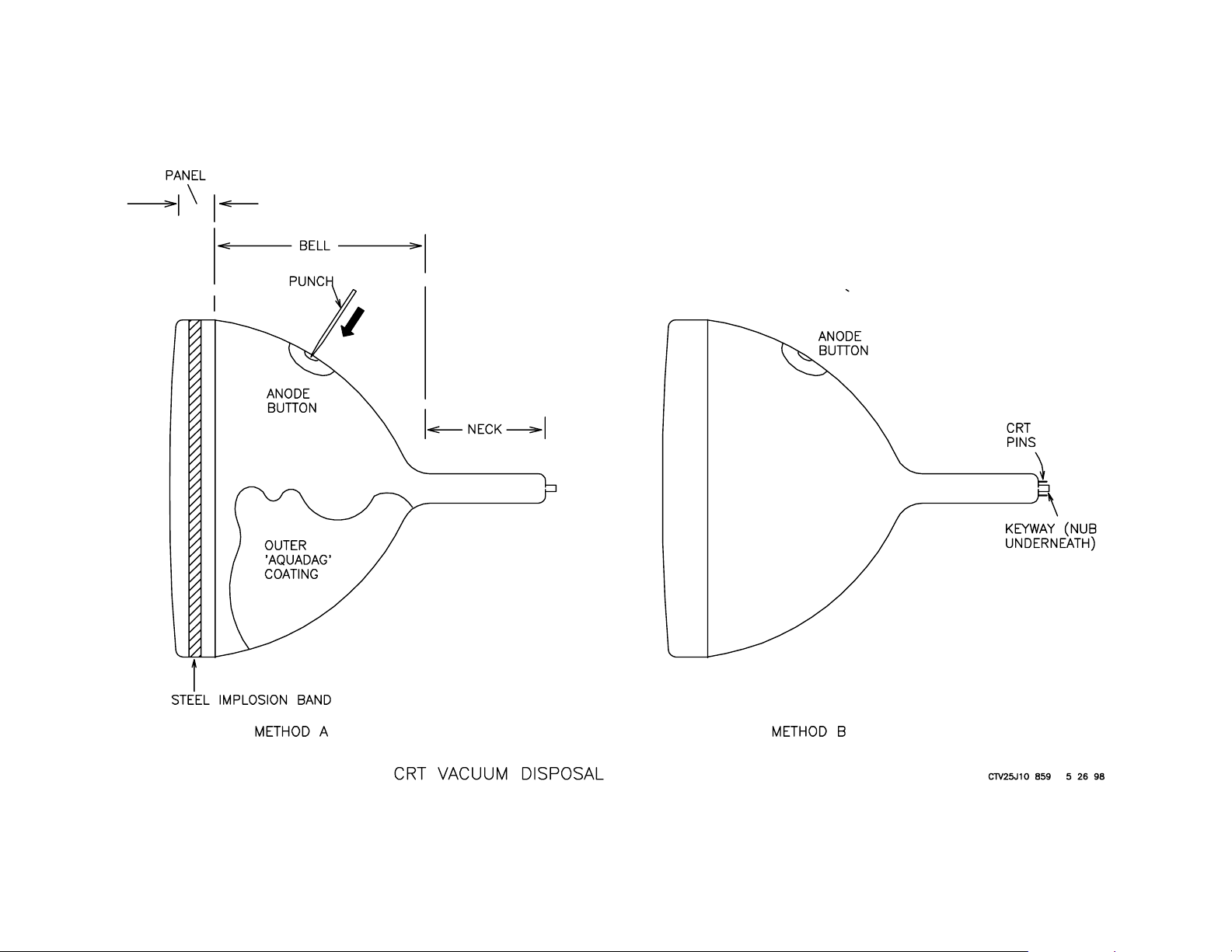
Picture Tube Handling and Vacuum Disposal
Once you have determined that the CRT is inoperative, air should be let
into the tube. This will reduce the risk of implosion caused by a sudden
loss of vacuum.
There are two good methods of “airing” the tube:
A. Puncture through the anode button.
B. Break the thin glass seal at the neck.
The first method allows air to enter the tube gradually.
A. Puncture through the anode button.
Air can be let in gradually by making a hole inside the high voltage anode. The anode is located at the stronger bell part of the picture tube.
Read the procedure below first:
1. Put on protective goggles, gloves, apron and shoes as specified in
the picture tube safety precautions.
2. Check that there is still a steel implosion protection band about the
panel of the 27” or larger picture tubes. See the picture for the location. If it is not present, do not air the tube. Call for professional
disposal.
3. Next, the high voltage stored by the picture tube must be discharged.
The picture tube capacitor has two plates. One plate is inside, connected to the HV anode button. The other plate is outside, connected to ground. The tube’s outside conductive plate is a black
graphite “aquadag” coating. Use a high voltage probe (self
contained)to gradually discharge the high voltage (HV) with the TV
off.
4. Clip one end of a jumper wire to the chassis strap resting on the
conductive black aquadag coating of the picture tube bell. Connect
the other end of the jumper wire to the anode terminal. Leave the
jumper there for about a minute to make sure the picture tube capacitor is completely discharged. During this time, inspect the bottom
area of the picture tube to make sure the ground strap is touching the
black aquadag coating.
5. Using a small screwdriver or center punch as a puncturing tool, seat
it into the center of the soft lead anode button cavity (hole). The
puncturing tool must be able to pass through the anode hole and not
touch the anode button’s outer metal rim.
6. Being careful not to hit the glass with the hammer, gently tap the tool
further into the anode button. The anode is made of a soft lead
amalgam that will give inward.
7. The hissing sound when the punch is wiggled out means that the
tube is “aired”.
B. Break the thin glass seal at the neck.
Method B for releasing the picture tube vacuum is to break the glass nub
at the neck of the tube.
1. Put on protective goggles, gloves, apron and shoes as specified in
the picture tube safety precautions.
2. Check that there is still a metal implosion protection band about the
panel of the 27” or larger picture tubes. If the band has been removed, do not proceed with this vacuum disposal procedure.
3. There is a plastic keyway at the pins of the CRT. Remove the plastic
keyway by wiggling it off. This exposes the glass nub that was sealed
to maintain the vacuum.
4. With a pair of long nose pliers or diagonal cutters, break this glass
nub by squeezing it to shatter the glass. The tube is “aired”.
Read the procedure below first:
Picture Tube Safety Precautions
W ear safety goggles even over glasses to prevent side
•
glass entry
Han dl e t he pi ct ur e tu be wi th t he c orr ect si ze w ork glov es
•
for your hands to avoid slipping
Change to a thic k long sleeve shirt to avoid exposing your
•
skin to glass fragments
W ear a thick rubber apron
•
Wear shoes to protec t your feet
•
Find a partner to help move or reposition the picture tube.
•
Your partner need s protect ive gear more than you do
14

Overall Block Diagram
A TV set consists of several stages or blocks:
15
the last station viewed and the Jungle IC is instructed to select the last
video input used before the set was turned OFF.
The communications data and clock lines are always active when the TV
is ON.
• Power Supply
• Power On/Communications
• Video Processing
• Deflection
Each stage has a purpose and is activated in sequence to properly power
up the set.
Power Supply
The purpose of the power supply is to convert the incoming 120Volts AC
to some of the DC voltages required to operate the set, the most important of which is the Standby +5Vdc. Standby +5Vdc is present when the
set is plugged in and is used to power the Micro so it can respond to a TV
power ON command from the user.
Power On/Communications
Three things occur when the power button is pressed:
• Degaussing of the picture tube
• Application of power to the Jungle IC
• Data communications
When the TV is powered ON, the Micro turns ON the degaussing circuit
for 2.2 seconds. Its purpose is to pass AC through the degaussing coil
that surrounds the picture tube. The AC field that is created erases residual magnetism collected by the tube’s metal aperture grill.
Next the Micro IC turns the TV ON switching power from the power supply to the Y/C Jungle IC. The Jungle IC produces vertical (VD) and horizontal (HD) pulses to create the remainder of the voltages necessary for
the TV to operate. This turns ON the TV (see Deflection).
After the TV turns ON, data and clock communications from the Micro IC
are applied to the tuner and Jungle IC. The tuner is instructed to tune to
Video Processing
The Y/C Jungle IC selects a video signal from one of two external video
inputs or the internal tuner video for processing. Contrast, brightness,
color level and hue are also controlled in this IC. A change in level is
received by the Micro IC, stored in memory , and communicated to this Y/
C Jungle IC thorough the data and clock inputs. The final stage within
this IC converts the information to individual red, green and blue (RGB)
output voltages. The higher the voltage, the greater the intensity of that
color. The three RGB voltages are applied to the video output stage.
The purpose of the video output stage is twofold:
1. To invert the signal
2. To convert the small red, green and blue input voltages to larger voltages for the picture tube drive
The voltage output of this video stage is applied to the picture tube cathodes. This voltage varies from 200 volts for a dark picture to zero volts
for a very bright picture.
Deflection
When the Y/C Jungle IC receives power and serial data, its internal vertical and horizontal oscillators operate and output. These two VD and
HD signals leave the IC to drive the external deflection amplifiers. The
output of the vertical deflection stage drives the vertical deflection coil of
the yoke. The purpose of the vertical yoke coil is to move or “sweep” the
picture tube’s electron beam downward to produce the picture.
The yoke and flyback transformer (FBT) use the output of the horizontal
deflection stage. The yoke uses this drive signal in the horizontal deflection coil to sweep the electron beam from left to right and back (retrace)
to produce the picture.
The flyback transformer is a low current high frequency transformer
that develops the remainder of the voltages the TV set needs to operate.

16

17
Power Supply Block – 20” TV & smaller
In the smaller BA-4 chassis TVs, power is applied to most of the TV
stages when the set is plugged into 120Volts AC. Three stages develop
and regulate the four voltages that leave the power supply:
1. The converter stage
2. The voltage output stage
3. The power output control
The Converter Stage
The purpose of the converter stage is to change the low frequency (60Hz)
AC that is input to this stage into a high frequency AC signal that will
output this stage. To do this, several operations take place within the
converter stage:
• The 120Volts AC input is rectified into DC and filtered.
• This DC voltage powers a medium power, high frequency oscillator.
An oscillator is used in this converter stage because its frequency is
easily controllable and the high frequency output can pass through a
small lightweight transformer. This keeps the entire TV lightweight
and efficient.
• The high frequency AC output of the oscillator is applied to the next
stage for multiple voltage outputs.
The voltage output stage
The purpose of this voltage stage is to provide multiple voltages to the
TV. The oscillator signal from the converter stage is applied to a transformer in the voltage output stage. The transformer’s secondary windings are used to make the four voltages. The most important voltages
are the standby +5V and the B+ voltage. In the 13” and 20” BA-4 chassis, the B+ is +116Vdc. In the 27” TV, B+ equals +135Vdc.
The power output control.
The purpose of this stage is to maintain/regulate the B+ voltage. The
input to the power control stage is the B+ voltage. Variations in the B+
voltage will change the converter’s oscillator frequency.
Transformer Operation Point
Increasing the oscillator frequency results in a shift along the transformer’s
resonate frequency curve. This results in a decrease in the transformer’s
primary to secondary transfer efficiency. Therefore, there is reduced
secondary output until the B+ has returned to normal.
Conversely , decreasing the oscillator frequency simultaneously increases
the four voltages that leave the voltage output stage. In this power control circuit, the oscillator frequency stops changing when B+ has returned
to +116Vdc or 135Vdc (depending upon the set size). This is how the
power output control stage regulates the four voltages that leave the
power supply.
• The standby +5V is used to power the microcomputer.
• The (B+) is used to power the horizontal deflection and high voltage
stages. Variations in the B+ voltage will cause the picture to change
in width and brightness.

18
19
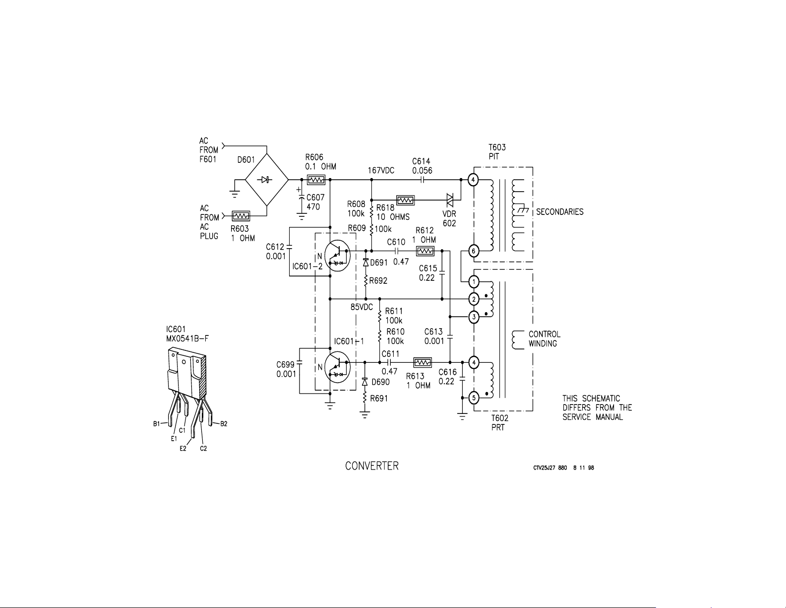
Converter
In the past, the word “converter” referred to a rotating machine consisting of an electric motor driving an electric generator. This system was
used to change alternating current into direct current. Changing AC to
DC is also the purpose of this converter, but it is done in an electronic manner .
The converter consists of two parts:
1. The Rectifier
2. The Oscillator
Rectifier
The rectifier changes the 120Volts AC into DC using bridge rectifier D601.
The output of D601 is a pulsating DC waveform commonly called the
ripple. The 60 Hz ripple has a crest (high point) and a trough (low point).
C607 is the main filter capacitor that reduces the ripple amplitude by
charging during a crest and discharging to fill a void during the trough.
However, as the TV’s current demand increases, C607 cannot supply
the additional current to the TV during the trough. This is why there is a
higher AC ripple across the filter capacitor during a bright scene when
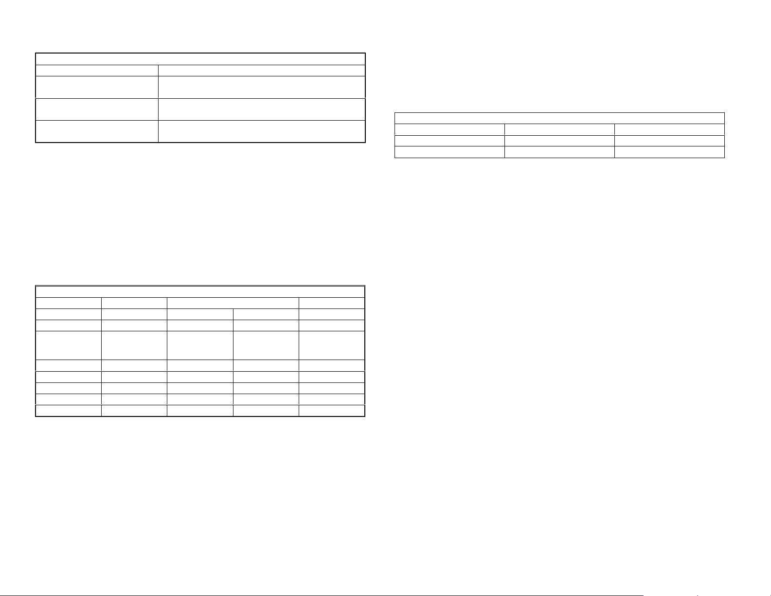
there is a greater current demand. This is shown in the chart below:
60 Hz Ripple at Main Filter Capacitor C607
TV Set OFF 0.8Vp-p across C607
TV Set ON – Dark screen 4Vp-p across C607
TV Set ON – Bright screen 6Vp-p across C607
Oscillator
The oscillator consists of two transistors, a main transformer, a PR T power
regulator) transformer (PRT)bias and protection resistors and capacitors.
When the oscillator runs, it produces a 180Vp-p square wave into the
main Power Input Transformer (PIT) T603/pin 6. The two transistors
(IC601) alternately turn ON and OFF to develop the square wave. The
operation of the oscillator consists of three parts:
1. A quiescent state
2. When the bottom transistor is ON and the top is OFF
3. When the bottom transistor is OFF and the top is ON
The Quiescent State
The oscillator starts when DC voltage from fusible resistor R606 is applied to the oscillator stage. Two initial current paths are taken toward
ground within the oscillator stage. The first current path places both
transistors in the IC601 package at the threshold of conduction to establish a quiescent state. This state places 85Vdc at IC601/2’s emitter.
First Current Path to Ground
Component Input Output
R606
R608 & R609 R608 R609
IC601-2 Base Emitter
IC601-2 Collector Emitter
R611 & R610 R611 R610
IC602-1 Base Emitter / Ground
IC602-1 Collector Emitter / Ground
Resistors R608, R609, R61 1 and R610 form a voltage divider string from
the +167Vdc supply to ground. The base – emitter junction of IC601/2
connects resistors R609 and R611. R610 is connected to ground by the
base – emitter junction of IC601/1.
The voltage at the junction of R609 and R611 is approximately half the
supply voltage because the resistors in the voltage divider string are the
same value. Therefore,
before oscillation begins, there are 167Volts/2 =
83.5Vdc at IC601/1’s collector. At this time, the TV set consumes 40ma
AC (C614 removed to stop oscillation).
Bottom Transistor IC601-1 Turns ON
The second current path turns OFF transistor IC601-2 and turns ON transistor IC601/1, beginning the oscillator operation. This path passes
through several parts to ground:
Second Current Path to Ground
Component Input Output
R606
C614
T603 PIT Pin 4 Pin 6
T602 PRT Pin 1 Pin 2
R611 & R610 R611 R610
IC601-1 Base Emitter / Ground
IC601-1 Collector Emitter / Ground

20
21
A magnetic field is created when current flows through pins 1-2 of PRT
transformer T602. This induces a negative voltage that outputs the transformer at T602/pin 3. This negative voltage is applied to the base of
IC601-2, turning it OFF.
At the same time, a positive induced voltage from T602/pin 4 is applied
to the base of IC601-1. This voltage is held there by capacitor C616 and
coupled to the base via C611. The positive voltage drives IC601-1 into
saturation (ON). The voltage at the collector of IC601-1 becomes zero
by transistor action. This zero volts also appears at T603/pin 6 because
the inductance of T602 is small (few windings).
Because C614 initially acts like a momentary short, the full +167 supply
voltage is applied to T603’s primary transformer windings (pins 4-6).
T603’s rising magnetic field is coupled into the secondary windings.
Top Transistor IC601-2 Turns ON
The conduction of the transistors in the IC601 package alternate when
the magnetic field in T603 collapses. Eventually, C616’s charge leaks
off so IC601-1 can no longer be held in conduction. At this time current
stops flowing through IC601-1 and PIT T603’s primary winding. The
magnetic field that is built up in the primary winding of T603 now collapses and current through the primary winding of T603 flows in the opposite direction. During the collapsing magnetic field, current takes this
path through IC601-2:
Collapsing Magnetic Field Current Path
Component Input Output
T603/pin 4
C614
R608 & R609 R608 R609
IC601-2 base Emitter
IC601-2 collector Emitter
T602 pin 2 Pin 1
T603/pin 6
Both IC601 transistors receive a change in base bias. While current is
flowing through T602/pins 2-1, a positive voltage is induced and output
T6502/pin 3. This is coupled into the base of IC601-2, turning it ON. At
the same time, a negative voltage is induced and output T602/pin 4.
This turns IC601-1 OFF. As a result of IC601-2’s conduction, its emitter
rises to 167Vdc.
When the collapsing magnetic field in T603 has depleted its energy, the
cycle repeats, starting with the charging of C614. The result is a square
wave at the junction of the two IC601 transistors when they alternately
turn ON and OFF.
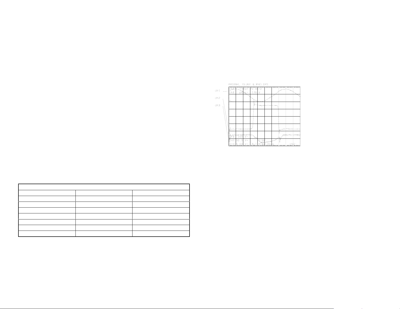
The following waveform shows the oscillator’s square wave output (channel 2) at IC601. It is shown with IC601-1 base bias (channel 3) and the
sine wave at the junction of transformer T603 and C614 (channel 1).
Oscillator Stage. TV = ON, 120Vac input.
Channel 1 – T603/pin 4; 50V/div.
Channel 2 – IC601-1 Collector; 50V/div.
Channel 3 – IC601-1 Base; 5V/div.
Time base = 2usec/div.
Oscillator Stage Protection
Protection 1 – VDR602
All of the TV’s power comes through C614 and T603. A bright scene
accompanied by a surge in AC line can pass more current through C614
than normal. More current means there would be a greater voltage drop
across C614. If the capacitor’s maximum voltage is exceeded, it will
short and damage the transformer. VDR602 is placed across C614 for
its protection. VDR602 is a Voltage Dependant Resistor that only shows
low resistance when there is a high voltage across it. When good, it
measures like a small capacitor.
22

23
Protection 2 – D690 & D691
The oscillator transistors (IC601) are protected from a base to emitter
failure. A transistor’s base to emitter junction can be punctured (open) or
shorted. By applying an 8-10 volt reverse (b-e) bias voltage from a collapsing magnet field to this junction, the transistor will short. C615, C616
and C613 prevent sharp (high voltage) spikes from leaving the transformer. Diodes D690 and D691 prevent the transistor’s base to emitter
junction from being reversed.
Protection 3 – C612 & C699
A transistor’s collector to emitter junction can be shorted if the maximum
voltage across these terminals is exceeded (Vce). Although the typical
maximum voltage for these transistors is 600volts, it can still be exceeded
when lightning brings in a much higher voltage. The voltage spikes from
a non-direct lightning hit may be high in voltage, but low in current (small
pulse width). They are bypassed to ground with C612 and C699. If a
very high current spike shorted IC601-2 from collector to base, current
would also have flowed through C610 and R612 and they should be
replaced.
IC601 Protection
Protection from internal
spikes causing immediate
failure.
Protection from external
spikes (lightning).
Protection - Thermal R606 (fusible resistor).
D690/D691 – prevents
IC601’s E-B junction
from reverse bias damage
C612/C699 –high voltage low current spikes are
circumvented by this capacitor. This reduces the
voltage to IC601 so the transistor’s C-E breakd own
voltage specification is not exceeded.
C615/C616/C613 –
rounds off sharp spikes
from rising and collapsing
magnetic fields.
Oscillator Frequency
The oscillator frequency is predominately a function of T603 inductance
and C614 capacitance, forming a sine wave at the junction. Since the
inductance of T603 is changed with a load, the frequency of the oscillator will be different when the set is turned ON.
O s c illa tor C h a ra c te ris tic s
Resonate parts: L = T603 (uH) C = C 610, C611, C614,
Frequ ency: 104kHz.
T V O F F (no load)
C615, C616
71.5kH z.
TV O N
Oscillator Testing
After replacing parts in this stage, check the following with an ohmmeter
before gradually applying power:
• Shorts in T603 secondary winding loads (secondaries). Check zener
diode D610 first (see Converter Voltage Output diagram below)
• Shorts in a flyback secondary winding loads
Testing Procedure Steps:
1. Plug the set into an
an AC ammeter and voltmeter) and set to zero volts AC.
2. Unplug the degaussing coil so the AC ammeter will only show the TV
current consumption.
3. Gradually increase the AC voltage to the TV while observing the following:
• The AC current on the variable AC transformer
• The oscillator supply voltage (DC) at fusible resistor R606
• The DC voltage at the collector of the bottom transistor IC601-1
4. Gradually increase the AC voltage. The DC voltage at the collector
of IC601-1 will always be half that of the oscillator supply voltage at
R606 if the oscillator is OK. This is true at any time, even when the
AC voltage is being increased. The oscillator will start when there is
about 5-6Vdc at R606.
isolated variable AC transformer (must contain

24
25
What to Expect When Increasing the AC Voltage to the TV
Observe: Normal on a 20” BA-4 chassis TV
AC Current (degauss ing coil
unplugged)
Oscillator’s DC supply
voltage at R606
Collector of IC601-1 Must be half the DC voltage measured at R606. If
Current will rise to 1 amp at about 12Volts AC, then
drop down to 0.34Amps
Will increase proportional to the AC voltage being
increased.
not, a pa rt is still defec tive.
Normal Testing Results
Below is a chart that shows the converter/TV operation as AC is increased
slowly to the TV that is OFF. The Degaussing coil is unplugged during
this test.
In the 27” BA-4 chassis, the converter can be tested by temporarily jumping the TV’s ON/OFF relay contacts and removing the load by unsoldering
a series inductor L504. Do not disconnect the B+ regulating stage (IC603,
DM-58) or the TV will draw an abnormally high current as the AC voltage
is increased.
Increasing Voltages with TV OFF – Model KV20M40
Converter IC601-2/E
AC DC at R606 Vp-p Freq. B+
7 Vac 8 Vdc 20 Vp-p 55kHz 22Vdc
11 Vac 11 Vdc 28 Vp-p (w
spikes)
49kHz 108Vdc
When beginning to increase the AC voltage to the set under test, the AC
current will increase sharply until the B+ reaches the correct voltage for
that set (116Vdc or 135Vdc) and then drops gradually as AC voltage is
increased. The degaussing coil is unplugged during this test.
Peak AC Current Consumption
Model AC Voltage AC Current
KV20M40 12Vac 0.8 Amps
KV27S45 11Vac 1.3 Amps
Above 12Vac, the B+ has reached its maximum and the regulation stage
changes the converter frequency to supply sufficient TV current to maintain a steady B+ voltage. As the input AC is being increased toward
120Vac, the current continues to drop toward the normal operating level.
This TV power supply can run unloaded, but the regulation circuit must
remain intact or the unit will damage the converter IC601 and blow a
fuse.
22 Vac 25 Vdc 35 Vp-p 51kHz 116Vdc
40 Vac 50 Vdc 60 Vp-p 54kHz 116Vdc
75 Vac 100 Vdc 100 Vp-p 61kHz 116Vdc
110 Vac 150 Vdc 150 Vp-p 78.5kHz 116Vdc
120 Vac 166 Vdc 170 Vp-p 104kHz 116Vdc

26
 Loading...