

Sony BRC-H900 User Manual

A-E99-100-11 (1)
HD Color Video Camera
Command List
Version 1.00
BRC-H900
© 2012 Sony Corporation

Table of Contents
VISCA RS-232C/RS-422 Commands .................. 3
Overview of VISCA ........................................... 3
VISCA Communication Specifications ............. 4
VISCA Device Setting Command ..................... 6
VISCA Command/ACK Protocol ...................... 7
VISCA Camera-Issued Messages ...................... 8
BRC-H900 Commands ......................................... 9
BRC-H900 Command List (1/5)........................ 9
BRC-H900 Command List (2/5)...................... 10
BRC-H900 Command List (3/5)...................... 11
BRC-H900 Command List (4/5)...................... 12
BRC-H900 Command List (5/5)...................... 13
BRC-H900 Inquiry Command List (1/3) ......... 14
BRC-H900 Inquiry Command List (2/3) ......... 15
BRC-H900 Inquiry Command List (3/3) ......... 16
BRC-H900 Block Inquiry Command List ....... 17
VISCA Command Setting Values .................... 25
Pan/Tilt Status Code List ................................. 27
Memory Function (Inquiry Commands) .......... 28
Revision History .................................................. 29
2

VISCA1) RS-232C/RS422 Commands
Use of RS-232C/RS-422 control software based upon
this command list may cause malfunction or damage to
hardware and software. Sony Corporation is not liable
for any such damage.
Overview of VISCA
In VISCA, the side outputting commands, for example,
a computer, is called the controller, while the side
receiving the commands, such as a BRC-H900, is called
the peripheral device. The BRC-H900 serves as a
peripheral device in VISCA. In VISCA, up to seven
peripheral devices like the BRC-H900 can be connected
to one controller using communication conforming to
the RS-232C/RS-422 standard. The parameters of RS232C/RS-422 are as follows.
• Communication speed: 9600 bps/38400 bps
• Data bits : 8
• Start bit : 1
• Stop bit : 1
• Non parity
Flow control using XON/XOFF and RTS/CTS, etc., is
not supported.
Note
In the same network, all the camera address selectors
should be set to “0” (automatic setting) or all the
selectors should be manually set to “1” to “7”. Do not
mix the automatic and manual settings.
Each VISCA equipment has VISCA IN and VISCA
OUT connectors.
Set the DTR input (the S output of the controller) of
VISCA IN to H when controlling VISCA equipment
from the controller.
Fig. 1 VISCA network configuration
VISCA Controller
VISCA Equipment
IN
OUT
IN
OUT
Peripheral devices are connected in a daisy chain. As
shown in Fig. 1, the actual internal connection is a onedirection ring, so that messages return to the controller
via the peripheral devices. The devices on the network
are assigned addresses.
The address of the controller is fixed at 0.
The addresses of peripheral devices are as follows.
When the camera address selector is set to 0
(automatic setting mode)
The peripheral devices are assigned to the addresses, 1,
2, 3… in the connected order, starting from the one
connected nearest to the controller. These addresses are
set when the controller sends address commands during
initialization of the network.
When the camera address selector is set to 1
through 7 (manual setting mode)
The addresses of the peripheral devices will be set to the
pre-selected numbers. Within a single system, the same
number can be used only once. If an address selector
number other than 0 is used, set the camera address
selectors on the connected BRC-H900 cameras to
different numbers.
IN
OUT
............................................................................................................................................................................................................................
1) VISCA is a protocol developed by Sony for controlling a consumer’s camcorder. “VISCA” is a trademark of Sony Corporation.
3
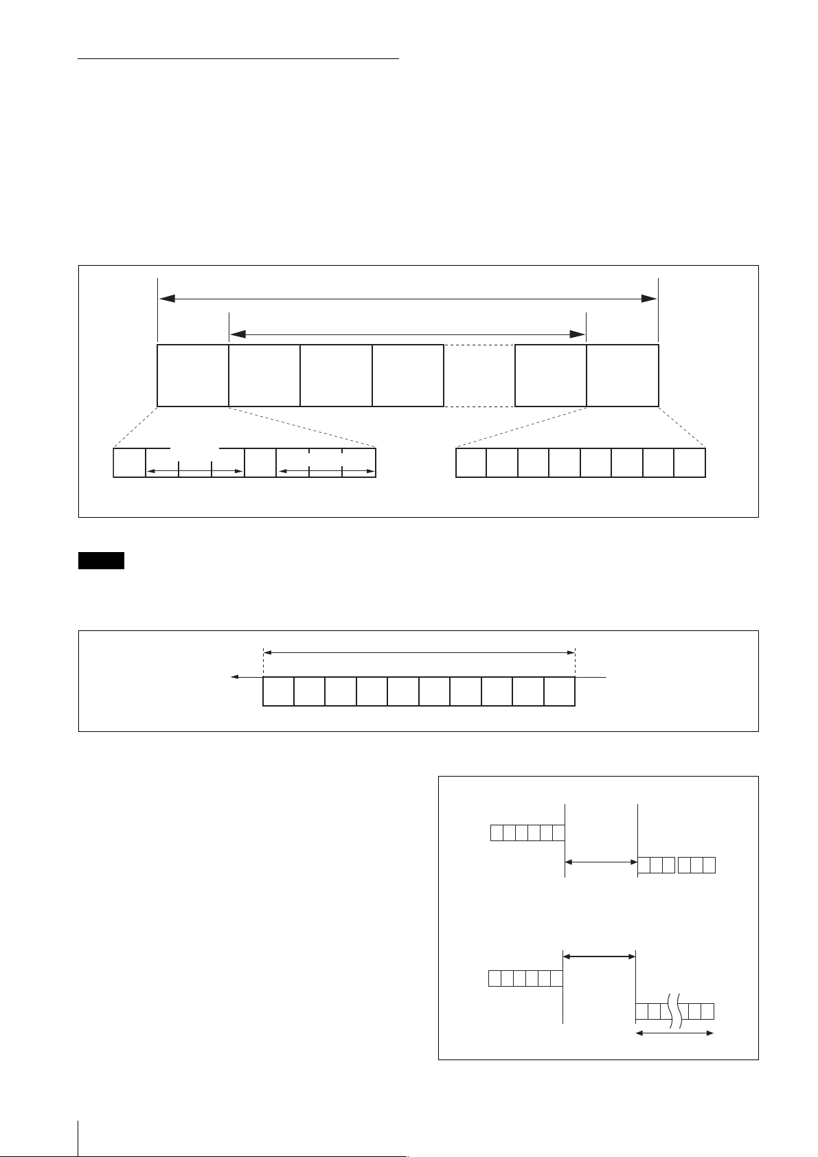
VISCA Communication Specifications
VISCA packet structure
The basic unit of VISCA communication is called a
packet (Fig. 2). The first byte of the packet is called the
header and comprises the sender’s and receiver’s
addresses. For example, the header of the packet sent to
the BRC-H900 assigned address 1 from the controller
(address 0) is 81H in hexadecimal. The packet sent to the
Packet (3 to 16 bytes)
BRC-H900 assigned address 2 is 82H. In the command
list, as the header is 8X, input the address of the BRCH900 to X. The header of the reply packet from the
BRC-H900 assigned address 1 is 90H. The packet from
the BRC-H900 assigned address 2 is A0H.
Some of the setting commands for BRC-H900 can be
sent to all devices at one time (broadcast). In the case of
broadcast, the header should be 88H in hexadecimal.
When the terminator is FFH, it signifies the end of the
packet.
Header Terminator
Byte 1 Byte 2 Byte 3
Sender’s
10
Bit 7
(MSB)
Note
address
Bit 6 Bit 5 Bit 4 Bit 3 Bit 2 Bit 1 Bit 0
Receiver’s address
Message (1 to 14 bytes)
(LSB)
Fig. 2 Packet structure
Fig. 2 shows the packet structure, while Fig. 3 shows the
actual waveform. Data flow will take place with the LSB
first.
Start
Bit 0 Bit 1 Bit 2 Bit 3 Bit 4 Bit 5
bit
(LSB) (MSB)
1 byte
FF
11111111
Bit 7
Bit 6 Bit 5 Bit 4 Bit 3 Bit 2 Bit 1 Bit 0
(MSB)
Bit 6 Bit 7
Stop
bit.
(LSB)
Fig. 3 Actual waveform for 1 byte.
Timing Chart
As VISCA command processing can only be carried out
a maximum of one time in a Vertical (V*) cycle, it takes
maximum 4V-cycle time for an ACK/Completion to be
returned.
If the Command and ACK/Completion communication
time is shorter than 1V-cycle time, a command can be
received at every 1V cycle. From this point, if two or
more commands are to be sent successively, wait for a
reply command (an ACK or error message for a general
command, and an inquiry packet for an inquiry
command) of the previous command to be received
before sending the next command.
*1V=16.7 msec (NTSC, 1080/59.94i, 720/59.94p), 20 msec (PAL, 1080/
50i, 720/50p)
4
General commands
Command
RxD
TxD
Inquiry commands
Command
RxD
TxD
ACK Completion
Within 4V
Within 4V
Inquiry Packet
16 Bytes

Command and inquiry
• Command
Sends operational commands to the BRC-H900.
• Inquiry
Used for inquiring about the current state of the BRCH900.
Command Packet Note
Inquiry 8X QQ RR ... FF QQ1) = Command/Inquiry,
1)
QQ = 01 (Command), 09 (Inquiry)
2)
RR = 00 (Interface), 04 (camera 1), 06 (Pan/Tilter)
X = 1 to 7: BRC-H900 address
2)
= category code
RR
For actual values to be sent, see Command Lists or
Inquiry Command Lists.
Responses for commands and inquiries
• ACK message
Returned by the BRC-H900 when it receives a
command. No ACK message is returned for an
inquiry.
• Completion message
Returned by the BRC-H900 when execution of
commands or inquiries is completed. In the case of
inquiry commands, reply data for the inquiry is
contained after the 3rd byte of the packet. If the ACK
message is omitted, the socket number will contain 0.
Reply Packet Note
Ack X0 4Y FF Y = socket number
Completion (Commands) X0 5Y FF Y = socket number
Completion (Inquiries) X0 5Y ... FF Y = socket number
X = 9 to F: BRC-H900 address + 8
• Error message
When a command or inquiry command could not be
executed or failed, an error message is returned
instead of a completion message.
Error Packet Description
X0 6Y 01 FF Message length error
X0 6Y 02 FF Syntax Error
X0 6Y 03 FF Command buffer full
X0 6Y 04 FF Command canceled
X0 6Y 05 FF No socket (to be canceled)
X0 6Y 41 FF Command not executable
X = 9 to F: BRC-H900 address + 8, Y = socket number
Socket number
When command messages are sent to the BRC-H900, it
is normal to send the next command message after
receiving the completion message or error message.
However, to deal with advanced uses, the BRC-H900
has two buffers (memories) for commands, so that up to
two commands including the commands currently being
executed can be received. (There is a wait longer than a
1V cycle between commands.) However, depending on
the command, it may be necessary to wait until the first
command is completed. When the BRC-H900 receives
commands, it notifies the sender which command buffer
was used, using the socket number of the ACK message.
As the completion message or error message also has a
socket number, it indicates which command has ended.
Even when two command buffers are being used, a
BRC-H900 management command and some inquiry
messages can be executed.
The ACK message is not returned for these commands
and inquiries, and only the completion message of
socket number 0 is returned.
Command execution cancel
To cancel a command which has already been sent, send
a Cancel command as the next command. To cancel one
of two commands which have been sent, use the cancel
message.
Cancel Packet Note
Cancel 8X 2Y FF Y = socket number
X = 1 to 7: BRC-H900 address, Y = socket number
Error message “Command canceled” will be returned
for this command, but this is not a fault. It indicates that
the command has been canceled.
Note
To cancel a command when VISCA PAN-TILT Drive
(page 12) is being executed, wait at least 200 msec after
executing. Then send a cancel command to ensure that
PAN-TILT Drive stops effectively.
To execute a PAN-TILT Drive command again, wait at
least 200 msec after the message “Command canceled”
has appeared.
5

VISCA Device Setting Command
Before starting control of the BRC-H900, be sure to
send the Address command and the IF_Clear command
using the broadcast function.
For VISCA network administration
• Address
Sets an address of a peripheral device. Use when
initializing the network, and receiving the following
network change message.
• Network Change
Sent from the peripheral device to the controller when
a device is removed from or added to the network. The
address must be re-set when this message is received.
Packet Note
Address 88 30 01 FF Always broadcasted.
Network Change X0 38 FF
X = 9 to F: BRC-H900 address + 8
VISCA interface command
• IF_Clear
Clears the command buffers in the BRC-H900.
When cleared, the operation currently being executed
is not guaranteed.
Command Packet Reply Packet Note
IF_Clear 8X 01 00 01 FF X0 50 FF
IF_Clear (broadcast) 88 01 00 01 FF 88 01 00 01 FF
X = 1 to 7: BRC-H900 address (For inquiry packet)
X = 9 to F: BRC-H900 address +8 (For reply packet)
VISCA interface and inquiry
• CAM_VersionInq
Returns information on the VISCA interface.
Inquiry Inquiry Packet Reply Packet Description
CAM_VersionInq 8X 09 00 02 FF Y0 50 GG GG HH HH JJ JJ KK FF GGGG = Vender ID
(0001: Sony)
HHHH = Model ID
0501: BRC-H700
0502: BRU-H700
0505: BRC-Z700
0507: BRC-Z330
050B: BRC-H900
JJJJ = ROM revision
KK = Maximum socket # (02)
X = 1 to 7: BRC-H900 address (For inquiry packet)
X = 9 to F: BRC-H900 address +8 (For reply packet)
6

VISCA Command/ACK Protocol
Command Command Message Reply Message Comments
General Command 81 01 04 38 02 FF
(Example)
81 01 04 38 FF
(Example)
81 01 04 38 02 FF
(Example)
81 01 04 08 02 FF
(Example)
Inquiry Command 81 09 04 38 FF
Address Set 88 30 01 FF 88 30 02 FF The device address number plus 1 is returned.*
IF_Clear
(Broadcast)
IF_Clear (For x) 8x 01 00 01 FF z0 50 FF (Completion) ACK is not returned for this command.
Command Cancel 8x 2y FF z0 6y 04 FF
* When the camera address selector is set to an address other than 0, the value x in 88 30 0x FF will be variable.
(Example)
81 09 05 38 FF
(Example)
88 01 00 01 FF 88 01 00 01 FF The same command is returned.
90 41 FF (ACK)+90 51 FF
(Completion)
90 42 FF 90 52 FF
90 60 02 FF
(Syntax Error)
90 60 03 FF
(Command Buffer Full)
90 61 41 FF
(Command Not Executable)
90 62 41 FF
90 50 02 FF (Completion) Does not return ACK.
90 60 02 FF
(Syntax Error)
(Command Canceled)
z0 6y 05 FF
(No Socket)
Returns ACK when a command has been accepted, or
Completion when a command has been executed.
Accepted a command which is not supported or a command
lacking parameters.
Could not accept the command as there are two commands
currently being executed.
Could not execute the command in the current mode.
Accepted an incompatible command.
Returned when the command of the socket specified is
canceled. Completion for the command canceled is not
returned.
Returned when the command of the specified socket has
already been completed or when the socket number specified
is wrong.
Do not transmit the command (except Address Set,
IF_Clear, Command Cancel, POWER (page 12)) when
any menu is displayed on the screen. If displayed, clear
the menu first using MENU Display OFF (page 13)
Command, and then proceed.
7

VISCA Camera-Issued Messages
ACK/Completion Messages
Command Command Message Comments
ACK z0 4y FF
(y: Socket No.)
Completion z0 5y FF
(y: Socket No.)
z = Device address + 8
Error Messages
Command Command Message Comments
Syntax Error z0 60 02 FF Returned when the command format is different or when a command with
Command Buffer Full z0 60 03 FF Could not accept a command that is received while two commands are
Command Canceled z0 6y 04 FF
(y: Socket No.)
No Socket z0 6y 05 FF
(y: Socket No.)
Command Not Executable z0 6y 41 FF
(y: Socket No.)
Returned when the command is accepted.
Returned when the command has been executed.
illegal command parameters is accepted.
currently being executed (two sockets have been used).
Returned when a command which is being executed in a socket specified by
the cancel command is canceled. The completion message for the command
is not returned.
Returned when no command is executed in a socket specified by the cancel
command, or when an invalid socket number is specified.
Returned when a command cannot be executed due to current conditions.
For example, when a command for controlling the manual focus is received
during the auto focus mode.
Network Change Message
Command Command Message Comments
Network Change z0 38 FF Issued when power is supplied to the camera.
8

BRC-H900 Commands
BRC-H900 Command List (1/5)
Command Set Command Command Packet Comments
EXPOSURE MODE FULL AUTO 8x 01 04 39 00 FF
MANUAL 8x 01 04 39 03 FF
SHUTTER Pri 8x 01 04 39 0A FF
IRIS Pri 8x 01 04 39 0B FF
BACK LIGHT 8x 01 04 33 02 FF Available only when MODE is set to FULL
SPOT LIGHT 8x 01 04 3A 02 FF
IRIS Reset 8x 01 04 0B 00 FF When EXPOSURE MODE is set to MANUAL or
Up (OPEN) 8x 01 04 0B 02 FF
Down
(CLOSE)
Direct 8x 01 04 4B 00 00 0p 0q FF pq: See the VISCA Command Setting Values
SHUTTER Reset 8x 01 04 0A 00 FF When EXPOSURE MODE is set to MANUAL or
Up (HIGH)
Down (LOW) 8x 01 04 0A 03 FF
Direct 8x 01 04 4A 00 00 0p 0q FF pq: See the VISCA Command Setting Values
GAIN Reset 8x 01 04 0C 00 FF When EXPOSURE MODE is set to MANUAL,
Up 8x 01 04 0C 02 FF
Down 8x 01 04 0C 03 FF
Direct 8x 01 04 4C 00 00 0p 0q FF pq: See the VISCA Command Setting Values
AE SPEED Direct
AE LEVEL Reset 8x 01 04 0E 00 FF
Up 8x 01 04 0E 02 FF
Down 8x 01 04 0E 03 FF
Direct 8x 01 04 4E 00 00 00 0p FF p 5: -1.0 6: -0.5 7: 0 8: +0.5 9: +1.0
AGC ON/OFF 8x 01 7E 01 75 0p FF p 2: ON 3: OFF
AGC LIMIT Direct 8x 01 04 2C 0p FF p 0: 3dB 1: 6dB 2: 9dB 3: 12dB 4: 18dB
AGC POINT Direct 8x 01 7E 01 76 0p FF p 0: F5.6 1: F4 2: F2.8
AUTO
SHUTTER
SHUTTER
LIMIT
SHUTTER
POINT
Direct 8x 01 7E 01 77 0p FF p 2: ON 3: OFF
Direct 8x 01 7E 01 78 0p FF p 0: 1/100 1: 1/125 2: 1/250 3: 1/500
Direct 8x 01 7E 01 79 0p FF p 0: F5.6 1: F8 2: F11 3: F16
8x 01 04 0B 03 FF
8x 01 04 0A 02 FF
8x 01 04 5D 0p FF
AUTO.
IRIS Pri, the setting is F5.6.
(IRIS) section
SHUTTER Pri, the setting is 1/60 (for 1080/
59.94i, 720/59.94p).
When EXPOSURE MODE is set to MANUAL or
SHUTTER Pri, the setting is 1/50 (for 1080/50i,
720/50p).
(SHUTTER) section
the setting is 0dB.
(GAIN) section
p 1: LOW 2: MID 3: HIGH
9
 Loading...