

Sony BRC-H900 User Manual

HD Color
Video Camera
BRC-H900
4-422-803-11(1)
© 2012 Sony Corporation
Operating Instructions _____ GB
Mode d’emploi____________ FR
Manual de instrucciones ___ ES
Printed on recycled paper.
Sony Corporation Printed in Japan

Before operating the unit, please read this manual
thoroughly and retain it for future reference.
including interference that may cause undesired
operation.
Owner’s Record
The model and serial numbers are located on the bottom.
Record these numbers in the spaces provided below.
Refer to these numbers whenever you call upon your
Sony dealer regarding this product.
Model No. BRC-H900
Serial No.
WARNING
To reduce the risk of fire or electric
shock, do not expose this apparatus to
rain or moisture.
To avoid electrical shock, do not open the
cabinet. Refer servicing to qualified
personnel only.
(For Installers only)
Instruction for installing the equipment on the ceiling:
After the installation, ensure the connection is capable
of supporting four times the weight of the equipment
downwards.
For the customers in Canada
This Class A digital apparatus complies with Canadian
ICES-003.
For the customers in Europe, Australia and
New Zealand
WARNING
This is a Class A product. In a domestic environment,
this product may cause radio interference in which case
the user may be required to take adequate measures.
In the case that interference should occur, consult your
nearest authorized Sony service facility.
For the customers in Europe
The manufacturer of this product is Sony Corporation,
1-7-1 Konan, Minato-ku, Tokyo, 108-0075 Japan.
The Authorized Representative for EMC and product
safety is Sony Deutschland GmbH, Hedelfinger Strasse
61, 70327 Stuttgart, Germany.
This apparatus shall not be used in the residential area.
Notice for CCFC-S200 Optical Fiber Cable
Only trained and qualified personnel should be
allowed to install this equipment with the cable.
IMPORTANT
The nameplate is located on the bottom.
For the customers in the U.S.A.
This equipment has been tested and found to comply
with the limits for a Class A digital device, pursuant to
Part 15 of the FCC Rules. These limits are designed to
provide reasonable protection against harmful
interference when the equipment is operated in a
commercial environment. This equipment generates,
uses, and can radiate radio frequency energy and, if not
installed and used in accordance with the instruction
manual, may cause harmful interference to radio
communications. Operation of this equipment in a
residential area is likely to cause harmful interference in
which case the user will be required to correct the
interference at his own expense.
You are cautioned that any changes or modifications not
expressly approved in this manual could void your
authority to operate this equipment.
All interface cables used to connect peripherals must be
shielded in order to comply with the limits for a digital
device pursuant to Subpart B of Part 15 of FCC Rules.
WARNING :
The cable is rated flammability class VW-1 and may
be for indoor use only in some countries. Use
appropriate alternative cables in accordance with the
regulations and laws for each country taking the
application and environment into account.
WARNING FOR THE MPA-AC1 AC ADAPTOR
This unit has no power switch.
When installing the unit, incorporate a readily
accessible disconnect device in the fixed wiring, or
connect the power plug to an easily accessible socketoutlet near the unit.
If a fault should occur during operation of the unit,
operate the disconnect device to switch the power
supply off, or disconnect the power plug.
This device complies with Part 15 of the FCC Rules.
Operation is subject to the following two conditions: (1)
this device may not cause harmful interference, and (2)
this device must accept any interference received,
GB
2

AVERTISSEMENT WARNUNG
Afin de réduire les risques d’incendie ou
d’électrocution, ne pas exposer cet
appareil à la pluie ou à l’humidité.
Afin d’écarter tout risque d’électrocution,
garder le coffret fermé. Ne confier
l’entretien de l’appareil qu’à un personnel
qualifié.
AVERTISSEMENT POUR L'ADAPTATEUR
SECTEUR MPA-AC1
Cet appareil ne possède pas d’interrupteur
d’alimentation.
Lors de l’installation de l’appareil, incorporer un
dispositif de coupure dans le câblage fixe ou brancher la
fiche d’alimentation dans une prise murale facilement
accessible proche de l’appareil. En cas de problème lors
du fonctionnement de l’appareil, enclencher le dispositif
de coupure d’alimentation ou débrancher la fiche
d’alimentation.
IMPORTANT
La plaque signalétique se situe sous l’appareil.
Pour les clients au Canada
Cet appareil numérique de la classe A est conforme à la
norme NMB-003 du Canada.
Pour les clients en Europe, Australie et
Nouvelle-Zélande
AVERTISSEMENT
Il s’agit d’un produit de Classe A. Dans un
environnement domestique, cet appareil peut provoquer
des interférences radio, dans ce cas l’utilisateur peut être
amené à prendre des mesures appropriées.
Si des interférences se produisent, contactez votre
service après-vente agréé Sony.
Pour les clients en Europe
Le fabricant de ce produit est Sony Corporation, 1-7-1
Konan, Minato-ku, Tokyo, 108-0075 Japon.
Le représentant autorisé pour EMC et la sécurité des
produits est Sony Deutschland GmbH, Hedelfinger
Strasse 61, 70327 Stuttgart, Allemagne.
Um die Gefahr von Bränden oder
elektrischen Schlägen zu verringern, darf
dieses Gerät nicht Regen oder
Feuchtigkeit ausgesetzt werden.
Um einen elektrischen Schlag zu
vermeiden, darf das Gehäuse nicht
geöffnet werden. Überlassen Sie
Wartungsarbeiten stets nur
qualifiziertem Fachpersonal.
WARNUNG FÜR DAS NETZGERÄT MPA-AC1
Dieses Gerät hat keinen Netzschalter.
Beim Einbau des Geräts ist daher im Festkabel ein leicht
zugänglicher Unterbrecher einzufügen, oder der
Netzstecker muss mit einer in der Nähe des Geräts
befindlichen, leicht zugänglichen Wandsteckdose
verbunden werden. Wenn während des Betriebs eine
Funktionsstörung auftritt, ist der Unterbrecher zu
betätigen bzw. der Netzstecker abzuziehen, damit die
Stromversorgung zum Gerät unterbrochen wird.
WICHTIG
Das Namensschild befindet sich auf der Unterseite des
Gerätes.
Für Kunden in Europa, Australien und
Neuseeland
WARNUNG
Dies ist eine Einrichtung, welche die Funk-Entstörung
nach Klasse A besitzt. Diese Einrichtung kann im
Wohnbereich Funkstörungen verursachen; in diesem
Fall kann vom Betreiber verlangt werden, angemessene
Maßnahmen durchzuführen und dafür aufzukommen.
Sollten Funkstörungen auftreten, wenden Sie sich bitte
an den nächsten autorisierten Sony-Kundendienst.
Für Kunden in Europa
Der Hersteller dieses Produkts ist Sony Corporation,
1-7-1 Konan, Minato-ku, Tokyo, 108-0075 Japan.
Der autorisierte Repräsentant für EMV und
Produktsicherheit ist Sony Deutschland GmbH,
Hedelfinger Strasse 61, 70327 Stuttgart, Deutschland.
GB
Ne pas utiliser cet appareil dans une zone résidentielle.
Dieser Apparat darf nicht im Wohnbereich verwendet
werden.
GB
3

Table of Contents
Getting Started
Precautions ............................................................. 6
Phenomena Specific to CMOS Image Sensors .... 7
Overview
Features .................................................................. 8
System Components .............................................. 9
Supplied Components and Accessories ............. 9
Optional Products ............................................. 10
System Configuration .......................................... 12
Operating a BRC-H900 Camera Using
the Supplied Remote Commander ................. 12
Operating a BRC-H900 Camera Using
the RM-BR300 Remote Control Unit ............ 12
Operating Multiple BRC-H900 Cameras Using
the RM-BR300 Remote Control Unit ............ 13
Operating a BRC-H900 Camera from a Long
Distance .......................................................... 14
Operating Multiple BRC-H900 Cameras from a
Long Distance ................................................15
Operating Multiple BRC-H900 Cameras from
Short and Long Distance ................................ 16
Transmitting Audio Signals Using
the BRU-SF10 ................................................ 17
Location and Function of Parts .......................... 18
Camera ............................................................. 18
Remote Commander (supplied) ....................... 20
RM-BR300 Remote Control Unit
(not supplied) ................................................. 22
BRU-SF10 HD Optical Multiplex Unit
(not supplied) ................................................. 25
BRBK-SF1 HD Optical Multiplex Card
(not supplied) ................................................. 27
BRBK-HSD2 HD/SD-SDI Output Card
(not supplied) ................................................. 27
BRBK-SA1 Analog SD Output Card
(not supplied) ................................................. 28
Adjusting and Setting With Menus
About On-Screen Menus .................................... 29
Main Menu ....................................................... 29
Setting Menus .................................................. 29
Operation Through Menus ................................. 30
Menu Operation Using the Supplied Remote
Commander .................................................... 30
Menu Operation Using the RM-BR300 Remote
Control Unit ....................................................31
EXPOSURE Menu ...............................................32
COLOR Menu ......................................................33
DETAIL Menu .....................................................34
COLOR DETAIL Menu ......................................35
KNEE Menu .........................................................36
GAMMA Menu ....................................................36
FLICKER CANCEL Menu ................................37
FOCUS Menu .......................................................38
PAN TILT Menu ..................................................38
SYSTEM Menu ....................................................39
VIDEO OUT Menu ..............................................41
SD-SDI Menu .......................................................42
SD Menu ...............................................................42
Operation Using the Supplied
Remote Commander
Turning on the Power ..........................................44
Pan/Tilt and Zoom Operation ............................44
Panning and Tilting ...........................................44
Zooming ............................................................45
Operating Multiple Cameras with the Remote
Commander ....................................................45
Adjusting the Camera .........................................46
Focusing on a Subject .......................................46
Shooting with Back Lighting ............................46
Storing the Camera Settings in Memory
– Presetting Feature .............................................47
Operation Using the RM-BR300
Remote Control Unit
Turning on the Power ..........................................48
Operating Multiple Cameras ............................48
Pan/Tilt and Zoom Operation ............................49
Panning and Tilting ...........................................49
Zooming ............................................................51
Adjusting the Camera .........................................51
Focusing on a Subject .......................................51
Shooting with Back Lighting ............................52
Adjusting the White Balance ............................52
Adjusting the Brightness ..................................52
Storing the Camera Settings in Memory
– Presetting Feature .............................................53
Storing Camera Settings ...................................53
Setting the Speed of the Camera Movement to
a Preset Position ..............................................54
GB
4
Table of Contents

Installation and Connections
Installation ...........................................................55
Attaching an Interface Card .............................55
Installing the Camera ....................................... 56
Installing the Camera in a High Position ......... 56
Connections ..........................................................63
Connecting to an AC Outlet ............................. 63
Connecting the RM-BR300 Remote Control
Unit ................................................................. 64
Connecting a Monitor, etc., Equipped with the
Analog Component (YPbPr) Input
Connector ....................................................... 65
Connecting a Device Equipped with VISCA
RS-232C Connector .......................................65
Connecting a Device Equipped with VISCA
RS-422 Connector ..........................................66
Connecting a Video Monitor Equipped with
Composite Video or S Video Input
Connector ....................................................... 67
Connecting a Video Monitor, VTR, etc., Equipped
with SDI Input Connector .............................. 67
Connecting a VTR Equipped with HD-SDI Input
Connectors ...................................................... 68
Connecting the BRU-SF10 HD Optical Multiplex
Unit ................................................................. 68
Connecting a Video Switcher ........................... 70
Connecting a Sync Signal Generator ............... 70
Appendix
List of Messages ................................................... 72
Troubleshooting ...................................................73
Menu Configuration ............................................ 75
Presetting Items ................................................... 78
Specifications ........................................................ 80
Dimensions .......................................................82
Pin Assignments ............................................... 85
Wiring Diagram of VISCA RS-422
Connection ..................................................... 88
Using the VISCA RS-422 Connector Plug ......89
Table of Contents
GB
5

Maintenance
Getting Started
Getting Started
The camera mechanism may cause abnormal noise due
to wear and lubrication loss after a long period of use. To
maintain optimum performance, we recommend
periodic maintenance. If abnormal noise occurs, consult
your Sony dealer.
Precautions
Camera function setting
Operating or storage location
• Operating or storing the camera in the following
locations may cause damage to the camera:
– Extremely hot or cold places (Operating
temperature: 0
– Exposed to direct sunlight, or close to hot equipment
(e.g., near heaters)
– Close to sources of strong magnetism
– Close to sources of powerful electromagnetic
radiation, such as radios or TV transmitters
– Locations subject to strong vibration or shock
• Use of a mobile phone close to this camera may cause
a malfunction of the camera or affect the quality of
images. You are cautioned to turn off any mobile
phone near the camera.
• Never expose the lens to the sun or other strong
light source.
Exposing the lens to the sun or other strong light
source may cause damage to internal parts. When the
camera is not being used, keep it out of direct sunlight
and other strong light, or protect it with a lens cover.
°C to 40 °C [32 °F to 104 °F])
Before setting the function of the camera such as pan/
tilt, angle of view, zooming, etc., install the camera
suitably and fix the camera securely. If you change the
camera’s installation after setting functions, differences
may arise on the setting.
Recording an image
Make sure that the image is displayed correctly. If the
image is not displayed correctly (the image is distorted,
etc.), turn the camera off, then on again.
Note on laser beams
Laser beams may damage a CMOS image sensor. You are
cautioned that the surface of a CMOS image sensor should
not be exposed to laser beam radiation in an environment
where a laser beam device is used.
Ventilation
To prevent heat buildup, do not block air circulation
around the camera.
Transportation
When transporting the camera, repack it as originally
packed at the factory or in materials equal in quality.
Cleaning
• Use a blower to remove dust from the lens or optical
filter.
• Use a soft, dry cloth to clean the external surfaces of
the camera. Stubborn stains can be removed using a
soft cloth dampened with a small quantity of detergent
solution, then wipe dry.
• Do not use volatile solvents such as alcohol, benzene
or thinners as they may damage the surface finishes.
The pan/tilt mechanism
Do not disturb pan/tilt movement while power is
supplied to the camera. Doing so may cause damage or
malfunction.
Do not touch the camera casing, the lens, or any part of
the camera, when energized. It may cause a malfunction
of the camera.
GB
6
Precautions

Phenomena Specific to
CMOS Image Sensors
The following phenomena that may appear in images are
specific to CMOS (Complementary Metal Oxide
Semiconductor) image sensors. They do not indicate
malfunctions.
White flecks
Although the CMOS image sensors are produced with
high-precision technologies, fine white flecks may be
generated on the screen in rare cases, caused by cosmic
rays, etc. This is related to the principle of CMOS image
sensors and is not a malfunction.
The white flecks especially tend to be seen in the
following cases:
• when operating at a high ambient temperature
• when you have raised the gain (sensitivity)
The white flecks may be reduced by turning the camera
off, then on again.
Aliasing
When fine patterns, stripes, or lines are shot, they may
appear jagged or flicker.
Focal plane
Owing to the characteristics of the pickup elements
(CMOS image sensors) for reading video signals,
subjects that quickly move across the screen may appear
slightly skewed.
Getting Started
Flash band
If you shoot a strobe or quick-flashing light, brightness
may differ between the upper and lower halves of the
picture.
Flicker
If recording under lighting produced by discharge tubes,
such as fluorescent, sodium, or mercury-vapor lamps,
the screen may flicker, colors may vary, or horizontal
stripes may appear distorted. In such cases, turn the
FLICKER CANCEL function on (see page 37).
Depending on lighting types, etc., such phenomena may
not be improved with the FLICKER CANCEL function.
It is recommend to set the shutter speed to 1/100 sec. in
the areas of 50 Hz power supply frequency and to 1/60
in the areas of 60 Hz.
Phenomena Specific to CMOS Image Sensors
GB
7

Overview
Features
Built-in HD/SD-SDI output
• SDI output is available without inserting an optional
Interface Card. By operating the switch on the camera,
you can output an HD-SDI signal conforming to
SMPTE 292 serial digital interface standards, or
output an SD-SDI signal conforming to SMPTE
259M serial digital interface standards.
Compact, HD 3CMOS video camera with
Overview
built-in pan/tilt/zoom functions
• This HD 3CMOS video camera integrates a camera
block equipped with three 1/2-type Exmor CMOS
sensors, a pan/tilt mechanism, and a 14-magnification
optical zoom lens in a compact body. The
compactness and integration allow versatile usage of
the camera.
• The camera is provided with a wide-angle pan/tilt
mechanism of ±170º horizontally, 90º upward and 30º
downward, which enables wide-range remote
shooting.
• The pan/tilt mechanism enabling smooth camera
movement even at low speed, realizes a minimum pan/
tilt speed of 0.22º per second.
• The pan/tilt mechanism is remarkably quiet, even at
the maximum pan/tilt speed of 60º per second.
Built-in down-converted output
The camera is equipped with video output connectors,
allowing HD
Interface Card. You can use the connectors for SD
output now and for HD output in the future.
1)
“HD” indicates high-definition broadcast with 1,080
or 720 effective scanning lines.
2)
“SD” indicates standard-definition broadcast
(conventional television).
1)
or SD2) output without inserting an
Built-in interface card slot
The camera is equipped with an interface card slot for
the optional BRBK-SF1 HD Optical Multiplex Card,
BRBK-HSD2 HD/SD-SDI Output Card, and BRBKSA1 Analog SD Output Card. Use of these Interface
Cards gives the camera the capability of having versatile
image output formats.
HD CMOS camera with high image quality
and high-resolution remote shooting
• The 3CMOS camera system that incorporates 1/2-type
CMOS image sensors with a total of 2,070,000 (1920
× 1080) picture elements allows the shooting of highdefinition images, providing superior picture quality
with high sensitivity and lower smear level.
• Shooting an image using the 1080i (effective
interlaced scanning: 1080 lines) high-definition
format, which is equivalent to the HDTV broadcast, is
enabled. The HD format can be switched (1080/59.94i
or 1080/50i) with the switch at the bottom of the
camera.
• A volume of information four times the capacity of a
normal TV broadcast and camera image shot in 16:9
aspect ratio provides a theater-like wide screen
picture.
Compatible with HD multi-format output
• The camera is compatible with the 720p (effective
interlaced scanning: 720 lines) format in addition to
the 1080i format. You can select the format by the
switch on the bottom of the camera. You can also
switch between 720/59.94p format and 720/50p
format by the switch on the bottom of the camera.
Long-distance image transmission and
pan/tilt/zoom control
• Combined use of the BRBK-SF1 HD Optical
Multiplex Card, CCFC-S200 Optical Fiber Cable and
BRU-SF10 Optical Multiplex Unit, and Sony unique
camera connection technology and optical digital
multiplex transmission technology, allows a long
distance transmission of camera images up to 2,000 m
(6,562 feet) and pan/tilt/zoom control signals. Use of
the optical fiber cable enables an economical and easy
system configuration for long distance.
• The supplied ceiling brackets allow installation of the
camera on a ceiling or a shelf, etc., in a high position.
VISCA camera protocol supported
• The camera is equipped with both RS-232C and RS422 communication interfaces. As the camera
supports the industry-standard VISCA camera
protocol, up to seven cameras can be connected and
remotely controlled at a high communication speed of
38,400 bps.
• The optional RM-BR300 Remote Control Unit allows
easy camera operations.
GB
8
Features

External video sync function
The camera is equipped with an external video sync
function to synchronize the camera images on multiple
cameras. The camera also has an analog component/
RGB output connector as standard equipment.
Tally lamp
The tally lamp of the camera allows you to make sure it
is selected at a glance. The tally lamp on the front side
of the camera is large, enabling good visual recognition.
Also, the tally lamp on the rear side of the camera
enables good visual recognition from behind the
camera.
System Components
In order to support multiple system configurations, a
variety of optional products are available for the BRCH900 HD Color Video Camera. This section introduces
these optional products as well as the accessories
supplied with the camera.
Supplied Components and
Accessories
Before using the camera, make sure you have the
following components and accessories supplied.
Camera (1)
Overview
AC power adaptor MPA-AC1 (Sony) (1)
AC power cord (1)
USA and Canadian model
System Components
GB
9

European model
Screw 3M3
× 8 (7)/Stainless screw 3M4 × 8 (1)
RS-422 connector plug (1)
Overview
Remote commander (1)
DC-cord secure connection attachment (1)
Requires two R6 (size AA)
batteries (not supplied).
Ceiling bracket (A) (1)
Operating Instructions (1)
Ceiling bracket (B) (1)
Wire rope (1)
Optional Products
RM-BR300 Remote Control Unit
The joystick of the Remote Control Unit allows you
comfortable pan/tilt and zoom operations. The Remote
Control Unit also allows remote operation of up to seven
cameras.
Supplied accessories: AC adaptor (1), AC power cord
(1), RS-232C connecting cable (3 m (9.8 feet)) (1), RS422 connector plug (2)
GB
10
System Components

BRBK-SF1 HD Optical Multiplex Card
Insert the card into the camera to allow high-bit
multiplex transfer via optical fiber cable (video, audio,
external video sync and control signals).
BRBK-HSD2 HD/SD-SDI Output Card
BRU-SF10 HD Optical Multiplex Unit
Overview
The HD Optical Multiplex Unit allows a connection of
up to 2,000 m (6,562 feet) using the CCFC-S200 2-core
optical fiber cable.
Supplied accessories: AC adaptor (1), AC power cord
(1), DC-cord secure connection attachment (1), RS232C connecting cable (3 m (9.8 feet)) (1), RS-422
connector plug (1)
CCFC-S200 Optical Fiber Cable
Insert the card into the camera to allow output of an HDSDI signal conforming to SMPTE 292 serial digital
interface standards, or output of an SD-SDI signal
conforming to SMPTE 259M serial digital interface
standards. An audio signal is not output from the card.
BRBK-SA1 Analog SD Output Card
Insert the card into the camera to allow output of various
SD analog signals such as composite video, S video,
component video, and RGB signals.
This is a 2-core single-mode optical fiber cable of 200 m
(656 feet) long.
Using the supplied extension plug allows transmission
of the video and control signal from a distance up to
2,000 m (6,562 feet).
Supplied accessories: extension plug (1)
Video Switcher (commercially available)
This switches the video signal input of multiple
cameras.
System Components
11
GB

System Configuration
The BRC-H900 HD Color Video Camera has various system configuration capabilities using optional products. This
section describes seven typical system examples with the required components and the main usage of each system.
Operating a BRC-H900 Camera Using the Supplied Remote Commander
Overview
To operate the camera readily from a short distance
System configuration
This system allows you:
BRC-H900
HD video monitor
Remote Commander
(supplied)
Video signal
Signal flow
Operating a BRC-H900 Camera Using the RM-BR300 Remote Control Unit
This system allows you:
To perform pan/tilt and zoom operations using the joystick of the Remote Control Unit
System configuration
BRC-H900
HD video monitor
RM-BR300 Remote Control Unit
Video signal
Remote Control (VISCA) signal
Signal flow
,
GB
12
System Configuration

Operating Multiple BRC-H900 Cameras Using the RM-BR300 Remote
Control Unit
This system allows you:
• To operate up to seven cameras remotely using a single Remote Control Unit
• To perform pan/tilt and zoom operations using the joystick
System configuration
BRC-H900
BRC-H900
BRC-H900
Overview
HD video monitor
Video switcher
RM-BR300 Remote Control Unit
Video signal
Remote control (VISCA) signal
Tally/contact signal
Signal flow
,
System Configuration
13
GB
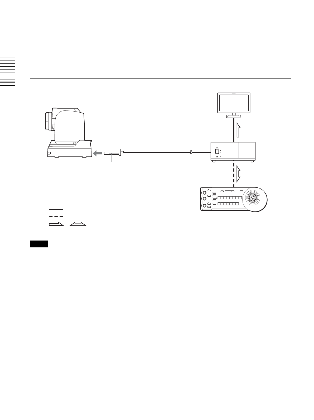
Operating a BRC-H900 Camera from a Long Distance
This system allows you:
• To operate the camera remotely from a distance up to 2,000 m (6,562 feet)
• To perform pan/tilt and zoom operations using the joystick
• To transmit the video and control signals of the camera to a distant place using the Optical Fiber Cable
System configuration
Overview
BRC-H900
CCFC-S200 Optical Fiber Cable
BRBK-SF1 HD Optical Multiplex Card
Video signal
Remote control (VISCA) signal
Signal flow
,
HD video monitor
BRU-SF10
Optical Multiplex
Unit
RM-BR300 Remote Control Unit
Notes
• Be sure to turn on the power of the BRC-H900 camera before you turn on the power of the BRU-SF10 HD Optical
Multiplex Unit.
• The BRC-H900 camera does not operate if nothing is connected to the BRBK-SF1 HD Optical Multiplex Card
inserted into the camera. To operate the camera, connect the BRU-SF10 Optical Multiplex Unit to the BRBK-SF1
using the CCFC-S200 Optical Fiber Cable and turn on the power of the BRU-SF10.
• When the BRBK-SF1 HD Optical Multiplex Card is inserted into the BRC-H900 camera, the EXT SYNC IN
connector, VISCA RS-232C IN/OUT connectors, and VISCA RS-422 connector on the rear of the camera are
disabled. Use the connectors and switches on the rear of the BRU-SF10 Optical Multiplex Unit instead.
• The optional CCFC-M100 and M100HG Optical Fiber Cable cannot be used with this system.
GB
14
System Configuration

Operating Multiple BRC-H900 Cameras from a Long Distance
This system allows you:
• To operate up to seven cameras remotely from a distance up to 2,000 m (6,562 feet)
• To perform pan/tilt and zoom operations using the joystick
• To transmit the video and control signals of the cameras to a distant place using the Optical Fiber Cable
System configuration
BRC-H900
BRC-H900
BRC-H900
CCFC-S200
Optical Fiber
Cable
BRBK-SF1 HD
Optical Multiplex Card
CCFC-S200
BRBK-SF1
CCFC-S200
BRU-SF10 Optical
Multiplex Unit
BRU-SF10
BRU-SF10
Overview
HD video monitor
Video switcher
BRBK-SF1
Video signal
Remote control (VISCA) signal
Tally/contact signal
Signal flow
,
RM-BR300 Remote Control Unit
System Configuration
15
GB

Operating Multiple BRC-H900 Cameras from Short and Long Distance
This system allows you:
• To operate up to seven cameras remotely by using a single RM-BR300 Remote Control Unit
• To perform pan/tilt and zoom operations using the joystick
• To operate remotely from a distance up to 2,000 m (6,562 feet) and to transmit the video and control signals of the
cameras to a distant place using the Optical Fiber Cable
System configuration
Overview
BRC-H900
HD video monitor
BRC-H900
BRC-H900
BRC-H900
Video signal
Remote control (VISCA) signal
Tally/contact signal
Signal flow
,
BRBK-SF1
BRBK-SF1 HD Optical
Multiplex Card
CCFC-S200
CCFC-S200
Optical Fiber
Cable
BRU-SF10
BRU-SF10 HD
Optical Multiplex
Unit
Video switcher
RM-BR300 Remote Control Unit
GB
16
System Configuration

Transmitting Audio Signals Using the BRU-SF10
This system allows you:
• To operate the camera remotely from a distance up to 2,000m (6,562 feet)
• To perform pan/tilt and zoom operations using the joystick
• To transmit the video and control signals of the camera, and the audio signal input to the BRBK-SF1 Optical Multiplex
Card, to a distant place using the Optical Fiber Cable
System configuration
Overview
BRC-H900
Video signal
Audio line signal
Remote control (VISCA) signal
,
Signal flow
Microphone
BRBK-SF1 HD
Optical Multiplex
Card
Microphone amplifier
CCFC-S200
Optical Fiber
Cable
Speakers
HD video monitor
Audio
amplifier
BRU-SF10 HD
Optical Multiplex
Unit
RM-BR300 Remote Control Unit
System Configuration
17
GB

Location and Function
67
5
qfqgqhqkqlw;w
q
of Parts
lamp does not light when TALLY MODE in the
SYSTEM menu (page 39) is set to OFF.
Flashes at intervals of about 0.7 seconds if the
rotating speed of the cooling fan motor reduces or
if the motor stops, regardless of the on/off status of
the back tally lamp.
Camera
Front
Overview
1
3
42
E SONY and HD nameplates
Pull them out to turn them over and attach upside
down if required.
F POWER lamp
Lights when the camera is connected to an AC
outlet using the supplied AC power adaptor and AC
power cord.
Flashes in green when the camera receives an
operation command from the supplied Remote
Commander.
G STANDBY lamp
Lights when the camera is turned off using the
Remote Commander.
Rear
890qa
qs qd
A Lens
This is a 14-magnification optical zoom lens.
Note
1 2 3
VISCA RS-422
IR SELECT
OFF ON HD SD
75
EXT SYNC IN
R
VIDEO S VIDEO
1 2 3 4 5 6 7 8 9
IN VISCA RS-232 OUT SDI OUT
RGB/COMPONENT
DC IN 12V
Do not touch the part around the lens and ring
outside the lens when energized. It may cause a
malfunction of the camera.
B Tally lamp
Lights in red when a VISCA tally command is
received or the camera is selected by the RMBR300 Remote Control Unit (not supplied)
(depending on the setting mode).
You can set the brightness of the tally lamp to
HIGH, LOW, or OFF on the menu.
C Remote sensor
This is the sensor for the supplied Remote
Commander.
When you use the upper remote sensor, set IMG
FLIP to ON in the SYSTEM menu (page 39). With
this setting the remote sensor at the rear of the
camera does not function.
D Back tally lamp
Lights in red when a VISCA tally command is
received or the camera is selected by the RMBR300 Remote Control Unit (not supplied)
(depending on the setting mode). The back tally
j
a
H VISCA RS-422 connector
Used for VISCA control.
For connection to the VISCA RS-422 connector,
see “Using the VISCA RS-422 Connector Plug” on
page 89.
I 75-ohm termination switch
This switch is used when an external sync signal is
used. Set it to OFF when this camera is in the
middle of a daisy-chain connection of multiple
cameras. Set it to ON when the camera is at the end
of a daisy-chain connection or when nothing is
connected to the EXT SYNC IN connector on the
camera.
J IR SELECT switch
Select the camera number when you operate
multiple cameras with the same Remote
Commander.
GB
18
Location and Function of Parts

K Remote sensor
This is the sensor for the supplied Remote
Commander.
This remote sensor does not function when IMG
FLIP is set to ON in the SYSTEM menu.
U DC IN 12V connector
Connect the supplied AC power adaptor.
Bottom
L HD/SD select switch
Outputs an SD-SDI signal from the SDI connector
when the switch is set to SD, or an HD-SDI signal
from the SDI connector when the switch is set to
HD.
Note
Set the switch before turning the camera on.
M RGB/COMPONENT connector
Supplies the images as an analog component
(YPbPr or RGB) signal.
N VISCA RS-232C IN connector
Connect to the RM-BR300 Remote Control Unit
(not supplied). When you connect multiple
cameras, connect it to the VISCA RS-232C OUT
connector of the previous camera in a daisy-chain
connection.
O VISCA RS-232C OUT connector
When you connect multiple cameras, connect it to
the VISCA RS-232C IN connector of the next
camera in a daisy-chain connection.
P EXT SYNC IN connector
Accepts external video sync signals.
Q T VIDEO connector
Outputs the camera images as a composite video
signal.
R S VIDEO connector
Outputs the camera images as an S video signal.
S SDI connector
Outputs the video signal from the camera as an HD/
SD-SDI signal.
wdws wf
Overview
V Ceiling bracket mounting screw holes
When you install the camera to the ceiling or on a
shelf, etc., in a high position, secure the supplied
ceiling bracket to these holes using the supplied
four screws. The four feet are attached to the holes
at the factory.
For installation, see “Installing the Camera in a
High Position” on page 56.
W Tripod screw holes (1/4-20UNC)
When you install the camera to a tripod, secure the
tripod to these holes.
X BOTTOM switches
Used for the output signal format selection, RS232C/RS-422 selection, baud rate selection, remote
control signal output on/off and camera address
setting.
For details, see “Setting of the BOTTOM switches”
on page 19.
Supplies down-converted SD-SDI signals that
conform to the SMPTE 259M serial digital
interface standards, or HD-SDI signals that
conform to the SMPTE 292 serial digital interface
standards. Select HD-SDI or SD-SDI signals with
the HD/SD select switch.
T Card slot
Insert the optional card, such as BRBK-HSD2,
BRBK-SA1, BRBK-SF1, etc.
The slot cover is attached to the camera at the
factory.
Setting of the BOTTOM switches
O
1
N
2
3
4
O
1
N
2
3
4
1
2
3
4
5
Location and Function of Parts
19
GB

1 Switch 1, 2 (signal format selector)
Depending on the setting of the Switch 1, 2, the
signal format is changed as follows:
Remote Commander (supplied)
Signal
format
Switch 1 OFF ON OFF ON
Switch 2 OFF OFF ON ON
2 Switch 3 (RS-232C/RS-422 selector)
Overview
3 Switch 4 (Communication baud rate selector)
4 Switch 1, 2, 3 (Camera address selectors)
1080/
59.94i
1080/50i 720/
59.94p
720/50p
Set to ON for RS-422, or OFF for RS-232C.
Set to ON for 38,400 bps, or OFF for 9,600 bps.
Set the address of the camera.
Normally set to “0”. With this setting, addresses are
assigned to the cameras automatically in the
connected order by pressing the POWER button
while holding down the RESET button on the RM-
1
2
3
4
5
1
AUTO
FAR
DATA SCREEN
STD REV
123
456
PRESET
SLOW FAST
T
W
L/R
DIRECTION SET
CAMERA SELECT
23
FOCUS
NEAR
RESET
POSITION
PAN-TILT
HOME
ZOOM
T
W
RM-EV100
POWER
MANUAL
BACK LIGHT
PAN-TILT
RESET
6
7
8
9
q;
BR300 Remote Control Unit.
You can assign the camera address “1” to “7”
manually by setting these selectors as follows:
Camera
address
Switch 1 OFF ON OFF ON OFF ON OFF ON
Switch 2 OFF OFF ON ON OFF OFF ON ON
Switch 3 OFF OFF OFF OFF ON ON ON ON
01234567
A CAMERA SELECT buttons
Press the button corresponding to the camera you
want to operate with the Remote Commander.
The camera number can be set using the IR
SELECT switch on the rear of the camera.
5 Switch 4 (Infrared signal output switch)
Set to ON to enable an infrared signal output, or
OFF to disable the output. For details about the
output connector, see “Pin Assignments” on page
85.
Note
If two or more cameras are adjacent and have the
same camera number, they are operated
simultaneously with the same Remote Commander.
When you install the cameras close to each other,
Note
Set the switches before you turn on the power of the
camera. The switch 4 (Infrared signal output switch)
setting is effective whenever you change its setting.
set different camera numbers.
For the camera number setting, see “Operating
Multiple Cameras with the Remote Commander”
on page 45.
GB
20
Location and Function of Parts
B FOCUS buttons
Used for focus adjustment.
Press the AUTO button to adjust the focus
automatically. To adjust the focus manually, press
the MANUAL button, and adjust it with the FAR
and NEAR buttons.

C DATA SCREEN button
Press this button to display PAGE of the main
menu. Press it again to turn off the menu. If you
press the button when a lower-level menu is
selected, the display goes back to a higher-level
menu.
Note
I PAN-TILT RESET button
Press this button to reset the pan/tilt position.
J ZOOM buttons
Use the SLOW button to zoom slowly, and the
FAST button to zoom quickly.
Press the T (telephoto) side of the button to zoom
in, and the W (wide angle) side to zoom out.
Pan/tilt and zoom operations are disabled when the
menu is displayed.
D PAN-TILT buttons
Press the arrow buttons to perform panning and
tilting. Press the HOME button to face the camera
back to the front.
When the menu is displayed, use V or v to select
the menu items and B or b to change the set values.
E L/R DIRECTION SET button
Hold down this button and press the REV button to
change the direction of the camera movement
opposite to that indicated by the arrow of the B/b
buttons.
To reset the direction of the camera movement,
press the STD button while holding down this
button.
F POWER button
Press this button to turn on/off the camera when the
camera is connected to an AC outlet.
G BACK LIGHT button
Press this button to enable the backlight
compensation. Press it again to disable the
backlight compensation.
Note
This function is effect when MODE in the
EXPOSURE menu is set to FULL AUTO or BACK
LIGHT.
H POSITION buttons
Hold down the PRESET button and press button 1
to 6 to store the current camera direction, zoom,
focus adjustment and backlight compensation in
the memory of the pressed number button.
To erase the memory contents, hold down the
RESET button and press button 1 to 6.
To install batteries
Overview
Two R6 (size AA)
batteries (not supplied)
Installing batteries
Two R6 (size AA) batteries are necessary for Remote
Commander (RM-EV100).
To avoid risk of explosion, use R6 (size AA) manganese
or alkaline batteries.
CAUTION
Danger of explosion if battery is incorrectly replaced.
Replace only with the same or equivalent type
recommended by the manufacturer.
When you dispose of the battery, you must obey the law
in the relative area or country.
ATTENTION
Il y a danger d’explosion s’il y a remplacement incorrect
de la batterie. Remplacer uniquement avec une batterie
du même type ou d’un type équivalent recommandé par
le constructeur.
Lorsque vous mettez la batterie au rebut, vous devez
respecter la législation en vigueur dans le pays ou la
région où vous vous trouvez.
Note
Some memory contents may not be erased even if
you use the RESET button.
For details of items that can be stored by the
PRESET button and erased by the RESET button,
see “Presetting Items” on page 78.
VORSICHT
Explosionsgefahr bei Verwendung falscher Batterien.
Batterien nur durch den vom Hersteller empfohlenen
oder einen gleichwertigen Typ ersetzen.
Wenn Sie die Batterie entsorgen, müssen Sie die Gesetze
der jeweiligen Region und des jeweiligen Landes
befolgen.
Location and Function of Parts
21
GB

RM-BR300 Remote Control Unit
qhqjqkq
w
(not supplied)
the EXPOSURE menu of the camera. For details,
see “Functions of the VALUE and BRIGHT
controls” on page 53.
This manual explains the operations of the RM-BR300
Remote Control Unit when it is used with BRC-H900
cameras.
When the white balance adjustment mode is
selected with the MODE button (with the B
indicator lit):
The function of the control with the B indicator lit
Front
varies according to the white balance mode selected
on the camera. For details, see “Functions of the R
Overview
1
VALUE
2
– +
R
BRIGHT
3
– +
B
FOCUS
4
NEAR FAR
5
90qaqsqd qf qg
8
LOCK
MODE
AUTO
AUTO
MANUAL
ONE PUSH
AF
PRESET
DIRECTION
POWER
RESET
1
SHIFT
9
STD REV
L/R
1
PANEL
BLACK
PAN-TILT
ONE PUSH
LIGHT
LIGHT
RESET
AWB
POSITION
2
3114
5136147158
12
10
CAMERA
234567
MENU
16
6
7
l
;
A LOCK button and indicator
Press the LOCK button for more than one second,
the LOCK indicator lights and the values set by the
VALUE/R, BRIGHT/B and FOCUS controls are
locked. (The indicators of the locked controls are
turned off.) The AUTO/MANUAL button is also
disabled.
Press the LOCK button for more than one second
again to unlock the controls and buttons.
B VALUE/R control
When the brightness adjustment mode is
selected with the MODE button (with the
VALUE indicator lit):
Adjusts the value of the item (SHUTTER, IRIS or
GAIN) selected through the menu of the camera.
When the VALUE indicator is lit, the function of
the control varies according to the MODE setting in
the EXPOSURE menu of the camera. For details,
see “Functions of the VALUE and BRIGHT
controls” on page 53.
When the white balance adjustment mode is
selected with the MODE button (with the R
indicator lit):
The function of the control with the R indicator lit
varies according to the white balance mode selected
and B controls” on page 52.
D MODE button
Press this button to select the function of the
VALUE/R control and BRIGHT/B control.
When the brightness adjustment mode is selected,
the VALUE and BRIGHT indicators are lit.
When the white balance adjustment mode is
selected, the R and B indicators are lit.
E FOCUS control
Turn this control counterclockwise (toward NEAR)
to focus on a near subject, and clockwise (toward
FAR) to focus on a far subject.
F AUTO/MANUAL button and AUTO indicator
Press this button to select focus mode, AUTO or
MANUAL.
When AUTO is selected, the AUTO indicator lights
and the FOCUS control and the ONE PUSH AF
button are disabled.
When MANUAL is selected, the FOCUS control
and the ONE PUSH AF button are enabled (with
the FOCUS indicator lit).
G ONE PUSH AF button
Press this button to perform the one-push auto focus
function.
H RESET button
Hold down this button and press one of the
POSITION buttons, and the memory of the camera
corresponding to the pressed POSITION button is
cleared to the factory-preset conditions.
When multiple cameras are connected, hold down
this button and press the POWER button to set the
camera addresses automatically.
on the camera. For details, see “Functions of the R
and B controls” on page 52.
Note
Some memory contents may not be erased even if
C BRIGHT/B control
When the brightness adjustment mode is
selected with the MODE button (with the
you use the RESET button.
For details about item erased by the RESET button,
see “Presetting Items” on page 78.
BRIGHT indicator lit):
Adjusts the brightness settings of the camera, etc.
When the BRIGHT indicator is lit, the function of
the control varies according to the MODE setting in
GB
22
Location and Function of Parts

I PRESET button
Hold down this button and press one of the
POSITION buttons, and the current camera settings
are stored in the memory of the camera
corresponding to the pressed POSITION button.
J PANEL LIGHT button
Press this button to illuminate all the POSITION
buttons and CAMERA buttons. Press the button
again to turn off the illumination.
K BACK LIGHT button
When FULL AUTO, or BACK LIGHT is selected
with MODE of the EXPOSURE menu, press this
button to set the backlight compensation function
of the camera to on/off. Each time you press this
button, the backlight compensation function
toggles between on and off.
When FULL AUTO or SPOT LIGHT is selected
with MODE of the EXPOSURE menu, hold down
the SHIFT button and press this button to set the
spotlight compensation function of the camera to
on/off. Each time you press this button, the
spotlight compensation function toggles between
on and off.
L PAN-TILT RESET button
Press this button to reset the pan/tilt position of the
camera to the initial conditions.
M ONE PUSH AWB button
When ONE PUSH is selected with the WHITE
BALANCE menu of the camera, press this button
to perform the one-push white balance adjustment.
N MENU button
Press this button for about one second to display or
turn off the menu of the camera, or return to the
main menu.
O Joystick
When the menu of the camera is not
displayed
The joystick is used for pan/tilt and zoom
operations.
When you incline the joystick right and left, the
camera pans. When you incline it forward or
backward, the camera tilts. The pan/tilt speed
changes according to the angle of the inclination.
When you release the joystick, the camera
movement stops.
When you turn the dial on the upper part of the
joystick clockwise, the subject becomes larger
(zoom in). When you turn it counterclockwise, the
subject becomes smaller (zoom out).
When you press the button on the top of the joystick
for one or two seconds regardless of the PAN TILT
ZOOM menu setting, the pan/tilt/zoom are reset
and the camera returns to the front.
When the menu of the camera is displayed
The joystick is used for menu operations.
Inclining the joystick right, left, forward and
backward has the same function as pressing the
arrow buttons of the supplied Remote Commander.
Pressing the button on the top of the joystick has the
same function as pressing the HOME button on the
Remote Commander.
P SHIFT button and indicators
Hold down this button and press one of the
POSITION buttons. The lower indicator lights and
you can use the POSITION buttons for positions 9
to 16. If you release the SHIFT button, the upper
indicator lights and the POSITION buttons can be
used for positions 1 to 8.
Q L/R DIRECTION button
Hold down this button and press POSITION button
2 (REV) to reverse the pan direction to the direction
in which you incline the joystick. To reset the
direction, hold down this button and press
POSITION button 1 (STD).
R POWER button
Press this button to light the CAMERA button(s)
corresponding to the status of the connected
camera(s).
Blue: The power of the camera is on.
Yellow green: The camera is in standby mode.
Off: No camera is connected.
Hold down this button and press CAMERA button
1 to 7 to turn on/off the power of the camera
corresponding to the pressed button.
S CAMERA buttons
Press one of the buttons to select the camera from
among those connected. The selected CAMERA
button lights in blue.
T POSITION buttons
You can store the various camera settings such as
the pan, tilt and zoom positions to the memory of
the camera corresponding to each POSITION
button, and load the settings in the memory.
Overview
Location and Function of Parts
23
GB

Rear/Bottom
wswdwfwgwhwjw
w
Y TALLY/CONTACT selector
Select the function of the TALLY/CONTACT
connector.
TAL LY: The tally lamp of the camera selected with
the connected switcher lights.
CONTACT: The contact output corresponding to
the camera address selected with the Remote
MODE
RS-232C
TALLY/CONTACT
CONTACT(TALLY)
TALLY
CONTACT DC IN 12V
RS-422 ON/OFF
VISCA
1919
!
Control Unit is short-circuited against the
connected switcher.
CONTACT (TALLY): The contact output
Overview
a
k
corresponding to the camera address selected with
the Remote Control Unit is short-circuited against
the connected switcher and the tally lamp of the
U MODE selector
camera selected with the connected switcher lights.
Select the position corresponding to the VISCAcontrollable camera to be connected.
Notes
• Change the setting of the selector before you turn
Switch position Camera mode
0 Automatically selected (default)
1 BRC-300/300P
2 EVI-D70/D70P
3 EVI-D100/D100P
4 EVI-D30/D30P
5SNC-RZ30N
6 BRC-H700
7 BRC-Z700
8 BRC-Z330
9 BRC-H900
on the power of the Remote Control Unit.
Otherwise, the setting is not effective.
• For details about the TALLY/CONTACT
selector, refer to the Operating Instructions of
RM-BR300.
wh DC IN 12V connector
Connect the supplied AC power adaptor.
wj DIP switches (bottom)
Switch 1 (RS-232C/RS-422 selector)
Set to ON for RS-422, or OFF for RS-232C.
Switch 2 (Communication baud rate selector)
Note
Set to ON for 38,400 bps, or OFF for 9,600 bps.
Set the selector to position 9 when all the connected
cameras are BRC-H900s. For other connections, set
the selector to position 0.
V VISCA RS-232C connector
Connect to the VISCA RS-232C IN connector of
the camera or the BRU-SF10 HD Optical Multiplex
Unit.
W VISCA RS-422 connector
Connect to the VISCA RS-422 connector of the
camera or the BRU-SF10 HD Optical Multiplex
Unit.
An RS-422 connector plug is attached at the
factory.
X TALLY/CONTACT connector
This connector is used for the tally lamp input or the
contact output.
Select the function of the connector using the
TALLY/CONTACT selector.
An RS-422 connector plug is attached at the
factory.
Switch 3 (BRIGHT control function selector)
Set to ON for IRIS and GAIN adjustments, or OFF
for IRIS adjustment only.
Note
Set the DIP switches before you turn on the power
of the Remote Control Unit. Otherwise, the setting
is not effective.
wk ON/OFF switch
Press this switch to turn on/off the Remote Control
Unit.
GB
24
Location and Function of Parts

BRU-SF10 HD Optical Multiplex
q
q
q
Unit (not supplied)
Front
• An unsupported optional interface card is
inserted in the card slot of the BRU-SF10.
Remove the card after turning off the power,
then restart the unit.
Off: The unit is in normal operation.
26
3451
ON/STANDBY
LINK
ALARM
SDDATA MIX
ONOFF
1234567
1080i
59.9450RS232C
720p
HD OPTICAL MULTIPLEX UNIT
RS422
9600bps
38400bps
8
A Power switch
Turns on/off the power of this unit. Turn on the
power of the BRC-H900 camera before you turn on
this unit.
B Power indicator
Off: The unit’s power switch is turned off.
Lit orange: The unit is starting up or in sleep mode.
Lit green: The unit is in normal operation.
C LINK indicator
Lit green: The optical fiber connection between the
unit and the camera is normal. (The indicator
lights in green after the system starts up.)
Lit red: Check for the following.
• The BRU-SF10 is not properly connected to
the camera via optical fiber cable. Check the
connections, and restart the unit.
• Image frequency settings for the camera and
the BRU-SF10 are different. Check the
settings after turning off the power, then
restart the unit.
• The camera may be unable to start properly
due to the AC adaptor being improperly
connected to the DC IN connector on the
camera. Check that the camera is turned on.
D ALARM indicator
Lit red: Check for the following.
• The BRU-SF10 is not properly connected to
the camera via an optical fiber cable. Check
the connections, then restart the unit.
• Image frequency settings for the camera and
the BRU-SF10 are different. Check the
settings after turning off the power, then
restart the unit.
• The camera may be unable to start properly
due to the AC adaptor being improperly
connected to the DC IN connector on the
camera. Check that the camera is turned on.
7
E SD indicator
This indicator lights when a BRBK-SA1 optional
interface card is installed, or when a BRBK-HSD2
is installed and its rear switch is set to SD.
F Camera ID indicators
The number for the current camera address lights in
orange.
For details on setting the camera address, see
“Q VISCA FUNCTION switches” on page 26.
G Status indicators
The current communication format, baud rate, and
video format settings light in green.
For details on configuring these settings, see
“Q VISCA FUNCTION switches” on page 26.
H DATA MIX switch
When the SD indicator is lit, set this switch to ON
to overlap the menu display with the SD image
signals from any installed BRBK-SA1 and
BRBK-HSD2 interface card on which the rear
switch is set to SD.
Set this switch to OFF to hide the menu display.
Rear
9qgqh0qa qs qdqf
IN OUT IN OUT
EXT SYNC
CAMERA
RGB/COMPONENT
l
VISCA
RS232C
123456789
VISCA RS422
L
R
DC 12V
k
AUDIO OUT
FUNCTION
1
10
I CAMERA connector
Connect to the optical connector of the BRBK-SF1
HD Optical Multiplex Card installed in the
BRC-H900 camera using the CCFC-S200 Optical
Fiber Cable.
A dustproof cap is attached at the factory.
Do not remove this cap if you do not intend to
connect an optical fiber cable. Dustproof caps are
also attached to the BRBK-SF1 and CCFC-S200.
Do not remove these caps when the connectors are
not in use.
J EXT SYNC IN connector
Accepts external video sync signals.
Overview
j
GB
Location and Function of Parts
25

K EXT SYNC OUT connector
Supplies external video sync signals input from the
EXT SYNC IN connector.
When a cable is connected to this connector, the
75-ohm termination for inputs is automatically
opened, and signals input to the EXT SYNC IN
connector are output from this connector.
Switches 3 to 5 (Camera address selectors)
Set the address of the camera.
Normally set to “0”. With this setting, addresses are
assigned to the cameras automatically in the
connected order by pressing the POWER button
while holding down the RESET button on the
RM-BR300 Remote Control Unit (not supplied).
You can assign the camera address “1” to “7’
L RGB/COMPONENT connector
manually by setting these selectors as follows:
Supplies the images from the camera as a YPbPr or
Overview
RGB signal.
M VISCA RS-232C IN connector
Connect to the RM-BR300 Remote Control Unit
(not supplied). When you connect multiple
cameras, connect it to the VISCA RS-232C OUT
Camera
address
Switch 3 OFF ON OFF ON OFF ON OFF ON
Switch 4 OFF OFF ON ON OFF OFF ON ON
Switch 5 OFF OFF OFF OFF ON ON ON ON
01234567
connector of the previous camera in a daisy-chain
connection.
N VISCA RS-232C OUT connector
When you connect multiple cameras, connect it to
the VISCA RS-232C IN connector of the next
camera in a daisy-chain connection.
Note
Cameras with addresses assigned by setting the
switches to “0” and cameras with addresses
assigned to “1” to “7” cannot be used together. In
addition, the same address cannot be assigned to
multiple cameras.
Caution
When you connect the RS-232C connecting cable
of the unit to a peripheral device, use the supplied
cable to prevent malfunction due to radiation noise.
O VISCA RS-422 connector
Connect to the VISCA RS-422 connector of the
camera or another BRC-H900 HD Optical
Multiplex Unit.
For the connection to the VISCA RS-422
connector, see “Using the VISCA RS-422
Connector Plug” on page 89.
P AUDIO OUT L/R jacks
Loop through output of the audio line signal input
from the AUDIO IN jacks on the BRBK-SF1 HD
Optical Multiplex Card inserted into the camera via
the Optical Fiber Cable.
Q VISCA FUNCTION switches
These switches are used for the VISCA
communication settings.
Switch 6 (59.94/50 signal format selector)
Set to ON for output of 50 signal format, or OFF for
output of 59.94 signal format.
The 1080i and 720p formats are automatically
applied to this unit based on the BOTTOM switch
setting of the camera.
Be sure to configure the same setting on this unit
and the camera.
Switches 7 to 10: Not used. Set them to OFF.
Note
Set the switches before you turn on the power of the
unit.
R DC 12 V connector
Connect to the supplied AC adaptor.
S Card slot
Install BRBK-SA1 or BRBK-HSD2 optional
interface card here.
The slot cover is attached to the unit at the factory.
GB
Switch 1 (RS-232C/RS-422 selector)
Set to ON for RS-422, or OFF for RS-232C.
Switch 2 (Communication baud rate
selector)
Set to ON for 38,400 bps, or OFF for 9,600 bps.
26
Location and Function of Parts

BRBK-SF1 HD Optical Multiplex
Card (not supplied)
21
BRBK-SF1
LR
AUDIO IN BRU
B SDI connectors 1, 2 (BNC type)
Outputs down-converted SD-SDI signals that
conform to SMPTE 259M serial digital interface
standards, and down-converted HD-SDI signals
that conform to SMPTE 292 serial digital interface
standards.
When the menu display for the camera is turned
ON, you can select whether to overlap the menu
display with the image by using the C panel
switch. For details, see “Images when menu display
is ON” on page 27.
Overview
A AUDIO IN L/R jacks (phono type)
Input an audio signal (stereo), which is output from
the AUDIO OUT jacks on the BRU-SF10 HD
Optical Multiplex Unit via the Optical Fiber Cable.
Note
The audio input on this card accepts audio line
signals only. When you input audio signals from a
microphone, etc., it should be connected with a
microphone amplifier so that audio signals with an
appropriate audio level can be input.
B Optical connector
Performs the optical digital multiplex transmission
of video, audio, external sync and control signals.
A dustproof cap is attached at the factory.
BRBK-HSD2 HD/SD-SDI Output
Card (not supplied)
132
MONITOR
BRBK-HSD2
A SDI MONITOR OUT connector (BNC type)
Outputs down-converted SD-SDI signals that
conform to SMPTE 259M serial digital interface
standards, and down-converted HD-SDI signals
that conform to SMPTE 292 serial digital interface
standards.
When the menu display for the camera is turned
ON, the menu display signal that overlaps the
images is output from this connector. When the SDSDI output card is installed in the card slot of the
BRU-SF10 HD Optical Multiplex Unit, you can
also hide the menu display by using the DATA MIX
switch on the BRU-SF10. For details, see “Images
when menu display is ON” on page 27.
12
SDI OUT
OFF
ON
HD SD
C Panel switch
Switch between SD-SDI signals and HD-SDI
signals.
When outputting HD-SDI signals, you can select
whether to overlap the menu display with the image
output from SDI connectors 1 and 2. For details, see
“Images when menu display is ON” on page 27.
Notes
• SD-SDI and HD-SDI signals cannot be supplied
simultaneously.
• Set the panel switch before turning on the
camera.
• Do not push the switch forcibly with a
screwdriver, etc.
Images when menu display is ON
When a BRBK-HSD2 is installed in the
BRC-H900 card slot
BRBK-HSD2
panel switch
Left position HD/
DATA MIX: ON
(HD-SDI output)
Middle position HD/
DATA MIX: OFF
(HD-SDI output)
Right position SD
(SD-SDI output)
MONITOR
connector
a ×
a: Menu is superimposed on image
×: Menu is not superimposed on image
SDI connectors
1, 2
a
a
Location and Function of Parts
27
GB

When a BRBK-HSD2 is installed in the
BRU-SF10 card slot
DATA MIX switch is set to OFF, the menu will not be
displayed on the image, even if menu display for the
camera is turned ON.
BRBK-HSD2
panel switch
Left position HD/
DATA MIX: ON
(HD-SDI output)
Middle position HD/
DATA MIX: OFF
Overview
(HD-SDI output)
Right position SD
(SD-SDI output)
1)
When the DATA MIX switch on the front panel of the
MONITOR
connector
a ×
a: Menu is superimposed on image
×: Menu is not superimposed on image
SDI connectors
1, 2
a
1)
a/×
BRU-SF10 HD Optical Multiplex Unit is set to ON,
the menu display is overlapped on all images output
from the card. When the DATA MIX switch is set to
OFF, the menu is not displayed.
BRBK-SA1 Analog SD Output Card
(not supplied)
12 3
BRBK-SA1
VIDEO S-VIDEO
RGB/SYNC
A T VIDEO connector (BNC type)
Supplies analog composite signals. The aspect ratio
can be configured in the SD menu of the camera.
B S VIDEO connector (4-pin mini-DIN)
Outputs S-Video signals. You can configure the
aspect ratio with the SD menu of the camera.
C RGB/SYNC connector (D-sub 9-pin)
Supplies various analog signals such as composite
video, S video, component video and RGB signals.
The output signal can be selected in the SD menu of
the camera.
Notes
• When a BRBK-SA1 Analog SD Output Card is
installed in the BRC-H900 HD Color Video Camera
and menu display for the camera is turned ON, the
menu display is overlapped with the image.
• When a BRBK-SA1 Analog SD Output Card is
installed in a BRU-SF10 HD Optical Multiplex Unit
on which the front panel DATA MIX switch is set to
ON and menu display for the camera is turned ON, the
menu display is overlapped with the image. When the
GB
28
Location and Function of Parts

Adjusting and Setting With Menus
Setting Menus
The setting menu selected on the main menu is
displayed.
About On-Screen Menus
You can change various settings, such as shooting
conditions and system setup of the camera, while
observing menus displayed on a connected monitor.
This section explains how to read the on-screen menus
before starting menu operations.
For full details of menu configurations, see page 75.
Note
You cannot perform pan/tilt and zoom operations while
the menu is displayed.
Main Menu
To display the main menu, press the DATA SCREEN
button on the supplied Remote Commander or the
MENU button on the RM-BR300 Remote Control Unit.
<MENU> OPT
>EXPOSURE
COLOR
DETAIL
COLOR DETAIL
KNEE
GAMMA
FLICKER CANCEL
FOCUS
PAN TILT
SYSTEM
VIDEO OUT
SD
SD-SDI
1 Cursor
Selects a setting menu.
Move the cursor up or down by pressing the V or v
button on the Remote Commander or by inclining
the joystick of the RM-BR300 Remote Control
Unit forward or backward.
<SYSTEM>
>IR RECEIVE ON
IMG FLIP OFF
PAN REVERSE OFF
TILT REVERSE OFF
DISPLAY INFO ON
SYNC MASTER HD
HPHASE 03
HPHASE FINE 0
STEADY SHOT OFF
COLOR BAR OFF
TALLY MODE LOW
VERSION 1.00
1 Setting menu
The name of the menu currently selected is
displayed here.
2 Cursor
Selects a setting item.
Move the cursor up or down by pressing the V or v
button on the Remote Commander or inclining the
joystick of the RM-BR300 Remote Control Unit
forward or backward.
3 Setting items
The setting items for this setting menu are
displayed.
To change a value, select the item using the V or v
button on the Remote Commander or the joystick of
the RM-BR300 Remote Control Unit, and press the
B or b button on the Remote Commander or incline
the joystick on the RM-BR300 right or left.
4 Set value
The currently set values are displayed.
To change a set value, use the B or b button on the
Remote Commander or the joystick of the RMBR300 Remote Control Unit.
For the default value of each setting item, see
“Menu Configuration” on page 75.
Adjusting and Setting With Menus
2 Menu items
To display a setting menu, select it using the V or v
button on the Remote Commander or the joystick of
the RM-BR300 Remote Control Unit, and press the
HOME button on the Remote Commander or the
top button of the joystick on the RM-BR300.
3 Option card indicator
Displays the name of the interface card inserted into
the card slot of the camera.
About On-Screen Menus
29
GB

Operation Through
3
Press the HOME button.
The selected menu appears.
Menus
This section explains how to operate the menu using the
supplied Remote Commander, or using the RM-BR300
Remote Control Unit (not supplied).
For details on each menu, see pages 32 through 42.
<SYSTEM>
>IR RECEIVE ON
IMG FLIP OFF
PAN REVERSE OFF
TILT REVERSE OFF
DISPLAY INFO ON
SYNC MASTER HD
HPHASE 03
HPHASE FINE 0
STEADY SHOT OFF
COLOR BAR OFF
TALLY MODE LOW
VERSION 1.00
Menu Operation Using the Supplied
4
Remote Commander
Adjusting and Setting With Menus
POWER
3
MANUAL
CAMERA SELECT
12
NEAR
FOCUS
BACK LIGHT
FAR
AUTO
DATA SCREEN
1
2, 4
STD
3
REV
21
456
POSITION
PRESET
5
RESET
PAN-TILT
3
PAN-TILT
RESET
HOME
FAST
T
ZOOM
SLOW
W
T
RM-EV100
W
L/R
DIRECTION SET
Move the cursor to the setting item to be changed
by pressing the V or v button.
5
Change the value by pressing the B or b button.
<SYSTEM>
>IR RECEIVE ON
IMG FLIP OFF
PAN REVERSE OFF
TILT REVERSE OFF
DISPLAY INFO ON
SYNC MASTER HD
HPHASE 03
HPHASE FINE 0
STEADY SHOT OFF
COLOR BAR OFF
TALLY MODE LOW
VERSION 1.00
1
Press the DATA SCREEN button.
The main menu appears.
<MENU> OPT
>EXPOSURE
COLOR
DETAIL
COLOR DETAIL
KNEE
GAMMA
FLICKER CANCEL
FOCUS
PAN TILT
SYSTEM
VIDEO OUT
SD
SD-SDI
2
Move the cursor to the menu item to be set by
pressing the V or v button.
Note
When you are operating the menu using the supplied
Remote Commander, you cannot set IR RECEIVE in the
SYSTEM menu to OFF. To set IR RECEIVE to OFF,
use the RM-BR300 Remote Control Unit or the VISCA
command.
To return to the main menu
Press the DATA SCREEN button.
To return to the normal display
When the main menu is displayed, press the DATA
SCREEN button. When a sub-menu is displayed, press
it twice.
GB
30
Operation Through Menus
 Loading...